
Numerical simulation on a novel shell-and-tube heat ...
12
Research Article Advances in Mechanical Engineering 2017, Vol. 9(8) 1–12 Ó The Author(s) 2017 DOI: 10.1177/1687814017717665 journals.sagepub.com/home/ade Numerical simulation on a novel shell-and-tube heat exchanger with screw cinquefoil orifice baffles Xuankai Zhang, Dong Han, Weifeng He, Chen Yue and Wenhao Pu Abstract A novel shell-and-tube heat exchanger with screw cinquefoil orifice baffles is designed to grasp the weakness of the traditional shell-and-tube heat exchanger with cinquefoil orifice baffles. It specifically enhances the heat transfer coeffi- cient in the area between adjacent baffles and enhances the shell-side fluid flushing ability on bundles. In the proposed shell-and-tube heat exchanger with screw cinquefoil orifice baffles, screw-type cinquefoil orifice baffles are installed in the shell side. Shell-and-tube heat exchanger with screw cinquefoil orifice baffle is compared with shell-and-tube heat exchanger with cinquefoil orifice baffles and the traditional shell-and-tube heat exchanger with segmental baffles by means of numerical simulations. The numerical result shows that the heat transfer coefficient and shell-side fluid flushing ability in the shell-and-tube heat exchanger with screw cinquefoil orifice baffle is higher than that in the shell-and-tube heat exchanger with cinquefoil orifice baffles and shell-and-tube heat exchanger with segmental baffles, for the shell-side fluid that is urged to flow in approximately continuous helical flow. Under the same shell-side mass flow rate, heat trans- fer coefficient of shell-and-tube heat exchanger with screw cinquefoil orifice baffle is about 9.2% higher than that of shell-and-tube heat exchanger with cinquefoil orifice baffles and shell-and-tube heat exchanger with segmental baffles by about 5.4% on average. The article presents a novel design thought when researchers design heat exchangers. Keywords Computational fluid dynamics, heat exchanger, heat and mass transfer, numerical analysis, cinquefoil orifice baffle Date received: 6 November 2016; accepted: 2 June 2017 Academic Editor: Oronzio Manca Introduction Shell-and-tube heat exchangers (STHXs) have been widely used in the chemical engineering, aviation indus- try, and so on for their wide range of allowable design pressures and temperatures. 1 However, shell-and-tube heat exchanger with segmental baffles (STHX-SG), the most widely used, has many disadvantages. For exam- ple, the shell-side fluid in STHX-SG flows across tube bundles in a zigzag manner, which could lead to a great flow resistance and a high vibration level. Other issues like the ‘‘dead’’ flow region and fouling, which cause low heat transfer efficiency, 2–4 also trouble such heat exchanger users. To change this situation, many novel STHXs have been proposed. The STHX with orifice baffles was originally pro- posed by Phillips Petroleum Company, 5 which has been widely used as heat exchanger for steam generator of nuclear power plants. 6,7 In the STHX with orifice baf- fles, orifice plates have been developed as a support to tubes, and the shell-side fluid flows longitudinally through the gaps between the orifice edges and tube College of Energy and Power Engineering, Nanjing University of Aeronautics and Astronautics, Nanjing, China Corresponding author: Dong Han, College of Energy and Power Engineering, Nanjing University of Aeronautics and Astronautics, Nanjing 210016, China. Email: [email protected] Creative Commons CC-BY: This article is distributed under the terms of the Creative Commons Attribution 4.0 License (http://www.creativecommons.org/licenses/by/4.0/) which permits any use, reproduction and distribution of the work without further permission provided the original work is attributed as specified on the SAGE and Open Access pages (https://us.sagepub.com/en-us/nam/ open-access-at-sage).
-
Upload
khangminh22 -
Category
Documents
-
view
1 -
download
0
Transcript of Numerical simulation on a novel shell-and-tube heat ...
Research Article
Advances in Mechanical Engineering2017, Vol. 9(8) 1–12� The Author(s) 2017DOI: 10.1177/1687814017717665journals.sagepub.com/home/ade
Numerical simulation on a novelshell-and-tube heat exchanger withscrew cinquefoil orifice baffles
Xuankai Zhang, Dong Han, Weifeng He, Chen Yue and Wenhao Pu
AbstractA novel shell-and-tube heat exchanger with screw cinquefoil orifice baffles is designed to grasp the weakness of thetraditional shell-and-tube heat exchanger with cinquefoil orifice baffles. It specifically enhances the heat transfer coeffi-cient in the area between adjacent baffles and enhances the shell-side fluid flushing ability on bundles. In the proposedshell-and-tube heat exchanger with screw cinquefoil orifice baffles, screw-type cinquefoil orifice baffles are installed inthe shell side. Shell-and-tube heat exchanger with screw cinquefoil orifice baffle is compared with shell-and-tube heatexchanger with cinquefoil orifice baffles and the traditional shell-and-tube heat exchanger with segmental baffles bymeans of numerical simulations. The numerical result shows that the heat transfer coefficient and shell-side fluid flushingability in the shell-and-tube heat exchanger with screw cinquefoil orifice baffle is higher than that in the shell-and-tubeheat exchanger with cinquefoil orifice baffles and shell-and-tube heat exchanger with segmental baffles, for the shell-sidefluid that is urged to flow in approximately continuous helical flow. Under the same shell-side mass flow rate, heat trans-fer coefficient of shell-and-tube heat exchanger with screw cinquefoil orifice baffle is about 9.2% higher than that ofshell-and-tube heat exchanger with cinquefoil orifice baffles and shell-and-tube heat exchanger with segmental baffles byabout 5.4% on average. The article presents a novel design thought when researchers design heat exchangers.
KeywordsComputational fluid dynamics, heat exchanger, heat and mass transfer, numerical analysis, cinquefoil orifice baffle
Date received: 6 November 2016; accepted: 2 June 2017
Academic Editor: Oronzio Manca
Introduction
Shell-and-tube heat exchangers (STHXs) have beenwidely used in the chemical engineering, aviation indus-try, and so on for their wide range of allowable designpressures and temperatures.1 However, shell-and-tubeheat exchanger with segmental baffles (STHX-SG), themost widely used, has many disadvantages. For exam-ple, the shell-side fluid in STHX-SG flows across tubebundles in a zigzag manner, which could lead to a greatflow resistance and a high vibration level. Other issueslike the ‘‘dead’’ flow region and fouling, which causelow heat transfer efficiency,2–4 also trouble such heatexchanger users. To change this situation, many novelSTHXs have been proposed.
The STHX with orifice baffles was originally pro-posed by Phillips Petroleum Company,5 which has beenwidely used as heat exchanger for steam generator ofnuclear power plants.6,7 In the STHX with orifice baf-fles, orifice plates have been developed as a support totubes, and the shell-side fluid flows longitudinallythrough the gaps between the orifice edges and tube
College of Energy and Power Engineering, Nanjing University of
Aeronautics and Astronautics, Nanjing, China
Corresponding author:
Dong Han, College of Energy and Power Engineering, Nanjing University
of Aeronautics and Astronautics, Nanjing 210016, China.
Email: [email protected]
Creative Commons CC-BY: This article is distributed under the terms of the Creative Commons Attribution 4.0 License
(http://www.creativecommons.org/licenses/by/4.0/) which permits any use, reproduction and distribution of the work without
further permission provided the original work is attributed as specified on the SAGE and Open Access pages (https://us.sagepub.com/en-us/nam/
open-access-at-sage).
walls. This heat exchanger not only has a lower pres-sure drop, but also being less liable to fouls, eliminatesstagnant recirculation zones and avoids flow-inducedvibration compared to the conventional STHX-SG.6,8
Because of these advantages, the STHX with orificebaffles attracted considerable attention in recent years.
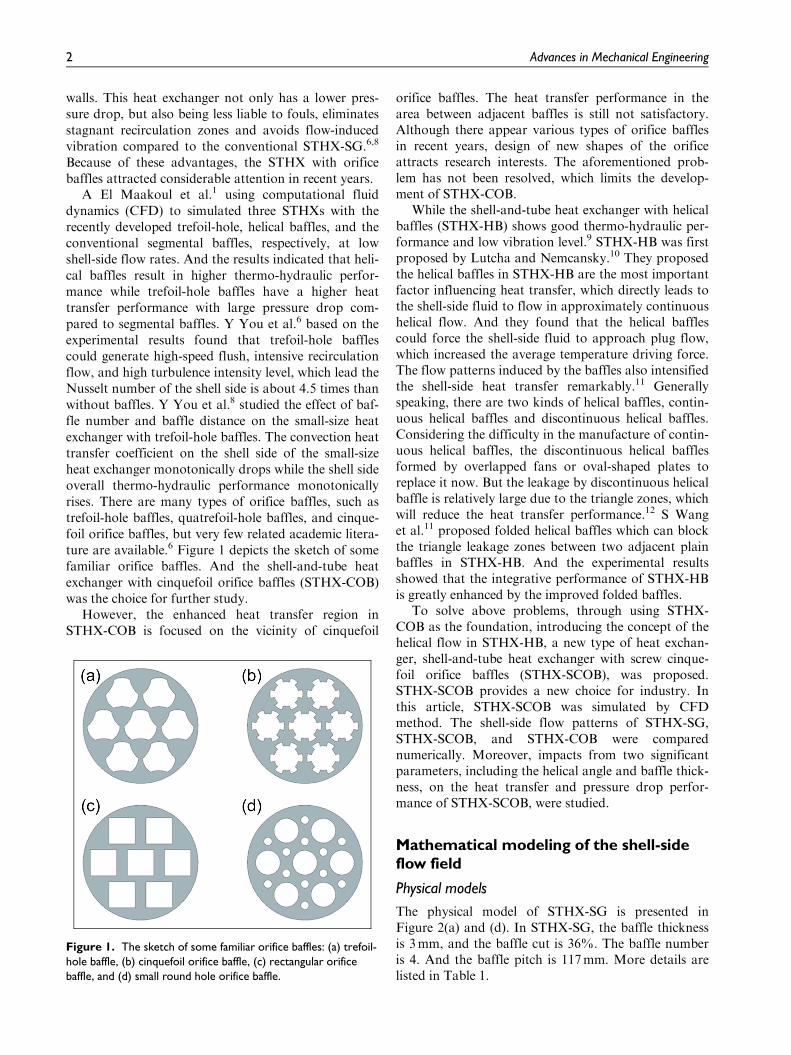
A El Maakoul et al.1 using computational fluiddynamics (CFD) to simulated three STHXs with therecently developed trefoil-hole, helical baffles, and theconventional segmental baffles, respectively, at lowshell-side flow rates. And the results indicated that heli-cal baffles result in higher thermo-hydraulic perfor-mance while trefoil-hole baffles have a higher heattransfer performance with large pressure drop com-pared to segmental baffles. Y You et al.6 based on theexperimental results found that trefoil-hole bafflescould generate high-speed flush, intensive recirculationflow, and high turbulence intensity level, which lead theNusselt number of the shell side is about 4.5 times thanwithout baffles. Y You et al.8 studied the effect of baf-fle number and baffle distance on the small-size heatexchanger with trefoil-hole baffles. The convection heattransfer coefficient on the shell side of the small-sizeheat exchanger monotonically drops while the shell sideoverall thermo-hydraulic performance monotonicallyrises. There are many types of orifice baffles, such astrefoil-hole baffles, quatrefoil-hole baffles, and cinque-foil orifice baffles, but very few related academic litera-ture are available.6 Figure 1 depicts the sketch of somefamiliar orifice baffles. And the shell-and-tube heatexchanger with cinquefoil orifice baffles (STHX-COB)was the choice for further study.
However, the enhanced heat transfer region inSTHX-COB is focused on the vicinity of cinquefoil
orifice baffles. The heat transfer performance in thearea between adjacent baffles is still not satisfactory.Although there appear various types of orifice bafflesin recent years, design of new shapes of the orificeattracts research interests. The aforementioned prob-lem has not been resolved, which limits the develop-ment of STHX-COB.
While the shell-and-tube heat exchanger with helicalbaffles (STHX-HB) shows good thermo-hydraulic per-formance and low vibration level.9 STHX-HB was firstproposed by Lutcha and Nemcansky.10 They proposedthe helical baffles in STHX-HB are the most importantfactor influencing heat transfer, which directly leads tothe shell-side fluid to flow in approximately continuoushelical flow. And they found that the helical bafflescould force the shell-side fluid to approach plug flow,which increased the average temperature driving force.The flow patterns induced by the baffles also intensifiedthe shell-side heat transfer remarkably.11 Generallyspeaking, there are two kinds of helical baffles, contin-uous helical baffles and discontinuous helical baffles.Considering the difficulty in the manufacture of contin-uous helical baffles, the discontinuous helical bafflesformed by overlapped fans or oval-shaped plates toreplace it now. But the leakage by discontinuous helicalbaffle is relatively large due to the triangle zones, whichwill reduce the heat transfer performance.12 S Wanget al.11 proposed folded helical baffles which can blockthe triangle leakage zones between two adjacent plainbaffles in STHX-HB. And the experimental resultsshowed that the integrative performance of STHX-HBis greatly enhanced by the improved folded baffles.
To solve above problems, through using STHX-COB as the foundation, introducing the concept of thehelical flow in STHX-HB, a new type of heat exchan-ger, shell-and-tube heat exchanger with screw cinque-foil orifice baffles (STHX-SCOB), was proposed.STHX-SCOB provides a new choice for industry. Inthis article, STHX-SCOB was simulated by CFDmethod. The shell-side flow patterns of STHX-SG,STHX-SCOB, and STHX-COB were comparednumerically. Moreover, impacts from two significantparameters, including the helical angle and baffle thick-ness, on the heat transfer and pressure drop perfor-mance of STHX-SCOB, were studied.
Mathematical modeling of the shell-sideflow field
Physical models
The physical model of STHX-SG is presented inFigure 2(a) and (d). In STHX-SG, the baffle thicknessis 3mm, and the baffle cut is 36%. The baffle numberis 4. And the baffle pitch is 117mm. More details arelisted in Table 1.
Figure 1. The sketch of some familiar orifice baffles: (a) trefoil-hole baffle, (b) cinquefoil orifice baffle, (c) rectangular orificebaffle, and (d) small round hole orifice baffle.
2 Advances in Mechanical Engineering
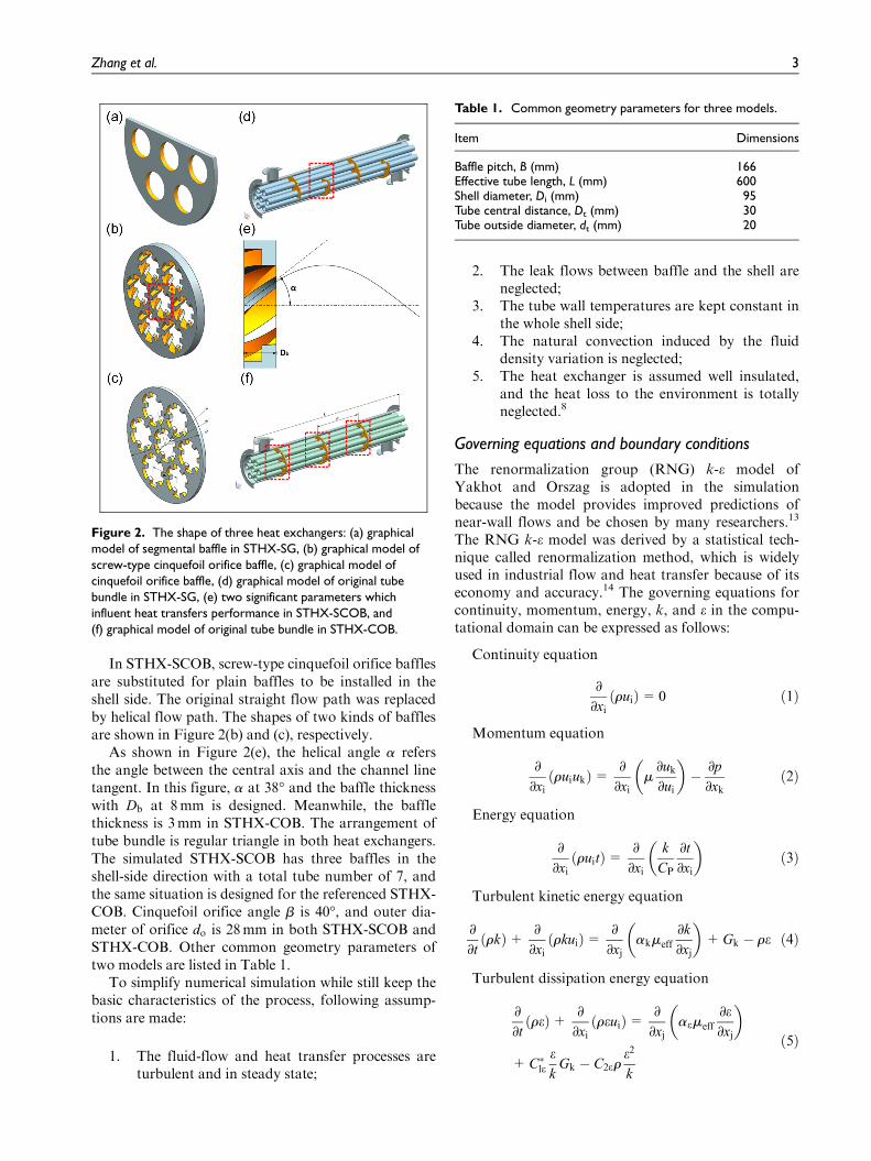
In STHX-SCOB, screw-type cinquefoil orifice bafflesare substituted for plain baffles to be installed in theshell side. The original straight flow path was replacedby helical flow path. The shapes of two kinds of bafflesare shown in Figure 2(b) and (c), respectively.
As shown in Figure 2(e), the helical angle a refersthe angle between the central axis and the channel linetangent. In this figure, a at 38� and the baffle thicknesswith Db at 8mm is designed. Meanwhile, the bafflethickness is 3mm in STHX-COB. The arrangement oftube bundle is regular triangle in both heat exchangers.The simulated STHX-SCOB has three baffles in theshell-side direction with a total tube number of 7, andthe same situation is designed for the referenced STHX-COB. Cinquefoil orifice angle b is 40�, and outer dia-meter of orifice do is 28mm in both STHX-SCOB andSTHX-COB. Other common geometry parameters oftwo models are listed in Table 1.
To simplify numerical simulation while still keep thebasic characteristics of the process, following assump-tions are made:
1. The fluid-flow and heat transfer processes areturbulent and in steady state;
2. The leak flows between baffle and the shell areneglected;
3. The tube wall temperatures are kept constant inthe whole shell side;
4. The natural convection induced by the fluiddensity variation is neglected;
5. The heat exchanger is assumed well insulated,and the heat loss to the environment is totallyneglected.8
Governing equations and boundary conditions
The renormalization group (RNG) k-e model ofYakhot and Orszag is adopted in the simulationbecause the model provides improved predictions ofnear-wall flows and be chosen by many researchers.13
The RNG k-e model was derived by a statistical tech-nique called renormalization method, which is widelyused in industrial flow and heat transfer because of itseconomy and accuracy.14 The governing equations forcontinuity, momentum, energy, k, and e in the compu-tational domain can be expressed as follows:
Continuity equation
∂
∂xiruið Þ= 0 ð1Þ
Momentum equation
∂
∂xiruiukð Þ= ∂
∂xim∂uk
∂ui
� �� ∂p
∂xkð2Þ
Energy equation
∂
∂xiruitð Þ= ∂
∂xi
k
CP
∂t
∂xi
� �ð3Þ
Turbulent kinetic energy equation
∂
∂trkð Þ+ ∂
∂xirkuið Þ= ∂
∂xjakmeff
∂k
∂xj
� �+Gk � re ð4Þ
Turbulent dissipation energy equation
∂
∂treð Þ+ ∂
∂xireuið Þ= ∂
∂xjaemeff
∂e∂xj
� �
+C�leek
Gk � C2ere2
k
ð5Þ
Figure 2. The shape of three heat exchangers: (a) graphicalmodel of segmental baffle in STHX-SG, (b) graphical model ofscrew-type cinquefoil orifice baffle, (c) graphical model ofcinquefoil orifice baffle, (d) graphical model of original tubebundle in STHX-SG, (e) two significant parameters whichinfluent heat transfers performance in STHX-SCOB, and(f) graphical model of original tube bundle in STHX-COB.
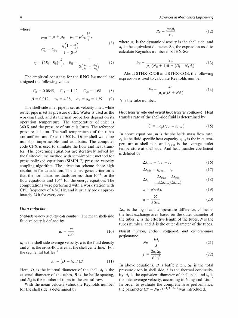
Table 1. Common geometry parameters for three models.
Item Dimensions
Baffle pitch, B (mm) 166Effective tube length, L (mm) 600Shell diameter, Di (mm) 95Tube central distance, Dt (mm) 30Tube outside diameter, dt (mm) 20
Zhang et al. 3
where
meff =m+mt, mt = rCm
k2
e,
C�le =C1e �h 1� h
h0
� �1+bh3
ð6Þ
h= 2Eij � Eij
� �12k
e, Eij =
1
2 ∂ui∂xj
+∂uj∂xi
� � ð7Þ
The empirical constants for the RNG k-e model areassigned the following values
Cm = 0:0845, C1e = 1:42, C2e =1:68 ð8Þ
b= 0:012, h0 = 4:38, ak =ae = 1:39 ð9Þ
The shell-side inlet pipe is set as velocity inlet, whileoutlet pipe is set as pressure outlet. Water is used as theworking fluid, and its thermal properties depend on itsoperation temperature. The temperature of inlet is360K and the pressure of outlet is 0 atm. The referencepressure is 1 atm. The wall temperatures of the tubesare uniform and fixed to 300K. Other shell walls arenon-slip, impermeable, and adiabatic. The computercode CFX is used to simulate the flow and heat trans-fer. The governing equations are iteratively solved bythe finite-volume method with semi-implicit method forpressure-linked equations (SIMPLE) pressure–velocitycoupling algorithm. The advection scheme chose highresolution for calculation. The convergence criterion isthat the normalized residuals are less than 10�6 for theflow equations and 10�8 for the energy equation. Thecomputations were performed with a work station withCPU frequency of 4.8GHz, and it usually took approx-imately 24 h for every case.
Data reduction
Shell-side velocity and Reynolds number. The mean shell-sidefluid velocity is defined by
us =m
rAcð10Þ
us is the shell-side average velocity. r is the fluid densityand Ac is the cross-flow area at the shell centerline.1 Forthe segmental baffles15
Ac = Di � Ncldtð ÞB ð11Þ
Here, Di is the internal diameter of the shell, dt is theexternal diameter of the tubes, B is the baffle spacing,and Ncl is the number of tubes in the central row.
With the mean velocity value, the Reynolds numberfor the shell side is determined by
Re=rusde
ms
ð12Þ
where ms is the dynamic viscosity is the shell side, andde is the equivalent diameter. So, the expression used tocalculate Reynolds number in STHX-SG
Re=2m
ms Ncl + 1ð ÞB+ Di � Ncldtð Þ½ � ð13Þ
About STHX-SCOB and STHX-COB, the followingexpression is used to calculate Reynolds number
Re=4m
msp Di +Ndtð Þ ð14Þ
N is the tube number.
Heat transfer rate and overall heat transfer coefficient. Heattransfer rate of the shell-side fluid is determined by
[=mcp ts, in � ts, outð Þ ð15Þ
In above equations, m is the shell-side mass flow rate,cp is the fluid specific heat capacity, ts, in is the inlet tem-perature at shell side, and ts, out is the average outlettemperature at shell side. And heat transfer coefficientis defined by
Dtmax= ts, in � tw ð16Þ
Dtmin = ts, out � tw ð17Þ
Dtm =Dtmax � Dtmin
ln Dtmax=Dtminð Þ ð18Þ
A=NpdtL ð19Þ
h=[
ADtmð20Þ
Dtm is the log mean temperature difference, A meansthe heat exchange area based on the outer diameter ofthe tubes, L is the effective length of the tubes, N is thetubes number, and dt is the outer diameter of the tubes.
Nusselt number, friction coefficient, and comprehensiveperformance
Nu=hde
lð21Þ
f =2deDp
rLu2ið22Þ
In above equations, B is baffle pitch, Dp is the totalpressure drop in shell side, l is the thermal conductiv-ity, de is the equivalent diameter of shell side, and ui isthe inlet average velocity, according to Yang and Liu.16
In order to evaluate the comprehensive performance,the parameter CP=Nu � f �1=3 14,17 was introduced.
4 Advances in Mechanical Engineering
Model validation
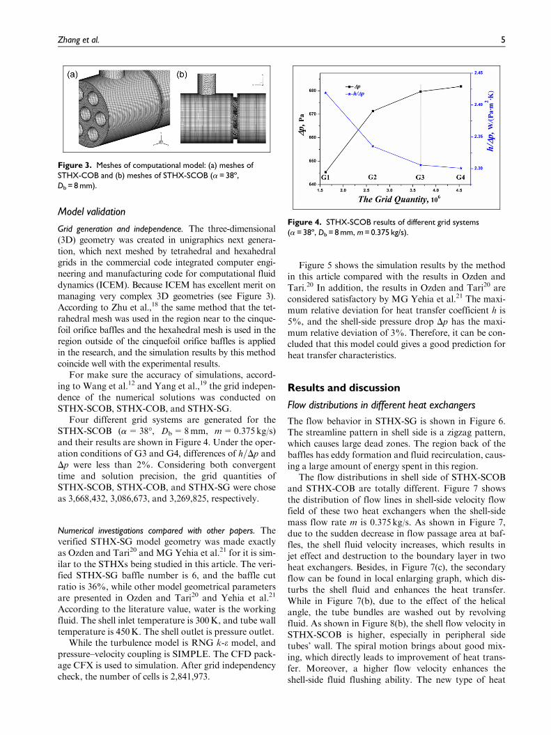
Grid generation and independence. The three-dimensional(3D) geometry was created in unigraphics next genera-tion, which next meshed by tetrahedral and hexahedralgrids in the commercial code integrated computer engi-neering and manufacturing code for computational fluiddynamics (ICEM). Because ICEM has excellent merit onmanaging very complex 3D geometries (see Figure 3).According to Zhu et al.,18 the same method that the tet-rahedral mesh was used in the region near to the cinque-foil orifice baffles and the hexahedral mesh is used in theregion outside of the cinquefoil orifice baffles is appliedin the research, and the simulation results by this methodcoincide well with the experimental results.
For make sure the accuracy of simulations, accord-ing to Wang et al.12 and Yang et al.,19 the grid indepen-dence of the numerical solutions was conducted onSTHX-SCOB, STHX-COB, and STHX-SG.
Four different grid systems are generated for theSTHX-SCOB (a=38�, Db=8mm, m=0.375kg/s)and their results are shown in Figure 4. Under the oper-ation conditions of G3 and G4, differences of h=Dp andDp were less than 2%. Considering both convergenttime and solution precision, the grid quantities ofSTHX-SCOB, STHX-COB, and STHX-SG were choseas 3,668,432, 3,086,673, and 3,269,825, respectively.
Numerical investigations compared with other papers. Theverified STHX-SG model geometry was made exactlyas Ozden and Tari20 and MG Yehia et al.21 for it is sim-ilar to the STHXs being studied in this article. The veri-fied STHX-SG baffle number is 6, and the baffle cutratio is 36%, while other model geometrical parametersare presented in Ozden and Tari20 and Yehia et al.21
According to the literature value, water is the workingfluid. The shell inlet temperature is 300K, and tube walltemperature is 450K. The shell outlet is pressure outlet.
While the turbulence model is RNG k-e model, andpressure–velocity coupling is SIMPLE. The CFD pack-age CFX is used to simulation. After grid independencycheck, the number of cells is 2,841,973.
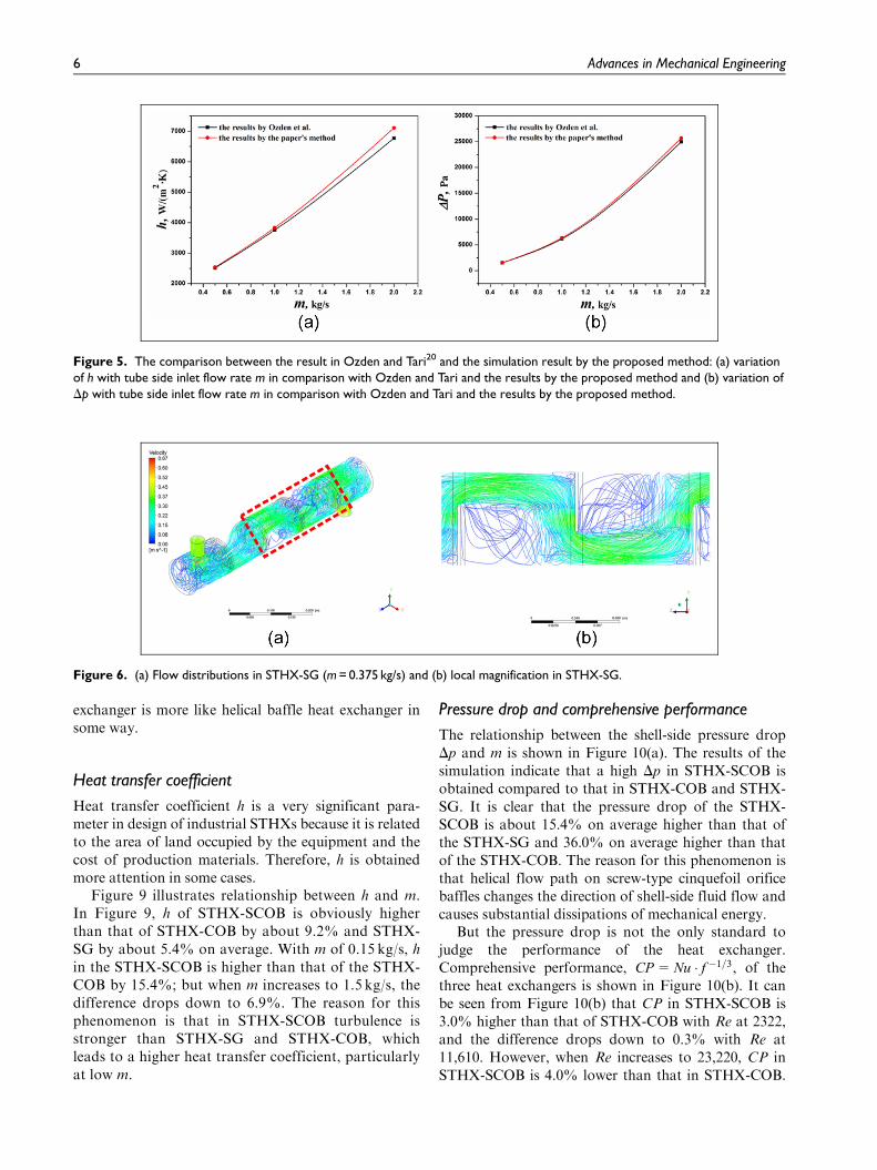
Figure 5 shows the simulation results by the methodin this article compared with the results in Ozden andTari.20 In addition, the results in Ozden and Tari20 areconsidered satisfactory by MG Yehia et al.21 The maxi-mum relative deviation for heat transfer coefficient h is5%, and the shell-side pressure drop Dp has the maxi-mum relative deviation of 3%. Therefore, it can be con-cluded that this model could gives a good prediction forheat transfer characteristics.
Results and discussion
Flow distributions in different heat exchangers
The flow behavior in STHX-SG is shown in Figure 6.The streamline pattern in shell side is a zigzag pattern,which causes large dead zones. The region back of thebaffles has eddy formation and fluid recirculation, caus-ing a large amount of energy spent in this region.
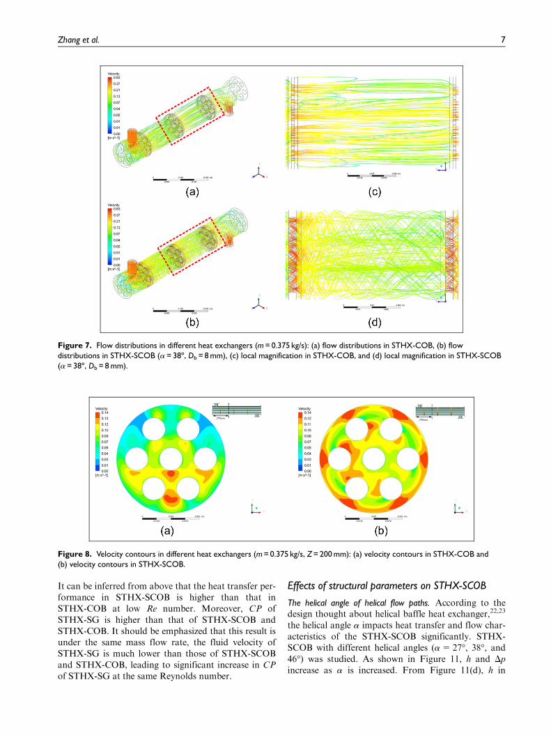
The flow distributions in shell side of STHX-SCOBand STHX-COB are totally different. Figure 7 showsthe distribution of flow lines in shell-side velocity flowfield of these two heat exchangers when the shell-sidemass flow rate m is 0.375 kg/s. As shown in Figure 7,due to the sudden decrease in flow passage area at baf-fles, the shell fluid velocity increases, which results injet effect and destruction to the boundary layer in twoheat exchangers. Besides, in Figure 7(c), the secondaryflow can be found in local enlarging graph, which dis-turbs the shell fluid and enhances the heat transfer.While in Figure 7(b), due to the effect of the helicalangle, the tube bundles are washed out by revolvingfluid. As shown in Figure 8(b), the shell flow velocity inSTHX-SCOB is higher, especially in peripheral sidetubes’ wall. The spiral motion brings about good mix-ing, which directly leads to improvement of heat trans-fer. Moreover, a higher flow velocity enhances theshell-side fluid flushing ability. The new type of heat
Figure 3. Meshes of computational model: (a) meshes ofSTHX-COB and (b) meshes of STHX-SCOB (a = 38º,Db = 8 mm).
Figure 4. STHX-SCOB results of different grid systems(a = 38º, Db = 8 mm, m = 0.375 kg/s).
Zhang et al. 5
exchanger is more like helical baffle heat exchanger insome way.
Heat transfer coefficient
Heat transfer coefficient h is a very significant para-meter in design of industrial STHXs because it is relatedto the area of land occupied by the equipment and thecost of production materials. Therefore, h is obtainedmore attention in some cases.
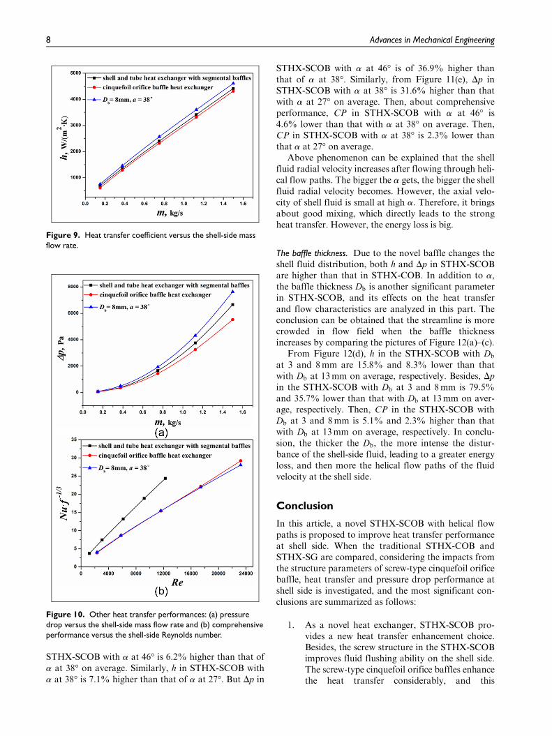
Figure 9 illustrates relationship between h and m.In Figure 9, h of STHX-SCOB is obviously higherthan that of STHX-COB by about 9.2% and STHX-SG by about 5.4% on average. With m of 0.15 kg/s, hin the STHX-SCOB is higher than that of the STHX-COB by 15.4%; but when m increases to 1.5 kg/s, thedifference drops down to 6.9%. The reason for thisphenomenon is that in STHX-SCOB turbulence isstronger than STHX-SG and STHX-COB, whichleads to a higher heat transfer coefficient, particularlyat low m.
Pressure drop and comprehensive performance
The relationship between the shell-side pressure dropDp and m is shown in Figure 10(a). The results of thesimulation indicate that a high Dp in STHX-SCOB isobtained compared to that in STHX-COB and STHX-SG. It is clear that the pressure drop of the STHX-SCOB is about 15.4% on average higher than that ofthe STHX-SG and 36.0% on average higher than thatof the STHX-COB. The reason for this phenomenon isthat helical flow path on screw-type cinquefoil orificebaffles changes the direction of shell-side fluid flow andcauses substantial dissipations of mechanical energy.
But the pressure drop is not the only standard tojudge the performance of the heat exchanger.Comprehensive performance, CP=Nu � f �1=3, of thethree heat exchangers is shown in Figure 10(b). It canbe seen from Figure 10(b) that CP in STHX-SCOB is3.0% higher than that of STHX-COB with Re at 2322,and the difference drops down to 0.3% with Re at11,610. However, when Re increases to 23,220, CP inSTHX-SCOB is 4.0% lower than that in STHX-COB.
Figure 5. The comparison between the result in Ozden and Tari20 and the simulation result by the proposed method: (a) variationof h with tube side inlet flow rate m in comparison with Ozden and Tari and the results by the proposed method and (b) variation ofDp with tube side inlet flow rate m in comparison with Ozden and Tari and the results by the proposed method.
Figure 6. (a) Flow distributions in STHX-SG (m = 0.375 kg/s) and (b) local magnification in STHX-SG.
6 Advances in Mechanical Engineering
It can be inferred from above that the heat transfer per-formance in STHX-SCOB is higher than that inSTHX-COB at low Re number. Moreover, CP ofSTHX-SG is higher than that of STHX-SCOB andSTHX-COB. It should be emphasized that this result isunder the same mass flow rate, the fluid velocity ofSTHX-SG is much lower than those of STHX-SCOBand STHX-COB, leading to significant increase in CPof STHX-SG at the same Reynolds number.
Effects of structural parameters on STHX-SCOB
The helical angle of helical flow paths. According to thedesign thought about helical baffle heat exchanger,22,23
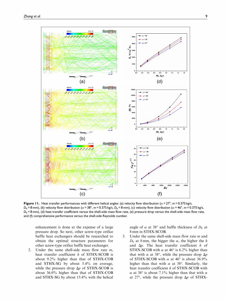
the helical angle a impacts heat transfer and flow char-acteristics of the STHX-SCOB significantly. STHX-SCOB with different helical angles (a=27�, 38�, and46�) was studied. As shown in Figure 11, h and Dp
increase as a is increased. From Figure 11(d), h in
Figure 7. Flow distributions in different heat exchangers (m = 0.375 kg/s): (a) flow distributions in STHX-COB, (b) flowdistributions in STHX-SCOB (a = 38º, Db = 8 mm), (c) local magnification in STHX-COB, and (d) local magnification in STHX-SCOB(a = 38º, Db = 8 mm).
Figure 8. Velocity contours in different heat exchangers (m = 0.375 kg/s, Z = 200 mm): (a) velocity contours in STHX-COB and(b) velocity contours in STHX-SCOB.
Zhang et al. 7
STHX-SCOB with a at 46� is 6.2% higher than that ofa at 38� on average. Similarly, h in STHX-SCOB witha at 38� is 7.1% higher than that of a at 27�. But Dp in
STHX-SCOB with a at 46� is of 36.9% higher thanthat of a at 38�. Similarly, from Figure 11(e), Dp inSTHX-SCOB with a at 38� is 31.6% higher than thatwith a at 27� on average. Then, about comprehensiveperformance, CP in STHX-SCOB with a at 46� is4.6% lower than that with a at 38� on average. Then,CP in STHX-SCOB with a at 38� is 2.3% lower thanthat a at 27� on average.
Above phenomenon can be explained that the shellfluid radial velocity increases after flowing through heli-cal flow paths. The bigger the a gets, the bigger the shellfluid radial velocity becomes. However, the axial velo-city of shell fluid is small at high a. Therefore, it bringsabout good mixing, which directly leads to the strongheat transfer. However, the energy loss is big.
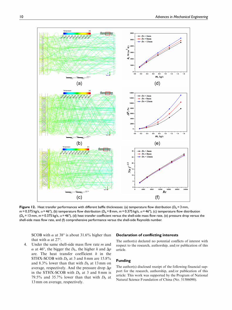
The baffle thickness. Due to the novel baffle changes theshell fluid distribution, both h and Dp in STHX-SCOBare higher than that in STHX-COB. In addition to a,the baffle thickness Db is another significant parameterin STHX-SCOB, and its effects on the heat transferand flow characteristics are analyzed in this part. Theconclusion can be obtained that the streamline is morecrowded in flow field when the baffle thicknessincreases by comparing the pictures of Figure 12(a)–(c).
From Figure 12(d), h in the STHX-SCOB with Db
at 3 and 8mm are 15.8% and 8.3% lower than thatwith Db at 13mm on average, respectively. Besides, Dp
in the STHX-SCOB with Db at 3 and 8mm is 79.5%and 35.7% lower than that with Db at 13mm on aver-age, respectively. Then, CP in the STHX-SCOB withDb at 3 and 8mm is 5.1% and 2.3% higher than thatwith Db at 13mm on average, respectively. In conclu-sion, the thicker the Db, the more intense the distur-bance of the shell-side fluid, leading to a greater energyloss, and then more the helical flow paths of the fluidvelocity at the shell side.
Conclusion
In this article, a novel STHX-SCOB with helical flowpaths is proposed to improve heat transfer performanceat shell side. When the traditional STHX-COB andSTHX-SG are compared, considering the impacts fromthe structure parameters of screw-type cinquefoil orificebaffle, heat transfer and pressure drop performance atshell side is investigated, and the most significant con-clusions are summarized as follows:
1. As a novel heat exchanger, STHX-SCOB pro-vides a new heat transfer enhancement choice.Besides, the screw structure in the STHX-SCOBimproves fluid flushing ability on the shell side.The screw-type cinquefoil orifice baffles enhancethe heat transfer considerably, and this
Figure 9. Heat transfer coefficient versus the shell-side massflow rate.
Figure 10. Other heat transfer performances: (a) pressuredrop versus the shell-side mass flow rate and (b) comprehensiveperformance versus the shell-side Reynolds number.
8 Advances in Mechanical Engineering
enhancement is done at the expense of a largepressure drop. So next, other screw-type orificebaffle heat exchangers should be researched toobtain the optimal structure parameters forother screw-type orifice baffle heat exchanger.
2. Under the same shell-side mass flow rate m,heat transfer coefficient h of STHX-SCOB isabout 9.2% higher than that of STHX-COBand STHX-SG by about 5.4% on average,while the pressure drop Dp of STHX-SCOB isabout 36.0% higher than that of STHX-COBand STHX-SG by about 15.4% with the helical
angle of a at 38� and baffle thickness of Db at8mm in STHX-SCOB.
3. Under the same shell-side mass flow rate m andDb at 8mm, the bigger the a, the higher the hand Dp. The heat transfer coefficient h ofSTHX-SCOB with a at 46� is 6.2% higher thanthat with a at 38�, while the pressure drop Dp
of STHX-SCOB with a at 46� is about 36.9%higher than that with a at 38�. Similarly, theheat transfer coefficient h of STHX-SCOB witha at 38� is about 7.1% higher than that with a
at 27�, while the pressure drop Dp of STHX-
Figure 11. Heat transfer performances with different helical angles: (a) velocity flow distribution (a = 27º, m = 0.375 kg/s,Db = 8 mm), (b) velocity flow distribution (a = 38º, m = 0.375 kg/s, Db = 8 mm), (c) velocity flow distribution (a = 46º, m = 0.375 kg/s,Db = 8 mm), (d) heat transfer coefficient versus the shell-side mass flow rate, (e) pressure drop versus the shell-side mass flow rate,and (f) comprehensive performance versus the shell-side Reynolds number.
Zhang et al. 9
SCOB with a at 38� is about 31.6% higher thanthat with a at 27�.
4. Under the same shell-side mass flow rate m anda at 46�, the bigger the Db, the higher h and Dp
are. The heat transfer coefficient h in theSTHX-SCOB with Db at 3 and 8mm are 15.8%and 8.3% lower than that with Db at 13mm onaverage, respectively. And the pressure drop Dp
in the STHX-SCOB with Db at 3 and 8mm is79.5% and 35.7% lower than that with Db at13mm on average, respectively.
Declaration of conflicting interests
The author(s) declared no potential conflicts of interest withrespect to the research, authorship, and/or publication of thisarticle.
Funding
The author(s) disclosed receipt of the following financial sup-port for the research, authorship, and/or publication of thisarticle: This work was supported by the Program of NationalNatural Science Foundation of China (No. 51506090).
Figure 12. Heat transfer performances with different baffle thicknesses: (a) temperature flow distribution (Db = 3 mm,m = 0.375 kg/s, a= 46º), (b) temperature flow distribution (Db = 8 mm, m = 0.375 kg/s, a= 46º), (c) temperature flow distribution(Db = 13 mm, m = 0.375 kg/s, a= 46º), (d) heat transfer coefficient versus the shell-side mass flow rate, (e) pressure drop versus theshell-side mass flow rate, and (f) comprehensive performance versus the shell-side Reynolds number.
10 Advances in Mechanical Engineering
References
1. El Maakoul A, Laknizi A, Saadeddine S, et al. Numeri-
cal comparison of shell-side performance for shell and
tube heat exchangers with trefoil-hole, helical and seg-
mental baffles. Appl Therm Eng 2016; 109: 175–185.2. Li HD and Kottke V. Effect of the leakage on pressure
drop and local heat transfer in shell-and-tube heat
exchangers for staggered tube arrangement. Int J Heat
Mass Tran 1998; 41: 425–433.3. Gu X, Liu B, Wang Y, et al. Heat transfer and flow resis-
tance performance of shutter baffle heat exchanger with
triangle tube layout in shell side. Adv Mech Eng 2016; 8:
1–8.4. Guo J, Xu M and Cheng L. The application of field
synergy number in shell-and-tube heat exchanger optimi-
zation design. Appl Energ 2009; 86: 2079–2087.5. Gentry CC. Rod baffle heat exchanger technology. Chem
Eng Prog 1990; 86: 48–56.6. You Y, Fan A, Lai X, et al. Experimental and numerical
investigations of shell-side thermo-hydraulic perfor-
mances for shell-and-tube heat exchanger with trefoil-
hole baffles. Appl Therm Eng 2013; 50: 950–956.7. Zhou GY, Xiao J, Zhu L, et al. A numerical study on
the shell-side turbulent heat transfer enhancement of
shell-and-tube heat exchanger with trefoil-hole baffles.
Enrgy Proced 2015; 75: 3174–3179.8. You Y, Chen Y, Xie M, et al. Numerical simulation and
performance improvement for a small size shell-and-tube
heat exchanger with trefoil-hole baffles. Appl Therm Eng
2015; 89: 220–228.9. Zhang JF, Li B, Huang WJ, et al. Experimental perfor-
mance comparison of shell-side heat transfer for shell-
and-tube heat exchangers with middle-overlapped helical
baffles and segmental baffles. Chem Eng Sci 2009; 64:
1643–1653.10. Lutcha J and Nemcansky J. Performance improvement of
tubular heat exchangers by helical baffles. Chem Eng Res
Des 1990; 68: 263–270.11. Wang S, Wen J, Yang H, et al. Experimental investiga-
tion on heat transfer enhancement of a heat exchanger
with helical baffles through blockage of triangle leakage
zones. Appl Therm Eng 2014; 67: 122–130.12. Wang Q, Chen Q, Chen G, et al. Numerical investigation
on combined multiple shell-pass shell-and-tube heat
exchanger with continuous helical baffles. Int J Heat
Mass Tran 2009; 52: 1214–1222.13. Yakhot V and Orszag SA. Renormalization-group analy-
sis of turbulence. Phys Rev Lett 1986; 57: 1722–1724.14. Jian W, Huizhu Y, Wang S, et al. Numerical investigation
on baffle configuration improvement of the heat exchan-
ger with helical baffles. Energ Convers Manage 2015; 89:
438–448.15. Eduardo C. Heat transfer in process engineering. New
York: McGraw-Hill Publishing Company, 2009.16. Yang J and Liu W. Numerical investigation on a novel
shell-and-tube heat exchanger with plate baffles and
experimental validation. Energ Convers Manage 2015;
101: 689–696.17. Zhang JF, He YL and Tao WQ. 3D numerical simula-
tion on shell-and-tube heat exchangers with middle-
overlapped helical baffles and continuous baffles—part I:numerical model and results of whole heat exchangerwith middle-overlapped helical baffles. Int J Heat Mass
Tran 2009; 52: 5371–5380.18. Zhu LY, Lang HF, Zhou G, et al. Numerical simulation
on shell side fluid flow and heat transfer in heat exchan-ger with trefoil-baffles. CIESC J 2014; 65: 829–835 (inChinese).
19. Yang JF, Zeng M and Wang QW. Numerical investiga-tion on combined single shell-pass shell-and-tube heatexchanger with two-layer continuous helical baffles. Int JHeat Mass Tran 2015; 84: 103–113.
20. Ozden E and Tari I. Shell side CFD analysis of a small
shell-and-tube heat exchanger. Energ Convers Manage
2010; 51: 1004–1014.21. Yehia MG, Attia AA, Abdelatif OE, et al. Computa-
tional investigations of thermal simulation of shell and
tube heat exchanger. In: Proceedings of the ASME 2014
12th biennial conference on engineering systems design and
analysis, Copenhagen, 25–27 July 2014, p.V003T12A001.New York: ASME.
22. Yang JF, Lin YS, Ke HB, et al. Investigation on com-bined multiple shell-pass shell-and-tube heat exchangerwith continuous helical baffles. Energy 2016; 115:1572–1579.
23. Lei YG, He YL, Li R, et al. Effects of baffle inclinationangle on flow and heat transfer of a heat exchanger withhelical baffles. Chem Eng Process 2008; 47: 2336–2345.
Appendix 1
Notation
A heat transfer area (m2)Ac cross-flow area at the shell centerline (m2)B baffle pitch (m)Cp specific heat capacity (J/(kgK))CP comprehensive performancede equivalent diameter (m)do outer diameter of orifice (mm)dt tube outside diameter (mm)Db baffle thickness (mm)Di internal shell diameter (mm)Dt tube central distance (mm)f friction coefficienth average heat transfer coefficient
(W=m2 K)k turbulent fluctuation kinetic energy
(m2=s2)L total effective tube length (mm)m shell side mass flow rate (kg/s)N number of tubesNcl number of tubes in the central rowNu Nusselt numberDp pressure drop (Pa)Re Reynolds numberDtm logarithmic mean temperature
difference (K)
Zhang et al. 11

ts, in,ts, out
temperature of inlet tube and outlettube (K)
tw tube wall temperature (K)u, v, w velocities in different directions (m/s)ui inlet average velocity (m/s)us shell side average velocity (m/s)x, y, z Cartesian coordinate
a helical angle of helical flow paths (�)b cinquefoil orifice angle (�)
e turbulent kinetic energy dissipation rate(m2=s3)
m dynamic viscosity (kg/(m s))mt turbulent dynamic viscosity (kg/(m s))l thermal conductivity (W/(mK))r fluid density (kg=m3)[ heat transfer quantity (W)
12 Advances in Mechanical Engineering