
Numerical studies of a tube-in-tube helically coiled heat exchanger
9
Available online at www.sciencedirect.com Chemical Engineering and Processing 47 (2008) 2287–2295 Numerical studies of a tube-in-tube helically coiled heat exchanger Vimal Kumar, Burhanuddin Faizee, Monisha Mridha, K.D.P. Nigam ∗ Department of Chemical Engineering, Indian Institute of Technology, Delhi, Hauz Khas, New Delhi-110016, India Received 6 August 2007; received in revised form 29 December 2007; accepted 2 January 2008 Available online 11 January 2008 Abstract In the present study a tube-in-tube helically coiled (TTHC) heat exchanger has been numerically modeled for fluid flow and heat transfer characteristics for different fluid flow rates in the inner as well as outer tube. The three-dimensional governing equations for mass, momentum and heat transfer have been solved using a control volume finite difference method (CVFDM). The renormalization group (RNG) k–ε model is used to model the turbulent flow and heat transfer in the TTHC heat exchanger. The fluid considered in the inner tube is compressed air at higher pressure and cooling water in the outer tube at ambient conditions. The inner tube pressure is varied from 10 to 30 bars. The Reynolds numbers for the inner tube ranged from 20,000 to 70,000. The mass flow rate in the outer tube is varied from 200 to 600 kg/h. The outer tube is fitted with semicircular plates to support the inner tube and also to provide high turbulence in the annulus region. The overall heat transfer coefficients are calculated for both parallel and counter flow configurations. The Nusselt number and friction factor values in the inner and outer tubes are compared with the experimental data reported in the literature. New empirical correlations are developed for hydrodynamic and heat-transfer predictions in the outer tube of the TTHC. © 2008 Elsevier B.V. All rights reserved. Keywords: Tube-in-tube helical heat exchanger; Heat transfer; Helical tube; RNG k– 1. Introduction Helical coil heat exchangers are one of the most com- mon equipment found in many industrial applications ranging from chemical and food industries, power production, elec- tronics, environmental engineering, manufacturing industry, air-conditioning, waste heat recovery, cryogenic processes, and space applications. Helical coils are extensively used as heat exchangers and reactors due to higher heat and mass transfer coefficients, narrow residence time distributions and compact structure. The modification of the flow in the helically coiled tubes is due to the centrifugal forces (Dean roll cells, [4,5]). The curvature of the tube produces a secondary flow field with a cir- culatory motion, which causes the fluid particles to move toward the core region of the tube. The secondary flow enhances heat transfer rates as it reduces the temperature gradient across the cross-section of the tube. Thus there is an additional convective Abbreviations: CVFDM, control volume finite difference method; HVAC, heating, ventilating and air conditioning; LMTD, log-mean temperature differ- ence; TTHC, tube-in-tube helical coil. ∗ Corresponding author. Tel.: +91 11 26591020; fax: +91 11 26591020. E-mail address: [email protected] (K.D.P. Nigam). heat transfer mechanism, perpendicular to the main flow, which does not exist in conventional heat exchangers. An extensive review of fluid flow and heat transfer in helical pipes has been presented in the literature [1–3]. There is considerable amount of work reported in the lit- erature on heat transfer in coiled tubes; however, very less attention has been paid to study the outer heat transfer coef- ficient. Figueiredo and Raimunda [6], Haraburda [7], Prasad et al. [8] and Patil et al. [9] have discussed the design procedure for coil-in-shell heat exchangers considering helical coiled tubes as a bank of straight tubes for calculating outer heat transfer coef- ficients. In the coil-in-shell heat exchangers poor circulation is observed in shell regions near the coil which could be avoided by using a tube-in-tube helical coil (TTHC) configuration. A tube-in-tube helical coil heat exchanger requires the knowledge of the heat transfer rates for the two flowing fluid, i.e., the flow in the helical tube as well as in the helical annulus. Karahalios [10] and Petrakis and Karahalios [11–13] reported the fluid flow and heat transfer in a curved pipe with a solid core. They showed that the size of the core affects the flow in the annulus with flows approaching parabolic for large cores [13]. Karahalios [10] studied the heat transfer in a curved annulus with a constant tem- perature gradient on both inner and outer walls of the annulus as 0255-2701/$ – see front matter © 2008 Elsevier B.V. All rights reserved. doi:10.1016/j.cep.2008.01.001
-
Upload
independent -
Category
Documents
-
view
0 -
download
0
Transcript of Numerical studies of a tube-in-tube helically coiled heat exchanger
A
chmatpbet©
K
1
mftasecstccttc
he
0d
Available online at www.sciencedirect.com
Chemical Engineering and Processing 47 (2008) 2287–2295
Numerical studies of a tube-in-tube helically coiled heat exchanger
Vimal Kumar, Burhanuddin Faizee, Monisha Mridha, K.D.P. Nigam ∗Department of Chemical Engineering, Indian Institute of Technology, Delhi, Hauz Khas, New Delhi-110016, India
Received 6 August 2007; received in revised form 29 December 2007; accepted 2 January 2008Available online 11 January 2008
bstract
In the present study a tube-in-tube helically coiled (TTHC) heat exchanger has been numerically modeled for fluid flow and heat transferharacteristics for different fluid flow rates in the inner as well as outer tube. The three-dimensional governing equations for mass, momentum andeat transfer have been solved using a control volume finite difference method (CVFDM). The renormalization group (RNG) k–ε model is used toodel the turbulent flow and heat transfer in the TTHC heat exchanger. The fluid considered in the inner tube is compressed air at higher pressure
nd cooling water in the outer tube at ambient conditions. The inner tube pressure is varied from 10 to 30 bars. The Reynolds numbers for the innerube ranged from 20,000 to 70,000. The mass flow rate in the outer tube is varied from 200 to 600 kg/h. The outer tube is fitted with semicircularlates to support the inner tube and also to provide high turbulence in the annulus region. The overall heat transfer coefficients are calculated for
oth parallel and counter flow configurations. The Nusselt number and friction factor values in the inner and outer tubes are compared with thexperimental data reported in the literature. New empirical correlations are developed for hydrodynamic and heat-transfer predictions in the outerube of the TTHC.2008 Elsevier B.V. All rights reserved.
G k–
hdrp
eafiacafiob
eywords: Tube-in-tube helical heat exchanger; Heat transfer; Helical tube; RN
. Introduction
Helical coil heat exchangers are one of the most com-on equipment found in many industrial applications ranging
rom chemical and food industries, power production, elec-ronics, environmental engineering, manufacturing industry,ir-conditioning, waste heat recovery, cryogenic processes, andpace applications. Helical coils are extensively used as heatxchangers and reactors due to higher heat and mass transferoefficients, narrow residence time distributions and compacttructure. The modification of the flow in the helically coiledubes is due to the centrifugal forces (Dean roll cells, [4,5]). Theurvature of the tube produces a secondary flow field with a cir-ulatory motion, which causes the fluid particles to move toward
he core region of the tube. The secondary flow enhances heatransfer rates as it reduces the temperature gradient across theross-section of the tube. Thus there is an additional convectiveAbbreviations: CVFDM, control volume finite difference method; HVAC,eating, ventilating and air conditioning; LMTD, log-mean temperature differ-nce; TTHC, tube-in-tube helical coil.∗ Corresponding author. Tel.: +91 11 26591020; fax: +91 11 26591020.
E-mail address: [email protected] (K.D.P. Nigam).
totahtflsp
255-2701/$ – see front matter © 2008 Elsevier B.V. All rights reserved.oi:10.1016/j.cep.2008.01.001
�
eat transfer mechanism, perpendicular to the main flow, whichoes not exist in conventional heat exchangers. An extensiveeview of fluid flow and heat transfer in helical pipes has beenresented in the literature [1–3].
There is considerable amount of work reported in the lit-rature on heat transfer in coiled tubes; however, very lessttention has been paid to study the outer heat transfer coef-cient. Figueiredo and Raimunda [6], Haraburda [7], Prasad etl. [8] and Patil et al. [9] have discussed the design procedure foroil-in-shell heat exchangers considering helical coiled tubes asbank of straight tubes for calculating outer heat transfer coef-cients. In the coil-in-shell heat exchangers poor circulation isbserved in shell regions near the coil which could be avoidedy using a tube-in-tube helical coil (TTHC) configuration. Aube-in-tube helical coil heat exchanger requires the knowledgef the heat transfer rates for the two flowing fluid, i.e., the flow inhe helical tube as well as in the helical annulus. Karahalios [10]nd Petrakis and Karahalios [11–13] reported the fluid flow andeat transfer in a curved pipe with a solid core. They showed
hat the size of the core affects the flow in the annulus withows approaching parabolic for large cores [13]. Karahalios [10]tudied the heat transfer in a curved annulus with a constant tem-erature gradient on both inner and outer walls of the annulus as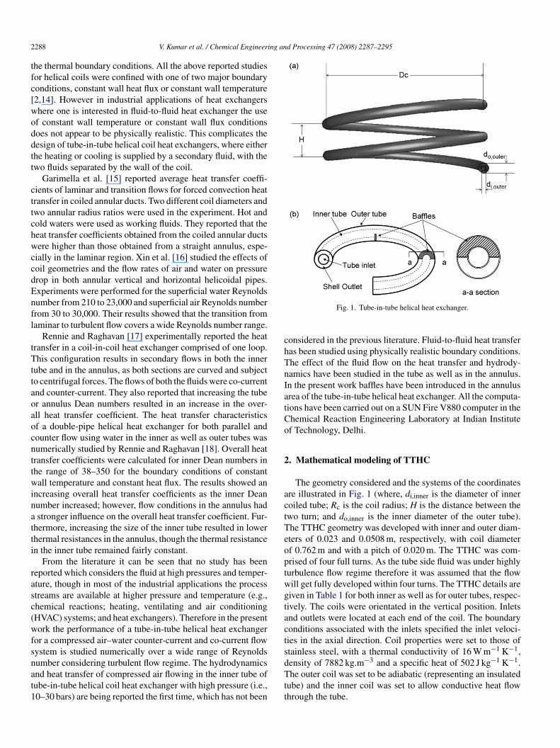
2 ing and Processing 47 (2008) 2287–2295
tfc[woddtt
cttchwccdEnfl
tTttaoaocnttwinatti
rasc(wfsnat1
chTnIatCo
2
actTeoptwgtacts
288 V. Kumar et al. / Chemical Engineer
he thermal boundary conditions. All the above reported studiesor helical coils were confined with one of two major boundaryonditions, constant wall heat flux or constant wall temperature2,14]. However in industrial applications of heat exchangershere one is interested in fluid-to-fluid heat exchanger the usef constant wall temperature or constant wall flux conditionsoes not appear to be physically realistic. This complicates theesign of tube-in-tube helical coil heat exchangers, where eitherhe heating or cooling is supplied by a secondary fluid, with thewo fluids separated by the wall of the coil.
Garimella et al. [15] reported average heat transfer coeffi-ients of laminar and transition flows for forced convection heatransfer in coiled annular ducts. Two different coil diameters andwo annular radius ratios were used in the experiment. Hot andold waters were used as working fluids. They reported that theeat transfer coefficients obtained from the coiled annular ductsere higher than those obtained from a straight annulus, espe-
ially in the laminar region. Xin et al. [16] studied the effects ofoil geometries and the flow rates of air and water on pressurerop in both annular vertical and horizontal helicoidal pipes.xperiments were performed for the superficial water Reynoldsumber from 210 to 23,000 and superficial air Reynolds numberrom 30 to 30,000. Their results showed that the transition fromaminar to turbulent flow covers a wide Reynolds number range.
Rennie and Raghavan [17] experimentally reported the heatransfer in a coil-in-coil heat exchanger comprised of one loop.his configuration results in secondary flows in both the inner
ube and in the annulus, as both sections are curved and subjecto centrifugal forces. The flows of both the fluids were co-currentnd counter-current. They also reported that increasing the tuber annulus Dean numbers resulted in an increase in the over-ll heat transfer coefficient. The heat transfer characteristicsf a double-pipe helical heat exchanger for both parallel andounter flow using water in the inner as well as outer tubes wasumerically studied by Rennie and Raghavan [18]. Overall heatransfer coefficients were calculated for inner Dean numbers inhe range of 38–350 for the boundary conditions of constantall temperature and constant heat flux. The results showed an
ncreasing overall heat transfer coefficients as the inner Deanumber increased; however, flow conditions in the annulus hadstronger influence on the overall heat transfer coefficient. Fur-
hermore, increasing the size of the inner tube resulted in lowerhermal resistances in the annulus, though the thermal resistancen the inner tube remained fairly constant.
From the literature it can be seen that no study has beeneported which considers the fluid at high pressures and temper-ture, though in most of the industrial applications the processtreams are available at higher pressure and temperature (e.g.,hemical reactions; heating, ventilating and air conditioningHVAC) systems; and heat exchangers). Therefore in the presentork the performance of a tube-in-tube helical heat exchanger
or a compressed air–water counter-current and co-current flowystem is studied numerically over a wide range of Reynolds
umber considering turbulent flow regime. The hydrodynamicsnd heat transfer of compressed air flowing in the inner tube ofube-in-tube helical coil heat exchanger with high pressure (i.e.,0–30 bars) are being reported the first time, which has not beendTtt
Fig. 1. Tube-in-tube helical heat exchanger.
onsidered in the previous literature. Fluid-to-fluid heat transferas been studied using physically realistic boundary conditions.he effect of the fluid flow on the heat transfer and hydrody-amics have been studied in the tube as well as in the annulus.n the present work baffles have been introduced in the annulusrea of the tube-in-tube helical heat exchanger. All the computa-ions have been carried out on a SUN Fire V880 computer in thehemical Reaction Engineering Laboratory at Indian Institutef Technology, Delhi.
. Mathematical modeling of TTHC
The geometry considered and the systems of the coordinatesre illustrated in Fig. 1 (where, di,inner is the diameter of inneroiled tube; Rc is the coil radius; H is the distance between thewo turn; and do,inner is the inner diameter of the outer tube).he TTHC geometry was developed with inner and outer diam-ters of 0.023 and 0.0508 m, respectively, with coil diameterf 0.762 m and with a pitch of 0.020 m. The TTHC was com-rised of four full turns. As the tube side fluid was under highlyurbulence flow regime therefore it was assumed that the flowill get fully developed within four turns. The TTHC details areiven in Table 1 for both inner as well as for outer tubes, respec-ively. The coils were orientated in the vertical position. Inletsnd outlets were located at each end of the coil. The boundaryonditions associated with the inlets specified the inlet veloci-ies in the axial direction. Coil properties were set to those oftainless steel, with a thermal conductivity of 16 W m−1 K−1,ensity of 7882 kg.m−3 and a specific heat of 502 J kg−1 K−1.
he outer coil was set to be adiabatic (representing an insulatedube) and the inner coil was set to allow conductive heat flowhrough the tube.
V. Kumar et al. / Chemical Engineering an
Table 1Geometrical and flow parameters for the inner and outer tube of TTHC
Inner tube Outer tube
Outer diameter (m) 0.0254 0.0508Inner diameter (m) 0.023 0.0484Coil diameter (m) 0.762 0.762Pitch (m) 0.100 0.100Number of turns 4 4Flow rate (kg/h) 40–85 200–600PP
ft2dddraTtacprtoac
2
cwctfTdsp
todm[aaTegts
ressure (bars) 10, 20 and 30 1randtl number 1 0.74, 7, 33 and 150
The pressure drop and heat transfer in the TTHC is studiedor five different Reynolds number (30,000 < NRe < 70,000) inhe inner tube. The outer tube mass flow rates is varied from00 to 600 kg/h. The Reynolds number in the outer tube isifferent for pressure drop and heat transfer calculations as itepends upon the equivalent diameter of the outer tube. Theetailed description of the equivalent diameter calculation iseported in Kumar et al. [19]. The simulations were carried outt three different levels of pressure values, i.e., form 10–30 bar.he annulus side fluid properties were calculated at average
emperature i.e., mean of inlet and outlet temperature in thennulus. Compressed air density in the inner tube was cal-ulated using ideal gas law. The total number of simulationserformed were 150 (5 inner tube flow rates, 5 outer tube flowates, 3 operating pressure values and 2 flow arrangement sys-ems). The output of the simulations included the inlet andutlet velocities, mass flow rates and enthalpy rates, as wells velocity, pressure, and temperature fields at various specifiedross-sections.
.1. Governing equations
The geometry, system of coordinates and details of TTHConsidered for the present work are discussed in our previousork [19]. In the TTHC the cold and hot fluids enter from their
orresponding inlets and heat transfer take place between thewo fluids due to conduction and forced convection. Heat trans-er by radiation can be neglected because temperature in theTHC studied is quite low (max. 353 K). The Cartesian coor-inate system (x, y, z) was used to represent flow in numericalimulation. The flow was considered to be steady, and incom-ressible.
At the inlet (φ = 0◦), fluid with turbulence intensity I andemperature T0 enters the TTHC heat exchanger at a velocityf u0. Turbulent flow and heat transfer develop simultaneouslyownstream in the tubes. For the turbulent flow and heat transferodeling the RNG k–� model proposed by Yakhot and Orszag
20] was used in the TTHC because the RNG model included andditional term in its � equation that significantly improve theccuracy for rapidly strained flows, such as those in curved pipes.he effect of swirl on turbulence is included in the RNG model,
nhancing accuracy for swirling flows. The three dimensionaloverning equations of turbulent flow and the heat transfer inhe TTHC can be written in tensor form in the master Cartesianystem as follows:d Processing 47 (2008) 2287–2295 2289
Ideal gas law:
P = ρRT (1)
Continuity equation:
∂ui
∂xi
= 0 (2)
Momentum equation:
∂(ρuiuj)
∂xj
= ∂
∂xj
[μeff
(∂ui
∂xj
+ ∂uj
∂xi
)− 2
3μeff
∂uk
∂xk
]− ∂p
∂xi
(3)
Energy equation:
∂(ρuicpT )
∂xi
= ∂
∂xi
[αT
(μeff
∂T
∂xi
)]+ dui
dxj
[μeff
(∂ui
∂xj
+ ∂uj
∂xi
)
− 2
3μeff
∂uk
∂xk
δij
](4)
Turbulent kinetic energy equation:
∂(ρuik)
∂xi
= ∂
∂xi
[(αkμeff
∂k
∂xi
)]+ μtS
2 + Gb − ρε (5)
Dissipation rate of turbulent kinetic energy equation:
∂(ρuiε)
∂xi
= ∂
∂xi
[(αεμeff
∂ε
∂xi
)]+ C1ε
ε
kμtS
2
− C2ερε2
k− Ra (6)
The effective viscosity, μeff can be defined as
μeff = μmol
(1 +
√Cμ
μmol
k√ε
)2
(7)
where μmol is the molecular viscosity. The coefficients αT,αk and αε in Eqs. (4)–(6) are the inverse effective Prandtlnumbers for T, k, and ε, respectively. The values of inverseeffective Prandtl numbers, αT, αk and αε are computed usingthe following formula derived analytically by the RNG theory:∣∣∣∣ α − 1.3929
α0 − 1.3929
∣∣∣∣0.6321∣∣∣∣ α + 2.3929
α0 + 2.3929
∣∣∣∣0.3679
= μmol
μeff(8)
where α0 is equal to 1/NPr, 1.0, and 1.0, for the computationof αT, αk and αε, respectively. When a non-zero gravity fieldand temperature gradient are present simultaneously, the k–ε
model account for the generation of k (kinetic energy) due tobuoyancy (Gb in Eq. (5)) and the corresponding contribution tothe production of ε (energy dissipation) in Eq. (6). The effectsof buoyancy are also included despite the fact that the effect ofbuoyancy is not so significant at very high Reynolds number.The generation of turbulence due to buoyancy is given by
Gb = βgi
μt
NPr,t
∂T
∂xi
(9)
where NPr,t is the turbulent Prandtl number for energy, gi is thecomponent of the gravitational vector in the ith direction. In the
2 ing an
fnflpigitsw
ui
w
T
N
wlc
w
u
dcide
k
up
0ot
etpv
w
3
3
Twid[
ediraptaffct1
3
tf
U
woAt
290 V. Kumar et al. / Chemical Engineer
case of the RNG k–� model, NPr,t = 1/αT, and β, the coefficientof thermal expansion, is defined as β = −1/ρ(∂p/∂T)T. In Eq.(6), R is given by
R = Cμρη3(1 − η/η0)
1 + ζη3
ε2
k(10)
where η = S k/ε, η0 ≈ 4.38, ζ = 0.012. The model constants C�,C1�, and C2� are equal to 0.085, 1.42 and 1.68, respectively.The term S in Eq. (5) and Eq. (6) is the modulus of the meanrate-of-strain tensor, defined as S =√2SijSij , where
Sij = 1
2
(∂ui
∂xj
+ ∂uj
∂xi
)(11)
The two-layer based, non-equilibrium wall function was usedor the near-wall treatment of flow in the given geometry. Theon-equilibrium wall functions are recommended for complexows because of the capability to partly account for the effects ofressure gradients and departure from equilibrium. The numer-cal results for turbulent flow tend to be more susceptible torid dependency than those for laminar flow due to the strongnteraction of the mean flow and turbulence. The distance fromhe wall at the wall-adjacent cells must be determined by con-idering the range over which the log-law is valid. The size ofall adjacent cells can be estimated from yp( y+
p ν/uτ), where
�≡(τw/ρ)0.5 = u (cf/2)0.5. In the present study, the y+p was taken
n the range of 30–60.The wall heat flux was computed using qw = ρCpu T/T+,
here T+ is obtained from
+ =
⎧⎪⎨⎪⎩
NPr
u
u∗ , y+ ≤ y+v
NPr,w
( u
u∗ − NPr
), y+ > y+
v
(12)
Pr = π/4
sin (π/4)
(AT
κ
)1/2(NPr
NPr,w
− 1
)(NPr,w
NPr
)1/4
(13)
here NPr is the molecular Prandtl number, NPr,w, the turbu-ent wall Prandtl number (NPr,w = 1.2) and AT, the Van Driestonstant (AT = 26).
At the inlet, uniform profiles for all the dependent variablesere employed:
s = u0, T = T0, k = k0, ε = ε0. (14)
For the inner and outer walls of the heat exchanger, heat con-uction in solid wall was considered. Ambient temperature wasonsidered across the outer wall of the TTHC heat exchanger,.e., T = 300 K. Turbulent kinetic energy at the inlet, k0, and theissipation rate of turbulent kinetic energy at the inlet, ε0, werestimated by
0 = 3(u0I)2 ε0 = C3/4 k3/2
(15)
2 μ LIn Eq. (14), the turbulence intensity level, I, is defined as//u × 100%. As the turbulent eddies cannot be larger than theipe, the turbulence characteristic length scale, L, is set to be
atw
d Processing 47 (2008) 2287–2295
.07(di,inner/2) in the present study. The factor of 0.07 is basedn the maximum value of the mixing length in fully developedurbulent pipe flow.
The computation domain (4 turns) used in this study cannsure that the outflow condition (i.e., fully developed flow andhermal assumed) can be satisfied at the exit plane of the curvedipe. Therefore, at the outlet, the diffusion term for all dependentariables were set to zero in the exit direction:
∂φ
∂n= 0 (16)
here φ represents the variables ui, T, k and ε.
. Numerical computation
.1. Numerical method
The governing equations for flow and heat transfer in theTHC were solved in the master Cartesian coordinate systemith a control volume finite difference method (CVFDM) sim-
lar to that introduced by Patankar [21]. The grid topology andensity considered was similar as used in our previous work19].
The convection term in the governing equations was mod-led with the bounded second-order upwind scheme and theiffusion term was computed using multi linear interpolat-ng polynomial nodes. The SIMPLEC algorithm was used toesolve the coupling between velocity and pressure [22]. Toccelerate the convergence, the under-relaxation factor for theressure, p, was 0.3; that for temperature, T, was 0.9; that forhe velocity component in the i-direction, ui, k and ε was 0.7;nd that for body force was 0.8. In order to predict the per-ormance of the TTHC, the double precision solver was usedor simulations. The numerical computation was consideredonverged when the residual summed over all the computa-ional nodes at the nth iteration was less than or equal to0−6.
.2. Calculation of heat transfer coefficient
The overall heat-transfer coefficient, Uo, was calculated fromhe inlet and outlet temperature data and the flow rates, using theollowing equation:
o = q
Ao TLMTD(17)
here TLMTD is the log mean temperature difference. Theverall heat transfer rates were based on the outer surface area,o, of the inner tube. The TLMTD was calculated based on the
emperature difference, T1 and T2 using following equation:
TLMTD = T2 − T1
ln( T2/ T1)(18)
Heat transfer coefficients were calculated for both the innernd outer tubes. For these calculations, average bulk tempera-ures and average temperature of the coil at each cross-sectionere used. The inner and outer heat transfer coefficients are
ing and Processing 47 (2008) 2287–2295 2291
uoite
wot
s[mthm
h
sTlSha
4
tbt
4
ogq
q
wfltfloN
N
a
l
cfu(cc(e
4
a
f
wavtwa
V. Kumar et al. / Chemical Engineer
sually obtained from the overall thermal resistance consistingf three resistances in series: the convective resistance in thenner surface, the conductance resistance of the pipe wall andhe convective resistance on the outer surface by the followingquation:
1
Uo= Ao
Aihi+ Ao ln(do/di)
2πkL+ 1
ho(19)
here do is the outer diameter of the tube; di is the inner diameterf the tube; k is the thermal conductivity of the wall; and L ishe length of the tube.
Heat transfer coefficients for the shell side, ho, and for the tubeide, hi, were calculated using traditional Wilson plot technique17,19]. For the calculation of inner heat transfer coefficient, theass flow rate in the shell side was kept constant; and assumed
hat the outer heat transfer coefficient is constant. The innereat transfer coefficient was assumed to behave in the followinganner with the fluid velocity in the tube side, ui:
i = Cuni (20)
Eq. (20) was placed into Eq. (19) and the values for the con-tant C and the exponent n were determined through curve fitting.he inner and outer heat transfer coefficients could then be calcu-
ated. This procedure was repeated for each outer tube flow rate.imilar procedure was adopted for the calculation of annuluseat transfer coefficient (by keeping tube side flow rate constantnd annulus side flow rate varying).
. Results and discussion
The TTHC heat exchanger was analyzed in terms of heatransfer in downstream length and heat exchanger efficiencyefore discussing the friction factor and fully developed heat-ransfer coefficient in the inner and outer tube, respectively.
.1. Effectiveness-NTU
The effectiveness is defined as the ratio of the actual amountf heat transfer to the maximum possible heat transfer for theiven heat exchanger. The maximum amount of heat transferred,max, is calculated by:
max = Cmin(Tin,h − Tin,c) (21)
here Cmin is the minimum between mcCp,c and mhCp,h (massow rate multiplied by specific heat), Tin,h is the inlet tempera-
ure of the hot fluid, and Tin,c is the inlet temperature of the colduid. The effectiveness is generally plotted vs. the NTUmax tobtain graphs that contain curves of constant Cmin to Cmax ratios.TUmax is defined as:
A U
TUmax = o oCmin(22)
Furthermore, the theoretical effectiveness, ε, for a co-currentnd counter-current flow heat exchangers are given by the fol-
e
f
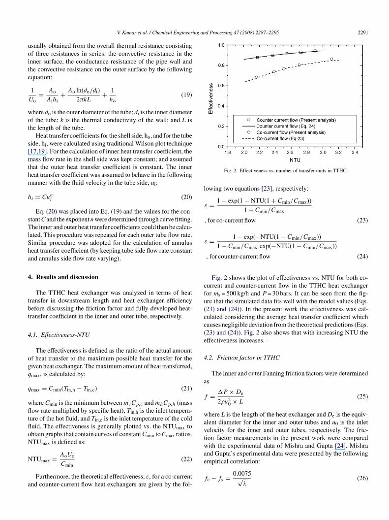
Fig. 2. Effectiveness vs. number of transfer units in TTHC.
owing two equations [23], respectively:
ε = 1 − exp(1 − NTU(1 + Cmin/Cmax))
1 + Cmin/Cmax
, for co-current flow (23)
ε = 1 − exp(−NTU(1 − Cmin/Cmax))
1 − Cmin/Cmax exp(−NTU(1 − Cmin/Cmax))
, for counter-current flow (24)
Fig. 2 shows the plot of effectiveness vs. NTU for both co-urrent and counter-current flow in the TTHC heat exchangeror ms = 500 kg/h and P = 30 bars. It can be seen from the fig-re that the simulated data fits well with the model values (Eqs.23) and (24)). In the present work the effectiveness was cal-ulated considering the average heat transfer coefficient whichauses negligible deviation from the theoretical predictions (Eqs.23) and (24)). Fig. 2 also shows that with increasing NTU theffectiveness increases.
.2. Friction factor in TTHC
The inner and outer Fanning friction factors were determineds
= P × De
2ρu20 × L
(25)
here L is the length of the heat exchanger and De is the equiv-lent diameter for the inner and outer tubes and u0 is the inletelocity for the inner and outer tubes, respectively. The fric-ion factor measurements in the present work were comparedith the experimental data of Mishra and Gupta [24]. Mishra
nd Gupta’s experimental data were presented by the following
mpirical correlation:c − fs = 0.0075√λ
(26)

2292 V. Kumar et al. / Chemical Engineering an
fw
f
4
ttfpdtw
4
as
[ttcowowpi
pifwFtT
4
wlcbwaict
Fig. 3. Friction factor vs. inner Reynolds number in TTHC.
or 4500 < NRe < 105, 6.7 < � < 346 and 0 < (H/2Rc) < 25.4,here fs is the friction factor in straight tube
s = 0.079
N0.25Re
(27)
.2.1. Inner friction factorFig. 3 shows the numerical predictions in the inner tube of
he TTHC at various inner tube flow rates. It can be seen fromhe figure that as the inner tube Reynolds number increases theriction factor decreases. Fig. 3 also illustrates the comparison ofresent predictions of the friction factor with the experimentalata reported by Mishra and Gupta [24]. It can be observed thathe numerical results in the inner tube of TTHC agree fairly wellith the experimental measurements of Mishra and Gupta [24].
.2.2. Outer friction factorThe numerical predictions of friction factor in the outer tube
re shown in Fig. 4. The fanning friction factor in the annuluside is compared with the data reported by Mishra and Gupta
Fig. 4. Friction factor vs. outer Reynolds number in TTHC.
iafRscrtatchtfiFoffltcd
w
d Processing 47 (2008) 2287–2295
24] for helically coiled tubes. It can be seen from the figure thathe pressure drop in the annulus section is higher as comparedo the data of Mishra and Gupta [24] for the similar processonditions. This may be due to friction generated by outer wallf the inner-coiled tube, inner wall of the outer-coiled tube asell as semicircular plate installed in the annulus region. Basedn the outer tube pressure drop data a new model is proposedhich accounts the curvature ratio and can also be used to predictressure drop in straight tube when λ = 0. The proposed models given below:
fc
fs= 1 + 0.0927N0.551
De , for 300 < NDe < 900 (28)
The accuracy of the proposed model was within ±2%. Theroposed model for outer friction factor is based on the numer-cal computations carried out without baffles in the TTHC. Theriction factor in inner and outer tubes were also comparedith the friction factor in straight tubes and also reported inigs. 3 and 4. It can be seen from both the figures that the fric-
ion factor is higher in both inner as well as outer tubes of theTHC heat exchanger as compared to the straight tube.
.3. Fully developed heat transfer
The fully developed heat transfer predictions in the presentork were compared with the experimental data reported in the
iterature for straight and curved tubes. During the numericalomputations the energy balances of inner and outer tubes haveeen calculated and it was observed that the energy balance wasell within 5% for all the computations. Fig. 5 shows the over-
ll heat transfer coefficient (Uo) for different values of flow raten the inner-coiled tube and in the annulus region for both co-urrent and counter-current flow systems. It can be seen fromhe figure that the overall heat transfer coefficient increases withncrease in the inner tube flow rate for a constant flow rate in thennulus region. About 30% increase in the overall heat trans-er coefficient was observed over two-fold change in the innereynolds number for both co-current and counter-current flow
ystems. Similar trends in the variation of overall heat transferoefficient were observed for different flow rates in the annulusegion. It can also be concluded from Fig. 5 that the overall heatransfer coefficient increases with increase in the flow rate in thennulus region for a constant inner tube flow rate. As expectedhe results from the counter-current flow were similar to the co-urrent flow configuration (changing the flow direction shouldave negligible effect on the heat transfer coefficients). Heatransfer rates, however, are much higher in the counterflow con-guration, due the increased log mean temperature difference.urther it can be seen from the figure that with the increasef operating pressure in the inner tube the overall heat trans-er coefficient increases. This may be due to the change in theuid properties when the operating pressure increases (during
he computations the properties of the compressed air were cal-
ulated at the corresponding inlet temperature and pressure, e.g.,ensity, viscosity, thermal conductivity and specific heat).The fully developed heat transfer predictions were comparedith the measurements of Mori and Nakayama [25] for inner
ing and Processing 47 (2008) 2287–2295 2293
a[
N
N
FQ
V. Kumar et al. / Chemical Engineer
nd outer tubes. The model proposed by Mori and Nakayama25] is as follows:
Mori and Nakayama [25]:
Nu,C = NPr
26.2(N2/3Pr − 0.074)
N4/5Re
(dt
dc
)1/10
×(
1 + 0.098
(NRe(dt/dc)2)1/5
)for NPr ≈ 1
and NRe(dt/dc)2 > 0.1. (29a)
Nu,CN−0.4Pr = 1
41.0N
5/6Re
(dt
dc
)1/12
×[
1 + 0.0611/6
]for NPr < 1
{NRe(dt/dc)2.5}and NRe(dt/dc)2.5 > 0.4. (29b)
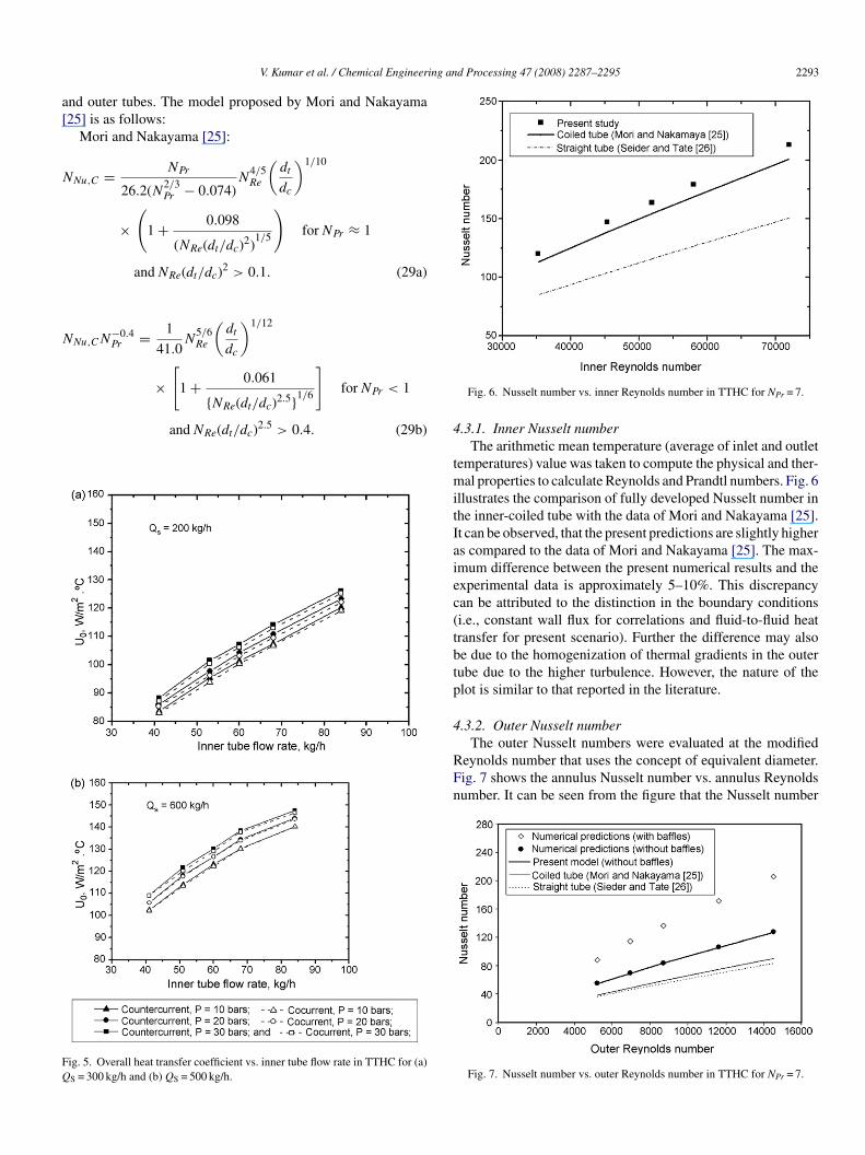
ig. 5. Overall heat transfer coefficient vs. inner tube flow rate in TTHC for (a)
S = 300 kg/h and (b) QS = 500 kg/h.
4
tmitIaiec(tbtp
4
RFn
Fig. 6. Nusselt number vs. inner Reynolds number in TTHC for NPr = 7.
.3.1. Inner Nusselt numberThe arithmetic mean temperature (average of inlet and outlet
emperatures) value was taken to compute the physical and ther-al properties to calculate Reynolds and Prandtl numbers. Fig. 6
llustrates the comparison of fully developed Nusselt number inhe inner-coiled tube with the data of Mori and Nakayama [25].t can be observed, that the present predictions are slightly highers compared to the data of Mori and Nakayama [25]. The max-mum difference between the present numerical results and thexperimental data is approximately 5–10%. This discrepancyan be attributed to the distinction in the boundary conditionsi.e., constant wall flux for correlations and fluid-to-fluid heatransfer for present scenario). Further the difference may alsoe due to the homogenization of thermal gradients in the outerube due to the higher turbulence. However, the nature of thelot is similar to that reported in the literature.
.3.2. Outer Nusselt number
The outer Nusselt numbers were evaluated at the modifiedeynolds number that uses the concept of equivalent diameter.ig. 7 shows the annulus Nusselt number vs. annulus Reynoldsumber. It can be seen from the figure that the Nusselt number
Fig. 7. Nusselt number vs. outer Reynolds number in TTHC for NPr = 7.

2294 V. Kumar et al. / Chemical Engineering an
Ff
vT(vcnNimrNpTthtt
dc
N
f
nmtprflta
5
e
itlcswt(attataIsiifiwwNt
A
aAACCdDhHkLnpP
qqRuuUT
ig. 8. Predicted vs. simulated Nusselt number in the outer tube of the TTHCor different Reynolds and Prandtl numbers.
alues increase with increase in the annulus Reynolds number.his is due to increase in turbulence between the fluid elements
semicircular baffles were placed in the outer tube which pro-ides turbulence to the annulus fluid). Fig. 7 also illustrates theomparison of present predictions of fully developed Nusseltumber in the outer tube with the experimental data of Mori andakayama [25]. The outer Nusselt number in the present work
s 2–3 times higher as compared to the Mori and Nakayama’seasurement. This may be due to the application of physically
ealistic boundary condition in the heat exchanger (Mori andakayama [25] used the constant wall temperature while in theresent work a direct fluid to fluid heat transfer was considered).he present experimental prediction for the fully developed heat
ransfer for inner and outer tubes were also compared with theeat transfer in straight tube and it was observed that the heatransfer in the present heat exchanger is higher as compared tohe straight tubes (Figs. 6 and 7).
For the outer tube heat transfer a new empirical model waseveloped from the numerical data considering all the processonditions used during the computations
Nu = 0.0509N0.817Re N0.3
Pr λ−0.1,
or 5000 < NRe < 15, 000 and 0.74 < NPr < 150 (30)
The maximum deviation between the model results and theumerical predictions was approximately ±3%. The proposedodel for outer heat transfer is based on the numerical computa-
ions carried out without baffles in the TTHC. The heat transferredictions from present numerical simulations and Eq. (30) areeported in Fig. 8 for both counter-current vs. the co-currentow configurations for Reynolds number varying from 5000
o 15,000 and Prandtl number 0.74–150. There is a reasonablegreement between the two values.
. Conclusions
Numerical study of a tube-in-tube helical coiled heatxchanger was performed considering compressed air in the
xx
d Processing 47 (2008) 2287–2295
nner tube at various operating pressures and cooling water inhe outer tube. The mass flow rate in the inner tube and the annu-us were both varied and the counter-current and co-current flowonfigurations were tested. The present numerical model con-iders physically realistic situations, such as heat conductionithin the tube walls, which was not considered in the litera-
ure. The numerically obtained overall heat transfer coefficientUo) for different values of flow rate in the inner-coiled tubend in the annulus region were reported. It was observed thathe overall heat transfer coefficient increases with increase inhe inner-coiled tube flow rate for a constant flow rate in thennulus region. Similar trends in the variation of overall heatransfer coefficient were observed for different flow rates in thennulus region for a constant flow rate in the inner-coiled tube.t was also observed that with the increase in operating pres-ure in the inner tube the overall heat transfer coefficient alsoncreases. The friction factor value in the inner-coiled tube wasn agreement with the literature data. The annulus side frictionactor values were higher as compared to the values reportedn the literature. The heat transfer in the inner and outer tubesas higher as compared to the data reported in the literature,hich may be due to the distinction in the boundary conditions.ew correlations have been proposed for pressure drop and heat
ransfer predictions in the outer tube of TTHC.
ppendix A. Nomenclature
radius of the helical pipe (m)area (m2)
T Van Driest constantconstant in Eq. (20)
p specific heat (kJ/kg K)tube diameter (m)coil diameter (m)heat transfer coefficient (W/m2 K)pitch (m)thermal conductivity (W/m K)length of heat exchanger (m)exponent in Eq. (20)pressure (N/m2)parameter to calculate the generation of turbulentkinetic energy due to the mean velocity gradient andbuoyancyheat transfer rate (J/s)
w wall heat flux (W/m2)c radius of the coil (m)i velocity component in i-direction (i = 1, 2, 3) (m/s)0 inlet velocity (m/s)
overall heat transfer coefficient (W/m2 K)temperature (K)
T1 temperature difference at inlet (K)
T2 temperature difference at outlet (K)spatial position (m)i master Cartesian coordinate in i-direction (i = 1, 2, 3)
(m)
ing an
Gα
ε
ϕ
kλ
ρ
μ
σ
σ
σ
τ
S0biow+
DNNNNN
R
[
[
[
[
[
[
[
[
[
[
[
[
[
[
[fluids, Ind. Eng. Chem. Des. Dev. 18 (1979) 130–137.
V. Kumar et al. / Chemical Engineer
reek lettersangle (◦)turbulent energy dissipationaxial angleturbulent kinetic energycurvature ratio (d/Dc)density of fluid (kg/m3)dynamic viscosity (kg/ms)
τ turbulent Prandtl number in energy equationk diffusion Prandtl number for kε turbulent Prandtl number for ε
w wall shear stress (N/m2)
ubscriptsinlet conditionsbulk quantityinside/inneroutside/outerwall conditionstandard wall coordinates.
imensionless numbersRe Reynolds number (=ρU0dh/μ)De Dean number (=NRe/
√λ)
Pr Prandtl number (=Cp × λ/k)Pr,w Turbulent wall Prandtl numberNu Nusselt number (=h × d/k)
eferences
[1] S.A. Berger, L. Talbot, L.S. Yao, Flow in curved pipes, Ann. Rev. FluidMech. 15 (1983) 461–512.
[2] R.K. Shah, S.D. Joshi, Convective heat transfer in curved ducts, in: S.Kakac, R.K. Shah, W. Aung (Eds.), Handbook of Single-Phase ConvectiveHeat Transfer, Wiley, New York, 1987 (Chapter 5).
[3] P. Naphon, S. Wongwises, A review of flow and heat transfer characteristicsin curved tubes, Renewable Sustainable Energy Rev. 10 (2006) 463–490.
[4] W.R. Dean, Note on the motion of fluid in a curved pipe, Philos. Mag. 4(1927) 208–223.
[5] W.R. Dean, The streamline motion of fluid in a curved pipe (second paper),Philos. Mag. 7 (1928) 673–695.
[6] A.R. Figueiredo, A.M. Raimundo, Analysis of the performances of heatexchangers used in Hot-water stores, Appl. Thermal Eng. 16 (1996)605–611.
[
[
d Processing 47 (2008) 2287–2295 2295
[7] S. Haraburda, Consider helical-coil heat exchangers, Chem. Eng. 102(1995) 149–151.
[8] B.V.S.S.S. Prasad, D.H. Das, A.K. Prabhakar, Pressure drop, heat transferand performance of a helically coiled tubular exchanger, Heat RecoverySyst. CHP 9 (1989) 249–256.
[9] R.K. Patil, B.W. Shende, P.K. Ghosh, Designing a helical-coil heatexchanger, Chem. Eng. 92 (1982) 85–88.
10] G.T. Karahalios, Mixed convection flow in a heated curved pipe with core,Phys. Fluids A 2 (1990) 2164–2175.
11] M.A. Petrakis, G.T. Karahalios, Technical note: steady flow in a curvedpipe with a coaxial core, Int. J. Num. Methods Fluids 22 (1996)1231–1237.
12] M.A. Petrakis, G.T. Karahalios, Exponential-decaying flow in agently curved annular pipe, Int. J. Non-Linear Mech. 32 (1997)823–835.
13] M.A. Petrakis, G.T. Karahalios, Fluid flow behavior in a curved annularconduit, Int. J. Non-Linear Mech. 34 (1999) 13–35.
14] K. Nandakumar, J.H. Masliyah, Swirling flow and heat transfer in coiledand twisted pipes, Advances in Transport Process, in: A.S. Mujumdar, R.AMasliyah (Eds.), vol. 4, Wiley Eastern.
15] S. Garimella, D.E. Richart, R.N. Christensen, Experimental investigationof heat transfer in coiled annular ducts, ASME J. Heat Transfer 110 (1988)329–336.
16] R.C. Xin, M.A. Ebadian, The effects of Prandtl numbers on local and aver-age convective heat transfer characteristic in helical pipes, J. Heat Transfer119 (1997) 467–473.
17] T.J. Rennie, V.G.S. Raghavan, Experimental studies of a double-pipe helical heat exchanger, Exp. Thermal Fluid Sci. 29 (2005)919–924.
18] T.J. Rennie, V.G.S. Raghavan, Numerical studies of a double-pipe helicalheat exchanger, Appl. Thermal Eng. 26 (2006) 1266–1273.
19] V. Kumar, S. Saini, M. Sharma, K.D.P. Nigam, Pressure drop and heattransfer study in tube-in-tube helical heat exchanger, Chem. Eng. Sci. 61(2006) 4403–4416.
20] V. Yakhot, S.A. Orszag, Renormalization group analysis of turbulence. I.Basic theory, J. Sci. Comp. 1 (1986) 1–51.
21] S.V. Patankar, Numerical Heat Transfer and Fluid Flow, Hemisphere, Wash-ington, DC, 1980.
22] J.P. Van Doormaal, G.D. Raithby, Enhancements of the SIMPLE method forpredicting incompressible flow problems, Numer. Heat Transfer 7 (1984)147–158.
23] F.M. White, Heat Transfer, Addison-Wesley Publishing Company, Inc.,Reading, Massachusetts, 1984, 588 pp.
24] P. Mishra, S.N. Gupta, Momentum transfer in curved pipes: Newtonian
25] Y. Mori, W. Nakiyama, Study on forced convective heat transfer in curvedpipes: Part – III, Int. J. Heat Mass Transfer 10 (1967) 681–695.
26] E.N. Sieder, G.E. Tate, Heat transfer and pressure drop of liquids in tubes,Ind. Eng. Chem. 28 (1936) 1429–1435.