NUCLEAR REACTOR MULTI-PHYSICS SIMULATIONS WITH ...
15
International Conference on Mathematics and Computational Methods Applied to Nuclear Science and Engineering (M&C 2011) Rio de Janeiro, RJ, Brazil, May 8-12, 2011, on CD-ROM, Latin American Section (LAS) / American Nuclear Society (ANS) ISBN 978-85-63688-00-2 2011 International Conference on Mathematics and Computational Methods Applied to Nuclear Science and Engineering (M&C 2011), Rio de Janeiro, RJ, Brazil, 2011 1/15 NUCLEAR REACTOR MULTI-PHYSICS SIMULATIONS WITH COUPLED MCNP5 AND STAR-CCM+ Jeffrey Neil Cardoni and Rizwan-uddin Department of Nuclear, Plasma, and Radiological Engineering University of Illinois at Urbana-Champaign, 104 S. Wright Street, Urbana, IL [email protected]; [email protected] ABSTRACT The MCNP5 Monte Carlo particle transport code has been coupled to the computational fluid dynamics code, STAR-CCM+, to provide a high fidelity multi-physics simulation tool for pressurized water nuclear reactors. The codes are executed separately and coupled externally through a Perl script. The Perl script automates the exchange of temperature, density, and volumetric heating information between the codes using ASCII text data files. Fortran90 and Java utility programs assist job automation with data post-processing and file management. The MCNP5 utility code, MAKXSF, pre-generates temperature dependent cross section libraries for the thermal feedback calculations. The MCNP5–STAR-CCM+ coupled simulation tool, dubbed MULTINUKE, was applied to a steady state, PWR cell model to demonstrate its usage and capabilities. The demonstration calculation showed reasonable results that agree with PWR values typically reported in literature. Temperature and fission reaction rate distributions were realistic and intuitive. Reactivity coefficients were also deemed reasonable in comparison to historically reported data. The demonstration problem consisted of 9,984 CFD cells and 7,489 neutronic cells. MCNP5 tallied fission energy deposition over 3,328 UO 2 cells. The coupled solution converged within eight hours and in three MULTINUKE iterations. The simulation was carried out on a 64 bit, quad core, Intel 2.8 GHz microprocessor with 1 GB RAM. The simulations on a quad core machine indicated that a massively parallelized implementation of MULTINUKE can be used to assess larger multi-million cell models. Key Words: Reactor multi-physics, Monte Carlo neutronics, CFD. 1. INTRODUCTION Consistent gains in microprocessor speed and memory size have made highly accurate and computationally expensive computer codes more practical in simulating complex system behavior. In the past, computation time limited high fidelity techniques to simplified models, and limited their use as audit tools for less accurate methods. With speed and memory size increasing approximately by a factor of two every eighteen months [1], modern nuclear reactor simulation practices have shifted to full three-dimensional models described by increasingly realistic physics codes. This includes the coupling of several different physics solvers into an integrated multi-physics analysis tool. The use of state of the art physics codes, combined into a coupled physics solver, represents the cutting edge of engineering and scientific simulations. The US Department of Energy’s Innovation Hub, Nuclear Energy Modeling and Simulation, specifically calls for the development of first-principles based multi-physics simulations for nuclear reactors [2]. High accuracy simulations, based on first-principles physics, can reduce
-
Upload
khangminh22 -
Category
Documents
-
view
0 -
download
0
Transcript of NUCLEAR REACTOR MULTI-PHYSICS SIMULATIONS WITH ...

International Conference on Mathematics and Computational Methods Applied to Nuclear Science and Engineering (M&C 2011)
Rio de Janeiro, RJ, Brazil, May 8-12, 2011, on CD-ROM, Latin American Section (LAS) / American Nuclear Society (ANS) ISBN 978-85-63688-00-2
2011 International Conference on Mathematics and Computational Methods Applied to
Nuclear Science and Engineering (M&C 2011), Rio de Janeiro, RJ, Brazil, 2011
1/15
NUCLEAR REACTOR MULTI-PHYSICS SIMULATIONS
WITH COUPLED MCNP5 AND STAR-CCM+
Jeffrey Neil Cardoni and Rizwan-uddin
Department of Nuclear, Plasma, and Radiological Engineering
University of Illinois at Urbana-Champaign, 104 S. Wright Street, Urbana, IL
[email protected]; [email protected]
ABSTRACT
The MCNP5 Monte Carlo particle transport code has been coupled to the computational fluid
dynamics code, STAR-CCM+, to provide a high fidelity multi-physics simulation tool for
pressurized water nuclear reactors. The codes are executed separately and coupled externally
through a Perl script. The Perl script automates the exchange of temperature, density, and
volumetric heating information between the codes using ASCII text data files. Fortran90 and Java
utility programs assist job automation with data post-processing and file management. The
MCNP5 utility code, MAKXSF, pre-generates temperature dependent cross section libraries for
the thermal feedback calculations.
The MCNP5–STAR-CCM+ coupled simulation tool, dubbed MULTINUKE, was applied to a
steady state, PWR cell model to demonstrate its usage and capabilities. The demonstration
calculation showed reasonable results that agree with PWR values typically reported in literature.
Temperature and fission reaction rate distributions were realistic and intuitive. Reactivity
coefficients were also deemed reasonable in comparison to historically reported data. The
demonstration problem consisted of 9,984 CFD cells and 7,489 neutronic cells. MCNP5 tallied
fission energy deposition over 3,328 UO2 cells. The coupled solution converged within eight
hours and in three MULTINUKE iterations. The simulation was carried out on a 64 bit, quad core,
Intel 2.8 GHz microprocessor with 1 GB RAM. The simulations on a quad core machine
indicated that a massively parallelized implementation of MULTINUKE can be used to assess
larger multi-million cell models.
Key Words: Reactor multi-physics, Monte Carlo neutronics, CFD.
1. INTRODUCTION
Consistent gains in microprocessor speed and memory size have made highly accurate and
computationally expensive computer codes more practical in simulating complex system
behavior. In the past, computation time limited high fidelity techniques to simplified models,
and limited their use as audit tools for less accurate methods. With speed and memory size
increasing approximately by a factor of two every eighteen months [1], modern nuclear reactor
simulation practices have shifted to full three-dimensional models described by increasingly
realistic physics codes. This includes the coupling of several different physics solvers into an
integrated multi-physics analysis tool. The use of state of the art physics codes, combined into a
coupled physics solver, represents the cutting edge of engineering and scientific simulations.
The US Department of Energy’s Innovation Hub, Nuclear Energy Modeling and Simulation,
specifically calls for the development of first-principles based multi-physics simulations for
nuclear reactors [2]. High accuracy simulations, based on first-principles physics, can reduce

Jeffrey N. Cardoni and Rizwan-uddin
2011 International Conference on Mathematics and Computational Methods Applied to
Nuclear Science and Engineering (M&C 2011), Rio de Janeiro, RJ, Brazil, 2011
2/15
design costs and uncertainty, thereby enhancing the economic feasibility and safety of nuclear
energy. Previous work related to the coupling of high-fidelity neutronic and thermal-hydraulic
codes for PWR simulations can be found in References [5, 9, and 10].
1.1. Background on Nuclear and Thermal-Hydraulic Feedback
There exist feedback effects amongst the nuclear, fluid, thermal, chemical, and structural
behavior of a nuclear reactor. The interplay between the neutronic and thermal-hydraulic
properties of a nuclear reactor core, called thermal or reactivity feedback, is a fundamental aspect
of nuclear core performance. The negative temperature reactivity coefficient – the negative
reactivity feedback from an increase in temperature – contributes to a nuclear reactor’s inherent
operational stability and safety. In pressurized water reactors, thermal feedback and temperature
coefficients of reactivity are primarily from microscopic cross section’s temperature dependence
and from the change in moderator density with temperature.
Microscopic cross section’s temperature dependence is a result of the Doppler effect. The
Doppler effect is a change in cross section due to temperature changes altering the thermal
motion of nuclei [3]. In general, an increase in temperature lowers and widens resonance peaks
to preserve the total area under the resonance. Although numerically smaller than the reactivity
coefficient due to moderator temperature change, the reactivity feedback effect from the Doppler
effect is almost instantaneous, making it a vital characteristic in nuclear reactor performance. In
a low enriched PWR, the Doppler effect decreases reactivity due to parasitic absorption in
epithermal U-238 resonances.
An increase in moderator temperature lowers the moderator density, altering the neutron
transport and energy spectrum characteristics of the core. Decreased moderator density reduces
the number of moderator atoms in a given region of the core, which in turn reduces scattering
and macroscopic absorption cross sections. Reduced total cross sections result in increased
neutron mean free path, increased leakage from the core, and decreased neutron thermalization.
Therefore, in a PWR, increased coolant/moderator temperature decreases reactivity, creating a
negative reactivity coefficient of greater magnitude than that of the Doppler effect [4].
1.2. Scope of the Research
The primary goal of this research was to incorporate state of the art, science-based neutronic and
thermal-hydraulic simulators into an integrated tool for coupled and automated reactor core
calculations. For this purpose, the Monte Carlo neutron transport code, MCNP5, is coupled to
the computational fluid dynamics code, STAR-CCM+, to simulate self-consistent thermal-
hydraulic and neutronic conditions in pressurized light-water reactors. The coupled solver,
called MULTINUKE, is used to calculate the converged steady state neutronic and thermal-
hydraulic properties of a single PWR cell model. MULTINUKE calculates and automatically
exchanges:
1. Fission heating in the fuel region, including prompt gamma heating in the fuel,
(calculated by MCNP5) for use as a volumetric (W/m3) heat source in STAR-CCM+.
2. Temperature distributions in the fuel, cladding, and coolant regions (calculated by
STAR-CCM+) for use in determining MCNP5 cross section libraries.

NUCLEAR REACTOR MULTI-PHYSICS SIMULATIONS
2011 International Conference on Mathematics and Computational Methods Applied to
Nuclear Science and Engineering (M&C 2011), Rio de Janeiro, RJ, Brazil, 2011
3/15
3. The density distribution in the coolant/moderator, calculated by STAR-CCM+, for use
in MCNP5 input files.
Temperature dependent cross section data libraries are pre-generated by the MCNP5 utility code,
MAKXSF. MAKXSF generates temperature dependent libraries by using Doppler-broadened
resolved resonance data, interpolating unresolved resonance probability tables, and interpolating
S(α,β) thermal scattering kernel data. For each reactor material, MAXKSF created several cross
section libraries binned by discrete temperature increments. Prior research on Monte Carlo and
CFD coupling, performed by Seker et al. [5], demonstrated sufficient accuracy in calculating
eigenvalues with MCNP5 using pre-generated cross section libraries binned by discrete
temperature increments.
There are no modifications made to the source codes of MCNP5 and STAR-CCM+; the codes
are executed separately and coupled through the Perl script. Therefore, the coupling scheme is
explicit, meaning several systems of equations are solved in an iterative fashion until the solution
appears converged. Data exchange is through ASCII data files, and automated by the
MULTINUKE Perl script. The term MULTINUKE refers to the solver processes involving
MCNP5 and STAR-CCM+, and the automation programs linking the two codes.
2. METHODS
Two fundamental quantities describing PWR core behavior are nuclear reaction rates and the
thermo-physical behavior of the water coolant and moderator. In a fission reactor, the neutron
population drives the most important nuclear reaction rates – including fission heating in the
fuel, and neutron heating in structures and water coolant. [Photon particle transport is important
for determining gamma heating, but will not be considered here. However, estimating gamma
heating in the fuel from prompt fission gamma rays does not require explicit photon particle
transport.] A first-principles approach to simulating reactor thermal-hydraulics necessitates
solving the mass, momentum, and energy transport equations for the working fluid, in
conjunction with modeling heat transfer from solid reactor materials to the coolant.
2.1. Neutronics
Neutron transport governs fundamental aspects of nuclear reactor performance. Neutron
interactions cause heating, nuclear fission, and induce radioactivity in reactor materials. These
interactions determine numerous essential core properties including reactor safety, reactivity
control, reactor kinetics, xenon stability, fuel depletion, and isotope production. Neutron
interactions play a central role in creating the power distributions that drive the heat transfer
process. There are strong feedback effects between nuclear physics and the other physical
processes in the reactor, particularly thermal-hydraulics.
Monte Carlo transport simulates neutron transport with computational particles, essentially
solving the neutron transport equation stochastically. With a sufficiently large sample of particle
histories, the central limit theorem can infer the average physical characteristics of particles in a
nuclear reactor within a confidence interval, including the neutron flux distribution [3]. This
numerical experiment is inherently realistic, especially when individual nuclear reactions are

Jeffrey N. Cardoni and Rizwan-uddin
2011 International Conference on Mathematics and Computational Methods Applied to
Nuclear Science and Engineering (M&C 2011), Rio de Janeiro, RJ, Brazil, 2011
4/15
based on first-principles physics, since particle transport is an intrinsically stochastic
phenomenon [4]. In contrast to deterministic transport, Monte Carlo methods generally allow for
exact geometry modeling and continuous treatments of neutron energy and direction. Monte
Carlo codes also have an advantage in the ease of developing massively parallel algorithms [6].
MCNP5 (Monte Carlo N-Particle Version 5) is used to calculate the fission reaction rate
distribution in the fuel region to create a heat source for thermal-hydraulic coupling. It also
calculates the eigenvalue of the model to assess the reactivity effects of fuel and moderator
temperature. In this work, a Linux MPI executable was compiled without any modification to
the Fortran90 source code obtained from RSICC (Radiation Safety Information Computational
Center at Oak Ridge National Laboratory). MCNP5 features accurate 3D geometry modeling
and the best available, continuous nuclear data and physics, along with S(α,β) thermal scattering
tables. Neutronic data is from the ENDF/B-VII.0, nuclear data cross sections evaluated in 2006.
To calculate fission heating in the fuel, the fission energy deposition tally (the F7:N tally) is used
in MCNP5. It computes cell fission heating in units of MeV/g. The F7:N tally includes gamma
heating in the fuel, because energy from prompt fission gammas are deposited locally [3]. The
F7:N tally is equivalent to a F4:N track length flux tally multiplied by an energy multiplier on
the FM card. The F7:N tally is a track length tally that calculates the quantity
�f = �a� � � � �� ��3� � ��σf()�(�, , �, ). (1)
In this expression, �f is the cell’s deposited fission energy (MeV/g), �a is the atom density
(atoms/barn-cm),� is the mass of the cell (g),� is the fission heating Q-value (MeV), and σf() is the microscopic fission cross section (barns). MCNP5 tallies for criticality problems are
normalized to be per fission neutron created [3].
2.2. Thermal-hydraulics
The other half of the coupled nuclear and thermal-hydraulic solver involves the calculation of the
temperature distribution in the core, and the density distribution of the coolant. Energy is
extracted from a reactor by transferring the heat generated by nuclear reactions to a working
fluid. Therefore, the thermal-hydraulic behavior of a PWR requires the solution of the heat
conduction equation in the fuel rod, and the solution to the fluid mass, momentum, and energy
transport equations. Computational fluid dynamics is a state of the art method for thermal-
hydraulics analysis. For reactor analysis, it entails discretizing and solving the governing
equations over the domain of the reactor. The geometric domain is approximated by a CFD
mesh using finite difference, finite element, or finite volume discretization methods. The CFD
code STAR-CCM+ [7] is used to calculate temperature and density distributions for PWR
simulations.
STAR-CCM+ models fluid flow and heat transfer, as well as heat transfer in solids, for complex
three-dimensional geometries. It solves the Navier-Stokes equations discretized using the finite-
volume approach for steady state and time-dependent problems. STAR-CCM+ can represent
solid, liquid, gaseous, and porous media. Heat may be transferred via conduction, radiation, and
convection. STAR-CCM+ models both single and multi-phase flow, with the ability to model
boiling and cavitation phase changes [7].
NUCLEAR REACTOR MULTI-PHYSICS SIMULATIONS
2011 International Conference on Mathematics and Computational Methods Applied to
Nuclear Science and Engineering (M&C 2011), Rio de Janeiro, RJ, Brazil, 2011
5/15
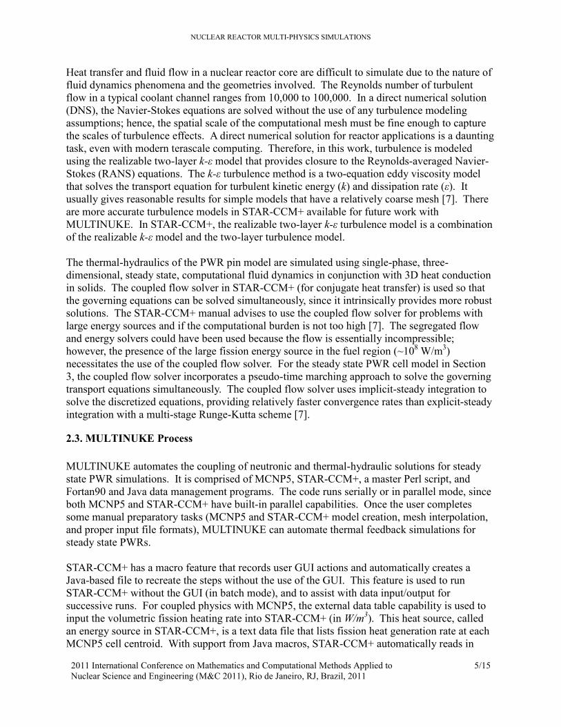
Heat transfer and fluid flow in a nuclear reactor core are difficult to simulate due to the nature of
fluid dynamics phenomena and the geometries involved. The Reynolds number of turbulent
flow in a typical coolant channel ranges from 10,000 to 100,000. In a direct numerical solution
(DNS), the Navier-Stokes equations are solved without the use of any turbulence modeling
assumptions; hence, the spatial scale of the computational mesh must be fine enough to capture
the scales of turbulence effects. A direct numerical solution for reactor applications is a daunting
task, even with modern terascale computing. Therefore, in this work, turbulence is modeled
using the realizable two-layer k-ε model that provides closure to the Reynolds-averaged Navier-
Stokes (RANS) equations. The k-ε turbulence method is a two-equation eddy viscosity model
that solves the transport equation for turbulent kinetic energy (k) and dissipation rate (ε). It
usually gives reasonable results for simple models that have a relatively coarse mesh [7]. There
are more accurate turbulence models in STAR-CCM+ available for future work with
MULTINUKE. In STAR-CCM+, the realizable two-layer k-ε turbulence model is a combination
of the realizable k-ε model and the two-layer turbulence model.
The thermal-hydraulics of the PWR pin model are simulated using single-phase, three-
dimensional, steady state, computational fluid dynamics in conjunction with 3D heat conduction
in solids. The coupled flow solver in STAR-CCM+ (for conjugate heat transfer) is used so that
the governing equations can be solved simultaneously, since it intrinsically provides more robust
solutions. The STAR-CCM+ manual advises to use the coupled flow solver for problems with
large energy sources and if the computational burden is not too high [7]. The segregated flow
and energy solvers could have been used because the flow is essentially incompressible;
however, the presence of the large fission energy source in the fuel region (~108 W/m
3)
necessitates the use of the coupled flow solver. For the steady state PWR cell model in Section
3, the coupled flow solver incorporates a pseudo-time marching approach to solve the governing
transport equations simultaneously. The coupled flow solver uses implicit-steady integration to
solve the discretized equations, providing relatively faster convergence rates than explicit-steady
integration with a multi-stage Runge-Kutta scheme [7].
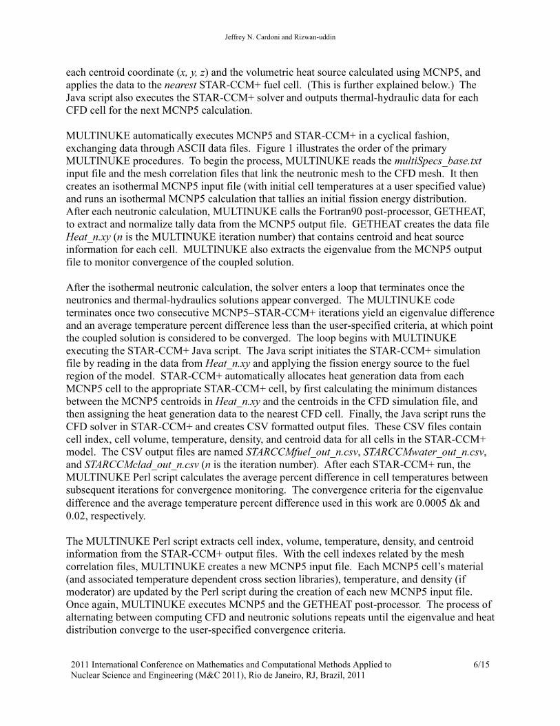
2.3. MULTINUKE Process
MULTINUKE automates the coupling of neutronic and thermal-hydraulic solutions for steady
state PWR simulations. It is comprised of MCNP5, STAR-CCM+, a master Perl script, and
Fortan90 and Java data management programs. The code runs serially or in parallel mode, since
both MCNP5 and STAR-CCM+ have built-in parallel capabilities. Once the user completes
some manual preparatory tasks (MCNP5 and STAR-CCM+ model creation, mesh interpolation,
and proper input file formats), MULTINUKE can automate thermal feedback simulations for
steady state PWRs.
STAR-CCM+ has a macro feature that records user GUI actions and automatically creates a
Java-based file to recreate the steps without the use of the GUI. This feature is used to run
STAR-CCM+ without the GUI (in batch mode), and to assist with data input/output for
successive runs. For coupled physics with MCNP5, the external data table capability is used to
input the volumetric fission heating rate into STAR-CCM+ (in W/m3). This heat source, called
an energy source in STAR-CCM+, is a text data file that lists fission heat generation rate at each
MCNP5 cell centroid. With support from Java macros, STAR-CCM+ automatically reads in
Jeffrey N. Cardoni and Rizwan-uddin
2011 International Conference on Mathematics and Computational Methods Applied to
Nuclear Science and Engineering (M&C 2011), Rio de Janeiro, RJ, Brazil, 2011
6/15
each centroid coordinate (x, y, z) and the volumetric heat source calculated using MCNP5, and
applies the data to the nearest STAR-CCM+ fuel cell. (This is further explained below.) The
Java script also executes the STAR-CCM+ solver and outputs thermal-hydraulic data for each
CFD cell for the next MCNP5 calculation.
MULTINUKE automatically executes MCNP5 and STAR-CCM+ in a cyclical fashion,
exchanging data through ASCII data files. Figure 1 illustrates the order of the primary
MULTINUKE procedures. To begin the process, MULTINUKE reads the multiSpecs_base.txt
input file and the mesh correlation files that link the neutronic mesh to the CFD mesh. It then
creates an isothermal MCNP5 input file (with initial cell temperatures at a user specified value)
and runs an isothermal MCNP5 calculation that tallies an initial fission energy distribution.
After each neutronic calculation, MULTINUKE calls the Fortran90 post-processor, GETHEAT,
to extract and normalize tally data from the MCNP5 output file. GETHEAT creates the data file
Heat_n.xy (n is the MULTINUKE iteration number) that contains centroid and heat source
information for each cell. MULTINUKE also extracts the eigenvalue from the MCNP5 output
file to monitor convergence of the coupled solution.
After the isothermal neutronic calculation, the solver enters a loop that terminates once the
neutronics and thermal-hydraulics solutions appear converged. The MULTINUKE code
terminates once two consecutive MCNP5–STAR-CCM+ iterations yield an eigenvalue difference
and an average temperature percent difference less than the user-specified criteria, at which point
the coupled solution is considered to be converged. The loop begins with MULTINUKE
executing the STAR-CCM+ Java script. The Java script initiates the STAR-CCM+ simulation
file by reading in the data from Heat_n.xy and applying the fission energy source to the fuel
region of the model. STAR-CCM+ automatically allocates heat generation data from each
MCNP5 cell to the appropriate STAR-CCM+ cell, by first calculating the minimum distances
between the MCNP5 centroids in Heat_n.xy and the centroids in the CFD simulation file, and
then assigning the heat generation data to the nearest CFD cell. Finally, the Java script runs the
CFD solver in STAR-CCM+ and creates CSV formatted output files. These CSV files contain
cell index, cell volume, temperature, density, and centroid data for all cells in the STAR-CCM+
model. The CSV output files are named STARCCMfuel_out_n.csv, STARCCMwater_out_n.csv,
and STARCCMclad_out_n.csv (n is the iteration number). After each STAR-CCM+ run, the
MULTINUKE Perl script calculates the average percent difference in cell temperatures between
subsequent iterations for convergence monitoring. The convergence criteria for the eigenvalue
difference and the average temperature percent difference used in this work are 0.0005 Δk and
0.02, respectively.
The MULTINUKE Perl script extracts cell index, volume, temperature, density, and centroid
information from the STAR-CCM+ output files. With the cell indexes related by the mesh
correlation files, MULTINUKE creates a new MCNP5 input file. Each MCNP5 cell’s material
(and associated temperature dependent cross section libraries), temperature, and density (if
moderator) are updated by the Perl script during the creation of each new MCNP5 input file.
Once again, MULTINUKE executes MCNP5 and the GETHEAT post-processor. The process of
alternating between computing CFD and neutronic solutions repeats until the eigenvalue and heat
distribution converge to the user-specified convergence criteria.

NUCLEAR REACTOR MULTI-PHYSICS SIMULATIONS
2011 International Conference on Mathematics and Computational Methods Applied to
Nuclear Science and Engineering (M&C 2011), Rio de Janeiro, RJ, Brazil, 2011
7/15
Files Created
MCNP5 isothermal input file
MCNP5 isothermal output file
Heat_0.xy
STARCCMfuel_out_n.csv
STARCCMwater_out_n.csv
STARCCMclad_out_n.csv
MCNP5 input file for iteration n
MCNP5 output file for iteration n
Heat_n.xy
convergenceSummary.txt
Figure 1. MULTINUKE solver processes.
Execution of MULTINUKE Perl script
Run GETHEAT: Fortran90 post-processor to
extract power distribution (W/m3) in a format
readable by STAR-CCM+. Create Heat_0.xy
file.
Run Java script that executes STAR-CCM+ and
reads in MCNP5 energy source (W/m3). Output
temperature and density data for fuel, clad, and
water regions in the form of CSV files. (Begin
convergence loop.)
Extract data from STAR-CCM+ CSV files and
apply the data to appropriate MCNP5 cells in a
new MCNP5 input file.
Run subsequent MCNP5 calculation and
GETHEAT post-processor.
Read multiSpecs_base.txt input and mesh
correlation files, create isothermal MCNP5 input
file, and execute MCNP5 isothermal job.
Check for neutronic and thermal-hydraulic
convergence: calculate eigenvalue and
temperature convergence parameters.
Loop until convergence criteria are satisfied, or until maximum iteration count is reached.
1
2
3
4
5
6
7

Jeffrey N. Cardoni and Rizwan-uddin
2011 International Conference on Mathematics and Computational Methods Applied to
Nuclear Science and Engineering (M&C 2011), Rio de Janeiro, RJ, Brazil, 2011
8/15
3. RESULTS: TEST CALCULATION
The MULTINUKE solver was applied to a single pin model to investigate the steady state,
coupled neutronics and thermal-hydraulics state of a PWR representative cell. The PWR cell
model was run on a 64 bit, quad core, Intel 2.8 GHz microprocessor with 1 GB RAM. A Linux
MPI executable was compiled from the MCNP5 source code for parallel neutronics. STAR-
CCM+ is released fully capable of parallel processing, and was executed in parallel mode on the
machine’s four cores.
3.1. PWR Cell Model
The PWR cell model consists of a cylindrical fuel rod (fuel, cladding) surrounded by coolant
contained within boundaries in the x and y directions. The PWR cell model simulates a PWR
core as an infinite array of identical fuel cells, because of symmetric boundary conditions
imposed on its radial surfaces. However, the model is finite in the axial direction, allowing axial
neutron leakage and coolant to flow in and out of the model. The purpose of the single PWR cell
model is twofold: to provide a fast running simulation for debugging MULTINUKE and to
calculate pseudo-realistic PWR properties. Although coupled, multi-physics reactor simulations
are intended to analyze large complex models with massively parallel computing, and
MULTINUKE is also envisioned for this purpose, the single cell model is first developed to
demonstrate the usage of MULTINUKE on a quad core machine. Therefore, the number of mesh
cells in the model is held to a minimum by reducing the height of the model to 20 cm. This
allows STAR-CCM+ to generate a simple prismatic hexahedral CFD mesh with 9,984
computational cells, which consequently facilitates the creation of an equivalent neutronic grid in
MCNP5 (excluding the clad region that is lumped into one MCNP5 cell). All axial nodes have
the same radial mesh structure.
Table I contains data for the PWR cell model, and subsequent mesh and simulation. The fuel
diameter is 1.0 cm, and the outer clad diameter is 1.2 cm, resulting in a 0.1 cm cladding
thickness with no fuel-clad gap modeled. The reactor lattice has a pitch of 1.5 cm and an axial
height of 20.0 cm. The nuclear fuel material is UO2 with 5 w/o U-235 enrichment. Cladding is
made of Zircaloy-4 and liquid water is the coolant and neutron moderator.
Table I. PWR Cell Model Data.
Lattice Data Value
Fuel Outer Diameter (cm) 1.0
Fuel Cladding Outer Diameter (cm) 1.2
Fuel Cladding Thickness (cm) 0.1
Fuel Rod Pitch (cm) 1.5
Axial Height (cm) 20.0
Fuel Material UO2
Fissile Material Enrichment 5 w/o U-235
Cladding Material Zircaloy-4
Coolant/Moderator Material Liquid H2O
Mesh Data Value
Mesh Type Prismatic Hexahedral

NUCLEAR REACTOR MULTI-PHYSICS SIMULATIONS
2011 International Conference on Mathematics and Computational Methods Applied to
Nuclear Science and Engineering (M&C 2011), Rio de Janeiro, RJ, Brazil, 2011
9/15
Total STAR-CCM+ Cells 9,984
Number of Radial STAR-CCM+ Cells per Axial Node 96
Number of STAR-CCM+ Axial Nodes 104
Total MCNP5 Cells 7488 + 1 Clad Cell
Number of Radial MCNP5 Cells per Axial Node 72
Number of MCNP5 Axial Nodes 104
Number of MCNP5 Tally Regions (UO2 Cells) 3328
STAR-CCM+ automatically generates the volumetric computational mesh. An axially uniform
mesh is desired to facilitate coupling with the neutronics mesh; thus a prismatic hexahedral CFD
mesh is generated using the “trimmer” mesh model in STAR-CCM+. The model has 96 radial
CFD cells per axial node, with 104 axial nodes, resulting in 9,984 CFD computational cells. An
equivalent neutronic grid is created in MCNP5 with help from a simple Fortran90 program. The
MCNP5 computational cells have almost identical centroids and volumes compared to the
STAR-CCM+ cells, except for the clad region that is reduced to one cell in the MCNP5 input
file. The cladding temperature for MCNP5 is calculated as the volume weighted average of the
STAR-CCM+ clad cells’ temperatures. The neutron cross section of Zircaloy is small, making
the clad region relatively transparent compared to the fuel and moderator regions. Therefore, the
detailed temperature distribution in the clad region can be neglected without significantly
influencing the neutron transport and power distribution calculated by MCNP5. The MCNP5
model for the pin has 7489 computational cells including 3328 tallied fuel cells. Figure 2 depicts
the MCNP5 mesh and STAR-CCM+ mesh for the PWR model. The upper-right quadrant of the
coolant mesh is numbered for the results presented in Section 3.2 (see Fig. 7).
Figure 2. MCNP5 mesh (left) and STAR-CCM+ mesh (right) for PWR cell simulation.
Table I (continued)
1 2 3 4
5 6 7
8 9
10 Fuel
Clad
Coolant

Jeffrey N. Cardoni and Rizwan-uddin
2011 International Conference on Mathematics and Computational Methods Applied to
Nuclear Science and Engineering (M&C 2011), Rio de Janeiro, RJ, Brazil, 2011
10/15
The PWR cell model has a constant (1 m/s) velocity inlet, and a constant pressure outlet. The
thermo-physical properties of the solid UO2 and Zircaloy-4 regions are assumed to be constant.
The water coolant also has constant thermal conductivity, dynamic viscosity, and turbulent
Prandtl number. The density and specific heat capacity of the coolant in STAR-CCM+ are not
constant, but rather polynomial functions of the cell temperature.
To model the equation of state, STAR-CCM+ simulates the thermal expansion of coolant in the
PWR cell model using a user-specified polynomial fluid density. When simulating a single-
phase fluid with the steady-state coupled flow solver, STAR-CCM+ allows for constant density,
density varying as a polynomial, and ideal gas treatment for the equation of state. The most
appropriate equation of state for the PWR cell model is the polynomial density treatment.
Making use of water density data from Ref. [8], the equation for coolant density as a function of
temperature at 2000 psi pressure is:
�(�) = � 1006, ��� < 277.6−4.12x10#$�% + 6.74x10#'�( − 4.31x10#*�* + 11.8� − 154, ��277.6 ≤ � ≤ 600657.4, ��� > 600. (2)
In this equation for H2O density (kg/m3), temperature (T) is in Kelvin and coolant density is
assumed to be constant beyond the temperature range of interest for the PWR model. Figure 3
shows the variation of coolant density with temperature. The red curve represents the density
equation for H2O (Eq. (2)) and the blue dots are the data for water density from Ref. [8].
Figure 3. Water density temperature dependence in PWR cell simulation.
3.2. Results
The MULTINUKE simulation of the PWR cell model took approximately 8 hours to converge.
The coupled solution took only three MULTINUKE iterations due to the symmetry of the simple
cell model. The eigenvalue of the converged pin simulation is 0.6601 ± 0.0009 (95% confidence
interval). The nuclear Doppler reactivity coefficient is roughly -2.5 pcm/K. The moderator
temperature coefficient ranges from approximately -36.0 pcm/K to -12.4 pcm/K.
600
650
700
750
800
850
900
950
1000
1050
250 300 350 400 450 500 550 600 650
Density (kg/m
3)
Temperature (K)

NUCLEAR REACTOR MULTI-PHYSICS SIMULATIONS
2011 International Conference on Mathematics and Computational Methods Applied to
Nuclear Science and Engineering (M&C 2011), Rio de Janeiro, RJ, Brazil, 2011
11/15
Figure 4 shows the converged relative axial power distribution for the PWR pin model, along
with the 3D fuel temperature distribution (the color bar does not reflect the entire range of data,
but only the range of data on the exterior surfaces visible in the geometry scene). The data for
the relative axial power distribution in Figure 4 is from an F4:N (cell track length) MCNP5 tally
modified to calculate the fission reaction rate in each fuel cell. In the GETHEAT post-processor,
the fission reaction rates are radially integrated at each axial node to determine the total fission
rate for each axial node. The average nodal-fission rate is also computed. The axial power
peaking factor, normalized to the nodal average, is then calculated for each axial level. The
relative power distribution for the pin model remained unchanged after two successive iterations.
Figure 4. Axial power profile and 3D fuel temperature distribution for PWR cell
model.
As expected, the axial power distribution is essentially sinusoidal, owing to the fact that the
model lacks axial reflectors, axial variations in fuel enrichment, or control rods. The average cell
power density is 3.86x10⁸ W/m
3, and the maximum cell power density is 9.43x10
8 W/m
3 (taking
into account axial and radial peaking). Figure 5 shows the power density in every cell in the fuel
plotted against the z-axis for different radial locations. As expected, fuel cells near the edge of
the pin are exposed to greater thermal neutron flux compared to cells near the center, due to self-
shielding. The outer fuel cells therefore have greater fission reaction rates and higher power
densities, as shown in Figure 5. When each cell’s power density is multiplied by its volume and
added together, the input power for the cell model (4700 W) is obtained.
0
2
4
6
8
10
12
14
16
18
20
0 0.2 0.4 0.6 0.8 1 1.2 1.4 1.6
Axial Height (cm)
Relative Axial Power Peaking Factor Inlet
Exit

Jeffrey N. Cardoni and Rizwan-uddin
2011 International Conference on Mathematics and Computational Methods Applied to
Nuclear Science and Engineering (M&C 2011), Rio de Janeiro, RJ, Brazil, 2011
12/15
Figure 5. Axial power density distributions for different radial distances from fuel
centerline.
Figure 6 is a plot of the converged temperatures for computational cells in the fuel as a function
of axial location. The fuel cells closest to the center of the pin (r ≈ 0.14 cm) have the highest
temperatures; the maximum fuel temperature is 1464.9 K at z = 10.3 cm for the PWR cell model.
r ≈ 0.14 cm to 0.31 cm
r ≈ 0.40 cm r ≈ 0.44 cm
r ≈ 0.47 cm

NUCLEAR REACTOR MULTI-PHYSICS SIMULATIONS
2011 International Conference on Mathematics and Computational Methods Applied to
Nuclear Science and Engineering (M&C 2011), Rio de Janeiro, RJ, Brazil, 2011
13/15
Figure 6. Axial fuel temperature distributions for different radial locations.
Figure 7 shows the axial variation of the coolant temperature. The plot shows the axial variation
of temperature for coolant cells in one quadrant of the model (cell numbers 1-10). As can be
seen, coolant temperature increases monotonically in some cells, while at others it drops near the
exit. The temperature drops near the exit in the radial locations (cells 5, 8) where the
temperature rise was the fastest. The slight temperature drop near the exit is most likely a result
of the shortened axial length of the model and flow mixing. Also shown in Figure 7 is a contour
plot of radial velocity for coolants cells 1-10 at the top axial node of the model (the exit). It
shows that the coolant velocity field has a nonzero radial component, providing evidence of
some flow mixing; at this particular axial node, most of the cells have an inward (less than zero)
radial velocity. Other axial nodes have cells with nonzero radial velocities that vary in direction
(outward/inward) and magnitude. The highest radial velocity is only about 0.02 m/s, or about
2% of the inlet velocity, and this suggests some flow mixing may be the cause of the slight (1 K)
temperature decrease near the exit for cells 5 and 8.
r ≈ 0.47 cm
r ≈ 0.44 cm
r ≈ 0.40 cm
r ≈ 0.31 cm
r ≈ 0.14 cm

Jeffrey N. Cardoni and Rizwan-uddin
2011 International Conference on Mathematics and Computational Methods Applied to
Nuclear Science and Engineering (M&C 2011), Rio de Janeiro, RJ, Brazil, 2011
14/15
The maximum coolant temperature is 587.9 K, occurring at 16.3 cm from the inlet. The average
exit coolant temperature is 581 K, suggesting an average temperature rise of about 11 K for the
coolant (Texit – Tinlet). The inlet temperature was set to 570 K for the simulation. The coolant
density ranges from 687.8 kg/m3 to 727.9 kg/m
3. The average coolant density is 716 kg/m
3,
corresponding to the average coolant temperature of 575.8 K.
Figure 7. Axial coolant temperature distributions and contour plot of radial velocity in
coolant cells 1-10.
4. Summary
The MCNP5 Monte Carlo particle transport code has been coupled to the computational fluid
dynamics code, STAR-CCM+, to provide a high fidelity multi-physics simulation tool for
pressurized water nuclear reactors. The codes are executed separately and coupled externally
through a Perl script that automates the exchange of temperature, density, and volumetric heating
information between the codes using ASCII text data files.
The PWR cell test case provided verification of the methodology used to couple the neutronic
and CFD codes. The MCNP5 cell model provided evidence of converged eigenvalue and fission
source distribution. Furthermore, the MCNP5 model had adequate tally statistics and intuitively
expected reactivity coefficients. The STAR-CCM+ cell model had appropriate residuals
convergence for the CFD simulations. Finally, the coupled MULTINUKE simulation
0
2
4
6
8
10
12
14
16
18
20
568 570 572 574 576 578 580 582 584 586 588
Axial Height (cm)
Temperature (K)
Cell 4 Cells 3,7 Cells 2,9 Cell 6
Cells 1,10
Cells 5,8
1 2 3 4
5 6 7
8 9
10
Fuel

NUCLEAR REACTOR MULTI-PHYSICS SIMULATIONS
2011 International Conference on Mathematics and Computational Methods Applied to
Nuclear Science and Engineering (M&C 2011), Rio de Janeiro, RJ, Brazil, 2011
15/15
demonstrated realistic and intuitive power distributions, temperature distributions, coolant
densities, and fluid flow characteristics for a simple PWR model.
The next logical step for further work would be to apply MULTINUKE to a PWR fuel assembly
model of realistic height (3 to 4 meters). The PWR assembly model could range in size from a
simple 3 x 3 lattice, up to a full 17 x 17 PWR fuel assembly, depending on available
computational resources and the resolution of the computational grid. Preliminary analysis of a
simple 3 x 3 PWR model (4 meters tall) has already been performed, where the computational
mesh consists of 89,856 cells and is based on the mesh used for the PWR cell model.
Beyond PWR assembly models, it is hoped that MULTINUKE may eventually be used for more
advanced applications. Specifically, further development of MULTINUKE would include its
implementation on massively parallel supercomputers. The simple test problem solved in this
work took eight hours on four cores of a quad-processor machine. Massively parallel computing
with MULTINUKE could analyze large nuclear reactor models with more complicated
neutronic–thermal-hydraulic feedback effects, such as BWRs and fast reactors. Such advanced,
high fidelity, multi-physics reactor simulations can assist in furthering the state-of-the-art
through innovative validation of reactor safety and economic viability.
REFERENCES
1. F. B. Brown, J. T. Goorley, and J. E. Sweezy, "MCNP5 Parallel Processing Workshop,"
Proceedings of ANS Mathematics & Computation Topical Meeting, Gatlinburg, Tennessee,
April 11 (2003).
2. “Modeling & Simulation for Nuclear Reactors,”
http://www.energy.gov/hubs/modeling_simulation_nuclear_reactors.htm, (2010).
3. X-5 Monte Carlo Team, “MCNP – A General Monte Carlo N-Particle Transport Code,
Version 5,” Los Alamos, New Mexico (2008).
4. W. M. Stacey, Nuclear Reactor Physics, Wiley-VCH, Weinheim, Germany (2007).
5. V. Seker, J. W. Thomas, and T. J. Downar, “Reactor Physics Simulations With Coupled
Monte Carlo Calculation and Computational Fluid Dynamics,” Proceedings of International
Conference on Emerging Nuclear Energy Systems, Istanbul, Turkey, June 3-8 (2007).
6. T. J. Downar, A. Siegel, and C. Unal, “Science Based Nuclear Energy Systems Enabled by
Advanced Modeling and Simulation at the Extreme Scale,” Workshop Summary, Crystal
City, Virginia, May 11-12 (2009).
7. CD-adapco, “User Guide: STAR-CCM+ Version 2.10.017,” CD-adapco (2007).
8. M. M. El-Wakil, Nuclear Heat Transport, The American Nuclear Society, La Grange Park,
Illinois (1993).
9. D. P. Weber, T. Sofu, T. H. Chun, H. G. Joo, J. W. Thomas, Z. Zhong, T. J. Downar,
“Development of Comprehensive Modeling Capability Based on Rigorous Treatment of
Multi-Physics Phenomena Influencing Reactor Core Design,” Proceedings of International
Congress on Advances in Nuclear Power Plants, Pittsburgh, Pennsylvania, June 13-17
(2004).
10. J. Hu and Rizwan-uddin, “Coupled Neutronics and Thermal-Hydraulics Using MCNP and
FLUENT,” Transactions of the American Nuclear Society, 98, pp. 606-608 (2008).