Physics - REB
352
for Rwanda Secondary Schools Learner’s Book Senior Two Physics fountain publishers www.fountainpublishers.co.ug Nzarora Ieonce Lenz
-
Upload
khangminh22 -
Category
Documents
-
view
0 -
download
0
Transcript of Physics - REB

for Rwanda Secondary Schools
Learner’s Book
Senior Two
Physics
fountain publisherswww.fountainpublishers.co.ug
Nzarora Ieonce Lenz

Fountain Publishers Rwanda LtdP.O. Box 6567Kigali, RwandaE-mail: [email protected] [email protected] [email protected] Website: www.fountainpublishers.co.ug
© Fountain Publishers 2017First published 2017
All rights reserved. No part of this publication may be reproduced, stored in a retrieval system, or transmitted in any form or by any means, electronic, mechanical, photocopying, recording or otherwise, without prior written permission from the publishers.
ISBN: 978-9970-19-398-1

iii
Contents
Introduction .............................................................................. vii
TOPIC: Mechanics ......................................................................... 1Sub-topic: Motion .......................................................................................1
Unit 1: Sources of Errors in Measurement of Physical Quantities ................31.1 Dimensions of physical quantities ............................................41.2 Sources of errors in measurement of physical quantities .............81.3 Estimating the uncertainty range of measurement ....................191.4 Significant figures of measurements .......................................211.5 Rounding off numbers ..........................................................241.6 Unit 1 assessment ..............................................................25
TOPIC: Mechanics ....................................................................... 27Sub-topic: Force .......................................................................................27
Unit 2: Quantitative Analysis of Linear Motion ........................................292.1 Definition and types of linear motion .....................................302.2 Equation for uniform acceleration and in one dimension ...........322.3 Acceleration due to gravity and free fall ..................................392.4 Determination of G: Use of a simple pendulum ........................452.5 Unit 2 assessment ...............................................................48
Sub-topic: Mechanics ...............................................................................51
Unit 3: Frictional Force ........................................................................533.1 Nature of frictional force ......................................................543.2 Types of frictional forces .......................................................553.3 The laws of solids friction ....................................................563.4 Effects of friction ..................................................................563.5 Advantages and disadvantages of friction ................................573.6 Factors affecting friction and how to reduce it ..........................573.7. Other resistance forces ........................................................583.8 Unit 3 assessment ...............................................................64
Sub-topic: Mechanics ...............................................................................67
Unit 4: Density and Pressure in Solids and Fluids ...................................694.1 Force exerted by solids .........................................................704.2 Definition and units of pressure .............................................724.3 Static fluid pressure ............................................................754.4 Atmospheric pressure ...........................................................76

iv
4.5 Gas pressure .......................................................................794.6 Simple pressure related applications ......................................804.7 Pressure with altitudes .........................................................824.8 Common observations of pressure ..........................................834.9 Unit 4 assessment ...............................................................85
Sub-topic: Pressure ..................................................................................88
Unit 5: Measuring Liquid Pressure with a Manometer .............................895.1 Pressure in liquids in equilibrium ...........................................905.2 Equilibrium of a liquid at rest ................................................945.3 Applications of hydrostatics ..................................................985.4 Hare’s apparatus ...............................................................1055.5 Unit 5 assessment .............................................................106
Sub-topic: Forces ...................................................................................109
Unit 6: Pascal’s Principle and its Applications ......................................1116.1 Fluid static and pressure in fluids at rest ...............................1126.2 Pascal’s principle and its application ....................................1136.3 Hydrostatic paradox ..........................................................1196.4 Unit 6 assessment .............................................................122
Sub-topic: Pressure ................................................................................125
Unit 7: Archimedes’ Principle and Atmospheric Pressure .......................1277.1 Atmospheric pressure .........................................................1287.2 The Principle of buoyancy and factors affecting upthrust .........1407.3 Unit 7 Assessment ............................................................160
Sub-topic: Work, Power and Energy .........................................................162
Unit 8: Work, Power and Energy .........................................................1638.1 Relating Work, Energy and Power ........................................1648.2 Power ...............................................................................1678.3 Categories of energy in our environment ...............................1688.4 Relation between work, energy and power ............................1748.5 Measure personal power .....................................................1748.6 Unit 8 assessment .............................................................175
Unit 9: Conservation of Mechanical Energy in Isolated System ...............1799.1 Isolated and open systems ..................................................1809.2 Kinetic and potential energy of a system ...............................1829.3 Mechanical energy .............................................................1879.4 Law of conservation of energy .............................................1889.5 Applications of law of conservation of mechanical energy .......1909.6 Unit 9 assessment .............................................................192

v
TOPIC: Thermodynamics ............................................................ 195Sub-topic: Gas Laws ...............................................................................195
Unit 10: Gas Laws’ Experiments ..........................................................19710.1 Introduction ....................................................................19810.2 Three gas laws ................................................................20010.3 Ideal gas .........................................................................20810.4 Unit 10 assessment .........................................................214
TOPIC: Electricity ...................................................................... 216Sub-topic: Magnetism (II)........................................................................216
Unit 11: Magnetisation and Demagnetisation .........................................21711.1 Structure of an atom ........................................................21811.2 Magnetism ......................................................................21911.3 Magnetisation and demagnetisation ...................................22311.4 Magnetic keepers .............................................................23011.5 Magnetic shielding ...........................................................23111.6 Unit 11 assessment .........................................................232
TOPIC: Electricity ...................................................................... 234Sub-topic: Static Electricity .....................................................................234
Unit 12: Applications of Electrostatic .....................................................23512.1 Introduction ....................................................................23612.3 Electric field ...................................................................23712.4 Electric field lines .............................................................23912.5 Electric field strength due to the distribution (superposition) of electric field ............................................................................24112.6 Electric potential ..............................................................24212.7 Relationship between E and V ...........................................24512.8 Charge distribution ...........................................................24612.9 Application of electrostatics ...............................................25112.10 Van de Graff generator, electrostatic precipitator ...............26012.11 Unit 12 assessment .......................................................265
TOPIC: Electricity ...................................................................... 267Sub-topic: Direct Current ........................................................................267
Unit 13: Arrangement of Resistors in an Electric Circuit ..........................26913.1 Simple circuit elements ....................................................27013.2 Arrangement of resistors ...................................................27513.3 Electric potential and electric potential difference .................279

vi
13.4 Ohm’s law ......................................................................28313.5 Energy and power ............................................................28413.6 Magnetic effects of electric current .....................................28613.7 The Heating effect of electricity ..........................................29413.8 The Chemical effect of the electric current ..........................29513.9 Unit 13 assessment .........................................................297
TOPIC: Light ............................................................................. 302Sub-topic: Reflection ..............................................................................302
Unit 14: Reflection of light in curved mirrors ..........................................30314.1 Recall reflection of light in plane mirrors .............................30414.2 Curved mirrors.................................................................30714.3 Uses of spherical mirrors ..................................................31414.4 The mirror and magnification equations ..............................31414.5 Other types of curved mirrors ............................................31714.6 Unit 14 assessment .........................................................318
TOPIC: Electronics ..................................................................... 321Sub-topic: Electronic Devices ..................................................................321
Unit 15: Basic Electronic Components ...................................................32315.1 Definition of electronics ....................................................32415.2 Illustration of standard symbols of some electronic components ............................................................................32515.3 Electronic components on a motherboard ...........................32915.4 Current–voltage characteristic ............................................33115.5 An example of electronic devices .......................................33615.6 Working principle of basic electronic devices .......................33915.7 Unit 15 assessment .........................................................340
Bibliography .............................................................................................344

vii
Introduction
Activity-based learningThis book is full of activities for you to do, as well as information for you to read.
These activities will help you learn to find out more information for yourself.
Do all the activities. They are the most important part of the book.
ResearchSince you have to find out information for yourself, many activities in this book call you to do research using books in the library, the internet and other sources such as newspapers and magazines.
IconsTo guide you, each activity in the book is marked by a symbol or icon to show you what kind of activity it is. The icons are as follows:
Fieldwork Activity
Fieldwork iconFieldwork means learning outside the classroom either in the school compound, the local area or in the learner’s home area. It is suitable since it engages the learners and makes them involved in the learning process. Fieldwork can be used in all subjects.
Discussion/Vocabulary Reading
Discussion iconSome activities require you to discuss an issue with a partner or as part of a group. It is similar to group work, but usually does not require any writing, although some short notes can be written for remembrance..
Computer/Internet Activity
Computer/Internet Activity iconSome activities require you to use a computer/Internet in your computer laboratory, research or elsewhere.

viii
Observation Activity
Observation Activity iconLearners are expected to observe and write down the results from activities including experiments or social settings overtime.
Practical Activity
Practical Activity icon The hand indicates a practical activity, such as a role play on resolving a conflict, taking part in a debate or following instructions on a map. These activities will help you to learn practical skills which you can use when you leave school.
Writing/Research Activity
Writing Activity iconSome activities require you to write in your exercise book or elsewhere.
Group Activity
Group Work iconGroup work means that you are expected to discuss something in groups and report back on what your group discussed. In this way you learn from each other and how to work together as a group to address or solve a problem.
Good luck in using the book.

MechanicsMotion

2

3
Unit1
Sources of Errors in Measurement of Physical Quantities
Key unit competence The learner should be able to identify and explain sources of errors in measurements and report.
My goalsBy the end of this unit, I will be able to:
state and explain types of errors in measurements. distinguish random and systematic errors. distinguish between precision and accuracy. explain the concept of significant figures. explain the error propagation in derived physical quantities. explain rounding off numbers. state the fundamental and the derivate quantities and determine
their dimensions. choose appropriate measuring instruments. report measured physical quantities accurately. reduce random and systematic errors while performing
experiments. state correct significant figures of given measurements
considering precision required.

4
Physics for Rwanda Secondary Schools Learner’s Book Senior Two
estimate errors on derived physical quantities. use dimension analysis to verify equations in physics. suggest ways to reduce random errors and minimise systematic
errors.
Key concepts1. How does the precision of measurements affect the precision of
scientific calculations?2. How can one minimise the errors of measurement?
Vocabulary
Accuracy, uncertainty, precision, random, systematic error, rounding off, significant figures.
y Reading strategy
As you read this section, mark paragraphs that contain definitions of key terms. Use the information you have learnt to write a definition of each key term in your own words.
1.1 Dimensions of physical quantities
1.1.1 Selecting an instrument to use for measuring
Activity 1.1: Selecting a measuring instrument
Suppose we have to measure the following quantities:
The length and width of classroom. The thickness of paper. The diameter of a wire. The length of a football pitch. Diameter of a small sphere. The mass of a stone The mass of a feather

5
Unit 1: Sources of Errors in Measurement of Physical Quantities
Discuss these questions:
1. How would you measure each quantity?2. What would you use to measure each quantity?3. Where else would measurements be applied in real life?
In science, measurement is the process of obtaining the magnitude of a quantity, such as length or mass, relative to a unit of measurement, such as a meter or a kilogram. The term can also be used to refer to the result obtained after performing the process.
The different instruments used differ in sensitivity and therefore, we must always choose one which is most suitable for measuring the quantity depending on the sensitivity required for the measurement and on the order of size of the required measurement. The sensitivity of the measuring instrument is the smallest reading which one can make with certainty using the instrument. And the accuracy of the readings made on the instrument depends on its sensitivity.
For example, the tape measure is the most suitable instrument for the measurement of the length of a football field because the order of the size of the field is within the accuracy which can be obtained from a tape measure and the tape measure measures up 50m. To measure the diameter of a wire, you use a micrometer screw gauge because it gives the accuracy matching the order of the size of the diameter of wire. To measure the width of a person, a meter rule would be the most suitable judging from the order of the size of a finger.
Note that each of the instruments has its own advantages and disadvantages when used. Another important point to note is that we must read the instruments properly in order to get accurate readings. Inaccurate measurements come about if an inaccurate instrument is used or if the readings are not properly taken from the instrument.
1.1.2 Fundamental and derived physical quantities and their dimensionPhysical quantities are divided into two categories, those with dimensions and those that are dimensionless. Physical quantities with dimensions are classified into Fundamental and derived quantities.
Each of the seven base quantities used in the SI is regarded as having its own dimension, which is symbolically represented by a single roman capital letter.

6
Physics for Rwanda Secondary Schools Learner’s Book Senior Two
The symbols used for the base quantities, and the symbols used to denote their dimension, are given as follows.
Table 1.1: Base quantities and dimensions used in the SI
Fundamental (base) quantities and their dimension
Name Symbol for quantity Symbol for dimension
Length l L
Time t T
Mass m M
Electric current i I
Thermodynamic temperature
T θ or K
Amount of substance (mole) n N
Luminous intensity (candela)
Iv J
The dimensions of the derived quantities are written as products of powers of the dimensions of the base quantities using the equations that relate the derived quantities to the base quantities.
In general the dimension of any quantity Q is written in the form of a dimensional product, dim Q = LaMbTcTdIeNfJg where the exponents a, b, c, d, e, and g, which are generally small integers that can be positive, negative or zero, are called the dimensional exponents.
The dimension of a derived quantity provides the same information about the relation of that quantity to the base quantities as is provided by the SI unit of the derived quantity as a product of powers of the SI base units.
There are some derived quantities Q for which the defining equation is such that all of the dimensional exponents in the expression for the dimension of Q are zero. This is true, in particular, for any quantity that is defined as the ratio of two quantities of the same kind. Such quantities are described as being dimensionless, or alternatively as being of dimension one. The coherent derived unit for such dimensionless quantities is always the number one, 1, since it is the ratio of two identical units for two quantities of the same kind.
The unit of a physical quantity and its dimension are related, but not identical concepts. The units of a physical quantity are defined by convention and related to some standard;

7
Unit 1: Sources of Errors in Measurement of Physical Quantities
Example:
Length may have units of meters, centimetres, hectometres, millimetres or micrometers; but any length always has a dimension of L, independent of what units are arbitrarily chosen to measure it. The physical quantity, speed, may be measured in units of metres per second; but regardless of the units used, speed is always a length divided by a time, so we say that the dimensions of speed are length divided by time, or simply l
t . Similarly,
the dimensions of area are L2 since area can always be calculated as a length times a length.
Two different units of the same physical quantity have conversion factors that relate them.
1.1.3 Dimensional analysisThe fact that an equation must be homogenous enables predictions to be made about the way in which physical quantities are related to each other. Examples of the method are given in the table below:
Table 1.2: Dimensional analysis
Quantity Definition Formula Units Dimensions
Bas
ic M
echa
nica
l
Length Fundamental d m (meter) L (Length)
Time Fundamental t s (second) T (Time)
Mass Fundamental m kg (kilogram) M (Mass)
Area length2 A = d2 m2 L2
Volume length3 V = d3 m3 L3
Density mass volume ρ =
mV
kg/m3 ML3
Velocity length time
dt
v = m/s c (speed of light)
LT
Acceleration velocity time
vt
a = m/s2 L T2
Momentum mass × velocity p = m·v kg·m/s MLT

8
Physics for Rwanda Secondary Schools Learner’s Book Senior Two
Bas
ic M
echa
nica
lForce Weight
mass × acceleration mass × acceleration of gravity
F = m·a W = m·g
N (newton) = kg·m/s2 MLT2
Pressure force area
FA
p = Pa (pascal) = N/m2 = kg/(m·s2)
M LT2
Energy or Work Kinetic Energy Potential Energy
force × distance mass x velocity2
2 mass × acceleration of gravity × height
E = F·d
K = 12
mv2
U= m·g·h
J (joule) = N·m = kg·m2/s2
ML2
T2
Power energy time
Et
P = W (watt) = J/s = kg·m2/s3
ML2
T3
Ther
mal
Temperature Fundamental K °C (celsius), K (kelvin) K (Temp.)
Heat heat energy Q = mc∆t J (joule) = kg·m2/s2 ML2
T2
Ele
ctro
mag
netic
Electric Charge +/-
Fundamental Q C (coulomb) e (elementary charge)
IT or Q(Charge)
Current velocity time
qt
i = A (amp) = C/s QT
I =
Voltage or Potential
energy charge
Eq
V = V (volt) = J/C ML2
IT3
Resistance voltage current
Vi
R = Ω (ohm) = V/A ML2
I2T2
1.2 Sources of errors in measurement of physical quantities
Activity 1.2: Investigating sources of errors
Take the case of measuring the length and width of an A4 paper.
Material: A4 paper Ruler
Procedure:Measure the dimensions (width and length) of the given paper using the ruler and record your results.

9
Unit 1: Sources of Errors in Measurement of Physical Quantities
Discovery:1. Compare your results with those of other learners.2. Why are your results different?3. What would you call those differences?4. Discuss and explain in pairs your results.
A measurement is an observation that has a numerical value and unit. When you measure an object, you compare it with a standard unit. Every measurement must be expressed by a number and a unit. The Oxford Dictionary explains the term measure as: “Estimate the size, amount or degree of (something) by using an instrument or device marked in standard units or by comparing it with an object of known size”.
In order for a measurement to be useful, a standard measurement must be used.
Standard measurement is an exact quantity that people agree on to be used for comparison or as a reference to measure other quantities. We have three kinds of standards: International standard, Regional standard and National standard.
The science of measurement is called metrology. It has three branches to know: Legal metrology, Industrial metrology and Material testing.
1.2.1 Types of errors
Activity 1.3: Investigating types of errors
Materials: Tape measure Table
Procedure: Using the tape-measure, measure the length of your table and
record the result. Repeat the same measurement several times and record the
results. Compare your findings.

10
Physics for Rwanda Secondary Schools Learner’s Book Senior Two
Questions:1. Are your results the same?2. (If not) What may have caused the differences?3. Where do you think errors come from?
Experimental errors are inevitable. In absolutely every scientific measurement there is a degree of uncertainty we usually cannot eliminate. Understanding errors and their implications is the only key to correctly estimating and minimising them.
The experimental error can be defined as: “the difference between the observed value and the true value” (Merriam-Webster Dictionary).
The uncertainties in the measurement of a physical quantity (errors) in experimental science can be separated into two categories: random and systematic.
Random errorsRandom errors fluctuate from one measurement to another. They may be due to: poor instrument sensitivity, random noise, random external disturbances, and statistical fluctuations (due to data sampling or counting).
A random error arises in any measurement, usually when the observer has to estimate the last figure possibly with an instrument that lacks sensitivity. Random errors are small for a good experimenter and taking the mean of a number of separate measurements reduces them in all cases.
Systematic errors Systematic errors usually shift measurements in a systematic way. They are not necessarily built into instruments. Systematic errors can be at least minimised by instrument calibration and appropriate use of equipment.
A systematic error may be due to an incorrectly calibrated instrument, for example a ruler or an ammeter. Repeating the measurement does not reduce or eliminate the error and the existence of the error may not be detected until the final result is calculated and checked, say by a different experimental method. If the systematic error is small a measurement is accurate.

11
Unit 1: Sources of Errors in Measurement of Physical Quantities
If you do the same thing wrong each time you make the measurement, your measurement will differ systematically (that is, in the same direction each time) from the correct result.
There are two main causes of error: human and instrument.
Human error can be due to mistakes (misreading 22.5cm as 23.0cm) or random differences (the same person getting slightly different readings of the same measurement on different occasions). For example:
the experimenter might consistently read an instrument incorrectly, or might let knowledge of the expected value of a result influence the measurements (Bias of the experimenter)
incorrect measuring technique: For example, one might make an incorrect scale reading because of parallax error (reading a scale at an angle)
failure to interpret the printed scale correctly. Instrument errors can be systematic and predictable (a clock running
fast or a metal ruler getting longer with a rise in temperature). The judgment of uncertainty in a measurement is called the absolute uncertainty, or sometimes the raw error. For example:
errors in the calibration of the measuring instruments. zero error (the pointer does not read exactly zero when no
measurement is being made). the instrument is wrongly adjusted.
Although random errors can be handled more or less routinely, there is no prescribed way to find systematic errors. One must simply sit down and think about all of the possible sources of error in a given measurement, and then do small experiments to see if these sources are active. The goal of a good experiment is to reduce the systematic errors to a value smaller than the random errors. For example a meter stick should have been manufactured such that the millimeter markings are located much more accurately than one millimeter.
1.2.2 Accuracy and PrecisionThe terms accuracy and precision are often misused. Experimental precision means the degree of exactness of the experiment or how well the result has been obtained. Precision does not make reference to the true value; it is just a quality attribute to the repeatability or reproducibility of the measurement. Accuracy refers to correctness and means how close the

12
Physics for Rwanda Secondary Schools Learner’s Book Senior Two
result is to the true value. Accuracy depends on how well the systematic errors are compensated. Precision depends on how well random errors are reduced.
Accuracy is the degree of veracity (“how close to true”) while precision is the degree of reproducibility (“how close to exact”).
Accuracy and precision must be taken into account simultaneously. All measurements have a degree of uncertainty: no measurement can be perfect!
Precision is to 1/2 of the granularity of the instrument’s measurement capability. Precision is limited to the number of significant digits of measuring capability. The precision of a measurement system, also called reproducibility or repeatability, is the degree to which repeated measurements under unchanged conditions show the same results (degree of exactness).
Accuracy is the degree of closeness between a measured value and a true value. Accuracy might be determined by making multiple measurements of the same thing with the same instrument, and then calculating the average for example, a five kilogramme weight could be measured on a scale and then the difference between five kilogrammes and the measured weight could be the accuracy. An accuracy of 100% means that the measured values are exactly the same as the given values.
A measurement system can be accurate but not precise, precise but not accurate, neither, or both. For example, if an experiment contains a systematic error, then increasing the sample size generally increases precision but does not improve accuracy. Eliminating the systematic error improves accuracy but does not change precision.
Poor precisionpoor accuracy
good precisionpoor accuracy
good precisiongood accuracy
Fig. 1.1: Accuracy and precision

13
Unit 1: Sources of Errors in Measurement of Physical Quantities
A measurement system is called valid if it is both accurate and precise.
Uncertainty depends on both the accuracy and precision of the measurement instrument. The lower the accuracy and precision of an instrument, the larger the measurement uncertainty is. Often, the uncertainty of a measurement is found by repeating the measurement enough times to get a good estimate of the standard deviation of the values.
Physical measurements are never exact but approximate because of error associated with the instruments (limitations of the measuring instrument) or which arise when using them (the conditions under which the measurement is made, and the different ways the operator uses the instrument). For example, it is possible to have readings taken with great precision which are not accurate i.e. using an inaccurate instrument of high sensitivity (precision). For example, if the instrument being used has a zero error which has not been taken care of, the measurements read from it are consistently affected by the zero error. Similarly, it is possible to have readings which are accurate but not very precise. This occurs if one uses an accurate instrument of low sensitivity (precision).
Example of measurement using a ruler Using a ruler with 0.5cm marking, we might measure this
eraser to be 5.5cm long.
cm 1 2 4 5 63
If we used a more precise ruler, with 0.1cm markings, then we find the length to be 5.4cm.
If we used a micrometer that measured to the nearest 0.01cm, we may find that the measured length is 5.41cm.
The Limit of Accuracy of a Measuring Instrument are 5.0± of the unit shown on the instrument’s scale. It is important to assess the uncertainty in measurements. One way to do this is to repeat measurements and average the results. The maximum deviation from the average is one way to assess uncertainty (although not the best way). In the following measurements, measure each case at least three times and take an average. Then record the number like the following example: Measured times: 5.6s, 6.0s, 6.2s; Average: 5.9s
Experimental time: 5.9 ± 0.5s.

14
Physics for Rwanda Secondary Schools Learner’s Book Senior Two
1.2.3 Calculations of errorsWhen combining measurements in a calculation, the uncertainty in the final result is larger than the uncertainty in the individual measurements. This is called propagation of uncertainty and is one of the challenges of experimental physics. As a calculation becomes more complicated, there is increased propagation of uncertainty and the uncertainty in the value of the final result can grow to be quite large.
There are simple rules that can provide a reasonable estimate of the uncertainty in a calculated result:
1. Absolute and Relative Errors (Uncertainties)When reading a scale it is standard practice to allow an error of one half of a scale division (depending on the scale being used and the operator’s eyesight). But as well as the reading being judged there is also the zero setting to be judged and this also has an uncertainty of half of a scale division. So for most instruments the total error for a measurement is ± 1 scale division.
The case (i), is referred to as the absolute error, the Case (ii), as the relative error (which is often expressed as a percentage). In some other cases it is easier to work with absolute rather than relative errors (and vice-versa), so be familiar with both.
∆l = |l0 – l|
where the vertical bars denote the absolute value.
If l0 ≠ 0 the relative error is ∆l = |l0 – l|
|l0|
and the percent error is ∆l = |l0 – l|
|l0| × 100%
The percent uncertainty is simply the ratio of the uncertainty to the measured value, multiplied by 100.
Example 1. If the measurement is 5.2 and the uncertainty is 0.1 cm, the percent uncertainty is:
∆L% = 0.1 100 2%5.2
= × 100 = 2%

15
Unit 1: Sources of Errors in Measurement of Physical Quantities
Trial activity 1.1: Quick check exerciseYou measure the length of the object to be 10.2cm, with an absolute error of 0.2cm; the length of the object will then be reported as (10.2 ± 0.2)cm.
Question: Express the relative error and the percentage error
Example 2. You measure the length of the object to be 10.2cm, with an absolute error of 0.2cm; the length the object will then be reported as (10.2 ± 0.2)cm.
The percentage error is then given by:
∆LL
× 100 = 0.210.2
× 100 = 1.961%
In experimental measurements, the uncertainty in a measurement value is not specified explicitly. In such cases, the uncertainty is generally estimated to be half units of the last digit specified. For example, if a length is given as 5.2cm, the uncertainty is estimated to be 0.5mm.
• Operations with errors
2. Addition and Subtraction of errorsz = x + y
⇒ ∆z = ∆x +∆y → addition of errors
z = x – y
⇒ ∆z = ∆x – ∆y → subtraction of errors
When measurements with uncertainties are added or subtracted, add the absolute uncertainties of either addition or substraction errors in order to obtain the absolute uncertainty of the measurement.
Example 1:
You measure a zero value (starting point) of a meter stick as; x = (0.10 ± 0.05)cm. You measure the position of the end of an object as being y = (10.34 ± 0.05)cm.
The length of the object is just the difference: The uncertainty is given by the rule for addition/subtraction
∆L = ∆x ± ∆xo = 0.05 ± 0.05 = ± 0.1cm
L ± ∆L = (10.2 ± 0.1)cm
16
Physics for Rwanda Secondary Schools Learner’s Book Senior Two
Example 2:
Uwimana measured the temperature of water in their water pot in the morning and she recorded it to be (27.6 ± 0.5)oC. After school she again measured the temperature of the water and this time it was (99.2 ± 0.5)oC.
The Change in Temperature is calculated as follows:
∆T = T2 – T1 = (99.2 ± 1.5) oC – (27.6 ± 1.5)oC = (71.6 ± 3.0) oC = 71.6oC ± 4.2%
Activity 1.4: Length measurement of a stick
Measure a zero value (starting point) of a meter stick as xo. Measure the position of the end of the given stick as being x.
Question:
Find the length of that stick.
3. Multiplication and DivisionMultiplication and Division by a constant
z = Cx → ∆z = C∆x Multiplication by constant
z = xC
→ ∆z = ∆xC
Division by constant
Division by constant, multiplication and division by a constant C just multiplies or divides the absolute uncertainty by the same constant, C. NOTE: the relative error, ∆z
z, is not affected!
For example the circumference of a circle is given by C = 2πr = πd, where d is the diameter of the circle.
To one place of decimal C=7.5cm, the uncertainty in the circumference C is given by the rule for multiplication by a constant:
∆C =∆(2πr) = 2π∆r = 2π(0.05) = 0.314cm and C ± ∆C = (7.5 ± 0.3)cm
We round the absolute uncertainty to 1 sig fig and match precisions in our final answer.
For example the radius of a circle is given by r = d/2, where d is the diameter of the circle. If you measure d ± ∆d = (1.2 ± 0.05) cm, the uncertainty in the radius r is given by the rule for division by a constant:

17
Unit 1: Sources of Errors in Measurement of Physical Quantities
∆r = ∆( d2
) = 12
∆d = 12
(0.05) = 0.025cm
r ± ∆r = (1.2 ± 0.05)cm (1.2 ± 0.025)m
r ± ∆r = (1.2 ± 0.03)cm
Multiplication and Division of x and y
The relative uncertainty ∆zz
resulting from multiplication and division
of x and y is found by simply adding the relative errors in x and y:
z = xy → ∆zz
= ∆xx
+ ∆yy
Multiplication
z = xy
→ ∆zz
= ∆xy
+ ∆yy
Division
To convert this to an absolute error, multiply the relative error by z:
∆z = z × ∆zz
= z( ∆xx
+ ∆yy
)
For the area of a rectangle is given by A = l × w, where l and w are the length and width of the rectangle. You measure l ± ∆l = 2.4 ± 0.05cm and w ± ∆w = 0.8 ± 0.05cm.
The area A = l × w = (2.4) × (0.8) = 1.9 cm2, to one of decimals.
The uncertainty in the area ∆A is given by the rule for multiplication, where x = l, y = w and z = A: ∆AA
= ∆ll
+ ∆ww
First we need to find the relative errors ∆ll
and ∆ww
:∆ll
= 0.052.4
= 0.021
∆ww
= 0.050.8
= 0.063
The relative error in A is just the sum of the relative errors in l and w:∆AA
= ∆ll
+ ∆ww
= 0.021 + 0.063 = 0.084
The absolute and relative errors in A are reported as
∆A = A ∆AA
= 1.9 × 0.084 = 0.160cm2, to one place of decimal. = 0.2cm2
A ± ∆A = (1.9 ± 0.2)cm2
18
Physics for Rwanda Secondary Schools Learner’s Book Senior Two
We round the absolute uncertainty to 1 sig fig and match precisions in our final answer; the relative uncertainty is rounded to the same sig figs as the answer in the absolute case.
Example 1. A rectangular plate has a length of (21.3 ± 0.05)cm and a width of (9.80 ± 0.05)cm. Find the area of the plate and the uncertainty in the calculated area.
Answer: A = lw = (21.3)(9.80)= 208.74cm2
∆AA
= ∆ll +
∆ww
= 0.0521.3
+0.059.8
= 0.002 + 0.005 = 0.007
∆A = A x 0.007 = 208.74 x 0.007 = 1.461 cm2
∴A ± ∆A = (208.74) cm2
± 1.461To one place of decimalsA + ∆A = (208.7)2
± 1.2 cm
Example 2. Fraction of used capacity is given bytot
used
VV
F = , where
V used and Vtot are the used and total volumes of a container.
You found Vused ± ∆Vused = 0.9 ± 0.1cm3 and
Vtot ± ∆Vtot = 1.7 ± 0.1cm3.
The fraction of used capacity is 529.07.19.0===
tot
used
VV
F
The uncertainty in the fraction of used capacity, ∆F is given by the rule for division,
∆Ff
= ∆Vused
Vused
+ ∆Vtot
Vtot
First we need to find the relative errors used
used
VV
and tot
tot
VV
:

19
Unit 1: Sources of Errors in Measurement of Physical Quantities
∆Vused
Vused
= 0.1
0.9 = 0.111 and ∆Vtot
Vtot
= 0.1
1.7 = 0.059
The relative error in F is just the sum of the relative errors in Vused and Vtot:
∆Ff
= ∆Vused
Vused
+ ∆Vtot
Vtot
= 0.111 + 0.059 = 0.1700
The absolute and relative errors in F are reported as:
∆F = F ∆FF
= 0.529 × 0.17 = 0.089895cm3
F ± ∆F = (0.53 ± 0.09)cm3
We round the absolute uncertainty to 1 sig fig and match precisions in our final answer; the relative uncertainty is rounded to the same sig figs as the answer in the absolute case.
1.3 Estimating the uncertainty range of measurement
Repeated measurements allow you to not only obtain a better idea of the actual value, but also enable you to characterise the uncertainty of your measurement. Below are a number of quantities that are very useful in data analysis. The value obtained from a particular measurement is repeated N times. Often times in lab N is small, usually no more than 5 to 10. In this case we use the formulae below:
Table 1. 3: Uncertainty calculation
Mean (xavg) The average of all values of x (the “best” value of x) xavg =
x1 + x2 + ... + xN
N
Range (R)
Uncertainty in a measurement (∆x)
The “spread” of the data set. This is the difference between the maximum and minimum value of x.
Uncertainty in a single measurement of x. You determine this uncertainty by making multiple measurements. You know from your data that x lies somewhere between xmax and xmin.
R = Xmax – Xmin
∆x = R2 = xmax – xmin
2

20
Physics for Rwanda Secondary Schools Learner’s Book Senior Two
Uncertainty in the mean (∆xavg)
Uncertainty in the mean value of x. The actual value of x will be somewhere in a neighborhood around xavg. This neighborhood of values is the uncertainty in the mean.
∆xavg = ∆x√N = R
2√N
Measured value (xm)
The final reported value of a measurement of x contains both the average value and the uncertainty in the mean.
xm = xavg ± ∆xavg
The average value becomes more and more precise as the number of measurements N increases. Although the uncertainty of any single measurement is always, the uncertainty in the mean, it becomes smaller (by a factor of ) as more measurements are made.
Example:You measure the length of an object five times.
You perform these measurements twice and obtain the two data sets below.
Table 1. 4: Measurement dataGiven the table below, use these measurements recorded in the two data sets and calculate the mean, the range, the uncertainty measurement, the uncertainty in the mean and the measured value.
Measurement Data set 1 (cm) Data set 2 (cm)
x1 72 80
x2 77 81
x3 82 81
x4 85 81
x5 88 82
For Data Set 1, to find the best value, you calculate the mean (i.e. average value):
xavg = x1 + x2 + x3 + x4 + x5
5
= 72 cm + 77 cm + 82 cm + 85cm + 88cm
5= 80.8 cm2

21
Unit 1: Sources of Errors in Measurement of Physical Quantities
The range, uncertainty and uncertainty in the mean for Data Set 1 are then:
R = 88cm – 72cm = 16cm
∆x = R2
= 16cm2
= 8cm
∆xavg = ∆x2√N
= R2√N
= 16cm2√5
= 3.6cm
We report the measured lengths Xm as: Xm = (80.8 ± 3.6)cm
For Data Set 2 yields the same average but has a much smaller range. Form groups of 4 to reproduce the average mean, the range, the uncertainty, uncertainty in measurement and the reported measured length.
1.4 Significant figures of measurements
No quantity can be measured exactly. All measurements are approximations. A digit that was actually measured is called a significant digit. Significant digits may be shown on measuring devices (rulers, meters, etc.) as tick marks or displayed digits, although you can’t always be sure. The number of significant digits is called precision. It tells us how precise a measurement is— how close to exact. For example if you say that the length of an object is 0.428 m, you imply an uncertainty of about 0.001m.
If a quantity is written properly, all the digits are significant except place holding zeroes.
The significant figures (also called significant digits and abbreviated sig figs, sign. figs or sig digs) of a number are those digits that carry meaning contributing to its precision. Significant figures in a measurement are the digits in the measurement which are obtained from the instrument with certainty together with the first digit which is uncertain (estimate).
1.4.1 The rules for identifying significant digits The rules for identifying significant digits when writing or interpreting numbers are as follows:
All non-zero digits are considered significant. For example, 91 has two significant figures (9 and 1), while 123.45 has five significant figures (1, 2, 3, 4 and 5).
Zeros appearing anywhere between two non-zero digits (trapped zeroes) are significant. Example: 101.12 has five significant figures: 1, 0, 1, 1 and 2.

22
Physics for Rwanda Secondary Schools Learner’s Book Senior Two
Leading zeros (zeroes that precede all non-zero digits) are not significant. For example, 0.00052 has two significant figures: 5 and 2. Leading zeroes are always placeholders (never significant). For example, the three zeroes in the quantity 0.002 m are just placeholders to show where the decimal point goes. They were not measured. We could write this length as 2 mm and the zeroes would disappear.
Trailing zeros (zeros that are at the right end of a number) in a number containing a decimal point are significant. For example, 12.2300 has six significant figures: 1, 2, 2, 3, 0 and 0. The number 0.000122300 still has only six significant figures (the zeros before the 1 are not significant). In addition, 120.00 has five significant figures. This convention clarifies the precision of such numbers; for example, if a result accurate to four decimal places is given as 12.23 then it might be understood that only two decimal places of accuracy are available. Stating the result as 12.2300 makes it clear that it is accurate to four decimal places.
The significance of trailing zeros in a number not containing a decimal point can be ambiguous. For example, it may not always be clear if a number like 1300 is accurate to the nearest unit (and just happens coincidentally to be an exact multiple of a hundred) or if it is only shown to the nearest hundred due to rounding or uncertainty. Various conventions exist to address this issue:
A bar may be placed over the last significant digit; any trailing zeros following this are insignificant. For example, has three significant figures (and hence indicates that the number is accurate to the nearest ten).
The last significant figure of a number may be underlined; for example, “20000” has two significant figures.
A decimal point may be placed after the number; for example “100.” indicates specifically that three significant figures are meant.
Generally, the same rules apply to numbers expressed in scientific notation. For example, 0.00012 (two significant figures) becomes 1.2×10⁻⁴, and 0.000122300 (six significant figures) becomes 1.22300×10⁻⁴.
In particular, the potential ambiguity about the significance of trailing zeros is eliminated. For example, 1300 to four significant figures is written as 1.300×10³, while 1300 to two significant figures is written as 1.3×10 3. Numbers are often rounded off to make them easier to

23
Unit 1: Sources of Errors in Measurement of Physical Quantities
read. It’s easier for someone to compare (say) 18% to 36% than to compare 18.148% to 35.922%.
Note:
Zeros at the end of a number but to the left of a decimal, in this handbook will be treated as not significant for example 1 000 m may contain from one to four significant figures, depending on precision of the measurement, but in this hand book it will be assumed that measurements like this have one significant figure.
Do not confuse significant figures with decimal places. For example, consider measurements yielding 2.46 s, 24.6 s and 0.002 46 s. These have two, one, and five decimal places, but all have three significant figures.
If a number is written with no decimal point, assume infinite accuracy; for example, 12 means 12.0000….
1.4.2 Special rules of calculation with significant figuresThe final answer should not be more precise than the least precise measurement in your data. For example, though your calculator gives an answer to nine digits, do not give this number of digits in your final answer.
Example: Perform these calculations, following the rules for significant figures
1. Addition or subtraction: the final answer should have the same number of digits to the right of the decimal as the measurement with the smallest number of digits to the right of the decimal.97.3 + 5.85 = 103.15 = 103.15 ≅ 103.28.82m + 4m = 12.82 ≅ 13m
( ≅Means, approximately equal to)
2. Multiplication or division: the final answer has the same number of figures as the measurement having the smallest number of significant figures. 123 × 5.35 = 658.05 = 658
11.2 × 6.8 = 77 (6.8 has the least number of significant figures, namely two)
2035cm × 12.5m = 20.35m × 12.5m =254.375m2 = 2.54 × 104 cm2 (it is better to make the conversion to the same units before doing any more arithmetic)

24
Physics for Rwanda Secondary Schools Learner’s Book Senior Two
1.5 Rounding off numbers
Activity 1.5: Rounding off a number
Using your ruler; measure the width (w) of a note book seven times and perform the average as:
Questions:
• Round off your result to 2 decimal places
The concept of significant figures is often used in connection with rounding. For example, the population of a city might only be known to the nearest thousand and be stated as 52,000, while the population of a country might only be known to the nearest million and be stated as 52,000,000. When we compute with measured figures, we often round off numbers so that they will show the precision or accuracy that is appropriate.
In rounding off, we drop digits or replace digits with zeros to make numerals easier to use and interpret. Instead of saying 45,125 people attended the football match last Sunday; we would probably round the value to 45,000 people. When we replace digits with zeros by rounding off, the zeros are not significant. In rounding off a number, the digits dropped must be replaced by ‘place holding’ zeros. The following rules will be found useful when rounding off figures:
If the first of the digits to be dropped (reading from left to right) is 1, 2, 3 or 4, simply replace all dropped digits with the appropriate number of zeros. For example, 57,384 rounded off to the nearest thousands becomes 57,000.
If the first of the digits to be dropped (reading from left to right) is 6, 7, 8 or 9, increase the preceding digit by 1. For e.g., 5,383 rounded off to the nearest hundred becomes 5,400.
If only one digit is to be dropped and this digit is 5, increase the preceding digit by 1 if it is odd, and leave it unchanged if it is even. Thus, if 685 is to be rounded off to the nearest tens it becomes 680, while 635 rounded off to the nearest tens becomes 640.
If a decimal fraction is rounded off, zeros should not replace the digits that are to the right of the decimal, because zeros to the right of a decimal are significant. For example, 73.2 rounded off to one significant figure becomes 70 and not 70.0 to the nearest tens.

25
Unit 1: Sources of Errors in Measurement of Physical Quantities
1.6 Unit 1 assessment
1. The learners listed below measured the density of a piece of lead three times. The density of lead is actually 11.34 g/cm3. Below are their results;a) Rachel: 11.32 g/cm3, 11.35 g/cm3, 11.33 g/cm3
b) Daniel: 11.43 g/cm3, 11.44 g/cm3, 11.42 g/cm3
c) Leah: 11.55 g/cm3, 11.34 g/cm3, 11.04 g/cm3
(i) Whose results were accurate?
(ii) Whose were precise?
(iii) Whose measurements were both accurate and precise?
2. Arrange the following measurements in order of precision beginning with the most precise: 17.04cm; 843 cm; 0.006cm; 342.0cm.
3. Round off to; a) the nearest unit: 6.8; 10.5; 801.625,
b) the nearest tenth 5.83; 480.625; 0.234; 0.285; 6.58; 36.092,
c) the nearest hundredth: 3.632; 812.097; 0.71
d) the nearest thousandth: 0.2827; 0.0066.
e) the nearest tens: 56; 44; 17; 656,
f) the nearest hundreds: 219; 256; 71,550; 930.7,
g) the nearest thousands: 890; 1600; 10 500; 13 856; 5420.5
4. Round off the following measurement so that all have the same degree of accuracy: 468.5m; 0.00708m; 3.467m; 56.93m; 3.004m
5. Perform the following operations, rounding off each answer to the proper degree of accuracy: a) 6.574 + 34.57 =
b) 23.12 × 34.9 =
c) 5.2 – 5.7 =
d) 625/15 =
e) Sqrt(5625) =
6. Round off the numbers below to the shown number of significant figures in the brackets: a) 245 086 (4);
b) 406.50 (3)
c) 8 465 (3);
d) 84.25 (2);

26
Physics for Rwanda Secondary Schools Learner’s Book Senior Two
7. Multiple choiceA. The number of significant digits in 0.0006032 is
a) 8; b) 7; c) 4; d) 2
B. The length of a body is measured as 3.51m. If the accuracy is 0.01 m, then the percentage error in the measurement is; a) 351 %; b) 1 %;
c) 0.28 %; d) 0.035 %
C. The dimensional formula for gravitational constant is;a) M1L3T–2 b) M–1L3T–2
c) M–1L–3T–2 d) M1L–3T 2
D. The velocity of a body is expressed as v = (x/t) + yt. The dimensional formula for x is;a) MLoTo b) MoLTo
c) MoLoT d) MLTo
8. What is the absolute error if the central value is 120s and the relative error is 5%? a) 1.2s b) 5s c) 6s
9. Which measurement is most precise?a) T = 7.5 s ± 0.2s
b) L = 10.0m ± 0.2m
c) D = 5.6cm ± 4%
10. A bulb thermometer recorded an indoor temperature reading of 21oC. A digital thermometer in the same room gave a reading of 20.7oC. Which device is more precise? Explain.
11. Suppose that two quantities A and B have different dimensions. Determine which of the following arithmetic operations could be physically meaningful:a) A + B
b) A | B
c) A – B
d) AB
12. If an equation is dimensionally correct, does this mean that the equation must be true? If an equation is not dimensionally correct, does this mean that the equation cannot be true?
13. Is it possible to add a vector quantity to a scalar quantity? Explain.14. If A = B, what can you conclude about the components of A
and B?
a)

MechanicsForce

28

29
Unit2
Quantitative Analysis of Linear Motion
Key unit competence The learner should be able to inteprete and solve problems related to linear motion.
My goalsBy the end of this unit, I will be able to:
describe and define linear motion. list examples of linear motion. explain the difference between instantaneous and average
values of speed, velocity and acceleration. describe and explain the acceleration of a free falling body near
the earth’s surface. Describe the motion of a free falling body. explain effects of air resistance on moving. Derive equations of
linear motion. describe the conditions applicable to equations of uniformly
accelerated motion. distinguish between linear motion from other motions. solve problems related to linear motion. apply the scientific techniques in solving problems related to
the motion of bodies moving against gravitational acceleration (in sports, airplanes).
develop and improve on the skills in sketching of graphs for bodies in motion.

30
Physics for Rwanda Secondary Schools Learner’s Book Senior Two
Key concepts 1. What is needed to describe motion completely?2. When is an object in motion?3. Why is distance and displacement different?4. How do you add and subtract displacements?5. How are instantaneous speed and average speed different?
VocabularyMotion, kinematics, trajectory, position, displacement, speed, average speed, acceleration, translational motion, average acceleration, accelerated motion.
y Reading strategyStudy the Newton's laws of motion and relate them to the situations and common problems in motion of bodies.
2.1 Definition and types of linear motion
Activity 2.1: Linear motion
Take the case of a football player in Amavubi National team, kicking off a ball in a match as shown in (Fig.2.1).
Fig 2.1: Amavubi football player

31
Unit 2: Quantitative Analysis of Linear Motion
Carefully study the statute of player no. 12 (in yellow and in opponents (in white). The kick he is about to deliver to the ball, is linear, circular, backwards or angular?
Explain different movements of the yellow dressed player on the playground if he has to score!
When a body moves in a straight line, then we say that it is executing linear motion. When it moves without rotating, it is said to have translational motion. A car moving down a highway is an example of translational motion.
When a body moves in a straight line, then the linear motion is called rectilinear motion.
Fig. 2.2: People running on a straight road in Rwamagana District
Example: An athlete running along a straight track is said to be in rectilinear motion.
When a body moves along a curved path then the motion is called curvilinear motion. E.g., a planet revolving around its parent star.
Fig. 2.3: A boat moving in curvilinear motion in a river
32
Physics for Rwanda Secondary Schools Learner’s Book Senior Two
Examples of Linear Motion
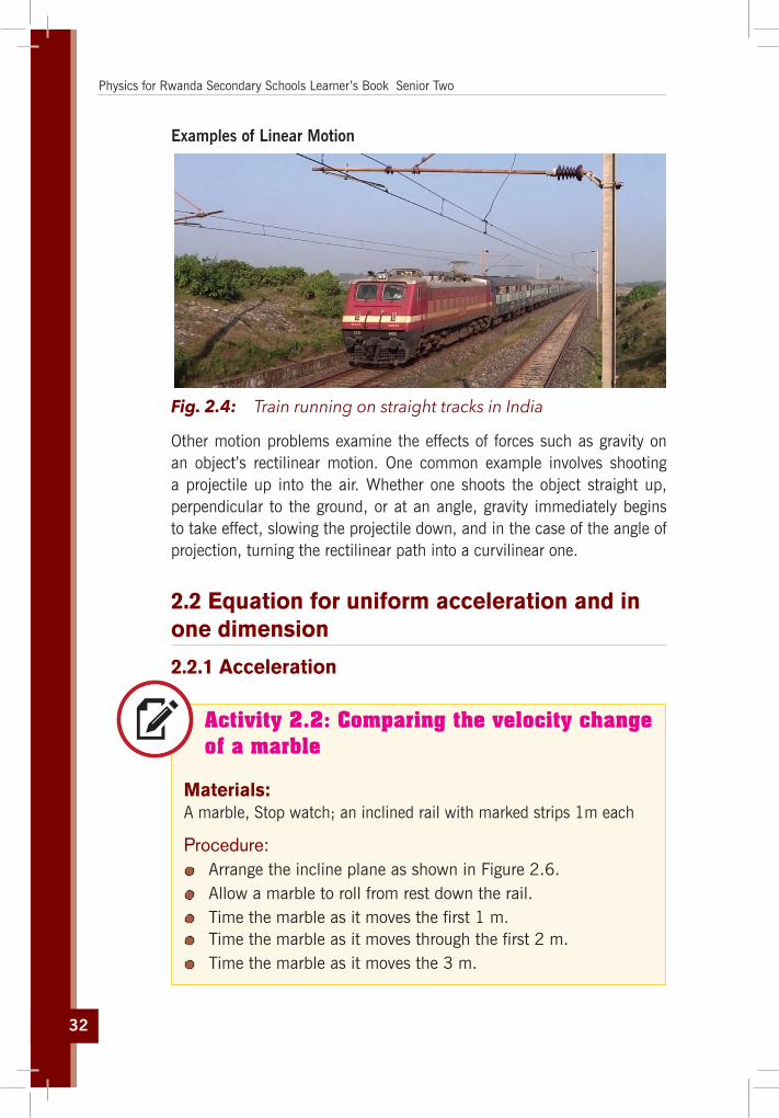
Fig. 2.4: Train running on straight tracks in India
Other motion problems examine the effects of forces such as gravity on an object’s rectilinear motion. One common example involves shooting a projectile up into the air. Whether one shoots the object straight up, perpendicular to the ground, or at an angle, gravity immediately begins to take effect, slowing the projectile down, and in the case of the angle of projection, turning the rectilinear path into a curvilinear one.
2.2 Equation for uniform acceleration and in one dimension
2.2.1 Acceleration
Activity 2.2: Comparing the velocity change of a marble
Materials:A marble, Stop watch; an inclined rail with marked strips 1m each
Procedure: Arrange the incline plane as shown in Figure 2.6. Allow a marble to roll from rest down the rail. Time the marble as it moves the first 1 m. Time the marble as it moves through the first 2 m. Time the marble as it moves the 3 m.

33
Unit 2: Quantitative Analysis of Linear Motion
Questions: 1. What is the average velocity as the marble moves the first 1m?2. What is the average velocity of the marble as it moves the
second 1 m?3. What is the average velocity of the marble as it moves the
third 1 m?4. Where is the marble moving fastest?5. Is the velocity increasing or decreasing?
marble
1m 2m
3mwood
Fig. 2.5: Movement of a marble on an inclined plane
When the velocity of a body is changing, the body is said to be accelerating. Acceleration is defined as the rate of change of velocity with time.
a = ∆v∆t
= vf – vi
tf – ti
where vf is the final velocity at time tf and vi is the initial velocity at time ti.
A
A
B
B
it
itft
ftt
xfv v=xiv v=
(a) (b)
xfv
xiv
x t∆
xv∆
xx
vat
∆=
∆xv
Fig. 2.6: A car, modeled as a particle, moving along the x axis
In Fig. 2.7 we have (a) A car, modeled as a particle, moving along the x axis from (A) to (B) has velocity vxi at t = ti and velocity vxf at t = tf. (b) Velocity–time graph for the particle moving in a straight line. The slope of
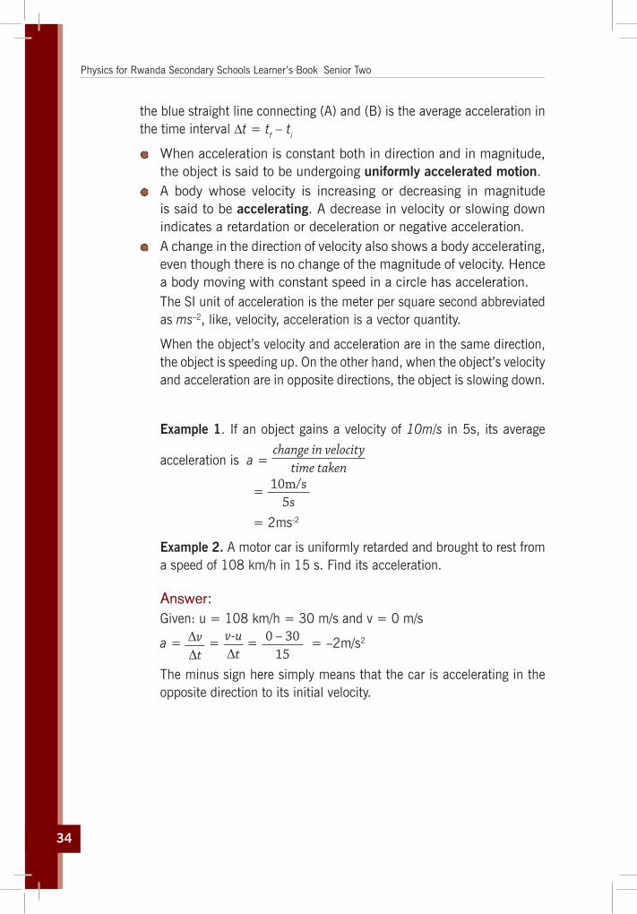
34
Physics for Rwanda Secondary Schools Learner’s Book Senior Two
the blue straight line connecting (A) and (B) is the average acceleration in the time interval ∆t = tf – ti
When acceleration is constant both in direction and in magnitude, the object is said to be undergoing uniformly accelerated motion.
A body whose velocity is increasing or decreasing in magnitude is said to be accelerating. A decrease in velocity or slowing down indicates a retardation or deceleration or negative acceleration.
A change in the direction of velocity also shows a body accelerating, even though there is no change of the magnitude of velocity. Hence a body moving with constant speed in a circle has acceleration.The SI unit of acceleration is the meter per square second abbreviated as ms–2, like, velocity, acceleration is a vector quantity.
When the object’s velocity and acceleration are in the same direction, the object is speeding up. On the other hand, when the object’s velocity and acceleration are in opposite directions, the object is slowing down.
Example 1. If an object gains a velocity of 10m/s in 5s, its average
acceleration is a = change in velocity
time taken
= 10m/s5s
= 2ms-2
Example 2. A motor car is uniformly retarded and brought to rest from a speed of 108 km/h in 15 s. Find its acceleration.
Answer: Given: u = 108 km/h = 30 m/s and v = 0 m/s
a = ∆v∆t
= v-u∆t
= 0 – 3015
= –2m/s2
The minus sign here simply means that the car is accelerating in the opposite direction to its initial velocity.

35
Unit 2: Quantitative Analysis of Linear Motion
Activity 2.3: Calculating the maximum speed
A car starts from rest and is accelerated uniformly at the rate of 2m/s2 for 6s. It then maintains a constant speed for half a minute. The brakes are then applied and the vehicle uniformly retarded to rest in 5s . Find the maximum speed reached in km/h and the total distance covered in meters.
2.2.2 Velocity with constant accelerationBy rearranging the equation for acceleration, we can find a value for the final velocity
a = ∆v∆t
a ∆t = ∆va ∆t = v-ua ∆t + u = v
Do not confuse acceleration and velocity. Acceleration tells us how fast the velocity changes, whereas velocity tells us how fast the position changes.
2.2.3 Displacement with constant accelerationFor an object moving with constant acceleration, the average velocity is equal to the average of the initial velocity and final velocity;
v = v + u2
To find an expression for the displacement in terms of the initial and final velocity, we can set the expressions for average velocity equal to each other:
v = ∆s∆t
= v + u2
Multiplying both sides of the equation by ∆t leaves us with an expression for the displacement of any object moving with constant acceleration:
∆S = ( u + v2
) ∆t
Substituting v = u + a∆t into (∆S = v + u2
∆t) gives:
∆S = 12
[u + a∆t + u]∆t ⇔ ∆S = u∆t + 12
a(∆t)2

36
Physics for Rwanda Secondary Schools Learner’s Book Senior Two
Example 1. A race car reaches a speed of 42m/s. It immediately then begins a uniform negative acceleration, using its braking system, and comes to rest 5.5s later. Find how far the car moves while stopping.
Answer: Use the equation for displacement; ∆s =(
u + vt )∆t
= 0 + 422
x 5.5m
= 115.5m
Example 2. A plane starting at rest at one end of a runway undergoes a constant acceleration of 4.8m/s2 for 15s before takeoff. What is its speed at takeoff? How long must the runway be for the plane to be able to take off?
AnswerUse the equation for the velocity of a constantly accelerated object:
v = u+ a∆t
= (0+ 4.8NS)m/s = 72m/s
Use the equation for the displacement:
∆S = u∆t + 12
a(∆t)2
=[0 +12
x 4.8 x (15)2]m = 540m
Let us quote the formulae that we can derive concerning constant acceleration and motion in one dimension:
a = constant
v = u + at
S = S0 + ut + 12
at
S = distance after object accelerates for a time, tS0 = initial distancev = velocity after object accelerates for time, tu = initial velocitya = acceleration and time t = time
Additional relations between displacement, velocity and acceleration can be derived.
We have v = u + at ⇔ v2 = u2 + 2uat + a2t2 ⇔ v2 = u2 + 2a(ut + at2
2)

37
Unit 2: Quantitative Analysis of Linear Motion
But
S = S0 + ut + 12
at2 ⇔ S – S0 = ut + 12
at2 we have v2 = u2 + 2a (S – S0 ) (4)
This relation is useful when time is not known explicitly
If we know any three of u, v, a, S and t the others can be found from these equations.
These formulae only apply to cases of particles moving under constant acceleration. If this condition does not apply to the situation under consideration, then you cannot use these formulae.
Sign Convention Before we start applying these formulae, let us introduce a sign convention. Since we are working in one dimension, there are only two directions we need to worry about. For instance, if we consider motion in a horizontal direction, the only two directions are left and right. Likewise, if we consider motion in a vertical direction, the only two directions are up and down.
Mathematically, we can denote the two directions with a sign. The convention that must be used for quantities associated with the body with respective motion below:
Horizontal Motion Vertical MotionRight is (+). Up is (+).Left is (-). Down is (-).
For example: If a rocket is moving up at the speed of 10,000m/s, we can just write the rocket’s velocity as 10,000m/s. If the rocket had been moving downward, then the sign infront of the 10,000m/s would have been negative, (-).
Example 1. What is the velocity of an object, at rest, if it experiences a constant acceleration of 10m/s2 to the right after a period of 3s?
Answer:The initial velocity of the object is because we stated that it was initially at rest.
The constant acceleration is a = 10m/s2 to the right. The time that the object accelerates is t = 3s.
Using velocity formula v = v0 + at gives:
v=0m/s + (10m/s2 ×3s)=30m/s

38
Physics for Rwanda Secondary Schools Learner’s Book Senior Two
The object will move at a velocity of 30m/s to the right after undergoing a constant acceleration of 10m/s2 to the right for 3s.
Example 2. As a bus comes to stop, it slows from 9.00m/s to 0.00m/s in 360s. Find the average acceleration of the bus.
Answer: v = vo – at o = 9m/s – a × 360
a x 360s = 9m/s
a = 9m/s
360 s
a = 140
m/s2
= 0.025m/s2
Example 3. Consider a ball thrown upward with an initial velocity of 20 m/s. What will its velocity be after 3s if it undergoes a constant acceleration of a = 10m/s2 downward?
a = –10m/s
vo = 20m/s
vo = u, the initial velocityFig. 2.7: Ball thrown upward
Answer:Since we are dealing with vertical motion, upward direction is (+) and downward direction is (-).
The initial velocity is u = 20m/s, the acceleration is a = –10m/s2 and the time is t = 3s
Let’s plug these given information values into the velocity formula and get our result.
From v = vo + at we have
v = 20m/s + [(–10m/s2) x 3s]
= 20 m/s - 30m/s
= –10m/s
39
Unit 2: Quantitative Analysis of Linear Motion
Gives v = u + at and gives v = 20m/s + (–10m/s2 × 3s) = –10m/s
The answer is, that the ball’s velocity is 10 m/s downward. The (-) sign is very important here because it tells us that the direction of the velocity is downward.
Note that in the free up and down motion of an object, the acceleration of that object a = g the acceleration due to the gravitational forces.
Activity 2.4: Calculating the maximum height
A stone is thrown vertically upwards with an initial velocity of 14m/s. Neglecting air resistance, find; a) The maximum height reached;
b) The time taken before it reaches the ground. (acceleration due to the gravity is 9.8m/s2)
2.3 Acceleration due to gravity and free fall
Activity 2.5: Gravity
Materials: A stop clock. Five stones of different masses between 0.5kg → 5kg. A long wooden pole.
Procedure: Measure out a distance of 2m from the floor of your laboratory
but against a pole. From the smallest stone to the biggest stone, drop the stones
one by one. Using the stop clock, find out how long each stone takes to reach the floor.
Repeat this three times for each stone and find out the average time for each stone.
Determine the average speed of each stone after falling for 2m.

40
Physics for Rwanda Secondary Schools Learner’s Book Senior Two
Questions:How fast did different objects fall? Grab a tennis ball and a basketball and drop them from the same height and the same time. What do you notice? How about a shoe and a ping pong ball?
It is well known that, in the absence of air resistance, all objects dropped near the Earth’s surface fall toward the Earth with the same constant acceleration under the influence of the Earth’s gravity (the pull of gravity which the earth exerts on the falling bodies). It was not until about 1600 that this conclusion was accepted. Before that time, the teachings of the great philosopher Aristotle (384 – 322 B.C.) had held that heavier objects fall faster than lighter ones.
Galileo Galilei a famous scientist, who lived in Italy (1564 - 1642), showed that all bodies, irrespective of their masses and nature, fall towards the Earth at the same rate. He further explained that the commonly observed difference in the rate of fall of heavy and light objects was due to the air resistance these objects experience due to their shapes and hence the differences vanished if the experiment was performed in vacuum.
Galileo’s observations were later verified by Sir Isaac Newton when he performed his famous feather and coin experiments (Fig. 2.9). He observed that the rate of fall of a feather and a coin in the long glass tubes was the same if the tubes was evacuated and different when air were allowed inside the tubes.
With air still in the tube With the air sucked outWith air still in the tube With the air sucked out
Fig. 2.8: Feather and coin experiment
The falling bodies undergo motion with uniform acceleration i.e. as they fall, their velocity increases by equal steps in equal time intervals. This acceleration, which the falling bodies have, is called acceleration due to gravity and is denoted by the letter, ‘g’. The acceleration due to gravity is the same for all objects, provided where there is very limited or no air resistance.

41
Unit 2: Quantitative Analysis of Linear Motion
The kind of fall where the bodies fall under the influence of gravity only regardless of its initial motion is called free fall motion. In free fall, the only outside force acting on the falling body is the pull of gravity with different masses.
The presence of air affects the motion of falling bodies partly through buoyancy and partly through air resistance. Thus two different objects falling in air from the same height will not, in general, reach the ground at exactly the same time. Because air resistance increases with velocity, eventually a falling body reaches a terminal velocity that depends on its mass, size, and shape, and it cannot fall any faster than that.
Questions For each stone, use the velocity formula and calculate the value of the acceleration.
What result have you determined?
What conclusions can you develop in relation to motion under gravity.
Its direction is always downward toward the centre of the Earth. Its magnitude varies from one place to another. The g is slightly greater at the poles (g = 9.832 m/s2) than at the equator (g = 9.780 m/s2), since the Earth is not a perfectly spherical shape. Its magnitude is approximately g = 9.80 m/s2
When a body is dropped then its subsequent motion is downward. Dropping means that the motion is under a constant acceleration of "g" downwards.
The falling object starts out at a velocity of zero and, with constant acceleration the value of velocity increases in a simple straight line.
Example 1. Let’s say you are standing next to a cliff and decide to drop a ball. What is the ball’s velocity after 4s?
Answer:From v = u–gt
v = u–gt
= 0–9.81m/s x 4s
= –39.32m/s
The negative sign shows this – the motion is downwards.

42
Physics for Rwanda Secondary Schools Learner’s Book Senior Two
Example 2. A stone dropped from the top of a building takes 6s to reach the ground below.
a) What is the height of the building?
b) How far will the stone fall during the fifth second of its falling?
Answer: a) Using the equation h = ut – gt2
2h = 0 – 10m/s 2 x (6s)2
2
= 360 m
2 = 180m
The negative sign indicates that the height of the building was calculated from the point of release of the stone downwards to the bottom of the building.
b) The fifth second begins immediately after the end of the fourth second and stops at the end of the fifth second.
For t = 4s, h1 = ut –gt2
2 = 0 – 10 x (4)2=
2 = –80m
for t = 5s, h2 = ut – gt2
2 = 0 – 10 x (5)2m
2 = –125m
The height the stone falls through in the fifth second is then given by:
∆t = h2 – h1
= –125 – (–80) = –45m.
The negative sign indicates that measurement was from up to down, following the motion of the stone.

43
Unit 2: Quantitative Analysis of Linear Motion
Activity 2.6: Quick check exercises
1. Jason hits volleyball so that it moves with an initial velocity of 6.0m/s straight upward. If the volley starts from 2.0m above the floor, how long will it be in the air before it strikes the floor? Assume that Jason is the last player to touch the ball before it hits the floor.
2. A stone is thrown upwards with an initial speed of 5m/s.a) What will its maximum height be?
b) When will it strike the ground?
c) Where will it be in 2s?
3. Suppose that a ball is dropped from a tower 70m high. How far will it have fallen after 1s, 2s, and 3s? Assume y is positive downward. Neglect air resistance.
Note: An object thrown downward or upward at a given location on the Earth and in the absence of air resistance, all objects fall with the same place acceleration. (Equator), (pole)
Example 1. A man fires a stone out of a slingshot directly upwards. The stone has an initial velocity of 15m/s. How long will it take for the stone to return to the level he fired it at?
Answer: Using the equation
h = ut gt2
2 we have: h = ut – gt2
2
0 = 15t – 10t2
2
10t2
2 = 15t
10t2
= 15s
10t = 30s t = 3s

44
Physics for Rwanda Secondary Schools Learner’s Book Senior Two
Example 2. A falling body travels 68m in the last second of its free motion: Assuming that the body started from rest, determine how long it took to reach the ground and the altitude from which the body fell.
Answer: A convenient axis is one with origin at the point of dropping and pointing downward. Let t1 be the time one second before hitting the ground and h1 the corresponding distance travelled. Let t2 be the time to hit the ground and h2 the corresponding distance travelled. (Use g = 9.8 m/s2)
Then t2 – t1 = 1 s and h2 – h1 = 68m.
From the equation h = ut – gt2
2
then h1 = 0 – 9.8 x t1
2 2
= -4.9t12
Similarly h2 = -4.9t22
But h2 – h1 = 68m
and t2 = t1 + 1
Then –4.9 (t1 + 1)2 –4.9t12 : –68
–4.9t2 – 9.8t1 –4.9 = –49t12 – 68
9.8t1 = 68 – 4.9
9.8t1 = 63.1
t1 = 6.48
using t2 = t1 + 1
t2 = 6 – 4 + 1
= 7.4 s
The altitude is then h2 = 4.9m/s2 (7.4s)2 = 268m
Activity 2.7: Quick check exercises
1. A person throws a ball upward into the air with an initial velocity of 5.0 m/s. Calculate:a) How high it goes.
b) How much time it takes for the ball to reach the maximum height.

45
Unit 2: Quantitative Analysis of Linear Motion
c) How long the ball is in the air before it comes back to his hand.
d) The velocity of the ball when it returns to the thrower’s hand.
e) At what time, the ball passes a point 8.00m above the thrower’s hand.
We are not concerned here with the throwing action, but only with the motion of the ball after it leaves the thrower’s hand.
2. A stone is dropped from a balloon that is descending at a uniform rate of 0.2m/s when it is 1000m from the ground. a) Calculate the velocity and position of the stone after 10s
and the time it takes the stone to hit the ground.
b) Solve the same problem as for the case of a balloon rising at a velocity of 0.1m/s.
2.4 Determination of G: Use of a simple pendulum
Many things in nature swing in a periodic motion. That is, they vibrate. One such example is a simple pendulum. If we suspend a mass at the end of a piece of string, and we allow the mass to swing up and down along the vertical axis, we have a simple pendulum. Here, the to and fro motion represents a periodic motion used in times past to control the motion of clocks.
Rigidsupport
Longthread
Bob(Metal ball)
(a) Simple pendulum (b) Motion of a simple pendulum
Mean positionor
Centre position
ExtremepositionA
L T
C
A
B
S
Extremeposition
Fig. 2.9: A Pendulum bob

46
Physics for Rwanda Secondary Schools Learner’s Book Senior Two
Such oscillatory motion is called simple harmonic motion. It was Galileo who first observed that the time a pendulum takes to swing back and forth through small angles depends only on:
The length of the pendulum, the time of this to and fro motion, called the period, and does not depend on the mass of the pendulum. Another factor involved in the period of motion is, the acceleration due to gravity (g), which on the earth is 9.8m/s2 at the equator.
A long pendulum has a greater period than a shorter pendulum.
Fig. 2.10: A Pendulum bob swinging
With the assumption of small angles of projection, the frequency and period of the pendulum are independent of the initial angular displacement. All simple pendulums have the same period regardless of their initial angle (and regardless of their masses of the bobs).
The period, T for a simple pendulum does not depend on the mass or the initial angular displacement, but depends only on the length, L of the string and the value of the gravitational field strength, g;
T = 2π Lg

47
Unit 2: Quantitative Analysis of Linear Motion
Activity 2.8: Measuring gravity of any given place
Referring to the above concept, use the formula given below and try to answer the questions.
Materials: Strings A pendulum bob (mass) Masses of 10, 20, 30, 40 and 50 gms Stop watch A paper and a pencil Metre rule Retort stand
Procedure:1. The period, T of a simple pendulum (measured in seconds) is
given by the formula:
T = 2π Lg
(1)
T = Time for 30 oscillations30 oscillations
(2)
2. Using equation (1) to solve for “g”, L is the length of the pendulum (measured in meters) and g is the acceleration due to gravity (measured in meters/sec2). Now with a bit of algebraic rearranging, we may solve Eq. (1) for the acceleration due to gravity g. (You should derive this result on your own).g = 4π2 L
T2 (3)
3. Measure the length of the pendulum from the clamp of the retort stand to the middle of the pendulum bob. Record the length of the pendulum in a table. Attach a mass of 10 gms to the end of the given string. Clip the other end of the string to a rigidly fixed retort stand.
4. Set the pendulum in motion until it completes 30 to and fro oscillations, and for 4 sets of dings, record this time and determine the period.

48
Physics for Rwanda Secondary Schools Learner’s Book Senior Two
5. You will make a total of eight measurements for g using two different masses at four different values for the length, L.Note: π = 3.14, 4 π² = 39.44
L (meters) Mass Time for 30 oscillations
Period T (seconds)
T2 g = 39.44L/T2
Average value of g = ––––––––––––––––
Questions:1. From your data what effect does changing the mass have on
the period?2. Would you conclude that Galileo was correct in his observation
that the period of a simple pendulum depends only on the length of the pendulum?
3. On the moon, the acceleration due to gravity is one-sixth that of earth.
What effect, if any, would this have on the period of a pendulum of length, L?
How would the period of the pendulum on the moon differ from an equivalent one on earth?
2.5 Unit 2 assessment
1. a) Is an object accelerating if its speed is constant? b) Is an object accelerating if its velocity is constant?
2. If you know the position vectors of a particle at two points along its path and also know the time it took to get from one point to the other, explain how you will determine the particle’s instantaneous velocity and its average velocity.
3. The average velocity of a particle moving in one dimension has a positive value. Is it possible for the instantaneous velocity to have been negative at any time in the interval? Suppose the

49
Unit 2: Quantitative Analysis of Linear Motion
particle started at the origin x = 0. If its average velocity is positive, could the particle ever have been in the - x region of the axis?
4. If the average velocity of an object is zero in some time interval, what can you say about the displacement of the object for that interval?
5. Can the magnitude of the instantaneous velocity of an object ever be greater than the magnitude of its average velocity?
6. If the average velocity is non-zero for some time interval, does this mean that the instantaneous velocity is never zero during this interval? Explain.
7. If the velocity of a particle is non-zero, can its acceleration be zero? Explain.
8. A stone is thrown vertically upward from the top of a building. Does the stone’s displacement depend on the location of the origin of the coordinate system? Does the stone’s velocity depend on the origin? (Assume that the coordinate system is stationary with respect to the building). Explain.
9. If the velocity of a particle is zero, can its acceleration be nonzero? Explain.
10. Two cars are moving in the same direction in parallel lanes along a highway. At some instant, the velocity of car, A exceeds the velocity of car, B. Does this mean that if the acceleration of the car reduces, A is greater than that of car, B? Explain.
11. You are standing on top of a cliff and you decide to throw a stone upward at a speed of. After 40s, you see the stone hit the base of the cliff. How far down is the base of the cliff? In addition, what is the velocity of the stone when it reaches the base of the cliff?
12. A feather and a coin are released from the same height at the same time. Which one reaches the ground first? Explain why they do not reach the grand at the same time.
13. How long will it take a car to accelerate from 10m/s to 35m/s at a constant acceleration of 5m/s2 in a straight line.
14. Imagine a ball that is thrown upward with a velocity of 5m/s. If the ball experiences a downward constant acceleration of 10m/s2, how long will it take for its velocity to reach 25m/s downward?

50
Physics for Rwanda Secondary Schools Learner’s Book Senior Two
15. Assume there is a jet plane initially moving to the right at 10 m/s. Furthermore, then it accelerates for 90s and ends up with a speed of 20m/s but moving to the left. Assuming the acceleration was constant, what is the constant acceleration the jet plane undergoes?
16. A car accelerates along a straight road from rest to 75km/h in 5.0s. What is the magnitude of its average acceleration?
17. An car with an initial speed of 4.3m/s accelerates at the rate of 3.0m/s2. Find the final speed and the displacement after 5.0s.
18. A ball is thrown upwards with an initial velocity u. After 3s the velocity of the ball upwards is determined to be 10m/s. Calculate the value of the initial velocity u. Use g = 10m/s2.
19. A car with an initial speed of 23.7km/h accelerates at a uniform rate of 0.92m/s2 for 3.6s. Find the final speed and the displacement of the car during this time.

Mechanics

52

53
Unit3
Frictional Force
Key unit competence The learner should be able to explain the effects of friction and its importance in life.
My goalsBy the end of this unit, I will be able to:
explain the nature of frictional force. explain effects of frictional force. discuss advantages and disadvantages of frictional forces. measure static and dynamic coefficients friction. describe technological applications of frictional force. identify factors affecting frictional force. identify methods of reducing friction. solve problems on frictional force.
Key concepts 1. What is needed to describe frictional force?2. Which factors cause friction?3. Discuss different types of friction?4. How is friction advantageous in real life?5. What are the disadvantages of friction in real life?6. How can you overcome friction?7. How can you increase friction?

54
Physics for Rwanda Secondary Schools Learner’s Book Senior Two
Vocabulary
Frictional force, resistance force, weight, roughness, smoothness, coefficient of friction, viscosity, air resistance.
y Reading strategy
As you read this section, re-read the paragraphs that contain definitions of key terms. Use all the information you have learnt to write a definition of each key term in your own words. Then practice more examples and activities to help you in performing your assessment.
3.1 Nature of frictional force
Activity 3.1: Experiencing friction while pushing a desk
Carry out the following activity and discuss the results observed.
Fig. 3.1: Pushing a box
1. Push a heavy object (such as the teacher’s desk) gradually till it moves at a steady speed.
2. Carefully describe what you felt.3. Try to define friction force in your own words.4. Discuss friction and find out if it is good or bad giving typical
examples.5. Plan how you would reduce friction between the desk and
the floor.
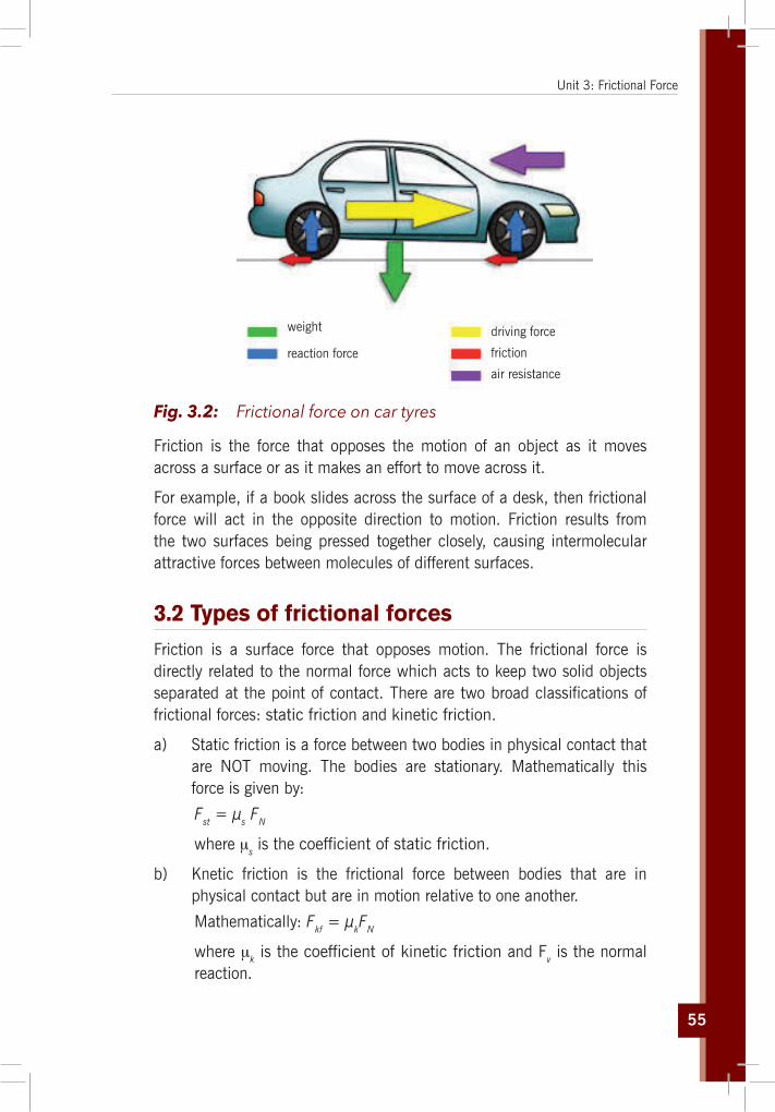
55
Unit 3: Frictional Force
weight
reaction force
driving force
friction
air resistance
Fig. 3.2: Frictional force on car tyres
Friction is the force that opposes the motion of an object as it moves across a surface or as it makes an effort to move across it.
For example, if a book slides across the surface of a desk, then frictional force will act in the opposite direction to motion. Friction results from the two surfaces being pressed together closely, causing intermolecular attractive forces between molecules of different surfaces.
3.2 Types of frictional forces
Friction is a surface force that opposes motion. The frictional force is directly related to the normal force which acts to keep two solid objects separated at the point of contact. There are two broad classifications of frictional forces: static friction and kinetic friction.
a) Static friction is a force between two bodies in physical contact that are NOT moving. The bodies are stationary. Mathematically this force is given by:
Fst = μs FN
where μs is the coefficient of static friction.
b) Knetic friction is the frictional force between bodies that are in physical contact but are in motion relative to one another.
Mathematically: Fkf = μkFN
where μk is the coefficient of kinetic friction and Fv is the normal reaction.

56
Physics for Rwanda Secondary Schools Learner’s Book Senior Two
3.3 The laws of solids friction
Experimental results on solid friction are summarised in the laws of friction which state:
a) The frictional force between two surfaces opposes their relative motion.
b) The frictional force is independent of the area of contact of given surfaces when the normal reaction is constant.
c) The limiting frictional force is proportional to the normal reaction for the case of static friction. The frictional force is proportional to the normal reaction for the case of kinetic (dynamic) friction, and is independent of the relative velocity of the surfaces.
The symbol μ represents the coefficient of sliding friction between the two surfaces and depends on the roughness of the surfaces e.g. for wood on wood μ = 0.4, for steel on steel μ = 0.2
Experimentally for most surface interfaces, the coefficient of kinetic friction is less than the coefficient of static friction as shown in the following table.
Table 3.1: CoefficientsofFriction
μS μK
Steel on steel 0.74 0.57
Aluminum on steel 0.61 0.47
Copper on steel 0.53 0.36
Rubber on concrete 1.0 0.8
Wood on wood 0.25 – 0.5 0.2
Glass on glass 0.94 0.4
Ice on ice 0.1 0.03
3.4 Effects of friction
From the definition of friction force, find at least five different places where friction can be observed. Thus, answer to the following questions:

57
Unit 3: Frictional Force
Questions: Discuss and explain the effects of friction in each of the cases you
mention above. How would you decrease those effects of friction observed?
Friction tends to generate heat energy. Friction reduces the speed of moving objects and therefore
causes loss of energy. Friction damages sliding surfaces that are in contact. Friction causes wear and tear in moving parts.
3.5 Advantages and disadvantages of friction
Friction is very important because it enables us to move. If there was no friction, our feet would slip, just as they do on smooth surface. Friction also enables us to write, to make fire, the brakes of cars or bicycles use friction to slow them down. It is also a nuisance because it wears the soles of our shoes and the car tyres, causes the unnecessary heat and undesirable noise, lowers efficiency of machines.
In a machine such as a bicycle, friction hinders the wheels from turning freely. This is also true in other machines like cars, lorries, buses. This means that they use more fuel in order to move because they have to overcome friction.
3.6 Factors affecting friction and how to reduce it
Friction depends upon the nature of the two surfaces in contact and the degree to which they are pressed together. Experiments show us that the force of friction between two surfaces depends:
The nature of the surfaces. Rough surfaces give more friction than smooth ones. So if we want to make a machine in which very little friction acts, we make the surfaces smooth.
The force pressing the surfaces together. The bigger this force is, the greater the force of friction.
The type of shape also, where some shapes meet less resistance than others. The shapes which meet the least resistance are said to be streamlined.

58
Physics for Rwanda Secondary Schools Learner’s Book Senior Two
The size of frictional force also depends the speed of the moving object.
The frictional force or resistance met by an object through air is always much less than it experiences when moving through a liquid.
The moving machine parts are always oiled or greased in order to reduce friction. This helps the moving parts to slip more easily over each other. The liquid is usually oil, which we refer to as a lubricant (reduce friction by separating two contacting surfaces with an intermediate layer of softer material). And we call the effect lubrication. The 2nd method involves reducing the roughness of the surfaces in contact; we can also use a ball or roller bearings.
3.7. Other resistance forces
Tensional forces
Activity 3.2: Investigation of tension force
Material: Rope Six stones of different masses Spring balance (Newton meter).
Procedure: Measure the mass and the weight of each stone using a spring
balance. Tie the rope on the stone and hang it on the spring balance
fixed on a ceiling and note the reading on the spring balance. Change the stone and repeat the observations. Discuss in groups about the nature of forces involved in your
experiment.
Questions:1. What force did you observe in the experiment?2. Where may this type of force appear?

59
Unit 3: Frictional Force
Free-body diagram
T
T
T
w
wm
The tension force T in Fig. 3.3, is the force which is transmitted through a string, rope, cable or wire which are massless, frictionless, unbreakable, and unstretchable when it is pulled tight by forces acting from opposite ends. The tension force is directed along the length of the wire and pulls equally on the objects on the opposite ends of the wire.
Fig. 3.3: Tension force
3.7.1 Normal Forces
Activity 3.3: Investigating the normal force
Materials: Five books Two wooden blocks A meter ruler
Procedure: Arrange the blocks and the ruler as a bench as follows in
Fig 3.4:
wooden block 2
ruler
wooden block 1
Fig. 3.4: Wooden blocks and the ruler laid in the form of a table.

60
Physics for Rwanda Secondary Schools Learner’s Book Senior Two
Lay the five books on the ruler at its middle and note your observations.
Remove some books and note the change; then discuss the changes.
Questions:1. What are the forces involved in the experiment?2. Which force is opposing the books not to break the ruler
down?
Table
FloorF
F
F
F BG
BT
G
N
Book
Fig. 3.5: Normal forces
The normal force is a component of the contact force that is perpendicular to the surface of contact exerted on an object by the surface (of a table, wall etc).
Weight
FN
Weight
FN
a) b)
Fig. 3.6
The normal force here represents the force applied by the table against the book that prevents it (the book) from sinking through the table.
The normal force acts as resistive force that balances with the weight of the body in vertical direction as shown in fig. 3.5

61
Unit 3: Frictional Force
3.7.2 Air resistance forces
Activity 3.4: Investigating the air resistance
Take the case of the parachute as in fig. 3.7 and answer to the following questions.
Fig. 3.7: Air resistance in parachutes
1. What is happening to the parachute?2. Name the forces involved in the downward motion of the
parachutist?
The air resistance is a special type of frictional force which acts upon objects as they travel through the air. The force of air resistance is often observed to oppose the motion of an object. This force will frequently be neglected due to its negligible magnitude. It is most noticeable for objects which travel at high speeds (e.g., a skydiver or a downhill skier) or for objects with large surface areas.

62
Physics for Rwanda Secondary Schools Learner’s Book Senior Two
3.7.3 Spring Force
Activity 3.5: Investigating the spring force
Materials: Spring balance Object (Stone (s))
Procedures: Hang the spring balance in a fixed position. Put the stone of mass, m and notice the change on the spring
balance. Change the stone and continue to note your observations.
Questions:1. What are the forces involved in this system?2. Which force does the spring exert on the stone?
Fig. 3.8: Spring forces
The spring force (Elastic force) is the force exerted by a compressed or stretched spring upon any object which restores its original position. An object which compresses or stretches a spring is always acted upon by a force the object to its rest or equilibrium position. The spring for Fk acts as a resistive force as shown in the figure 3.8.

63
Unit 3: Frictional Force
3.7.4 Applied forces
Activity 3.6 Investigating applied force
Take the case of a man pushing the box as in fig.3.9. and answer the following questions:
1. What is being done?2. Which forces are involved in the process?3. Name the force the man is using to push the box.
f
Fp
Fig. 3.9: Applied forces
An applied force Fp is a force in an action on the body that makes it to move or tend to move. The fig. 3.9 above shows a person pushing a body along an inclined plane. The push is the applied force acting upon the body. The force that resists (opposes) motion in the figure is denoted by f.
3.7.5 Magnetic forces
This type of force acts between poles of magnets (Fig. 3.10). The magnetic force is either a pull or a push. For example, two magnets can exert a magnetic pull on each other even when separated by a distance of a few centimeters. Like poles repel (push) and unlike poles attract (pull) each other.
Fig. 3.10: Magnetic forces

64
Physics for Rwanda Secondary Schools Learner’s Book Senior Two
3.7.6 Gravitational forcesThe force of gravity is the force with which the earth, moon, or other massively large object attracts another object towards itself. All objects upon earth experience a force of gravity which is directed "downward" towards the center of the earth. The force of gravity on earth is always equal to the weight of the object as found by the equation:
FG = mg
Even when your feet leave the earth and you are no longer in physical contact with the earth, there is a gravitational pull between you and the Earth.
3.8 Unit 3 assessment
1. Fill in the blanks.(a) Friction opposes the ________ between the surfaces in contact
with each other.
(b) Friction depends on the _________ of surfaces.
(c) Friction produces _________.
(d) Sprinkling of powder on the carrom board ________ friction.
(e) Sliding friction is ________ than the static friction.
2. Four children were asked to arrange forces due to rolling, static and sliding frictions in a decreasing order. Their arrangements are given below. Choose the correct arrangement.(a) rolling, static, sliding
(b) rolling, sliding, static
(c) static, sliding, rolling
(d) sliding, static, rolling
3. Alida runs her toy car on a dry marble floor, wet marble floor, a newspaper and a towel spread on the floor. The force of friction acting on the car on different surfaces in increasing order will be;(a) Wet marble floor, dry marble floor, newspaper and towel.
(b) Newspaper, towel, dry marble floor, wet marble floor.
(c) Towel, newspaper, dry marble floor, wet marble floor.
(d) Wet marble floor, dry marble floor, towel, newspaper.
4. Suppose your writing desk is tilted a little. A book kept on it starts sliding down. Show the direction of frictional force acting on it.

65
Unit 3: Frictional Force
5. You spill a bucket of soapy water on a marble floor accidentally. Would it make it easier or more difficult for you to walk on the floor? Why?
6. Explain why athletes use shoes with spikes.7. Ineza has to push a lighter box and Shema has to push a similar
heavier box on the same floor. Who will have to apply a larger force and why?
8. Explain why sliding friction is less than static friction.9. Give examples to show that friction is both a friend and a foe.10. Explain why objects moving in fluids must have special shapes.11. A 5kg object is sliding to the right and encountering a friction
force which slows it down. The coefficient of friction (μ) between the object and the surface is 0.1. Determine the force of gravity, the normal force, the force of friction. (Neglect air resistance).
Fnorm =
Fapp =
a =
Fnet =
Fgrav =
Ffrict =
μ = 0.1m = 5 kg
12. A rightward force is applied to a 10-kg object to move it across a rough surface at constant velocity. The coefficient of friction between the object and the surface is 0.2. Use the diagram to determine the gravitational force, normal force, applied force, frictional force, and net force. (Neglect air resistance).
Fnorm =
Fapp =
Fnet =
Fgrav =
Ffrict =
μ = 0.2m = 10 kga = 0 m/s/s
13. A rightward force is applied to a 5kg object to move it across a rough surface with a rightward acceleration of 2m/s2. The coefficient of friction between the object and the surface is 0.1. Use the diagram to determine the gravitational force, normal force, applied force, frictional force, and net force. (Neglect air resistance).

66
Physics for Rwanda Secondary Schools Learner’s Book Senior Two
Fnorm =
Fapp =
Fnet =
Fgrav =
Ffrict =
μ = 0.1
m = 5 kga = 2m/s/s, right
14. Eduardo applies a 4.25N rightward force to a 0.765kg book to accelerate it across a table top. The coefficient of friction between the book and the table top is 0.410. Determine the acceleration of the book.

Mechanics

68

69
Unit4
Density and Pressure in Solids and Fluids
Key unit competenceThe learner should be able to define pressure and explain factors affecting it.
My goalsBy the end of this unit, I will be able to:
define and explain the pressure as a relationship of force acting on a surface area.
identify force and area as factors affecting pressure in solids. give the relationship between force, pressure and area. explain how pressure varies with force and the area of contact. describe liquid (mercury) in glass barometer. explain floating and phenomena. describe how to measure atmospheric pressure. carry out calculations using the equation.
Pressure = force/area and P = ρgh.
explain the variation in atmospheric pressure with altitude. explain the change in pressure by reducing or increasing area of
contact and vice versa. measure atmospheric pressure using a barometer, liquid in
glass barometer.

70
Physics for Rwanda Secondary Schools Learner’s Book Senior Two
explain the functioning of aneroid barometer. describe and explain pressure transmission in hydraulic systems. explain functioning of a hydraulic press and hydraulic brakes.
Key concepts 1. How experimentally can one determine the effect of force exerted
on a solid?2. How can one define pressure in a fluid?3. How can pressure in liquids be measured?4. What instrument should be used in measuring pressure?5. Where can pressure in solids and liquids be applied in real life?
Vocabulary
Pressure, atmospheric pressure, fluids, hydrostatic pressure, barometer, manometer.
y Reading strategy
As you read this unit – mark the paragraphs that contain definitions of key terms. Use all the information to write a definition of each key term in your own words. Perform calculations related to pressure in solids and fluids.
4.1 Force exerted by solids
Activity 4.1: Investigation pressure of a solid
Materials: One concrete brick Balance A pile of sand A ruler A long beam of wood

71
Unit 4: Density and Pressure in Solids and Fluids
Procedures:Measure the mass (m) of the brick and calculate its weight (w = mg).
Pour two bucketfuls of sand outside your laboratory such that it forms a pile as shown in (i).
Use the long wooden beam to spread the sand such that you have a fairly large plain surface on top of the sand pile, as shown in (ii).
Take measurement of dimensions of one of the large surface side and calculate its area A1.
Take measurement of the dimensions of the small side and calculate its area A2.
Gently place the brick in the sand on its big side and let it rest on the sand for 15s. Carefully remove the brick from the sand. Note the depression formed on the sand and carefully measure its depth. Measure the depth at four different places and determine the average depth of the depression on the sand left by the brick. Calculate pressure exerted by the brick using P1 = W
A2 Gently place the brick on the sand on its smaller side but at a
point away from the first experiment. Calculate the pressure exerted by the brick P2 = W
A2
Compare and discuss the result obtained.
(i) Sand pile
(ii) Levelled sand pile
Fig. 4.1: Force exerted by a solid

72
Physics for Rwanda Secondary Schools Learner’s Book Senior Two
If the force is concentrated on a small area, it will exert higher pressure than if the same force is distributed over a larger surface area.
As an example of varying pressures,
A finger can be pressed against a wall without making any lasting impression; however, the same finger pushing a thumbtack can easily penetrate the wall. Although the force applied to the surface is the same, the thumbtack applies more pressure because the point concentrates that force into a smaller area.
If we try and cut a fruit with the flat side of the knife it obviously won’t cut. But if we take the sharp side, it will cut smoothly. The reason is, the flat side has a greater surface area(less pressure) and so it does not cut the fruit. When we take the thin side, the surface area is very small and so it cuts the fruit easily and quickly.
A bus or truck is heavy. It may have large tyres, so that its weight is spread over a large area. This means that the pressure on the ground is reduced; so it is less likely to sink in soft ground. This is one example of a practical application of pressure.
4.2 Definition and units of pressure
Pressure (symbol “p”) is the force acting normally per unit area applied in a direction perpendicular to the surface of an object. Gauge pressure is the pressure relative to the local atmospheric or ambient pressure. The pressure is directly proportional of force and proportional of square area. In mathematical terms, pressure can be expressed as:
p = FA
The pressure within a fluid (gas or liquid) is a scalar quantity—that is, it has magnitude but no particular direction associated with it in space.
Pressure arises from two fundamentally different kinds of sources: ambient and localised.
1. Ambient sources of pressure are usually a gas or a liquid in which an entity is immersed, such as a human being on the surface of the earth or a fish in a stream or lake. Life forms are generally insensitive to ambient pressures and become aware of the source of that pressure when currents become strong enough that the fluid exerts a non-uniform localised pressure on the life form, such as when the wind blows.

73
Unit 4: Density and Pressure in Solids and Fluids
2. Localised pressure sources are usually discrete objects, such as the finger pressing on the wall, or the tyres of a car pressed against the pavement. A liquid or gas can become the source of a localised pressure if either of them is forced through a narrow opening.
4.2.1 Unit of pressure The unit is the pascal and is named after Blaise Pascal, the eminent French mathematician, physicist, and philosopher noted for his experiments with a barometer, an instrument to measure air pressure. The name Pascal was adopted for the SI unit Newton per square meter by the 14th CGPM in 1971.
The Pascal (symbol: Pa) is the SI derived unit of pressure. It is a measure of force per unit area, equivalent to l Pa ≡ 1 N/m2 ≡ 1 kg/(m·s2).
The Pascal is perhaps best known from meteorological barometric pressure reports, where it occurs in the form of hectopascals or millibar (1hPa ≡ 100 Pa ≡ 1 mbar).
barye ≡ 1 μbar = 1 dyn/cm2
The standard atmosphere (atm) of pressure is approximately equal to air pressure on earth above mean sea level and is defined as:
In 1985, the International Union of Pure and Applied Chemistry (IUPAC) recommended that standard atmospheric pressure should be harmonised to 100,000 Pa = 1 bar = 750 Torr. Another unit for pressure measurement is millimeters of mercury (.1 mmHg = 9.80669Pa)We use a manometer to measure pressure in liquids and a barometer to measure air pressure.
Activity 4.2: Using a Manometer Manometer Water
Beaker A ruler (Optional)
Procedures:Try to refer to the Fig. 4.2 and do the following:
a) Pour water into the beaker.b) Note the level of the manometer liquid.c) Lower the manometer nozzle in water.d) Note the change in the level of the manometer liquid.e) Lower it deeper than before and note the new changes.

74
Physics for Rwanda Secondary Schools Learner’s Book Senior Two
Questions:1. What changes are you observing?2. Discuss the meaning and the cause of that change.3. Prove that liquids exert pressure on a body submerged in.
Fig. 4.2: A Manometer
The figure above is a simple pressure gauge and it measures differences in pressure exerted at the two ends of the apparatus. It is called a Manometer. The mouth of a thistle funnel is tightly covered with a thin plastic sheet. The thistle funnel is connected to a U-tube manometer containing water, by rubber tubing.
Now, lower the mouth of the funnel into a glass vessel containing water. You will notice that the deeper it goes; greater is the difference in the levels of the water in the manometer. This indicates that the pressure in a liquid increases with depth.
Repeat the experiment by turning the thistle funnel in different directions keeping the depth constant. You will observe that as long as the depth remains the same, there is no change in the level of the water in the manometer. Thus, the pressure exerted by a liquid at a given depth is the same in all directions.
Now, lower the thistle funnel to the same depth in a number of liquids having different densities. You will notice that in liquids having greater density, the pressure at the same depth is greater. This indicates that the greater the density of the liquid, the greater the pressure at the same depth.

75
Unit 4: Density and Pressure in Solids and Fluids
4.3 Static fluid pressure
The pressure exerted by a static fluid depends only upon the depth of the fluid, the density of the fluid, and the acceleration of gravity.
The pressure in a static fluid arises from the weight of the fluid and is given by the expression:
Pstaticfluid = ρf gh
Where ρ is the density of fluid; g is acceleration of gravity; and h is depth
of fluid.
The pressure from the weight of a column of liquid of area A and height h is:
V = hA = volume
weight = mg
Static fluid pressure does not depend on theshape, total mass, or surface area of the liquid.
Pressure = weightarea
mg pVgpgh
pghP =h
h A A== =
h h
P1
P2
Fig. 4.3: Pressure in liquid
The most remarkable thing about this expression is what it does not include. The fluid pressure at a given depth does not depend upon the total mass or total volume of the liquid. The above pressure expression is easy to understand for the straight, unobstructed column, but not obvious for the cases of different geometry which are shown.
Because of the ease of visualising a column height of a known liquid, it has become common practice to state all kinds of pressures in column height units, like mmHg. Pressures are often measured by manometers in terms of a liquid column height.

76
Physics for Rwanda Secondary Schools Learner’s Book Senior Two
4.3.1 Fluid pressure calculation
h
P1
P2
A
Fluid column height in the relationship with pressure difference is given by:
Pressure difference∆P = P2 – P1
= eh2g – eh1g= ehg – 0= eng
Note: The pressure P1 is zero because h1 = 0
Static fluid pressure is dependent on density and depth only and independent of total mass, weight, volume, etc. of the fluid.
Fig. 4.4: Pressure at a depth h P = ρgh
4.4 Atmospheric pressure
4.4.1 Measuring atmospheric pressure
760 mm column of mercury needed to
Pressure of mercury
Pressure of air
balance pressure of air at sea level
h
The atmospheric pressure is the weight exerted by the overhead mass of air on a unit area of surface. It can be measured with a mercury barometer, consisting of a long glass tube full of mercury inverted over a pool of mercury:
Fig. 4.5: Mercury barometer
When the tube is inverted over the pool, mercury flows out of the tube, creating a vacuum in the head space, and stabilises at an equilibrium height, h over the surface of the pool. This equilibrium requires that the pressure exerted on the mercury at two points on the horizontal surface of the pool, (inside the tube) and (outside the tube), be equal. The pressure

77
Unit 4: Density and Pressure in Solids and Fluids
at the point inside the tube is that of the mercury column overhead, while the pressure at that point is that of the atmosphere overhead. We obtain, from measurement of h,
P = eHg gh
where ρHg = 13.6 gcm–3 is the density of mercury and g = 9.8ms–2 is the acceleration of gravity. The mean value of h measured at sea level is 76.0 cm, and the corresponding atmospheric pressure is 1.013 × 10⁵ kg m–1 S–2 in SI units. The most commonly used pressure unit is the atmosphere (atm) (1atm = 1.013 × 10⁵ Pa) the bar (b)
(1 b = 1 × 10⁵ Pa), the millibar (mb) (1 mb = 100 Pa) and the torr.
(1 torr = 1 mm Hg = 134 Pa) The use of millibars is slowly giving way to the equivalent SI unit of hectoPascals. The mean atmospheric pressure at sea level is given equivalently as;
P = 1.013 × 10⁵ Pa = 1013hPa = 1013mb = 1 atm = 760torr.
R is the mean height of the atmosphere from the surface of earth.
4.4.2 Mass of the atmosphereThe global mean pressure at the surface of the Earth is slightly less than the mean sea-level pressure because of the elevation of land. We deduce the total mass of the atmosphere ma:
ma = 4π R2 Ps
g
Centre of
earth
Earth
Maximum height
for Atmosphere
R = R2 – R1
R2R1
R
Na = ma
Ma
= 1.8 × 10²⁰ moles.

78
Physics for Rwanda Secondary Schools Learner’s Book Senior Two
4.4.3 Torricelli’s experiment
Mercury
Atmosphericpressure
760 mm(29.92 in)
Vacuum
Glass tube
Fig. 4.6: Torricelli experiment of a simple mercury barometer
Torricelli’s experiment was a curious project made in 1643 by the Italian physicist and mathematician Evangelista Torricelli (1608-1647) in a laboratory that attained to measure the atmospheric pressure for the first time.
Process:Torricelli filled a 1 metre long tube with mercury, (closed at one end) and inverted it on a tray full of mercury. Immediately the column of mercury went down several centimetres, remaining static at some 76cm (760mm) of height.
As it was observed that the pressure was directly proportional to the height of the mercury column (Hg), the millimetre of mercury was adopted as a measurement of pressure.
That way, the pressure corresponded to a column of 760mm.
Conclusion:The column of mercury did not fall due to the fact that the atmospheric pressure exerted on the surface of the mercury was able to balance the pressure exerted by his weight.
760 mmHg = 1 atm1 atm = 1.013 mbar or hPa1 mbar or hPa = 0,7502467 mmHg

79
Unit 4: Density and Pressure in Solids and Fluids
4.5 Gas pressure
Activity 4.3: Investigating gas pressure
Imagine the case of pumping air in the ball (e.g Football):
Materials: Bicycle tube Brick Plank of wood Bicycle pump
Procedures: Take an empty bicycle tube. Lay a plank of wood across it. Place the brick at the centre of the plank. Take the pump and start to pump the gas into the bicycle tube. Note the changes in the position of the brick as one continues
to pump.
Questions:1. Explain why pumping air into the bicycle tube results in rise
of the brick placed on the wooden plank.2. Explain what would happen, if one continues to pump in
more and more gas.
Pressure is determined by the flow of mass from a high pressure region to a low pressure region. Air exerts a pressure which we are so accustomed to that we ignore it. The pressure of water on a swimmer is more noticeable. You may be aware of pressure measurements in relation to your bicycle tyres.
Atmospheric pressure varies with height just as water pressure varies with depth. As a swimmer dives deeper, the water pressure on his/her increases. As a mountain climber ascends to higher altitudes, the atmospheric pressure on him/her decreases. His body is compressed by a smaller amount of air above it. The atmospheric pressure at 6100m is only one-half of that at level because about half of the entire atmosphere is below this elevation.

80
Physics for Rwanda Secondary Schools Learner’s Book Senior Two
4.6 Simple pressure related applications
4.6.1 Drinking straw
Activity 4.4: Investigation of atmospheric pressure in using drinking straws
Materials: Drinking straws Very clean bottles of mineral water Safe drinking water 50mm beakers
Procedures: Make a hole on the cover of the mineral water bottle that exactly
fits the straw tube. Insert the straw tube through the hole such that its bottom is
about 5mm from the bottom of the plastic water bottle. Fill the water bottle with clean and safe water and close. Make sure that the contacts between the tube and cover are
airtight. Fill your beaker with safe drinking water and suck it using a
straw. Take water/juice in the bottle (closed such that no air can get
inside), but with an opening of the straw only and suck.
Questions:1. What have you noticed when drinking from the glass?2. What have you noticed when drinking from the bottle?3. Discuss and explain the causes of your observations.
Fig. 4.7: Drinking straw

81
Unit 4: Density and Pressure in Solids and Fluids
A drinking straw is used to create suction with your mouth. This causes a decrease in air pressure inside the straw. Since the atmospheric pressure is greater on the outside of the straw, liquid is forced into and up the straw.
4.6.2 Siphon
Activity 4.5: Investigation of the siphon
Materials:
A jerrycan Bucket Water
A long flexible plastic pipe Table
Procedures: Fill a jerrycan of water on the table. Place the bucket down on the lower level of the table. Lower one end of the plastic pipe in the jerrycan. Let the other end of the plastic pipe be at a lower level than of
the water in the jerrycan. Suck water from the jerrycan, and release after the water has
come to your mouth. Let water flow from the jerrycan to the bucket freely.
Questions:1. What causes the water to flow from the jerrycan to the
bucket?2. Why does the water continue to flow without sucking again?3. Discuss and explain where this can be applied.
Siphoning gas using mouth
Fig. 4.8: The Siphon

82
Physics for Rwanda Secondary Schools Learner’s Book Senior Two
With a siphon water can be made to flow “uphill”. A siphon can be started by filling the tube with water (perhaps by suction). Once started, atmospheric pressure upon the surface of the upper container forces water up the short tube to replace water flowing out of the long tube.
4.7 Pressure with altitudes
Pressure decreases with increasing altitude The pressure at any level in the atmosphere may be interpreted as the total weight of the air above a unit area at any elevation. At higher elevations, there are fewer air molecules above a given surface than a similar surface at lower levels. For example, there are fewer molecules above the 50km surface than are found above the 12km surface, that is why the pressure is less at 50km as shown in the Fig. 4.10 below.
1000 mb
100 mb
1 mb50 km
12 km
Unit Area
What this implies is that atmospheric pressure decreases with increasing height. Since most of the atmosphere’s molecules are held close to the earth’s surface by the force of gravity, air pressure decreases rapidly at first, then more slowly at higher levels.
Fig. 4.19: Pressure variation with altitude
Pressure (mb)
Mt.Everest
Altitude (
km
)
Altitude (
miles)
50
40
30
30 Above 99.9%
Above 99%
Above 90%
Above 50%
20
20
10
10
100 500 900
5.5
Fig. 4.10: Pressure variations with altitude

83
Unit 4: Density and Pressure in Solids and Fluids
Since more than half of the atmosphere’s molecules are located below an altitude of 5.5km, atmospheric pressure decreases roughly 50% (to around 500mb) within the lowest 5.5km (Fig 4.10). Above 5.5km, the pressure continues to decrease but at an increasingly slower rate.
4.8 Common observations of pressure
Activity 4.6: Investigation of application of pressure in real life
Study the following questions. Discuss them and give other more examples in each case.
1. Why do heavy lorries have many tyres?2. Why do tractors (excavators, loaders, etc) have wide tyres?3. Discuss and explain why ducks, geese have webbed feet?4. Why do the feet of camels and elephants have wide pads?
4.8.1 Ducks, geese, and swans all have webbed feet. The primary use for webbed feet is paddling through water
Here’s how it works: as the bird pulls its foot backwards through the water, the toes spread apart, causing the webs to spread out. The webs push more water than just a bird foot with spread-out toes would push. (It would be like trying to swim with your fingers spread apart.) The webbed feet propel the bird through the water.
Fig. 4.11: Duck webbed feet
When the bird pulls its foot forward for the next push, the toes come together, folding up the webs. The foot is instantly less resistant, moving through the water easily to get into place for the next stroke without pushing the bird backwards.
Webbed feet are useful on land as well as on water because they allow birds to walk more easily on mud. Most swimming or paddling birds have

84
Physics for Rwanda Secondary Schools Learner’s Book Senior Two
their legs and feet located at the rear of their body. This adaptation is an advantage on the water as it helps to propel the birds along.
But what’s good on the water isn’t necessarily good on land. Having their legs and feet located at the rear of their body makes walking more difficult for these birds.
4.8.2 Camel or elephant wide pads
Fig. 4.12: Wide pads of a Camel and an Elephant
Why do camels or elephants have wide and large feet? Those features help them walk across desert sands. So that they are able to walk across sand without sinking in. To walk on sand so they have a bigger surface area to handle their weight and the objects that are put on it to carry - so they don’t sink into the sand to spread their weight out over the sand, which helps to prevent them from sinking into it. Camels are adapted to walk long distances in deserts, hence, they have evolved to form large, broad, flat feet. More surface area means less pressure exerted on that surface, and vice-versa as the pressure is distributed on a large area, because it would give less pressure on the sand which prevents it from sinking.
4.8.3 Lorries with many tyresWhy do trucks that carry heavy loads have so many wheels often eighteen?

85
Unit 4: Density and Pressure in Solids and Fluids
To distribute the load over a greater area.
Fig. 4.13: Lorries with many tyres
Pavement strength is all about pressure (or stress more correctly). This is a force divided by area. If you increase the area (number of tyres) that the load is distributed over, there will be less pressure (stress) on the pavement. Think about an extreme example: Say a really heavy dump truck has only four tyres, then there are only four places for the load to go to. Further still, think about a dump truck with only one tyre! all the weight of the truck will be put onto that one tyre!
This is the same principle by which knives work, you are applying a small force, but over a very small area, which makes the thing you are cutting, cut. If you have a dull knife, it will be harder to cut because the force is distributed over a larger area.
4.9 Unit 4 assessment
1. Which of the following equations is not correct?a) Force = mass x acceleration
b) Density = VolumeMass
c) Pressure = density x acceleration x height
d) Pressure = ForceArea
2. The static fluid pressure at any given depth depends on:a) the total mass
b) the surface area
c) the distance below the surface
d) all of the above

86
Physics for Rwanda Secondary Schools Learner’s Book Senior Two
3. In the equation for Pressure p=p×g×h, the units for g (SI system) are:a) kg/m 3
b) m/s
c) kg-m/s
d) m/s 2
4. What is the pressure at the bottom of a swimming pool that is 3 meters in depth?a) (1.01 x 10⁵) + (1.09 x 10⁵) Pa = 2.10 x 10⁵ Pa
b) (1.01 x 10⁵) + (3.0 x 10⁴) Pa = 1.31 x 10⁵ Pa
c) (1.01 x 10⁵) + (7 x 10⁴) Pa = 1.71 x 10⁵ Pa
5. A substance has mass of 3kg submitted by acceleration of 9m/s2. a) Find the force in Newton.
b) What is the pressure of it on a square of 4m for a side?
7. (a) Define pressure and state its SI unit.(b) Find the pressure in Pa of force, F = 45N and applied on a
triangle of base of 5m and height of 3m.
8. Calculate the Pressure on the surface when a force of 30N acts on area of 0.2m2.
9. a) Define pressure and state the S.I unit in which pressure can be expressed.b) A brick of mass 3kg measures 6cm by 4cm by 3cm.
(i) What is the greatest pressure it can exert when placed on a flat surface.
(ii) What is the least pressure it can exert?
10. Which of the shoes shown below causes most damage?
Fig 4.15

87
Unit 4: Density and Pressure in Solids and Fluids
11. Copy and fill in the blanks the missing words: Pressure tells us how concentrated a ------------ is. It is measured in ------------- or ------------, and is calculated using the equation: p = ------------. A force of 12N acting over an area of 2m2 causes a pressure of ------------. If the area were less, the pressure would be ----------------------. The dimensions of velocity are ------------. The dimensions of pressure are ------------.
12. A book of mass 500g is lying on a table. Its cover measures 25cm by 29cm. What pressure does it exert on the table?

Pressure

89
Unit5
Measuring Liquid Pressure with a Manometer
Key unit competenceThe learner should be able to explain the working principle of a manometer used to measure the pressure in liquids.
My goalsBy the end of this unit, I will be able to:
describe a manometer. explain the principle of a manometer. explain hydrostatic pressure and atmospheric pressure and their
measurement. explain equilibrium of a liquid at rest in a vessel and
communicating container. explain why a liquid surface is an isobar and describe its
application. analyse the equilibrium of non-miscible liquids in a container
and in communicating container. solve problems on a manometer. recognise the application of the same level of liquid in
communicating vessels. appreciate the results of measurement of liquid pressure using
a manometer. identify the use of pressure in everyday activities (aviation,
automobile, sports).

90
Physics for Rwanda Secondary Schools Learner’s Book Senior Two
Key concepts1. What is needed to describe pressure in liquids?2. Which factors affect the variation of pressure in liquids?3. Discuss the pressure effect in non-miscible liquids?4. Discuss different applications of pressure in liquids?
Vocabulary
U-tube, miscible and non miscible liquids, hydrostatic pressure, isobar, fluids in equilibrium.
y Reading strategy
As you read each section of this unit, put emphasis on paragraphs that contain definitions of key terms. Use this information to write the meaning of each key term in your own words.
5.1 Pressure in liquids in equilibrium
Activity 5.1:Investigating of pressure in liquids
Materials: Large tin can or plastic
bottle. Water
Hammer and nail Ruler
Fig. 5.1: Water squirts further at greater depths

91
Unit 5: Measuring Liquid Pressure with a Manometer
Procedure:1. Punch 5 holes in the sides of the container, one below the
other at 4cm intervals.2. Fill the container with water.3. Measure the distance from the bottom of the container to the
point that the water squirts on the ground from each hole.4. Plot a graph of depth (distance of the hole from the top of the
water level) versus the distance water squirts on the ground.
Questions: 1. What is pushing water to squirt out from the container?2. Why is water falling at different distances?3. Discuss and explain the situation.
Table 5.1: Hydrostatic Pressure in a Liquid
Description of pressure in liquids
The pressure at a given depth in a static liquid is a result of the weight of the liquid acting on a unit area at that depth plus any pressure acting on the surface of the liquid. (see Fig 5.1) ρ = ρatm + ρgh
The pressure due to the liquid alone (i.e. the gauge pressure) at a given depth in a liquid at rest depends only upon the density of the liquid ρ and the distance below the surface of the liquid h. It is independent of the cross-sectional area.ρg = ρgh
Pressure is not really a vector even though it looks like it in the sketches. The arrows indicate the direction of the force that the pressure would exert on a surface it is in contact with. (See Fig. 5.2)
Diagram
P
P
P = ρgh + P
air
air
h
p
Fig. 5.2: Pressure in Liquid

92
Physics for Rwanda Secondary Schools Learner’s Book Senior Two
Activity 5.2: Water pressure experiments
Materials:Plastic bottles can be used to make apparatus to investigate water pressure in containers of water. Figure 5.3 shows three sizes of plastic bottles: 1L, 2L and 4L.
One hole, approximately 5 mm in diameters (use a pin hole), has been drilled through the side of each bottle, at a height of 5cm from the bottom.
1 L 2 L 4 L
5 cm
20 cm
Fig. 5.3: Investigating water pressure
Procedure:1. Using a felt pen, draw a line circling the bottle at the height
of the hole (5 cm from the bottom of the bottle) and another line circling the bottle at a height of 20cm from the bottom of the bottle.
2. Place a piece of masking tape over the holes in each bottle. Leave a loose tab so that you can use it to pull off the tape quickly when you want to let water run out of the hole.
Questions:1. Predict what will happen in this situation:2. Out of which bottle will the water travel furthest horizontally? 3. Try the experiment and test whether your prediction was
correct.Suggestion! Do this experiment outdoors on a paved area where there is no traffic.

93
Unit 5: Measuring Liquid Pressure with a Manometer
Table 5.2: Investigating pressure in liquids
Effect of pressure on a submerged body
Fig. 5.4: Pressure exerted by a liquid
Description
Pressure cannot exert any force parallel to the surface in which it is in contact.
* The pressure at a given depth is independent of direction - it is the same in all directions. This is another statement of the fact that pressure is not a vector and thus has no direction associated with it when it is not in contact with some surface.( See fig.5.5)
* The pressure on a submerged object is always perpendicular to the surface at each point on the surface. (See Fig.5.4)
Hydrostatic investigation with a diagram
Fig. 5.5: Pressure is the same at the same horizontal line
If the pressure is measured above atmospheric pressure then the pressure is called the gauge pressure (hydrostatic pressure):Pg
The air pressure will decrease at altitudes above sea level (and increase below sea level).
The liquid pressure at different depths based on gauge pressure is re-written as pg = ρgh
The pressure in a liquid increases linearly with depth from its value P0 at the surface that is open to the atmosphere or from some other reference point.
5.1.1 Pressure in relation to diving and aviationPressure increases with depth. It is dangerous to stay longer at a depth of 45m, since as result of high pressure, an excess of nitrogen dissolves in the blood and on return to the surface nitrogen bubbles form in the blood in the same way that bubbles form in a bottle of soda water when the cap is removed. Such a condition causes severe pain or even death. And in cases of emergency the diver is immediately placed in a decompression chamber. This is a steel tank full of compressed air and, by slowly reducing

94
Physics for Rwanda Secondary Schools Learner’s Book Senior Two
the pressure over a long period, the nitrogen becomes gradually eliminated from the blood without forming bubbles.
In contrast with the problem encountered by a diver, the crew and passengers in aircraft flying at high altitude would experience difficulty in breathing and consequent danger owing to low pressure. The problem is overcome by pressurising the aircraft. All openings are sealed, and a normal atmospheric pressure is maintained inside by the use of air pump.
5.2 Equilibrium of a liquid at rest
5.2.1 Equilibrium of a liquid at rest in a container
Isobars
g
h
When water or any other liquid is poured into the communicating tubes, it stands at the same level in each tube which means that water finds its own level.
“Iso” means “same” and “bar” means “pressure”, so an isobar is a surface of constant pressure. In hydrostatics, isobars are horizontal surfaces, since pressure does not change horizontally through the same fluid.
Fig. 5.6: Isobar and free surface of a liquid at equilibrium
Recall that a free surface exposed to atmospheric pressure always has a pressure equal to the local atmospheric pressure. Thus, a free surface is always an isobar.
1
2 h
h1
2
Fig. 5.7: Pressure difference between two points

95
Unit 5: Measuring Liquid Pressure with a Manometer
Activity 5.3: Pressure difference between any two points in the same liquid
Materials:
Water Bucket
Manometer Ruler
Procedure: Pour water in the bucket Lower the manometer at a given height h1, and calculate the
pressure p1. Increase the depth at h2, and calculate the pressure p2.
Questions:Find the pressure difference.
Application: the level indicator, distribution of water in cities.
Fig. 5.8: Communicating vessel or Pascals vessel
5.2.2 Equilibrium of a liquid in a communicating container
Activity 5.4: Investigating pressure in liquids using a communicating vessel
Materials: Communicating vessel (Fig.5.8) Coloured water

96
Physics for Rwanda Secondary Schools Learner’s Book Senior Two
Procedure: Pour water in the big branch of the communicating vessel. Open the tap and observe what happens.
Questions:1. Suggest what will happen after the tap is.2. Why are the levels of water in all branches like that, after
opening the tap?
Fig. 5.9
Communicating vessels, sometimes referred to as communicating vases, is a name given to a set of containers of different shapes and sizes that are attached to a common tube at different places along the tube. This tube is scaled at one end and is attached to a larger vessel at the other end. See figure 5.9(a) or 5.9(b). When a liquid is poured into a communicating vessel, the liquid balances out to the same level in all of the containers regardless of the shape and volume of the containers. If additional liquid is added to one vessel, the liquid will again find a new equal level in all the connected vessels. This process is part of Stevin’s Law and occurs because gravity and pressure are constant in each vessel (hydrostatic pressure).
The fluid levels are the same in each tube irrespective of their shape and size.
Pascal’s vases is used for demonstrating that pressure in a liquid is a function of depth only.The pressure at any point in a liquid at rest depends only on the depth and on the density of the liquid but not the shape of the vessel.
Fig. 5.10: Communicating vessels or Pascal’s vessel
97
Unit 5: Measuring Liquid Pressure with a Manometer
The apparatus consists of a group of glass flasks of assorted shape (see Fig. 5.10) linked at their base by a communal reservoir. With the pressure being dependent on the depth of the liquid only, an equilibrium situation must have the surface level in each vase equal. When the liquid is at rest in the vessel the pressure must be the same at all points along the same horizontal level, otherwise the liquid would move until the pressures were equalised.
The pressure at the bottom of the fluid at rest depends upon the depth and on the density of the fluid. It is independent on the shape of the container or the amount of liquid in the vessel.
5.2.3 Equilibrium of several non-miscible liquids
Activity 5.5 Investigating pressures in non–miscible liquids
Materials: A tall glass jar or a tall transparent plastic container Water Cooking oil Glycerin Engine oil
Procedure: Without any preferantial order, pour each of the liquids, one by
one and carefully into the same glass or plastic jar. Determine the density of each of the liquids that you are going to use in the exercise.
Shake the vessel or stir the liquids you have poured in and allow them to settle for a period of 20 minutes.
After twenty(20) minutes carefully observe and note the different layers of liquid in the jar and record the order from top to bottom.
Questions:1. List the order of liquids from the top to the bottom.2. Discuss and explain why the situation is as you have
observed.

98
Physics for Rwanda Secondary Schools Learner’s Book Senior Two
In a container, immiscible fluids are superposed according to their decreasing relative densities from the lightest to the heaviest.
Where RD denote the Relative density.
Fig. 5.11: Non-miscible liquids in a container
The area of separation between any two immiscible liquids is flat and horizontal. We use the funnel method or decanting to separate immiscible liquid e.g. mixture of water and paraffin.
hh
M1
M2
N2
N1
Fig. 5.12: Two non-miscible liquids in a communicating container.
5.2.4 The manometer density measurement methods The method can only be used with non-miscible liquids. The two liquids are separated by air and never mix (if you are careful!).
The formula relating the densities and height is:
S.G = hh'
= ρ'ρ
5.3 Applications of hydrostatics
5.3.1 Pressure measurement with hydrostatics A standard mercury barometer has a mercury column of about 76 cm in height, in a glass or plastic jar or tube closed at one end, with an open
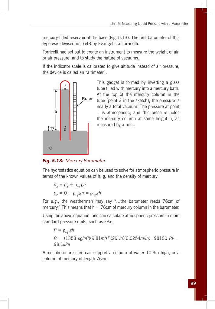
99
Unit 5: Measuring Liquid Pressure with a Manometer
mercury-filled reservoir at the base (Fig. 5.13). The first barometer of this type was devised in 1643 by Evangelista Torricelli.
Torricelli had set out to create an instrument to measure the weight of air, or air pressure, and to study the nature of vacuums.
If the indicator scale is calibrated to give altitude instead of air pressure, the device is called an “altimeter”.
1 2
3
Ruler
Hg
h
This gadget is formed by inverting a glass tube filled with mercury into a mercury bath. At the top of the mercury column in the tube (point 3 in the sketch), the pressure is nearly a total vacuum. The pressure at point 1 is atmospheric, and this pressure holds the mercury column at some height h, as measured by a ruler.
Fig. 5.13: Mercury Barometer
The hydrostatics equation can be used to solve for atmospheric pressure in terms of the known values of h, g, and the density of mercury:
p2 = p3 + ρHg gh
p2 = 0 + ρHg gn = ρHg gh
For e.g., the weatherman may say “…the barometer reads 76cm of mercury.” This means that h = 76cm of mercury column in the barometer.
Using the above equation, one can calculate atmospheric pressure in more standard pressure units, such as kPa:
P = ρHg gh
P = (1358 kg/m3)(9.81m/s2)(29 in)(0.0254m/in)=98100 Pa = 98.1kPa
Atmospheric pressure can support a column of water 10.3m high, or a column of mercury of length 76cm.

100
Physics for Rwanda Secondary Schools Learner’s Book Senior Two
Activity 5.6: Investigating pressure using a u-tube manometer
Take the case of U-Tube manometer in Fig.5.15; discuss and explain the steps in a (Fig.5.15),
b (fig. 5.17), c (fig. 5.18) and d (fig. 5.19) using the rules of the U-tube manometer.
Questions:
1. What does the pressure of liquid in a manometer tube depend on?
2. Discuss other areas where a manometer tube can be used in real life.
The U-tube Manometer caseThis device consists of a glass tube bent into the shape of a “U”, and is used to measure some unknown pressure.
For example, consider the sketch below (Fig. 5.14), where a U-tube manometer is used to measure pressure PA in some kind of tank or machine.
Left Right
Fig. 5.14: The U-Tube manometer
Consider the right side and the left side of the manometer separately. The equation for hydrostatics gives:
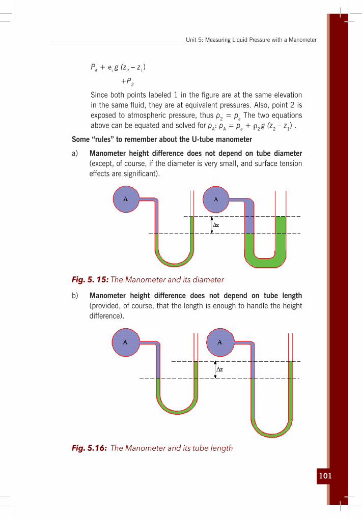
101
Unit 5: Measuring Liquid Pressure with a Manometer
PA + ez g (z2 – z1)
+P2
Since both points labeled 1 in the figure are at the same elevation in the same fluid, they are at equivalent pressures. Also, point 2 is exposed to atmospheric pressure, thus p2 = pa The two equations above can be equated and solved for pA: pA = pa + ρ2 g (z2 – z1) .
Some “rules” to remember about the U-tube manometer
a) Manometer height difference does not depend on tube diameter (except, of course, if the diameter is very small, and surface tension effects are significant).
Fig. 5. 15: The Manometer and its diameter
b) Manometer height difference does not depend on tube length (provided, of course, that the length is enough to handle the height difference).
Fig. 5.16: The Manometer and its tube length

102
Physics for Rwanda Secondary Schools Learner’s Book Senior Two
c) Manometer height difference does not depend on tube shape (except, of course, if the tube is of very small diameter, and surface tension effects are significant).
Fig. 5.17: The Manometer and its shape
Recall that the shape of a container does not matter in hydrostatics. This implies that a U-tube manometer does not have to be in a perfect U shape.
Although the column height difference between the two sides does not change, an inclined manometer has better resolution than does a standard vertical manometer because of the inclined right side. Specifically, for a given ruler resolution, one “tick” mark on the ruler corresponds to a finer gradation of pressure for the inclined case.
d) Manometer height difference does depend on the fluid used in the manometer.
Fig. 5.18: TheManometerandmanometerfluid
For the same pressure difference, a dense manometer liquid will have a smaller difference in column height than a less dense manometer liquid. This too can be used advantageously. If a small pressure difference is being measured, it is better to use a light fluid, since the resolution and accuracy are improved.

103
Unit 5: Measuring Liquid Pressure with a Manometer
Why not always use a very light liquid in a manometer then? Well, for measurement of large pressure differences, the manometer may have to be too high to be practical. In such cases, a very dense liquid, such as mercury, should be used. Furthermore, the manometer liquid must be more dense than the fluid in which the pressure is being measured, for obvious reasons.
5.3.2 Pressure measurement with bourdon gaugesAn aneroid barometer (Bourdon gauges) uses a small, flexible metal box called an aneroid cell. This aneroid capsule (cell) is made from an alloy of beryllium and copper. The box is tightly sealed after some of the air is removed, so that small changes in external air pressure cause the cell to expand or contract. This expansion and contraction drives mechanical levers and other devices which are displayed on the face of the aneroid barometer.
25 25
50
5075
75
100
100
125
125
150 150
0
0
Tubetends to
straightenunder
pressure
Fig. 5.19: Bourdon Gauges A mercury barometer is long and inconvenient, heavy; and contains a liquid that is hazardous and easily split; therefore, an aneroid barometer is commonly used. Aneroid means without liquid. It is compact and portable; it has no liquid to spill and no problem with vapour or air getting in.
5.3.3 Sphygmomanometer Blood pressure is measured in millimeters of mercury (mm Hg). A typical blood pressure is 120/80mm Hg, or "120 over 80." The first number represents the pressure when the heart contracts and is called the systolic blood pressure. The second number represents the pressure when the heart relaxes and is called the diastolic blood pressure.

104
Physics for Rwanda Secondary Schools Learner’s Book Senior Two
Activity 5.7: Measuring blood pressure
Materials:A Sphygmomanometer (blood pressure cuff)
1. Deflate the air bladder of the cuff and place it around the upper arm so it fits snugly. If you’re right handed, you should hold the bulb/pump in your left hand to inflate the cuff. Hold it in the palm so your fingers can easily reach the valve at the top to open and close the outlet to the air bladder.
2. Put the head of the stethoscope just under the edge of the cuff, a little above the crease of the person’s elbow.
3. Inflate the cuff with brisk squeezes of the bulb. Watch the pressure gauge as you do it, you should go to around 150 mmHg or until the pulse is no longer heard. At this point blood flow in the underlying blood vessel is cut off by pressure in the cuff.
290
270
250
230
210
190
170
150
130
110
90
70
50
30
100
20
40
60
80
100
120
140
160
180
200
220
240
260
280
300
Fig. 5.20: The Sphygmomanometer
4. At around 150, slightly open the valve on the air pump (held in your left hand). This part takes practice, it’s important that you don’t let the air out too suddenly.
5. Now, pay attention to what you hear through the stethoscope as the needle on the pressure gauge falls. You will be listening for a slight “blrrp” or something that sounds like a “prrpshh”. The first time you hear this sound; note the reading on the gauge. This value is the systolic blood pressure.
6. The sounds should continue and become louder in intensity. Note the reading when you hear the sound for the last time. This is the diastolic blood pressure.
Questions:1. In your own words, describe how to use a blood pressure cuff
(sphygomomanometer).

105
Unit 5: Measuring Liquid Pressure with a Manometer
5.4 Hare’s apparatus
Activity 5.8: Calculating relative density of a liquid
Observe at the fig. 5.21 below and try to answer the following questions:
A’A
B
B’
hh2
1
liquid water
P
Questions:1. Calculate pressure at B
and B’ due to h1 and h2 respectively.
2. If Pressure at A and A’ are equal, find the relative density of the liquids. ( take density of water to be 1000kg/m3)
Fig. 5. 21. Hare’s apparatus
Finding the Relative Density of Two Liquids Using Hare’s Apparatus
Liquid Liquid
Clip
Bent wirefixed toscale
x cm
h21h
A B
Fig. 5.22: Hare’s apparatus
A vacuum pump is connected to the T- clip and some air is sucked out. The clip is then closed. The pressure inside the glass tubes falls and the

106
Physics for Rwanda Secondary Schools Learner’s Book Senior Two
liquids rise up the tubes. The liquids rise until the pressure due to each liquid column is equal to the difference between atmospheric pressure and the pressure P inside the glass tube. To measure the heights of the liquids h1 and h2 accurately, bend a paperclip into an asymmetric U shape and attach it to the bottom of the ruler. Measure the readings on the ruler respectively.
The pressure at the base of liquid A is then PA = P + ρA gh1
The pressure at the base of liquid B is then PA = P + ρB gh2
Equating these gives P + ρA gh1 = P + ρB gh2
Hence ρA gh1 = ρB gh2 ⇒ PAgh1= ρB gh2 dividing every side of g
eAh1 = eBh2
eA
eB
=
5.5 Unit 5 assessment
1. Find the pressure of that gas sample in Fig 5.17
Air pressure, 101.3 kPa
Valve
a b
105 mm 655 mm
Gassample
Gassample
Fig. 5.23: The Opened and closed tube manometer measures pressure
2. Mercury has a density that is about 14 times greater than that of water. If you were to build a barometer that uses water instead of mercury, how would the height of the column of water needed compare to that of the mercury? a) higher than
b) lower than
c) equal to
d) can’t tell

107
Unit 5: Measuring Liquid Pressure with a Manometer
3. Another barometer is placed next to the one discussed previously. The second barometer uses a wider glass tube but is otherwise the same. The top of the column in the second barometer is the height in the narrow barometer.a) higher than
b) lower than
c) at the same height as
d) don’t know.”
4. A nurse administers medication in a saline solution to a patient by infusion into a vein in the patient’s arm. The density of the solution is 1.0 × 10³kg/m3 and the gauge pressure inside the vein is 2.5 × 10³. How high above the insertion point must the container be hung so that there is sufficient pressure to force the fluid into the patient?
5. A tube in a form of U with uniform section contains mercury. In one of the branches, they pour successively 8cm of water and 6cm of ether. Determine the difference in height between the two free levels; the volume weight of ether is 7115N/m3, that of mercury is 1333 × 102N/m3.
6. In a tube in a form of U, Fig 5.24, they pour mercury. Then in one branch they pour 20cm of water and 20cm of naphtha in the other branch. Calculate the difference in height from the surfaces of separation. Volume weight of naphtha is 6157N/m3.
P
P1
h1
h2
P2
(a) (b)
atmPatm
Fig. 5.24: U-tube manometer 1
7. Determine the pressure difference between points A and B, for the set-up shown in Fig 5.25. Volume weight unit of water is taken as ω = ρg = 9790N/m3.

108
Physics for Rwanda Secondary Schools Learner’s Book Senior Two
Oil d = 0.8
H1 = 0.08
H2 = 0.13
H3 = 0.1 AB
X
Oil d = 0.70
mercury d = 13.6
Fig. 5.25: U-Tube manometer 2
8. In a tube in a form of U, they pour mercury and then water in the other branch. The height of water column is 10cm. What could be the height of oil column that could bring the two levels of mercury into the same horizontal plan? The oil volume weight is .7752 kg/m3
9. Calculate the pressure at a depth of 2m in swimming pool filled with water.
10. Water and oil are poured into the U-shaped tube, fig 5.26, open at both ends, and do not mix. They come to equilibrium as shown in the fig. below. What is the density of the oil?
Oil
Water
a b
27.2 cm9.41 cm
Fig. 5.26: The U-tube manometer 3

Forces

110

111
Unit6
Pascal’s Principle and its Applications
Key unit competenceThe learner should be able to explain transmission of pressure in fluids at rest and describe its applications.
My goalsBy the end of this unit, I will be able to:
explain static pressure of fluids at rest. describe transmission of pressure in static fluids. explain Pascal’s principle. describe applications of Pascal’s principle (Hydraulic press,
Hydraulic brake, Water Towers, Hydraulic jack). Illustrate Pascal’s principle. explain the functioning of hydraulic jack, lift and dump truck,
and car brakes. learn that pressure exerted on an enclosed fluid is equally
transmitted in all directions. understand how pressure transmitted in a fluid produces a
large force when a small force is applied to it.
Key concepts1. What do you understand on Pascal’s Principle?2. Which factors affect the application of Pascal’s principle?3. Discuss transmission of pressure in a hydraulic press.4. Discuss different applications of Pascal’s principle in real life.

112
Physics for Rwanda Secondary Schools Learner’s Book Senior Two
Vocabulary
Hydraulic press, water tower, cylinder, piston,, liquids in equilibrium, cross section area.
y Reading strategy
When you are reading this section, take time to understand what you are reading especially the meaning of key words. This will help you to express them in your own words. You will be able to express your calculations and draw your own experiments about Pascal principle.
6.1 Fluid static and pressure in fluids at rest
Activity 6.1: Investigating the variation of pressure with depth
Materials: Bath Water
Procedures: Pour water in the bath. Let it be in equilibrium for like 5 minutes.
Questions:1. Is that water flowing?2. What is the state of motion that water has?3. How would you find the pressure at the bottom of the bath?
Fluid static (also called hydrostatics) is the science of fluids at rest, and is a sub-field within fluid mechanics. It embraces the study of the conditions under which fluids are at rest in stable equilibrium. The use of fluid to do work is called hydraulics, and the science of fluids in motion is fluid dynamics.
A fluid is defined as a substance that continually deforms (flows) under an applied shear stress (deformation). All gases and liquids are fluids. Fluids are a subset of the phases of matter and include liquids, gases and plasmas.

113
Unit 6: Pascal’s Principle and its Applications
Several properties of fluids need to be established before we concentrate our discussion on Archimedes’ Principle and Pascal’s Principle.
Fluids display such properties as Density which is defined as the ratio of mass per unit volume. It is generally represented by the Greek letter ρ, and measured in terms of kilograms/cubic meter, or kg/m3.
ρ = massvolume
Since the volume of a fluid expands and contracts, the density of fluids varies with temperature. The most common fluid, water, has maximum density of 1000kg/m3 at 4ºC. Air, a mixture composed principally of the gases nitrogen (78%) and oxygen (21%), has a density of 1.29kg/m3 at 0ºC and 1.20kg/m3 at 20ºC.
How a liquid’s density compares to that of water at 4ºC is called its specific gravity. If a liquid has a specific gravity of 0.9, then its density is 0.9 times that of water, or 0.9 x 1000kg/m3 = 900kg/m3.
6.2 Pascal’s principle and its application
In the physical sciences, Pascal’s law or Pascal’s principle (1647) states that: “pressure applied to an enclosed fluid, is transmitted equally to every part of the fluid.”
Activity 6.2: Investigating the variation of pressure with depth
Materials: A clean water bottle (eg: Inyange mineral water bottle) Water A pin
Procedure: Take water in the bottle. Using a pin to make holes on different sides. Pump air in the bottle from its opening.

114
Physics for Rwanda Secondary Schools Learner’s Book Senior Two
Questions:1. Does water fall at the same distances as before?2. Compare the distance of water from the lower part and that
of the upper part of the bottle.3. What causes water to appear to fall at the same distances
while it is being pressed?
Table 6.1: Transmissionofpressureinfluids
Fig. 6.1: Transmission of pressure in liquid
This can be demonstrated using a glass vessel as shown in Fig.6.1. When force is applied to the piston the pressure exerted on the water is transmitted equally throughout the water so that water comes out of all the holes with equal force.
When pressure is applied at a point in a confined fluid, it is transmitted equally in all directions.
Fig. 6.2: Transmission of pressureinfluid
“Any external pressure applied to a fluid is transmitted undiminished throughout the liquid and onto the walls of the containing vessel”
Hydraulic devices like the hydraulic press and car brakes are based on the above principle.
“For all points at the same absolute height in a connected body of an incompressible fluid at rest, the fluid pressure is the same. The difference of pressure due to a difference in elevation within a fluid column is given by: ∆p = ρg∆h”

115
Unit 6: Pascal’s Principle and its Applications
Where, using SI units,
∆P is the hydrostatic pressure (in pascals Pa), or the difference in pressure at two points within a fluid column, due to the weight of the fluid;
ρ is the fluid density (in kilograms per cubic meter kg/m3); g is sea level acceleration due to Earth’s gravity (in meters per
second squared m/s2); ∆h is the height of fluid above (in meters m), or the difference in
elevation between the two points within the fluid column.The intuitive explanation of this formula is that the change in pressure between two elevations is due to the weight of the fluid between the elevations.
Note that the variation with height does not depend on any additional pressures. Therefore Pascal’s law can be interpreted as saying that any change in pressure applied at any given point of the fluid is transmitted undiminished throughout the fluid.
6.2.2 Pascal’s Principle calculationA hydraulic pump is used to lift a car; When a small force F is applied to a small area A of a movable piston it creates a pressure p = F/A. This pressure is transmitted to and acts on a larger movable piston of area A’ which is then used to lift a car.
Area A’
If A’>>A then F’>>F
Area A
FF
A AA’
A’F’F’F P
P P P P P P
F’= = =
Fig. 6.3: The Hydraulic pump
When a force is applied at one end it is transferred to the other end. From the relation: F = p × A
We see that a small force (thrust) applied at the end with a small area will produce a larger force at the end with the larger area: F '= p × A'
Since pressure equals force per unit area, then it follows that FA
= F'A'

116
Physics for Rwanda Secondary Schools Learner’s Book Senior Two
In both cases the volume of the fluid remains the same. So if the small piston moves through a distance h and as a result the large piston moves through a distance h’, then the two volumes replaced by the piston and the fluid must be equal i.e. volume displaced by small piston = volume occupied when large piston moves or V = h × A = h' × A'. This gives the velocity ratio:
VR = hh'
= A'A
So if the area of the large piston is πR2 and that of the small piston is πr2, then
VR = hh'
= A'A
= R 2
r 2
This same principle is also used to produce a great force in a car lift and car transmission systems as well as the hydraulic brake.
For example, if the ratio of the areas is 5, a force of 100N on the small piston will produce a force of 500N on the large piston, and the small piston must be pushed 50cm to get the large piston to rise 10cm. This is how energy, in the form of work in this case, is conserved and the Law of Conservation of Energy is satisfied. Work is force times distance, and since the force is increased on the larger piston, the distance the force is applied over must be decreased. The work of the small piston, 100N multiplied by 0.5m (50cm) is 50 Joules (J), which is the same as the work of the large piston, 500N multiplied by 0.1 m (10cm).
6.2.3 Application
6.2.2.1 Hydraulic pressA hydraulic press is a hydraulic mechanism for applying a large compressive force. It is the hydraulic equivalent of a mechanical lever, and is also known as a Bramah press after the inventor, Joseph Bramah, of England in 1795. Hydraulic presses are the most commonly-used and efficient form of modern press. A fluid, such as oil, is displaced when either piston is pushed inward.

117
Unit 6: Pascal’s Principle and its Applications
Pressure applied to small pistonPressure transmitted by fluid
Small pistonLargepiston
Valve
Valve
BA
Reservoir
Piston
Fig. 6.4: The Hydraulic press
6.2.2.2 Hydraulic brakeThe hydraulic brake is a braking mechanism which uses brake fluid, typically containing ethylene glycol, to transfer pressure from the controlling unit, which is usually near the driver of the vehicle, to the brake cyclinder, which is usually at or near the wheel of the vehicle.
Brake cylinder
attached to wheelDisk,
Brake pads
Pedal
Mastercylinder
The most common arrangement of hydraulic brakes for vehicles consists of a brake pedal, a vacuum assist module, a master cylinder, hydraulic lines, and a brake rotor and/or brake drum.
Fig. 6.5: The Hydraulic brake
At one time, passenger vehicles commonly employed disc brakes on the front wheels and drum brakes on the rear wheels. However, four wheel disc brakes have become more popular, replacing drums on all but the most basic vehicles. As the brake pedal is pressed, leverage multiplies the force applied from the pedal to a vacuum booster. The booster multiplies the force again and acts upon a piston in the master cylinder.

118
Physics for Rwanda Secondary Schools Learner’s Book Senior Two
As force is applied to this piston, pressure in the hydraulic system increases forcing fluid through the lines to the slave cylinders. The slave cylinders for a drum brake are a pair of opposed pistons which are forced apart by the fluid pressure, while for a disc brake a single piston is forced out of its housing.
The slave cylinder pistons then apply force to the brake linings, which are referred to as shoes in the case of drum brakes or as pads in the case of disc brakes. The forces applied to the linings cause them to be pushed against the rotating metal of the drum or rotor. The friction between the linings and the metal causes a braking torque to be generated, slowing the vehicle.
Hydraulicbrake fluid
Piston which controls the leversSpring to release brakesBrake shoeBrake liningBrake drum which is rigid attached to the wheel of the car
Piston
Mastercylinder
Foot brake
Fig. 6.6: The hydraulic brake
The fluid pressure from the master cylinder is transferred equally to all the brake shoes.
6.2.2.3 Water TowersA water tower or elevated water tower is a large elevated water storage container constructed for the purpose of holding a water supply at a height sufficient to pressurise a water distribution system.
Pressurisation occurs through the elevation of water; for every 10.20cm of elevation, it produces 1 kilopascal of pressure. 30m of elevation produces roughly 300 kPa, which is enough pressure to operate and provide for most domestic water pressure and distribution system requirement.

119
Unit 6: Pascal’s Principle and its Applications
6.2.2.4 Hydraulic lift car
A1A2
F2
F1
2x∆1
x∆
Fig. 6.7: The hydraulic lift.
Because the increase in pressure is the same on the two sides, a small force Fl at the left produces a much greater force F2 at the right. A vehicle undergoing repair is supported by a hydraulic lift in a garage.
6.3 Hydrostatic paradox
Activity 6.3: Investigating the hydraulic pressure
Take the case of Fig. 6.8; read and then discuss and explain what you have realised from case A (Fig. 6.9) up to case E (Fig 6.13).
If the height of the fluid’s surface above the bottom of the five vessels is the same, in which vessel is the pressure of the fluid on the bottom of the vessel the greatest? The amount of liquid in each vessel is not necessarily the same.
P P P P P P
A B C D E
Fig. 6.8: The Hydrostatic Paradox: The pressure, p is the same on the bottom of each vessel.

120
Physics for Rwanda Secondary Schools Learner’s Book Senior Two
Why the pressure does not depend upon the shape of the vessel or the amount of fluid in the vessel but rests upon three things below:
1. Pressure is force per unit area and this is not the same as the total weight of the liquid in a vessel.
2. A fluid cannot support itself without a container. Thus the walls of the container exert a pressure on the fluid equal to the pressure of the fluid at that depth.
3. The pressure at a given level is transmitted equally throughout the fluid to be the same value at that level.
ExplanationsTable 6.2: Explanation of the Hydrostatic Paradox
Vessel A: No matter how wide the vessel, the pressure is just the weight of the fluid above unit area on the bottom. Even if you take the whole weight of the fluid in the container mg and divide by the area of the bottom A, you still get the same results since the vessel is equivalent to a column of water.
p = mgA
= ρVgA
= ρ(Ah)gA
= ρghP
A
P
AreaA
V = Ahh
Fig. 6.9: Vessel AVessel B: Vessel B could be divided into three parts. The fluid in parts 1 and 3 is supported by upward force of the vessel on the fluid. Part 2 could be thought of a vertical column of liquid similar to vessel A.
One could ask; why doesn’t the fluid in parts 1 and 3 (which are much bigger) not squeeze column 2 where they meet (along the dashed line) and thereby increase the pressure on the bottom of the column? The answer is that the fluid in column 2 exerts pressure and is equal but opposite pressure outwards on the two other liquids to support itself. From the point of view of column 2, the water outside the dashed lines in sections 1 & 3 could be replaced by solid vertical walls (along the dashed lines) and column 2 would still be in equilibrium.
B
2
1 3
Fig. 6.10: Vessel B

121
Unit 6: Pascal’s Principle and its Applications
Vessel C: Again we could divide the water into three sections. The middle section is similar to that of vessel A or B. Since the height of the fluid in section 1 or 3 is not high enough to produce the same pressure as the height of the fluid in 2, how does the pressure on the bottoms of section 1 and 3 get to be the same as that of 2? The answer is that top of the container’s walls in sections 1 and 3 produce a downward pressure that is equal to the fluid pressure in the middle section at the same level. If you poked a hole in the top of the container in sections 1 or 3, water would fountain upwards from the hole under pressure. From Pascal’s principle, this pressure has to be that of the fluid in the middle section at the same level.
C
P P P
2 31
Fig. 6.11: Vessel C
Description of hydrostatic paradox
Vessel D: Again the center column is similar to vessel A.
The pressure of the vessel’s wall creates a pressure that vertically supports the fluid in sections 1 and 3. At the same time the pressure of the walls create a horizontal component of pressure that sustains the fluid in the center column.
Diagrams of the hydrostatic paradox
P
D
1 2 3
Fig. 6.12: Vessel DVessel E: While one cannot offer simple arguments like those for the other vessels, the pressure on the bottom is still the same basically because of Pascal’s principle.
You go down from the surface to some depth, and then move sideways until you can go down again. Repeat the process until you reach the bottom. Since the pressure at the same depth is the same, moving sideways does not change the pressure. Only downwards motion increases the pressure.
E
h
h1
h2
h3
1 2 3
1 2 3( )P gh gh ghh h h hgh
ρ ρ ρρρ
= + += + +=
Fig. 6.13: Vessel E

122
Physics for Rwanda Secondary Schools Learner’s Book Senior Two
At a depth of 10 meters under water, pressure is twice the atmospheric pressure at sea level, and increases by about 105 kPa for each increase of 10m depth.
6.4 Unit 6 assessment
1. The maximum gauge pressure in a hydraulic lift is 18 atm. What largest mass vehicle can it lift if the diameter of the output line is 22cm?
2. Pascal placed a long tube with a radius of 0.30cm into a barrel (Fig 6.8) with a 20.0cm radius top. When the water was filled to the 12.0m height the barrel burst.
r = 0.30 cm
R = 21 cm
12 m
a) Calculate the mass of water in the tube.
b) Calculate the net force on the lid.
3. What is the total pressure on a diver 45.0m below the sea?
Fig. 6.14: Barrel
4. The master cylinder of a brake system has a radius of 0.100cm and the cylinders at the brake pads have radii of 4.00cm. If Debi can apply a force of 150N on the brake pedal, what is the force applied to slow down her car?
5. Find the pressure needed to push water to the top of the Tower, a height of 8.0m (use mass units), the density of water is 1.0 g/cm3.
6. Find the total force on the filled school dam whose dimensions are 5.0m by 2.0m. The average depth is 1.0m.
7. Calculate the pressure and density of air at an elevation of 5000m above mean sea level. The atmospheric pressure and temperature at sea level are 101.35 KPa and 15oC respectively. The temperature lapse rate is 0.007 K/m. The density of air at sea level is 1.2255 kg/m3.

123
Unit 6: Pascal’s Principle and its Applications
8. Rank the pressures at the three points of the figure below:
A
B C
a) pA < pB = pC
b) pA < pB < pC
c) pA < pC < pB
d) pC < pA < pB
9. Three containers of different shape, but with bases of equal area (Fig 6.9) are filled with water to the same height.
A B C
Fig. 6.15: Containers
a) The weight of the water is the greatest in container…
(i) A
(ii) B
(iii) C
(iv) The weight of the water is the same in all the three containers.
b) The pressure at the bottom of the container is the greatest in container…
(i) A
(ii) B
(iii) C
(iv) The pressure at the bottom is the same in all the three containers
10. Calculate the pressure due to water column of height 100m (Take g = 10 m s-2 and density of water = 103 kg m-3). What height of mercury column will exert the same pressure? (Density of mercury = 13.6 x 10³ kg m-3)
11. What is the pressure due to water pressure 100m below the surface of a lake?
12. Figure 6.16 shows a hydraulic weight bridge which works on the principle of Pascal’s law.

124
Physics for Rwanda Secondary Schools Learner’s Book Senior Two
1600cm216 cm2B A
8kg
Piston
Fig. 6.16: The Hydraulic press
a) What is the pressure at B?
b) What is the pressure at A?
c) What is the weight of the vegetable on the large piston A if the weight bridge is in equilibrium?
13. A regularly shaped object is immersed in water of density 1000 kgm-3 (Fig 6.17)
0.15 m0.10 m Water
Object
Fig. 6.17: Pressure exerted on a body in water
a) Calculate the water pressure at the top and the bottom of the object.
b) What is the resultant pressure on the object?

Pressure

126

127
Unit7
Archimedes’ Principle and Atmospheric Pressure
Key unit competenceThe learner should be able to determine atmospheric pressure using a Barometer.
My goalsBy the end of this unit, I will be able to:
explain atmospheric pressure and state its units. explain applications of atmospheric pressure. illustrate Archimedes principle in air. explain buoyant/up thrust force and Archimedes principle in
liquid. explain the existence of atmospheric pressure. state the S.I. units of atmospheric pressure. identify and name the instruments for measuring atmospheric
pressure. mention and explain the applications of atmospheric pressure. explain the Archimedes principle in fluids: up thrust, factors
affecting up thrust, state the principle and formula. apply the Archimedes principle: floating and sinking. explain the applications of Archimedes principle in air. (Aerostat,
Baroscope)

128
Physics for Rwanda Secondary Schools Learner’s Book Senior Two
Key concepts1. How to detect the existence of atmospheric pressure in our
environment?2. What is atmospheric pressure?3. What do we use to measure atmospheric pressure?4. Explain the key concept of buoyancy and up-thrust.5. Discuss Archimedes’ principle in fluids (liquids and gases).6. Discuss different applications of Archimedes principle in fluids
in real life.
Vocabulary
Barometer, up-thrust force, floating, sinking, aerostat, atmospheric pressure, buoyancy.
y Reading strategy
When reading this unit, emphasise the paragraphs that contain definitions of key terms. Use all the information you have learnt to define each key term in your own words, describe and discuss Archimedes principle and its application in real life and other related calculations.
7.1 Atmospheric pressure
7.1.1 Existence of atmospheric pressureThe existence of the atmospheric pressure can be proved by the following experiments.
1. Crushing can experiment.2. Overturned glass full of water3. Magdeburg Hemisphere.
Activity 7.1: Crushing can experiment
With reference to the Fig. 7.1, and the provided materials, do the following activity and answer the questions.
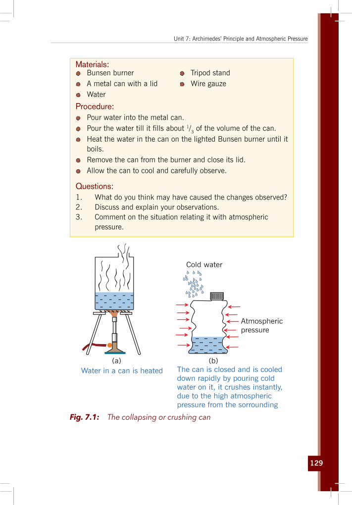
129
Unit 7: Archimedes’ Principle and Atmospheric Pressure
Materials: Bunsen burner A metal can with a lid Water
Tripod stand Wire gauze
Procedure: Pour water into the metal can. Pour the water till it fills about 1/3 of the volume of the can. Heat the water in the can on the lighted Bunsen burner until it
boils. Remove the can from the burner and close its lid. Allow the can to cool and carefully observe.
Questions:1. What do you think may have caused the changes observed?2. Discuss and explain your observations.3. Comment on the situation relating it with atmospheric
pressure.
Water in a can is heated
Atmosphericpressure
Cold water
(a) (b)The can is closed and is cooleddown rapidly by pouring coldwater on it, it crushes instantly,due to the high atmosphericpressure from the sorrounding
xxxxxxxx
Fig. 7.1: The collapsing or crushing can
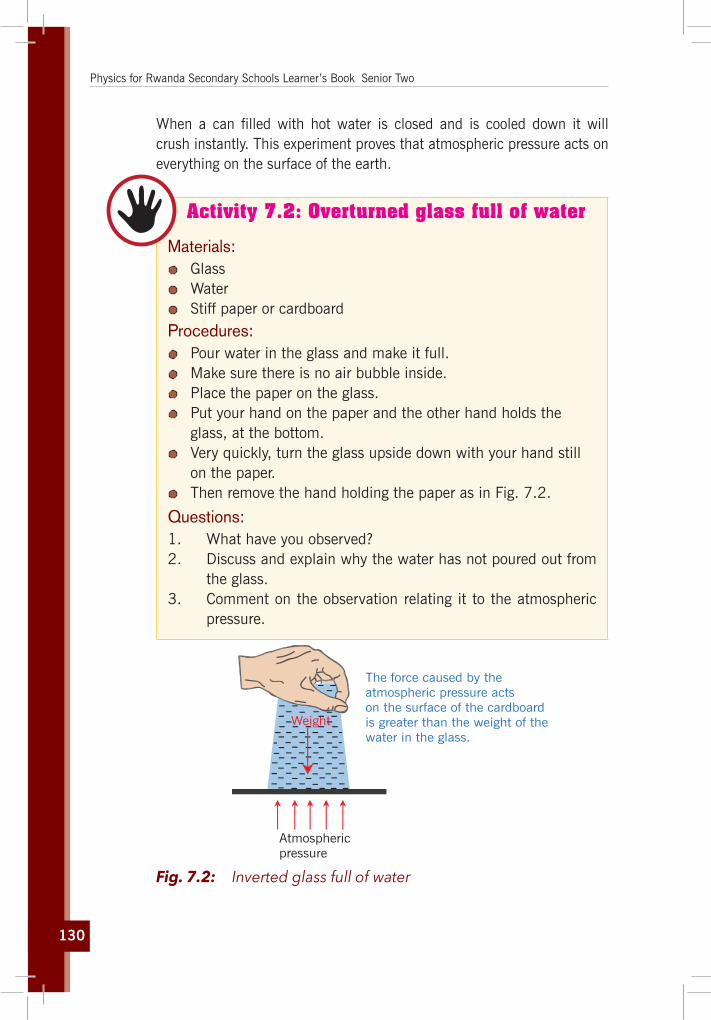
130
Physics for Rwanda Secondary Schools Learner’s Book Senior Two
When a can filled with hot water is closed and is cooled down it will crush instantly. This experiment proves that atmospheric pressure acts on everything on the surface of the earth.
Activity 7.2: Overturned glass full of water
Materials: Glass Water Stiff paper or cardboard
Procedures: Pour water in the glass and make it full. Make sure there is no air bubble inside. Place the paper on the glass. Put your hand on the paper and the other hand holds the
glass, at the bottom. Very quickly, turn the glass upside down with your hand still
on the paper. Then remove the hand holding the paper as in Fig. 7.2.
Questions:1. What have you observed?2. Discuss and explain why the water has not poured out from
the glass.3. Comment on the observation relating it to the atmospheric
pressure.
Atmosphericpressure
Weight
The force caused by theatmospheric pressure actson the surface of the cardboardis greater than the weight of thewater in the glass.
Fig. 7.2: Inverted glass full of water
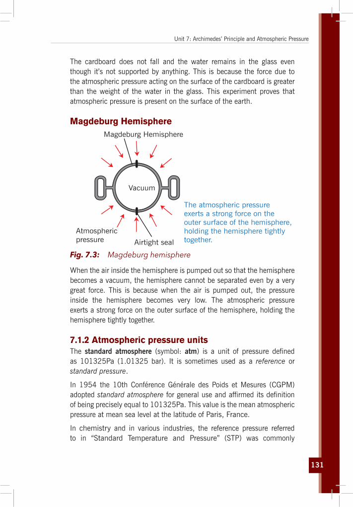
131
Unit 7: Archimedes’ Principle and Atmospheric Pressure
The cardboard does not fall and the water remains in the glass even though it’s not supported by anything. This is because the force due to the atmospheric pressure acting on the surface of the cardboard is greater than the weight of the water in the glass. This experiment proves that atmospheric pressure is present on the surface of the earth.
Magdeburg HemisphereMagdeburg Hemisphere
Vacuum
Atmosphericpressure Airtight seal
The atmospheric pressureexerts a strong force on theouter surface of the hemisphere,holding the hemisphere tightlytogether.
Fig. 7.3: Magdeburg hemisphere
When the air inside the hemisphere is pumped out so that the hemisphere becomes a vacuum, the hemisphere cannot be separated even by a very great force. This is because when the air is pumped out, the pressure inside the hemisphere becomes very low. The atmospheric pressure exerts a strong force on the outer surface of the hemisphere, holding the hemisphere tightly together.
7.1.2 Atmospheric pressure unitsThe standard atmosphere (symbol: atm) is a unit of pressure defined as 101325Pa (1.01325 bar). It is sometimes used as a reference or standard pressure.
In 1954 the 10th Conférence Générale des Poids et Mesures (CGPM) adopted standard atmosphere for general use and affirmed its definition of being precisely equal to 101325Pa. This value is the mean atmospheric pressure at mean sea level at the latitude of Paris, France.
In chemistry and in various industries, the reference pressure referred to in “Standard Temperature and Pressure” (STP) was commonly

132
Physics for Rwanda Secondary Schools Learner’s Book Senior Two
1 atm (101.325kPa) but standards have since diverged; in 1982, the International Union of Pure and Applied Chemistry (IUPAC) recommended that for the purposes of specifying the physical properties of substances, “standard pressure” should be precisely 100kPa (1 bar).
Pressure units and equivalenciesTable 7.1: Atmospheric pressure unit conversion
Pascal Bar Standard atmosphere Torr
(Pa) (bar) (atm) (Torr)
1 Pa ≡ 1 N/m2 10−5 9.8692×10⁻⁶ 7.5006×10⁻³
1 bar 105 ≡ 100 kPa
≡ 106 dyn/cm2
0.98692 750.06
1 atm 1.01325×10⁵ 1.01325 1 ≡ 760
1 Torr 133.3224 1.333224×10⁻³ ≡ 1/760
≈ 1.315789×10⁻³
≡ 1 Torr
≈ 1 mmHg
A pressure of 1 atm can also be stated as:
≡ 1.01325 bar
≡ 101325 pascal (Pa) or 101.325 kilopascal (kPa)
≡ 1013.25 millibars (mbar, also mb)
≡ 760 torr[
≈ 760.001 mm-Hg, 0°C, subject to revision as more precise measurements of mercury’s density become available
≈ 1033.227 452 799 886 cm–H2O, 4°C
7.1.3 Instruments for measuring atmospheric pressure 1. Mercury Barometer
A mercury barometer consists of a thick-walled glass tube, which is closed at one end.

133
Unit 7: Archimedes’ Principle and Atmospheric Pressure
Vacuum
Glass tube
Mercurycolumn
Height76 cm (29.92 in.)
Air Pressure
Mercuryin dish
Air Pressure
Fig. 7.4: The Mercury barometer
The tube is completely filled with mercury and inverted several times to remove air bubbles. The tube is then completely filled again with mercury. After all the air has been removed, the open end of the glass tube is inverted into a container of mercury. The mercury column drops until it reaches a height about 76cm above the lower surface. The space between the top of the mercury and the end of the tube contains no air; it is a complete vacuum. The column of mercury in the tube is supported by the atmospheric pressure and its height depends on the magnitude of the atmospheric pressure.
2. Fortin BarometerA fortin barometer is a type of mercury barometer which has a higher accuracy. This barometer has a vernier scale which gives a more accurate reading of the atmospheric pressure. The mercury level in the container can be adjusted by a screw until the pointer touches the surface of the mercury. This eliminates the zero error.

134
Physics for Rwanda Secondary Schools Learner’s Book Senior Two
GlassIvory pointer
MercuryBrass tube
Main scaleVernier
Scale
Screw to adjust vernier
Barometer tube
Leather bag
Screw to adjust mercury level
Fig. 7.5: The Fortin Barometer
3. Aneroid BarometerAn aneroid barometer does not use any liquid. It consists of a sealed metal chamber in the form of a flat cylinder with flexible walls. The chamber is partially evacuated and a spring helps prevent it from collapsing.
The chamber expands and contracts in response to changes in atmospheric pressure. The movement of the chamber walls is transmitted by a mechanical lever system which moves a pointer over a calibrated scale.
Fig. 7.6: The Aneroid barometer

135
Unit 7: Archimedes’ Principle and Atmospheric Pressure
The Aneroid Barometer can be used as an altimeter (to determine altitude) by mountaineers or pilots to determine an airplane’s altitude. The scale can be calibrated to give readings of altitude equivalent to a range of values of atmospheric pressure.
An aneroid barometer is also used as a weather glass to forecast the weather. Rain clouds form in large areas of lower pressure air, so a fall in the barometer reading often means that bad weather is coming.
7.1.4 Application of atmospheric pressure
Drinking Straw
Activity 7.3: Effect of atmospheric pressure when using a drinking straw
With reference to activity 4.4 in unit 4, discuss and explain how atmospheric pressure is applied when drinking using a straw.
When drinking with a straw, one has to suck the straw. This causes the pressure in the straw to decrease. The external atmospheric pressure, which is greater, will then act on the surface of the water in the glass, causing it to rise through the straw.
Rubber Sucker
Activity 7.4: Investigating the atmospheric pressure with a rubber sucker
Materials: Rubber sucker Window glass or a telephone
Procedure: Lay the rubber sucker on the window glass and push slightly. Lay the rubber sucker on the screen or the back part of the
telephone as shown in Fig 7.7 and try to pull it back.
Question:Discuss and explain why the rubber sucker is sticking on the window glass or on the telephone’s screen.
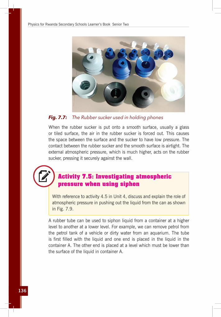
136
Physics for Rwanda Secondary Schools Learner’s Book Senior Two
Fig. 7.7: The Rubber sucker used in holding phones
When the rubber sucker is put onto a smooth surface, usually a glass or tiled surface, the air in the rubber sucker is forced out. This causes the space between the surface and the sucker to have low pressure. The contact between the rubber sucker and the smooth surface is airtight. The external atmospheric pressure, which is much higher, acts on the rubber sucker, pressing it securely against the wall.
Activity 7.5: Investigating atmospheric pressure when using siphon
With reference to activity 4.5 in Unit 4, discuss and explain the role of atmospheric pressure in pushing out the liquid from the can as shown in Fig. 7.9.
A rubber tube can be used to siphon liquid from a container at a higher level to another at a lower level. For example, we can remove petrol from the petrol tank of a vehicle or dirty water from an aquarium. The tube is first filled with the liquid and one end is placed in the liquid in the container A. The other end is placed at a level which must be lower than the surface of the liquid in container A.

137
Unit 7: Archimedes’ Principle and Atmospheric Pressure
Prime until past the fluid level
Move Syphonin quick strokes upand down
Fig. 7.8: Siphoning water from a jerrycan
The pressure in the rubber at the lower end is equal to atmospheric pressure plus the pressure due to h cm column of liquid. As the pressure at the lower end is greater than the atmospheric pressure, the liquid flows out.
Fig. 7.9: A Vacuum cleaner A Lab lift pump

138
Physics for Rwanda Secondary Schools Learner’s Book Senior Two
Activity 7.6: Try this in groups. Application of pressure of liquid in using a lift pump
Materials: Lab lift pump Bucket Water
Procedure: Take water in the bucket. Try to fetch water from the bucket using the lab lift pump in
Fig. 7.10
Questions:1. Discuss and explain the principle function of the lift pump
used above.2. Where can this be applied to help the society?
(a) Downstroke (b) Upstroke
Water level
Atmosphericpressure
Down
H H
AA
B B
Up
Fig. 7.10: A Lift pump sucking water from a well
139
Unit 7: Archimedes’ Principle and Atmospheric Pressure
A lift pump is used to pump water out of a well or to a higher level. The greatest height to which the water can be pumped is 10m. This is equivalent to the atmospheric pressure. When the plunger is lifted, the upper valve closes and the lower valve opens. The atmospheric pressure, acting on the surface of the water, causes water to flow past valve B into the cylinder. When the plunger is pushed down, the lower valve closes and the upper valve opens. Water flows above the plunger. When the plunger is next lifted, the upper valve closes again and the lower valve opens once more. The atmospheric pressure, acting on the surface of the water, forces water past the lower valve into the cylinder. Simultaneously, the water above the plunger is lifted and flows out through the spout. This process is repeated until sufficient water is obtained.
Quick exercise 1. Explain how rubber suckers could be used to help lift panes
of glass safely.2. If one of the windows in a plane flying at high altitude breaks,
what do you think will happen?3. Water has a lower density than mercury. Is the column of
liquid in a mercury barometer taller or shorter than one in a barometer using water?
4. If the density of water is 1000 kg/m3 and atmospheric pressure is 100,000 Pa; how high will the column of water in a perfect water barometer be? (Take g for the Earth as 10 N/kg).
5. What would happen to the mercury level in a mercury barometer if:(a) The atmospheric pressure went down(b) The atmospheric pressure went up(c) A little air leaked into the tube above the mercury(d) The barometer was taken up a high mountain(e) The temperature of the room where the barometer was,
got higher.
[Remember that mercury is a dangerous substance. It should not be used by learners and you should certainly not heat it].
6. Find out what is meant by:(a) a millibar(b) an isobar(c) an anticyclone
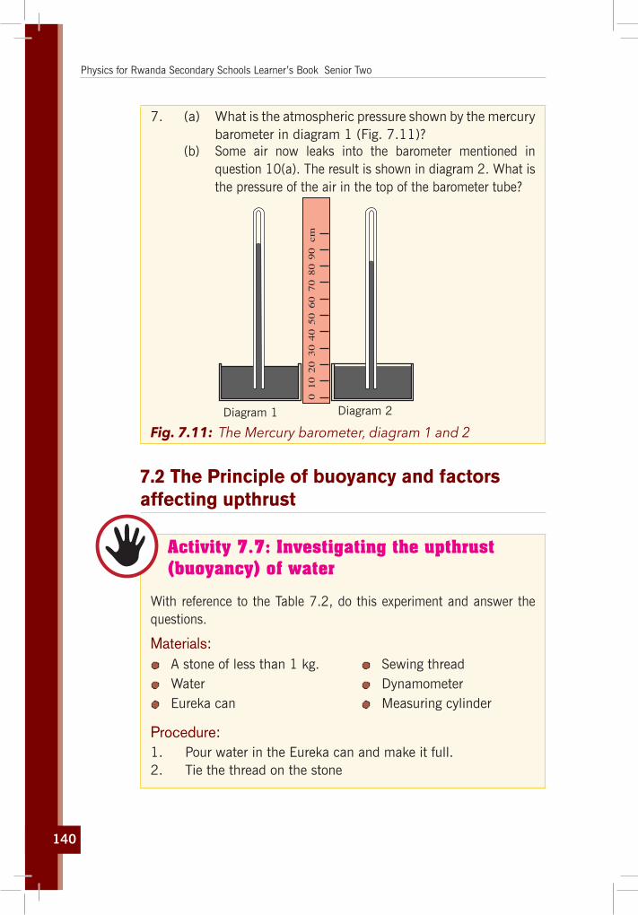
140
Physics for Rwanda Secondary Schools Learner’s Book Senior Two
7. (a) What is the atmospheric pressure shown by the mercury barometer in diagram 1 (Fig. 7.11)?
(b) Some air now leaks into the barometer mentioned in question 10(a). The result is shown in diagram 2. What is the pressure of the air in the top of the barometer tube?
010
20
30
40
50
60
70
80
90
cm
Diagram 1 Diagram 2
Fig. 7.11: The Mercury barometer, diagram 1 and 2
7.2 The Principle of buoyancy and factors affecting upthrust
Activity 7.7: Investigating the upthrust (buoyancy) of water
With reference to the Table 7.2, do this experiment and answer the questions.
Materials: A stone of less than 1 kg. Water Eureka can
Sewing thread Dynamometer Measuring cylinder
Procedure:1. Pour water in the Eureka can and make it full.2. Tie the thread on the stone

141
Unit 7: Archimedes’ Principle and Atmospheric Pressure
3. Measure its weight in air using the dynamometer and record it to be w1
4. Submerge the stone in water still on the dynamometer and record the new weight w2
5. Measure the weight of water overflown in the measuring cylinder and record it as w3
6. Find the difference w' = w1 – w2
Questions:1. Compare the results obtained from step 5 and 6.2. What is the volume of the stone?3. Discuss and explain your findings in question 1.
If you walk in water you feel water pushing your legs up. If you lift a bucket of water from a tank, the bucket appears to be lighter inside the water and suddenly heavy when it comes out of water. A weather forecasting balloon floats in air with its heavy equipment! A ship made of steel floats while a steel pin sinks in water! These experiences are based on Archimedes’ Principle.
An object weighs less in water than it does in the air. This loss of weight is due to the upthrust of the water acting upon it and is equal to the weight of the liquid displaced.
Because salt water is denser than pure water the object displaces a greater weight of salt water and, therefore, weighs less.
The denser the liquid, the easier it is to float in it making it easier to swim in the ocean or a chemical filled pool than a mountain stream
Table 7.2: Archimedes principle of buoyancyObject weighed in air is (say) 640g.
Object weighed in water is (say) 410g.
Object weighed in salt water is (say) 400g.
010
20
30
40
506070
80
90
110
120
100
010
20
30
40
506070
80
90
110
120
100
010
20
30
40
506070
80
90
110
120
100
A minimal weight of air is displaced.
010
20
30
40
506070
80
90
110
120
100
010
20
30
40
506070
80
90
110
120
100
010
20
30
40
506070
80
90
110
120
100
Weight of water displaced is 230 g.
010
20
30
40
506070
80
90
110
120
100
010
20
30
40
506070
80
90
110
120
100
010
20
30
40
506070
80
90
110
120
100
Weight of salt water displaced is 240 g.

142
Physics for Rwanda Secondary Schools Learner’s Book Senior Two
Buoyancy reduces the apparent weight of objects that have sunk completely to the sea floor. It is generally easier to lift an object up through the water than it is to pull it out of the water. In the case of a submerged body, the apparent weight of the body is equal to its weight in air less the weight of an equal volume of fluid and the object that floats will displace a volume of water equal to its weight:
According to Archimedes’ principle,
“Any object that is completely or partially submerged in a fluid at rest is acted on by an upward (or buoyant) force. The magnitude of this force is equal to the weight of the fluid displaced by the object and the volume of fluid displaced is equal to the volume of the portion of the object submerged.”
B = Wf = mf g = ρf gV displaced
Fig. 7.12: Force acting on a submerged body
Thus, among completely submerged objects with equal masses, objects with greater volume have greater buoyancy. The horizontal forces on its vertical sides cancel and are removed from consideration.
The upward forces against the bottom surface of the object are greater than the downward forces against its top surface. This net force is called the buoyant force. In other words the “buoyant force” on a submerged body is directed in the opposite direction to gravity and is equal in magnitude. The net force on the object is thus the sum of the buoyant force and the object’s weight:
F = W + B If the buoyancy of an object exceeds its weight, it tends to rise.
F = B – W
An object whose weight exceeds its buoyancy tends to sink.F = W – B

143
Unit 7: Archimedes’ Principle and Atmospheric Pressure
Commonly, the object in question is floating in equilibrium and the sum of the forces on the object is zero, therefore; F = W – B = 0
T 1T 2
W = mg
m mW
B
Fig. 7.13: Forces on a suspended body. “Loss of weight” in a liquid
You probably noticed that all of the methods employing Archimedes’ principle with a balance scale required the subtraction of two scale readings. Balances compare forces (weights), but their scales read mass units (grams). From Fig 7.13 we find that:
Suspended in air: T1 = mg
Suspended in liquid: T2 + B = mg
Therefore, T1 – T2 = B
But Archimedes’ principle tells us that: B = ρf Vg where ρf is the density of the liquid. T1 – T2 = ρf Vg
T1
T1 – T2
= ρVgρf Vg
⇔ T1
T1 – T2
= ρρf
= ef is density of any fluid.
7.2.2 Application
7.2.2.1 Archimedes’ principle and density
Activity 7.8: Investigating the floating condition
Materials:Observe Fig.7.14 and then try to answer the questions below:
1. Compare the three cases and describe each case.2. Comment on the situation relating with the pressure in
liquids.

144
Physics for Rwanda Secondary Schools Learner’s Book Senior Two
We use density in the determination of whether a substance will float or sink in another substance usually a liquid or gas. If the buoyancy of an object exceeds its weight, it tends to rise. An object whose weight exceeds its buoyancy tends to sink. Commonly, the object in question is floating in equilibrium and the sum of the forces on the object is zero. When a non-porous object is placed in a fluid, there are three possible outcomes:
>
Case 1 Case 2 Case 3
W1 W2W2W1
W2
W1
W1 W2W1
=
Fig. 7.14: The Density and Floating condition
Case 1: Neutral buoyancyA material or object having the same density as a liquid will remain submerged in the liquid, neither floating to the top nor sinking to the bottom.
If ρb = ρf then F = W – B ⇔ F = ρb gV – ρf gV ⇔ F = (ρb – ρf ) gV = 0 the object has neutral buoyancy (neither rising nor falling).
Case 2: Sinker objectThe object sinks when the density of the object is greater than the density of the displaced fluid. For an object that sinks, the volume of displaced water equals the volume of the object i.e. if ρb > ρf then
F = W – B ⇔ F = ρb gV – ρf gV ⇔ F = (ρb – ρf ) gV > 0.
Suppose a body has a density ρ and a mass M. The volume of the body is
V = Mρ
and its weight in air is Mg.
The apparent weight of the body when immersed in a liquid of density ρf is, by Archimedes’ principle ML g = Mg – Vρf g. Thus ML = M – Vρf
Replacing V by Me we get:
ML = M – Me ef
=M (1– ef
e

145
Unit 7: Archimedes’ Principle and Atmospheric Pressure
Since ML and M may be measured by a balance, it follows that if the density ρf of the liquid- say water- is known, the density ρ of the body may
be calculated from ρ = Mρf
M – ML
That equation states that the “density of object = (weight of object divided by loss of weight when submerged in fluid) × density of the fluid”
ρ
ρf
= MM – ML
i.e density of objectdensity of fluid
= weightweight – apparent immersed weight
The relative densities of solids
Relative density or specific gravity = weight of object/weight of equal volume of water:
S.G. = ρρW
= M
(M – ML)
Example: When a crown of mass 14.7kg is submerged in water, an accurate scale reads only 13.4kg. Is the crown made of gold (density of gold is) 19,300 kg/m3?
Answer:The specific gravity ( S.G) of that crown is;
SG = ρS = Ma eW
Ma – MW
= 14.7 × 100014.7 – 13.4
= 11300 kg/m3
The crown seems to be made of lead (11300 kg/m3) not made of gold.
7.2.3 Relative density of liquidsUsing the same procedure as in the previous experiment, a sinker is weighted first in air, then in liquid, and finally in water. The sinker is any convenient solid body. Since the same sinker is used in both liquids, the two apparent losses in weight will be the weight of equal volumes of liquid and water respectively.
Therefore, the density of the sinker:
Using the equation eef
= Ma
Ma – Mf
The density of the sinker is given by:
(i) in the liquid equation (a) = equation (b)
es =
Ma ef
Ma – Mf (a) es =
Ma ef
Ma – Mf
= Ma ew
Ma – Mw

146
Physics for Rwanda Secondary Schools Learner’s Book Senior Two
(ii) in water es
Ma ew
Ma – Mw (b)
ef
Ma – Mf
= ef
Ma – Mw
and so
efew
=
Ma Mf
Ma – Mw
In terms of weights efew
= Wa Wf
Ma – Mw
i.e. Relative Density (R.D) of a liquid: RD = loss of weight of sinker in liquidloss of weight of sinker in water
Case 3: Objects that float
M’
M 1
M
Lg
Fig. 7.15: BlockofwoodimmersedinfluidbysinkerM1
Density of the solid is less than the density of the liquid and hence the object will float or, in the case of a balloon, it will rise i.e. If ρb < ρf then
F = W – B where W is the weight of the body and B is the upthrust.
F = ρb gV – ρf gV'
A body will float if F = 0 i.e. ρb
ρf
= V'V
This equation tells us that the fraction of the volume of a floating object that is below the fluid surface is equal to the ratio of the density of the object to that of the fluid.
Under normal conditions, the weight of a fish is slightly greater than the buoyant force due to water. It follows that the fish would sink if it did not have some mechanism for adjusting the buoyant force. The fish accomplishes this by internally regulating the size of its air-filled swim bladder to increase its volume and the magnitude of the buoyant force acting on it. In this manner, fish are able to swim to various depths.
For a floating object the mass of displaced water equals the mass of the object. Law of flotation

147
Unit 7: Archimedes’ Principle and Atmospheric Pressure
A body will rise if V = V’ If the body whose density is to be measured is less dense than the liquid, it is necessary to fasten the body to a sinker so that the two together sink in the liquid. Let M1 be the mass in air of the body, say a block of wood, whose density ρ1 is less than that of the liquid whose density is ρf. Suppose the body of mass M1, density ρ1, referred to above, is such that when fastened to the sinker the two together sink in the liquid. Let the weight of the two together when completely immersed in the liquid be M'L g. Then from Fig. 7.15 it is readily seen that:
The upthrust in a fluid is given by:
M – Mf Mef
eUpthrust on the sinker
u1 = Mew
es
upthrust on the block of wood u2 = M1ew
e1
M'L g = Mg + M1 g – Mgρf
ρ – M1 gρf
ρ1
or M'L = ML + M1 – M1 ρf
ρ1
If the sinker has a very small volume but very dense, then Mef
e will be very
small and negligible hence:
M'L = ML + M1– M1ef
e1
Hence ρ1 = M1 ρf
ML + M1 – ML'A liquid will float on another liquid, and a solid will float in a liquid, if it is less dense than the liquid.
Example: A ship of mass 1200t floats in sea-water. What volume of sea-water does it displace? If the ship enters fresh water, what mass of cargo must be unloaded so that the same volume of water is displaced as before? (Density of fresh water = 1000kg/m3, relative density of sea-water = 1.03 and 1 t = 1000kg).
Answer:The ship displaces a weight of sea-water equal to its own weight and therefore a mass of sea-water is equal to its own mass.
Mass of sea-water displaced: md = 1200t = 1,200,000kg

148
Physics for Rwanda Secondary Schools Learner’s Book Senior Two
Density of sea-water: ρS = RD × ρW = 1.03 × 1000kg/m3 = 1030 kg/m3
Volume displaced: Vd = mρ
= 1,200,0001030
= 1165m3 of sea-water
The same volume of fresh water has a mass of mf = Vd× ρf = 1165000kg
Therefore, mass of cargo to be unloaded: mu = 1200000kg – 1165000kg = 35000kg
7.2.2.2. Submarines
(i) Surface
Water
Keel
Ballast tanks Canning tower
(ii) Diving trim (iii) Submerged
Fig. 7.16: A Submarine
A submarine (the word submarine was originally an adjective meaning “under the sea”) is made to float or sink by altering the average density. By average density is meant the value obtained by dividing the total mass of the submarine (including air in it, the crew, and so on) by its volume. When submerged, the submarine has an average density equal to that of the water around it. In order to bring it to the surface, its mass must be made less and this is done by expelling water from the tanks (this is called ballast) situated along the sides of the submarine, replacing the water by compressed air.
The boat is provided with large ballast tanks which can be filled with water. This increases the weight of the submarine, so that it sinks lower into the sea.
When the submarine is ready to surface, the rudders are moved to drive the boat upwards, and compressed air is forced into the ballast tanks to drive the water out so that the submarine can rise.

149
Unit 7: Archimedes’ Principle and Atmospheric Pressure
Most of the marine animals also use this principle to remain at a selected level in the sea. For example, fish has an air sac, called a swim bladder in its body. This is filled with air and usually occupies about 5% of its total body volume. Its size is adjusted so that the fish is posed at the depth at which they usually live and feed. At that level, the condition of its weight is exactly balanced by the upthrust it experiences.
7.2.2.3 ShipsIn the case of a ship, its weight is balanced by a buoyant force from the displaced water, allowing it to float. If more cargo is loaded onto the ship, it would sink more into the water - displacing more water and thus receive a higher buoyant force to balance the increased weight.
Fig. 7.17: A Boat on Lake Muhazi
So, how can objects made of aluminium or iron float? The secret lies in increasing the volume of the displaced water. Although a small cube of iron will immediately sink when placed in water, a large boat can float by adjusting the amount of water it displaces. A sheet of aluminium foil can float when formed into a “barge” with a large surface area whereas the same size sheet will immediately sink when crushed. In all cases, you are reducing the density by increasing the volume.
Did you know?
Boats float higher in salt water than they do in fresh water. Some liquids sink in other liquids.

150
Physics for Rwanda Secondary Schools Learner’s Book Senior Two
7.2.2.4 Densimeter (Hydrometer bottom)
A
BBBB
0.4
0.5
0.60.70.80.9
Fig. 7.18: Force acting on a submerged body
An hydrometer (Fig. 7.18), is a scientific instrument used to measure the weight and specific gravity of a gas or liquid in which it floats. It is a hollow tube, widened at the bottom where a weight is placed (B). A scale is present on the upper part of the rod. The hydrometer is placed in the liquid needing to be tested. The scale (A) will be held upright by the weight in the lower part (B). The specific gravity of the liquid is read where the scale penetrates the surface of the liquid.
LactometerIt is a special type of hydrometer used for testing the purity of milk or to check the richness of milk. It has a range of relative density 1.105 to 1.045.
Battery HydrometerIt is used for measuring the relative density of accumulator acid. It is kept inside a glass tube fitted with a rubber bulb at the upper end. The lower end of the glass tube is connected with a narrow tube which is made of acid resistant material. When in use, this end is submerged in the acid in the accumulator. The acid in a fully charged cell should have a relative density of 1.25 to 1.30. A reading of less than 1.18 indicates that recharging is necessary.

151
Unit 7: Archimedes’ Principle and Atmospheric Pressure
Project 7.9: Making your own hydrometer
Snip off a section of one of those fat drinking straws to about 6cm or so and put a blob of plasticine on one end making sure that the end is fully sealed.
Some interesting experiments with your hydrometer
One thing that the designer of a ship must consider is ‘how high will it float’.
Try your hydrometer in different types of liquid, as below, and note which mark the water comes up to.
Filtered water (cold and warm), Tap water (cold and warm), Rain water (cold and warm), The swimming pool, Tap water with salt dissolved in it (cold and warm).
Tapwater
Saltedwater
Filteredwater
Fig. 7.19: My Hydrometer
You should be able to tell which of your waters (filtered, tap and rainwater) contain the most minerals. Try your hydrometer on a variety of other fluids including petrol, oil etc.

152
Physics for Rwanda Secondary Schools Learner’s Book Senior Two
Airship aerostat and hot air balloon
Activity 7.10: Investigating air pressure effect on a balloon
Materials: Balloon(s) Pump
Procedure: Pump air in the balloon Let it fly in air and write down the observation made.
Questions:1. What is pushing up the balloon?2. Why is the balloon not falling down easily like other bodies
do (like stones)?3. Comment on common observations you have made in real
life where this case may be observed.
Rigid AirshipsSemi-rigid airships were more popular earlier this century. They usually comprise a rigid lower keel construction and a pressurised envelope above that. The rigid keel can be attached directly to the envelope or hung underneath it. The airships of Brazilian aeronaut Alberto Santos-Dumont were of this type. One of the most famous airships of this type was Italia, used by General Umberto Nobile in his attempt to reach the North Pole.
Fig. 7.20: Semi–rigid airship

153
Unit 7: Archimedes’ Principle and Atmospheric Pressure
Non-rigid AirshipsNon-rigid airships, also known as Blimps, are the most common type nowadays. They are large gas balloons whose shape is maintained only by their internal overpressure. The only solid parts are the passenger car and the tail fins. All the airships currently flying for advertisement purposes are of this type; the Goodyear Blimps, the Budweiser and the Metlife Blimps in the USA, and the Fuji Blimp in Europe.
Fig. 7.21: Non rigid airship
Fig. 7.22: Hot Air AirshipsHot air airships, also known as thermal airships, are counted as a fourth kind although they are technically part of the non-rigid category. Hot air airships are derived from traditional hot air balloons. Early models were almost like balloons with an engine and tail fins added. Later, the envelopes were lengthened and the tail fins and rudder were pressurised by air from the wash of the propeller. Newer hot air airships maintain their shape with internal overpressure in the whole envelope, a feature which older models did not have.

154
Physics for Rwanda Secondary Schools Learner’s Book Senior Two
7.2.1 Principle of ArchimedesIt states that: “when a body is totally or partially immersed in a fluid it experiences an upthrust equal to the weight of the fluid displaced.”
0.67N
0.40N
Eureka can
Fig. 7.24: The stone weighed 0.67N in air and 0.40N when immersed in water. The displaced water weighed 0.27N (= 0.67N- 0.40N).
Experimental Verification of Archimedes principle Place a Eureka can (over-flow vessel) on a table and place a beaker
under its spout as shown in figure below. Pour water into the can till the water starts overflowing through the
spout. When the water stops dripping replace the beaker by another one
of known weight. Suspend a stone with the help of a string from the hook of a spring
balance and record the weight of the stone. Now, gradually lower the body into the Eureka can containing
water and record its new weight in water when it is fully immersed in water.
When no more water drips from the spout, weigh the beaker containing water.
Write down the results of the experiment as follows:Weight of the stone in air Wa = 0.67N
Weight of the stone in water Wf = 0.40N

155
Unit 7: Archimedes’ Principle and Atmospheric Pressure
Weight of the empty beaker = aN
Weight of the beaker + water displaced = bN
Apparent loss of weight of the stone = Wa–Wf = 067N – 0.40N = 0.27N
Weight of water displaced = (b - a) N
You will notice that Wa – Wf = b – a
Thus, the apparent loss of weight of the body, or the upthrust on the body equals the weight of the water displaced.
B = ρfgV = weight of displaced fluid
B = weight in air – weight in fluid = 0.67N – 0.40N = 0.27N
Quick exercises 1. A body weighs 450g in air and 310g when completely
immersed in water. Find:a) the loss in weight of the bodyb) the upthrust on the bodyc) the volume of the body d) the relative density of the solid.
2. A piece of aluminium of volume 200cm3 and density 2.7g cm-3 is completely immersed in kerosene. a) Determine upthrust exerted on the piece of aluminium.
b) Determine how much it will weigh in kerosene (density of kerosene = 0.8g cm-3).
3. Equal volumes of lead and aluminum are submerged in water. Which feels the greatest buoyant force? Explain.
4. When placed in a pycnometer, 20g of salt displaces 7.6g of coal oil. If the density of coal oil is 0.83g/cm3, find the volume and density of the salt.
Principle of Archimedes and density
Calculation of the Relative Density of a SolidWhen a body is immersed in water, it displaces its own volume of water. Upthrust on the body is equal to the weight of this displaced volume of water, which is also equal to the loss of weight of the body. Hence ‘weight of equal volume of water’ can be replaced by upthrust or loss of weight in

156
Physics for Rwanda Secondary Schools Learner’s Book Senior Two
water. Find the weight (W1) of a solid in air using a hydrostatic balance as shown in the figure below.
Water
W2
W1
Fig. 7.25: Measuring relative density of a substance
Tie the solid with a thread and suspend it from the hook as shown in the figure.
Lower the solid in water as shown and find its weight (W2). Weight of the solid in air: W1 Weight of the solid in water = W2 Apparent loss of weight of solid = (W1 - W2)
R.D. of the solid = W1
W1 – W2
Quick exercises1. A body weighs 600g in air and 400g in water. Calculate:
a) Upthrust on the body,
b) Volume of the body, and
c) Relative density of the solid.
2. A solid weighs 50g in air and 44g when completely immersed in water. Calculate: a) R.D of the solid
b) Upthrust
c) Sensity of the solid in cgs and SI units.
Calculation of the Relative Density of a LiquidWhen a solid body is immersed in a liquid and then in water, the volume of displaced liquid is the same as the volume of displaced water which is equal to the volume of the solid.

157
Unit 7: Archimedes’ Principle and Atmospheric Pressure
Select a solid (sinker) which is insoluble in the given liquid. Weigh the sinker in air. Weigh the sinker in water and finally weigh the sinker in the given
liquid.
Sinker in air Sinker in waterW1 W2 W3
Sinker in liquid
Fig. 7.26: Experimental calculation of relative density of liquids
Record the observations as shown below: Weight of the sinker in air = W1 Weight of the sinker in water = W2 Weight of the sinker in liquid = W3 Loss of weight of the sinker in water = (W1 - W2) Loss of weight of the sinker in liquid = (W1 - W3)
RD = loss of weight of sinker in liquidloss of weight of sinker in water
= W1 – W3
W1 – W2
Quick exercisesWith reference to the above information provided about Calculation of Relative Density of a Liquid.
1. A solid weighs 600g in air, 450g in water and 480g in a liquid. Find the: a) volume of the solid,
b) R.D. of the solid, and
c) R.D. of the liquid.A body weighs 20g in air, 18.2g in a liquid and 18.0g in water. Calculate: a) the relative density of the body,b) and relative density of the liquid.
2. A solid weighs 32g in air and 28.8g in water. Find how much will it weigh in a liquid of R.D 0.9.

158
Physics for Rwanda Secondary Schools Learner’s Book Senior Two
7.2.2 Relative Density of Solids which Float in WaterThe Relative density of solids like wax, cork etc. is determined by the following method.
Choose a sinker and find its weight in water by suspending it in water as shown in the figure 7.27(a) below.
Tie the solid cork to the string attached to the sinker and find its weight in air. Put the sinker in the water as shown in figure 7.27(b) below.
Remove the cork and tie it together with the sinker and suspend it in water as shown in Figure 7.27(c) and find the weight of the cork together with the sinker in water.
Sinker in water x gf Sinker in water +cork in air y gf
(a) (b) (c)Sinker in water +cork in air z gf
Fig. 7.27: Relativedensityofafloatingbody
Quick exercises1. A wooden block in the form of a cube of side 10cm is floating
in water with 4cm above the surface of water. If the density of water is 1g cm-3, find the density of wood.
2. Measuring the relative density of a cork; Weight of the sinker in water x = 12.6g Weight of the sinker in water + cork in air y = 13.7g Weight of the sinker and the cork, both in water z =
10.5g Find the R.D and density of cork.

159
Unit 7: Archimedes’ Principle and Atmospheric Pressure
3. A hollow cylinder closed at one end weighs 85g which floats vertically in water when 35g of lead shots are added into it. If the depth of immersion is 10cm, calculate the:a) upthrust acting on the cylinder,
b) area of cross section of the cylinder,
c) depth of immersion in a liquid of R.D. equal to 12.
4. A 70kg ancient statue lies at the bottom of the sea. Its volume is 3.0 × 104 cm3. How much force is needed to lift it?
Law of FloatationWhen a floating body like wood is placed in water, it sinks until the weight of water displaced by it is just equal to its own weight and then it floats. This leads us to the principle of floatation: “When a body floats in a fluid, it displaces an amount of fluid equal to its own weight. The apparent weight of a floating body is zero.”
Quick exercisesLaw of Floatation.
1. The mass of a block made of certain material is 13.5kg and its volume is 15 x 10-3m3. Will the block float or sink in water? Give a reason for your answer.
2. A slab of ice of volume 800cm3 and of density 0.9g cm-3 floats in water of density 1.1g/cm3. What fraction of ice is above salt water?
3. A block wood of mass 24kg floats in water. The volume of wood is 0.032m3. Find:a) The volume of the block below the surface of water.
b) The density of wood (Take density of water 1000kg m-3)
4. What volume. V of helium is needed if a balloon is to lift a load of 800kg (including the weight of the empty balloon)?
5. A weather forecasting a plastic balloon of volume 15m3
contains Hydrogen of density 0.09kg m-3. The volume of the equipment carried by the balloon is negligible compared to its own volume. The mass of the empty balloon alone is 7.15kg.

160
Physics for Rwanda Secondary Schools Learner’s Book Senior Two
The balloon is floating in air of density 1.3kg m-3. Calculate:a) The mass of hydrogen in the balloon.
b) The mass of hydrogen and the balloon.
c) The total mass of the hydrogen, the balloon and the equipment if the mass of the equipment is ‘x’ kg.
d) The mass of air displaced by the balloon.
e) The mass of the equipment using the law of floatation.
6. Hydrometer is a simple instrument used to indicate specific gravity of a liquid by measuring how deeply it sinks in the liquid. A particle hydrometer consists of a glass tube weighted at the bottom, which is 25cm long, 2.00cm2 in a cross-sectional area, and has a mass of 45.0g. How far from the end should the 1.00 mark be placed?
7.3 Unit 7 Assessment
1. Discuss other applications of Archimedes principle that are in use today.
2. Discuss how these methods might be useful in finding mass and volume rather than by direct measurement.a) Using Archimedes Principle to Measure Mass of an object
immersed in a fluid of known density (If an object is immersed completely it will displace its volume.)
b) Archimedes principle allows us to calculate the mass of floating objects (If an object is floating, the mass of the displaced water is equal to the mass of the block).
3. A cubical block made of a certain type of plastic has a density of 0.75g/cm3. The density of water is 1.0g/cm3. If the block is allowed to float in water, what fraction of the volume of the block would be below the water level?a) one quarter
b) one half
c) three quarters
d) some other fraction
4. The density of aluminum is about 2.7 times greater than that of water, so a block of aluminum will sink when placed in water.

161
Unit 7: Archimedes’ Principle and Atmospheric Pressure
How is it possible to build a boat in the figure below using only aluminum?
Fig. 7.23: A Sailing boat in lake Kivu
5. A glass beaker is filled with water and placed on a balance. A person holds a finger into the water. The reading on the balance will; a) go up
b) go down
c) stay the same
d) Can’t tell
6. Some common application of pressure in liquids and Archimedes Princilpe.

Work, Power and Energy

163
Unit8
Work, Power and Energy
Key unit competenceThe learner should be able to relate work, power and energy.
My goalsBy the end of this unit, I will be able to:
apply the knowledge on energy, work and power. explain the terms work, power and energy. explain the relationship between work, power and energy. derive the equations relating work and power. understand the importance of energy and power for efficiency
working of machines. show concern of work as a product of distance and energy. be aware of the social, economical, environmental and
technological implications of studying work energy and power. develop an analytical mind to critically evaluate work, energy
and power.
Key concepts1. How are work, energy and power realised or manifested in our
daily life?2. How can one relate work, energy and power?3. Discuss the difference between potential energy and Kinetic
energy.

164
Physics for Rwanda Secondary Schools Learner’s Book Senior Two
4. Discuss different areas where Potential energy and Kinetic energy can be observed.
5. How can you compare the people’s power?
Vocabulary
Work, energy, power, Potential energy, Kinetic energy, Mechanical energy, Energy conservation.
y Reading strategy
Draw a diagram which can help you to define work and energy in your own words. After you read each section, compare your definition to the scientific definition and explain where work and energy may be observed useful in life. Identify several activities you have learned that are relevant to your life, explain why they are relevant to you. (8.1). Relating Work, Energy and Power
8.1 Relating Work, Energy and Power
Activity 8.1: Investigating the work done when lifting a box
Materials: Box of 2kg mass. A table of at least 1.5m high.
Procedure: Lift the box and take it on the table. Take the box down.
Questions:1. Compare the effort that you apply to lift up the box and that
when you take the box down.2. In which case do you require more energy?

165
Unit 8: Work, Power and Energy
Activity 8.2: Investigating potential energy and Kinetic energy on a swinging pendulum bob
Let us consider the case study of the Fig. 8.1, in pairs and try to answer the question provided.
As the pendulum bob swings to and fro, its height above the tabletop is constantly changing. As the height decreases, potential energy is lost; and simultaneously the kinetic energy is gained. Yet at all times, the sum of the potential and kinetic energies of the bob remains constant. The total mechanical energy is 6J. There is no loss or gain of mechanical energy, only a transformation from kinetic energy to potential energy (and vice versa). This is depicted in the diagram below.
Position 1 PE = 6JKE = 0J
h = A mv = 0 m/s
Position 2 PE = 3JKE = 3J
h = B mv = C m/s
Position 3 PE = 0JKE = 6J
h = D mv = E m/s
Position 4 PE = 6JKE = 0Jh = F mv = 0 m/s
1 2 34
Fig. 8.1: Energy in a pendulum bob
Question: As the 2.0kg pendulum bob in the above diagram swings to and fro, its height and speed change. Use energy equations and the above data to determine the blanks in the above diagram.
Energy is difficult to visualise. You cannot pick it up or touch it because it has no mass; neither does it occupy space. Instead of defining energy in terms of what it is, energy is defined in terms of what it does or can do. It is, therefore, important to know what work is if we are to understand what energy is.
Anyone raising a weight does a certain amount of work which is measured by the product of the weight and the vertical distance through which it is lifted.

166
Physics for Rwanda Secondary Schools Learner’s Book Senior Two
In this example work has been done against the force of gravity. Work done, force used and distance moved by an object in the direction of the force are related as follows:
Work is defined as using a force to move an object through a distance.
W = F . d
The work done by the force is defined to be the product of a component of the force in the direction of the displacement and the magnitude of this displacement.
The SI unit of work is the Joule, which is the work done when a force of 1N acts trough a distance of 1m. Thus: iJ = 1 Nm. (In honour of British physicist James Prescott Joule: 1818–1889)
Example: Starting from rest, you push your 1000kg car over a 5m distance, on a horizontal ground, when applying horizontal 400N force. What is the work done on the car?
Answer: The work done on the car, W = F × d = 400 N × 5 m = 2000j
Different forms of Work Positive work when the direction of motion and that of the force are
the same. For example when a person is pushing a car, he does a positive work.
When the direction of motion is opposite to the direction of the force, the work is negative. Examples; when a stone is thrown up vertically, the work of the force of gravity is negative.
The work is zero when the displacement is zero despite of the action of the force.
Example:
When a person tries to move a lorry and remains at rest, that person has done zero work.
Since energy is the capacity to do work or transfer of heat energy, it has the same units as work and heat [Joule].
Whenever work is done; energy is transferred or converted from one form to another. Work is performed not only in motion and displacement (mechanical work); it is done also by fire flame and electricity in electric lamps for instance.

167
Unit 8: Work, Power and Energy
8.2 Power
Activity 8.3: Investigating power of a cyclist
Fig. 8.2: Tour du Rwanda: Areruya wins ‘Nyungwe Challenge’
Take the case of Tour du Rwanda, on 17th October 2016 in the step of Rusizi- Huye of a distance equal to 140.7km, in which the winner was the Rwandan cyclist Areruya Joseph who came first in Huye Town.
Questions:Answer true or false and then, explain your argument.
1. Did Joseph A. have more force than others?2. Was Joseph’s average kinetic energy more than that of the
other?3. Which physical quantities were very big for Joseph than
others?
Often it is interesting to know not only the work done on an object, but also the rate (change per unit time) at which this work is done. For example, imagine two cars of the same mass but different engines. Both the cars climb roadway up a hill. But one car takes less time where as another one takes more time to reach the top. So it is very interesting to know not only the work done by the vehicles but also the rate at which it is done.
When we speak of power in Physics we refer to the rate of which work is done or the rate at which energy is used.
The rate of doing work is called power or the rate at which work is done or
energy is transferred is called power. P = Wt
The SI unit of power is the Watt (or J/s).in honor of James Watt (1736-1819).

168
Physics for Rwanda Secondary Schools Learner’s Book Senior Two
Thus 1W = 1l/s
An imperial unit called the horsepower (hp) is sometimes used in commercial language: 1hp = 736W = 0.736kW
The units of power can be used to define new units of work and energy.
The kilowatt-hour (kWh) is the usual commercial unit of electrical energy. One kilowatt-hour is the total work done in 1 hour (3600s) when the power is 1 kilowatt (103 J/s),
So 1kWh = (103 J/s) (3600s) = 3.6MJ
The kilowatt-hour is a unit of work or energy, not power. Our electricity bills carry the energy consumption in units of kWh.
Activity 8.4: Try these exercises and then discuss your results
1. A force of 20N pushing an object 5m in the direction of the force. How much work is done? Please enter your answer in the space provided:
joules
2. If you do 100 joules of work in one second (using 100 joules of energy). How much power is used?
watts
3. 1 horsepower is equal to how many watts? watts
8.3 Categories of energy in our environment
There are several forms of energy in our environment such as heat energy, light energy, electric energy, nuclear energy, sound energy, chemical energy stored in petrol, food and other materials, mechanical energy in moving matter such as water, wind, falling rocks, etc.
Scientists classify forms of energy into two major categories: Potential energy and Kinetic energy.

169
Unit 8: Work, Power and Energy
8.3.1 Potential energy
Activity 8.5: Investigating potential energy in an arc
Carefully study the following photo in Fig. 8.3; in pairs and try to make an arc. Answer the following questions and explain your answers.
Questions: Where does the energy stored in the arc come from? Which type of energy is stored there? Where is such energy useful?
Potential energy may be defined as the energy possessed by objects or bodies due to their position or state of strain or the position of their parts. Potential energy is energy deriving from position. Potential energy is referred to as stored energy because it can be looked at as energy which will be used when time comes for it to be used.
Potential energy is the stored energy in an object due to its position with respect to some reference (Normally ground).
Fig. 8.3: Potential energy stored in the arrow by the arc
Potential Energy Formula is given by
P. E = m × g × h
Where m is the mass of the body, h is the height attained due to the body’s displacement and g is the acceleration due to gravity which is constant on earth. Potential energy formula helps to calculate the mass, height or potential energy if any of the two quantities are given. It is expressed in Joules.
Examples 1.
A stretched rubber band has elastic potential energy. Petrol, coal or food has energy in their chemical bonds, which is
called chemical potential energy.

170
Physics for Rwanda Secondary Schools Learner’s Book Senior Two
This energy is released when the bonds are broken. Chemical potential energy in petrol is converted to thermal energy when it is burnt in the engine and this used to move vehicles. The energy which we use to carry out the daily activities from the food we eat is stored (as chemical energy) in the molecules of food such as carbohydrates, proteins and fats. During respiration, some of these molecules are broken down in the cells of the body.
Example 2: A ball of mass 2kg is kept on the hill of height 3km. Calculate the potential energy possessed by the ball.
Answer: Mass of the body (m) = 2kg, Height (h) = 3km, Potential Energy possessed by the body = m ×g × h Where g = 9.8 m/s2 ∴ Potential Energy = (2kg)× (9.8m/s2)× (3 × 1000m) = 58800J.
Activity 8.6: Quick exercise
A girl is carrying a bucket of water of mass 5kg. If she does 500J of work, to what height will she raise it?
8.3.2 Kinetic energy
Activity 8.7: Investigating Kinetic energy of a moving body
Study the Fig. 8.4 in order to answer the following questions.
Questions: 1. If the car and the motorcycle have the same velocity; which
one has more energy? Why?2. Which type of energy do they possess?3. Discuss other cases where this form of energy is involved.

171
Unit 8: Work, Power and Energy
Kinetic energy is the form of energy possessed by moving bodies like in Fig. 8.4 where the lorry and the motorcycle are moving on a horizontal road. Such bodies have the ability to do work.
Fig. 8.4: The Kinetic energy of a moving body depends on its mass and velocity
Examples: A flying bullet can kill an animal. Wind (a moving mass of air, Flowing streams, Falling rocks, Electricity (flowing electrons), Moving cars, Lorries, Buses, etc,
All have kinetic energy. Kinetic energy of a body is dependent upon both the body’s mass and speed.
In mechanics, for a point particle, it is mathematically defined as the amount of work done to accelerate the particle from zero velocity to the given velocity;
Kinetic Energy Ek = 12
mv2
In physics, mechanical work is the amount of energy transferred by a force acting through a distance. If a force F is applied to a particle that achieves a displacement S, the work done by the force is defined as the product of force and displacement:
W = F.S

172
Physics for Rwanda Secondary Schools Learner’s Book Senior Two
Activity 8.8: Investigating energy conservation
Take the case in Fig. 8.5 which shows how energy is being stored, conserved and converted. Discuss and explain your argument from position A to C.
Questions:1. What would be the energy that the car possesses at position
A?2. What is the energy the car possesses at position B?3. What is the energy that the car has at position C?4. Discuss the conversions of energy that took place in the
cases:a) From A to B
b) From B to C
c) Explain the energy conservation in this car
Energy inEnergy out
Potential energy
A C
B
Fig. 8.5: Conservation of energy
If the mass of the particle is constant, and Wtotal is the total work done on the particle obtained by summing the work done by each applied force, from Newton’s second law:
W Total = Ek where, Ek is called the kinetic energy.
Like energy, it is a scalar quantity, with SI units of joules
If the force and the displacement are parallel and in the same direction, the mechanical work is positive. W = Fd
If the force and the displacement are parallel but in opposite directions (i.e. antiparallel), the mechanical work is negative.

173
Unit 8: Work, Power and Energy
However, if the force and the displacement act perpendicularly to each other, zero work is done by the force: W = 0
According to the work-energy theorem if an external force acts upon a rigid object, causing its kinetic energy to change from Ek1 to Ek2, then the mechanical work (W) is given by:
W = ∆K = K2 – K1 = 12
mv 2f – 1
2 mv2
i
Where m is the mass of the object and v is the object’s velocity and ∆ is the change in Kinetic energy.
It can be stated in words:
The net work done on an object is equal to the change in its kinetic energy.
Example 1 : A 145g baseball is thrown with a speed of 25m/s.
(a) What is its kinetic energy?
(b) How much work was done on the ball to make it reach this speed, if it started from rest?
Answer:
a) The kinetic energy is EK = 12
mv2 = 45j
b) Since the initial kinetic energy was zero, the net work done is just equal to final kinetic energy, 45J.
Activity 8.9: Quick exercise
1. How much work is required to accelerate a 1000kg car from 20 m/s to 30 m/s?
2. The Moon revolves around the Earth in a circular orbit, kept there by the gravitational force exerted by the earth. Does gravity do:
a) positive work,
b) negative work, or
c) no work at all on the Moon?

174
Physics for Rwanda Secondary Schools Learner’s Book Senior Two
8.4 Relation between work, energy and power
P = Wt
= F × d
t
= F × dt
= F × v
= Fv
Thus the power associated with force F is given by P = F.v where v is the velocity of the object on which the force acts.
Special cases
Power = worktime
= Energytime
The power of a machine is measured by the number of units of work it can do in one unit of time.
When climbing a stair cases, the work done is obtained from the relation:
Work done = Your weight × height of stairs i.e. W = w × h
Power developed or rate of doing work is obtained by dividing work done
by time taken for the flight (climbing) i.e P = wl
= w × hl
8.5 Measure personal power
Activity 8.10: Finding your power
Fig. 8.6: Determining personal power

175
Unit 8: Work, Power and Energy
A flight of stairs, preferably straight, is needed for this experiment. The time taken to ascend a known height is measured, and calculation leads to an estimate of human personal power.
1. Measure your own mass using a bathroom scale or any other suitable scale and calculate your weight.
2. Have a friend use a stopwatch to measure the time you take to run up a flight of stairs.
3. Count the number of steps, measure the height of each, and calculate the total height climbed.
4. Calculate the work done in climbing the stairs (work = force × distance).
5. Finally, calculate the work done per second (i.e., the power at which you were working when climbing the stairs).
For example:Anna and Tom decide they are going to work out; how much energy is needed to get upstairs. They measure the height of one step and find it is 20cm or 0.2m high. There are 14 stairs altogether so the total height is: 14 × 0.2 = 2.8m
Ann weighs 500N so the total energy needed for her to climb the stairs is: Energy = 2.8 × 500 = 1400J
So the energy needed is 1400J whether Ann runs or walks up the stairs. Tom times Ann walking up the stairs. It takes her 10 seconds, so Ann’s power is: Power = 1400 / 10 = 140Watts
Ann returns downstairs, then Tom times her running upstairs. This time she gets there in 3 seconds, so her power is:
Power = 1400 / 3 = 467Watts
8.6 Unit 8 assessment
1. A 7.00kg bowling ball moves at 3.00m/s. How much kinetic energy does the bowling ball have? How fast must a 2.45g table-tennis ball move in order to have the same energy as the bowling ball?
2. A 193kg curtain needs to be raised 7.5m in as close to 5.0s as possible. Three motors are available. The power ratings for the

176
Physics for Rwanda Secondary Schools Learner’s Book Senior Two
three motors are listed as 1.0kW, 3.5kW, 5.5kW. Which motor is best for the job?
3. Starting from rest, you push your 1000kg car over a 5m distance, on an horizontal ground, applying a horizontal 400N force. a) What is the car kinetic energy change?
b) What is its final velocity at the end of the 5 meters displacement? Disregard any friction force.
4. Define (a) Energy, (b) Kinetic energy, (c) Potential energy and (d) Power.
5. a) A lorry tows a trailer of mass 1800kg at a speed of 45 km/h along a straight road. If the tension in the coupling is 900N, find the power expended by the lorry’s engine.
b) If the trailer is pulled along a stretch of 800m at a new speed of 60km/h, find the new power output required to create a tension of 1200N in the coupling.
6. A 5.2kg object speeds up from 3.1m/s to 4.2m/s. What is the change in Kinetic energy?
7. A 1.2 HP motor (1 HP = 745.7W) is used to raise a 1300kg Land Rover 5.7m up into a tree. What time will it take?
8. A massless spring with a spring constant of 34N/m is compressed 5.8cm horizontally and used to shoot an 18 gram marble across a frictionless table. What is the speed of the marble?
9. A 3.4kg bowling ball hanging from the ceiling on a long string 15cm swings from side to side like a pendulum. When it is 15cm above its lowest point on the left side, I shove it with a force of 11N for a distance of .35m in the direction it is going. How high will it swing on the other side? (Neglect friction)
10. A 580kg rollercoaster is going 7.5m/s on the top of a 1.2m tall hill, how fast is it going on top of a 3.5m tall hill? (Neglect friction)
11. In the picture given below, F pulls a box having 4kg mass from point A to B. If the friction constant between the surface and the box is 0,3; find the work done by F, work done by friction force and work done by the resultant force.

177
Unit 8: Work, Power and Energy
FF
BA X
= 20N = 20N
= 5 m
m = 4 kg m = 4 kg
12. Applied force vs. position graph of an object is given below. Find the work done by the forces on the object.
1511
F(N)
6
4
5 8 x(m)
0
-5
13. Different forces are applied to three objects having equal masses. Forces pull objects to height, h. Find the work done by the forces on objects and work done on gravity.
B
FFFh
= F 321 = 2F= 5F
A
m m m

178

179
Unit9
Conservation of Mechanical Energy in Isolated System
Key unit competenceThe learner should be able to apply the principle of conservation of mechanical energy for isolated system.
My goalsBy the end of this unit, I will be able to:
define terms associated with isolated system and open system. describe an isolated and open system. state different forms of mechanical energy. differentiate kinetic from potential energy. explain conversion of kinetic energy into potential energy and
vice versa. state principle of the conservation of energy. identify different forms of mechanical energy. apply the principle of conservation of mechanical energy in
solving problems. discuss applications of the principle of conservation of
mechanical energy to isolated system. understand the application of the principle of conservation of
mechanical energy. explain that kinetic energy can be converted into potential
energy and vice versa. predict the consequences of the law of conservation of
mechanical energy on an isolated system

180
Physics for Rwanda Secondary Schools Learner’s Book Senior Two
Key concepts1. How one can define a system and energies that are involved in.2. How energy of a system is conserved.3. Discuss the mechanical energy conversion process and its
conservation.4. Discuss different application of energy conservation law.
Vocabulary
Energy conservation, isolated system, open system, closed system.
y Reading strategyWhen reading this section, take note of the definitions of key terms. Explain the key terms in your own words and try to perform calculations involving energy conservation in a system. Exercise doing calculations regularly until they are grasped fully.
9.1 Isolated and open systems
Activity 9.1: Investigating the open and closed system
Materials: Vacuum flask Cooking vessel Tripod stand
Bunsen burner Thermometer Stop watch
Procedure: Light the Bunsen burner, and heat water in the cooking vessel
on the tripod stand until it is boiling and record the time taken for the water to boil using your stop watch.
Measure the temperature of the boiling water. After the water has boiled, pour part of it into the vacuum flask
and close it, then leave another part in the cooking vessel. Remove the cooking vessel and the boiling water from the
bunsen burner. Leave the water in the flask and that in the cooking vessel for
a period of 20 min.

181
Unit 9: Conservation of Mechanical Energy in Isolated System
Measure the temperature of the water in the vacuum flask T1
after those 20 min. Measure the temperature of water in the cooking vessel T2 after
those 20 min.
Questions:1. Compare the two temperatures t1 and t2 and discuss the
results obtained.2. Why are the results different?3. What is the difference between the vacuum flask system and
the cooking vessel system of keeping the temperature?
An isolated system referred to as closed system is a physical system that does not allow certain types of transfers (such as transfer of energy or mass) in or out of the system. The specification of what types of transfers are excluded varies in the closed systems of physics, chemistry or engineering.
SORROUNDINGS
BOUNDARY
OPENSYSTEM
OUTPUTINPUT
Open system Closed system
Fig. 9.1: Closed and Open system
In thermodynamics, a closed system can exchange energy (as heat or work) but not matter, with its surroundings. An isolated system cannot exchange any heat, work, or matter with the surroundings, while an open system can exchange energy and matter.
In particular, some writers use ‘closed system’ where ‘isolated system’ is here used. For a simple system, with only one type of particle (atom or molecule), a closed system amounts to a constant number of particles.
An open system is a system that has external interactions. Such interactions can take the form of information, energy, or material transfers into or out of the system boundary, depending on the discipline which defines the concept. An open system is contrasted with the concept of an isolated

182
Physics for Rwanda Secondary Schools Learner’s Book Senior Two
system which exchanges neither energy, matter, nor information with its environment. An open system is also known as a constant volume system or a flow system.
9.2 Kinetic and potential energy of a system
Activity 9.2: Investigating Kinetic energy and Potential energy of a system
With reference to the activity 8.2 and the Fig.8.2; try to answer the following questions in pairs;
Questions:1. Name the energies that are involved in the system (Fig. 8.2).2. Discuss and explain the energy relationship in the system.
Kinetic energy is directly proportional to the mass of the object and to the square of its velocity:
K.E = 12
mv2
If the mass has units of kilograms and the velocity of meters per second, the kinetic energy has units of kilograms-meters squared per second squared. Kinetic energy is usually measured in units of Joules (J); one Joule is equal to 1kg m2/s2.
Activity 9.3: Quick exercise
Calculate the kinetic energy in Joules possessed by each of the following objects. Remember to use the correct number of significant figures in your answer.
A. A 500g wooden block moving at 2m/s.J
B. A 71kg man walking at 1.0m/s.J
C. A 71kg man running at 5.0m/s.J
D. A 1816kg car travelling at 26.8m/sJ

183
Unit 9: Conservation of Mechanical Energy in Isolated System
Potential energy is the energy an object has because of its position relative to some other object. When you stand at the top of a stairwell you have more potential energy than when you are at the bottom, because the earth can pull you down through the force of gravity, doing work in the process.
The formula for potential energy depends on the force acting on the two objects. For the gravitational force the formula is:
P.E = mgh
Where m is the mass in kilograms, g is the acceleration due to gravity (9.8m/s2 at the surface of the earth) and h is the height in meters. Notice that gravitational potential energy has the same units as kinetic energy, kgm2/s2. In fact, all energy has the same units, kg m2/s2, and is measured using the unit Joule (J).
Example
John has an object suspended in the air. It has a mass of 50 kilograms and is 50 meters above the ground. How much work would the object do if it was dropped? Show your work. Work is converted in potential energy.
Answer: m = 50kg
g = 9.8m/s2
h = 50m
Where the Work done on the object was converted to Potential energy.
PE = mgh = 50kg × 9.8m/s2 × 50m = 24500J
9.2.1 Kinds of potential energya) Chemical potential energy
Activities such as tug of war or riding a bicycle, make us use energy provided by the food we eat. In cars or motorcycles, petrol is used to provide energy. Petrol contains energy which makes these vehicles move. Food and petrol contain energy called chemical potential energy. It is called chemical energy because it is from the chemical bonds found in the food or petrol and also called potential energy because it is potentially available for use when it is needed.

184
Physics for Rwanda Secondary Schools Learner’s Book Senior Two
Fig. 9.2: Potential energy between Na atom and Cl
Fig. 9.3: Spring hang on retort stand
b) Elastic potential energy
a) Chemical potential energy
Activity 9.4: Investigating elastic potential energy
Materials: Spring or dynamometer Rotor stand set Slotted mass (50g or 100g) Mass hanger (50g or 100g)
Procedure: Fix the retort stand Hang the spring on the retort stand Hang the mass hanger on the spring Put different slotted mass on the mass hanger in order of 100g,
200g, 300g etc
Questions:1. What is happening on the spring as masses are being added
to the mass hanger?2. Which energy is involved in that system?

185
Unit 9: Conservation of Mechanical Energy in Isolated System
A catapult is used to hurl a stone at a high speed by stretching its bands and then releasing them to hurl the stone. The catapult possesses potential energy when its bands are in the condition of being stretched, which is then transferred to the stone and makes it move at high speed.
PE = 0
PE = kx
x
221
Unstretchedspring Elastic
PotentialEnergy
When the bands are not stretched there is no potential energy in them. The potential energy contained in a stretched rubber band is called elastic potential energy: PE elastic = 12
kx2 where k is called the elastic constant
and x is the stretched distance.
Fig. 9.4: Elastic potential energy
c) Gravitational potential energy
Activity 9.5: Investigating gravitational potential energy
Materials:A ball
Procedure:Throw the ball vertically upward such that it reaches a noticeable height as shown in Fig. 9.5.
Questions:1. Describe the energy that made the ball to fly upward.2. Why, does it come back when at the top of its path?3. Which kind of energy does the ball have at the top of its
path?
An object raised to a height has energy due to the position it is at. An object raised to a higher level has more gravitational potential energy. If an object such as a hammer or a brick which was placed on a table top is let to fall, it can break something which is placed in its way or it can hurt someone whose foot is in its way because the potential energy which was stored in it is changed into motion (kinetic) energy which is used to break something or hurt someone in its way. More work is done in raising a brick to a higher level hence more gravitational potential energy is stored in the brick at a higher level.

186
Physics for Rwanda Secondary Schools Learner’s Book Senior Two
The gravitational potential energy of a mass m, at a height h, is:
PE = mgh
This expression can be derived as shown below: suppose a mass m (weight = mg) is raised through a vertical height h, the work done is: W = mgh
Fig. 9.5: Potential energy in the ball
9.2.3 Conversion of potential energy into kinetic energy
Activity 9.6: Investigating energy conversions on cyclists
Look at this photo (Fig. 9.6) of cyclists in Tour du Rwanda step of MUSANZE-KIGALI. As the cyclists were going downhill, explain and describe how the potential energy is being converted to Kinetic energy.
Fig. 9.6: Potential energy stored in a cyclist when going downhill.
Kinetic energy is the energy possessed by a moving object. That is energy gained by a body due to virtue of its motion. It generally comes into picture when some work is done onto the body to set it in motion. We calculate it
as KE = 12
mv2.

187
Unit 9: Conservation of Mechanical Energy in Isolated System
Potential energy is the energy stored within a physical system as a result of the position or configuration of the different parts of that system. It has the potential to be converted into other forms of energy such as kinetic energy and to do work in the process. PE = mgh (h is the height of the body from reference point). When no other form of energy is created or lost in motion of a body, then from the law of Conservation of energy we can say that the Potential energy of a body converts to Kinetic Energy.
hi
hf
Ff
Vf > 0
Vi = 0
KEf = 12 mvf
2
PEf = mghf
KEi = 0PEi = mgh
Fig. 9.7: Change of Potential energy into Kinetic energy and conservation of mechanical energy
Considering the diagram above, at the highest point the block has Potential energy. If we suppose it was dropped from rest, then its Kinetic energy at that point was zero. At that instant :
K.E = 12
mv2 = 0 and PE = mgh
Here m is the mass of the body, g is acceleration due to gravity, h is the height, v is the velocity of the body. When the block comes to the lowest point which is ground, all its Potential energy is converted to Kinetic energy. That’s the reason why the velocity of falling objects keeps on increasing and hits the ground with great impact.
9.3 Mechanical energy
Kinetic energy is K.E = 12
mv2; then potential energy is just PE = mgh
Where g is the gravitational field strength and h is the position in height.
They are actually very closely related. In fact, the potential energy plus the kinetic energy due to the force is a constant. When potential energy

188
Physics for Rwanda Secondary Schools Learner’s Book Senior Two
decreases at exactly the same rate, it implies the increases in kinetic energy. This is the conservation of energy. In fact, since the particles are moving at finite velocities, this is the much stronger local conservation of energy for mechanical systems. We may concisely state the following principle, which applies to closed systems (i.e. when there are no interactions with things outside the system).
9.4 Law of conservation of energy
This law states that: “in all energy conversions or transformations, energy is neither created nor destroyed, but it may be converted from one form to another but the total amount remains constant.”
This means that energy does not disappear but is either transferred to another place or transformed (changed) into some other form. This law tells us when one form of energy is converted to another form during an energy conversion, energy in put always equals energy out.
The law of conservation of energy can also be stated as follows: “during transformation of energy from one form to another, the total amount of energy is unchanged i.e. the amount of the new form which appears is equal to the amount of the old form which disappeared”
In all physical processes taking place in closed systems, the amount of change in kinetic energy is equal to the amount of change in potential energy. If the kinetic energy increases, the potential energy decreases, and vice-versa.
When we consider open systems (i.e. when there are interactions with things outside the system), it is possible for energy to be added to the system (by doing work on it) or taken from the system (by having the system do work). In this case the following rule applies:
The total energy of a system (kinetic plus potential) increases by the amount of work done on the system, and decreases by the amount of work the system does.
A conservation law, in its most general form, simply states that the total amount of some quantity within a closed system doesn’t change. For instance, the conserved quantity would be socks, the system would be the dryer, and the system is closed as long as nobody puts socks into or takes socks out of the dryer. If the system is not closed, we can always regard

189
Unit 9: Conservation of Mechanical Energy in Isolated System
a larger system which is closed and which encompasses the system we were initially considering (e.g. the house in which the dryer is located), even though, in extreme cases, this may lead us to consider the amount of socks (or whatever) in the entire Universe!
Within a closed system, the total amount of energy is always conserved. This translates as the sum of the n changes in energy totalling to 0.
An example of such a change in energy is dropping a ball from a distance above the ground. The energy of the ball changes from potential energy to kinetic energy as it falls.
P.E = mgh
K.E = 12
mv2
In the physical sciences, mechanical energy is the sum of potential energy and kinetic energy.
ME = KE + PE
It is the energy associated with the motion and position of an object. The principle of conservation of mechanical energy states that in an isolated system that is only subject to conservative forces, the mechanical energy is constant. If an object is moved in the opposite direction of a conservative net force, the potential energy will increase and if the speed (not the velocity) of the object is changed, the kinetic energy of the object is changed as well. In all real systems, however, non-conservative forces, like frictional forces, will be present, but often they are of negligible values and the mechanical energy’s being constant can therefore be a useful approximation. In elastic collisions, the mechanical energy is conserved but in inelastic collisions, some mechanical energy is converted into heat. The equivalence between lost mechanical energy (dissipation) and an increase in temperature was discovered by James Prescott Joule.
Many modern devices, such as the electric motor or the steam engine, are used today to convert mechanical energy into other forms of energy, e.g. electrical energy, or to convert other forms of energy, like heat, into mechanical energy.
Example: A 10kg object falls from a height of 12m. Fill in the potential, kinetic and total energy of the object at the given points.

190
Physics for Rwanda Secondary Schools Learner’s Book Senior Two
9.5 Applications of law of conservation of mechanical energy
In physics, if you know the kinetic and potential energies that act on an object, then you can calculate the mechanical energy of the object. Imagine a roller coaster car traveling along a straight stretch of track. The car has mechanical energy because of its motion: kinetic energy. Imagine that the track has a hill and that the car has just enough energy to get to the top before it descends the other side, back down to a straight and level track (Fig. 9.7). What happens?
Well, at the top of the hill, the car is pretty much stationary, so where has all its kinetic energy gone? The answer is that it has been converted to potential energy. As the car begins its descent on the other side of the hill, the potential energy begins to be converted back to kinetic energy, and the car gathers speed until it reaches the bottom of the hill. Back at the bottom, all the potential energy the car had at the top of the hill has been converted back into kinetic energy.
An object’s mechanical potential energy derives from work done by forces, and a label for a particular potential energy comes from the forces that are its source. For example, the roller coaster has potential energy because of the gravitational forces acting on it, so this is often called gravitational potential energy.

191
Unit 9: Conservation of Mechanical Energy in Isolated System
KE PE
KE PE
KE PE
Fig. 9.8: The change of potential energy to kinetic energy, the conservation of mechanical energy
The roller coaster car’s total mechanical energy (Fig. 9.8), which is the sum of its kinetic and potential energies, remains constant at all points of the track (ignoring frictional forces). The combination of the kinetic and potential energies does vary, however. When the only work done on an object is performed by conservative forces, its mechanical energy remains constant, whatever motions it may undergo.
Say, for example, that you see a roller coaster at two different points on a track Point 1 and Point 2 so that the coaster is at two different heights and two different speeds at those points. Because mechanical energy is the sum of the potential energy = mass × gravity × height and kinetic energy
12 × mass × velocity squared , the total mechanical energy at Point 1 is
M.E1 = mgh1 + 12
mv2
1
At Point 2, the total mechanical energy is M.E2 = mgh2 + 12
mv2
2
What’s the difference between ME2 and ME1? If there’s no friction (or another non-conservative force), then ME1 = ME2, or
mgh1 + 12
mv2
1 = mgh2 +
12
mv2
2
These equations represent the principle of conservation of mechanical energy. The principle says that if the net work done by non-conservative forces is zero, the total mechanical energy of an object is conserved; that is, it doesn’t change. (If, on the other hand, friction or another non-conservative force is present, the difference between ME2 and ME1 is equal to ( Wnc) the net work of the non-conservative forces do: ME2 – ME1 = Wnc.)
Another way of rattling off the principle of conservation of mechanical energy is that at Point 1 and Point 2, PE1 + KE1 = PE2 + KE2

192
Physics for Rwanda Secondary Schools Learner’s Book Senior Two
You can simplify that mouthful to the following: ME1 = ME2
Where ME is the total mechanical energy at any one point. In other words, an object always has the same amount of energy as long as the net work done by non-conservative forces is zero.
9.6 Unit 9 assessment
1. A 580kg rollercoaster is going 7.5m/s on the top of a 1.2m tall hill, how fast is it going on top of a 3.5m tall hill? (Neglect friction)
2. In the picture given below (Fig. 9.9), forces act on objects. Works done on objects during time t are W1, W2 and W3. Find the relation of the works. Find the relation of the three works.
F
m
1
F
m
2
F3
m
Fig. 9.9: Forces acting on objects in different directions
3. A box having 2kg mass, under the effect of forces F1, F2 and F3, takes distance 5m. Which ones of the forces do work.
F
F
F= 10N
= 15N
= 30N
5mA B
1
2
3
Fig. 9.10: A box acted on by three forces
4. Applied force vs. position graph of an object is given below. Find the kinetic energy gained by the object at a distance 12m.
12
F(N)
8
4 8 X(m)
-8
Fig. 9.11: Force-position graph

193
Unit 9: Conservation of Mechanical Energy in Isolated System
5. Three different forces are applied to a box in different intervals. Graph, given below, shows kinetic energy gained by the box in three intervals. Find the relation between applied forces.
30Ek
20
10
10
100 51 2 3F F F
5
15
15
X(m)
X(m)
m
Fig. 9.12: Friction force versus distance moved
6. A stationary object at t = 0, has an acceleration vs. time graph given below. If an object has kinetic energy E at t = t, find the kinetic energy of the object at t = 2t in terms of E.
acceleration
m/s2
2a
a
t 2ttime (s)
Fig. 9.13: Acceleration-time graph
7. An object does free fall. The picture given below shows this motion. Find the ratio of kinetic energy at point C to the total mechanical energy of the object.
A
B
Ch
h
h
m
Fig. 9.14: Free fall diagram

194
Physics for Rwanda Secondary Schools Learner’s Book Senior Two
8. A box is released from point A and it passes point D with a velocity, V. The work done by gravity is W1 between AB, W2 between BC and W3 between CD. Find the relation between them.
h
h
W
W
WA
C3
2
1
D
BV
Fig. 9.15: Box moving under gravity
9. An object is projected with an initial velocity V from point A. It reaches point B and turns back to point A and stops. Find the relation between the kinetic energy object has at point A and energy lost on friction.
h
A
B
V
Fig. 9.16: Energy conservation of a thrown box
10. An object is projected from point A with an initial kinetic energy E, and it reaches point C. How much energy must be given to the object in order for it to reach point D.
A
E
D
C
BE
Fig. 9.18: Object moving under gravity

ThermodynamicsGas Laws

196

197
Unit10
Gas Laws’ Experiments
Key unit competenceThe learner should be able to describe and analyse gas laws experiments.
My goalsBy the end of this unit, I will be able to:
state and explain the behaviour and properties of an ideal gas. discuss the equation of perfect gas. (Ideal gas). define Boyle’s law, Charles’s law, pressure law, and Dalton`s
law. apply the gas law equations in problem solving. carry out an experiment to verify Dalton’s law of partial pressure. carry out an experiment to verify Boyle‘s law, Charles’s law and
pressure law. explain equations of perfect gas. (Ideal gas) discuss the gas laws. explain how a change in volume of a fixed mass of gas at
constant temperature is caused by a change in pressure applied to the gas.
understand; think logically and systematically when relating gas laws.
adopt scientific methods applied in solving gas problems. adopt scientific methods in analysing, modeling and establishing
the dimensions of gas laws.
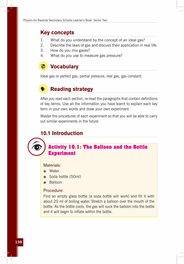
198
Physics for Rwanda Secondary Schools Learner’s Book Senior Two
Key concepts 1. What do you understand by the concept of an ideal gas?2. Describe the laws of gas and discuss their application in real life.3. How do you mix gases?4. What do you use to measure gas pressure?
Vocabulary
Ideal gas or perfect gas, partial pressure, real gas, gas constant.
y Reading strategy
After you read each section, re-read the paragraphs that contain definitions of key terms. Use all the information you have learnt to explain each key term in your own words and draw your own experiment.
Master the procedures of each experiment so that you will be able to carry out similar experiments in the future.
10.1 Introduction
Activity 10.1: The Balloon and the Bottle Experiment
Materials: Water Soda bottle (50ml) Balloon
Procedure: Find an empty glass bottle (a soda bottle will work) and fill it with about 20 ml of boiling water. Stretch a balloon over the mouth of the bottle. As the bottle cools, the gas will suck the balloon into the bottle and it will begin to inflate within the bottle.

199
Unit 10: Gas Laws’ Experiments
Questions:1. Why is the balloon being sucked into the bottle as the water
cools?2. What would happen if you heat the water again when the
balloon is still stretched over the bottle’s mouth?
The study of heat and its transformation to mechanical energy is called thermodynamics (which stems from Greek words meaning movement of heat). Thermodynamics is the dynamics of heat.
Statistical systems are systems with large numbers of particles (atoms and / or molecules). By large, we mean on the order of 6.022 x 10 23 (“Avogadro’s Number”, designated NA; one mol).
The measurable quantities are called “state variables”. As their name implies, their values depend only on the current state of the system, and not on the path taken to that state: they have no memory of their past values. Three of the most important state variables are temperature, pressure and volume. Temperature and pressure are “intrinsic” state variables, since their value does not depend on the “size” of the system. Volume is an “extrinsic” state variable, since its value does depend on the size of the system.
In thermodynamics, all temperatures are measured in “Kelvin” (K = Celsius + 273.15). Zero K is called “absolute zero”, since it is the lowest possible temperature. A temperature difference of 1K is equal to a temperature difference of 1C. We will not be concerned with pressure all that much, since most physiological functions assume a constant pressure equivalent to that of the atmosphere. We will typically measure volume in liters.
Let us find the volume of one mol of air using its density and gram molecular weight (the mass of one mol of a substance in grams is numerically equal to its molecular weight). If air is 78.08% N 2 (with molecular weight 28), 20.95% O 2 (32) and.93% Ar (40), the average molecular weight of air is 28.94g/mol. Since the density of air at standard temperature and pressure is 1.293kg/m 3, one mole of air then occupies 22.4l (0.224m 3).
A basic axiom for us will be the “Equipartition Theorem”.
It relates the energy of the particles in the system to the macroscopic temperature by stating that the average energy is 1
2 kT per degree of
freedom. (k is Boltzmann’s constant)

200
Physics for Rwanda Secondary Schools Learner’s Book Senior Two
10.2 Three gas lawsThe early gas laws were developed at the end of the eighteenth century, when scientists began to realise that relationships between the pressure, volume and temperature of a sample of gas could be obtained which would hold for all gases. Gases behave in a similar way over a wide variety of conditions because to a good approximation they all have molecules which are widely spaced, and nowadays the equation of state for an ideal gas is derived from kinetic theory. The earlier gas laws are now considered as special cases of the ideal gas equation, with one or more of the variables held constant.
Temperature in kelvins
¼0
½
¾1
¼
0
½¾1
0 100 200 300 400
0 10 20 30 40
Charles' LawIf a gas is held at a constant pressure, the volume is directly proportional to the absolute temperature. Heating a gas to double its original temperature doubles its volume.
Boyle's LawIf a gas is held at a constant temperature, the volume is inversely proportional to the pressure. Compressing a gas to half of its original volume doubles its pressure.
Increasing the temperature
Compressing the gas
Pressure in kilograms per square centimeter
Volu
me
in li
ters
Volu
me
in li
ters
Fig. 10.1: Boyle’s law and Charles’ law
10.2.1 Boyle’s law
Activity 10.2: Investigating Boyle’s law
Materials: A 50 ml syringe A small sized balloon
Fig. 10.2: A Syringe

201
Unit 10: Gas Laws’ Experiments
Procedure: First, trap a small amount of air in the balloon and tie a knot. Place the balloon in the syringe. With your finger, close the syringes' nose and press the piston
as in Fig. 10.2.
Questions:1. Why is the balloon decreasing the size as the pressure
increases?2. Why is its volume increasing as the pressure decreases?3. Discuss and explain where this can be observed in real life.
Robert Boyle (1627-1691), the English natural philosopher and one of the founders of modern chemistry; is best remembered for Boyle’s law (1662), a physical law that explains how the pressure and volume of a gas are related. It states that;
“The volume of a fixed mass of gas is inversely proportional to the pressure, provided the temperature remains constant”:
V ∝ 1 p or P∝ 1
v
PV = Ct where Ct is a constant.
We can re-write this equation as: P1V1 = P2 V2
This relationship means that pressure increases as volume decreases, and vice versa.
The cubic expansivity is always calculated in terms of an original volume at 00C. The cubic expansivity of a gas at constant pressure is thus defined as the fraction of its volume at 00C by which the volume of a fixed mass
of gas expands per Kelvin rise in temperature: γ = ∆V
V0 × ∆T where ∆V the
change in volume; V0 volume at 00C and ∆T change in temperature.
The value obtained is approximately γ= 1273 K
Notice:
W = PV = 1l × 1atm = 0.001m3 × 101325Pa = 101.325J

202
Physics for Rwanda Secondary Schools Learner’s Book Senior Two
Activity 10.3: Experiment to verify Boyle’s law
Visit this link to play the experiment game: http://www.uccs.edu/vgcl/gas-laws/experiment-1-boyles-law.html
In this experiment you will examine the effect of pressure on the volume of a gas at constant temperature and formulate the relationship between the two.
Fig. 10.3: Boyle’s law
Procedure:1. The experimental setup includes a closed cylinder with a
moveable piston containing a sample of gas (air), some 1 kg weights to place on the piston, and a pressure gauge and ruler to measure the pressure (in torr) and height of the piston (in cm) in the cylinder. (We will assume that the gas in the cylinder is at room temperature).

203
Unit 10: Gas Laws’ Experiments
2. Open the worksheet for Experiment 1. (You may want to enter the data within Excel, so that the graph can be created, then print out the results afterwards).
3. Click anywhere on the apparatus to start the lab. (If you are using Internet Explorer, you will have to click once to activate the control, then click again to start the lab).
4. The piston itself has a mass of 1kg. Click on the pressure gauge to see a close-up of the measuring devices. Record the pressure and height of the piston in the appropriate cells in the worksheet.
5. Click on the stack of weights to move one onto the piston. 6. Record the values in the next row of the worksheet. 7. Repeat steps 5 and 6 to record the pressure and height of
the piston with increasing numbers of weights. You may click on either the stack of weights on the bench to move one up to the piston, or the stack on the piston to return one to the bench.
10.2.2 Charles’ law
Activity 10.4: Demonstrating Charles’s Law by Expanding and Contracting a Balloon
Materials: Erlenmeyer flask or retort flask Water Electric heater ( Hot plate) Balloon
Procedure: Carry out the steps from A to F shown below and answer the questions:
a) Add a small amount of water to an Erlenmeyer flask as shown in Fig.10.4.

204
Physics for Rwanda Secondary Schools Learner’s Book Senior Two
Fig. 10.4: Erlenmeyer(retortflask)
b) Place the flask on a hot plate or burner as shown in Fig 10.5.
Fig. 10.5: Flask on a hot plate
c) Put the open end of a balloon over the opening of the flask as shown in Fig. 10.6.
Fig. 10.6: Theballoonknottedontheflask’sopening

205
Unit 10: Gas Laws’ Experiments
d) Observe the expansion of the balloon and record your observations.
e) Move the flask to an ice bath as in Fig 10.7.
Fig. 10.7: Theflaskintheicebath
f) What happens to the balloon?
Questions:1. What is causing the balloon to expand in step c?2. What is causing the balloon to contract in step e?3. Discuss and explain this effect in your own words?
Charles’ law or law of volumes (French chemist Jacques Charles 1787, relating volume and temperature at pressure constant):
The volume of a given amount of gas is directly proportional to absolute temperature when pressure is kept constant.
V ∝ TV = TC
p where C
p is a constant or V1
T1
= V2
T2
The process where the temperature and volume change at constant pressure is called Isobaric process.
10.2.3 Gay-Lussac’s law
Activity 10.5: How to Crush a Can with Air Pressure
You can crush a soda can using nothing more than a heat source and a bowl of water. This is a great visual demonstration of some simple scientific principles, including air pressure (Pressure law) and the concept of a vacuum. The experiment can be performed by teachers as a demonstration, or by mature learners under supervision.

206
Physics for Rwanda Secondary Schools Learner’s Book Senior Two
Using the following steps a) to e), do the experiment and notice the changes and observations.
a) Pour a little water into an empty soda can as in Fig. 10.8.
Fig. 10.8: Soda can
b) Prepare a bowl of ice water as in Fig.10.9.
Fig. 10.9: Bowl of ice water
c) Heat the can on the stove as in Fig.10.10.
Fig. 10.10: Heating the soda can

207
Unit 10: Gas Laws’ Experiments
d) Use the tongs to turn the hot can upside down into the cold water.
Fig. 10.11: The hot can in the cold water
e) What happens when you heat the can of water?
Questions:1. What happens inside the can when being heated?2. Why when inverted in cold water does the can collapse?3. Discuss and explain the phenomena of crushing can.
Pressure law or Third gas law (French chemist Joseph Guy-Lussac in 1809, relating temperature and pressure at constant volume):
“At constant volume, the pressure of a gas is directly proportional to the
absolute temperature” P∝ T
P=TCv where Cv is a constant or P1
T1 =
P2
T2
The process where the pressure and temperature change at constant volume is called Isochoric process.The pressure expansively of a gas at constant volume is defined as the fraction of its pressure at 00C by which the pressure of a fixed mass of gas increases per Kelvin rise in temperature.
β = ∆PP0 T
Where ∆P change in pressure and P0 pressure at 00CThe result is found to approximate very closely to β = 1
273 K.
We therefore arrive at the important conclusion that the pressure expansivity is equal to the volume expansivity. γ = β“The pressure of a fixed mass of gas at constant volume expands by
1273
of its pressure at 00C per kelvin rise in temperature”.

208
Physics for Rwanda Secondary Schools Learner’s Book Senior Two
10.3 Ideal gas
10.3.1 DefinitionWe can define an ideal gas as one which obeys Boyle’s law exactly and whose internal energy is independent of its volume.
At normal ambient conditions such as standard temperature and pressure, most real gases behave qualitatively like an ideal gas. Generally, deviation from an ideal gas tends to decrease with higher temperature and lower density, as the work performed by intermolecular forces becomes less significant compared to the particles’ kinetic energy, and the size of the molecules becomes less significant compared to the empty space between them.
The ideal gas model tends to fail at lower temperatures or higher pressures, when intermolecular forces and molecular size become important. At some point of low temperature and high pressure, real gases undergo a phase transition, such as to a liquid or a solid.
10.3.2 Ideal gas law
Activity 10.6: Investigating ideal gas
Study carefully the Fig. 10.12 and answer to the following questions:
volume 1 volume 2
gasmolecules
gaspressure
Fig. 10.12: Ideal gas containers

209
Unit 10: Gas Laws’ Experiments
Questions:1. What is the difference between molecules of gas contained in
the volume 1 and volume 2?2. Where is gas pressure greater between the two containers?3. Comment on the relationship between the volume change
and pressure change in each case.
The combined gas law or general gas equation is formed by the combination of the three laws, and shows the relationship between the pressure, volume and temperature for a fixed mass of gas:
1 1 2 2
1 2
p V p VT T
=
We can write this as an equation: PV = nRT; where;
P is the absolute pressure (Unit used: atmospheres, atm or Pascal). V is the volume (Unit used: litre, l or m3). n is the amount of substance (loosely number of moles of gas). R is the gas constant of proportionality, it is called the Universal
gas constant because its value is found experimentally to be the same for all gasses. Its value is R = 8.31447J/(mol.K) or R = 0.0821L • atm • mol–1 K–1
T is the temperature on the absolute temperature scale (Unit used: Kelvin).
These equations are exact only for an ideal gas, which neglects various intermolecular effects. However, the ideal gas law is a good approximation for most gases under moderate pressure and temperature.
This law has the following important consequences:
1. If temperature and pressure are kept constant, then the volume of the gas is directly proportional to the number of molecules of gas.
2. If the temperature and volume remain constant, then the pressure of the gas changes is directly proportional to the number of molecules of gas present.
3. If the number of gas molecules and the temperature remain constant, then the pressure is inversely proportional to the volume.

210
Physics for Rwanda Secondary Schools Learner’s Book Senior Two
4. If the temperature changes and the number of gas molecules are kept constant, then either pressure or volume (or both) will change in direct proportion to the temperature.
10.3.3 Dalton’s law of partial pressure
Activity 10.7: Partial pressure experiment
Use the information in table 10.1, to discuss and explain the effect of partial pressure of two or more gases.
Partial PressureTable 10.1: Dalton’s Law of Partial Pressures
Description of partial pressureA container of fixed volume at constant temperature holds a mixture of gas a and gas b at a total pressure of 4atm.
The total pressure in the container is proportional to the number of gas particles.
More gas particles = greater pressure. Less gas particles = lower pressure.
If each dot represents 1 mole of gas particles, then there are 48 moles of gas particles in this container exerting a total pressure of 4atm.
Illustration4atm pressure
gas a
gas b+
Imagine the container with no particles of gas b.
Only particles of gas a are present in the same container at the same temperature.
Now the container holds only 12 moles of gas particles instead of the 48 moles of gas particles it originally contained.
Since pressure is proportional to the number of gas particles, the pressure exerted by gas a = 12mol ÷ 48mol x 4atm = 1atm
1atm pressure
gas a

211
Unit 10: Gas Laws’ Experiments
Imagine the container with no particles of gas a.
Only particles of gas b are present in the same container at the same temperature.
Now the container holds only 36 moles of gas particles instead of the 48 moles of gas particles it originally contained.
Since pressure is proportional to the number of gas particles, the pressure exerted by gas b = 36mol ÷ 48mol x 4atm = 3atm
The total pressure in a gas mixture is the sum of the partial pressures of each individual gas.
Table 10.2: Dalton’s law of partial pressure
Ptotal = Pgas a + Pgas b
4atm pressure
gas a
gas b+
=
1atm pressure
gas a
+
3atm pressure
gas b
Examples1. 10g of nitrogen gas and 10g of helium gas are placed together
in a 10l container at 25oC. Calculate the partial pressure of each gas and the total pressure of the gas mixture. Calculate the moles (n) of each gas present: n = mass ÷ molar mass
Table 10.3: Molar mass
nitrogen (N2(g)) helium (He(g))
mass (g) 10 g 10 g
molar mass (g mol-1) 2 x 14 = 28 4
n = mass ÷ molar mass 10 ÷ 28 = 0.4 mol 10 ÷ 4 = 2.5 mol
3atm pressure
gas b

212
Physics for Rwanda Secondary Schools Learner’s Book Senior Two
Calculate the total moles of gas present = 0.4 + 2.5 = 2.9 mol
Calculate the total gas pressure assuming ideal gas behaviour:
PV = nRT
P = n × R × T ÷ V
n = 2.9 mol
R = 8.314
T = 25oC = 25 + 273 = 298K
V = 10l
P = 2.9 × 8.314 × 298 ÷ 10 = 718kPa (7 atm)
Partial pressure of nitrogen = n(N2) ÷ n(total) x total pressure Partial pressure of nitrogen = 0.4 ÷ 2.9 x 718kpa = 99kPa (0.9 atm)
Partial pressure of helium = n(He) ÷ n(total) x total pressure Partial pressure of helium = 2.5 ÷ 2.9 x 718 = 619kPa (6.1atm)
2. At 15oC, 25mL of neon at 101.3 kPa (1 atm) pressure and 75 mL of helium at 70.9kPa (0.7 atm) pressure are both expanded into a 1l sealed flask. Calculate the partial pressure of each gas and the total pressure of the gas mixture. Since the temperature and moles of each gas is constant, the pressure exerted by each gas is inversely proportional to its volume (Boyle’s Law).
PiVi = PfVf
Pf = PiVi ÷ Vf
Partial pressure Neon = 101.3kPa x 25 x 10-3L ÷ 1l = 2.5 kPa
Partial pressure Helium = 70.9kPa x 75 x 10-3L ÷ 1l = 5.3 kPa
Total pressure = 2.5 + 5.3 = 7.8kPa
Dalton’s law of Partial Pressures states that the pressure of a mixture of gases simply is the sum of the partial pressures of the individual components. Dalton’s Law is as follows:
1 1 2 2 ... n nPV PV PV PV= + + + where 1 2 ... nV V V V= + + +
The partial pressures of the individual components:
ii
VP PV
= at the same temperature

213
Unit 10: Gas Laws’ Experiments
10.3.4 Density of gasesDensity has the units of mass per unit volume
From ideal gas equation we have: PV = nRT ⇔ nV
= PRT
(n/V) has the units of moles/litre.
If we know the molecular mass of the gas, we can convert this into grams/litre (mass/volume).
The molar mass (M) is the number of grams in one mole of a substance. If we multiply both sides of the above equation by the molar mass:
nMV
= PMRT
The left hand side is now the number of grams per unit volume, or the mass per unit volume (which is the density)
Thus, the density (d) of a gas can be determined according to the following:
d = PMRT
Alternatively, if the density of the gas is known, the molar mass of a gas can be determined:
M = dRTP
Example: What is the density of carbon tetrachloride vapour at 714 torr and 125°C?
Answer: The molar mass of CCl4 is 12.0 + (4 × 35.5) = 154g/mol.
125°C in degrees Kelvin would be (273+125) = 398K.
Since we are dealing with torr, the value of the gas constant, R, would be 62.36l torr/mol K.
d = PMRT
= (714 torr)(154 g/mol)(6236 Ltorr/molK)(298K)
= 4.43g/L
Note: The standard atmosphere (atm) of pressure is approximately equal to air pressure at earth mean sea level and is defined as: 1 atm = 101325 Pa = 1013.25 mbar = 760 Torr

214
Physics for Rwanda Secondary Schools Learner’s Book Senior Two
10.3.4 Avogadro’s LawAvogadro’s Law (Italian scientist Amedeo Avogadro; 1776-1856), which is particularly useful in chemistry: For any gas, the ratio of volume of the gas to moles of the gas is constant: V
n = K and uses the molar
volume of a gas: 22.4l i.e. equal volumes of a gas at the same pressure
and temperature contain equal numbers of molecules. The number of molecules in a mole is known as Avogadro number:
NA = 6.02 × 10²³
Since the total number of molecules N in a gas is equal to the number the mole times the number of moles (N = nNA), then the ideal gas law can be written in terms of the number of molecules present:
pV = nRT = NNA
RT = NKT
Where K = 8.3156.023 ×1023
= 1.38 × 10⁻²³ J/K is the Boltzmann constant
and N is the number of molecules.
10.4 Unit 10 assessment
1. One atmosphere is equal to (Choose the correct answer):a) 760 cm Hgb) 760 mm Hgc) 101325 mm Hgd) 8.314 mm Hg
2. Which of the following quantities is not necessary to describe a gas? (Choose the correct answer)a) Volumeb) Temperaturec) Amountd) Pressure density
3. Dalton’s Law of Partial Pressures states that (Choose the correct answer): a) The total pressure exerted by a mixture of gases can be
determined using the Ideal Gas Constant.
b) The pressure of a gas is inversely proportional to both the temperature and number of moles of the gas.
c) The total pressure exerted by a mixture of gases is equal to the sum of the pressures exerted by the individual components in the mixture.

215
Unit 10: Gas Laws’ Experiments
d) You must take into consideration the vapour pressure of the solvent that you are using.
4. Convert centigrade temperature to Kelvin (Choose the correct answer): a) oC - 273.15b) oC + 273.15c) oF - 273.15d) oF + 273.15
5. 125cm3 of gas are collected at 150C and 755 mm of mercury pressure. Calculate the volume of the gas at s.t.p ( T= 297 K, V= 22.4 l/mol, P= 1 atm).
6. When tested in a cool garage at 120C a motor tyre is found to have a pressure of 190kPa. Assuming the volume of the air inside remains constant, what would you expect the pressure to become after the tyre has been allowed to stand in the sun so that the temperature rises to 320C? Atmospheric pressure = 100kPa.
7. Pure helium gas is contained in a leakproof cylinder containing a movable piston. The initial volume, pressure, and temperature of the gas are 15l, 2.0 atm, and 310K, respectively. If the volume is decreased to 12l and the pressure is increased to 3.5atm, find the final temperature of the gas.
8. Determine the volume of 1 mol of any gas at STP, assuming it behaves like an ideal gas.
9. A gas occupies a volume of 25.8l at 170C and under 690mm Hg. What volume will it occupy at 345K and under 1.85atm?
10. Oxygen is collected in a bottle, turned upside down, containing water at 270C. The barometer pressure measured in the bottle is 757 torr. Calculate the partial pressure of O2 knowing that the vapour pressure of water is 19.8 mm Hg at 270C.
11. We mix 200ml of N2 at 250C and under 250 torr with 350 ml of 02 at 250C and under 300 torr, the final pressure is 300 torr and the final volume is 300ml. What will be the final pressure at 250C?

ElectricityMagnetism (II)

217
Unit11
Magnetisation and Demagnetisation
Key unit competenceThe learner should be able to describe methods of magnetization and demagnetization.
My goalsBy the end of this unit, I will be able to:
describe a magnet. describe the magnetic properties of iron and steel. describe the methods of magnetising and demagnetising of
materials. explain the use of keepers in storing magnets. explain magnetic shielding. explain magnetisation using the domain theory. make temporary and permanent magnets. describe methods demagnetising magnets. explain demagnetisation using the domain theory. discuss methods of storing magnets. list and explain the applications of magnets. understand the social, economic, and technological implications
of using magnets. recognise the role of electromagnets in making electrical devices.

218
Physics for Rwanda Secondary Schools Learner’s Book Senior Two
Key concepts 1. What is needed to describe magnetism of a body?2. How to magnetise or demagnetise a body?3. When is a body magnetised or demagnetised?
Vocabulary
Magnetisation, demagnetisation, hammering, stroking, heating.
y Reading strategy
As you read this unit, put emphasis on all the key terms, their meaning and their structures. Study the diagrams so that you master how things work. Do all the experiments in this book about magnetisation.
11.1 Structure of an atom
Matter is made of tiny particles called atoms. An atom is made of three particles; electron, proton and neutron. These particles are called fundamental particles of an atom or sub atomic particles.
6 protons+ 6 neutrons
electron
proton
neutron
Carbon atom
Fig. 11.1: Atomic structure of a Carbon atom

219
Unit 11: Magnetisation and Demagnetisation
Electron (e–) - Electron is denoted by ‘e’ and is a negatively charged particle. The charge of an electron is equal to -1.6x10⁻¹⁹ Coulomb which is negative charge.
The relative mass of electron is 1/1836 of the mass of a Proton. Electrons revolve round the nucleus of atoms.
Mass of an electron me = 9.1 × 10⁻³¹ kg
Proton (p+) - Proton is denoted by ‘p’ and is a positively charged particle. The charge of proton is 1.6x10 -19 coulomb of positive charge and it is considered as unit a positive charge. Thus absolute charge over a proton is equal to +1.
The mass of a proton is equal to 1.6x10 -27 kg and considered equal to 1 as it is equal to the mass of 1 hydrogen atom. Proton is present in the nucleus of an atom.
Mass of a proton mp = 1.67 × 10⁻²⁷ kg
Neutron (n) – Neutron is denoted by ‘n’ and is a neutral particle.
The mass of neutron is 1.6 x 10 -27 kg. The relative mass of neutron is equal to 1. Neutron is present in the nucleus of atom.
Mass of a proton mn = 1.67 × 10⁻²⁷ kg
Nucleus – The centre of an atom is called nucleus. Nucleus comprises of neutron and proton. The nucleus of an atom contains the whole mass of an atom.
11.2 Magnetism
Activity 11.1: Investigation of magnetism
Materials: Magnets ( Different types) Ferromagnetic materials (such as nails, blades, iron filings) A pointing compass
Procedure: Carefully note the position of the pointer in the pointing compass
when it is alone and far away from any metal. Then bring a nail, blade and magnet one by one close to the
pointing compass.

220
Physics for Rwanda Secondary Schools Learner’s Book Senior Two
Questions:1. Describe the observation found in each situation.2. Discuss and explain the phenomena observed above.
Magnetism is a class of physical phenomenon that includes forces exerted by magnets. It has its origin in electric currents and the fundamental magnetic moments of elementary particles. These give rise to a magnetic field that acts on other currents and moments. Magnetism, phenomenon associated with the motion of electric charges can take many forms. It can be an electric current in a conductor or charged particles moving through space, or it can be the motion of an electron in atomic orbit.
11.2.1 Fundamentals of magnetismA permanent magnet is a piece of steel or a similar metal having its own magnetic field. Under ideal conditions, it will retain its magnetic strength for many years. Frequent drops, impacts or high temperatures weaken the magnetism. A piece of iron, called a keeper, fits over the magnet’s poles, helping it retain its magnetism during long periods in storage.
11.2.2 Ferromagnetism
Activity 11.2: Distinguishing magnetic and non-magnetic materials
With reference to the activity 11.1, explain what would happen if the materials listed below were put close to a magnet
A Piece of wooden bar Pieces of copper, aluminium,
steel brass, iron
A pen A piece of paper
Questions:1. Does a magnet attract all metals? Why?2. Does a magnet attract papers? Why?3. Differentiate the materials used in the above activity.
All permanent magnets exhibit what scientists call ferromagnetism. Under the right conditions, a ferromagnetic metal piece acquires its own field, becoming magnetised. Other kinds of metals, such as copper

221
Unit 11: Magnetisation and Demagnetisation
and aluminum, are not ferromagnetic. A magnet keeper is a piece of ferromagnetic material, and is made up of soft iron.
11.2.3 Magnetic Domain
Activity 11.3: Investigating magnetic domain
Materials: A permanent bar magnet Iron filings A stiff plain piece of paper
Procedure: Place the magnet on a flat surface and put the stiff plain paper
on it. Sprinkle the iron fillings all over the stiff paper. Gently, move the magnet in various directions.
Question:Discuss and explain the changes you are observing.
magnetisedunmagnetised
Fig. 11.2: Magnetic domain
In all ferromagnetic materials, microscopic bits of metal, called domains; have tiny magnetic fields. If their magnetic north and south poles line up, they cooperate and form a large field around the whole object. Impacts and heat scramble the orientation of the domains, weakening the field. Long periods of time also weaken magnets. During storage, a keeper reinforces the magnetic field, maintaining its strength for longer periods of time.

222
Physics for Rwanda Secondary Schools Learner’s Book Senior Two
11.2.4 Magnet Shapes
U-shaped magnet
bar magnet
cylindrical magnet
horseshoe magnet
Fig. 11.3: Shapes of magnetsPermanent magnets come in a variety of shapes: bars, cylindrical, horseshoe, (See Fig 11.3). Regardless of shape, every magnet has exactly one North and one South Pole, located magnetically at opposite ends of the field. Lines of magnetic force exit the magnet at the North Pole, curve around and re-enter it at the South Pole, and pass through the magnet’s material to the North Pole, forming a continuous loop. A horseshoe magnet has its north and south poles near each other, one pole at each end of the “U” shape. It makes an ideal candidate for a keeper, as it lies across both poles, forming a magnetic bridge between them.
11.2.5 Magnetic Circuit
NS NS NNNSSS NNNSSSSSS
Soft iron keeper
Fig. 11.4: A Magnetic circuit

223
Unit 11: Magnetisation and Demagnetisation
A magnetic field holds its strength best when the entire magnetic loop, or circuit, passes through a ferromagnetic metal at all points. A horseshoe magnet has an air gap between its two poles; the soft iron keeper closes this gap (see Fig. 11.4). A bar magnet, left by itself, will lose its strength over several months. Though a bar magnet has no “keeper,” if you lay two bars side by side, with the north pole of one touching the south pole of the other, they form a magnetic loop in iron and preserve the strength of both magnets.
S N
N S
Plastic or wood separator
Soft iron keeper
Soft iron keeper
11.3 Magnetisation and demagnetisation
Activity 11.4: Magnetisation by induction
Bring each of the metallic materials (copper, zinc, steel, soft iron, alluminium, soft iron) you wish to magnetise in close proximity to a strong magnet.
Then use the magnetised item to pick up drawing pins, paper-clips or iron filings.
If, after removing the magnet for a few minutes, there is a little adhering to the items; it will not be useful as a permanent magnet.
Gentle tapping, for example with a pencil, should leave some magnetised items still in contact.
Re-magnetising a magnet is often necessary if the magnet has been mistreated. Occasionally magnets are required to be made from pins etc. in order to make compasses. Also there are often requests to make a tool (e.g. screwdriver) magnetic so that it complies with a desired function. Sometimes a tool may have inadvertently become magnetic with unwanted consequences.

224
Physics for Rwanda Secondary Schools Learner’s Book Senior Two
There are a few methods of effecting the magnetisation of an object. However, it is important to make sure that the object is of the “right stuff”. Trying to make a permanent magnet from a rod not capable of retaining the magnetism will just waste time. So, what materials hold magnetism? Obviously any “old magnets” will be useful, certain steels and some iron based rods such as nails and the steel shafts of screwdrivers can also hold magnetism. Magnetically “soft” iron will magnetise but will lose the magnetism very quickly. This makes it ideal for electromagnets. Some stainless steels have very poor retention of the field so should not be used.
11.3.1 Electromagnet and electric bell
Electromagnet
Activity 11.5: Making an electromagnet
Materials: Metal rod like a long nail A long conducting wire A 12V battery or power supply A Switch Bulb Paperclip
Procedure: Coil the wire on the metal rod. Connect one end to the positive pole and another to the negative
pole. Make sure that you have connected the bulb in series with the
coil. Switch on, approach the paperclip and observe.
Questions:1. What changes have you observed by approaching the rod to
the paperclip?2. Discuss and explain how you would use the same techniques
in real life.

225
Unit 11: Magnetisation and Demagnetisation
A simple electromagnet consists of a coil of insulated wire wrapped around an iron core. A core of ferromagnetic material like iron serves to increase the magnetic field created.
The strength of the magnetic field generated is proportional to the amount of current through the winding magnetic field produced by a solenoid (coil of wire). This drawing shows a cross section through the center of the coil. The crosses are wires in which current is moving into the page; the dots are wires in which current is moving up out of the page.
Fig. 11.5: The parts and formation of an electromagnet
An electromagnet is a type of magnet in which the magnetic field is produced by an electric current. The magnetic field disappears when the current is turned off. Electromagnets usually consist of a large number of closely spaced turns of wire that create the magnetic field. The wire turns are often wound around a magnetic core made from soft iron; the magnetic core concentrates the magnetic flux and makes a more powerful magnet.
The main advantage of an electromagnet over a permanent magnet is that the magnetic field can be quickly changed by controlling the amount of electric current in the winding. However, unlike a permanent magnet that needs no power, an electromagnet requires a continuous supply of current to maintain the magnetic field.
Electromagnets are widely used as components of other electrical devices, such as motors, generators, relays, loudspeakers, hard disks, MRI machines, scientific instruments, and magnetic separation equipment. Electromagnets are also employed in industries for picking up and moving heavy iron objects such as scrap iron and steel.
Electric bellMany objects around you contain electromagnets. They are found in electric motors and loudspeakers. Very large and powerful electromagnets are used as lifting magnets in scrap yards to pick up, and then drop, old cars and other scrap iron and steel.

226
Physics for Rwanda Secondary Schools Learner’s Book Senior Two
Electric bells like the ones used in most schools also contain an electromagnet.
1. When the current flows through the circuit, the electromagnet makes a magnetic field.
2. The electromagnet attracts the springy metal arm.
3. The arm hits the gong, which makes a sound.
4. The circuit is broken and now the arm is out of position.
5. The electromagnet is turned off and the springy metal arm moves back.
6. The circuit is complete again.
Fig. 11.6 The Electric bell
The cycle repeats as long as the switch is closed. When the switch is pushed close, the circuit is completed and current flows through the electromagnetic coil.
11.3.2 Project 13.10 Make your own electric bellDescription
When you build your own model for Science Activity Workshop¸ remember that the magnetic motor is the most important part of your door bell. The idea is to create a circuit which will cause the electromagnet to generate a magnetic field. As a result, when an iron object is placed close to this magnet it is attracted towards the magnetic field. On pressing the bell, we are actually completing this circuit and thus eventually generating the sound.Kit Contents:
Nut / Bolts Cardboard base Iron strip Thumb tack
Safety pin Copper wire 9-v battery with cap Sand paper
You may also need scissors, a screw driver and cello-tape and an adult to help you.

227
Unit 11: Magnetisation and Demagnetisation
11.3.3 Demagnetisation by hammering
Hammering a rod will either allow it to become slightly magnetic if laid along a magnetic field (i.e. North -South) or demagnetise it if laid across the field lines (East-West). Notice that: Do not try to improve an existing magnet by hammering, it could easily reduce the field strength below that already present.
Fig. 11.7: Hammering a magnet
11.3.4 Magnetisation by strokingThis is, historically, the oldest form of consistently creating magnet. This produces magnets that are not as strong as the electrical methods. There are two methods which have traditionally been given the names “single stroke” and “double stroke".
S
S
S
S SN NSteel Bar Steel Bar
(a) Using one magnet
Magnet
Magnet Magnet
(b) Using two magnets
N
N
N
Fig. 11.8: Single stroke and double stroke North will be at the LHS (left hand side) of the bar
In the “single stroke” method, a magnet is drawn over the rod so as to go completely over the length of the rod. The magnetic domains are then pulled into alignment as the magnet passes. A useful method of realising the polarity of the induced magnetism is to consider the bar as a compass and which way it would point to the magnet as it finally leaves the bar. Best results are obtained after about twenty passes when the magnet is taken in a big loop away from the bar in between passes.
In the “double stroke” method two magnets are used at the same time in what may be thought of as a mirroring action. This

228
Physics for Rwanda Secondary Schools Learner’s Book Senior Two
method produces a stronger magnet than the single stroke method. Beware of polarity: If this method was to be done using two similar poles facing the bar it is possible to create a bar magnet with two like poles at either end! These are termed “consequent poles”.
11.3.5 Demagnetisation by HeatingThis method can create a magnetised bar without any apparent magnet being present (i.e. just using the earth’s field). A stronger field may, of course, be used by placing the cooling bar between two magnets or in an electrically created field. Care should be taken that the heated bar is thermally isolated from the field magnets, so as not to destroy their properties.
S
N
S
N
S NSSSSSSSSSSSSSSSSSSSSSSSSSSSSSSSSSSSSSSSSSSSSSSSSSSSSSSSSSSSSSSSSSSSSSSSSSSSSSSSSSSSSSSSSSSSSSSS NNNNNNNNNNNNNNNNNNNNNNNNNNNNNNNNNNNNNNNNNNNNNNNNNNNNNNNNNNNNNNNNNNNNNNNNNNNNNNNNNNNNNNNNNNNNNNNNNNNNNNNNNNNNNNN
The bar is heated to above a temperature (technically called the “curie point”) which varies from metal to metal, however most steels will be hotter at “red hot”. At this point the bar is no longer ferromagnetic but paramagnetic. As the bar cools it becomes ferromagnetic again and the domains are aligned with the external field.
Fig. 11.9: Heating a magnet
It may be of interest to try heating an old, weak magnet (all the paint will be burned off!) to red hot using a pair of tongs in a Bunsen flame and then placing it on a piece of heat mat with a rare-earth magnet underneath. Demagnetisation can be achieved by allowing the bar to cool in an East-West orientation shielded from magnetic influences.
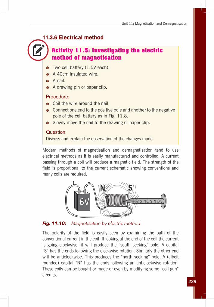
229
Unit 11: Magnetisation and Demagnetisation
11.3.6 Electrical method
Activity 11.5: Investigating the electric method of magnetisation
Two cell battery (1.5V each). A 40cm insulated wire. A nail. A drawing pin or paper clip.
Procedure: Coil the wire around the nail. Connect one end to the positive pole and another to the negative
pole of the cell battery as in Fig. 11.8. Slowly move the nail to the drawing or paper clip.
Question:Discuss and explain the observation of the changes made.
Modern methods of magnetisation and demagnetisation tend to use electrical methods as it is easily manufactured and controlled. A current passing through a coil will produce a magnetic field. The strength of the field is proportional to the current schematic showing conventions and many coils are required.
+ -
6V NNN SSS
N S
Fig. 11.10: Magnetisation by electric method
The polarity of the field is easily seen by examining the path of the conventional current in the coil. If looking at the end of the coil the current is going clockwise, it will produce the “south seeking” pole. A capital “S” has the ends following the clockwise rotation. Similarly the other end will be anticlockwise. This produces the “north seeking” pole. A (albeit rounded) capital “N” has the ends following an anticlockwise rotation. These coils can be bought or made or even by modifying some “coil gun” circuits.

230
Physics for Rwanda Secondary Schools Learner’s Book Senior Two
11.3.7 Demagnetising electricallyN
SN
a.c
Fig. 11.11: Demagnetisation by electric method
This involves taking the bar through the coil and an alternating current is used to create a field that swamps the existing field in a magnet. This is gradually reduced. This eventually becomes negligible. Alternatively the rod can be drawn out and away from a constant amplitude alternating the field.
The whole of the coil (240 turns), should be used. Nails placed in the coil will be felt to vibrate as the voltage is brought up to 6V. The nails can be moved so that all of their length passes through the centre of the coil at this voltage. The voltage is then slowly reduced to zero. The nails should now only have minimal magnetisation.
11.4 Magnetic keepers
If two magnets are placed side by side there will be mutual repulsion or attraction. This weakens the strength of the magnet. To prevent this, bar magnets are placed side by side with opposite poles near. A soft iron piece called a keeper is placed across the poles as shown in the figure. This soft iron piece provides a path for the magnetic field lines to form a continuous loop. Thus it helps in preserving the magnetic field.
Horse-shoeMagnet
Keeper
Keeper
(b)
(a)
S
S
S
N
N
N
N
N
N
S
S
S

231
Unit 11: Magnetisation and Demagnetisation
Horse-shoeMagnet
Keeper
Keeper
(b)
(a)
S
S
S
N
N
N
N
N
N
S
S
S
Fig. 11.12: Magnetic keepers
11.5 Magnetic shielding
Equipment sometimes requires isolation from external magnetic fields. In these cases shields made of high magnetic permeability metal alloys can be used, such as sheets of Permalloy and Mu-Metal, or with nanocrystalline grain structure ferromagnetic metal coatings. These materials don’t block the magnetic field, as with electric shielding, but rather draw the field into themselves, providing a path for the magnetic field lines around the shielded volume. The best shape for magnetic shields is thus a closed container surrounding the shielded volume. The effectiveness of this type of shielding depends on the material’s permeability, which generally drops off at both very low magnetic field strengths and at high field strengths where the material becomes saturated. So to achieve low residual fields, magnetic shields often consist of several enclosures one inside the other, each of which successively reduces the field inside it.
B = 0 Outside
B = 0 Inside Crew Compartment
Fig. 11.13: Magnetic shieldingBecause of the above limitations of passive shielding, an alternative used with static or low-frequency fields is active shielding; using a field created by electromagnets to cancel the ambient field within a volume. Solenoids and Helmholtz coils are types of coils that can be used for this purpose.

232
Physics for Rwanda Secondary Schools Learner’s Book Senior Two
11.6 Unit 11 assessment
1. Complete the following statement: ____are the charged parts of an atom.a) Only electrons
b) Only protons
c) Neutrons only
d) Electrons and neutrons
e) Electrons and protons
f) Protons and neutrons
2. TRUE or FALSE a) An object which is positively charged contains all protons and
no electrons.
b) An object which is negatively charged could contain only electrons with no accompanying protons.
c) An object which is electrically neutral contains only neutrons.
3. Identify the following particles as being charged or uncharged. If charged, indicate whether they are charged positively or negatively. (n = neutron, p = proton, e = electron)
Particle A Particle B Particle C
2e
8e
20n20p
8e2e
1e
12n11p
8e2e
8e
10n9p
4. The amount of charge carried by a lightening bolt is estimated at 10 Coulombs. What quantity of excess electrons is carried by the lightening bolt?
5. Respond to the following learner statement: “A positively charged object is an object which has an excess of positive electrons”.
6. A magnet attracts a piece of iron. The iron can then attract another piece of iron. On the basis of domain alignment, explain what happens in each piece of iron.
7. Why does hitting a magnet with a hammer cause the magnetism to be reduced?

233
Unit 11: Magnetisation and Demagnetisation
8. Examine the parts of an electric bell shown in the figure below. Discuss how it works when it is switched on. Make an electric bell and exhibit it.
F E
C
B
A
D
G
9. What causes the magnetism in a magnet? A bar magnet is heated. State the effect on magnetic properties.
10. What is the difference between temporary magnets and permanent magnets?

ElectricityStatic Electricity

235
Unit12
Applications of Electrostatic
Key unit competenceThe learner should be able to explain applications static charges.
My goalsBy the end of this unit, I will be able to:
explain and describe distribution of electric charges and metallic conductors.
explain electric force, electric field and electric potentials. discuss applications of electrostatic. define electric field strength. relate electric field patterns and charge distribution on
conductors of different shapes. evaluate applications of electrostatics in other fields (agriculture,
environment, industry). list the applications of electrostatics. identify possible hazards related to electrostatic and how to
avoid them.
Key concepts 1. What is needed to describe electrostatics?2. When and where can you observe the effects of electrostatics?3. How can you avoid an electric circuit from your house?4. How do you know the amount of electric potential from a charged
body?5. How do you calculate/tell/gauge the potential difference?6. What do charge distributions refer to?7. Describe different applications of electrostatics.

236
Physics for Rwanda Secondary Schools Learner’s Book Senior Two
Vocabulary
Electric field, electric potential, lightening arrestors, paint spray, laser printer, electrostatic precipitator, photocopy machine.
y Reading strategy
Read all the details of this unit. Perform calculations and do experimental work about an electric field. Hence, describe different application of electrostatics. Participate in all activities, be keen on procedures and observations.
12.1 Introduction
Activity 12.1: Investigating the electric charges on a rubbed balloon
Materials: 2 inflated balloons with string attached Your hair Aluminium can Woolen fabric
Procedure: Rub the 2 balloons one by one against the woolen fabric, and
then try moving the balloons together.
Questions:1. Do the balloons want to or are they unattracted to each other?
Rub 1 of the balloons back and forth on your hair then slowly pull it away.
2. Ask someone nearby what they can see or if there's nobody else around try looking in a mirror and discuss your observations. Put the aluminium can on its side on a table, after rubbing
the balloon on your hair again hold the balloon close to the can and watch as it rolls towards it, slowly move the balloon away from the can and it will follow.
3. Discuss and explain the observations made.

237
Unit 12: Applications of Electrostatic
Electrostatics is a branch of physics that deals with the phenomena and properties of stationary electric charges.
12.2 Static ElectricityA nylon garment often crackles when it is taken off. We say it has become charged with static electricity. The crackles are caused by tiny electric sparks which can be seen in the dark. Pens and combs made of certain plastics become charged when rubbed on the sleeve and can attract scraps of paper. Those materials are electrified, possess an electric charge or are electrically charged.
There are two kinds of charges in nature; negative and positive charges.
Like charges (+ and + or – and -) repel while unlike charges (+ and -) attract
The net amount of electric charge produced in any process is zero. This is known as the Law of Conservation of Electric Charge.
If one object or one region of space acquires a positive charge then an equal amount of negative charge will be found in neighbouring areas or objects.
12.3 Electric field
The Concept of Electric Field
Activity 12.2: Investigation of electric field
Materials: One battery cell (1.5V) A conducting wire 5 magnetic needles A slotted cardboard
Procedure: Arrange the materials as shown in Fig. 12.1. Remove the battery and note the changes on needles. Reconnect the battery and note the changes on needles.
Question:What is the main cause of the directions change when the battery is connected?

238
Physics for Rwanda Secondary Schools Learner’s Book Senior Two
Fig. 12.1: Electricfieldeffectonthemagneticneedles
When a small charged particle is located in the area surrounding a charged object, the charged particle experiences a force in accordance with Coulomb’s Law. The space around the charged object where force is exerted on the charged particle is called an electric field or electrostatic field.
Theoretically, an electric field due to charge extends to infinity but its effect practically dies away very quickly as the distance from the charge increases.
12.3.1 Electric Intensity or Field StrengthThe intensity of an electric field at any point is determined by the force acting on a unit positive charge (+1C) placed at that point.
If a positive point charge Q0 (also called test charge) is placed at any point in an electric field and it experiences an electric force F', the electric field vector E' at the point is the electric force divided by the magnitude of the test charge Q0
E ' = F'Q0
Electric field is an electric force per unit charge. The following points should note:
a) The electric field is a force per unit charge, it is therefore a vector, it has both magnitude and direction.
b) The electric field can be described (drawn) in terms of lines of force. Where the lines of force are close together, the intensity (strength) is high and where the lines are widely separated the intensity (strength) will below.

239
Unit 12: Applications of Electrostatic
12.2.2 Electric Intensity at a point in Electric FieldThe magnitude of the electric field at any point due to a point charge can be calculated using Coulomb’s Law.
a) Lets consider point charge Q, where Q is positive.
d P
+Q +Q0 FE
The electric field E' at point P (distance d away) due to an isolated +Q in a medium of permittivity can be calculated by imaging a very small charge +Q0 to be placed at P. By Coulomb’s Law.
F = 14πe
. –QQ0
d 2 (Q < 0)
where e is the permitivity of the medium between the changes. But E is the force per unit charge: E = F
Q0Therefore E = 14πe
. Q1
d2
b) Now consider point charge Q where Q is negative (-Q)
d P
– Q +Q0F E
The electric field E' at point P (distance d) due to an isolated –Q in a medium of permittivity can be calculated by imaging a very small charge +Q0 at P.
F = 14πe
. –QQ0
d2
E = FQo
∴ E = – Q4πed 2
Conclusion: The electric field due to a point charge always points away from the positive charge but towards the negative charge.
12.4 Electric field lines
Electric field lines (or line of force in an electric field) are an imaginary line drawn through an area or place. The line is drawn in such a way that the direction of its tangent is the same as the direction of the electric field at that point.

240
Physics for Rwanda Secondary Schools Learner’s Book Senior Two
AE
E
BA
B
The spacing of field lines gives a general idea of the magnitude of E at each point. Where E is strong the electric field lines are drawn closely together. Where E is weaker; the electric field lines are further apart.
EE
weakE weakstrong
a) Electric field lines produced by a single positive point charge.
+
The electric field lines always point away from positive charge
b) Electric field lines produced by a single negative point charge.
-
The electric field lines always point towards a negative charge.
c) Electric field lines produced by two equal and opposite point charges.
+
Note: The number of lines leaving the positive charge equals the number entering the negative charge.

241
Unit 12: Applications of Electrostatic
d) Electric field lines for two equal and positive charges.
++
e) Electric field lines for two equal and negative charges.
12.5 Electric field strength due to the distribution (superposition) of electric field
Consider many point charges, Q1, Q2, Q3, …Qn and the electric field caused by the individual point charges E1, E2, E3, ... En respectively.
The resultant electric field at a point P is the vector sum of the field at P due to each point charge distribution.
+
+
-
-Q
Q
Q
E
E E
EP
Q
2
23
3
n
n
1
1
E = E1 + E2 + E3 + ... + En
If r is the radius of a sphere the field strength E at its surface is given by
E = 14πe
. Qr 2

242
Physics for Rwanda Secondary Schools Learner’s Book Senior Two
12.6 Electric potential
Every charge has an electric force which extends theoretically up to infinity. Let us consider an isolated charge +Q fixed in space:
+QA Q0 (at ∞ moving towards A)
If a test charge Qo is placed at infinity, the force on it due to charge +Q is zero.
F = 9 × 10s QQo
d2 as d → ∞ F → 0
If the test charge Qo at infinity is moved towards +Q a force of repulsion acts on it and hence work is required to be done to bring it to a point like A. The work done by the electric force does not depend on the path taken by charge Qo, it is only dependent on the initial and final position, i.e. the electric force is conserved and the work done can be expressed in terms of potential energy, U.
The work done in bringing Qo from infinity to A is given by:
W = F . d = QQ o
4πed 2 . d
W = QQ o
4πed Then:
W ∞ – A = UB – UB = – (UA – U
∞)
= – ∆u (∆u = change in energy)
Where:
U∞ = QQ o
4πed ∞
Is the potential energy of the test charge Qo at d = ∞
UA = QQ o
4πed A
Is the potential energy of the test charge Qo at d = A
Hence, the electric potential energy U of a test charge Qo placed at distance d from the charge +Q is given by
U = QQ o
4πed

243
Unit 12: Applications of Electrostatic
The electric potential V at a point distance d from the charge Q is the electric potential energy U per unit charge associated with a test charge Qo placed at that point:
V = U Q oSince
U = QQ o
4πed
Then
V = QQ o
4πeQ od
V = Q4πed
Hence, electric potential at a point in an electric field is the amount of work done in bringing a unit of positive charge from infinity to that point, i.e.
V = WorkChange
= WQ
Where W is the work done to bring a charge of Coulomb from infinity to the point of consideration.
Unit: The SI unit of electric potential is volt (V) and may be defined as:
“The potential at a point in an electric field is 1 volt if 1 joule of work is done in bringing a unit of positive charge from infinity to that point against the electric field.”
12.6.1 Electric Potential DifferenceIn practice we are more concerned with potential difference (p.d.) between two points rather than their individual absolute potential.
The potential difference, p.d., between two points may be defined as:
“The potential difference between two points is the amount of work done in moving a unit of positive charge (+1C) from the point of lower potential to the point of higher potential.”
Consider two points A and B in the electric field of a charge +Q as shown here:
+Q A
V2 V1
B
The potential, V1, at B means that V1 joules of work have been done in bringing a unit of positive charge from infinity to B.
Let the extra work to bring the unit of positive charge (+1C) from B to A be in joules, therefore:
potential at A = V2 = V1 + W

244
Physics for Rwanda Secondary Schools Learner’s Book Senior Two
The p.d. between A and B is equal to V2 – V1 = V1 + W – V1 = W
The SI unit of p.d. is Volt and may be defined as:
“The p.d. between two points is 1V if 1 joule of work is done in bringing a unit of positive charge (+1C) from the point of lower potential to the point of higher potential.”
Let V be the potential difference between point A and B:
V = V2 – V1
By definition:
V = WQ
then V2 – V1 = WQ
So the work done is W = Q(V2 – V1)
Which is the work done for bringing a positive charge Q from B to A.
12.6.2 Potential of a Charged Sphere
Qr+
++ + +
++++
++
+++
++
Consider an isolated sphere of radius r metres placed in air and charged uniformly with Q Coulombs. The field has spherical symmetry i.e., lines of force spread out normally from the surface and meet at the centre of the sphere if projected backward. Outside the sphere, the field is exactly the same as though the charge Q on the sphere were concentrated at its centre.
Fig. 12.2: Field lines of a charged sphere
(i) Potential at the Sphere Surface
Due to the spherical symmetry of the field, we can imagine the charge Q on the sphere concentrated at its centre, O. The problem then reduces to finding the potential at a point r metres from a charge Q.
∴ Potential at the surface of sphere (Vs)
Vs = Q4πer
= 9 × 10⁹ Qr
Volts (in vacuum or air)
If the sphere is placed in medium (en) then;
V = Q 4πe
hr
= 9 × 10⁹ QE
hr
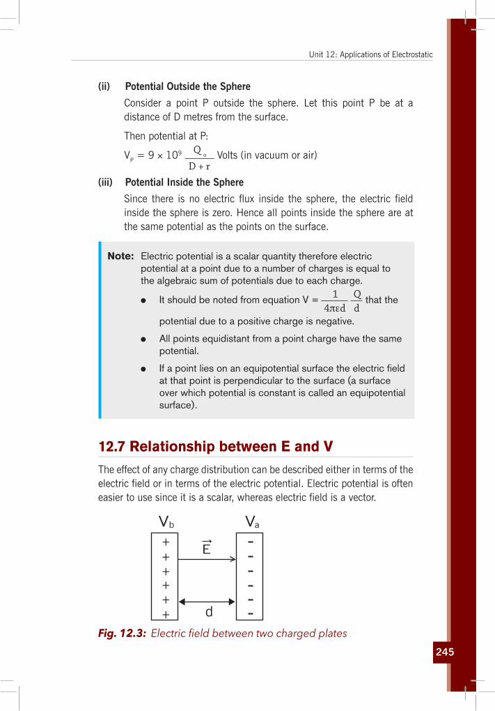
245
Unit 12: Applications of Electrostatic
(ii) Potential Outside the Sphere
Consider a point P outside the sphere. Let this point P be at a distance of D metres from the surface.
Then potential at P:
VP = 9 × 10⁹ Q o
D + r Volts (in vacuum or air)
(iii) Potential Inside the Sphere
Since there is no electric flux inside the sphere, the electric field inside the sphere is zero. Hence all points inside the sphere are at the same potential as the points on the surface.
Note: Electric potential is a scalar quantity therefore electric potential at a point due to a number of charges is equal to the algebraic sum of potentials due to each charge.
It should be noted from equation V = 14πed
Qd
that the
potential due to a positive charge is negative.
All points equidistant from a point charge have the same potential.
If a point lies on an equipotential surface the electric field at that point is perpendicular to the surface (a surface over which potential is constant is called an equipotential surface).
12.7 Relationship between E and V
The effect of any charge distribution can be described either in terms of the electric field or in terms of the electric potential. Electric potential is often easier to use since it is a scalar, whereas electric field is a vector.
+++
++
+
V
E
Vb
d
a
Fig. 12.3: Electricfieldbetweentwochargedplates

246
Physics for Rwanda Secondary Schools Learner’s Book Senior Two
The relationship between E and V for the case of a uniform electric field such as that between parallel plates whose p.d. is V where V = Vb – Va. The work done by the electric field to move a positive charge Q from a to b is W = Q(Vo – Vo)
We can also write the work done in terms of force, F, where F = QE. Thus W = F . d = Q . E . d
E is uniform electric field and d is the distance between parallel plates.
Thus Q(V0 – V0) = Q . E . d
Or V0 – V0 = Ed
Solving for E
E = V o – Vo
d or E = V
d Volt
metre
12.8 Charge distribution
12.8.1 The Electric Field due to Continuous Charge Distributions
q∆
E∆
P
r
r
Coulomb’s Law tells us the force between two point charges. Our variation tells us the Electric field due to a single point charge. What do we do if we have a continuous charge distribution?
We can sum up the electric field caused by each tiny, infinitesimal part of the charge distribution. This means an integral over the charge distribution:
For a single point charge Q, we had E = k Q
r2 where r is the distance from
the charge Q. Remember, E is only the
magnitude of the electric field.
Fig. 12.4: Partial charge distribution

247
Unit 12: Applications of Electrostatic
12.8.2 Electric flux
Area = A
EA
In electromagnetism, electric flux is the measure of flow of the electric field through a given area. Electric flux is proportional to the number of electric field lines going through a normally perpendicular surface. If the electric field is uniform, the electric flux passing through a surface of vector area S is:
φE = E . S
Fig. 12.5: Electricfluxthroughaflatarea
Where E is the electric field (having units of V/m), E is its magnitude, S is the area of the surface.
12.8.3 Gauss’s Law
The total of the electric flux out of a closed surface is equal to the charge enclosed divided by the permittivity ( ev).
(Where ev= 8.85 × 10⁻¹² P/m)
perpendicular
The sum ofthe flux isproportionalto the totalcharge enclosed.
E A∆Φ = ∆ E E
A∆ 0electric
Qε
Φ =
Fig. 12.6: Electricfluxthroughasphere(Gausslaw)
The electric flux through an area is defined as the electric field multiplied by the area of the surface projected in a plane perpendicular to the field.
Gauss’s Law is a general law applying to any closed surface. It is an important tool since it permits the assessment of the amount of enclosed charge by mapping the field on a surface outside the charge distribution. For geometries of sufficient symmetry, it simplifies the calculation of the electric field.

248
Physics for Rwanda Secondary Schools Learner’s Book Senior Two
12.8.4 Common Solid conductor shapes and charge distributiona) The Electric Field of a Conducting Sphere
QR
E
r
The electric field of a conducting sphere with charge Q can be obtained by a straightforward application of Gauss’ law. Considering a Gaussian surface in the form of a sphere at radius r > R , the electric field has the same magnitude at every point of the surface and is directed outward. The electric flux is then just the electric field times the area of the spherical surface.
Fig. 12.7: TheElectricfieldofaConductingSphere
2
0
4 QEA E rπε
Φ = = =
b) Distribution of Charge over the Surface of a Closed Conductor (Pear)
The charge around the conductor is measured using a proof plane. The proof plane is a small brass disc on an insulated handle.
Fig. 12.8: Distribution of charge on a pear-shaped closed conductor
It is first earthed to ensure there is no charge on the disc. The proof plane is then touched onto the surface of the conductor. The proportion of charge acquired by the disc when it is touched onto

249
Unit 12: Applications of Electrostatic
the surface of the conduction is proportional to the surface charge density of the conductor. The charge can be measured by touching the brass disc of the proof plane on the inside of a metal can standing on the top of the cap of a gold leaf electroscope. The deflection is an indication of the charge at the surface at that point.
Collect chargewith proof plane
Transfercharge
Testcharge
Electrons
Proof plane
Positively charged rod
charged rodPositively
A B
Fig. 12.9: Transfer of charges to a proof plane
If this process is repeated at various positions on the conductor, it is found that the least charge is found where the radius of the curvature of the conductor is greatest and that the charge is greatest where the surface of the conductor has the smallest radius of the curvature, i.e. where it is most pointed. If the radius of the curvature is very small, the density of charge can be large enough for charge leakage to occur creating a wind of ions.
c) Distribution of Charge over the Surface of a cylindrical Conductor
b
q
a
d A
d A
d A
E
c
E
E
0
900
0
900
A cylindrical Gaussian surface is used when finding the electric field or the flux produced by any of the following:
An infinitely long line of uniform charge An infinite plane of uniform charge An infinitely long cylinder of uniform
chargeAs example “field near infinite line charge” is given on the left;
Fig. 12.10: Cylindrical conductor

250
Physics for Rwanda Secondary Schools Learner’s Book Senior Two
d) Distribution of Charge over the Surface of a sharp point
Conductors are materials in which charges can move freely. If conductors are exposed to charge or an electric field, their internal charges will rearrange rapidly. For example, if a neutral conductor comes into contact with a rod containing a negative charge, some of that negative charge will transfer to the conductor at the point of contact. But the charge will not stay local to the contact point -- it will distribute itself evenly over the surface of the conductor. Once the charges are redistributed, the conductor is in a state of electrostatic equilibrium. It should be noted that the distribution of charges depends on the shape of the conductor and that static equilibrium may not necessarily involve an even distribution of charges, which tend to aggregate in higher concentrations around sharp points. This is explained in Fig. 12.11;
F
(a) (b) (c)
F
F
F FIIFII
FII
+
+ +
+ ++ ++ +++
++++++++
++
+
+
+
Fig. 12.11: Electrical Charge at a Sharp Point of a Conductor
Forces between like charges at either end of the conductor are identical, but the components of the forces parallel to the surfaces are different. The component parallel to the surface is greatest on the flattest surface and therefore moves charges away from one another more freely. This explains the difference in concentration of charge on flat vs. pointed areas of a conductor.
Similarly, if a conductor is placed in an electric field, the charges within the conductor will move until the field is perpendicular to the surface of the conductor. Negative charges in the conductor will align themselves towards the positive end of the electric field, leaving positive charges at the negative end of the field. The conductor thus becomes polarised, with the electric field becoming stronger near the conductor but disintegrating inside it. This occurrence is similar to that observed in a Faraday cage, which is an enclosure made of a conducting material that shields the inside from an external electric charge or field or shields the outside from an internal electric charge or field.

251
Unit 12: Applications of Electrostatic
12.9 Application of electrostatics
12.9.1 Point discharge (Lightening)
Activity 12.3: Lightening description
Take the case of the phenomena of lightening and thunderstorm, and then answer to the following questions.
Questions:1. What do you think are lightening and thunderstorm?2. Suggest the causes of thunderstorm and lighting.3. Discuss and explain how one can create a protection from
lightening and thunderstorm.
+ +
+++
+++
++
+ ++
+
+
++
+
Lightning can travel from cloud to ground
Lightning can travel from ground to cloud
Lightning can travel from cloud to cloud
Negatively charged cloud
Positively charged cloud
Fig. 12.12: Lightening
Lightening is a sudden electrostatic discharge during an electrical storm between electrically charged regions of a cloud (called intra-cloud lightening or IC), between that cloud and another cloud (CC lightening), or between a cloud and the ground (CG lightening).
The charged regions in the atmosphere temporarily equalise themselves through this discharge referred to as a strike if it hits an object on the ground, and a flash if it occurs within a cloud. Lightening causes light in the form of plasma, and sound in the form of thunder. Lightening may be seen and not heard when it occurs at a distance too great for the sound to carry as far as the light from the strike or flash. For the case of RWANDA, it is taken as the world’s place with high potential of lightening and thunderstorms.

252
Physics for Rwanda Secondary Schools Learner’s Book Senior Two
Activity 12.4: Lightening situation in the world
Read the article below (Fig. 12.13) and answer to the following questions.
Questions:1. Which part of Rwanda is mostly affected by lightening?2. Discuss the consequences of lightening in Rwanda.3. Discuss and comment on how scientists discovered that in
Rwanda there is more lightening than other places in the world.
4. How would Rwandans protect themselves from lightening.
Fig. 12.13: The comparison of lightening in Rwanda and other countries in the world

253
Unit 12: Applications of Electrostatic
12.8.2 Lightening Arrestors
Activity 12.5: Visiting lightening arrestors
Visit any building which has lightening arrestors and answer the following questions.
Questions:1. Why do people use lightening arrestors on their houses/
buildings?2. How and when do you think lightening arrestors work?
+ +
++
+
++
++
++
+ +
++
++
++
+
+
++++
++
++
+
Current conductedto ground
Lightening rod
Fig. 12.14: Lightening ArrestorsA lightening arrester is a device used on electrical power systems and telecommunication systems to protect the insulation and conductors of the system from the damaging effects of lightening. The typical lightening arrester has a high-voltage terminal and a ground terminal. When a lightening surge (or switching surge, which is very similar) travels along the power line to the arrester, the current from the surge is diverted through the arrestor, in most cases to earth.
In telegraphy and telephony, a lightening arrestor is placed where wires enter a structure, preventing damage to electronic instruments within and ensuring the safety of individuals near them. Smaller versions of lightening arresters, also called surge protectors, are devices that are connected between each electrical conductor in power and communication systems and the Earth. These prevent the flow of the normal power or signal currents to ground, but provide a path over which high-voltage lightening current flows, bypassing the connected equipment. Their purpose is to limit the rise in voltage when a communication or power line is struck by lightening or is near to a lightening strike.

254
Physics for Rwanda Secondary Schools Learner’s Book Senior Two
If protection fails or is absent, lightening that strikes the electrical system introduces thousands of kilovolts that may damage the transmission lines, and can also cause severe damage to transformers and other electrical or electronic devices. Lightening-produced extreme voltage spikes in incoming power lines can damage electrical home appliances or even cause death.
Components
Fig. 12.15: The Simple spark gap device diverts lightening strike to the ground (earth)A potential target for a lightening strike, such as a television antenna, is attached to the terminal labelled A in the photograph. Terminal E is attached to a long rod buried in the ground. Ordinarily no current will flow between the antenna and the ground because there is extremely high resistance between B and C, and also between C and D. The voltage of a lightening strike, however, is many times higher than that needed to move electrons through the two air gaps. The result is that the electrons go through the lightening arrester rather than travelling on to the television set and destroying it.
A lightening arrester may be a spark gap or may have a block of a semiconducting material such as silicon carbide or zinc oxide. “Thyrite” was once a trade name for the silicon carbide used in arresters. Some spark gaps are open to the air, but most modern varieties are filled with a precision gas mixture, and have a small amount of radioactive material to encourage the gas to ionize when the voltage across the gap reaches a specified level. Other designs of lightening arresters use a glow-discharge tube (essentially like a neon glow lamp) connected between the protected conductor and ground, or voltage-activated solid-state switches called varistors or MOVs.
Lightening arresters built for power substation use are immense devices, consisting of a porcelain tube several feet long and several inches in diameter, typically filled with discs of zinc oxide. A safety port on the side of the device vents the occasional internal explosion without shattering the porcelain cylinder.
Lightening arrestors are rated by the peak current they can withstand, the amount of energy they can absorb.

255
Unit 12: Applications of Electrostatic
12.9.3 Paint spraying, Photocopy Machines/Xerography and Laser Printers
12.8.3.1 Paint Spraying
Electrostatic spray painting can reduce the problems of uneven coverage and overspray that result from using a regular spray painter. The paint is electrostatically charged in a couple of different ways. One type of system applies a negative electric charge to the paint while it is in the reservoir. Other systems apply the charge in the barrel of the spray painter gun.
Fig. 12.16: A Paint sprayer
The paint is propelled through the gun, rubbing against the side, and gaining a static electric charge.
GROUNDEDOBJECT
CHARGED PAINT
GROUNDEDOBJECT
Fig. 12.17: The function paint spraying
Since the paint particles all have the same charge, they repel each other. This helps to distribute the paint particles evenly and get uniform coverage. Usually the object being painted is metal and grounded but almost any product can be finished electrostatically. A metal object may need to be placed behind the object to create a ground or it can be sprayed with a conductive primer. The paint particles have a charge so they are attracted to the opposite charge of the object being painted. This makes the particles less likely to stay in the air.
Electrostatic spray painting has distinct advantages. It creates a strong bond. It also covers a three dimensional object more evenly with a good edge and wrap around coverage. It saves paint by using the least amount of paint since it has a high transfer efficiency. Also the finish will look better because it has a uniform paint thickness.

256
Physics for Rwanda Secondary Schools Learner’s Book Senior Two
There are some disadvantages as well. Material to be sprayed must be conductive or made conductive for bonding. Care has to be taken with this equipment as guns can be delicate and bulky. It requires the use of grounding as improper usage can be a safety or fire hazard. Lastly it is more expensive to apply than regular spray painting.
12.8.3.2 Photocopy Machines /Xerography
Activity 12.6: Printers and photocopier
Visit a printing stationary shop, where they do printing and photocopy and then discuss about the following questions.
Tell the shop keeper to show you different parts of a printer and photocopier.
Questions:1. List and describe the different machines you have seen.2. Discuss and explain how a printer and photocopier function.3. Explain and discuss the functions of the following parts in
application of electrostatics:a) Scanner b) Cartridgec) Fuse d) Toner
4. Differentiate a printer from a photocopier.
A photocopier (also known as a copier or copy machine) is a machine that makes paper copies of documents and other visual images quickly and cheaply. Most current photocopiers use a technology called xerography, a dry process that uses electrostatic charges on a light sensitive photoreceptor to first attract and then transfer toner particles (a powder) onto paper in the form of an image. Heat, pressure or a combination of both is then used to fuse the toner onto the paper. (Copiers can also use other technologies such as ink jet, but xerography is standard for office copying.)Fig. 12.18: Photocopier

257
Unit 12: Applications of Electrostatic
Xerographic office photocopying was introduced by Xerox in 1959, and it gradually replaced copies made by Verifax, Photostat, carbon paper, mimeograph machines, and other duplicating machines.
15w
1
2
3
4
Cylindrical drumphotoconductor
Light
Toner
Paper
How it works (using xerography)
Photocopying is widely used in the business, education, and government sectors. While there have been predictions that photocopiers will eventually become obsolete as information workers increase their use of digital document creation, storage and distribution, and rely less on distributing actual pieces of paper, as of 2015, photocopiers continue to be widely used. In the 2010s, there is a convergence in some high-end machines between the roles of a photocopier, a fax machine, a scanner, and a computer network-connected printer. As of 2015, some high-end machines can copy and print in colour.
Fig. 12.19: The function of a Photocopier
Schematic overview of the xerographic photocopying process:
1. Charging: The cylindrical drum is electrostatically charged by a high voltage wire called a corona wire or a charge roller. The drum has a coating of a photoconductive material. A photoconductor is a semi-conductor that becomes conductive when exposed to light.
2. Exposure: A bright lamp illuminates the original document, and the white areas of the original document reflect the light onto the surface of the photoconductive drum. The areas of the drum that are exposed to light become conductive and therefore discharge to the ground. The area of the drum not exposed to light (those areas that correspond to black portions of the original document) remains negatively charged.
3. Developing: The toner is positively charged. When it is applied to the drum to develop the image, it is attracted and sticks to the areas that are negatively charged (black areas), just as paper sticks to a balloon with a static charge.

258
Physics for Rwanda Secondary Schools Learner’s Book Senior Two
4. Transfer: The resulting toner image on the surface of the drum is transferred from the drum onto a piece of paper with a higher negative charge than the drum.
5. Fusing: The toner is melted and bonded to the paper by heat and pressure rollers.A negative photocopy inverts the colours of the document when creating a photocopy, resulting in letters that appear white on a black background instead of black on a white background. Negative photocopies of old or faded documents sometimes produce documents which have better focus and are easier to read and study.
12.8.3.3 Application of Electrostatics in Laser Printer
Activity 12.7: The printing process with laser printer
Observe the process shown in Fig.12.20 and then try to interrupt the laser printer when it has started printing and ask someone to help in opening the printer and remove the cartridge; and check on the cylinder of the cartridge.
Questions:Comment and discuss your observations.
(d) Transfering the toner to the paper
(e) Laser printer drum
Laserbeam
Negativelycharged toner
Light causes some areasof drum to become eletricallyconducting, removing positivecharge
(c) Applying the toner(b) Imaging the document(a) Charging the drum
Selenium-coateddrum
Interlaced patternof laser lines
Lens

259
Unit 12: Applications of Electrostatic
(d) Transfering the toner to the paper
(e) Laser printer drum
Laserbeam
Negativelycharged toner
Light causes some areasof drum to become eletricallyconducting, removing positivecharge
(c) Applying the toner(b) Imaging the document(a) Charging the drum
Selenium-coateddrum
Interlaced patternof laser lines
Lens
Fig. 12.20: The xerography process
The xerography process:
a) The photoconductive surface of the drum is positively charged.
b) Through the use of light source and lenses, an image is formed on the surface in the form of positive charges.
c) The surface containing the image is covered with a negatively charged powder, which adheres only to the image area.
d) A piece of paper placed over the charged powder migrate to the paper. The paper is the heat-treated to fix the powder.
e) A laser printer operates similarly except that the image is produced by turning a laser beam on and off as it sweeps across the selenium-coated drum.
Laser printing is an electrostatic digital printing process. It produces high-quality texts and graphics (and moderate-quality photographs) by repeatedly passing a laser beam back and forth over a negatively charged cylinder called a “drum” to define a differentially-charged image. The drum then selectively collects electrically charged powdered ink (toner), and transfers the image to paper, which is then heated in order to permanently fuse the text and/or imagery. As with digital photocopiers and multifunction/all-in-one inkjet printers, laser printers employ a xerographic printing process. However, laser printing differs from analog photocopiers in that the image is produced by the direct scanning of the medium across the printer’s photoreceptor. This enables laser printing to copy images more quickly than most photocopiers.

260
Physics for Rwanda Secondary Schools Learner’s Book Senior Two
12.10 Van de Graff generator, electrostatic precipitator
12.10 The Van de Graff Generator When a charged conductor is placed in contact with the inside of a hollow conductor, all of the charge conductor is transferred to the hollow conductor. In principle, the charge on the hollow conductor and its electric potential can be increased without limit by repetition of the process.
This type of generator is used extensively in nuclear physics research. A schematic representation of the generator is given in Figure 12.21. Charge is delivered continuously to a high-potential electrode by means of a moving belt of insulating material. The high-voltage electrode is a hollow conductor mounted on an insulating column. The belt is charged at a point by means of a corona discharge between comb-like metallic needles and a grounded grid. The needles are maintained at a positive electric potential of typically 104 V. The positive charge on the moving belt is transferred to the hollow conductor by a second comb of needles at point B. Because the electric field inside the hollow conductor is negligible, the positive charge on the belt is easily transferred to the conductor regardless of its potential. In practice, it is possible to increase the electric potential of the hollow conductor until the electrical discharge occurs through the air. Because the “breakdown” electric field in air is about 3 x 10⁶ V/m, a sphere 1m in radius can be raised to a maximum potential of 3 x 10⁶ V. The potential can be increased further by increasing the radius of the hollow conductor and by placing the entire system in a container filled with high-pressure gas.

261
Unit 12: Applications of Electrostatic
Hollow conductor
Schematic diagram of aVan de Graff generator.A charge is transsferredto the hollow conductorat the top by means of amoving belt. The chargeis deposited on the beltat point A and transferredto the hallow conductor atpoint B.
Groundedgrid
A
Insulator
Belt
Ground
B
Fig. 12.21: The Van de Graff generator
Van de Graaff generators can produce potential differences as large as 20 million volts. Protons accelerated through such large potential differences receive enough energy to initiate nuclear reactions between themselves and various target nuclei. Smaller generators are often seen in science classrooms and museums. If a person insulated from the ground touches the sphere of a Van de Graaff generator, his or her body can be brought to a high electric potential. The hair acquires a net positive charge, and each strand is repelled by all the others. The result is a scene such as that depicted in the Fig. 12.22.
In addition to being insulated from the ground, the person holding the sphere is safe in this demonstration because the total charge on the sphere is very small (on the order of 1μC). If this amount of charge accidentally passed from the sphere through the person to the ground, the corresponding current would do no harm.

262
Physics for Rwanda Secondary Schools Learner’s Book Senior Two
Activity 12.8: Threadlike flows of electric wind
When placed in a strong e-field, human hair, eyelashes, and other sharp objects create tiny coronas which emit "electric wind". These invisible flows of air are extremely narrow and rapid, and their effects can be made visible by using dry-ice fog. (Fig. 12.22)
Materials: A VDG ( Van de Graaf ) machine Wire and tape (or clip-leads) Tray of warm water sitting on an insulator Chips of dry ice Dark paper (submerged in the water for contrast)
Procedure: Drop several CO2 chips in the water so that a thin layer of fog
forms. Use tape and a wire to connect the tray to the sphere of your
VDG. Charge the tray with respect to the ground. Move your hand slowly over the fog, keeping your hand a few
centimeters above it. You'll see small mysterious furrows being carved in the fog by the invisible, narrow threads of "electric wind."
If your hands are extremely clean (no sharp microscopic defects), try wetting your fingers and brush them across fuzzy clothing to pick up some microscopic lint. Or instead try waving a torn bit of paper over the mist. The sharp paper fibers seem to generate these "threads" of charged air fairly well. If humidity is very low, then perhaps the paper should be made moist.
Wave your hand fast, and the spots in the mist will follow your hand's motions. Pull your hand back, and the spots still appear.
Form a "thread", then wave a charged object near it. The spot in the mist moves, indicating that the "thread" is being deflected.
Use a soda straw to blow hard across a "thread". The corresponding spot in the mist will move only a small amount.
Drop some short (1cm) pieces of hair onto the charged water surface. They will stand on one end, emit "threads" upwards, and narrow flows of entrained mist will be seen to project upwards from the fog layer.

263
Unit 12: Applications of Electrostatic
Tiny fibersact as “emitters”
Air streams
Hi-volt supply(negion generator)
Dry-ice chip
Water-filledcookie sheet
Plasticcups
Fig.12.22: The Van de Graff Experiment
12.10.2 The Electrostatic Precipitator Insulator
WeightDirtyair in
Clean air out
Dirt out
Fig. 12.23: The Electrostatic precipitator
One important application of electrical discharge in gases is the electrostatic precipitator. This device removes particulate matter from combustion gases, thereby reducing air pollution. Precipitators are especially useful in coal-burning power plants and in industrial operations that generate large quantities of smoke. Current systems are able to eliminate more than 99% of the ash from smoke.

264
Physics for Rwanda Secondary Schools Learner’s Book Senior Two
Figure 12.23 shows a schematic diagram of an electrostatic precipitator. A high potential difference (typically 40 kV to 100 kV) is maintained between a wire running down the center of a duct and the walls of the duct, which are grounded. The wire is maintained at a negative electric potential with respect to the walls, so the electric field is directed toward the wire. The values of the field near the wire become high enough to cause a corona discharge around the wire; the discharge ionizes some air molecules to form positive ions, electrons, and such negative ions as O2. The air to be cleaned enters the duct and moves near the wire. As the electrons and negative ions created by the discharge are accelerated toward the outer wall by the electric field, the dirt particles in the air become charged by collisions and ion capture. Because most of the charged dirt particles are negative, they too are drawn to the duct walls by the electric field. When the duct is periodically shaken, the particles break loose and are collected at the bottom. In addition to reducing the level of particulate matter in the atmosphere (compare Figs. 12.23b and c), the electrostatic precipitator recovers valuable materials in the form of metal oxides.
Activity 12.9: Investigating electrostatic precipitator
Materials: ½ Teaspoon ground black pepper (or small bits of paper) 1 balloon 1 sheet of white paper
OR Ground black pepper 1 piece of plastic (PVC) tubing, 90-150cm long, 6.5cm in
diameter 1 plastic shopping bag. 1 sheet of white paper.
Procedure: 1. Give each learner a balloon and some black pepper on a
sheet of paper.2. Ask the students to blow up their balloons and rub them on
their hair or a piece of cloth.3. Hold the balloon over the pepper on the paper. What happens
to the pepper? See Fig. 12.24

265
Unit 12: Applications of Electrostatic
Fig.12. 24: Materials required for the balloon model electrostatic precipitator. Close-up of pepper grains on the balloon surface.
4. Record your observation.5. Pull the plastic grocery bag through the PVC tube so that the
inside edge of it becomes charged with static electricity. 6. Gently pour some pepper through the tube while holding it
over a piece of white paper. Some pepper should stick to the inside of the tube (in the same way that it was attracted to the balloon).
7. Note your observations.
Questions:1. Does the electrostatic precipitator remove all of the
particulates? 2. How does this compare to the efficiency of a wet scrubber?
Which one is better? 3. If the precipitators are more efficient, why would you ever
want to use a wet scrubber?
12.11 Unit 12 assessment
1. Two small spheres spaced 35.0cm apart have equal charge. How many excess electrons must be present on each sphere if the magnitude of the force of repulsion between them is 2.20 × 10⁻²¹N?

266
Physics for Rwanda Secondary Schools Learner’s Book Senior Two
2. A point charge q1 = –7 nC is at the point x1 = 0.6m, y1 = 0.8 m, and a second point charge q2 = 4 nC is at the point,. Find the magnitude and direction of the net electric field at the origin. x2 = 0.6 m and y2 = 0m
3. What must the charge (sign and magnitude) of a particle of mass 5g be for it to remain stationary when placed in a downward-directed electric field of magnitude 800nC?
4. What is the magnitude of an electric field in which the electric force on a proton is equal in magnitude to its weight?
5. A particle has a charge of –8.00nC. Find the magnitude and direction of the electric field due to this particle at a point 0.5m directly above it.
6. Two particles having charges of 0.70nC and 12nC are separated by a distance of 2m. At what point along the line connecting the two charges is the net electric field due to the two charges equal to zero?
7. Each square centimeter of the surface of an infinite plane sheet of paper has 4 × 10⁶ excess electrons. Find the magnitude and direction of the electric field at a point 6.00cm from the surface of the sheet, if the sheet is large enough to be treated as an infinite plane.
8. What is the strength and direction of the electric field 3.74cm on the left hand side of a 9.1 nC negative charge?
9. At what distance from a negative charge of 5.536nC would the electric field strength be 1.90 x 10⁵nC?
10. If it takes 88.3J of work to move 0.721C of charge from a positive plate to a negative plate, what is the potential difference (voltage) between the plates?
11. Two parallel oppositely charged plates are 5.1cm apart. The potential difference, in volts, between the plates is 44.6V. Find the electric field strength between them.
12. Explain Van De Graff generator?13. What do you mean by a lightening conductor?14. What is lightening and thunderstorms?15. What is Electrostatic Shielding?16. What are Conductors?17. What will be the electric field intensity due to a group of charges?18. What are Electric Lines of Force?

ElectricityDirect Current

268

269
Unit13
Arrangement of Resistors in an Electric Circuit
Key unit competenceThe learner should be able to describe arrangement of resistors in a simple electric circuit.
My goalsBy the end of this unit, I will be able to:
arrange resistors in a simple electric circuit. explain the magnetic effect of an electric current. explain how grounding, fuses, and circuit breakers protect
people against electrical shocks and short circuits. state and explain the effect of electric current. analyse arrangement of resistors in a simple electric circuit. construct a simple electric circuit with resistors in series and
parallel, ammeter and voltmeter. Illustrate the effect of electric current. apply knowledge of safety to prevent circuits from overheating
devices (fuses and circuit breakers). predict what would happen in a house without a fuse or circuit
breakers with overloaded electric circuit. measure electric current and potential difference using an
ammeter and voltammeter.

270
Physics for Rwanda Secondary Schools Learner’s Book Senior Two
Key concepts 1. What do you understand by an electric resistor?2. What is an electric circuit?3. How to make your own electric circuit.4. What are materials needed to form a complete simple circuit?5. Describe different arrangement of resistors in electric circuits.6. How do you recognise the domestic electric energy use?
Vocabulary
Simple electric circuit, electric potential, potential difference, electric bell, electromagnet, electrolysis, heat effect, chemical effect.
y Reading strategy
After you have read each section, pay attention to every detail especially the diagrams, illustrations and instructions for every practical work. Perform calculations on electricity and set up your own circuit diagrams.
13.1 Simple circuit elements
Activity 13.1: Making a simple electric circuit
Materials: 6-volt battery 6-volt incandescent lamp Jumper wires Breadboard Terminal strip
With the following given instructions, use provided materials and present your observations.

271
Unit 13: Arrangement of Resistors in an Electric Circuit
Schematic diagram and illustration:
Battery
Battery
Lamp
Lamp
+-
Fig. 13.1: Diagram and illustration of a simple electric circuit
Instructions:a) Connect the lamp to the battery as shown in the illustration
above (Fig. 13.1)
b) Connect the lamp as shown in Fig. 13.2 from step (A) to step (D)
Battery
BatteryBattery
Battery
No light
Lamp
Lamp
Lamp
Lamp
No light
No lightNo light
B
DC
A
break in circuit
break in circuit
break in circuit
break in circuit+
-
+-
+-
+-
Fig. 13.2: Illustration of break in electric circuit
c) Using your multimeter set to the appropriate “DC volt” range as shown in Fig.13.3 below, measure voltage across the battery, across the lamp, and across each jumper wire. Familiarise yourself with the normal voltages in a functioning circuit.
d) Now, “break” the circuit at one point and re-measure voltage between the same sets of points, additionally measuring voltage across the break like this:

272
Physics for Rwanda Secondary Schools Learner’s Book Senior Two
BatteryLamp
No light+-
COMA
VΩOFF
AV
V AΩ
V AV
V A
Fig. 13.3: Voltage drop display
Questions:1. Which voltages measure the same as before? 2. Which voltages are different since introducing the break? 3. How much voltage is manifest, or dropped across the break? 4. What is the polarity of the voltage drop across the break, as
indicated by the meter?
Re-connect the jumper wire to the lamp, and break the circuit in another place. Measure all voltage “drops” again, familiarising yourself with the voltages of an “open” circuit.
Activity 13.2: Using a breadboard in an
electric circuit
Materials: Use the same materials as in activity 13.1 Essential configuration needed to make a circuit. Normal voltage drops in an operating circuit. Importance of continuity to a circuit. Working definitions of “open” and “short” circuits. Breadboard usage. Terminal strip usage.

273
Unit 13: Arrangement of Resistors in an Electric Circuit
Procedure: Construct the same circuit on a breadboard (see Fig.13.4),
taking care to place the lamp and wires into the breadboard in such a way that continuity will be maintained.
(The example shown here is only that: an example, not the only way to build a circuit on a breadboard)
Breadboard
+-
Fig. 13.4: An Electric circuit using a breadboard Experiment with different configurations on the breadboard,
plugging the lamp into different holes. If you encounter a situation where the lamp refuses to light up and the connecting wires are getting warm, you probably have a situation known as a short circuit, where a lower-resistance path than the lamp bypasses current around the lamp, preventing enough voltage from being dropped across the lamp to light it up. Here is an example of a short circuit made on a breadboard:
Breadboard
No light!
“shortingwire”
+-
Fig. 13.5: Shorting wire on a breadboard

274
Physics for Rwanda Secondary Schools Learner’s Book Senior Two
Here is an example of an accidental short circuit of the type typically made by learners unfamiliar with breadboard usage:
Breadboard
No light!
+-
Fig. 13.6: A Short circuit
Here there is no “shorting” wire present on the breadboard, yet there is a short circuit, and the lamp refuses to light. Based on your understanding of breadboard hole connections, can you determine where the “short” is in this circuit?Short circuits are generally to be avoided, as they result in very high rates of electron flow, causing wires to heat up and battery power sources to deplete. If the power source is substantial enough, a short circuit may cause heat of explosive proportions to manifest, causing equipment damage and hazardous to nearby personnel. This is what happens when a tree limb “shorts” across wires on a power line: the limb being composed of wet wood acts as a low-resistance path to electric current, resulting in heat and sparks.
Terminalstrip
+-
You may also build the battery/lamp circuit on a terminal strip; a length of insulating material with metal bars and screws to attach wires and component terminals to.
Fig. 13.7: Terminal Strip

275
Unit 13: Arrangement of Resistors in an Electric Circuit
13.2 Arrangement of resistors
13.2.1 Series circuits
Activity 13.3: Investigating series connection
Materials: Battery cells Three torch light bulbs Conducting wires
Procedure: Arrange the battery cells as in fig. 13.8 below. Connect all the three bulbs in series and switch on. Remove one bulb and note your observation. Arrange the circuit to have two bulbs, and then one bulb and
note your observations.
Fig. 13.8: A series circuit
Questions:1. What happens in the circuit with three bulbs when one bulb
is removed?2. What happens when the circuit has two bulbs? 3. What happens when the circuit has one bulb only?
A series circuit is a circuit in which resistors are arranged in a chain, so the current has only one path to take. The current is the same through each resistor. The total resistance of the circuit is found by simply adding up the resistance values of the individual resistors:

276
Physics for Rwanda Secondary Schools Learner’s Book Senior Two
Equivalent resistance of resistors in series: R = R1 + R2 + R3 + ...
R
I
Y
R R1 2 3
A series circuit is shown in the diagram above. The current flows through each resistor in turn.
Example: Find the equivalent resistance in the circuit below:
R
R
R
1
2
3
9V
4
1 2
3
3
10
5 kΩ
kΩ
kΩ
R = R1 + R2 + R3
R = 3kΩ + 10kΩ + 5kΩR = 18kΩ
13.2.2 Parallel circuits
Activity 13.4: Investigating parallel connection
Materials: Battery cells Three torch light bulbs Conducting wires
Procedure: Arrange the battery cells as in fig. 13.9 below. Connect all the three bulbs in parallel and switch on. Remove one bulb and note your observations. Remove the second bulb and note your observations.

277
Unit 13: Arrangement of Resistors in an Electric Circuit
SWITCH
PICTORIAL DRAWING OF A PARALLEL CIRCUIT
BATTER
Y
BU
LB
BU
LB
BU
LB
Fig. 13.9: A parallel circuit
Questions:1. What happens in the circuit with three bulbs when one bulb
is removed?2. What happens when the circuit has two bulbs? 3. What happens when the circuit has one bulb only?
A parallel circuit is a circuit in which the resistors are arranged with their heads connected together, and their tails connected together. The current in a parallel circuit breaks up, with some flowing along each parallel branch and re-combining when the branches meet again. The voltage across each resistor in parallel is the same.
The total resistance of a set of resistors in parallel is found by adding up the reciprocals of the resistance values, and then taking the reciprocal of the total:
Equivalent resistance of resistors in parallel: 1R
= 1R1
+ 1R2
+ 1R3
+ ...
R
RI
I
Y
II
I R
3
22
3
11
A parallel circuit is shown in the diagram above. In this case the current supplied by the battery splits up, and the amount going through each resistor depends on the resistance. If the values of the three resistors are:
R1 = 8Ω .R2 = 8Ω and R3 = 4Ω

278
Physics for Rwanda Secondary Schools Learner’s Book Senior Two
The total resistance R is found by
1R
= 18
+ 14
+ 12
= 58
Ω
R = 58
Ω
Note: that the currents add together to 5A, the total current.
13.2.3 Circuits with series and parallel components (In mixture)If we combined a series circuit with a parallel circuit we produce a Series-Parallel circuit which makes the arrangement of resistors in mixture.
.R1 and R2 are in parallel and R3 is in series with R1 R2.
The double lines between R1and R2 are a symbol for parallel.We need to calculate R1 R2 first before adding R3.
R
R R
3
1 2
Ω Ω
Ω100V
27 34
58
Here we can use the shorter product over sum equation as we only have two parallel resistors.
R1 2 = (R1 × R2)(R1 + R2)
= 27 × 3427 + 34
= 91861
= 15.049Ω
RT = R1 2 + R3 = 15.049Ω + 58Ω
= 73.049Ω
Many circuits have a combination of series and parallel resistors. Generally, the total resistance in a circuit like this, is found by reducing the different series and parallel combinations step-by-step to end up with a single equivalent resistance for the circuit. This allows the current to be determined easily. The current flowing through each resistor can then be found by undoing the reduction process.

279
Unit 13: Arrangement of Resistors in an Electric Circuit
General rules for doing the reduction process include:
1. Two (or more) resistors with their heads directly connected together and their tails directly connected together are in parallel, and they can be reduced to one resistor using the equivalent resistance equation for resistors in parallel.
2. Two resistors connected together so that the tail of one is connected to the head of the next, with no other path for the current to take along the line connecting them, are in series and can be reduced to one equivalent resistor.
Finally, remember that for resistors in series, the current is the same for each resistor, and for resistors in parallel, the voltage is the same for each one.
13.3 Electric potential and electric potential difference
Activity 13.5: Investigating electric potential
Materials: Voltmeter Ammeter Wire Two or three battery cells A resistor
Procedure: Arrange the simple electric circuit, comprising the above
materials. The Voltmeter should be parallel to the resistor. The Ammeter should be in series with the resistor.
V
AR

280
Physics for Rwanda Secondary Schools Learner’s Book Senior Two
Use one cell, note and read the value given by the voltmeter. Use two cells in series, note and read the value given by the
voltmeter. Use three cells in series, note and read the value given by the
voltmeter.
Questions:1. What do you think the voltmeter is measuring?2. What is that quantity referred to?3. Discuss and explain in groups why the number of cells
increase as the voltmeter also changes the value.4. Repeat the procedure given above but arrange cells in parallel
then discuss and explain the results obtained.
Voltage, electric potential difference, electric pressure or electric tension (formally denoted ∆V or ∆U, but more often simply as V or U, is the difference in electric potential energy between two points per unit electric charge. The voltage between two points is equal to the work done per unit of charge against a static electric field to move the test charge between two points and is measured in units of volts (V) (a joule per coulomb).
Voltage can be caused by static electric fields, by electric current through a magnetic field, by time-varying magnetic fields, or some combination of these three.
Fig. 13.10: A Voltmeter

281
Unit 13: Arrangement of Resistors in an Electric Circuit
A voltmeter is used to measure the voltage (or potential difference) between two points in a system; often a common reference potential such as the ground of the system is used as one of the points. A voltage may represent either a source of energy (electromotive force), or lost, used, or stored energy (potential drop).
Electrical Energy and Electrical Potential
In order to bring two like charges near each other, work must be done.
In order to separate two opposite charges, work must be done. Remember that whenever work gets done, energy changes form. Electrical potential energy could be measured in Joules just like any other form of energy.
Since the electrical potential energy can change depending on the amount of charge you are moving, it is helpful to describe the electrical potential energy per unit of charge. This is known as electrical potential.
Note: this sounds very similar to electrical potential energy, but it is not!)
Electrical potential = Work (or electrical potential energy)unit of charge moved
As a formula it is written like this:
V = Wqmoved
The energy per unit of charge is often called voltage so it is symbolised by the capital letter V. Work or energy can be measured in Joules and charge is measured in Coulombs so the electrical potential can be measured in Joules per Coulomb which has been defined as a volt.
1 JC
= 1 Volt
Example:
1C
1C1C
10V
= 10VPotential Difference
0V

282
Physics for Rwanda Secondary Schools Learner’s Book Senior Two
In this example the amount of work done by the person is 30J, this is also the amount of electrical potential energy that is possessed by all three charges together. The electrical potential (not energy) is the amount of energy per unit of charge.
V = Wqmoved
= 30 J3C
= 10 JC
= 10 Volts
At the original position of the charges they have no energy, so they also have no electrical potential or 0 volts. Once they are pulled apart, they have an electrical potential of 10 volts. We could say that the electrical potential difference from one point to the other is 10 volts.
Keep in mind that the electrical potential describes the amount of energy per unit of charge. This means that when one of the charges is released, the electric field will do 10 Joules of work on the charge so it will have a kinetic energy of 10 Joules the instant before it strikes the negative charge.
Remember that 1 Coulomb of charge is a large amount. Also keep in mind that a Joule is a fairly large unit for work. These units don’t work well if we are dealing with a small amount of charge. That is why we sometimes talk about the elementary charge (charge on 1 electron or proton) as another unit of charge. When we use the elementary charge (e) we need a smaller unit to measure energy or work in. The unit of the electron volt (eV) was developed. The electron volt is not a smaller unit for volts!!! It is a smaller unit for energy. An electron volt is the amount of energy an electron gains after being accelerated by one volt.
Notice that if we look at the equation again for potential difference but use units of elementary charges (e) and electron volts (eV), we still get units of volts (V) when we are done.
V = Wqmoved
= 1eV1e
= 1V
Remember that:
1e = 1.6 x 10⁻¹⁹C this leads us to: 1eV = 1.6 x 10⁻¹⁹J
This portion of the unit contains many easy places to develop misunderstandings. They have all been addressed earlier on this page but here is a quick list of them. Please go out of your way to keep these from becoming a misunderstanding for you:
Electric Potential Energy is not the same as Electrical Potential. Electrical Potential can also be described by the terms, potential
difference, voltage, potential drop, potential rise, electromotive

283
Unit 13: Arrangement of Resistors in an Electric Circuit
force, and EMF. These terms may differ slightly in meaning depending on the situation.
The variable we use for potential difference is V and the unit for potential difference is also V (volts). Don’t let that confuse you when you see V = 1.5V
The electron volt is not a smaller unit of the volt, it’s a smaller unit of the Joule.
13.4 Ohm’s law
Activity 13.6: Investigating Ohm’s law
Materials: Voltmeter Ammeter Wire Five battery cells A resistor
Procedure: Arrange the simple electric circuit, comprising the above
materials. The Voltmeter should be parallel to the resistor. The Ammeter should be in series with resistor.
V
AR
Use one cell, note and read the value given by the ammeter and voltmeter.
Use two cells in series, note and read the value given by the voltmeter and the ammeter.
The Three cells in series then four and then five but each time read and record the different values of current and voltage.
Record your readings in a table like the one below.
V I V/I

284
Physics for Rwanda Secondary Schools Learner’s Book Senior Two
Questions:1. Discuss and explain in groups why as the number of cells
increase, the voltmeter also changes the values and then the reading on the ammeter.
2. Plot a graph of V against I and carefully determine the gradient of the slope of your graph.
3. Compare the value of the gradient of your graph with the values of
Vl in your table. What do you notice?
Ohm’s law states that the current through a conductor between two points is directly proportional to the voltage across the two points. Introducing the constant of proportionality, the resistance, one arrives at the usual mathematical equation that describes this relationship:
l = VR
where I is the current through the conductor in units of amperes, V is the voltage measured across the conductor in units of volts, and R is the resistance of the conductor in units of ohms. More specifically, Ohm’s law states that the R in this relation is constant, independent of the current.
The law was named after the German physicist Georg Ohm, who, in a treatise published in 1827, described measurements of applied voltage and current through simple electrical circuits containing various lengths of wire. He presented a slightly more complex equation than the one above (see History section below) to explain his experimental results. The above equation is the modern form of Ohm’s law.
13.5 Energy and power
Electrical appliances at home transfer energy from the main supply to heat and light our homes as well as to operate our appliances such as TV, Microwave and Computers etc.
The energy used is constant so a TV will use double the amount of energy in two hours as it will in one hour. The power of an electrical appliance tells us how much electrical energy it transfers in a second.
Power, P is measured in watts (W) where:
1 W = 1 J/s (joule/second).

285
Unit 13: Arrangement of Resistors in an Electric Circuit
Appliances used for heating have a much higher rating than those used to produce light or sound.
The amount of energy transferred from the main appliance depends on the power rating of the appliance and the time for which it is switched on. Energy transferred from electricity is worked out by:
Energy = power × timeE = P × t
Energy, E is measured in:
Joules (J) when the power is in watts and the time, t, is in seconds. Kilowatt hours (kWh) when the power is in kilowatts and the time,
t, is in hours.Example: A 800W toaster is switched on for one minute. The energy used is:
E = 800 W × 60 sE = 48000 J
Example: A 1.8 kW kettle used for 5 minutes:
E = 1.8 × 560
= 0.15 kWh
13.5.1 Paying for ElectricityThe units on an electricity bill, measured by an electricity meter, are kilowatt hours. The cost of each unit of electricity varies. The electricity bill is calculated by working out the number of units used and multiplying by the cost of a unit.
Cost of electrical energy used = power in kW × time in hours × cost of one unit
Or
Cost = number of kWh used × cost of one unit
Example: The 1kW microwave is used for half an hour and the cost of a unit is 234 Rwf:
Cost = 1kW × 0.5 hours × 234 Rwf/kW hCost = 117 Rwf

286
Physics for Rwanda Secondary Schools Learner’s Book Senior Two
Power, Current and Voltage
The main voltage in the UK is 230V. Electrical power depends on the current and the voltage:
Power = current × voltageP = I × V
Power is measured in watts (W), current, I, in amps (A) and voltage, V, in volts (V).A torch with a 3.0V battery has a current of 0.4A.Its power is: P = 3.0 × 0.4 = 1.2W
13.6 Magnetic effects of electric current
In the previous Chapter on ‘Electricity’ we learnt about the heating effects of electric current. What could be the other effects of electric current? We know that an electric current-carrying wire behaves like a magnet. Let us perform the following Activity to reinforce it.
Activity 13.7: Investigation of magnetic effect of electricity
Take a straight thick copper wire and place it between the points X and Y in an electric circuit, as shown in Fig. 13.11
Place a small compass near to this copper wire. See the position of its needle.
Pass the current through the circuit by inserting the key into the plug.
Observe and discuss the change in the position of the compass needle.
I
K RX
Y
Fig. 13.11: TheCompassneedleisdeflectedonpassinganelectric current through a metallic conductor

287
Unit 13: Arrangement of Resistors in an Electric Circuit
We see that the needle is deflected. What does it mean? It means that the electric current through the copper wire has produced a magnetic effect. Thus we can say that electricity and magnetism are linked to each other. Then, what about the reverse possibility of an electric effect of moving magnets? In this unit we will study magnetic fields and such electromagnetic effects. We shall also study about electromagnets and electric motors which involve the magnetic effect of electric current, and electric generators which involve the electric effect of moving magnets.
13.6.1 Magnetic field due to a current-carrying conductorIn Activity 13.6, we have seen that an electric current through a metallic conductor produces a magnetic field around it. In order to find the direction of the field produced let us repeat the activity in the following way.
K K
N N
S S
S
NE
WNorth North
East
West
(a) (b)
Fig. 13.12: Compassneedleisdeflectedonpassinganelectriccurrent through a metallic conductor
Activity 13.8: The magnetic field on a conductor
Materials: A long straight copper wire, Two or three cells of 1.5V each, A plug key.

288
Physics for Rwanda Secondary Schools Learner’s Book Senior Two
Procedure: Connect all of them in series as shown in Fig. 13.12 (a). Place the straight wire parallel to and over a compass needle. Plug the key in the circuit. Observe the direction of deflection of the north pole of the
needle. If the current flows from north to south, as shown in Fig. 13.12 (a), the north pole of the compass needle would move towards the east.
Replace the cell connections in the circuit as shown in Fig. 13.12(b). This would result in the change of the direction of current through the copper wire, that is, from south to north.
Observe the change in the direction of deflection of the needle. You will see that now the needle moves in opposite direction, that is, towards the west [Fig. 13.12(b)]. It means that the direction of the magnetic field produced by the electric current is also reversed.
13.6.2 Magnetic Field due to a Current through a Straight ConductorWhat determines the pattern of the magnetic field generated by a current through a conductor? Does the pattern depend on the shape of the conductor? We shall investigate this with an activity.
We shall first consider the pattern of the magnetic field around a straight conductor carrying current.
Activity 13.9: Magnetic field along a straight conductor
Materials: Battery (12 V), a variable resistance (or a rheostat), an ammeter (0–5 A), a plug key, a long straight thick copper wire.

289
Unit 13: Arrangement of Resistors in an Electric Circuit
Procedure: Insert the thick wire through the centre, normal to the plane of a
rectangular cardboard. Take care that the cardboard is fixed and does not slide up or down. Connect the copper wire vertically between the points X and Y, as shown in Fig. 13.13(a), in series with the battery, a plug and key.
Sprinkle some iron filings uniformly on the cardboard. (You may use a salt sprinkler for this purpose.)
Keep the variable of the rheostat at a fixed position and note the current through the ammeter.
Close the key so that a current flows through the wire. Ensure that the copper wire placed between the points X and Y remains vertically straight.
Gently tap the cardboard a few times. Observe the pattern of the iron filings. You will find that the iron filings align themselves showing a pattern of concentric circles around the copper wire (Fig. 13.13 (b)).
Questions:1. What do these concentric circles represent?2. How can the direction of the magnetic field be found? 3. Does the direction of the magnetic field lines get reversed if
the direction of current through the straight copper wire is reversed? Check it.
K
P Y
A
Variableresistance
(a) (b)
Fig. 13.13: Theelectricfieldaroundalongconductingwire

290
Physics for Rwanda Secondary Schools Learner’s Book Senior Two
(a) Fig 13.13 (a) shows a pattern of concentric circles indicating the magnetic field around a straight conducting wire. The arrow in the circles show the direction of the field lines.
(b) What happens to the deflection of the compass needle placed at a given point if the current in the copper wire is changed? To observe this, vary the current in the wire. We find that the deflection in the needle also changes. In fact, if the current is increased, the deflection also increases. It indicates that the magnitude of the magnetic field produced at a given point increases as the current through the wire increases.
(c) What happens to the deflection of the needle if the compass is moved from the copper wire but the current through the wire remains the same? To see this, now place the compass at a further point from the conducting wire. What change do you observe? We see that the deflection in the needle decreases. Thus the magnetic field produced by a given current in the conductor decreases as the distance from it increases.
13.6.3 The Right-Hand Thumb RuleA convenient way of finding the direction of the magnetic field associated with a current-carrying conductor is:
Imagine that you are holding a current-carrying straight conductor in your right hand such that the thumb points towards the direction of current. Then your fingers will wrap around the conductor in the direction of the field lines of the magnetic field, as shown in Fig. 13.14. This is known as the right-hand thumb rule.
Current
MagneticField
Example: A current through a horizontal power line flows in the east to west direction. What is the direction of the magnetic field at a point directly below it and at a point directly above it?
Fig. 13.14: The Right-hand thumb rule
Solution: The current is in the east-west direction. Applying the right-hand thumb rule, we get that the direction of magnetic field at a point below the wire is from north to south. The direction of magnetic field at a point directly above the wire is from south to north.

291
Unit 13: Arrangement of Resistors in an Electric Circuit
Trial activities Draw magnetic field lines around a bar magnet. List the properties of magnetic lines of force. Why don’t two magnetic lines of force intersect each other?
13.6.4 Magnetic Field due to a Current through a Circular LoopWe have so far observed the pattern of the magnetic field lines produced around a current-carrying straight wire. Suppose this straight wire is bent in the form of a circular loop and a current is passed through it. How would the magnetic field lines look like? We know that the magnetic field produced by a current-carrying straight wire depends inversely on the distance from it. Similarly at every point of a current-carrying circular loop, the concentric circles representing the magnetic field around it would become larger and larger as we move away from the wire (Fig. 13.15). By the time we reach at the centre of the circular loop, the arcs of these big circles would appear as straight lines. Every point on the wire carrying current would give rise to the magnetic field appearing as straight lines at the center of the loop. By applying the right hand rule, it is easy to check that every section of the wire contributes to the magnetic field lines in the same direction within the loop.
SN
+
-
Fig. 13.15: Magneticfieldlinesofthefieldproducedbyacurrent-carrying circular loop
This rule is also called Maxwell’s corkscrew rule. If we consider ourselves driving a corkscrew in the direction of the current, then the direction of the corkscrew is the direction of the magnetic field.

292
Physics for Rwanda Secondary Schools Learner’s Book Senior Two
We know that the magnetic field produced by a current-carrying wire at a given point depends directly on the current passing through it. Therefore, if there is a circular coil having 'n' turns, the field produced is n times as large as that produced by a single turn. This is because the current in each circular turn has the same direction, and the field due to each turn then just adds up.
Activity 13.10: Magnetic field around a conducting loop
Materials:Take a rectangular cardboard having two holes. Insert a circular coil having large number of turns through them, normal to the plane of the cardboard.
Procedure: Connect the ends of the coil in series with a battery, a key and
a rheostat, as shown in Fig. 3.16. Sprinkle iron filings uniformly on the cardboard. Plug the key. Tap the cardboard gently a few times. Note the pattern of the
iron filings that emerges on the cardboard.
A
B
+-
K
Fig. 13.16: AMagneticfieldproducedbyacurrentcarryingcircular coil

293
Unit 13: Arrangement of Resistors in an Electric Circuit
13.6.5 A Magnetic Field around a current-carrying SolenoidA coil of many circular turns of insulated copper wire wrapped closely in the shape of a cylinder is called a solenoid. The pattern of the magnetic field lines around a current-carrying solenoid is shown in Fig. 13.17. Compare the pattern of the field with the magnetic field around a bar magnet (Fig. 13.17). Do they look similar? Yes, they are similar. In fact, one end of the solenoid behaves as a magnetic North Pole, while the other behaves as the South Pole. The field lines inside the solenoid are in the form of parallel straight lines. This indicates that the magnetic field is the same at all points inside the solenoid. That is, the field is uniform inside the solenoid.
A strong magnetic field produced inside a solenoid can be used to magnetise a piece of magnetic material, like soft iron, when placed inside the coil (Fig. 13.18). The magnet so formed is called an electromagnet.
K
NS
Fig. 13.17: Fieldlinesofthemagneticfieldthroughandarounda current-carrying solenoid
K
Fig. 13.18: A current-carrying solenoid coil is used to magnetise the steel rod inside it – an electromagnet

294
Physics for Rwanda Secondary Schools Learner’s Book Senior Two
13.7 The Heating effect of electricity
Activity 13.11: Investigating the heat effect of an electric current
Materials: An Electric kettle or electric iron or electric heater. Water
Procedure: Take water in a kettle and connect it on a wall socket. Or, Connect the iron on the wall socket, or Connect the electric heater and lay it in the bucket of water.
Questions:1. What changes are you observing?2. Discuss and explain where the heat is coming from.
In our daily life we use many devices where the electrical energy is converted into heat energy, light energy, chemical energy or mechanical energy. When an electric current is passed through a metallic wire like the filament of an electric heater, oven or geyser, the filament gets heated up and here electrical energy is converted into heat energy. This is known as the ‘heating effect of current’.
Potential difference is a measure of work done in moving a unit charge across a circuit. Current in a circuit is equal to the amount of charge flowing in one second.
Therefore, the work done in moving ‘Q’ charges through a potential difference ‘V’ in a time ‘t’ is given by:
Work done = potential difference x current x time
W = V × I × t
The same can be expressed differently using ohm’s law.
According to ohm’s law V = IR
Therefore work can be expressed as:
W = VIt
or W = (IR)It = I2 Rt
or W = V VR
t = V2
R t

295
Unit 13: Arrangement of Resistors in an Electric Circuit
Thus, heat produced is directly proportional to the resistance, to the time and to the square of the current.
13.7.1 Application of the Heating Effect of CurrentThe heating effect of current is utilised in electrical heating appliances such as the electric iron, room heaters, water heaters, etc. All these heating appliances contain coils of high resistance wire made of nichrome alloy. When these appliances are connected to power supply by insulated copper wires then a large amount of heat is produced in the heating coils because they have high resistance, but a negligible heat is produced in the connecting wires because the wires are made to have low resistance.
Fig. 13.19: An Electric fuse and Iron as heat application of current effect
The heating effect of electric current is utilised in electric bulbs for producing light. When electric current passes through a thin high resistance tungsten filament of an electric bulb, the filament becomes white hot and emits light.
An ‘electric fuse’ is an important application of the heating effect of current. When the current drawn in a domestic electric circuit increases beyond a certain value, the fuse wire gets over heated, melts and breaks the circuit. This prevents fire and damage to various electrical appliances.
13.8 The Chemical effect of the electric current
Activity 13.12: Investigating chemical effect of electric current
Materials: Three battery cells Bulb Switch Long conducting wire
Water Table salt Beaker Two metal electrodes

296
Physics for Rwanda Secondary Schools Learner’s Book Senior Two
Procedure: Pour water in beaker and mix it with table salt. Arrange the circuit as shown in Fig. 13.20 Switch on and make sure the bulb is lighting (to prove that the
current is passing). Take like two or three minutes and observe the change on the
liquid.
Questions:1. What changes did you observe?2. Discuss and explain the changes in the liquids.
Fig. 13.20: The Chemical effect of current in electrolysis
The passage of an electric current through a conducting solution causes chemical reactions. This is known as the chemical effect of electric current. Some of the chemical effects of electric current are the following:
Formation of bubbles of a gas on the electrodes. Deposition of metal on electrodes. Change in colour of solutions.
13.8.1 ElectrolysisThe process of decomposition of a chemical compound in a solution when an electric current passes through it is called electrolysis. The solution that conducts electricity due to the presence of ions is called an electrolyte. Two electrodes are inserted in the solution and are connected to the terminals of a battery with a switch in between. This arrangement is called an electrolytic cell. The electrode that is connected to the positive terminal of the battery is called the anode, and the other connected to the negative terminal is called the cathode. The electrolyte contains ions, which are charged. The positively charged ions are called cations and the negatively

297
Unit 13: Arrangement of Resistors in an Electric Circuit
charged ions are called anions. Cations, being positively charged, get attracted to the negatively charged cathode and move towards it. On the other hand, anions, being negatively charged, get attracted towards the positively charged anode and move towards it. This is how ions move in an electrolyte and thus conduct electric current. A chemical reaction takes place at the electrodes. The reaction depends on the metals of which the electrodes are made and the electrolyte used. As a result of this reaction, we may observe bubbles at the electrodes due to the production of gases, deposition of metal on the electrodes or change in the colour of the electrolyte.
During electrolysis, the concentration of the electrolyte remains unchanged; the number of electrons extracted at the cathode is equal to the number of electrons supplied at the cathode; since metal atoms are deposited on the cathode, the mass of the cathode increases and the mass of the anode decreases by an equal amount.
Electrolysis is used in refining and extraction of metals from impure samples. This process is called electro-refining. It is also useful in coating one metal with another. This process is called electroplating.
13.9 Unit 13 assessment
1. A combination circuit is shown in the diagram at the right. Use the diagram above to answer the following questions about electric current.
a) The current at location A is _____ (greater than, equal to, less than) the current at location B.
b) The current at location B is _____ (greater than, equal to, less than) the current at location E.
c) The current at location G is _____ (greater than, equal to, less than) the current at location F.
d) The current at location E is _____ (greater than, equal to, less than) the current at location G.
e) The current at location B is _____ (greater than, equal to, less than) the current at location F.
f) The current at location A is _____ (greater than, equal to, less than) the current at location L.
g) The current at location H is _____ (greater than, equal to, less than) the current at location I.

298
Physics for Rwanda Secondary Schools Learner’s Book Senior Two
L
A
B C
K J
F H
I
G
D
E
12v
8Ω
3Ω 5Ω
6Ω
h) Use the diagram above to answer the following questions about the electric potential difference. (Assume that the voltage drops in the wires themselves in negligibly small.)
i) The electric potential difference (voltage drop) between points B and C is __ (greater than, equal to, less than) the electric potential difference (voltage drop) between points J and K.
j) The electric potential difference (voltage drop) between points B and K is _____ (greater than, equal to, less than) the electric potential difference (voltage drop) between points D and I.
k) The electric potential difference (voltage drop) between points E and F is ____ (greater than, equal to, less than) the electric potential difference (voltage drop) between points G and H.
l) The electric potential difference (voltage drop) between points E and F is ____ (greater than, equal to, less than) the electric potential difference (voltage drop) between points D and I.
m) The electric potential difference (voltage drop) between points J and K is ____ (greater than, equal to, less than) the electric potential difference (voltage drop) between points D and I.
n) The electric potential difference between points L and A is _____ (greater than, equal to, less than) the electric potential difference (voltage drop) between points B and K.
2. A battery whose emf is 20V and internal resistance of 1Ω is connected to three resistors according to the diagram in the Figure below. Determine:a) the potential difference to the battery terminals;
b) the current through each resistor and voltages across each resistor;
c) the power supplied by the emf;

299
Unit 13: Arrangement of Resistors in an Electric Circuit
d) the power dissipated in each resistor.
1 6R = Ω
3 12R = Ω
2 4R =
εrb a
1I
3I
2I
3. Use the concept of equivalent resistance to determine the unknown resistance of the identified resistor that would make the circuit’s equivalent.
3Ω
6Ω 6Ω
5Ω
3Ω
5Ω
??????
Diagram A
9Ω
12Ω 6Ω
5Ω
6Ω
3Ω
6Ω
3Ω
6Ω
5Ω
12Ω
5Ω
9Ω
5Ω
???
???
???
???
Diagram B
Diagram C
4. A parallel pair of resistance of value of 3Ω and 6Ω are together connected in series with another resistor of value 4Ω and a battery of e.m.f. 18 V as shown on the fig. (a) below. Calculate the current through each resistor.

300
Physics for Rwanda Secondary Schools Learner’s Book Senior Two
ε
4Ω
3Ω
6Ω
a c b
(a)
=18V, r=0 ε
4Ω
3Ω
2 A
6 V
12 V1 A
3 A
6Ω
a c b
(b)
=18V, r=0
5. (a) Find the equivalent resistance between points a and b in the figure below.
(b) A potential difference of 34.0V is applied between points a and b. Calculate the current in each resistor.
7.00 Ω
4.00 Ω
10.0 Ω
9.00 Ω
a b
6. Use your understanding of equivalent resistance to complete the following statements: a) Two 3Ω resistors placed in series would provide a resistance
which is equivalent to one ___ Ω resistor.
b) Three 3Ω resistors placed in series would provide a resistance which is equivalent to one ___ Ω resistor.
c) Three 5Ω resistors placed in series would provide a resistance which is equivalent to one ___ Ω resistor.
d) Three resistors with resistance values of 2Ω, 4Ω and 6Ω are placed in series. These would provide a resistance which is equivalent to one ___ Ω resistor.
e) Three resistors with resistance values of 5Ω, 6Ω and 7Ω are placed in series. These would provide a resistance which is equivalent to one _____ Ω resistor.
f) Three resistors with resistance values of 12Ω, 3Ω and 21Ω are placed in series. These would provide a resistance which is equivalent to one _____ Ω resistor.

301
Unit 13: Arrangement of Resistors in an Electric Circuit
7. As the number of resistors in a series circuit increases, the overall resistance __________ (increases, decreases, remains the same) and the current in the circuit __________ (increases, decreases, remains the same).
8. Consider the following two diagrams of series circuits. For each diagram, use arrows to indicate the direction of the conventional current. Then, make comparisons of the voltage and the current at the designated points for each diagram.
A
B C
GDF
A
B
CDF
Diagram A Diagram BVA VA VF
VB VB
VD VF
IFIA
VC VC
VFVB
IA IG
VG(>,<,or=)
(>,<,or=)
(>,<,or=)
(>,<,or=)(>,<,or=)
(>,<,or=)
(>,<,or=)
(>,<,or=)
9. As more and more resistors are added in parallel to a circuit, the equivalent resistance of the circuit ____________ (increases, decreases) and the total current of the circuit ____________ (increases, decreases).
X Y Z
10. Which adjustments could be made to the circuit below that would decrease the current in the cell? List all that apply.a) Increase the resistance of bulb X. b) Decrease the resistance of bulb X.c) Increase the resistance of bulb Z.d) Decrease the resistance of bulb Z.e) Increase the voltage of the cell (somehow).f) Decrease the voltage of the cell (somehow).g) Remove bulb Y.

LightReflection

303
Unit14
Reflection of light in curved mirrors
Key unit competenceThe learner should be able to identify and explain the applications of reflected light.
My goalsBy the end of this unit, I will be able to:
identify reflection of light in plane mirrors. state the laws of reflection of light in plane mirrors. explain the terms used in curved mirrors. describe the formation of images by spherical mirrors. list the applications of spherical mirrors. establish the images formed by curved mirrors. locate by construction images formed in curved mirrors and
state their characteristics. perform an experiment to determine the focal length of spherical
mirrors. evaluate images formed by curved mirrors. discuss applications of curved mirrors. solve problems related to curved mirrors. recognise and describe the applications of reflection of light in
curved mirrors. list the applications of plane-curved mirrors.

304
Physics for Rwanda Secondary Schools Learner’s Book Senior Two
Key concepts 1. How do you draw an image formed by a plane mirror?2. What do you understand by the term spherical/ curved mirror?3. How to make a ray diagram of an image formed by a curved
mirror.4. Describe the characteristics of an image formed by a curved
mirror.5. What are different applications of curved mirrors in real life?
Vocabulary
Concave mirror, convex mirror, radius of curvature, focal length, pole, aperture, principal axis, centre of curvature, real and virtual image.
y Reading strategy
As you read this section, pay attention to key words/terms. Align them with diagrams and compare them with real life mirror objects you see in the community. Perform calculations related to the spherical mirror as well as making drawings.
14.1 Recall reflection of light in plane mirrors
Activity 14.1: Bouncing back of light by the mirror
When light hits a smooth surface, it always bounces back at a matching angle. To see how this works, try this test. (Fig.14.1)
Materials: a large plane mirror, two cardboard tubes, a flashlight, some objects.

305
Unit 14: Reflection of light in curved mirrors
Procedure:1. Use some objects like a book, bricks etc to prop the mirror
upright. 2. Hold one tube at an angle with the end touching the mirror. 3. Ask a friend to hold the second tube at a matching angle. 4. Shine the flashlight into the tube you are holding.
FlashlightTube TubeMirror Reflected Light
Fig. 14.1:Reflectionoflightwithamirror
Questions:1. Explain and discuss your observations.2. Where are mirrors useful?
14.1.1 Plane MirrorsMirrors are smooth reflecting surfaces, usually made of polished metal or glass that has been coated with a metallic substance. As you know, even an uncoated material can act as a mirror, however, when one side of a piece of glass is coated with a compound such as tin or silver, its reflectivity is increased and light is not transmitted through the coating. A mirror may be front coated or back coated depending on the application. A mirror with a flat surface is called a plane mirror.
14.1.2 Images Formed in Plane MirrorsWhen we view an object directly, light comes to our eyes straight from the object. When we view an object with an optical system, our eyes perceive light that seems to come straight from the object but whose path has actually been altered. As a result we see an image that may be different in size, orientation or apparent position from the actual object.

306
Physics for Rwanda Secondary Schools Learner’s Book Senior Two
In some cases, light actually comes from the image to our eyes; the image is then called a real image. In other cases light only appears to come from the image location; the image is then called a virtual image.
Note: A real image is one which can be produced on a screen while a virtual image cannot be formed on a screen.
Rays from the object at O are reflected according to the Laws of reflection so that they appear to come from point I behind the mirror and this is where the observer imagines the image to be. The image at I is called a virtual image because the rays of light do not actually pass through it, they only seem to come from it.
Virtual rays
real raysO
N
I
A R
Fig. 14.2: Formation of an image on a plane mirror
It is possible for a plane mirror to give a real image. In Fig. 14.3 below, a converging beam is reflected so that the reflected rays actually pass through a point I infront of the mirror. There is a real image at I which can be picked up on a screen. At the point O, towards which the incident beam was converging before it was intercepted by the mirror, there is considered to be a virtual object.
O real object
O virtual object
I real image
I virtual image
a b
Fig. 14.3: (a) Shows that converging beams from a big object give a virtual point object O and a real Image I. (b) Shows that a divergent beam from a real point object gives a virtual point image.

307
Unit 14: Reflection of light in curved mirrors
The distance of an object from a mirror is called the object distance (dO) and the distance the image appears to be behind the mirror is called the image distance (di). By geometry of similar triangles it can be shown that dO = di. Therefore the image formed by a plane mirror appears to be at a distance behind the mirror that is equal to the distance of the object infront of the mirror. In other words, object and image are equidistant from the mirror.
14.2 Curved mirrors
Activity 14.2: Reflection in spherical mirror
Materials: Concave mirror (s) Convex mirror (s) An object like a candle
Procedures: Observe the images of your objects (candle) using given mirrors. Move the candle near by the mirror or far from the mirror and
observe the changes on its images.
Questions:1. What happens to the image of the candle as it moves near to
the curved mirror?2. What happens to the image of the candle as it moves far
from the curved mirror?3. Discuss other cases where you observe such situations.
We shall consider specifically curved mirrors which have a spherical shape. Such mirrors are called spherical mirrors. Depending on the side coated, front or back, the two types of spherical mirrors are concave and convex,
C C
R R
Light Light
Vertex VertexPrincipal axis Principal axis
F Ff f
Fig. 14.4: Concave Mirror and Convex Mirror

308
Physics for Rwanda Secondary Schools Learner’s Book Senior Two
Spherical mirrors can be thought of as a portion of a sphere which was sliced and then coated on one side to create a reflective surface. Concave mirrors are coated on the outside of the sphere while convex mirrors are coated on the inside of the sphere.
14.2.1 Terms and Definitions Centre of curvature (C) is the point in the centre of the sphere from
which the mirror was sliced. For concave mirrors, the centre C, of the sphere is infront of the reflecting surface. For a convex mirror, C is behind the reflecting surface.
Vertex is the point on the mirror surface where the principal axis meets the mirror. The vertex is also known as the pole. The vertex is the geometric center of the mirror.
Focal point (F) is the point midway between the vertex and centre of curvature. It is also called the “principal focus”.
Radius of curvature(R) is the distance between the centre of the curvature and the vertex. It is the radius of the sphere from which the mirror was cut.
Focal length (f) is the distance from the mirror to the focal point. Aperture is the surface of the mirror.
Since the focal point (F) is the mid-point of the line segment joining the vertex and the centre of curvature, the focal length (f) would be half the radius of curvature.
i.e. f = R2
or R = 2f
A narrow beam of rays parallel and near the principal axis is reflected from a concave mirror so that all rays converge on the focal point. Concave mirrors are also known as converging mirrors because of their action on the parallel beams of light.
C F
Fig. 14.5: Rays parallel to the principal axis of the concave mirrorA narrow beam of parallel light rays near the principal axis of a convex mirror are reflected to form a diverging beam which appears to come from the focal point (F) behind the mirror.

309
Unit 14: Reflection of light in curved mirrors
C F
Fig. 14.6: Rays parallel to the principal axis of a convex mirror
14.2.2 Reflection of Light and Image FormationLight always follows the laws of reflection, whether reflection occurs off a curved surface or flat surface. For a spherical mirror, the normal at the point of incidence on the mirror surface is a line that extends through the centre of curvature. Once the normal is drawn, the angle of incidence can be measured and the reflected ray can be drawn with the same angle.
NC
F
ir
Fig. 14.7: Ray non-parallel to the principal axis of the curved mirror
In general the position of the image formed by spherical mirror and its nature, i.e. whether it is real, virtual (imaginary), inverted, upright, magnified or diminished (reduced), depends on the distance of the object from the mirror. Information about the image can be obtained by either drawing a ray diagram or by calculating using a formula.

310
Physics for Rwanda Secondary Schools Learner’s Book Senior Two
14.2.3 Ray Diagrams
Activity 14.3: Investigating the ray diagram of an image
Materials: Concave mirror(s) Convex mirror(s) Candle(s)
Lens holder White cardboard
(screen).
Procedure: Fix the concave or the convex mirror in a lens holder. Put the lighted candle and distance X (infront of the reflecting
surface of the mirror). On the same side, put the screen in different positions until you
get an image.
Questions:1. Try to note your observations discuss and explain them.2. What is the nature of the image obtained?3. Comment and explain where the concave and convex mirrors
are used in real life.
We shall assume that a small object on the principal axis of mirrors of a small aperture are being considered and that all rays are paraxial (i.e. nearly parallel to the axis). Point images will therefore be formed of points on the object. To construct the image, two of the following three rays are drawn from the top of the object:
1. A ray parallel to the principal axis which after reflection actually passes through the focal point or appears to diverge from the focal point.
C F
Fig. 14.8: Raysreflectingthroughthemainfocus

311
Unit 14: Reflection of light in curved mirrors
2. A ray through the centre of the curvature which strikes the mirror normally and is reflected along the same path.
C F
Fig. 14.9: Rays passing through the center of curvature
3. A ray through the principal axis at the focal point which is reflected parallel to the principal axis, i.e. a ray taking the reverse path of (1).
C F
Fig. 14.10: Rays passing through the main focus
14.2.4 Image characteristics of Concave Mirrors
Case 1: The object (O) is located beyond the centre of curvature
CI
F
Fig. 14.11: Image of an object placed beyond C
The image (I) is located between C and F, it is real, inverted and diminished.

312
Physics for Rwanda Secondary Schools Learner’s Book Senior Two
Case 2: The object (O) is located at the centre of curvature
OI C F
Fig. 14.12: Object placed at C
The image (I) is located at C, it is real, inverted and the same size.
Case 3: The object (O) is located between C and F.
FCI
O
Fig. 14.13: Image of an object placed between C and F
The image (I) is located beyond C, it is real, inverted and magnified.
Case 4: The object (O) is located between the focal point and vertex.
FC O I
Fig. 14.14: Image given by a convex mirror
The image (I) is located behind the mirror, it is virtual, upright and magnified.

313
Unit 14: Reflection of light in curved mirrors
Case 5: The object (O) is located at the focal point.
FC
Fig. 14.15: ImageofanobjectplacedatFisfoundatinfinity
The image is located at infinity because the reflected rays are parallel.
Notes:
(i) In cases 1 and 3, the object and image are interchangeable. Such positions are called conjugate points.
(ii) C is a self conjugate as case 2 shows the object and image are both at C.
(iii) An object at infinity, i.e. a long way off, forms a real image at F. Conversely an object at F gives an image at infinity.
(iv) In all cases the foot of the object is on the principal axis and its image also is on the principal axis.
14.2.5 Image characteristics for Convex MirrorsConsider different positions of the object (O):
The image (I) for the convex mirror is always located between F and the vertex, it is virtual, upright and diminished.
Fig. 14.16: Image characteristic for a convex mirror

314
Physics for Rwanda Secondary Schools Learner’s Book Senior Two
14.3 Uses of spherical mirrors
Concave mirrors are used as reflectors in car headlamps and search lights and are essential components of large telescopes. Convex mirrors give a wider field of view than a plane mirror. Therefore, they are used as car wing mirrors, for safety on sharp bends in the road, for security in shops and on the stairs of double-decker buses. Convex mirrors make the estimation of distances more difficult because large movements of the object result in small movement of the image.
14.4 The mirror and magnification equations
Ray diagrams can be used to determine the image location, size, orientation and type of image formed of objects placed at a given location infront of concave and convex mirrors. Ray diagrams provide useful information about the object/image relationships, but do not provide quantitative solutions. To obtain quantitative information it is necessary to use the mirror equation and the magnification equation.
The mirror equation expresses the quantitative relationship between object distance (do), image distance (di), and the focal length (f).The mirror equation is:
1f
= 1d0
+ 1di
Since R = 2f, the mirror equation can be re-written in terms of the radius of the curvature (R):
2R
= 1d0
+ 1di
The mirror equation can also be re-written as:
d i = d0 f
d0 – fThe magnification equation relates the ratio of image distance to object distance and the ratio of image height to object height.
m = – d1
d0
= hi
h0
The minus sign is inserted for a sign convention to indicates orientation of the image.Sign conventions for mirror and magnification equations.

315
Unit 14: Reflection of light in curved mirrors
Concave Mirror Convex Mirror di m M
f is positive (f) f is negative (-f) (+) real image (+) upright m>1 image magnified
(-) virtual image (-) inverted m<1 image diminished
Notes:
(i) A real image is on the same side of the mirror as the object.(ii) A virtual image is on the opposite side of the mirror from object. (iii) When determining whether an image is magnified or diminished do not consider the sign of the magnification. The sign is only used to determine whether the image is upright or inverted (i.e. m = –3 and m = 3 both mean the image is magnified 3 times but m = –3 means the image is inverted (–m) and m = 3 means the image is upright (+m).
Activity 14.4: To measure the focal length of a concave mirror
Make a practical activity related to the Fig. 14.17. The Teacher may assist you to set up such a system.)
Materials: Concave mirror Optical pin (2)
Learning Outcomes:I should understand the following terms:
Concave mirror Focal point Radius of curvature
Sometimes the image is a little difficult to find, but this can usually be overcome by making quite sure that the principal axis of the mirror passes through the tip of the object pin.
In experiments of this type, one must resist a natural inclination to look into the mirror. The eye should be fixed on the pin, and the image will be seen to move backwards and forwards as the pin is moved to and fro. The pin is halted just when the image is exactly above it.
Hence, if do and di are measured, we can calculate f two pins are required, one to act as an object and the other as a search pin. The object pin is placed infront of the mirror between F and C so that a magnified real image is formed beyond C. The search pin is then placed so that there is no parallax between it and the real image (Fig. 14.17).
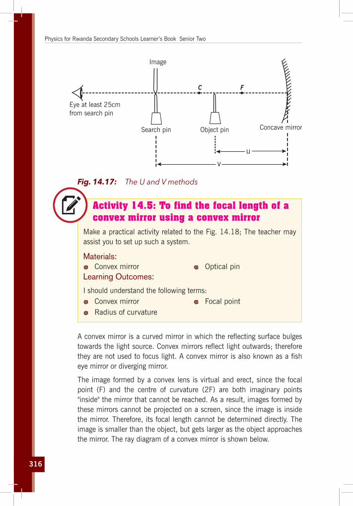
316
Physics for Rwanda Secondary Schools Learner’s Book Senior Two
Eye at least 25cmfrom search pin
Concave mirrorObject pin
Image
C F
Search pin
v
u
Fig. 14.17: The U and V methods
Activity 14.5: To find the focal length of a convex mirror using a convex mirror
Make a practical activity related to the Fig. 14.18; The teacher may assist you to set up such a system.
Materials: Convex mirror Optical pin
Learning Outcomes:
I should understand the following terms: Convex mirror Focal point Radius of curvature
A convex mirror is a curved mirror in which the reflecting surface bulges towards the light source. Convex mirrors reflect light outwards; therefore they are not used to focus light. A convex mirror is also known as a fish eye mirror or diverging mirror.
The image formed by a convex lens is virtual and erect, since the focal point (F) and the centre of curvature (2F) are both imaginary points "inside" the mirror that cannot be reached. As a result, images formed by these mirrors cannot be projected on a screen, since the image is inside the mirror. Therefore, its focal length cannot be determined directly. The image is smaller than the object, but gets larger as the object approaches the mirror. The ray diagram of a convex mirror is shown below.

317
Unit 14: Reflection of light in curved mirrors
Object
(Focus)
Image
Centre ofcurvature
Principal axis
2FF2F’ F’
Fig. 14.18: Measuring the focal length of a convex mirror
The focal length f of the convex mirror is calculated using the formula,
f = Radius of curvature2
= R2
14.5 Other types of curved mirrors
14.5.1 Parabolic mirrors A parabolic mirror (or parabolic reflector) has a reflective surface used to collect or project light. Its shape is that of a circular paraboloid, that is, the surface generated by a parabola revolving around its axis.
F F
Fig. 14.19: Parabolic mirrors
Any incoming ray that is parallel to the axis of the dish will be reflected to the focal point, or “focus”. Because light can be reflected in this way, parabolic reflectors can be used to collect and concentrate light entering the reflector at a particular angle. Similarly, light radiating from the “focus” to the dish can be transmitted outward in a beam that is parallel to the axis of the dish. In contrast with spherical reflectors, which suffer from a spherical aberration, the parabolic reflectors can be made to accommodate beams of any width. However, if the incoming beam makes

318
Physics for Rwanda Secondary Schools Learner’s Book Senior Two
a non-zero angle with the axis (or if the emitting point source is not placed in the focus), parabolic reflectors suffer from an aberration called coma.
The most common modern applications of the parabolic reflector are in satellite dishes, reflecting telescopes, and many lighting devices such as spotlights, car headlights etc.
14.5.2 The Ellipsoidal mirrorEllipsoidal mirrors have two conjugate foci (but in this case the focus is a geometric point commonly for any ellipsoid). Light from one focus passes through the other focus after reflection. Ellipsoids collect a much higher fraction of total emitted light than a spherical mirror or conventional lens system. The ellipsoidal mirror is the most efficient optics element of introducing the light that there was from one point into another point.
1F 2F
Fig. 14.20: The Ellipsoidal mirror
14.6 Unit 14 assessment
1. Consider the diagram at the right. Which one of the angles (A, B, C, or D) is the angle of incidence? ______which one of the angles is the angle of reflection? ______
Mirror
030
2. A ray of light is incident towards a plane mirror at an angle of 300 with the mirror surface. What will be the angle of reflection?

319
Unit 14: Reflection of light in curved mirrors
3. A ray of light is approaching a set of three mirrors as shown in the diagram. The light ray is approaching the first mirror at an angle of 450 with the mirror surface. Trace the path of the light ray as it bounces off the mirror. Continue tracing the ray until it finally exits from the mirror system. How many times will the ray reflect before it finally exits?
045
045045
4. Draw a ray diagram to show that a vertical mirror need not be 1.60m long in order that a woman 1.60m tall may see a full-length image of herself in it. If the man’s eyes are 10cm below the top of her head, find the shortest length of the mirror necessary and the length of its base above floor level.
5. A concave spherical mirror has a focal length of 10.0cm. Locate the image of a pencil that is placed upright 30.0cm from the mirror. a) Find the magnification of the image.
b) Draw a ray diagram to confirm your answer.
6. An upright pencil is placed 10.0cm from a convex spherical mirror with a focal length of 8.00cm. Find the position and the magnification of the image.
7. An object is placed (a) 20cm, (b) 4cm, infront of a concave mirror of focal length 12cm. Find the nature and the position of the image formed in each case.
8. A concave mirror produces a real image 1cm tall of an object 2.5mm tall placed 5cm from the mirror. Find the position of the image and the focal length of the mirror.
9. A convex mirror of focal length 18cm produces an image on its axis, 6cm away from the mirror. Calculate the position of the object.
10. A 1.5cm high diamond ring is placed 20.0cm from a concave mirror whose radius of curvature is 30.0cm. Determine: a) The position of the image, and its size.
b) Where the new image will be if the object is placed where the image is.

320
Physics for Rwanda Secondary Schools Learner’s Book Senior Two
11. An object of height h = 4cm is placed a distance p = 15cm infront of a concave mirror of focal length f = 20cm. a) What is the height, location, and nature of the image?
b) Suppose that the object is moved to a new position a distance p = 25cm infront of the mirror. What now is the height, location, and nature of the image?
12. A dental technician uses a small mirror that gives a magnification of 4.0 when it is held 0.60cm from a tooth. What is the radius of the curvature of the mirror?
13. A meter stick lies along the optical axis of a convex mirror of focal length 40cm, with its near end 60cm from the mirror surface. Five-centimeter toy figures stand erect on both the near and far ends of the meter stick.
VMeterstick F C
a) How long is the virtual image of the meter stick?
b) How tall are the toy figures in the image, and are they erect or inverted?
14. How far must an object be placed infront of a convex mirror of radius of curvature R = 50cm in order to ensure that the size of the image is ten times less than the size of the object? How far behind the mirror is the image located?

ElectronicsElectronic Devices

322

323
Unit15
Basic Electronic Components
Key unit competenceThe learner should be able to explain the working principle of basic electronic devices.
My goalsBy the end of this unit, I will be able to:
define an electronic device. identify symbols of electronic components. name different electronic components. outline the working principle of basic electronic devices. mention the importance of electronic devices in everyday life. appreciate the important role of electronic devices in life. demonstrate knowledge in analysing and modeling physical
processes.
Key concepts1. What do you understand by the term electronic?2. How can you differentiate electronics from electricity?3. Illustrate different electronic components.4. What is a motherboard?5. Describe different examples of electronic devices.
Vocabulary
Electronics, motherboard, forwarding bias, reverse bias, transistor, diode, capacitor, inductor, electronic devices.

324
Physics for Rwanda Secondary Schools Learner’s Book Senior Two
y Reading strategy
After you read each section, pay attention to the paragraphs that contain definitions of key terms. Use all the information to explain the key terms in your own words and make drawings of different electronic components and their functions and suggest different applications on motherboards.
15.1 Definition of electronics
Activity 15.1: Investigation about what electronics is.
Take a dictionary and discuss on the following key concepts. Electronics Electricity
Conductors Semi-conductors
Questions:1. Give the difference between electricity and electronics.2. Give the difference between conductors and semi-conductors.3. When listening to the radio, where do you think voices are
coming from?4. When watching a television where do you think images are
coming from and how are they coming on your television set?
Electronics is the branch of science that deals with the study of flow and control of electrons (electricity) and the study of their behaviour and effects in vacuums, gases, and semi-conductors, and with devices using such electrons. This control of electrons is accomplished by devices that resist, carry, select, steer, switch, store, manipulate, and exploit the electron.
In fact, Electronics is the branch of physics that deals with the emission and effects of electrons and with the use of electronic devices. Electronics refers to the flow of charge (moving electrons) through non-metal conductors; mainly semi-conductors, whereas electrical refers to the flow of charge through metal conductors. The Difference between Electronics and Electrical is that: Electronics deals with flow of charge (electron) through non-metal conductors (semi-conductors) while Electrical deals with the flow of charge through metal conductors.

325
Unit 15: Basic Electronic Components
Semi-conductor devices: This is a conductor made of semi-conducting material. Semi-conductors are made up of a substance with electrical properties intermediate between a good conductor and a good insulator. A semi-conductor device conducts electricity poorly at room temperature, but has increasing conductivity at higher temperatures. Metalloids are usually good semi-conductors.
Example: Flow of charge through silicon which is not a metal would come under electronics whereas flow of charge through copper which is a metal would come under electrical.
15.2 Illustration of standard symbols of some electronic components
Activity 15.2: Identifying the electronic devices
Use the provided devices in Figures 15.1 and 15.2 to answer the following questions.
a) b)
d)c)
Fig. 15.1: Some electronic devices
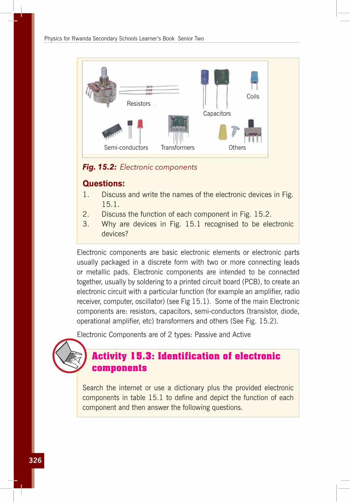
326
Physics for Rwanda Secondary Schools Learner’s Book Senior Two
Semi-conductors
Resistors
Capacitors
Coils
OthersTransformers
Fig. 15.2: Electronic components
Questions:1. Discuss and write the names of the electronic devices in Fig.
15.1.2. Discuss the function of each component in Fig. 15.2.3. Why are devices in Fig. 15.1 recognised to be electronic
devices?
Electronic components are basic electronic elements or electronic parts usually packaged in a discrete form with two or more connecting leads or metallic pads. Electronic components are intended to be connected together, usually by soldering to a printed circuit board (PCB), to create an electronic circuit with a particular function (for example an amplifier, radio receiver, computer, oscillator) (see Fig 15.1). Some of the main Electronic components are: resistors, capacitors, semi-conductors (transistor, diode, operational amplifier, etc) transformers and others (See Fig. 15.2).
Electronic Components are of 2 types: Passive and Active
Activity 15.3: Identification of electronic components
Search the internet or use a dictionary plus the provided electronic components in table 15.1 to define and depict the function of each component and then answer the following questions.

327
Unit 15: Basic Electronic Components
Materials:Motherboard of an electronic device (such as a radio receiver)
Questions:1. Identify and list down the components that are on the
motherboard.2. Draw their symbols and comment on them.3. Write down in two columns, which ones are passive and
which ones are active electronic devices.4. Take any motherboard to find and identify its electronic
components.
Passive electronic components are those that do not have gain or directionality. They are also called Electrical elements or electrical components. E.g. resistors, capacitors, diodes, inductors.
Active electronic components are those that have gain or directionality. E.g. transistors
Here are some of the Electronic Components and their functions in electronics and electrical (Table 15.1 below):
Table 15.1: Electronic component
Name Image Symbol Functions
1. Terminals and Connectors
Barrel Jack2×3-Pin
connector6-Pin connector
J3
JP1
J1 Components to make an electrical connection.
2. Resistors Components used to resist current.
3. Switches or
Figure A Figure B
Components that may be made to either conduct (closed) or not (open).

328
Physics for Rwanda Secondary Schools Learner’s Book Senior Two
Name Image Symbol Functions
4. Capacitors Components that store electrical charge in an electrical field.
5. Magnetic or Inductive Components
INDUCTORcylindrical
These are Electrical components that use magnetism
6. Ordinary Diodes
Anode(+)
Cathode(–) or
Light Emitting Diode-LED
Zener Diode
Power Diode
Signal Diode
CathodeAnode
Components that conduct electricity in only one direction.
7. Zener diode Anode Cathode A Zener diode allows current to flow from its anode to its cathode like a normal semi-conductor diode, but it also permits current to flow in the reverse direction when its “Zener voltage” is reached.
8. Transistors or
Emitter Emitter
Emitter
Emitterp pn
CollectorCollector
Collector Collector
PNP NPN
Base
Base Base
Base
n npA semi-conductor device capable of amplification
9. Integrated Circuits or ICs: A
IC Symbols
A Microelectronic computer circuit incorporated into a chip or semi-conductor; a whole system rather than a single component.
15.2.1 Electronic component name acronymsElectronic Component Name Acronyms: Here is a list of Electronic Component name abbreviations widely used in the electronics industry:

329
Unit 15: Basic Electronic Components
· AE: Aerial, antenna · B: Battery · BR: Bridge rectifier · C: Capacitor · CRT: Cathode ray tube
· LCD: Liquid crystal display · LDR: Light dependent resistor · LED: Light emitting diode · LS: Speaker · M: Motor · MCB: Circuit breaker
· D or CR: Diode · F: Fuse · GDT: Gas discharge tube · IC: Integrated circuit · J: Wire link
· Mic: Microphone · Ne: Neon lamp · OP: Operational Amplifier · JFET: Junction gate field-effect transistor · L: Inductor
15.3 Electronic components on a motherboard
Activity 15.4: Identifying electronic components on a motherboard
Take the mother board of a radio receiver and try to identify the different electronic components in Fig. 15.3.
Fig. 15.3: Motherboard
Alternatively referred to as the mb, mainboard, mobo, mobd, backplane board, base board, main circuit board, planar board, system board, or a logic board on Apple computers, the motherboard is a printed circuit board that is the foundation of any electronic device. For a computer, it is located at the bottom of the computer case. It allocates power to the CPU, RAM, and all other computer hardware components. Most importantly,

330
Physics for Rwanda Secondary Schools Learner’s Book Senior Two
the motherboard allows hardware components to communicate with one another.
15.3.1 Ordinary diode
Activity 15.5: Different types of diodes
Using a dictionary and the internet, plus the provided diodes in Fig 15.4, define and depict the function of each type of diode and answer the following questions.
Materials:Motherboard of an electronic device (such as a computer).
Questions:1. Write down the application of each type of diode.2. Take any motherboard to find and identify different types of
diodes on it.
Signal diode
Zener diodes
Light emitting diodes
IR LEDs
Shottkey diode
Shockley diode
Photodiodes transient voltage supression diodes
super barrier diode
step recovery diodes
peltier diodes
vaccum diode
vaccum diode
PIN diodesvaractor diodestunnel diodes
gunn diodes crystal diode avalanche diode
LASER diodes
point contact diode
silicon controlled rectiner
Constant current diode
Fig. 15.4: Types of diodes

331
Unit 15: Basic Electronic Components
In electronics, a diode is a two-terminal electronic component that conducts primarily in one direction (asymmetric conductance); it has low (ideally zero) resistance to the flow of current in one direction, and high (ideally infinite) resistance in the other. A semi-conductor diode, the most common type today, is a crystalline piece of semi-conductor material with a p–n junction connected to two electrical terminals. A vacuum tube diode has two electrodes, a plate (anode) and a heated cathode. Semi-conductor diodes were the first semi-conductor electronic devices.
15.4 Current–voltage characteristic
1
0
5
10
15
20
25
30
0-1-49-50-51-52V (v)
I (m
A)
Breakdown ForwardReverse
V
I
brV sIdV
Fig. 15.5: I–V (current vs. voltage) characteristics of a p–n junction diode
A semi-conductor diode’s behaviour in a circuit is given by its current–voltage characteristic, or I–V graph (Fig. 15.5). The shape of the curve is determined by the transport of charge carriers through the so-called depletion layer or depletion region that exists at the p–n junction between differing semi-conductors. When a p–n junction is first created, conduction-band (mobile) electrons from the N-doped region diffuse into the P-doped region where there is a large population of holes (vacant places for electrons) with which the electrons “recombine”.
15.4.1 Forwarding and reverse biasing If an external voltage is placed across the diode with the same polarity as the built-in potential, the depletion zone continues to act as an insulator, preventing any significant electric current flow (unless electron–hole pairs

332
Physics for Rwanda Secondary Schools Learner’s Book Senior Two
are actively being created in the junction by, for instance, light (LEDs); this is called the reverse bias phenomenon. However, if the polarity of the external voltage opposes the built-in potential, recombination can once again proceed, resulting in a substantial electric current through the p–n junction (i.e. substantial numbers of electrons and holes recombine at the junction). Thus, if an external voltage greater than and opposite to the built-in voltage is applied, a current will flow and the diode is said to be “turned on” as it has been given an external forward bias. The diode is commonly said to have a forward “threshold” voltage, above which it conducts and below which conduction stops. However, this is only an approximation as the forward characteristic is according to the Shockley equation absolutely smooth (see Fig. 15.7)
15.4.2 Rectifications
Activity 15.6: Defining rectifier
Use a dictionary and search the internet to identify the meaning of rectifier and its function.
MaterialsA telephone charger
An AC to DC converter
Procedure:Open the charger and identify the component of the motherboard inside it.
Question:1. When charging a phone why does it require a specific
charger plug?2. Describe and explain different components found on that
motherboard.3. Discuss and comment on the importance of rectifiers.

333
Unit 15: Basic Electronic Components
in out
++
+
+
+
––
–
–
–
AC In AC In
a)DC Out DC Out
A B
Fig. 15.6: Halfwaverectifierandfullwaverectifier
The non-symmetric behaviour is due to the detailed properties of the p-n junction. The diode acts like a one-way valve for current and this is a very useful characteristic. One application is to convert alternating current (AC), which changes polarity periodically, into direct current (DC), which always has the same polarity. Normal household power is AC while batteries provide DC; and converting from AC to DC is called rectification. Diodes are used so commonly for this purpose that they are sometimes called rectifiers, although there are other types of rectifying devices. Fig. 15.6 (a) shows the input and output current for a simple half-wave rectifier. The circuit gets its name from the fact that the output is just the positive half of the input waveform.
Fig. 15.6 (b) shows a full-wave rectifier circuit which uses four diodes arranged so that both polarities of the input waveform can be used at the output. The full-wave circuit is more efficient than the half-wave one.
15.4.3 Zener Diode
Fig. 15.7: Zener diode and its symbol
A Zener diode (Fig. 15.7) allows current to flow from its anode to its cathode like a normal semi-conductor diode, but it also permits current to flow in the reverse direction when its “Zener voltage” is reached. Zener diodes have a highly doped, p-n junction. Normal diodes will also break

334
Physics for Rwanda Secondary Schools Learner’s Book Senior Two
down with a reverse voltage but the voltage and sharpness of the knee are not as well defined as for a Zener diode. Also normal diodes are not designed to operate in the breakdown region, but Zener diodes can reliably operate in this region.
Operation (voltage regulator)Consider the current-voltage characteristic of a Zener diode with a breakdown voltage of 17 volts. Notice the change of voltage scale between the forward biased (positive) direction and the reverse biased (negative) direction, as shown in the Fig. 15.8 below.
U=0,65V
U=17,1V
1=1mA .....................
U
I
Fig. 15.8: I-V curve for Zener diode
A conventional solid-state diode allows significant current if it is reverse-biased above its reverse breakdown voltage. When the reverse bias breakdown voltage is exceeded, a conventional diode is subject to high current due to avalanche breakdown. Unless this current is limited by circuitry, the diode may be permanently damaged due to overheating. A Zener diode exhibits almost the same properties, except the device is specially designed so as to have a reduced breakdown voltage, the so-called Zener voltage. By contrast with the conventional device, a reverse-biased Zener diode exhibits a controlled breakdown and allows the current to keep the voltage across the Zener diode close to the Zener breakdown voltage. For example, a diode with a Zener breakdown voltage of 3.2V exhibits a voltage drop of nearly 3.2V across a wide range of reverse currents. The Zener diode is therefore ideal for applications such as the generation of a reference voltage (e.g. for an amplifier stage), or as a voltage stabilizer for low-current applications.
335
Unit 15: Basic Electronic Components
15.4.6 Transistors
Activity 15.7: Identifying a transistor
MaterialsMotherboard of a radio receiver
Procedure:Identify transistors from the motherboard among many electronic components on it.
Question:1. According to its position, try to discern its function there.2. Where else in other components is a transistor useful?3. Comment and discuss the further use of a transistor.
A transistor is a semi-conductor device used to amplify or switch electronic signals and electrical power. It is composed of semi-conductor material with at least three terminals for connection to an external circuit. A voltage or current applied to one pair of the transistor’s terminals changes the current through another pair of terminals. Because the controlled (output) power can be higher than the controlling (input) power, a transistor can amplify a signal. Today, some transistors are packaged individually, but many more are found embedded in integrated circuits.
Simplified operationThe essential usefulness of a transistor comes from its ability to use a small signal applied between one pair of its terminals to control a much larger signal at another pair of terminals. This property is called gain. It can produce a stronger output signal, a voltage or current, which is proportional to a weaker input signal; that is, it can act as an amplifier. Alternatively, the transistor can be used to turn current on or off in a circuit as an electrically controlled switch, where the amount of current is determined by other circuit elements.
There are two types of transistors, which have slight differences in how they are used in a circuit. A bipolar transistor has terminals labeled base, collector, and emitter.

336
Physics for Rwanda Secondary Schools Learner’s Book Senior Two
A small current at the base terminal (that is, flowing between the base and the emitter) can control or switch a much larger current between the collector and emitter terminals. For a field-effect transistor, the terminals are labeled gate, source, and drain, and a voltage at the gate can control a current between source and drain.
Transistor as an amplifier
outV
inV
+V
CR1R
2RER
outC
EC
E
CB
inC
The common-emitter amplifier is designed so that a small change in voltage (Vin) changes the small current through the base of the transistor; the transistor’s current amplification combined with the properties of the circuit mean that small swings in Vin produce large changes in Vout.
Various configurations of a single transistor amplifier are possible, with some providing current gain, some voltage gain, and some both.
Fig. 15.9: Amplifiercircuit,common-emitterconfigurationwithavoltage-divider bias circuit
Modern transistor audio amplifiers of up to a few hundred watts are common and relatively inexpensive.
15.5 An example of electronic devices
Activity 15.8: Visiting an Electronic repair workshop
Use any available computer or phone visit a computer or phone repair workshops to identify different components of a telephone and computer.
Question:Discuss and explain the components such as diodes, resistors, capacitors, transistors and the function of:1. A telephone.2. A computer.3. A radio receiver.

337
Unit 15: Basic Electronic Components
15.6.1 Mobile phone
Fig. 15.10: Mobile phone motherboard
All mobile phones have a number of features in common, but manufacturers also try to differentiate their own products by implementing additional functions to make them more attractive to consumers. This has led to great innovation in mobile phone development over the past 20 years.
15.5.2 ComputersThe motherboard is the main component of a computer. It is a large rectangular board with integrated circuitry that connects the other parts of the computer including the CPU, the RAM, the disk drives (CD, DVD, hard disk, or any others) as well as any peripherals connected via the ports or the expansion slots.
Components directly attached to or part of the motherboard include:
The CPU (Central Processing Unit), which performs most of the calculations which enable a computer to function, and is sometimes referred to as the brain of the computer. It is usually cooled by a heatsink and fan, or water-cooling system. Most newer CPUs include an on-die Graphics Processing Unit (GPU). The clock speed of CPUs governs how fast it executes instructions, and is measured in GHz; typical values lie between 1 GHz and 5 GHz. Many modern computers have the option to overclock the CPU which enhances

338
Physics for Rwanda Secondary Schools Learner’s Book Senior Two
performance at the expense of greater thermal output and thus a need for improved cooling.
The chipset, which includes the north bridge, mediates communication between the CPU and the other components of the system, including main memory.
Random-Access Memory (RAM), which stores the code and data that are being actively accessed by the CPU. RAM usually comes on DIMMs in the sizes 2GB, 4GB, and 8GB, but can be much larger.
Read-Only Memory (ROM), which stores the BIOS that runs when the computer is powered on or otherwise begins execution, a process known as Bootstrapping, or “booting” or “booting up.” The BIOS (Basic Input Output System) includes boot firmware and power management firmware. Newer motherboards use Unified Extensible Firmware Interface (UEFI) instead of BIOS.
Buses connect the CPU to various internal components and to expand cards for graphics and sound.
The CMOS battery, which powers the memory for date and time in the BIOS chip. This battery is generally a watch battery.
The video card (also known as the graphics card), which processes computer graphics. More powerful graphics cards are better suited to handle strenuous tasks, such as playing intensive video games.
15.5.3 Watches
Activity 15.9: Identifying the component of a digital watch
Take a digital wrist watch as in Fig. 15.11 and open it to see components inside on the motherboard. Discuss and explain functions of different components you have observed on the motherboard.

339
Unit 15: Basic Electronic Components
A quartz watch is a watch that uses an electronic oscillator that is regulated by a quartz crystal to keep time. An electronic oscillator is an electronic circuit that produces a periodic, oscillating electronic signal, often a sine wave or a square wave. They are widely used in many electronic devices.
Fig. 15.11: Electronic digital watch
Common examples of signals generated by oscillators include signals broadcast by radio and television transmitters, clock signals that regulate computers and quartz watches, and the sounds produced by electronic beepers. This crystal oscillator creates a signal with very precise frequency, so that quartz clocks are at least an order of magnitude more accurate than mechanical clocks.
15.6 Working principle of basic electronic devices
Principles of Electronics presents a broad spectrum of topics, such as atomic structure, Kirchhoff’s laws, energy, power, introductory circuit analysis techniques, Thevenin’s theorem, the maximum power transfer theorem, electric circuit analysis, magnetism, resonance, control relays, relay logic, semi-conductor diodes, electron current flow, and much more. Smoothly integrate the flow of material in a non-mathematical format without sacrificing depth of coverage or accuracy to help readers grasp more complex concepts and gain a more thorough understanding of the principles of electronics. This includes many practical applications, problems and examples emphasising troubleshooting, design, and safety to provide a solid foundation in the field of electronics.
In general, troubleshooting is the identification of the diagnosis of “trouble” in the management flow of a corporation or a system caused by a failure of some kind. The problem is initially described as symptoms of malfunction; and troubleshooting is the process of determining and remedying the causes of these symptoms.

340
Physics for Rwanda Secondary Schools Learner’s Book Senior Two
A system can be described in terms of its expected, desired or intended behaviour (usually, for artificial systems, its purpose). Events or inputs to the system are expected to generate specific results or outputs. (For example selecting the “print” option from various computer applications is intended to result in a hardcopy emerging from some specific device). Any unexpected or undesirable behaviour is a symptom. Troubleshooting is the process of isolating the specific cause or causes of the symptom. Frequently the symptom is a failure of the product or process to produce any results (nothing was printed, for example). Corrective action can then be taken to prevent further failures of a similar kind.
15.7 Unit 15 assessment
1. A semi-conductor is formed by ……… bonds.A. CovalentB. ElectrovalentC. Co-ordinateD. None of the above
2. A semi-conductor has …………. temperature coefficient of resistance.A. PositiveB. ZeroC. NegativeD. None of the above
3. The most commonly used semi-conductor is ………..A. GermaniumB. SiliconC. CarbonD. Sulphur
4. A semi-conductor has generally ……………… valence electrons.A. 2B. 3C. 6D. 4
5. When a pure semi-conductor is heated, its resistance ………….. A. Goes upB. Goes downC. Remains the sameD. Can’t say

341
Unit 15: Basic Electronic Components
6. Addition of pentavalent impurity to a semi-conductor creates many ……..A. Free electronsB. HolesC. Valence electronsD. Bound electrons
7. A pentavalent impurity has ………. Valence electrons.A. 3B. 5C. 4D. 6
8. Addition of trivalent impurity to a semi-conductor creates many ……...........................A. Holes
B. Free electrons
C. Valence electrons
D. Bound electrons
9. A hole in a semi-conductor is defined as …………….A. A free electron
B. The incomplete part of an electron pair bond
C. A free proton
D. A free neutron
10. In a semi-conductor, current conduction is due to ……..A. Only holes
B. Only free electrons
C. Holes and free electrons
D. None of the above
11. What is the basis for classifying a material as a conductor, semi-conductor?
12. Differentiate semi-conductors, conductors and insulators on the basis of band gap.
13. Is a hole a fundamental particle in an atom?
14. Define a hole in a semi-conductor.
15. Why is it that silicon and germanium are the two widely used semi-conductor materials?

342
16. Which of the two semi-conductor materials Si or Ge has larger conductivity at room temperature? Why?
17. Why does a pure semi-conductor behave like an insulator at absolute zero temperature?
18. What is the main factor for controlling the thermal generation and recombination?
19. In which bands do the movement of electrons and holes take place?
20. Discuss the mechanism by which conduction takes place inside the semi-conductor?

343
Hypertext book1. htt://www.mkpublishers.com2. http://en.wikibooks.org/w/index.php?title=Physics_Exercises/
Kinematics3. http://en.wikipedia.org/wiki/Newton%27s_laws_of_motion4. http://fr.wikipedia.org/wiki/kinemarics5. http://fr.wikipedia.org/wiki/phys#Recherche-d6. http://pstc.aapt.org7. http://www.answers.com/Topic/Physics8. http://www.answers.com/topic/temperature-conversion9. http://www.answers.com/Topic/Thermometer10. http://www.glenbrook.k12.il.us/GBSSCI/PHYS/Class/newtlaws11. Http://www.howstuffworks.com/pulley.htm 12. http://www.newworldencyclopedia.org/entry/Freezing_point13. http://www.school-for-champions.com/science/matterstates 14. www.iop.org15. www.physicscetral.com16. www.sciam.com17. www.worldofteaching.com 18. http://www.dynamicscience.com.au/tester/solutions1/chemistry/
atomic%20structure/ 19. https://www.boundless.com/physics/textbooks/boundless-
physics-textbook20. http://www.electronicsandyou.com/index.html#sthash.
ZoDTLzgP.dpuf

344
Bibliography
1. ABBOT A.F, JOHN COCKCROFT, 1989, Physics, Fifth Edition, Heinemann Educational Publishers.
2. Cunningham, William P, 2001, Environmental science, Mc Graw-Hill, 6th Ed.
3. HEWITT P.G, SUCH0CKI J., HEWITT L.A., 1999, Conceptual Physical Science, Second edition, Addison Wesley Longman
4. Holt, Rinehart and Winstone, 1999, Physics5. MINEDUC, 2006, Ordinary level science curriculum (Biology,
Chemistry, Physics), NCDC, Kigali, 6. PATRICK T., 2004, Mathematics standard level, 3rd Edition,
Ibid Press, Victoria, 7. SILVER Burdett, GINN Inc, 1990, Physical Science, United
States of America, 8. WABWIRE S.H, KASIRYE S., 2007, MK secondary Physics,
student’s book 1, MK Publishers LTD, Kampala-Uganda.