Practical physics
518
Handle with EXTREME CAR This volume is damaged or brittl and CANNOTbe repaired! photocopy only if necest return to staff do not put in bookdrop Gerstein Science Information Centre Glazebrook, Richard Sir Practical Physics OLD CLASS Physics G c.l PASC
-
Upload
khangminh22 -
Category
Documents
-
view
0 -
download
0
Transcript of Practical physics
Handle with
EXTREME CARThis volume is damaged or brittl
and CANNOTbe repaired!
photocopy only if necestreturn to staff
do not put in bookdropGerstein Science Information Centre
Glazebrook, Richard Sir
Practical Physics
OLD CLASS
PhysicsGc.l
PASC
TEXT-BOOKS OF SCIENCE,MECHANICAL AND PHYSICAL.
PHOTOGRAPHY. By Captain W. DE\VIVELESLIE ABNEY,C.B. F.R.S. late Instructor in Chemistry and Photography at the Schoolof Military Engineering, Chatham. With 105 Woodcuts. Price 3$. 6d.
The STRENGTH of MATERIALS and STRUG-TURKS : the Strength of Materials as depending on their quality and as
ascertained by Testing Apparatus ; the Strength of Structures, as dependingon their form and arrangement, and on the materials of which they are com-
posed. By Sir J. ANDERSON, C.E. &c. With 66 Woodcuts. Price 3*. 6d.
INTRODUCTION to the STUDY of ORGANICCHEMISTRY; the CHEMISTRY ofCARBON and its COMPOUNDS.By HENRY E. ARMSTRONG, Ph.D. F.R.S. With 8 Woodcuts. Price 3 s. >d.
ELEMENTS ofASTRONOMY. By Sir R. S. BALL, LL. D.F.R.S. Andrews Professor of Astronomy in the Univ. of Dublin, RoyalAstronomer of Ireland. With 136 Woodcuts. Price 6s.
RAILWAY APPLIANCES. A Description of Details of
Railway Construction subsequent to the completion of Earthworks andStructures, including a short Notice of Railway Rolling Stock. By JOHNWOLFE BARRY, M.I.C.E. With 207 Woodcuts. Price 3*. 6</.
SYSTEMATIC MINERALOGY. By HILARY BAUER-MAN, F.G.S. Associate of the Royal School of Mines. With 373 Woodcuts.Price 6s.
DESCRIPTIVE MINERALOGY. By HILARY BAUER-MAN, F.G.S. &c. With 236 Woodcuts. Price 6s.
METALS, their PROPERTIES and TREATMENT.By C. L. BLOXAM and A. K. HUNTINGTON, Professors in King's College,London. With 130 Woodcuts. Price 55.
PRACTICAL PHYSICS. By R. T. GLAZEBROOK, M.A.F.R.S. and W. N. SHAW, M. A. With 80 Woodcuts. Price 6*.
PHYSICAL OPTICS. By R. T. GLAZEBROOK, M.A.F.R.S. Fellow and Lecturer of Trin. Coll. Demonstrator of Physics at theCavendish Laboratory, Cambridge. With 183 Woodcuts. Price 6s.
The ART ofELECTRO-METALLURGY, including all
known Processes of Electro-Deposition. By G. GORE, LL.D. F.R.S.With 56 Woodcuts. Price 6*.
ALGEBRA and TRIGONOMETRY. By WILLIAMNATHANIEL GRIFFIN, B.D. Price 35. 6<t. NOTES ON, with SOLUTIONS of the more difficult QUESTIONS. Price 3*. 6d.
THE STEAM ENGINE. By GEORGE C. V. HOLMES,Whitworth Scholar ; Secretary of the Institution of Naval Architects. With212 Woodcuts. Price 6j.
-x_'\x\yx^wxx^>^^vy-
London : LONGMANS, GREEN, & CO.
Text-Books of Science..
ELECTRICITY and MAGNETISM. By FLEEMINGJsNKiN.F.R.SS.L. & E. late Professor of Engineering in the University of
Edinburgh. With 177 Woodcuts. Price y. 6d.
THEORY of HEAT. By J. CLERK MAXWELL, M.A. LL.D.Edin. F.R.SS. L. & E. With 41 Woodcuts. Price 3*. 6d.
TECHNICAL ARITHMETIC and MENSURA-TION. By CHARLES W. MERRIFIHLD, F.R.S. Price 3*. 6d. KEY, bythe Rev. JOHN HUNTER, M.A. Price 3$. 6d.
INTRODUCTION to the STUDY of INORGANICCHEMISTRY. By WILLIAM ALLEN MILLER, M.D. LL:D. F.R.S. With72 Woodcuts. Price 3^. >d.
TELEGRAPHY. By W. H. PREECE, F.R.S. M.I.C.E. and
J. SIVEWKIGHT, M.A. C.M.G. With 160 Woodcuts. Price 55.
The STUDY of ROCKS, an ELEMENTARY Text-Book of PETROLOGY. By FRANK RUTLEY, F.G.S. of Her Majesty'sGeological Survey With 6 Plates and 88 Woodcuts. Price 4*. 6d.
WORKSHOP APPLIANCES, including Descriptions ofsome of the Gauging and Measuring Instruments Hand-Cutting Tools,Lathes, Drilling, Planing, and other Machine Tools used by Engineers.By C. P. B. SHELLEY, M.I.C.E. With 291 Woodcuts. Price 4*. 6d.
STRUCTURAL and PHYSIOLOGICAL BOTANY.By Dr. OTTO WILHELM THOME", Rector of the High School, Cologne, andA. W. BENNETT. M.A. B.Sc. F.L.S. With 600 Woodcuts and aColoured Map. Price 6s.
QUANTITATIVE CHEMICAL ANALYSIS. By T.E. THORPE, F.R.S. Ph.D. Professor of Chemistry in the AndersonianUniversity, Glasgow. With 88 Woodcuts. Price 4*. 6d.
QUALITATIVE ANALYSIS and LABORATORYI'KACTICK. P.y T. K. TH..KI-K, Ph.D. F.R.S. Professor of Chemistryin the Andersonian University, Glasgow, and M. M. I'AITISMM MIMK,M.A. and F. U.S. K. With Plate of Spectra and 57 Woodcuts. Price 35. 6<f.
INTRODUCTION to the STUDY of CHEMICALPHILOSOPHY; the PRINCIPLES of THEORETICAL and SYSTE-MAT1CAL CHEMISTRY. By WILLIAM A. TILDEN. D.Sc. London.F.R.S. With 5 Woodcuts. With or without Answers to Problems, 45. 6d.
ELEMENTS of MACHINE DESIGN; an Introductionto the Principles which determine the Arrangement and Proportion of the
of Machines, and a Collection of Rules for Machine Design .
'
CAWTHOKNE UNWIN, B.Sc. M.I.C.E. With 325 Woodcuts. Price 6s.
PLANE and SOLID GEOMETRY. Uy II. W. WATSON,: !y Fellow of Trinity College, Cambridge. Price 3*. 6d.
London : LONGMANS, GREEN, & CO.
TEXT-BOOKS OF SCIENCE
ADAPTED FOR THE USE OF
ARTISANS AND STUDENTS IN PUBLIC AND SCIENCE SCHOOLS
PRACTICAL PHYSICS
PRINTED BY
SPOTTIS\VOODE AND CO., NEW-STREET SQUARE
LONDON

mi (2)
zCO
m0)
Q
/PRACTICAL PHYSICS
BY
R. T. GLAZEBROOK, M.A., F.R S S.
FELLOW OF TRINITY COLLEGE, AND
W. N. SHAW, M.A.FELLOW OF EMMANUEL COLLEGE
Demonstrators at the Cavendish Lcei'oratory, Cambridge
THIRD EDITION
LONDON
LONGMANS, GREEN, AND COAND NEW YORK : 15 EAST 16"' STREET
1889
Been *
,< ii - 1
PREFACE.
THIS book is intended for the assistance of Students and
Teachers in Physical Laboratories. The absence of any
book covering the same ground made it necessary for us, in
conducting the large elementary classes in Practical Physics
at the Cavendish Laboratory, to write out in MS. books the
practical details of the different experiments. The increase
in the number of well-equipped Physical Laboratories has
doubtless placed many teachers in the same position as we
ourselves were in before these books were compiled ;we
have therefore collected together the manuscript notes in
the present volume, and have added such general explana-
tions as seemed necessary.
In offering these descriptions of experiments for publica-
tion we are met at the outset by a difficulty which may
prove serious. The descriptions, in order to be precise,
must refer to particular forms of instruments, and may there-
fore be to a certain extent inapplicable to other instruments
of the same kind but with some difference, perhaps in the
arrangement for adjustment, perhaps in the method of
graduation. Spherometers, spectrometers, and katheto-
meters are instruments with which this difficulty is particu-
larly likely to occur. With considerable diffidence we have
thought it best to adhere to the precise descriptions referring
viii Preface.
to instruments in use in our own Laboratory, trusting that
the necessity for adaptation to corresponding instruments
used elsewhere will not seriously impair the usefulness of
the book. Many of the experiments, however, which we have
selected for description require only very simple apparatus,
a good deal of which has in our case been constructed in
the Laboratory itself. We owe much to Mr. G. Gordon,
the Mechanical Assistant at the Cavendish Laboratory, for
his ingenuity and skill in this respect.
Our general aim in the book has been to place before
the reader a description of a course of experiments which
shall not only enable him to obtain a practical acquaintance
with methods of measurement, but also as far as possible
illustrate the more important principles of the various sub-
jects. We have not as a rule attempted verbal explanations
of the principles, but have trusted to the ordinary physical
text-books to supply the theoretical parts necessary for
understanding the subject ;but whenever we have not been
able to call to mind passages in the text-books sufficiently
explicit to serve as introductions to the actual measurements,
we have either given references to standard works or have
endeavoured to supply the necessary information, so that a
student might not be asked to attempt an experiment without
at least being in a position to find a satisfactory explanation
of its method and principles. In following out this plan we
have found it necessary to interpolate a considerable amount
of more theoretical information. The theory of the balance
has been given in a more complete form than is usual in
mechanical text-books;the introductions1
to the measure-
ment of fluid pressure, thermometry, and calorimetry have
been inserted in order to accentuate certain important prac-
tical points which, as a rule, are only briefly touched upon ;
Preface. ix
while the chapter on hygrometry is intended as a complete
elementary account of the subject. We have, moreover,
found it necessary to adopt an entirely different style in
those chapters which treat of magnetism and electricity.
These subjects, regarded from the point of view of the
practical measurement of magnetic and electric quantities,
present a somewhat different aspect from that generally
taken. We have accordingly given an outline of the general
theory of these subjects as developed on the lines indicated
by the electro-magnetic system of measurement, and the
arrangement of the experiments is intended, as far as possi-
ble, to illustrate the successive steps in the development.
The limits of the space at our disposal have compelled
us to be as concise as possible ;we have, therefore, been
unable to illustrate the theory as amply as we could have
wished. We hope, however, that we have been suc-
cessful in the endeavour to avoid sacrificing clearness to
brevity.
We have made no attempt to give anything like a com-
plete list of the experiments that may be performed with
the apparatus that is at the present day regarded as the
ordinary equipment of a Physical Laboratory. We have
selected a few in our judgment the most typical experi-
ments in each subject, and our aim has been to enable the
student to make use of his practical work to obtain a clearer
and more real insight into the principles of the subjects.
\Vith but few exceptions, the experiments selected are of an
elementary character; they include those which have formed
for the past three years our course of practical physics for
the students preparing for the first part of the Natural
Sciences Tripos ;to these we have now added some ex-
periments on acoustics, on the measurement of wave-lengths,
x Preface.
and on polarisation and colours. Most of the students
have found it possible to acquire familiarity with the contents
of such a course during a period of instruction lasting over
two academical terms.
The manner in which the subjects are divided requires
perhaps a word of explanation. In conducting a class in-
cluding a large number of 'students, it is essential that a
teacher should know how many different students he can
accommodate at once. This is evidently determined by
the number of independent groups of apparatus which the
Laboratory can furnish. It is, of course, not unusual for an
instrument, such as a spectrometer, an optical bench, or
Wheatstone bridge, to be capable of arrangement for working
a considerable number of different experiments ;but this is
evidently of no assistance when the simultaneous accommo-
dation of a number of students is aimed at. For practical
teaching purposes, therefore, it is an obvious advantage to
divide the subject with direct reference to the apparatus
required for performing the different experiments. We have
endeavoured to carry out this idea by dividing the chapters
into what, for want of a more suitable name, we have called
'
sections,' which are numbered continuously throughout the
book, and are indicated by black type headings. Each
section requires a certain group of apparatus, and the teacher
knows that that apparatus is not further available when he has
assigned the section to a particular student. The different
experiments for which the same apparatus can be employed
are grouped together in the same section, and indicated by
italic headings.
The proof-sheets of the book have been in use during
the past year, in the place of the original MS. books, in the
following manner: The sheets, divided into the section.*
Preface. xi
above mentioned, have been pasted into MS. books, the re-
maining pages being available for entering the results obtained
by the students. The apparatus referred to in each book is
grouped together on one of the several tables in one large
room. The students are generally arranged in pairs, and be-
fore each day's work the demonstrator in charge assigns to
each pair of students one experiment that is, one section of
the book. A list shewing the names of the students and the
experiment assigned to each is hung up in the Laboratory,
so that each member of the class can know the section at
which he is to work. He is then set before the necessary
apparatus with the MS. book to assist him;
if he meets
with any difficulty it is explained by the demonstrator in
charge. The results are entered in the books in the form
indicated for the several experiments. After the class is
over the books are collected and the entries examined by
the demonstrators. If the results and working are correct
a new section is assigned to the student for the next time;
if they are not so, a note of the fact is made in the class
list, and the student's attention called to it, and, if necessary,
he repeats the experiment. The list of sections assigned to
the different students is now completed early in the day
before that on which the class meets, and it is hoped that the
publication of the description of the experiment will enable
the student to make himself acquainted beforehand with the
details of his day's work.
Adopting this plan, we have found that two demon-
strators can efficiently manage two classes on the same day,
one in the morning, the other in the afternoon, each con-
taining from twenty-five to thirty students. The students
have hitherto been usually grouped in pairs, in consequenceof the want of space and apparatus. Although this plan
xii Preface.
has some advantages, it is, we think, on the whole, undesir-
able.
We have given a form for entering results at the end of
each section, as we have found it an extremely convenient,
if not indispensable, arrangement in our own case. The
numerical results appended as examples are taken, with
very few exceptions, from the MS. books referred to above.
They may be found useful, as indicating the degree of
accuracy that is to be expected from the various experi-
mental methods by which they are obtained.
In compiling a book which is mainly the result of Labora-
tory experience, the authors are indebted to friends and
fellow-workers even to an extent beyond their own knowledge.
We would gladly acknowledge a large number of valuable
hints and suggestions. Many of the useful contrivances that
facilitate the general success of a Laboratory in which a large
class works, we owe to the Physical Laboratory of Berlin ;
some of them we have described in the pages that follow.
. For a number of valuable suggestions and ideas we are
especially indebted to the kindness of Lord Rayleigh, who
has also in many other ways afforded us facilities for the
development of the plans and methods of teaching explained
above. Mr. J. H. Rand ell, of Pembroke College, and Mr.
H. M. Elder, of Trinity College, have placed us under an
obligation, which we are glad to acknowledge, by reading
the proof-sheets while the work was passing through the
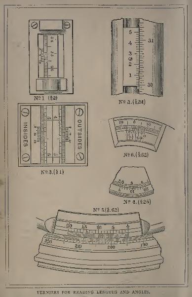
press. Mr. Elder has also kindly assisted us by photograph-
ing the verniers which are represented in the frontispiece.
R. T. GLAZEBROOK.W. N. SHAW.
CAVENDISH LABORATORY :
December I, 1884.
CONTENTS.
CHAPTER I.
PHYSICAL MEASUREMENTS.PAGE
Direct and indirect Method of Measurement I
Indirect Measurements reducible to Determinations of Lengthand Mass .......... 4
Origin of the Similarity of Observations of Different Quantities , 7
CHAPTER I!.
UNITS OF MEASUREMENT.
Method of expressing a Physical Quantity . . . . . 9
Arbitrary and Absolute Units . . . . . . .10Absolute Units . . . . . . . . 13
Fundamental Units and Derived Units . . . . 17
Absolute Systems of Units . . . . . . ..17The C. G. S. System . . ..... 21
Arbitrary Units at present employed . . . . 22
Changes from one Absolute System of Units to another. Dimen-sional Equations ........ 24
Conversion of Quantities expressed in Arbitrary Units . . . 28
CHAPTER III.
PHYSICAL ARITHMETIC.
Approximate Measurements ....... 30Errors and Corrections . . . . . . . . 31
Mean of Observations ........ 32
xiv Contents
PAGE
Possible Accuracy of Measurement of different Quantities . . . 35
Arithmetical Manipulation of Approximate Values . . 36Facilitation of Arithmetical Calculation by means of Tables.
Interpolation.......... 40
Algebraical Approximation Approximate Formulae Introduc-
tion of small Corrections . . . . . . .41Application of Approximate Formulae to the Calculation of the
Effect of Errors of Observation . . . . . . 44
CHAPTER IV.
MEASUREMENT OF THE MORE SIMPLE QUANTITIES.SECTION
LENGTH MEASUREMENTS 501. The Calipers . . . . . . . 502. The Beam-Compass........ 54
3. The Screw-Gauge . . . . . . 57
4. The Spherometer . . . . . . . -595. The Reading Microscope Measurement of a Base-Line . 646. The Kathetometer . . . . . .
*
. .66Adjustments .... ... 67Method of Observation . . . . . 7 1
MEASUREMENT OF AREAS 73
7. Simpler Methods of measuring Areas of Plane Figures . 73
8. Determination of the Area of the Cross-section of a Cylin-
drical Tube Calibration of a Tube . . . -75MEASUREMENT OF VOLUMES .78
9. Determination of Volumes by Weighing . . . -7810. Testing the Accuracy of the Graduation of a Burette . . 79
MEASUREMENT OF ANGLES ...... 80
MEASUREMENTS OF TIME . . . .
'
. . . 80
11. Rating a Watch by means of a Seconds-Clock . . .81
CHAPTER V.
MEASUREMENT OF MASS AND DETERMINATION OF
SPECIFIC GRAVITIES.
12. The Balance 83General Considerations . , . i 8 j
The Sensitiveness ofa Balance . . . 84The Adjustment of a Balance . . . . -87
Contents. xvECTION PAGE
Pra:tical Details of Manipulation Method ofOscillations . . . . . . ..91
13. Testing the Adjustments of a Balance . . . .98'Determination of the Ratio of the Arms of a Balance
and of the true Mass of a Body "when the Arms
of the Balance are. unequal . . . . . 100
Comparison of the Masses of the Scale Pans . . 101
14. Correction of Weighings for the Buoyancy of the Air . . 103DENSITIES AND SPECIFIC GRAVITIES Definitions . 105
15. The Hydrostatic Balance ....... 107
Determination of the Specific Gravity of a SoliJ
heavier than Water . . . . . .107Determination of the Specific Gravity of a Solid
lighter than Water . . . . . . 109Determination of the Spcdjic Gravity ofa Liquid . 1 1 1
16. The Specific Gravity Bottle 112
Determination of the Specific Gravity of small Frag-ments of a Solid . . . . . .112
Determination of the Specific Gravity of a Powder . 1 16
Determination of the Specific Gravity ofa Liquid . 1 16
17. Nicholson's Hydrometer . . . . . . . 117
Determination of the Specific Gravity ofa Solid . 117
Determination of the Specific Gravity of a Liquid . 11918. Jolly's Balance ........ 120
Determination of the Mass and Specific Gravity of a
small Solid Body . . . . . ..121Determination of the Specific Gravity of a Liquid . 122
19. The Common Hydrometer ...... 123Method ofcomparing the Densities of two Liquids by
the Aid of the Kathetometer . . . . . 125
CHAPTER VI.
MECHANICS OF SOLIDS.
20. The Pendulum . . . . . . . .128Determination of the Acceleration of Gravity by
Pendulum Observations . . . . . 128
Comparison of the Times of Vibration of two Pen-
dulums Methoi of Coincidences . . .132
a
xvi Contents.
SECTION
21. Atwood's Machine .... . i--
SUMMARY OF THE GENERAL THEORY OF ELASTICITY . 13922. Young's Modulus
I4IModulus of Torsion . . . . . . . .144
Moment of Inertia . , . . . . . 144Maxwell's Vibration Needle I46
Observation of the Time of Vibration . . . . 148Calculation of the Aiteration ofMoment of Inertia 150
CHAPTER VII.
MECHANICS OF LIQUIDS AND GASES.
Measurement of Fluid Pressure 15224. The Mercury Barometer . . . . . . . 1^3
Setting and reading the Barometer . . . -154Correction of the Observed Height for Tempera-
ture, drv.' 155
25. The Aneroid Barometer . . . . , . -157Measurement ofHeights . . . . . . 158
26. The Volumenometer . . . . . . .160
Verification of Boyle's Law . . . . . 160
Determination of the Specific Gravity of a Solid . 163
CHAPTER VIII.
ACOUSTICS.
Definitions, c. . . . . . . . .16427. Comparison of the Pitch of Tuning-forks Adjustment of
two Forks to Unison 16528. The Siren 168
29. Determination of the Velocity of Sound in Air by Measure-
ment of the Length of a Resonance Tube correspondingto a given Fork . . . . . . . 172
30. Verification of the Laws of Vibration of Strings Determina-
tion of the Absolute Pitch of a Note by the Monochord 175
31. Determination of the Wave-Length of a high Note in Air
by means of a Sensitive Flame . . . . .180
Contents. xvii
CHAPTER IX.
THERMOMETRY AND EXPANSION.ECTION PAGE
Measurement of Temperature . . . . . . 183
32. Construction of a Water Thermometer .... 190
33. Thermometer Testing 193
34. Determination of the Boiling Point of a Liquid . . . 196
35. Determination of the Fusing Point of a Solid . . . 197
COEFFICIENTS OF EXPANSION . . . .198
36. Determination of the Coefficient of Linear Expansion of a
Rod -. . 200
37. The Weight Thermometer 202
38. The Air Thermometer ....... 208
CHAPTER X.
C A L O R I M E T R Y.
39. The Method of Mixture 212
Determination of the Specific Heat of a Solid . .212Determination of the Specific Heat of a Liquid . . 218
Determination of thj Latent Heat of Water . .219Determination of the Latent Heat of Steam . .221
40. The Method of Cooling 225
CHAPTER XI.
TENSION OF VAPOUR AND HYGROMETRY.
41. Dalton's Experiment on the Pressure of Mixed Gases and
Vapours ......... 228
HYGROMETRY 231
42. The Chemical Method of determining the Density of
Aqueous Vapour in the Air . . . . . . 233
43. Dines's Hygrometer The Wet and Dry Bulb Thermometers 238
44. Regnault's Hygrometer ....... 241
CHAPTER XII.
PHOTOMETRY.
45. Bumen's Photometer ..... t .. 244.
46. Rumford's Photometer ..... . 748
xviii Contents.
CHAPTER XIII.
MIRRORS AND LENSES.
SECTION PAGE
47. Verification of the Law of Reflexion of Light . . . 250
48. The Sextant 253OPTICAL MEASUREMENTS 259
49. Measurement of the Focal Length of a Concave Mirror . 261
50. Measurement of the Radius of Curvature of a Reflecting
Surface by Reflexion . . . . . . 263Measurement of Focal Lengths of Lenses . . . . 267
51. Measurement of the Focal Length of a Convex Lens (First
Method) . . 267
52. Measurement of the Focal Length of a Convex Lens
(Second Method) 268
53. Measurement of the Focal Length of a Convex Len (Third
Method) 269
54. Measurement of the Focal Length of a Concave Lens . . 274
55. Focal Lines 276
Magnifying Powers of Optical Instruments . . . . 278
56. Measurement of the Magnifying Power of a Te'escope
(First Method) 279
57. Measurement of the Magnifying Power of a Telescope
(Second Method) . . 281
58. Measurement of the Magnifying Power of a Lens or of a
Microscope . . . . . . . 283
59. The Testing of Plane Surfaces 287
CHAPTER XIV.
SPECTRA, REFRACTIVE INDICES AND WAVE-LENGTHS.
Pure Spectra ......... 29560. The Spectroscope 297
Mapping a Spectrum . . . . . -297Comparison of Spectra . . . . . 301
Refractive Indices ........ 30261. Measurement of the Index of Refraction of a Plate by
means of a Microscope ....... 303
62. The Spectromeler 305The Adjustment of a Spectrometer . . . . 306
Contents. xix
SECTION PAGE
Measurements with the Spectrometer..... 308
(1) Verification of the Law ofReflexion . . . 308
(2) Measurement of the Angle of a Prism . . 308
(3) Measiuemcnt of the Refractive Index of a Prism
(First Method] 309Measurement of the Refractive Index of a Prism
(Second Method] 313
(4) Measurement of the Wave-Length of Light by
means of a Diffraction Grating . . .315
Optical Bench 318Measurement of the Wave-Length of Light l>y means
of FresneVs Bi-prism . . . . . . 319
Diffraction Experiments ..... 324
CHAPTER XV.
POLARISED LIGHT.
On the Determination of the Position of the Plane of
Polarisation ......... 325
64. The Bi-quartz......... 327
65. Shadow Polarimeters........ 332
CHAPTER XVI.
COLOUR VISION.
66. The Colour Top 33767. The Spectro-Photometer ....... 34168. The Colour Box ........ 345
CHAPTER XVII.
MAGNETISM.
Properties of Magnets 347Definitions 348
Magnetic Potential ........ 353Forces on a Magnet in a Uniform Field .... 355Magnetic Moment of a Magnet 356Potential due to a Solenoidal Magnet .... 358Force due to a Solenoidal Magnet 359Action of one Solenoidal Magnet on another . . .361
xx Contents.
SECTION PAGEMeasurement of Magnetic Force . . .'.. 364
Magnetic Induction. ....... 366
69. Experiments with Magnets ....... 367
(a) Magnetisation of a Steel Bar .... 367
(p] Comparison ofthe Magnetic Moment of the same
Magnet after different Methods of Treatment,
or of two different Magnets , . . 370
(c) Comparison of the Strengths of different MagneticFields of approximately Uniform Intensity . 373
(d) Measurement of the Magnetic Moment of a
Magnet and of the Strength of the Field in
which it hangs . . . . 373
(e) Determination of the Magnetic Moment of a
Magnet of'any shape . . . . -375
(f) Determination of the Direction of the Earth 's
Horizontal Force . . . . . 375
70. Exploration of the Magnetic Field due to a given MagneticDistribution 379
CHAPTER XVIII.
ELECTRICITY DEFINITIONS AND EXPLANATIONS OF
ELECTRICAL TERMS.
Conductors and Non-conductors . . . . . . 382
Resultant Electrical Force 382
Electromotive Force ........ 383
Electrical Potential 383
Current of Electricity 386
C.G.S. Absolute Unit of Current 388
Sine and Tangent Galvanometers . ... 390
CHAPTER XIX.
EXPERIMENTS IN THE FUNDAMENTAL PROPERTIES OF
ELECTRIC CURRENTS MEASUREMENT OF ELECTRIC
CURRENT AND ELECTROMOTIVE FORCE.
71. Absolute Measure of the Current in a Wire . . .391
GALVANOMETERS ........ 395
Galvanometer Constant . .-
. .... 397
Contents. xxi
ECTION PAGE
Reduction Factor of a Galvanometer . . . , . 401
Sensitiveness of a Galvanometer ..... 402TV .Adjustment of a Reflecting Galvanometer . . . 404
72. Determination of the Reduction Factor of a Galvano-
meter .......... 405
Electrolysis ......... 406Definition of Electro-chemical Equivalent . . . . 406
73. Farnday's Law Comparison of Electro-chemical Equiva-lents . . . . . . . . . . 411
74. Joule's Law Measurement of Electromotive Force . .416
CHAPTER XX.
OHM'S LAW COMPARISON OF ELECTRICAL RESISTANCESAND ELECTROMOTIVE FORCES.
\Definition of Electrical Resistance . , . . 421Series and Multiple Arc ....... 422Shunts .......... 424Absolute Unit of Resistance ...... 425Standards of Resistance ....... 426Resistance BDXCS ........ 427Relation between the Resistance and Dimensions of a Wire
of given Material ........ 428
Specific Resistance........ 429
75. Comparison of Electrical Resistances . . ... 43076. Comparison of Electromotive Forces .... 43577. Wheatstone's Bridge ........ 437
Measurement of Resistance . . . . .443Measurement of a Galvanometer Resistance Thom-
son's Method ....... 445Measurement of a Battery Resistance Mance's
Mdhod ........ 447
78. The British Association Wire Bridge . . . . 451Measurement of Electrical Resistance . . .451
79. Carey Foster's Method of Comparing Resistances . . . 455Calibration of a Bridge- Wire . . . .460
80. Po^gendorff's Method for the Comparison of Electromotive
Forces -Latimer Clark's Potentiometer . . . . 461
xxii Contents
CHAPTER XXI.
GALVANOMETRIC MEASUREMENT OF A QUANTITY OFELECTRICITY.
SECTION I-AGE
. Theory of the Method 466Relation between the Quantity of Electricity which
passes through a Galvanometer, and the initial
Angular Velocity produced in the Needle . . 466Work done in turning the Magnetic Needle through
a given Angle 467Electrical Accumulators or Condensers . ... 470Definition of the Capacity of a Condenser . . . . 47 1
The Unit of Capacity 471
On the Form of Galvanometer suitable for the Comparisonof Capacities 472
81. Comparison of the Capacities of two Condensers . . . 473
(1) Approximate Method . . . . -473
(2) Null Method 47682. Measurement in Absolute Measure of the Capacity of a
Condenser......... 479
INDEX ......... .483
PRACTICAL PHYSICS.
CHAPTER I.
PHYSICAL MEASUREMENTS.
THE greater number ofthe physical experiments of the present
day and the whole of those described in this book consist
in, or involve, measurement in some form or other. Now a
physical measurement a measurement, that is to say, of a
physical quantity consists essentially in the comparison of
the quantity to be measured with a unit quantity of the same
kind. By comparison we mean here the determination of
the number of times that the unit is contained in the quantity
measured, and the number in question may be an integer or
a fraction, or be composed of an integral part and a fractional
part. In one sense the unit quantity must remain from the
nature of the case perfectly arbitrary, although by general
agreement of scientific men the choice of the unit quantities
may be determined in accordance with certain general prin-
ciples which, once accepted for a series of units, establish cer-
tain relations between the units thus chosen, so that they form
members of a system known as an absolute system of units.
For example, to measure energy we must take as our unit the
energy of some body under certain conditions, but when we
agree that it shall always be the energy of a body on which
a unit force has acted through unit space, our choice has been
exercised, and the unit of energy is no longer arbitrary, but
B
2 Practical Physics. [CHAP. I.
defined, as soon as the units of force and space are agreed
upon ;we have thus substituted the right of selection of the
general principle for the right of selection of the particularunit.
We see, then, that the number of physical units is at
least as great as the number of physical quantities to be
measured, and indeed under different circumstances several
different units may be used for the measurement of the
same quantity. The physical quantities may be suggested
by or related to phenomena grouped under the different
headings of Mechanics, Hydro-mechanics, Heat, Acoustics,
Light, Electricity or Magnetism, some being related to
phenomena on the common ground of two or more such
subjects. We must expect, therefore, to have to deal with a
very large number of physical quantities and a correspond-
ingly large number of units.
The process of comparing a quantity with its unit the
measurement of the quantity may be either direct or in-
direct, although the direct method is available perhaps in
one class of measurements only, namely, in that of lengthmeasurements. This, however, occurs so frequently in the
different physical experiments, as scale readings for lengthsand heights, circle readings for angles, scale readings for
galvanometer deflections, and so on, that it will be well to
consider it carefully.
The process consists in laying off standards against the
length to be measured. The unit, or standard length, in this
case is the distance under certain conditions of temperaturebetween two marks on a bar kept in the Standards Office of
the Board of Trade. This, of course, cannot be moved from
place to place, but a portable bar may be obtained and com-
pared with the standard, the difference between the two being
expressed as a fraction of the standard. Then we mayapply the portable bar to the length to be measured, deter-
mining the number of times the length of the bar is contained
in the given length, with due allowance for temperature, and
CHAP. I.] Physical Measurements. 3
thus express the given length in terms of the standard bymeans of successive direct applications of the fundamental
method of measurement. Such a bar is known as a scale
or rule. In case the given length does not contain the
length of the bar an exact number of times, we must be
able to determine the excess as a fraction of the length of
the bar;for this purpose the length of the bar is divided
by transverse marks into a number of equal parts say 10
each of these again into 10 equal parts, and perhaps each of
these still further into 10 equal parts. Each of these smallest
parts will then be -^-^ of the bar, and we can thus determine
the number of tenths, hundredths, and thousandths of the
bar contained in the excess. But the end of the length to
be measured may still lie between two consecutive thou-
sandths, and we may wish to carry the comparison to a still
greater accuracy, although the divisions may be now so small
that we cannot further subdivide by marks. We must
adopt some different plan of estimating the fraction of the
thousandth. The one most usually employed is that of the
'vernier.' An account of this method of increasing the
accuracy of length measurements is given in i.
This is, as already stated, the only instance usually oc-
curring in practice of a direct comparison of a quantity with
its unit. The method of determining the mass of a body
by double weighing (see 13), in which we determine the
number of units and fractions of a unit of mass, which to-
gether produce the same effect as was previously produced
by the mass to be measured, approaches very nearly to a
direct comparison. And the strictly analogous method oi
substitution of units and fractions of a unit of electrical re-
sistance, until their effect is equal to that previously produced
by the resistance to be measured, may also be mentioned, as
well as the measurement of time by the method of coinci-
dences( 20).
But in the great majority of cases the comparison is far
from direct. The usual method ofproceeding is as follows :
B 2
4 Practical Physics. [CHAP. I.
An experiment is made the result of which depends upon the
relative magnitude of the quantity and its unit, and the nume-rical relation is then deduced by a train of reasoning which
may, indeed, be strictly or only approximately accurate. In
the measurement, for instance, of a resistance by Wheatstone's
Bridge, the method consists in arranging the unknown resist-
ance with three standard resistances so chosen that under cer-
tain conditions no disturbance of a galvanometer is produced.We can then determine the resistance by reasoning based
on Ohm's law and certain properties of electric currents.
These indirect methods of comparison do not always afford
perfectly satisfactory methods of measurement, though theyare sometimes the only ones available. It is with these in-
direct methods of comparing quantities with their units that
we shall be mostly concerned in the experiments detailed in
the present work.
We may mention in passing that the consideration of the
experimental basis of the reasoning on which the various
methods depend forms a very valuable exercise for the student.
As an example, let us consider the determination of a quantity
of heat by the method of mixture ( 39). It is usual in the
rougher experiments to assume (i) that the heat absorbed
by water is proportional to the rise of temperature ; (2) that
no heat is lost from the vessel or calorimeter; (3) that in
case two thermometers are used, their indications are identical
for the same temperature. All these three points may be con-
sidered with advantage by those who wish to get clear ideas
about the measurement of heat.
Let us now turn our attention to the actual process in
which the measurement of the various physical quantities
consists. A little consideration will show that, whether the
quantity be mechanical, optical, acoustical, magnetic or
electric, the process really and truly resolves itself into
measuring certain lengths, or masses. 1 Some examples will
1 See articles by Clifford and Maxwell : Scientific Apparatus. Hand-book to the Special Loan Collection, 1876, p. 55.
CHAP. I.] Physical Measurements. 5
make this sufficiently clear. Angles are measured by read-
ings of length along certain arcs; the ordinary measure-
ment of time is the reading of an angle on a clock face or
the space described by a revolving drum;force is measured
by longitudinal extension of an elastic body or by weighing ;
pressure by reading the height of a column of fluid sup-
ported by it; differences of temperature by the lengths of a
thermometer scale passed over by a mercury thread;heat
by measuring a mass and a difference of temperature ;lu-
minous intensity by the distances of certain screens and
sources of light ;electric currents by the angular deflection
of a galvanometer needle;coefficients of electro-magnetic
induction also by the angular throw of a galvanometer needle.
Again, a consideration of the definitions of the various
physical quantities leads in the same direction. Each
physical quantity has been denned in some way for the
purpose of its measurement, and the definition is insuffi-
cient and practically useless unless it indicates the basis
upon which the measurement of the quantity depends. Adefinition of force, for instance, is for the physicist a mere
arrangement of words unless it states that a force 'is mea-
sured by the quantity of momentum it generates in the
unit of time;and in the same way, while it may be interest-
ing to know that*
electrical resistance of a body is the oppo-sition it offers to the passage of an electric -current,' yet
we have not made much progress towards understanding the
precise meaning intended to be conveyed by the words ' a
resistance of 10 ohms,' until we have acknowledged that the
ratio of the electromotive force between two points of a con-
ductor to the current passing between those points is a quan-
tity which is constant for the same conductor in the same
physical state, and is called and is the ' resistance' of the
conductor; and, further, this only conveys a definite mean-
ing to our minds when we understand the bases of measure
ment suggested by the definitions of electromotive force
and electric current.
Practical Physics. [CHAP. I.
When the quantity is once defined, we may possibly be
able to choose a unit and make a direct comparison ;but
such a method is very seldom, if ever, adopted, and the
measurements really made in any experiment are often sug-
gested by the definitions of the quantities measured.
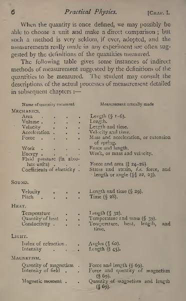
The following table gives some instances of indirect
methods of measurement suggested by the definitions of the
quantities to be measured. The student may consult the
descriptions of the actual processes of measurement detailed
in subsequent chapters :
Name of quantity measured
MECHANICS.AreaVolume .
VelocityAcceleration .
Force
Work .
Energy .
Fluid pressure (in abso-
lute units) .
Coefficients of elasticity
SOUND.
Velocity . .
Pitch .
HEAT.
Temperature .
Quantity of heat
Conductivity .
LIGHT.
Index of refraction .
Intensity
MAGNETISM.
Quantity of magnetismIntensity of field .
Magnetic moment .
Measurement actually made
Length ( 1-6).
Length.Length and time.
Velocity and time.
Mass and acceleration, or extension
of spring.Force and length.
Work, or mass and velocity.
Force and area( 24-26).
Stress and strain, i.e. force, and
length or angle ( 22, 23).
Length and time( 29).
Time ( 28).
Length ( 32).
Temperature and mass( 39).
Temperature, heat, length, andtime.
Angles ( 62).
Length ( 45).
Force and length ( 69).Force and quantity of magnetism
( 69).
Quantity of magnetism and length( 69).
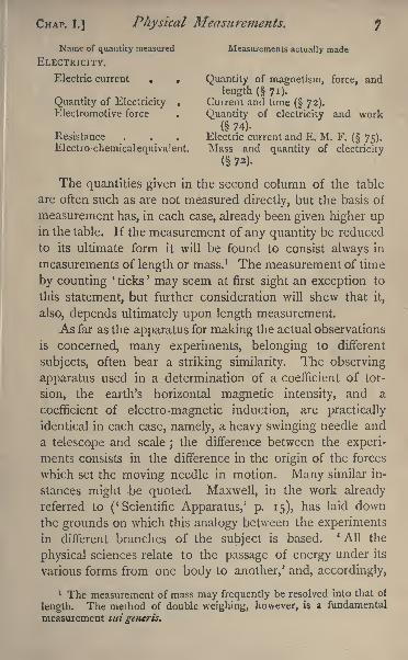
CHAP. I.] Physical Measurements. J
Name of quantity measured Measurements actually made
ELECTRICITY.
Electric current . . Quantity of magnetism, force, and
length (71)-Quantity of Electricity . Current and time
( 72).Electromotive force . Quantity of electricity and work
( 74).Resistance . . . Electric current and E. M. F. ( 75).Electro-chemical equivalent. Mass and quantity of electricity
( 72).
The quantities given in the second column of the table
are often such as are not measured directly, but the basis of
measurement has, in each case, already been given higher upin the table. If the measurement of any quantity be reduced
to its ultimate form it will be found to consist always in
measurements of length or mass. 1 The measurement of time
by counting'
ticks'
may seem at first sight an exception to
this statement, but further consideration will shew that it,
also, depends ultimately upon length measurement.
As far as the apparatus for making the actual observations
is concerned, many experiments, belonging to different
subjects, often bear a striking similarity. The observing
apparatus used in a determination of a coefficient of tor-
sion, the earth's horizontal magnetic intensity, and a
coefficient of electro-magnetic induction, are practically
identical in each case, namely, a heavy swinging needle and
a telescope and scale ;the difference between the experi-
ments consists in the difference in the origin of the forces
which set the moving needle in motion. Many similar in-
stances might -be quoted. Maxwell, in the work already
referred to ('Scientific Apparatus,' p. 15), has laid downthe grounds on which this analogy between the experimentsin different branches of the subject is based. * All the
physical sciences relate to the passage of energy under its
various forms from one body to another,' and, accordingly,
1 The measurement of mass may frequently be resolved into that of
length. The method of double weighing, however, is a fundamental
measurement sui generis.
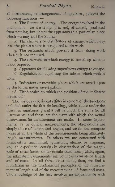
8 Practical Physics. [CHAP. I.
all instruments, or arrangements of apparatus, possess the
following functions :
'i. The Source of energy. The energy involved in the
phenomenon we are studying is not, of course, producedfrom nothing, but enters the apparatus at a particular placewhich we may call the Source.
'2. The channels or distributors of energy, which carry
it to the places where it is required to do work.
'3. The restraints which prevent it from doing work
when it is not required.
'4. The reservoirs in which energy is stored up when it
is not required.1
5. Apparatus for allowing superfluous energy to escape.'6. Regulators for equalising the rate at which work is
done.*
7. Indicators or movable pieces which are acted upon
by the forces under investigation.'8. Fixed scales on which the position of the indicator
is read off.'
The various experiments differ in respect of the functions
included under the first six headings, while those under the
headings numbered 7 and 8 will be much the same for all
instruments, and these are the parts with which the actual
observations for measurement are made. In some experi-
ments, as in optical measurements, the observations are
simply those of length and angles, and we do not compareforces at all, the whole of the measurements being ultimately
length measurements. In others we are concerned with
forces either mechanical, hydrostatic, electric or magnetic,
and an experiment consists in observations of the magni-tude of these forces under certain conditions
; while, again,
the ultimate measurements will be measurements of length
and of mass. In all these experiments, then, we find a
foundation in the fundamental principles of the measure-
ment of length and of the measurements of force and mass.
The knowledge of the first involves an acquaintance with
CHAP. I.] Physical Measurements. 9
some of the elementary properties of space, and to under-
stand the latter we must have some acquaintance with the
properties of matter, the medium by which we are able to
realise the existence of force and energy, and with the pro-
perties of motion, since all energy is more or less connected
with the motion of matter. We cannot, then, do better
than urge those who intend making physical experiments to
begin by obtaining a sound knowledge of those principles
of dynamics, which are included in an elementary account
of the science of matter and motion. The opportunity has
been laid before them by one to whom, indeed, manyother debts of gratitude are owed by the authors of this
work who was well known as being foremost in scientific
book-writing, as well as a great master of the subject. For
us it will be sufficient to refer to Maxwell's work on ' Mattel
and Motion '
as the model of what an introduction to the
study of physics should be.
CHAPTER II.
UNITS OF MEASUREMENT.
Method of Expressing a Physical Quantity.
IN considering how to express the result of a physical experi-
ment undertaken with a view to measurement, two cases
essentially different in character present themselves. In the
first the result which we wish to express is a concrete physical
quantity^ and in the second it is merely the ratio of two
physical quantities of the same kind, and is accordingly a
number. It will be easier to fix our ideas on this point if
we consider a particular example of each of these cases,
instead of discussing the question in general terms. Con-
sider, therefore, the difference in the expression of the result
of two experiments, one to measure a quantity of heat and
the second to measure a specific heat the measurements
IO Practical Physics. [CHAP. II.
of a mass and a specific gravity might be contrasted in a
perfectly similar manner in the former the numerical value
will be different for every different method employed to
express quantities of heat;while in the latter the result, being
a pure number, will be the same whatever plan of measuring
quantities of heat may have been adopted in the course of
the experiment, provided only that we have adhered through-out to the same plan, when once adopted. In the latter case,
therefore, the number obtained is a complete expression
of the result, while in the former the numerical value alone
conveys no definite information. We can form no estimate
of the magnitude of the quantity unless we know also the
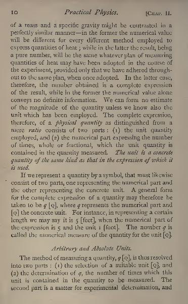
unit which has been employed. The complete expression,
therefore, of a physical quantity as distinguished from a
mere ratio consists of two parts : (i) the unit quantity
employed, and (2) the numerical part expressing the number
of times, whole or fractional, which the unit quantity is
contained in the quantity measured. The unit is a concrete
quantity of the same kind as that in the expression of which it
is used.
If we represent a quantity by a symbol, that must likewise
consist of two parts, one representing the numerical part and
the other representing the concrete unit. A general form
for the complete expression of a quantity may therefore be
taken to be q [Q], where q represents the numerical part and
[Q] the concrete unit. For instance, in representing a certain
length we may say it is 5 [feet], when the numerical part of
the expression is 5 and the unit i [foot]. The number q is
called the numerical measure of the quantity for the unit [Q].
Arbitrary and Absolute Units.
The method of measuring a quantity, q [Q],is thus resolved
into two parts : (i) the selection of a suitable unit [Q], and
(2) the determination of q, the number of times which this
unit is contained in the quantity to be measured. The
second part is a matter for experimental determination, and
CHAP. II.] Units of Measurement. 1 1
has been considered in the preceding chapter. We proceedto consider the first part more closely.
The selection of [Q] is, and must be, entirely arbitrary
that is, at the discretion of the particular observer who is
making the measurement. It is, however, generally wished
by an observer that his numerical results should be under-
stood and capable of verification by others who have not the
advantage of using his apparatus, and to secure this he must
be able so to define the unit he selects that it can be .repro-
duced in other places and at other times, or compared with
the units used by other observers. This tends to the general
adoption on the part of scientific men of common standards
of length, mass, and time, although agreement on this point
is not quite so general as could be wished. There are,
however, two well-recognised standards of length1
: viz. (i)
the British standard yard, which is the length at 62 F.
between two marks on the gold plugs of a bronze bar in
the Standards Office ;and (2) the standard metre as kept
in the French Archives, which is equivalent to 39*37079British inches. Any observer in measuring a length adoptsthe one or the other as he pleases. All graduated instru-
ments for measuring lengths have been compared either
directly or indirectly with one of these standards. If great
accuracy in length measurement is required a direct com-
parison must be obtained between the scale used and the
standard. This can be done by sending the instrument to be
used to the Standards Office of the Board of Trade.
There are likewise two well-recognised standards of
mass,
viz. (i) the British standard pound, a certain mass
of platinum kept in the Standards Office ;and (2) the
kilogramme des Archives, a mass of platinum kept in the
French Archives, originally selected as the mass of one thou-
sandth part of a cubic metre of pure water at 4 C. One
1 See Maxwell's Heat, chap. iv. The British Standards are nowkept at the Standards Office at the Board of Trade, Westminster, in
accordance with the *
Weights and Measures Act,' 1878.
12 Practical Physics. [CHAP. II.
or other of these standards, or a simple fraction or multipleof one of them, is generally selected as a unit in which to
measure masses by any observer making mass measure-
ments. The kilogramme and the pound were carefully com-
pared by the late Professor W. H. Miller;one pound is
equivalent to '453593 kilogramme.With respect to the unit of time there is no such
divergence, as the second is generally adopted as the unit
of time for scientific measurement. The second is-g-^V^i.
of the mean solar day, and is therefore easily reproducible-as long as the mean solar day remains of its present
length.
These units of length, mass, and time are perfectly arbi-
trary. We might in the same way, in order to measure anyother physical quantity whatever, select arbitrarily a unit
quantity of the same kind, and make use of it just as weselect the standard pound as a unit of mass and use it. Thusto measure a force we might select a unit of force, say the
force of gravity upon a particular body at a particular place,
and express forces in terms of it. This is the gravitation
method of measuring forces which is often adopted in
practice. It is not quite so arbitrary as it might have been,
for the body generally selected as being the body upon
which, at Lat. 45, gravity exerts the unit force is either the
standard pound or the standard gramme, whereas some other
body quite unrelated to the mass standards might have been
chosen. In this respect the gallon, as a unit of measurement
of volume, is a better example of arbitrariness. It contains
ten pounds of water at a certain temperature^
We may mention here, as additional examples of arbitrary
units, the degree as a unit of angular measurement, the
thermometric degree as the unit of measurement of tem-
perature, the calorie as a unit of quantity of heat, the standard
atmosphere, or atmo, as a unit of measurement of fluid
pressure, Snow Harris's unit jar for quantities of electricity,
and the B.A. unit of electrical resistance.
CHAP. II.] Units of Measurement. 13
Absolute Units.
The difficulty, however, of obtaining an arbitrary standard
which is sufficiently permanent to be reproducible makes this
arbitrary method not always applicable. A fair example of
this is in the case of measurement of electro-motive force,1
for which no generally accepted arbitrary standard has yet
been found, although ic has been sought for very diligently.
There are also other reasons which tend to make physicists
select the units for a large number of quantities with a view
to simplifying many of the numerical calculations in which
the quantities occur, and thus the arbitrary choice of a unit
for a particular quantity is directed by a principle of selection
which makes it depend upon the units already selected for
the measurement of other quantities. We thus get systems
of units, such that when a certain number of fundamental
units are selected, the choice of the rest follows from fixed
principles. Such a system is called an ' absolute'
system of
units, and the units themselves are often called 'absolute,'
although the term does not strictly apply to the individual
units. We have still to explain the principles upon which
absolute systems are founded
Nearly all the quantitative physical laws express relations
between the numerical measures of quantities, and the
general form of relation is that the numerical measure of
some quantity, Q, is proportional (either directly or inversely)
to certain powers of the numerical measures of the quan-tities x, Y, z . . . If q^ x, y, z, . . . be the numerical
measures of these quantities, then we may generalise the
physical law, and express it algebraically thus : q is propor-
tional to xa, y*
3
,zr
,. .
.,or by the variation equation
q oc xa. ft .
y. . . .
where a, /3, y may be either positive or negative, whole or frac-
tional. The following instances will make our meaning clear :
1 Since this was wittcn, Lord Ka) leigh has shewn that theE.M.F.of a Latimer-Ouk's cell is very nearly constant, and equal to 1-435volt at 15 G
14 Practical Physics. [CHAP. II.
(i.) The volumes of bodies of similar shape are propor-
tional to the third power of their linear dimensions, or
(2.) The rate of change of momentum is proportional to
the impressed force, and takes place in the direction in which
the force is impressed (Second Law of Motion), or
m a.
(3.) The pressure at any point of a heavy fluid is propor-
tional to the depth of the point, the density of the fluid, and
the intensity of gravity, or
(4.) When work produces heat, the quantity of heat
produced is directly proportional to the quantity of work
expended (First Law of Thermo-dynamics), or
(5.) The force acting upon a magnetic pole at the centre
of a circular arc of wire in which a current is flowing, is
directly proportional to the strength of the pole, the length
of the wire, and the strength of the current, and inversely
proportional to the square of the radius of the circle, or
and so on for all the experimental physical laws.
We may thus take the relation between the numerical
measures
q oc xa
y* zy . . .
to be the general form of the expression ot an experimental
law relating to physical quantities. This may be written in
the form
q= kxay
ls zf ...... (i)
when k is a 'constant.'
This equation, as we have already stated, expresses a
CHAP. Il.jUnits of Measurement. 15
relation between the numerical measures of the quantities
involved, and hence if one of the units of measurement is
changed, the numerical measure of the same actual quan-
tity will be changed in the inverse ratio, and the value of k
will be thereby changed.We may always determine the numerical value of k if
we can substitute actual numbers for q, x, y, z, ... in
the equation (i).
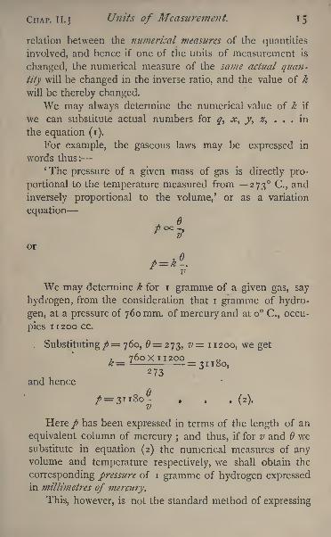
For example, the gaseous laws may be expressed in
words thus:* The pressure of a given mass of gas is directly pro-
portional to the temperature measured from 273 C., and
inversely proportional to the volume,' or as a variation
equation
or
We may determine k for i gramme of a given gas, say
hydrogen, from the consideration that i gramme of hydro-
gen, at a pressure of 760 mm. of mercury and at o C., occu-
pies IT 200 cc.
Substituting /= 760, 6= 273, v 11200, we get
and hence
/=3ii8o- . , . (2).
Here/ has been expressed in terms of the length of an
equivalent column of mercury ;and thus, if for v and we
substitute in equation (2) the numerical measures of anyvolume and temperature respectively, we shall obtain the
corresponding pressure of i gramme of hydrogen expressedin millimetres of mercury.
This, however, is not the standard method of expressing
1 6 Practical Physics. [CHAP. II.
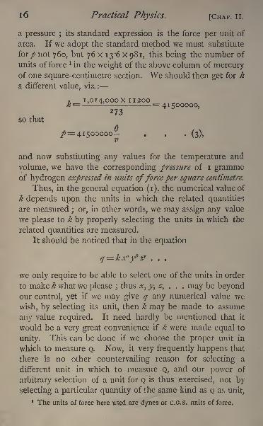
a pressure ; its standard expression is the force per unit of
area. If we adopt the standard method we must substitute
for/ not 760, but 76 x 13*6 x 981, this being the number of
units of force l in the weight of the above column of mercuryof one square-centimetre section. We should then get for k
a different value, viz. :
, I,OI4,OOOX II200K= - --- =41500000,
so thatA
p= 41500000- . . . (3),
and now substituting any values for the temperature and
volume, we have the corresponding pressure of i grammeof hydrogen expressed in units offorce per square centimetre.
Thus, in the general equation (i), the numerical value of
k depends upon the units in which the related quantities
are measured ; or, in other words, we may assign any value
we please to k by properly selecting the units in which the
related quantities are measured.
It should be noticed that in the equation
we only require to be able to select one of the units in order
to make k what we please ;thus x, y, z, . . . may be beyond
our control, yet if we may give q any numerical value we
wish, by selecting its unit, then k may be made to assume
any value required. It need hardly be mentioned that it
would be a very great convenience if k were made equal to
unity. This can be done if we choose the proper unit in
which to measure Q. Now, it very frequently happens that
there is no other countervailing reason for selecting a
different unit in which to measure Q, and our power of
arbitrary selection of a unit for Q is thus exercised, not by
selecting a particular quantity of the same kind as Q as unit,
1 The units offeree here used are dynes or C.G.s. units offeree.
CHAP. II.] Units of Measurement. 17
and holding to it however other quantities may be mea-
sured, but by agreeing that the choice of a unit for Qshall be determined by the previous selections of units for
x, y, z, . . . together with the consideration that the quancityk shall be equal to unity.
Fundamental Units and Derived Units.
It is found that this principle, when fully carried out,
leaves us free to choose arbitrarily three units, which are
therefore called fundamental units, and that most of the
other units employed in physical measurement can be defined
with reference to the fundamental units by the consider-
ation that the factor k in the equations connecting them
shall be equal to unity. Units obtained in this way are
called derived units, and all the derived units belong to an
absolute system based on the three fundamental units.
Absolute Systems of Units.
Any three units (of which no one is derivable from the
other two) may be selected as fundamental units. In those
systems, however, at present in use, the units of length,
mass, and time have been set aside as arbitrary fundamental
units, and the various systems of absolute units differ onlyin regard to the particular units selected for the measure-
ment of length, mass, and time. In the absolute system
adopted by the British Association, the fundamental units
selected are the centimetre, the gramme, and the second re-
spectively, and the system is, for this reason, known as the
C.G.S. system.
For magnetic surveying the British Government uses an
absolute system based on. the foot, grain, and second;and
scientific men on the Continent frequently use a systembased on the millimetre, milligramme, and second, as fun-
damental units. An attempt was also made, with partial
success, to introduce into England a system of absolute
units, based upon the foot, pound, and second as funda-
mental units.
c
18 Practical Physics. [ClIAP. II.
Hie
3 -bn <u n.S 3-t5l3 s
? c - "'
w S c ijw rt rt o,
^2 tij gJfl
H U
s
CHAP. II.] Units of Measurement.
.
20 Practical Physics. [CHAP. II.
c
CHAP. II.] Units of Measurement. 21
The C.G.S. System.
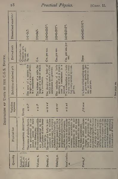
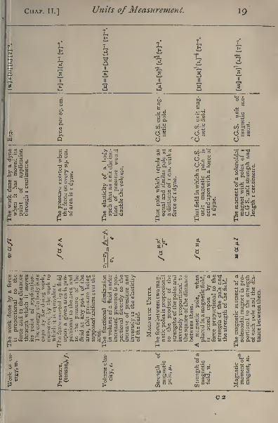
The table, p. 18, shows the method of derivation of
such absolute units on the C.G.S. system as we shall have
occasion to make use of in this book. The first column
contains the denominations of the quantities measured;
the second contains the verbal expression of the physical
law on which the derivation is based, while the third gives
the expression of the law as a variation equation jthe fourth
and fifth columns give the definition of the C.G.S. unit
obtained and the name assigned to it respectively, while the
last gives the dimensional equation. This will be explained
later (p. 24).
The equations given in the third column are reduced to
ordinary equalities by the adoption of the unit defined in
the next column, or of another unit belonging to an absolute
system based on the same principles.
Some physical laws express relations between quantities
whose units have already been provided for on the absolute
system, and hence we cannot reduce the variation equations
to ordinary equalities. This is the case with the formula for
the gaseous laws already mentioned (p. 15).
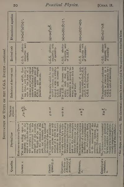
A complete system of units has thus been formed on
the C.G.S. absolute system, many of which are now in
practical use. Some of the electrical units are, however,
proved to be not of a suitable magnitude for the electrical
measurements most frequently occurring. For this reason
practical units have been adopted which are not identical
with the C.G.S. units given in the table (p. 20), but are
immediately derived from them by multiplication by some
power of 10. The names of the units in use, and the
factors of derivation from the corresponding C.G.S. units
are given in the following table :
22 Practical Physics. [CHAP. II.
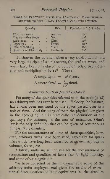
TABLE OF PRACTICAL UNITS FOR ELECTRICAL MEASUREMENTRELATED TO THE C.G.S. ELECTRO-MAGNETIC SYSTEM.
Quantity
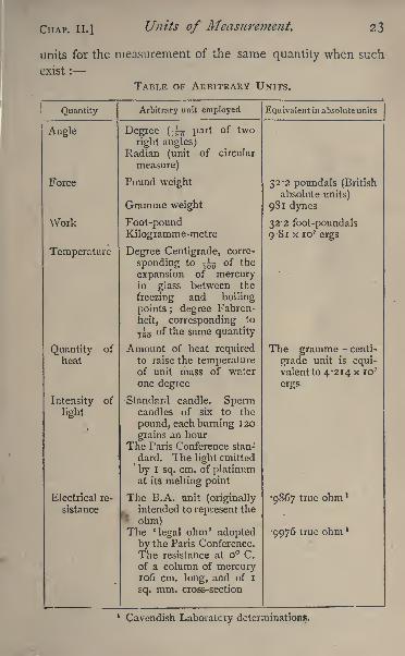
CHAP. II.]Units of Measurement. 23
units for the measurement of the same quantity when such
exist :
TABLE OF ARBITRARY UNITS.
Quantity
24 Practical Physics. [CHAP. II.
Changesfrom one Absolute System of Units to another.
Dimensional equations.
We have already pointed out that there are more than
one absolute system of units in use by physicists. They are
deduced in accordance with the same principles, but are
based on different values assigned to the fundamental units.
It becomes, therefore, of importance to determine the
factor by which a quantity measured in terms of a unit be-
longing to one system must be multiplied, in order to express
it in terms of the unit belonging to another system. Since
the systems are absolute systems, certain variation equationsbecome actual equalities ;
and since the two systems adoptthe same principles, the corresponding equations will have
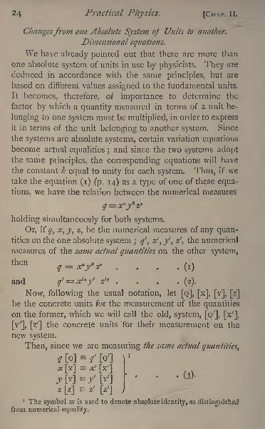
the constant k equal to unity for each system. Thus, if wetake the equation (i) (p, 14) as a type of one of these equa-
tions, we have the relation between the numerical measures
holding simultaneously for both systems.
Or, if q, x, y, z, be the numerical measures of any quan-tities on the one absolute system ; q' , x', y, z
f
,the numerical
measures of the same actual quantities on the other system,
thenq = x fz, ..,.(,)
and ?'= *'/ *'" (2)-
Now, following the usual notation, let [Q], [x], [Y], [z]
be the concrete units for the measurement of the quantities
on the former, which we will call the old, system, [Q'], [x'],
[Y'], [z']the concrete units Tor their measurement on the
new system.
Then, since we are measuring the same actual quantities,
y[v]=f [V]
W - *[z'J
1 The symbol = is used to denote ^bspiuie identity, as distinguishedfrom numerical equality.
CHAP. II.] Units of Measurement. 25
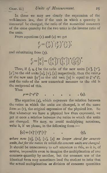
In these we may see clearly the expression of the
well-known law, that if the unit in which a quantity is
measured be changed, the ratio of the numerical measures
of the same quantity for the two units is the inverse ratio of
the units.
From equations (i) and (2) we get
and substituting from (3).
Thus, if, 17, be the ratio of the new units [x'], [Y
;
],
[z'] to the old units [x], [Y], [z] respectively, then the ratio p
of the new unit [Q'] to the old unit [Q] is equal to *vft?,
and the ratio of the new numerical measure to the old is
the reciprocal of this.
Thus
P= *Vfr . . . (4).
The equation (4), which expresses the relation between
the ratios in which the units are changed, is of the same
form as (i), the original expression of the physical law. So
that whenever we have a physical law thus expressed, we
get at once a relation between the ratios in which the units
are changed. We may, to avoid multiplying notations,
write it, if we please, in the following form :
[Q]=
[X]-[Y][Z]' (5),
where now [Q], [x], [Y], [z] no longer stand for concrete
units, butfor the ratios in which the concrete units are changed.
It should be unnecessary to call attention to this, as it is, of
course, impossible even to imagine the multiplication of one
concrete quantity by another, but the constant use of the
identical form may sometimes lead the student to infer that
the actual multiplication or division of concrete quantities
26 Practical Physics. [CHAP. II.
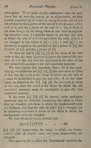
takes place. If we quite clearly understand that the sen-
tence has no meaning except as an abbreviation, we mayexpress equation (5) in words by saying that the unit of Q is
the product of the a power of the unit of x, the ft power of the
unit of Y, and the y power of the unit of z;but if there is
the least danger of our being taken at our word in express-
ing ourselves thus, it would be better to say that the ratio
in which the unit of Q is changed when the units of x, Y, z
are changed in the ratios of [x] : i [Y] : i and [z] : i re-1
spectively is equal to the product of the a power of [x], the
/? power of [Y], and the y power of[z].
We thus see that if [x], [Y], [z] be the ratios of the new
units to the old, then equation (5) gives the ratio of the new
unit of Q to the old, and the reciprocal is the ratio. of the
new numerical measure to the old numerical measure.
We may express this concisely, thus : If in the equa-
tion (5) we substitute for [x], [Y], [z] the new units in terms
of the old, the result is the factor by which the old unit of
Q must be multiplied to give the new unit ; if, on the other
hand, we substitute for [x], [Y], [z] the old units in terms
of the new, then the result is the factor by which the old
numerical measure must be multiplied to give the new
numerical measure.
If the units [x], [Y], [z] be derived units, analogous
equations may be obtained, connecting the ratios in which
they are changed with those in which the fundamental units
are changed, and thus the ratio in which [Q] is changed can
be ultimately expressed in terms of the ratios in which the
fundamental units are changed.
We thus obtain for every derived unit
[L], [M], [T] representing the ratios in which the funda-
mental units of length, mass, and time, respectively, are
changed.The equation (6) is called the dimensional equation for
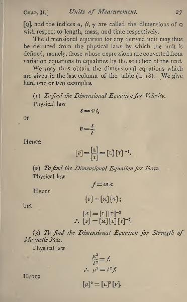
CHAP. IT.] Units of Measurement. 27
[Q], and the indices a, (3, y are called the dimensions of Qwith respect to length, mass, and time respectively.
The dimensional equation for any derived unit may thus
be deduced from the physical laws by which the unit is
denned, namely, those whose expressions are converted from
variation equations to equalities by the selection of the unit.
We may thus obtain the dimensional equations which
are given in the last column of the table (p. 18). We give
here one or two examples.
(i) To find the Dimensional Equation for Velocity.
Physical law
s-=vtt
or
Hence
(2) Tofind the Dimensional Equation for Force.
Physical law
f= m a.
Hecce
W-MWsbut
W-WW-*M = [M]M[T]-'.
(3) To find the Dimensional Equation for Strength of
Magnetic Pole.
Physical law
Hence
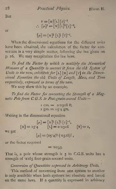
23 Practical Physics. [CHAP. II.
But
or
When the dimensional equations for the different units
have been obtained, the calculation of the factor for con-
version is a very simple matter, following the law given on
p. 26. We may recapitulate the law here.
To find the Factor by which to multiply the Numerical
Measure of a Quantity to convert it from the old System ofUnits to the new, substitutefor [L] [M] and [T] in the Dimen-
sional Equation the old Units of Length, Mass, and Time
respectively, expressed in terms of the new.
We may shew this by an example.
To find the Factor for converting the Strength of a Mag-netic Polefrom C.G.S. to Foot-gram-second Units
i cm. = 0-0328 ft.
i gm.= 15-4 grs.
Writing in the dimensional equation
M=[M]i[L]l[T]^[M]=i5'4 [L]
= 0-0328 [T]=
I,
we get
M = (15-4)* (-0328)!,
or the factor required= -0233.
That is, a pole whose strength is 5 in C.G.S. units has a
strength of '1165 foot-grain-second units.
Conversion of Quantities expressed in Arbitrary Units.
This method of converting from one system to another
is only available when both systems are absolute and based
on the same laws. If a quantity is expressed in arbitrary
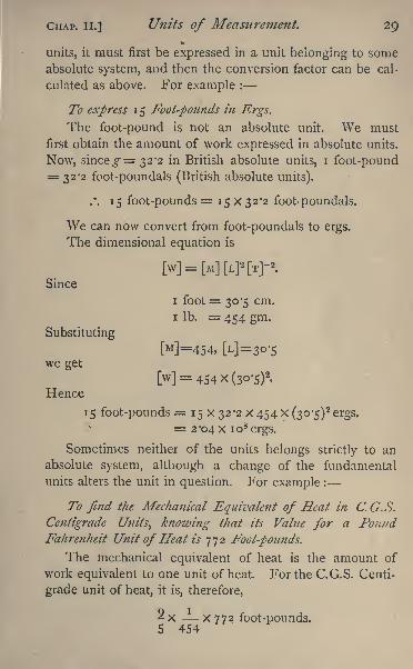
CHAP. II.] Units of Measurement. 29%
units, it must first be expressed in a unit belonging to some
absolute system, and then the conversion factor can be cal-
culated as above. For example :
To express 15 foot-pounds in Ergs.
The foot-pound is not an absolute unit. We must
first obtain the amount of work expressed in absolute units.
Now, sinceg= 32-2 in British absolute units, i foot-pound= 32-2 foot-poundals (British absolute units).
.*. 15 foot-pounds = 15 X32'2 foot-poundals.
We can now convert from foot-poundals to ergs.
The dimensional equation is
M-MWM-*.Since
i foot = 30-5 cm.
i Ib. = 454 gm.
Substituting
[M]=454, [L]= 3o-s
we get
[w]= 454 x (30-5)2.
Hence
15 foot-pounds = 15 x 32-2 x 454 x (30-5)2 ergs.
= 2'04X io8ergs.
Sometimes neither of the units belongs strictly to an
absolute system, although a change of the fundamental
units alters the unit in question. For example :
To find the Mechanical Equivalent of Heat in C. G. S.
Centigrade Units, knowing that its Value for a PoundFahrenheit Unit of Heat is 772 Foot-pounds.
The mechanical equivalent of heat is the amount of
work equivalent to one unit of heat. For the C.G.S. Centi-
grade unit of heat, it is, therefore,
2x - X772 foot-pounds.5 454
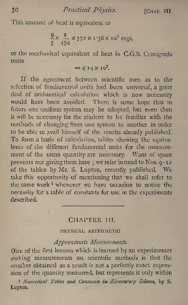
3 Practical Physics. [CHAP, III
This amount of heat is equivalent to
2x- X772 x i'36x io7ergs,
5 454
or the mechanical equivalent of heat in C.G.S. Centigradeunits
= 4*14 x io7.
If the agreement between scientific men as to the
selection of fundamental units had been universal, a greatdeal of arithmetical calculation which is now necessarywould have been avoided. There is some hope that in
future one uniform system may be adopted, but even then
it will be necessary for the student to be familiar with the
methods of changing from one system to another in order
to be able to avail himself of the results already published.
To form a basis of calculation, tables showing the equiva-lents of the different fundamental units for the measure-
ment of the same quantity are necessary. Want of space
prevents our giving them here;we refer instead toNos. 9-12
of the tables by Mr. S. Lupton, recently published. Wetake this opportunity of mentioning that we shall refer to
the same work * whenever we have occasion to notice the
necessity for a table of constants for use in the experimentsdescribed.
CHAPTER III.
PHYSICAL ARITHMETIC
Approximate Measurements.
ONE of the first lessons which is learned by an experimenter
making measurements on scientific methods is that the
number obtained as a result is not a perfectly exact expres-
sion of the quantity measured, but represents it only within
1 Numerical Tables and Constants in Elementary Science^ by S.
Lupton.
CHAP. III.] Physical Arithmetic. 31
certain limits of error. If the distance between two towns
be given as fifteen miles, we do not understand that the
distance has been measured and found to be exactly fifteen
miles, without any yards, feet, inches, or fractions of an
inch, but that the distance is nearer to fifteen miles than it
is to sixteen or fourteen. If we wished to state the distance
more accurately we should have to begin by defining two
points, one in each town marks, for instance, on the door-
steps of the respective parish churches between which the
distance had been taken, and we should also have to sped .y
the route taken, and so on. To determine the distance
with the greatest possible accuracy would be to go through
the laborious process of measuring a base line, a roughidea of which is given in 5. We might then, perhaps,
obtain the distance to the nearest inch and still be uncertain
whether there should not be a fraction of an inch more or
less, and if so, what fraction it should be. If the number
is expressed in the decimal notation, the increase in the
accuracy of measurement is shewn by filling up more
decimal places. Thus, if we set down the mechanical
equivalent of heat at 4*2 x io7ergs, it is not because the
figures in the decimal places beyond the 2 are all zero, but
because we do not know what their values really are, or it
may be, for the purpose for which we are using the value,
it is immaterial what they are. It is known, as a matter
of fact, that a more accurate value is 4*214 x io7,but at
present no one has been able to determine what figure
should be put in the decimal place after the 4.
Errors and Corrections.
The determination of an additional figure in a number
representing the magnitude of a physical quantity generally
involves a very great increase in the care and labour which
must be bestowed on the determination. To obtain some
idea of the reason for this, let us take, as an example, the
case of determining the mass of a body of about 100
32 Practical Physics. [CHAP. III.
grammes. By an ordinary commercial balance the mass of
a body can be easily and rapidly determined to i gramme,say 103 grammes. With a better arranged balance we mayshew that 103-25 is a more accurate representation of the
mass. We may then use a very sensitive chemical balance
which shews a difference of mass of o'i mgm., but which
requires a good deal of time and care in its use, and
get a value 103*2537 grammes .as the mass. But, if nowwe make another similar determination with another
balance, or even with the same balance, at a different time,
we may find the result is not the same, but, say, 103 2546
grammes. We have thus, by the sensitive balance, carried
the measurement two decimal places further, but have gotfrom two observations two different results, and have, there-
fore, to decide whether either of these represents the mass
of the body, and, if so, which. Experience has shewn that
some, at any rate, of the difference may be due to the
balance not being in adjustment, and another part to the
fact that the body is weighed in air and not in vacuo. Theobserved weighings may contain errors due to these causes.
The effects of these causes on the weighings can be cal-
culated when the ratio of the lengths of the arms and other
facts about the balance have been determined, and when
the state of the air as to pressure, temperature, and moisture
is known (see 13, 14).
We may thus, by a series of auxiliary observations,
determine a correction to the observed weighing correspond-
ing to each known possible error. When the observations
are thus corrected they will probably be very much closer.
Suppose them to be 103 2543 and 103 '2542.
Mean of Observations.
When all precautions have been taken, and all known
errors corrected, there may still be some difference between
different observations which can^j&nly arise from causes
beyond the knowledge and control of the observer. We
CHAP. III.] Physical Arithmetic. 33
must, therefore, distinguish between errors due to known
causes, which can be allowed for as corrections, or elimi-
nated by repeating the observations under different con-
ditions, and errors due to unknown causes, which are called
'accidental'
errors. Thus, in the instance quoted, we knowof no reason for taking 103-2543 as the mass of the body in
preference to 103 '2542. It is usual in such cases to take
the arithmetic mean of the two observations, i.e. the number
obtained by adding the two values together, and dividing by
2, as the nearest approximation to the true value.
Similarly if any number, n, of observations be taken,
each one of which has been corrected for constant errors,
and is, therefore, so far as the observer can tell, as worthyof confidence as any of the others, the arithmetic mean of
the values is taken as that most nearly representing the true
value of the quantity. Thus, if q\, q^ q$ qn be the
results of the n observations, the value of q is taken to be
It is fair to suppose that, if we take a sufficient numberof observations, some of them give results that are too
large, others again results that are too small;and thus, by
taking the mean of the observations as the true value, we
approach more nearly than we can be sure of doing by
adopting any single one of the observations.
We have already mentioned that allowance must be
made by means of a suitable correction for each constant
error, that is for each known error whose effect upon the
result may be calculated or eliminated by some suitable
arrangement. It is, of course, possible that the observer
may have overlooked some source of constant error whichwill affect the final result. This must be very carefully
guarded against, for taking the mean of a number of obser-
D
34 Practical Physics. [CHAP. III.
vations affords, in general, no assistance m the elimination
of an error of that kind.
The difference between the mean value and one of the
observations is generally known technically as the ' error'
of that observation. The theory of probabilities has been
applied to the discussion of errors of observations !
,and it
has been shewn that by taking the mean of n observations
instead of a single observation, the so-called 'probable
error'
is reduced in the ratio of i / >J~nI
On this account alone it would be advisable to take
several observations of each quantity measured in a physical
experiment. By doing so, moreover, we not only get a
result which is probably more accurate, but we find out to
what extent the observations differ from each other, and
thus obtain valuable information as to the degree of accuracyof which the method of observation is capable. Thus we
have, on p. 54, four observations of a length, viz.
3'333 in.
3'33 2
3*334
3 "334
Mean =: 3-3332
Taking the mean we are justified in assuming that the
true length is accurately represented by 3*333 to the third
decimal place, and we see that the different observations
differ only by two units at most in that place.
In performing the arithmetic for finding the mean of a
number of observations, it is only necessary to add those
columns in which differences occur the last column of
the example given above. Performing the addition on the
other columns would be simply multiplying by 4, by which
number we should have subsequently to divide.
An example will make this clear.
1 See Airy's tract on the Theory of Errors of Observations.
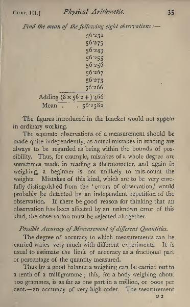
CHAP, in.] Physical Arithmetic. 35
Find the mean of thefollowing eight observations :
56-231
56-275
56-243
56-255
56-256
56-267
56-273
56-266
Adding (8 x 56-2 +) -466
Mean"! . 56-2582
The figures introduced in the bracket would not appearin ordinary working.
The separate observations of a measurement should be
made quite independently, as actual mistakes in reading are
always to be regarded as being within the bounds of pos-
sibility. Thus, for example, mistakes of a whole degree are
sometimes made in reading a thermometer, and again in
weighing, a beginner is not unlikely to mis-count the
weights. Mistakes of this kind, which are to be very care-
fully distinguished from the *
errors of observation,' would
probably be detected by an independent repetition of the
observation. If there be good reason for thinking that an
observation has been affected by an unknown error of this
kind, the observation must be rejected altogether.
Possible Accuracy ofMeasurement of different Quantities.
The degree of accuracy to which measurements can be
carried varies very much with different experiments. It is
usual to estimate the limit of accuracy as a fractional part
or percentage of the quantity measured.
Thus by a good balance a weighing can be carried out to
a tenth of a milligramme ; this, for a body weighing about
100 grammes, is as far as one part in a million, or -oooi percent. an accuracy of very high order. The measurement
D 2
36 Practical Physics. [CHAP. III.
of a large angle by the spectrometer ( 62) is likewise
very accurate;
thus with a vernier reading to 20", an
angle of 45 can be read to one part in four thousand, or
0*025 per cent. On the other hand, measurements of
temperature cannot, without great care, be carried to a
greater degree of accuracy than one part in a hundred, or
i per cent., and sometimes do not reach that. A length
measurement often reaches about one part in ten thousand.
For most of the experiments which are described in this
work an accuracy of one part in a thousand is ample, indeed
generally more than sufficient.
It is further to be remarked that, if several quantities
have to be observed for one experiment, some of them maybe capable of much more accurate determination than
others. It is, as a general rule, useless to carry the accuracy
of the former beyond the possible degree of accuracy of the
latter. Thus, in determining specific heats, we make some
weighings and measure some temperatures. It is useless to
determine the weights to a greater degree of accuracy than
one part in a thousand, as the accuracy of the result will
not reach that limit in consequence of the inaccuracy of the
temperature measurements. In some cases it is necessary
that one measurement should be carried out more accurately
than others in order that the errors in the result may be all
of the same order. The reason for this will be seen on p. 48.
Arithmetical Manipulation of Approximate Values.
In order to represent a quantity to the degree of accuracyof one part in a thousand, we require a number with four
digits at most, exclusive of the zeros which serve to mark the
position of the number in the decimal scale. ! It frequently
1 It is now usual, when a very large number has to be expressed, to
write down the digits with a decimal point after the first, and indicate
its position in the scale by the power of 10, by which it must be mul-
tiplied : thus, instead of 42140000 we write 4*214 * io7. A corre-
sponding notation is used for a very small decimal fraction : thus,
instead of -00000588 we write 5-88 x io~ 6.
CHAP, ill.] Physical Arithmetic. 37
happens that some arithmetical process, employed to deduce
the required result from the observations, gives a number
containing more than the four necessary digits. Thus, if
we take seven observations of a quantity, each to three
figures, and take the mean, we shall usually get any number
of digits we please when we divide by the 7. But we know
that the observations are only accurate to three figures;
hence, in the mean'obtained, all the figures after the fourth,
at any rate, have no meaning. They are introduced simply
by the arithmetical manipulation, and it is, therefore, better
to discard them. It is, indeed, not only useless to retain
them, but it may be misleading to do so, for it may give the
reader of the account of the experiment an impression that
the measurements have been carried to a greater degree of
accuracy than is really the case. Only those figures, there-
fore, which really represent results obtained by the measure-
ments should be included in the final number. In dis-
carding the superfluous digits we must increase the last
digit retained by unity, if the first digit discarded is 5
or greater than 5. Thus, if the result of a division gives
3 2 '3 1 6, we adopt as the value 32*32 instead of 32*31.
For it is evident that the four digits 32*32 more nearly re-
present the result of the division than the four 32*31.
Superfluous figures very frequently occur in the multi-
plication and division of approximate values of quantities.
These have also to be discarded from the result ;for if we
multiply two numbers, each of which is accurate only to
one part in a thousand, the result is evidently only accurate
to the same degree, and hence all figures after the fourth
must be discarded.
The arithmetical manipulation may be performed by
using logarithms, but it is sometimes practically shorter to
work out the arithmetic than to use logarithms ;and in
this case the arithmetical process may be much abbreviated
by discarding unnecessary figures in the course of the
work.
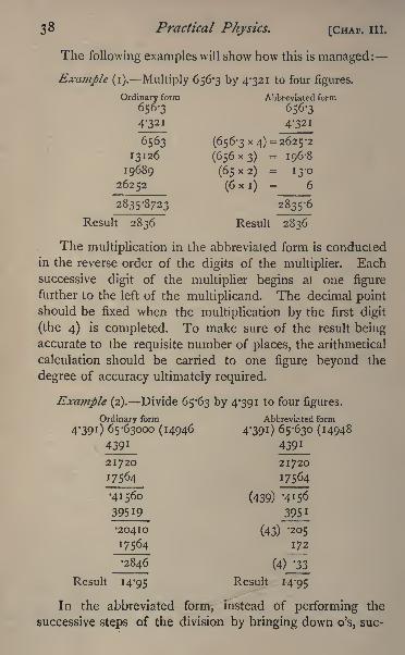
38 Practical Physics. [CHAP. III.
The following examples will show how this is managed:
Example (i). Multiply 656-3 by 4-321 to four figures.
Ordinary form Abbreviated form
656-3 656-3
4-32I 4-32I
6563 (656-3x4) =2625-2
I3I26 (656x3) = 196-8
19689 (65x2) = 13-0
26252 (6 x i)= 6
2835-8723 2835-6
Result 2836 Result 2836
The multiplication in the abbreviated form is conducted
in the reverse order of the digits of the multiplier. Each
successive digit of the multiplier begins at one figure
further to the left of the multiplicand. The decimal pointshould be fixed when the multiplication by the first digit
(the 4) is completed. To make sure of the result beingaccurate to the requisite number of places, the arithmetical
calculation should be carried to one figure beyond the
degree of accuracy ultimately required.
Example (2). Divide 65-63 by 4-391 to four figures,
Ordinary form Abbreviated form
4-391) 65-63000 (14946 4'390 65-630 (14948
4391 4391
21720
17564
(439) -4156
3951
20410 (43) -205
17564 172
2846 (4) '33
Result 14-95 Result 14-95
In the abbreviated form, instead of performing the
successive steps of the division by bringing down o's, sue-
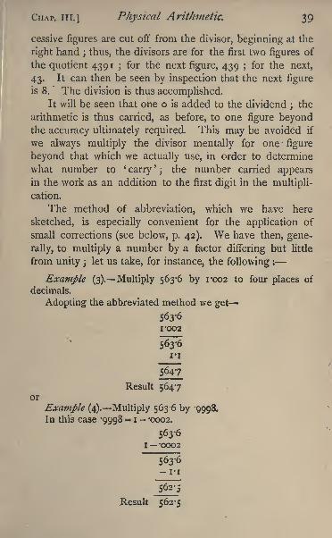
CHAP. III.] Physical Arithmetic. 39
cessive figures are cut off from the divisor, beginning at the
right hand ; thus, the divisors are for the first two figures of
the quotient 4391 ;for the next figure, 439 for the next,
43. It can then be seen by inspection that the next figure
is 8. The division is thus accomplished.It will be seen that one o is added to the dividend ;
the
arithmetic is thus carried, as before, to one figure beyondthe accuracy ultimately required. This may be avoided if
we always multiply the divisor mentally for one figure
beyond that which we actually use, in order to determine
what number to'
carry'
the number carried appearsin the work as an addition to the first digit in the multipli-
cation.
The method of abbreviation, which we have here
sketched, is especially convenient for the application of
small corrections (see below, p. 42). We have then, gene-
rally, to multiply a number by a factor differing but little
from unity ; let us take, for instance, the following :
Example (3). Multiply 563*6 by 1*002 to four places of
decimals.
Adopting the abbreviated method we get
563*6
1*002
I'l
5647
Result 5647or
Example (4). Multiply 563-6 by '9998.
In this case '9998 = I - -0002.
I *OOO2
1*1
Result 562*5
4O Practical Physics. [CHAP. III.
It will be shewn later (p. 44) that dividing by '9998 is
the same, as far as the fourth place of decimals is concerned,
as multiplying by 1-002, and vice versa-, this suggests the
possibility of considerable abbreviation of arithmetical cal-
culation in this and similar cases.
Facilitation of Arithmetical Calculation by means of
Tables. Interpolation.
The arithmetical operations of multiplication, division,
the determination of any power of a number, and the ex-
traction of roots, may be performed, to the required degreeof approximation, by the use of tables of logarithms. Themethod of using these for the purposes mentioned is so
well known that it is not necessary to enter into details here.
A table of logarithms to four places of decimals is given in
Lupton's book, and is sufficient for most of the calculations
that we require. If greater accuracy is necessary, Cham-bers's tables may be used. Instead of tables of logarithms,a *
slide-rule'
is sometimes employed. The most effective is
probably 'Fuller's spiral slide rule,' which is made and
sold by Stanley of Holborn. By this two numbers of four
figures can be multiplied or divided.
Besides tables of logarithms, tables of squares, cubes,
square roots, cube roots, and reciprocals may be used.
Short tables will be found in Lupton's book (pp. 1-4); for
more accurate work Barlow's tables should be used.
Besides these the student will require tables of the trigono-
metrical functions, which will also be found among Lupton'stables.
An arithmetical calculation can frequently be simplified
on account of some special peculiarity. Thus, dividing by
5 is equivalent to multiplying by 2, and moving the decimal
point one place to the left. Again, 7r2 = 9-87 = 10 -13,
and many other instances might be given ;but the student
can only make use of such advantages by a familiar acquaint-ance with cases in which they prove of service.
CHAP. III.] Physical Arithmetic. 41
In some cases the variations of physical quantities are
also tabulated, and the necessity of performing the arith-
metic is thereby saved. Thus, No. 31 of Lupton's tables
gives the logarithms of (i + 'oc^y/) for successive degreesof temperature, and saves calculation when the volume or
pressure of a mass of gas at a given temperature is required.
A table of the variation of the specific resistance of copperwith variation of temperature, is given on p. 47 of the same
work.
It should be noticed that all tables proceed by certain
definite intervals of the varying element;
for instance, for
successive degrees of temperature, or successive units in the
last digit in the case of logarithms ;and it may happen that
the observed value of the element lies between the values
given in the table. In such cases the required value can
generally be obtained by a process known as 'interpolation.'
If the successive intervals, for which the table is formed, are
small enough, the tabulated quantity may be assumed to
vary uniforntly between two successive steps of the varying
element, and the increase in the tabulated quantity may be
calculated as being proportional to the increase of the vary-
ing element. We have not space here to go more into
detail on this question, and must content ourselves with say-
ing that the process is strictly analogous to the use of '
pro-
portional parts' in logarithms. We may refer to 12, 19,
77 for examples of the application of a somewhat analogousmethod of physical interpolation.
Algebraical Approximation. Approximate Formula,
Introduction of small Corrections.
If we only require to use a formula to give a result
accurate within certain limits, it is, in many cases, possibleto save a large amount of arithmetical labour by altering the
form of the formula to be employed. This is most frequentlythe case when any small correction to the value of one of
the observed elements has to be introduced, as in the case,
42 Practical Physics. [CHAP. III.
for instance, of an observed barometric height which has to
be corrected for temperature. We substitute for the strictly
accurate formula an approximate one, which renders the
calculation easier, but in the end gives the same result to
the required degree of accuracy.We have already said that an accuracy of one part in a
thousand is, as a rule, ample for our purpose ;and we may,
therefore, for the sake of definiteness, consider the simplifi-
cation of algebraical formulae with the specification of one
part in a thousand, or o'i per cent., as the limit of accuracydesired. Whatever we have to say may be easily adaptedfor a higher degree of accuracy, if such be found to be
necessary.
It is shewn in works on algebra that
(i + x)n= i + n x+
n -^^'x2+ terms involving higher2
powers of x........ (i).
This is known as the * binomial theorem/ and is true
for all values of n positive or negative, integral or frac-
tional. Some special cases will probably be familiar to
every student, as :
If we change the sign of x we get the general formula
in the form
We may include both in one form, thus :
where the sign means that either the + or the is
to be taken throughout.
CHAP. III.] Physical Arithmetic. 43
Now, if x be a small fraction, say, i/iooo or o'ooi, xz
is evidently a much smaller fraction, namely, 1/1000,000, or
o-oooooi, and .v3
is still smaller. Thus, unless n is very
large indeed, the term
will be too small to be taken account of, and the terms which
follow will be of still less importance. We shall probably
not meet with formulae in which n is greater than 3. Let
us then determine the value of x so that
> 13*
may be equal to!
ooi, that is to say, may just make itself
felt in the calculations that we are now discussing.
Putting n = 3 we get
3A;2 = 'ooi
x ^ -00033= '02 roughly.
So that we shall be well within the truth if we say that
(when n = 3), if x be not greater than o'oi, the third term
of equation (i) is less than *ooi, and the fourth term less
than -oooo i. Neither of these, nor anyone beyond them,
will, therefore, affect the result, as far as an accuracy of one
part in a thousand is concerned;and we may, therefore,
say that, if x is not greater than o'oi,
To use this approximate formula when x= o'oi would be
inadmissible, as it produces a considerable effect upon the
next decimal place ; and, if in the same formula, we make
other approximations of a similar nature, the accumulation
of approximation may impair the accuracy of the result.
In any special case, therefore, it is well to consider
44 Practical Physics. [CHAP. III.
whether x is small enough to allow of the use of the approxi-
mate formula by roughly calculating the value of the third
term;
it is nearly always so if it is less than -005. This in-
cludes the important case in which x is the coefficient of
expansion of a gas for which x = '00366.
If n be smaller than 3, what we have said is true within
still closer limits;and as n is usually smaller than 3, we
may say generally that, for our purposes,
(i+.v)"= i !#,and
(ix)ni nx,
provided x be less than 0*005.
Some special cases of the application of this method of
approximation are here given, as they are of frequent occur-
rence :
(l#)2= I2X(ix)3 = i 3*
</Ix = (i *)t = i ?
ix
The formulae for +x and x are here included in one
expression ; the upper or lower sign must be taken through-out the formula.
We thus see that whenever a factor of the form (i^)'occurs in a formula where x is a small fraction, we ma)replace it by the simpler but approximate factor i_nx\and we have already shown how the multiplication by such
a factor may be very simply performed (p. 39). Cases o>
the application of this method occur in 13, 24 etc.
Another instance of the change of formula foi fhe pur
CHAP. III.] Physical Arithmetic. 45
poses of arithmetical simplicity is made use of in 13.
In that case we obtain a result as the geometric mean of
two nearly equal quantities. It is an easy matter to prove
algebraically, although we have not space to give the proof
here, that the geometric mean of two quantities which differ
only by one part in a thousand differs from the arithmetic
mean of the two quantities by less than the millionth of
either. It is a much easier arithmetical operation to find
the arithmetic mean than the geometric, so that we substi-
tute in the formula (x+x')/2 for *J x x'.
The calculation of the effect upon the trigonometrical
ratios of an angle, due to a small fractional increase in the
angle, may be included in this section. We know that
sin (6+ d) = sin 6 cos d 4- cos 6 sin d.
Now, reference to a table of sines and cosines will shew
that cos d differs from unity by less than one part in a
thousand if d'be less than 2 33', and, if expressed in circular
measure, the same value of d differs from sin d by one part
in three thousand; so we may say that, provided dis less
than 2|, cos d is equal to unity, and sin d is equal to d
expressed in circular measure.
The formula is, therefore, for our purposes, equivalent to
sin + d = sin Q+ d cos 6.
We may reason about the other trigonometrical ratios in
a similar manner, and we thus get the following approximateformulae :
sin (0d) = sin 6Jcos 0.
cos (Qd) = cos <9zp</sin (9.
tan (0d) = tan <9</sec 20.
The upper or lower sign is to be t*aken throughout the
formula.
If d be expressed in degrees, then, since the circular
46 Practical Physics. [CHAP. III.
measure of i is 7r/i8o, that of d is */7r/i8o, and the
formulae become
sin (6d) = sin^180
&c.
It has been already stated that approximate formulae are
frequently available when it is required to introduce correc-
tions for variations of temperature, and other elements which
may be taken from tables of constants. There is besides
another use for them which should not be overlooked,
namely, to calculate the effect upon the result of an error of
given magnitude in one of the observed elements. This is
practically the same as calculating the effect of a hypothe-tical correction to one of the observed elements. In cases
where the formula of reduction is simply the product or
quotient of a number of factors each of which is observed
directly, a fractional error of any magnitude in one of the
factors produces in the result an error of the same frac-
tional magnitude, but in other cases the effect is not so
simply calculated. If we take one example it will serve to
illustrate our meaning, and the general method of employ-
ing the approximate formulae we have given in this chapter.
In 75 electric currents are measured by the tangent
galvanometer. Suppose that in reading the galvanometerwe cannot be sure of the position of the needle to a
greater accuracy than a quarter of a degree. Let us, there-
fore, c onsider the following question :
* To find the effect
upon the value of a current, as deduced from observations
with the tangent galvanometer, of an error of a quarter of a
degree in the reading?
The formula of reduction is
c = k tan 0.
Suppose anerror^S has been made in the reading of 0,
so that the observed value is
(p. 45)
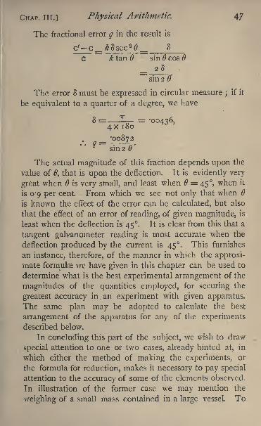
CHAP, in.] Physical Arithmetic. 47
The fractional error q in the result is
c'--c/&8sec 2(9 8_ _
c k tan sin cos
= 28
sin 2 0'
The error 8 must be expressed in circular measure ;if it
be equivalent to a quarter of a degree, we have
_ -0087^2' *
sufafl."
The actual magnitude of this fraction depends upon the
value of 0, that is upon the deflection. It is evidently very
great when is very small, and least when = 45, when it
is 0-9 per cent. From which we see not only that when
is known the effect of the error can be calculated, but also
that the effect of an error of reading, of given magnitude, is
least when the deflection is 45. It is clear from this that a
tangent galvanometer reading is most accurate when the
deflection produced by the current is 45. This furnishes
an instance, therefore, of the manner in which the approxi-
mate formulae we have given in this chapter can be used to
determine what is the best experimental arrangement of the
magnitudes of the quantities employed, for securing the
greatest accuracy in.an experiment with given apparatus.
The same plan may be adopted to calculate the best
arrangement of the apparatus for any of the experimentsdescribed below.
In concluding this part of the subject, we wish to draw
special attention to one or two cases, already hinted at, in
which either the method of making the experiments, or
the formula for reduction, makes it necessary to pay special
attention to the accuracy of some of the elements observed.
In illustration of the former case we may mention the
weighing of a small mass contained in a large vessel. To
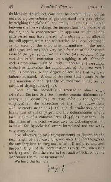
43 Practical Physics. [CHAP. III.
fix ideas on the subject, consider the determination of the
mass of a given volume of gas contained in a glass globe,
by weighing the globe full and empty. During the interval
between the two weighings the temperature and pressure of
the air, and in consequence the apparent weight of the
glass vessel, may have altered. This change, unless allowed
for, will appear, when the subtraction has been performed,as an error of the same actual magnitude in the mass
of the gas, and may be a very large fraction of the observed
mass of the gas, so that we must here take account of the
variation in the correction for weighing in air, althoughsuch a precaution might be quite unnecessary if we simplywished to determine the actual mass of the glass vessel
and its contents to the degree of accuracy that we have
hitherto assumed. A case of the same kind occurs in the
determination of the quantity of moisture in the air bymeans of drying tubes
( 42).
Cases of the second kind referred to above often
arise from the fact that the formulas contain differences of
nearly equal quantities ;we may refer to the formulae
employed in the correction of the first observations
with Atwood's machine( 21), the determination of the
latent heat of steam ( 39), and the determination of the
focal length of a concave lens( 54) as instances. In
illustration of this point we may give the following question,
in which the hypothetical errors introduced are not really
very exaggerated.' An observer, in making experiments to determine the
focal length of a concave lens, measures the focal length of
the auxiliary lens as 10-5 cm., when it is really 10 cm., and
the focal length of the combination as 14-5 cm., when it is
really 15 cm.;find the error in the result introduced by the
inaccuracies in the measurements.'
We have the formula
1 - TJ^F~/i 7,
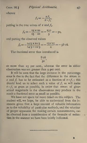
CHAP. III.] Physical Arithmetic. 49
whence
putting in the true values of F and/i.
and putting the observed values
7 14-5x10-5 = _i5^514-5-10-5 4
The fractional error thus introduced is
8-06
or more than 25 per cent., whereas the error in either
observation was not greater than 5 per cent.
It will be seen that the large increase in the percentageerror is due to the fact that the difference in the errors in
F and/! has to be estimated as a fraction of F/", ;
this
should lead us to select such a value of /i as will makeF /i as great as possible, in order that errors of givenactual magnitude in the observations may produce in the
result a fractional error as small as possible.
We have not space for more detail on this subject. Thestudent will, we hope, be able to understand from the in-
stances given that a large amount of valuable information
as to the suitability of particular methods, and the selectior
of proper apparatus for making certain measurements, can
be obtained from a consideration of the formulae of reduc-
tion in the manner we have here briefly indicated.
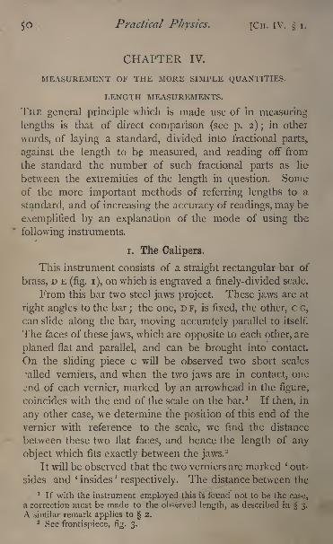
$0 Practical Physics. [Cn. IV. i.
CHAPTER IV.
MEASUREMENT OF THE MORE SIMPLE QUANTITIES.
LENGTH MEASUREMENTS.
THE general principle which is made use of in measuring
lengths is that of direct comparison (see p. 2); in other
words, of laying a standard, divided into fractional parts,
against the length to be measured, and reading off from
the standard the number of such fractional parts as lie
between the extremities of the length in question. Someof the more important methods of referring lengths to a
standard, and of increasing the accuracy of readings, may be
exemplified by an explanation of the mode of using the
following instruments.
i. The Calipers.
This instrument consists of a straight rectangular bar of
brass, D E (fig. i), on which is engraved a finely-divided scale.
From this bar two steel jaws project. These jaws are at
right angles to the bar;the one, D F, is fixed, the other, c G,
can slide along the bar, moving accurately parallel to itself.
The faces of these jawr
s, which are opposite to each other, are
planed flat and parallel, and can be brought into contact.
On the sliding piece c will be observed two short scales
called verniers, and when the two jaws are in contact, one
^nd of each vernier, marked by an arrowhead in the figure,
coincides with the end of the scale on the bar. 1 If then, in
any other case, we determine the position of this end of the
vernier with reference to the scale, we find the distance
between these two flat faces, and hence the length of any
object which fits exactly between the jaws.-
It will be observed that the two verniers are marked '
out-
sides and ' insidesJ
respectively. The distance between the
1 If with the instrument employed this is found not to be the case,a correction must be made to the observed length, as described in 3.
A similar remark applies to 2.2 See frontispiece, fig. 3.
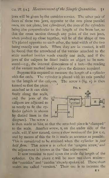
Cn. IV. i.]Measurement of the Simple Quantities. 5 1
FIG. i.
jaws will be given by the outsides vernier. The other pair of
faces of these two jaws, opposite tc the two plane parallel
ones, are not plane, but cylindrical, the axes of the cylinders
being also perpendicular to the length of the brass bar, so
that the cross section through any point of the two jaws,
when pushed up close together, will be of the shape of two
U's placed opposite to each other, the total width of the two
being exactly one inch. When they are in contact, it will
be found that the arrowhead of the vernier attached to the
scale marked insides reads exactly one inch, and if the
jaws of the calipers be fitted inside an object to be mea-
sured e.g., the internal dimensions of a box the readingof the vernier marked insides gives the distance required.
Suppose it is required to measure the length of a cylinderwith flat ends. The cylinder is placed with its axis parallel
to the length of the calipers. The screw A (fig. i) is then
turned so that the piece
attached to it can slide
freely along the scale,
and the jaws of the
calipers are adjusted so
as nearly to fit the cy-
linder (which is shown
by dotted lines in the
diagram). The screw A
is then made to bite, so that the attached piece is'
clamped'
to the scale. Another screw, B, on the under side of the
scale, will, if now turned, cause a slow motion of the jaw c G,
and by means of this the fit is made as accurate as possible.
This is considered to be attained when the cylinder is just
held firm. This screw B is called the '
tangent screw,' and
the adjustment is known as the 'fine adjustment.'
It now remains to read upon the scale the length of the
cylinder. On the piece c will be seen two short scales
the ' outsides' and ' insides
'
already spoken of. These short
scales are called'
verniers.' Their use is to increase the
2
-1
52 Practical Physics. [Cn. IV. i.
accuracy of the reading, and may be explained as follows :
suppose that they did not exist, but that the only mark on
the piece c was the arrowhead, this arrowhead would in all
probability lie between two divisions on the large scale.
The length of the cylinder would then be less than that
corresponding to one division, but greater than that corre-
sponding to the other. For example, let the scale be actually
divided into inches, these again into tenths of an inch, and
the tenths into five parts each ; the small divisions will
then be ^ inch or -02 inch in length. Suppose that the
arrowhead lies between 3 and 4 inches, between the third
and fourth tenth beyond the 3, and between the first and
second of the five small divisions, then the length of the
cylinder is greater than S + T^+^OJ i-e - >3'3 2 inches, but
less than 3 + yV+ ^V> i- e - <3'34 inches. The vernier
enables us to judge very accurately what fraction of one
small division the distance between the arrowhead and the
next lower division on the scale is. Observe that there
are twenty divisions on the vernier,1 and that on careful ex-
amination one of these divisions coincides more nearly than
any other with a division on the large scale. Count which
division of the- vernier this is say the thirteenth. Then,as we shall show, the distance between the arrowhead and
the next lower division is -JJ of a small division, that is
T-o"<hy='OI 3 inch, and the length of the cylinder is therefore
3+A+A+Tiiw=3 >
32 + -oi3=3<
333 inch.
We have now only to see why the number representing
the division of the vernier coincident with the division
of the scale gives in thousandths of an inch the distance
between the arrowhead and the next lower division.
Turn the screw-head B till the arrowhead is as nearly
coincident with a division on the large scale as you can
make it. Now observe that the twentieth division on the
vernier is coincident with another division on the large
scale, and that the distance between this division and the
first is nineteen small divisions. Observe also that no other1 Various forms of vernier are figured in the frontispiece.
CH. IV. i.] Measurement of the Simple Quantities. 5 3
divisions on the two scales are coincident. Both are evenlydivided
;hence it follows that twenty divisions of the
vernier are equal to nineteen of the scale that is, one
division on the vernier is -J-|ths of a scale division, or that
one division on the vernier is less than one on the scale by
Jo-th of a scale division, and this is -nnjffti1 of an inch. 1
Now in measuring the cylinder we found that the
thirteenth division of the vernier coincided with a scale divi-
sion. Suppose the unknown distance between the arrowhead
and next lower division is x. The arrowhead is marked o
on the vernier. The division marked i will be nearer the
next lower scale-division by irnroth of an inch, for a
vernier division is less than a scale division by this amount.
Hence the distance in inches between these two divisions,
the one on the vernier and the other on the scale, will be
^ ~~TTJTFO"'
The distance between the thirteenth division of the vernier
and the next lower scale division will similarly be
x ~~TOO &
But these divisions are coincident, and the distance between
them is therefore zero;that is ^=T
i--. Hence the rule
which we have already used.
The measurement of the cylinder should be repeated
four times, and the arithmetic mean taken as the final value.
The closeness of agreement of the results is of course a test
of the accuracy of the measurements.
The calipers may also be used to find the diameter of the
cylinder. Although we cannot here measure surfaces which
are strictly speaking flat and parallel, still the portions of the
surface which are touched by the jaws of the calipers are very
nearly so, being small and at opposite ends of a diameter.
Put the calipers on two low supports, such as a pair of
glass rods of the same diameter, and place the cylinder on
end upon the table. Then slide it between the jaws of the
1
Generally, if n divisions of the vernier are equal to n I of the
scale, then the vernier reads to i/th of a division of the scale.
54 Practical Physics. [CH. IV. 2.
calipers, adjusting the instrument as before by means of the
tangent screw, until the cylinder is just clamped. Repeatthis twice, reading the vernier on each occasion, and takingcare each time to make the measurement across the same
diameter of the cylinder.
Now take a similar set of readings across a diameter at
right angles to the former.
Take the arithmetic mean of the different readings, as
the result.
Having now found the diameter, you can calculate the
area of the cross section of the cylinder. For this area is
,d being the diameter.
4The volume of the cylinder can also be found by
multiplying the area just calculated by the length of the
cylinder.
Experiments.
Determine the dimensions (i) of the given cylinder, (2) of
the given sphere. Enter results thus :
1. Readings of length of cylinder, of diameter.
3-333 in. D}am r J1-301 in.
3332 (1303
3-334 Diam . 2 J 1-303
3334 11302
Mean 3-3332,, Mean 1-3022,,
Area = i'33 1 8 sq. in.
Volume 4*4392 cu. in.
2. Readings of diameter of sphere.
Diam. i 5-234 in.
2 5-233
3 5-232
4 5^33
Mean 5-233
2. The Beam-Compass.
The beam-compass, like the calipers, is an instrument
for measuring lengths, and is very similar to them in con-
struction, consisting essentially of a long graduated beam
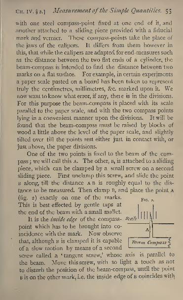
Cn. IV. 2.] Measurement of the Simple Quantities. 55
with one steel compass-point fixed at one end of it, and
;another attached to a sliding piece provided with a fiducial
mark and vernier. These compass-points take the place of
the jaws of the calipers. It differs from them however in
this, that while the calipers are adapter! for end-measures such
as the distance between the two flat ends of a cylinder, the
beam-compass is intended to find the distance between two
marks on a flat surface. For example, in certain experimentsa paper scale pasted on a board has been taken to represent
truly the centimetres, millimetres, &c. marked upon it. Wenow want to know what error, if any, there is in the divisions.
For this purpose the beam-compass is placed with its scale
parallel to the paper scale, and with the two compass points
lying in a convenient manner upon the divisions. It will be
found that the beam-compass must be raised by blocks of
wood a little above the level of the paper scale, and slightly
tilted over till the points rest either just in contact with, or
just above, the paper divisions.
One of the two points is fixed to the beam of the com-
pass ;we will call this A. The other, B, is attached to a sliding
piece, which can be clamped by a small screw on a second
sliding piece. First unclamp this screw, and slide the point
B along, till the distance A B is roughly equal to the dis-
tance to be measured. Then clamp B, and place the point A
(fig. 2) exactly on one of the marks.FIG 2
This is best effected by gentle taps at
the end of the beam with a small mallet.
It is the inside edge of the compass-
point which has to be brought into co-
incidence with the mark. Now observe
that, although B is clamped it is capable
of a slow motion by means of a second
screw called a *
tangent screw,' whose axis is parallel to
the beam. Move this screw, with so light a touch as not
to disturb the position of the beam-compass, until the point
B is on the other mark, i.e. the inside edge of B coincides with
56 Practical Physics. [CH. IV. 2.
the division in question. Suppose that the point A is on the
right-hand edge of the paper scale division, then B should
also be on the right-hand edge of the corresponding division.
To ensure accuracy in the coincidence of the edges youmust use a magnifying-glass.
You have now only to read the distance on the beam-
scale. To do this observe what are the divisions between
which the arrowhead of the vernier1
falls. Then the reading
required is the reading of the lower of these divisions +the reading of the vernier. The divisions are each i milli-
metre. Hence, if the arrowhead falls between the i25thand 1 2 6th, the reading is 125 mm. -f the reading of the
vernier.
Observe which division of the vernier is in the same
straight line with a division of the scale. Suppose the 7th to
be so situated. Then the reading of the vernier is T7g mm.
and the distance between the points is 125-7 mm.
Repeat the observation twice, and suppose that 125*6
and 125-7 are the readings obtained, the mean of the three
will be 125-66, which may be taken as the true distance
between the marks in question.
Suppose that on the paper scale this is indicated by126 mm., then to make the scale true we must reduce the
reading by -34 mm. This is the scale correction for this
division.
Experiment. Check by means of the beam-compass the
accuracy of the divisions of the given centimetre scale.
Enter results thus :
Division of scale at Division of scale at Vernier readingswhich A is placed which B is placed (mean of 3 obs.)
o i cm. 1-005 cm.
2 2-010
3 3"0io
4 ,, 4-015
5 5*oi5 -
etc.
* 55ee frontispiece, fie. z.
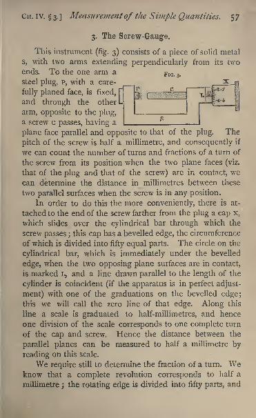
CH. IV. 3. ]Measurement of the Simple Quantities. 5 7
3. The Screw-Gauge.
This instrument (fig. 3) consists of a piece of solid metal
s, with two arms extending perpendicularly from its two
ends. To the one arm a FlG>
steel plug, p, with a care-
fully planed face, is fixed, [~
and through the other L
arm, opposite to the plug,
a screw c passes, having a
plane face parallel and opposite to that of the plug. The
pitch of the screw is half a millimetre, and consequently if
we can count the number of turns and fractions of a turn of
the screw from its position when the two plane faces (viz.
that of the plug and that of the screw) are in contact, we
can determine the distance in millimetres between these
two parallel surfaces when the screw is in any position.
In order to do this the more conveniently, there is at-
tached to the end of the screw farther from the plug a cap x,
which slides over the cylindrical bar through which the
screw passes ;this cap has a bevelled edge, the circumference
of which is divided into fifty equal parts. The circle on the
cylindrical bar, which is immediately under the bevelled
edge, when the two opposing plane surfaces are in contact,
is marked L, and a line drawn parallel to the length of the
cylinder is coincident (if the apparatus is in perfect adjust-
ment) with one of the graduations on the bevelled edge;this we will call the zero line of that edge. Along this
line a scale is graduated to half-millimetres, and hence
one division of the scale corresponds to one complete turn
of the cap and screw. Hence the distance between the
parallel planes can be measured to half a millimetre by
reading on this scale.
We require still to determine the fraction of a turn. Weknow that a complete revolution corresponds to half a
millimetre ; the rotating edge is divided into fifty parts, and
58 Practical Physics. [Cn. IV. 3.
therefore a rotation through a single part corresponds to a
separation of the parallel planes by T J-^ mm. Suppose, then,
that the scale or line along which the graduations on the
cylinder are marked, cuts the graduations on the edge of the
cap at 1 2 '2 divisions from the zero mark;then since, when a
revolution is complete, the zero mark is coincident with the
line along which the graduations are carried on the cylinder,
the distance between the parallel planes exceeds the numberof complete revolutions read on that scale by -^2 ths of a
turn, i.e. by -122 mm.If then we number every tenth division on the bevelled
edge successively i, 2, 3, 4, 5, these numbers will indicate
tenths of a millimetre; 5 of them will be a complete turn,
and we must go into the next turn for 6, 7, 8, 9 tenths
of a millimetre. It will be noticed that on the scale gradu-ated on the fixed cylinder the smaller scratches correspondto the odd half-millimetres and the longer ones to the com-
plete millimetres. And on the revolving edge there are two
series of numbers, i, 2, 3, 4, 5 inside, and 6, 7, 8, 9, 10 out-
side. A little consideration will shew that the number to be
taken is the inside or the outside one according as the last
visible division on the fixed scale is a complete millimetre
division or an odd half-millimetre division.
We can therefore read by this instrument the distance
between the parallel planes to y-J-^th of a millimetre, or by
estimating the tenth of a division on the rotating edge to
the TuVotn f a millimetre.
We may use the instrument to measure the length of a
short cylinder thus. Turn the screw-cap, holding it quite
lightly, so that, as soon as the two parallel planes touch, the
fingers shall slip on the milled head, and accordingly shall
not strain the screw by screwing too hard. 1 Take a reading
when the two planes are in contact; this gives the zero read-
1
Special provision is made for this in an improved form of this
apparatus. The milled head is arranged so that it slips past a rntchet
wheel whenever the pressure on the screw-face exceeds a certain limit,
CH. IV. 4.] Measurement of the Simple Quantities. 59
ing, which must be added to any observation reading if the
zero of the scale has been passed, subtracted if it has not been
reached. Then separate the planes and introduce the
cylinder with its ends parallel to those of the gauge, and
screw up again, holding the screwhead as nearly as possible
with the same grip as before, so that the ringers shall slip
when the pressure is as before. Then read off on the scales.
Add or subtract the zero correction as the case may be;
a reading of the length of the cylinder is thus obtained.
Read the zero again, and then the length of the cylinder at
a different part of the area of the ends, and so on for ten
readings, always correcting for the zero reading.
Take the mean of the readings for the length of the
cylinder, and then determine the mean diameter in the same
way.
The diameter of a wire may also conveniently be found
by this instrument.
The success of the method depends on the touch of the
screwhead, to make sure that the two planes are pressed
together for the zero reading with the same pressure as whenthe cylinder is between them.
Be careful not to strain the screw by screwing too hard.
Experiment. Measure the length and diameter of the givensmall cylinder.
Enter result thus :
Correction for zero + "0003 cm.
Length (mean of ten) '9957
True length -9960
4. The Spherometer.
The instrument consists of a platform with three feet,
whose extremities form an equilateral triangle, and in the
middle of the triangle is a fourth foot, which can be raised or
lowered by means of a micrometer screw passing perpendi-
cularly through the centre of the platform, The readings
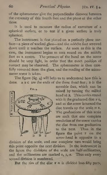
6o Practical Physics. [CH. IV. 4.
of the spherometer give the perpendicular distance between
the extremity of this fourth foot and the plane of the other
three.
It is used to measure the radius of curvature of a
spherical surface, or to test if a given surface is truly
spherical.
The instrument is first placed on a perfectly plane sur-
face a piece of worked glass and the middle foot screwed
down until it touches the surface. As soon as this is the
case, the instrument begins to turn round on the middle
foot as a centre. The pressure of the hand on the screw
should be very light, in order that the exact position of
contact may be observed. The spherometer is then care-
fully removed from the glass, and the reading of the micro-
meter screw is taken.
The figure (fig. 4) will help us to understand how this is
done. ABC are the ends of the three fixed feet;D is the
movable foot, which can be
raised by turning the milled
head at E. This carries round
with it the graduated disc F G,
and as the screw is turned the
disc travels up the scale H K.
The graduations of this scale
are such that one completerevolution of the screw carries
the disc from one graduation
to the next. Thus in the
figure the point F on the
screw-head is opposite to a
division of the scale, and one complete turn would bring
this point opposite the next division. In the instrument in
the figure the divisions of the scale are half-millimetres,
and the millimetres are marked o, i, 2. Thus only every
second division is numbered.
But the rim of the disc F o is divided into fifty parts,
FIG. 4.
CH. IV. 4.] Measurement of the Simple Quantities. 6 1
and each of these subdivided into ten. Let us suppose that
division 12 of the disc is opposite to the scale at F, and
that the milled head is turned until division 36 comes oppo-site. Then the head has been turned through 24 (i.e. 36 1 2)
larger divisions;but one whole turn or fifty divisions carry
the point D through \ mm. Thus a rotation through
twenty-four divisions will carry it through |-J of \ mm. or
24 mm.Hence the larger divisions on the disc F G correspond
to tenths of a millimetre, and these are subdivided to
hundredths by the small divisions.
Thus we might have had opposite to the scale in the
first instance 12 6 large divisions, and in the second 36*9.
Then the point D would have moved through "243 mm.It will be noticed that in the figure division o is in
the centre of the scale H K, which is numbered i, 2, 3, &c.,
from that point in both directions up and down. Thedivisions numbered on the disc F G are the even ones *
2,
4, 6, &c. and there are two numbers to each division.
One of these numbers will give the parts of a turn of the
screw when it is turned so as to lower the point D, the other
when it is turned so as to raise D. Thus in the figure 1 2
and 38 are both opposite the scale, and in the second
position, 36 and 14. We have supposed the head to be
turned in such a way that the point D has been lowered
through -24 mm. If the rotation had been'in the opposite
direction, D would have been raised through 0*26 mm.Let us for the present suppose that all our readings are
above the zero of the scale.
To take a reading we note the division of the scale next
above which the disc stands, and then the division of the
disc which comes opposite to the scale, taking care that wetake the series of divisions of the disc which correspondsto a motion of the point D in the upward direction the
1 These numbers are not shewn in the figure.
62 Practical Physics. [CH. IV. 4.
inner ring of numbers in the figure. Thus the figured
reading is 1*380.
If the instrument were in perfect order, the readingwhen it rested on a plane surface would be o o. This is
not generally the case, so we must observe the reading onthe plane. This observation should be made four times,
and the mean taken. Let the result be -460. Now take the
instrument off the plane and draw the middle foot back
some way. We will suppose we are going to measure the
radius of a sphere from the convex side.
Place the instrument on the sphere and turn the
screw E until D touches the sphere. The position of contact
will be given as before, by noticing when the instrument
begins to turn round D as a centre.
Read the scale and screw-head as before;
let the scale
reading be :
2*5 ;and the disc -235.
Then the reading is 2*735
Take as before four readings.
We require the distance through which the point Dhas been moved. This is clearly the difference between the
two results, or 2735 -460 ;if .we call this distance a we
have
a 2*275 mm -
It may of course happen that the reading of the instru-
ment when on the plane is below the zero;
in this case to
find the distance a we must add the two readings.
We must now find the distance in millimetres between
the feet AB or AC. We can do this directly by means of
a finely divided scale;or if greater accuracy is required, lay
the instrument on a flat sheet of card or paper, and press it
so as to mark three dots on the paper, then measure the
distance between these dots by the aid of the beam-
compass ( 2).
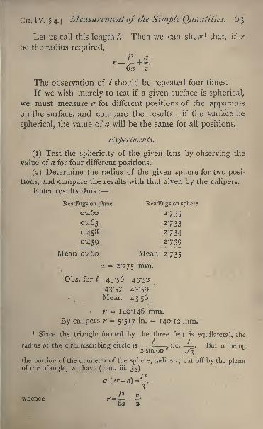
CH. IV. 4.] Measurement of the Simple Quantities. 63
Let us call this length /. Then we can shew '
that, ii" r
be the radius required,
The observation of / should be repeated four times.
If we wish merely to test if a given surface is spherical,
we must measure a for different positions of the apparatus
on the surface, and compare the results;
if the surface be
spherical, the value of a will be the same for all positions.
Experiments.
(1) Test the sphericity of the given lens by observing the
value of a for four different positions.
(2) Determine the radius of the given sphere for two posi-
tions, and compare the results with that given by the calipers.
Enter results thus :
Readings on plane Readings on sphere
0-460 2735
0-463 2733
0-458 2734Q'459 _27_39
Mean 0-460 Mean 2-735
a = 2-275 mm '
Obs. for / 43*56 43-52
43-57 43-59Mean 43^56
r = 140-146 mm.
By calipers r 5-517 in. = 140-12 mm.
1 Since the triangle formed by the three feet is equilateral, the
radius of the circumscribing circle is .--.i.e. . But a beinir
2 sin 60 ^3-the portion of the diameter of the sphere, radius r, cut off by the planeof the triangle, we have (Euc. iii. 35)
whence r= -^- + -6a 2

64 Practical Physics. [CH. IV. 5.
5. Measurement of a Base-Line.
The object of this experiment, which is a working modelof the measurement of a geodetic base-line, is~to determine
with accuracy the distance between the scratches on two
plugs so far apart that the methods of accurate measurementdescribed above are impracticable.
i ne general plan of the method is to lay ivory scales
end to end, fixing them by placing heavy weights on them,and to read by means of a travelling reading microscope the
distance between the extreme graduations of the two ivory
scales, or between the mark on the plug and the extreme
graduation of the ivory scale placed near it. We have then
to determine the real length of the ivory scales, and by add-
ing we get the total length between the plugs.
The experiment may therefore be divided into three
parts.
(i). To determine the Distance between the End Gradu-
ations of the Ivory Scales placed end to end.
This is done by means of the travelling microscope. Place
the scales with their edges along a straight line drawn between
the two marks and perpendicular to them, and fix them so
that the extreme graduations are within \ inch. Next place
the microscope (which is mounted on a slide similar to the
slide-rest of a lathe, and moved by a micrometer screw the
thread of which we will suppose is -sVn f an mcn)
s tna^
the line along which it travels on its stand is parallel to the
base line, and focus it so that one of its cross-wires is
parallel and coincident with one edge of the image of the
end graduation of the one ivory scale. (It is of no conse-
quence which edge is chosen, provided it be always the same
in each case.)
Read the position of the microscope by its scale and
micrometer screw, remembering that the fixed scale along
which the divided screw-head moves is graduated to 5oths
of an inch, and the circumference of the screw-head into
CH. IV. 5.] Measurement of the Simple Quantities. 65
200 parts j each part corresponds, therefore, to T^Urr incn -
So that if the reading on the scale be 7, and on the screw-
head 152, we get for the position
7 divisions of the scale=/^-in. =0-14 in.
152 divisions of the screw-head =0-0152 in.
Reading=o-i552in.
Or if the scale reading be 5 and the screw-head read-
ing 15, the reading similarly is 0-1015 in.
Next turn the micrometer screw-head until the last
division on the other ivory scale comes into the field of
view, and the corresponding edge of its image is coincident
with the cross-wire as before. Read again ;the difference of
the two readings gives the required distance between the two
graduations.
In the same way the distance between the scratch on the
plug and the end division of the scale maybe determined.
Place one -ivory scale so that one extremity is near to
or coincident with the scratch on the plug ;read the dis-
tance between them;then place the other scale along the
line and end-on with the first, and measure the distance
between the end divisions of the two scales. Then transfer
the first scale to the other end of the second ; measure the
distance between them again ;and so on.
(2). To Estimate the Fraction of a Scale over.
This may be done by reading through the microscopethe division and fraction of a division of the scale corre-
sponding to the scratch on the second plug. This gives the
length of a portion of the scale as a fraction of the true
length which is found in (3).
(3). To Determine the true Length of the Ivory Scales.
This operation requires two reading microscopes. Focus
these two, one on each extreme division of the scales to be
measured, taking care that the same edge of the scratch
is used as before. Then remove the scale, introduce a
standard whose graduation can be assumed to be accurate,
F
66 Practical Physics. [CH. IV. 5.
or whose true length is known, and read by means of the
micrometer the exact length, through which the microscopeshave to be moved in order that their cross-wires may co-
incide with two graduations on the standard the distance
between which is known accurately.1
The lengths of all the separate parts of the line between
the marks, which together make up the whole distance to
be measured have thus been expressed in terms of the
standard or of the graduations of the micrometer screw.
These latter may be assumed to be accurate, for they are
only used to measure distances which are themselves small
fractions of the whole length measured (see p. 41). All the
data necessary to express the whole length in terms of the
standard have thus been obtained.
Experiment. Measure by means of the two given scales
and the microscope the distance between the two given points.
Enter the results thus :
Distance from the mark on first plug to the end
graduation of Scale A 0-1552 in.
Distance between end graduations of ScalesAand B(i) 0-1015
(2) 0-0683
(3) Q'0572
i} (4) 0-1263
(5) 0-1184,,
Total of intervals .... -6269 in.
Reading of Scale B at the mark on the second plug . 10-631
True length of Scale A 12-012,,
B n'993,,Total distance between the marks
= 3 x 12-012 + 2 x 1 1*993 + 10-631 + 0-6269= 71-280 in.
6. The Kathetometer.
This instrument consists ot a vertical beam carrying a
scale. Along the scale there slides a brass piece, support-
ing a telescope, the axis of which can be adjusted so as
to be horizontal. The brass slide is fitted with a vernier1 For less accurate measurements the lengths of the scales may also
be determined by the use of the beam -compass 2.
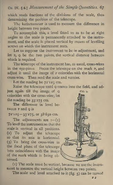
CH. IV. 6.] Measurement of the Simple Quantities. 67
FIG. 5.
which reads fractions of the divisions of the scale, thus
determining the position of the telescope.
The kathetometer is used to measure the difference in
height between two points.
To accomplish this, a level fitted so as to be at right
angles to the scale is permanently attached to the instru-
ment, and the scale is placed vertical by means of levelling
screws on which the instrument rests.
Let us suppose the instrument to be in adjustment, and
let p, Q be the two points, the vertical distance between
which is required.
The telescope of the instrument has, as usual, cross-wires
in the eye-piece. Focus the telescope on the mark p, and
adjust it until the image of P coincides with the horizontal
cross-wire. Then read the scale and vernier.
Let the reading be 72*125 cm.
Raise the telescope until Q comes into the field, and ad-
just again till the image of Qcoincides with the cross-wire; let
the reading be 33*275 cm.
The difference in level be-
tween p and Q is
7 2'
12 5 33'2 75> or 38>85 cm -
The adjustments are : (i)
To level the instrument so that the
scale is vertical in all positions.
(2) To adjust the telescopeso that its axis is horizontal.
(3) To bring the cross-wire in
the focal plane of the telescopeinto coincidence with the imageof the mark which is being ob-
served.
(i) The scale must be vertical, because we use the instru-
ment to measure the vertical height between two points.The scale and level attached to it (fig. 5) can be turned
F 2
68 Practical Physics. [CH. IV. 6.
round an axis which is vertical when properly adjusted,
carrying the telescope with them, and can be clamped in
any position by meatis cf a screw.
(a) To test the Accuracy of the Setting of the Scale-level
and to set the Axis ofRotation vertical.
If the scale-level is properly set it is perpendicular to
t.he axis of rotation;to ascertain whether or not this is so,
turn the scale until its level is parallel to the line joining
two of the foot screws and clamp it; adjust these screws
until the bubble of the level is in the middle. Unclamp, and
turn the scale round through 180. If the bubble is still in
the middle of the level, it follows that this is at right anglesto the axis of rotation
;if the bubble has moved, then the
level and the axis of rotation are not at right angles. Wemay make them so by adjusting the screws which fix the
level to the instrument until the rotation through 180
produces no change, or, without adjusting the level, we mayproceed to set the axis of rotation vertical if, instead of
adjusting the levelling screws of the instrument until the
bubble stands in the centre of the tube, we adjust them until
the bubble does not move relatively to the tube when the
instrument is turned through 180.
This having been secured by the action of two of the
screws, turn the scale until the level is at right angles to
its former position and clamp. Adjust now in the same
manner as before, using only the third screw.
It follows then that the bubble will remain unaltered
in position for all positions of the instrument, and that the
axis about which it turns is vertical.
If the scale of the instrument were parallel to the axis,
it, too, would be vertical, and the instrument would be in
adjustment.
(b) To set the Scale vertical.
To do this there is provided a metallic bracket-piece.
One arm of this carries a level, while the other is a flat
surface at right angles to the axis of the level, so that when
CH. iv. 6.] Measurement of the Simple Quantities. 69
the level is horizontal this surface is truly vertical. The
adjustment can be tested in the following manner. Thelevel can rotate about its axis, and is weighted so that the
same part of the tube remains uppermost as the bracket is
rotated about the axis of the level. Place then the flat face
of the bracket with the level uppermost against a nearly
vertical plane surface;notice the position of the bubble.
Then reverse it so that the level is lowest, and read the posi-
tion of the bubble again. If it has not changed the level
is truly set, if any displacement has taken place it is not so.
The scale of the instrument can be adjusted relatively
to the axis of rotation and fixed by screws.
Press the flat surface of the bracket-piece against the
face of the scale. If the scale be vertical, the bubble of the
level on the bracket-piece will occupy the middle of its
tube. Should it not do so, the scale must be adjusteduntil the bubble comes to the central position. We are
thus sure that the scale is vertical.
For ordinary use, with a good instrument, this last ad-
justment may generally be taken as made.
Now turn the telescope and, if necessary, raise or lower
it until the object to be observed is nearly in the middle
of the field of view.
(2) It is necessary that the axis of the telescope should
be always inclined to the scale at the same angle, for if,
when viewing a second point Q, the angle between the
axis and the scale has changed from what it was in viewing
p, it is clear that the distance through which the telescope
has been displaced will not be the vertical distance between
p and Q.
If, however, the two positions of the axis be parallel,
the difference of the scale readings will give us the distance
we require.
Now the scale itself is vertical. The safest method,
therefore, of securing that the axis of the telescope shall
be always inclined at the same angle to the scale is to adjust
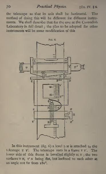
Practical Physics. [Cn. IV. 6.
the telescope so that its axis shall be horizontal. Themethod of doing this will be different for different instru-
ments. We shall describe that for the one at the Cavendish
Laboratory in full detail;the plan to be adopted for other
instruments will be some modification of this.
FIG.
In this instrument (fig. 6) a level L M is attached to the
telescope T T'. The telescope rests in a frame Y Y'. Thelower side of this frame is bevelled slightly at N
; the two
surfaces Y N, Y' N being flat, but inclined to each other at
an angle not far from 180.
CM. IV. 6.] Measurement of the Simple Quantities. 71
This under side rests at N on a flat surface c D, which is
part of the sliding-piece c D, to which the vernier v v'
is fixed.
A screw passes through the piece Y Y' at N, being fixed
into c D. The hole in the piece Y Y' is large and somewhat
conical, so that the telescope and its support can be turned
about N, sometimes to bring N Y into contact with c N,
sometimes to bring N Y' into contact with N D.
Fitted into c D and passing freely through a hole in N Y'
is a screw Q ;p is another screw fitted into c D, which
bears against N Y'. Hidden by P and therefore not shown in
the figure is a third screw just like p, also fitted into c D, and
bearing against N Y'. The screws N, p, and Q can all be
turned by means of a tommy passed through the holes
in their heads. When p and Q are both screwed home,the level and telescope are rigidly attached to the sliding-
piece c D.
Release somewhat the screw Q. If now we raise the
two screws p, we raise the eye-piece end of the telescope,
and the level-bubble moves towards that end. If we lower
the screws p, we lower the eye-piece end, and the bubble
moves in the opposite direction.
Thus the telescope can be levelled by adjusting the
screws P. Suppose the bubble is in the centre of the level.
Screw down the screw Q. This will hold the telescope
fixed in the horizontal position.
If we screw Q too firmly down, we shall force the piece
N Y' into closer contact with the screws P, and lower the
eye-piece end. It will be better then to adjust the screw
p so that the bubble is rather too near that end of the tube.
Then screw down Q until it just comes to the middle of the
tube, and the telescope is level.
(3) To bring the image of the object viewed to coincide
with the cross-wires.
The piece c D slides freely up and down the scale. EF F'E'
is another piece of brass which also slides up and down.
72 Practical Physics. [CH. IV. 6.
H is a screw by means of which E F' can be clamped fast
to the scale. A screw R R' passes vertically upwards throughE F' and rests against the under side of a steel pin G fixed
in c D. Fixed to EF' and pressing downwards on the pin G
so as to keep it in contact with the screw R R' is a steel springs s'. By turning the screw R R', after clamping H, a small
motion up or down can be given to the sliding piece c Dand telescope.
Now loosen the screw H and raise or lower the two
pieces c D, E F' together by hand, until the object viewed is
brought nearly into the middle of the field of view. Then
clamp E F' by the screw H.
Notice carefully if this operation has altered the level of
the telescope ;if it has, the levelling must be done again.
By means of the screw R R' raise or lower the telescopeas may be needed until the image is brought into coincidence
with the cross-wire. Note again if the bubble of the level is
in its right position, and if so read the scale and vernier.
It may happen that turning the screw R R' is sufficient
to change the level of the telescope. In order that the slide
c D may move easily along the scale, a certain amount of
play must be left, and the friction between R' and the pinis sometimes sufficient to cause this play to upset the level
adjustment. The instrument is on this account a trouble-
some one to use.
The only course we can adopt is to level;and then adjust
R R' till the telescope is in the right position, levelling againif the last operation has rendered it necessary.
This alteration of level will produce a small change in
the position of the line of collimation of the telescope rela-
tively to the vernier, and thus introduce an error, unless
the axis round which the telescope turns is perpendicularboth to the line of collimation and to the scale. If, however,the axis is only slightly below the line of collimation and
the change of level small, the error will be very small indeed
and may safely be neglected.
It is clear that the error produced by an error in levelling
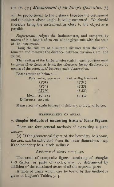
CH IV. 7.] Measurement of the Simple Quantities. 73
will be pioportional to the distance between the instrument
and the object whose height is being measured. We should
therefore bring the instrument as close to the object as is
possible.
Experiment. Adjust the kathetometer, and compare bymeans of it a length of 20 cm. of the given rule with the scale
of the instrument.
Hang the rule up at a suitable distance from the kathe-
tometer, and measure the distance between division 5 cm. and
25 cm.
The reading of the kathetometer scale in each position must
be taken three times at least, the telescope being displaced bymeans of the screw R R' between each observation.
Enter results as below :
Kath. reading, upper mark Kath. reading, lower mark
253I5
25305
25^20
Mean 25-3133Difference 20-0167
Mean error of scale between divisions 5 and 25, -0167 cm.
MEASUREMENT OF AREAS.
7. Simpler Methods of measuring Areas of Plane Figures.
There are four general methods of measuring a planearea:
(a) If the geometrical figure of the boundary be known,the area can be calculated from its linear dimensions e.g.
if the boundary be a circle radius r.
Area= TT r* where TT 3*142.
The areas of composite figures consisting of triangles
and circles, or parts of circles, may be determined byaddition of the calculated areas of all the separate parts.
A table of areas which can be found by this method is
given in Lupton's Tables, p. 7.
74 Practical Physics. [Cn. IV. 7.
In case two lengths have to be measured whose productdetermines an area, they must both be expressed in the
same unit, and their product gives the area expressed in
terms of the square of that unit.
(b) If the curve bounding the area can be transferred to
paper divided into known small sections, e.g. square milli-
metres, the area can be approximately determined by count-
ing up the number of such small areas included in the
bounding curve. This somewhat tedious operation is facili-
tated by the usual grouping of the millimetre lines in tens,
every tenth line being thicker. In case the curve cuts a
square millimetre in two, the amount must be estimated;
but it will be generally sufficient if portions greater than a
half be reckoned a whole square millimetre and less than a
half zero.
(c) By transferring the curve of the boundary to a sheet
of paper or metal of uniform thickness and cutting it out,
and cutting out a square of the same metal of known length
of side, say 2 inches, and weighing these two pieces of metal.
The ratio of their weights is the ratio of the areas of the two
pieces of metal. The one area is known and the other maytherefore be determined.
(d) By the planimeter. A pointer is made to travel
round the boundary, and the area is read off directly on the
graduated rim of a wheel.
For the theory of this instrument see Williamson's In-
tegral Calculus ( 149). Practical instructions are issued
by the makers.
Experiment. Draw by means of a compass a circle of 2 in.
radius. Calculate or determine its area in all four ways, and
compare the results.
Enter results thus :
Method a b c. d
12-566 sq. in, 12-555 scl-
in 12-582 sq. in. 12-573 sq. in,
CH. IV. 8.] Measurement of the Simple Quantities. 75
8, Determination of the Area of the Cross-Section of a
Cylindrical Tube, Calibration of a Tube.
The area of the cross-section of a narrow tube is best
determined indirectly from a measurement of the volume of
mercury contained in a known length of the tube. The
principle of the method is given in Section 9. The tube
should first be ground smooth at each end by rubbing on a
stone with emery-powder and water, and then very care-
fully cleaned, first with nitric acid, then with distilled
water, then with caustic potash, and finally rinsed with dis-
tilled water, and very carefully dried by passing air through
it, which has been dried by chloride of calcium tubes. 1 Thedifferent liquids may be drawn up the tube by means
of an air-syringe. If any trace of moisture remain in the
tube, it is very difficult to get all the mercury to run out of
it after it has been filled.
The tube is then to be filled \\ithfltre* mercury ;this is
best done by immersing it in a trough of mercury of the
necessary length. [A deep groove about half an inch broad
cut in a wooden beam makes a very serviceable trough for
the purpose.] When the tube is quite full, close the ends
with the forefinger of each hand, and after the small globules
of mercury adhering to the tube have been brushed off,
allow the mercury to run into a small beaker, or other con-
venient vessel, and weigh it. Let the weight of the mercurybe w. Measure the length of the tube by the calipers or
beam-compass, and let its length be /. Look out in the
table (33) the density of mercury for the temperature (which
may be taken to be that of the mercury in the trough), and
1 For this and a great variety of similar purposes an aspirating
pump attached to the water-supply of the laboratory is very convenient.- A supply of pure mercury may be maintained very conveniently
by distillation under very low pressure in an apparatus designed byWeinhold (see Carl's Rep. vol. 15, and Phil. Mag., Jan., 1884).
76 Practical Physics. [CH. IV. 8.
let this be p. Then the volume v of the mercury is given
by the equation
and this volume is equal to the product of the area A of the
cross-section and the length of the tube. Hence
If the length be measured in centimetres and the weightin grammes, the density being expressed in terms of grammes
per c.c., the area will be given in sq. cm.
The length of the mercury column is not exactly the
length of the tube, in consequence of the fingers closing the
tube pressing slightly into it, but the error due to this cause
is very small indeed.
This gives the mean area of the cross-section, and we
may often wish to determine whether or not the area of the
section is uniform throughout the length. To do this, care-
fully clean and dry the tube as before, and, by partly im-
mersing in the trough, introduce a thread of mercury of anyconvenient length, say about 5 centimetres long. Place the
tube along a millimetre scale, and fix it horizontally so that
the tube can be seen in a telescope placed about six or
eight feet off.
By slightly inclining the tube and scale, adjust the thread
so that one end of it is as close as possible to the end of
the tube, and read its length in the telescope. Displace
the thread through 5 cm. and read its length again ; and so
on, until the thread has travelled the whole length of the
tube, taking care that no globules of mercury are left
behind. Let /1}
72 ,/3 . . . . be the successive lengths of the
thread. Then run out the mercury into a beaker, and
weigh as before. Let the weight be w, and the density of
the mercury be p.
CH. IV. 8.] Measurement of the Simple Quantities. 77
Then the mean sectional areas of the different portions
of the tube are
w w w.. etc.
, -, -,
P i\ P/2 P *3
The mean of all these values of the area should give the
mean value of the area as determined above. The accu-
racy of the measurements may thus be tested.
On a piece of millimetre sectional paper of the same
length as the tube mark along one line the different points
which correspond to the middle points of the thread in its
different positions, and along the perpendicular lines throughthese points mark off lengths representing the correspond-
ing areas of the section, using a scale large enough to shew
clearly the variations of area at different parts of the length.
Join these points by straight lines. Then, the ordinates
of the curve to which these straight lines approximate give
the cross-section of the tube at any point of its length.
Experiment. Calibrate, and determine the mean area of
the given tube.
Enter the result thus :
[The results of the calibration are completely expressed bythe diagram.]
Length of tube . . . .25*31 cm.
Weight of beaker . . . 10-361 gm.
Weight of beaker and mercury . 1 1 786 gm.
Weight of mercury . . 1*425 gm.
Temperature of mercury . '14 C.
Density of mercury (table 33) 13*56
Mean area of section =* ^2 5 Sq. cm.
25*31 x 13-56
= 0*415 sq. mm.
Mean of the five determinations for calibration 0*409 sq. mm.
78 Practical Physics. [CH. IV. 9.
MEASUREMENT OF VOLUMES.
The volumes of some bodies of known shape may be de-
termined further by calculation from their linear dimensions;
one instance of this has been given in the experiment with
the calipers.
A Table giving the relations between the volume and
linear dimensions in those cases which are likely to occur
most frequently will be found in Lupton's Tables, p. 7.
9. Determination of Volumes by Weighing.
Volumes are, however, generally determined from a
knowledge of the mass of the body and the density of the
material of which it is composed. Definingc
density'
as
the mass of the unit of volume of a substance, the relation
between the mass, volume and density of a body is ex-
pressed by the equation M=vp, where M is its mass, v its
volume, and p its density. The mass is determined bymeans of the balance (see p. 91), and the density, which is
different at different temperatures, by one or other of the
methods described below (see pp. 107-1 1 2). The densities of
certain substances of definitely known composition, such as
distilled water and mercury, have been very accurately de-
termined, and are given in the tables (Nos. 32, 33), and need
not therefore be determined afresh on every special occa-
sion. Thus, if we wish, for instance, to measure the volume
of the interior of a vessel, it is sufficient to determine the
amount and the temperature of the water or mercury which
exactly fills it. This amount may be determined by weigh-
ing the vessel full and empty, or if the vessel be so large that
this is not practicable, fill it with water, and run the water
off in successive portions into a previously counterpoised
flask, holding about a litre, and weigh the flask thus filled.
Care must be taken to dry the flask between the successive
fillings ; this may be rapidly and easily done by using a hot
clean cloth. The capacity of vessels of very considerable
CH. IV. 10.] Measurement of the Simple Quantities. 79
size may be determined in this way with very great
accuracy.All the specific gravity experiments detailed below
involve the measurement of a volume by this method.
Experiment. Determine the volume of the given vessel.
Enter results thus :
Weight of water
Filling i . . iooi -2 gms.2 . . 99873 . . 1002-3
4 . . 999-2
5 . . 798-1
Total weight . 4799-5 gms. Tenlperature of water
, Volume. . 4803-5 c.c. in vessel, 1 5.
10. Testing the Accuracy of the Graduation of a Burette,
Suppose the burette to contain 100 c.c.;we will suppose
also that it is required to test the capacity of each fifth of
the whole.
The most accurate method of reading the burette is bymeans of afloat, which consists of a short tube of glass loaded
at one end so as just to float vertically in the liquid in the
burette;round the middle of the float a line is drawn,
and the change of the level of the liquid is determined
by reading the position of this line on the graduations of
the burette. The method of testing is then as follows :
Fill the burette with water, and read the position of the
line on the float. Carefully dry and weigh a beaker, and
then run into it from the burette about th of the whole
contents ; read the position of the float again, and weigh the
amount of water run out into the beaker. Let the number
of scale divisions of the burette be 20-2 and the weight in
grammes 20-119. Read the temperature of the water; then,
knowing the density of water at that temperature (fromtable 32), and that i gramme of water at 4 C. occupies i c,c.,
So Practical Physics. [CH. IV. 10.
we can determine the actual volume of the water correspond-
ing to the 20-2 c.c. as indicated by the burette, and hence
determine the error of the burette. Proceeding in this
way for each -Jth of the whole volume, form a table of cor-
rections.
Experiment. Form a table of corrections for the givenburette.
Enter results thus :
Burette readings Error
0-5 c.c --007 c.c.
S-io . . . . --020
10-15 ,, -'on15-20 . -ooo
20-25 ' -'036
MEASUREMENT OF ANGLES.
The angle between two straight lines drawn on a sheet of
paper may be roughly measured by means of a protractor, a
circle or semi-circle with its rim divided into degrees. Its
centre is marked, and can therefore be placed so as to coin-
cide with the point of intersection of the two straight lines ;
the angle between them can then be read off on the gradua-tions along the rim of the protractor. An analogous methodof measuring angles is employed in the case of a compass-needle such as that required for 69.
The more accurate methods of measuring angles dependon optical principles, and their consideration is accordingly
deferred until the use of the optical instruments is explained
(see 62, 71).
MEASUREMENTS OF TIME.
The time-measurements most frequently required in
practice are determinations of the period of vibration of a
needle. To obtain an accurate result some practice in the
use of the *
eye and ear method '
is required. The experi-
CH. IV. ii.] Measurement of the Simple Quantities. 8 1
ment which follows( n) will serve to illustrate the method
and also to call attention to the fact that for accurate work
any clock or watch requires careful *
rating,' /.*. comparisonof its rate of going with some timekeeper, by which the
times can be referred to the ultimate standard the meansolar day. The final reference requires astronomical obser-
vations.
Different methods of time measurement will be found
in 21 and 28. The 'method of coincidences'
is briefly
discussed in 20.
ii. Rating a Watch by means of a Seconds-Clock.
The problem consists in determining, within a fraction
of a second, the time indicated by the watch at the two
instants denoted by two beats of the clock with a knowninterval between them. It will be noticed that the seconds-
finger of the clock remains stationary during the greater part
of each second, and then rather suddenly moves on to
the next point of its dial. Our object is to determine to
a fraction of a second the time at which it just completesone of its journeys.
To do .this we must employ both the eye and ear, as it is
impossible to read both the clock and watch at the same
instant of time. As the watch beats more rapidly than the
clock, the plan to be adopted is to watch the latter, and
listening to the beating of the former, count along with it
until it can be read. Thus, listening to the ticking of the
watch and looking only at the clock, note the exact instant
at which the clock seconds-finger makes a particular beat,
say at the completion of one minute, and count along with
the watch-ticks from that instant, beginning o, i, 2, 3, 4, . .
and so on, until you have time to look down and identify the
position of the second-hand of the watch, say at the instant
when you are counting 21. Then we know that this time is
2 1 ticks of the watch after the event (the clock-beat) whose
G
82 Practical Physics. [CH. IV. i*.
time we wished to register ;hence if the watch ticks 4
times a second, that event occurred at ^ seconds before we
took the time on the watch.
We can thus compare to within ^ sec. the time as indicated
by the clock and the watch, and if this process be repeated
after the lapse of half an hour, the time indicated by the
watch can be again compared, and the amount gained or
lost during the half-hour determined. It will require a little
practice to be able to count along with the watch.
During the interval we may find the number of ticks
per second of the watch. To do this we must count the
number of beats during a minute as indicated on the clock.
There being 4 or 5 ticks per second, this will be a difficult
operation if we simply count along the whole way; it is there-
fore better to count along in groups of either two or four,
which can generally be recognised, and mark down a stroke
on a sheet of paper for every group completed ;then at the
end of the minute count up the number of strokes ;we can
thus by multiplying, by 2 or 4 as the case may be, obtain the
number of watch-ticks in the minute, and hence arrive at
the number per second.
Experiment. Determine the number of beats per second
made by the watch, and the rate at which it is losing or gaining.
Enter results thus :
No. of watch-ticks per minute, 100 groups of 3 each.
No. of ticks per second, 5.
hr. m. s.
Clock-reading. . . . . . . . n 38 3Estimated watch-reading, n hr. 34 m. and 10 ticks = u 34 2
Difference . 4 I
Clock-reading. . . . . . 12 8 3Estimated watch-reading, I2hr. 4m. and 6 ticks -12 4 1-2
Difference . . . 41-8
Losing rate of watch, I -6 sec. per hour.

CHAPTER V.
MEASUREMENT OF MASS AND DETERMINATION OF
SPECIFIC GRAVITIES.
12. The Balance,
General Considerations.
THE balance, as is well known, consists of a metal beam,
supported so as to be free to turn in a vertical plane about an
axis perpendicular to its length and vertically above its centre
of gravity. At the extremities of this beam, pans arj sus-
pended in such a manner that they turn freely about axes,
passing through the extremities of the beam, and parallel to
its axis of rotation. The axes of rotation are formed by
agate knife-edges bearing on agate plates. The beam is
provided with three agate edges; the middle one, edge down-
wards, supporting the beam when it is placed upon the plates
which are fixed to the pillar of the balance, and those at
the extremities, edge upwards ;on these are supported the
agate plates to which the pans are attached.
The effect of hanging the pans from these edges is that
wherever in the scale pan the weights be placed, the vertical
force which keeps them in equilibrium must pass throughthe knife-edge above, and so the effect upon the balance is
independent of the position of the weights and the same
as if the whole weight of the scale pan and included masses
were collected at some point in the knife-edge from which
the pan is suspended.In order to define the position of the beam of the balance,
a long metal pointer is fixed to it, its length being perpen-
dicular to the line joining the extreme knife-edges. A small
scale is fixed to the pillar of the balance, and the motion of
the beam is observed by noting the motion of the pointer
along this scale. When the balance is in good adjustment,
the scale should be in such a position that the pointer is
G 2
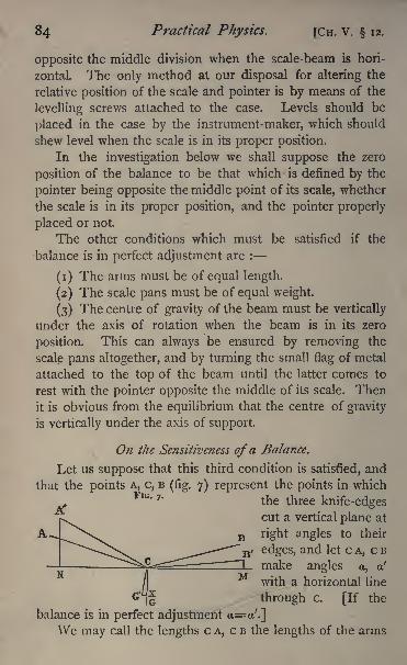
84 Practical Physics. fCn. V. 12.
opposite the middle division when the scale-beam is hori-
zontal. The only method at our disposal for altering the
relative position of the scale and pointer is by means of the
levelling screws attached to the case. Levels should be
placed in the case by the instrument-maker, which should
shew level when the scale is in its proper position.
In the investigation below we shall suppose the zero
position of the balance to be that which is defined by the
pointer being opposite the middle point of its scale, whether
the scale is in its proper position, and the pointer properly
placed or not.
The other conditions which must be satisfied if the
balance is in perfect adjustment are :
(1) The arms must be of equal length.
(2) The scale pans must be of equal weight.
(3) The centre of gravity of the beam must be vertically
under the axis of rotation when the beam is in its zero
position. This can always be ensured by removing the
scale pans altogether, and by turning the small flag of metal
attached to the top of the beam until the latter comes to
rest with the pointer opposite the middle of its scale. Then
it is obvious from the equilibrium that the centre of gravity
is vertically under the axis of support.
On the Sensitiveness ofa Balance.
Let us suppose that this third condition is satisfied, and
that the points A, c, B(fig. 7) represent the points in which
FlG- 7 '
the three knife-edgescut a vertical plane at
right angles to their
edges, and let c A, c B
make angles a, a'
with a horizontal line
^- through c. [If the
balance is in perfect adjustment a==o/.]
We may call the lengths c A, c B the lengths of the arms
CH. V. 12.] Measurement of Mass. 85
of the balance, and represent them by R, L respectively. Let
the masses of the scale pans, the weights of which act ver-
tically downward through A and B respectively, be P and Q.
Let G, the centre of gravity of the beam, be at a distance //,
vertically under c, and let the mass of the beam be K. It
the balance be in adjustment, R is equal to L, and P to Q.
Now let us suppose that a mass w is placed in the scale pan
P, and a mass w+ x in Q, and that in consequence the beamtakes up a new position of equilibrium, arrived at by turning
about c through an angle 6, and denoted by B' c A', and let
the new position of the centre of gravity of the beam be G'.
Then if we draw the vertical lines B' M, A' N to meet the
horizontal through c in M and N, a horizontal line throughG' to meet c G in x, and consider the equilibrium of the
beam, we have by taking moments about the point c
(Q+W+X) CM = (P+ W) CN -f K . G'X.
Nowc M = c B' cos (a' 6) = L (cos a! cos + sin a! sin 6).
c N = c A' cos (a + 6)= R (cos a cos B sin a sin 6).
G' x = c G' sin 6= h sin 0.
Hence we get
L (Q+W+ X) (cos a' cos 0+sin a' sin 6)
=R(P+ W) (cos a cos 6 sin a sin 0) + K/i sin 0.
Since is very small, we may write tan 0=0,
sin a' RP-J-/ sin
This gives us the position in which the balance will rest
when the lengths of the arms and masses of the scale pansare known, but not necessarily equal or equally inclined to
the horizon; and when a difference x exists between the
masses in the scale pans.
It is evident that may be expressed in pointer scale
divisions when the angle subtended at the axis of rotation
Dy one of these divisions is known.
86 Practical Physics. [CH. V. 12.
DEFINITION. The number of scale divisions between
the position of equilibrium of the pointer when the masses
are equal and its position of equilibrium when there is a
given small difference between the masses is called the
sensitiveness of the balance for that small difference. Thus,if the pointer stand at 100 when the masses are equal and
at 67 when there is a difference of *ooi gramme between
the masses, the sensitiveness is 33 per milligramme.We have just obtained a formula by which the sensi-
tiveness can be expressed in terms of the lengths of the
arms, &c.
Let us now suppose that the balance is in adjustment, i.e.
L=R, Q=P, a=a'
L* COS a_
xv
Hence the angle turned through for a given excess weight x
increases proportionally with x, and increases with the lengthof the arm.
Let us consider the denominator of the fraction a little
more closely. We see that it is positive or negative ac-
cording as
K/Z> or <
Now it can easily be shewn that the equation
is the condition that c should be the centre of gravity of the
beam and the weights of the scale pans, &c. supposed col-
lected at the extremities of the arms. If this condition were
satisfied, the balance would be in equilibrium in any position.
If K h be less than L(2P+ 2w+ x) sin a, tan 6 is negative,
which shews that there is a position of equilibrium with the
centre of gravity of the whole, above the axis;but it is
reached by moving the beam in the opposite direction to that
CH. V. 12.] Measurement of Mass. 87
in which the excess weight tends to move it : it is therefore a
position of unstable equilibrium. We need only then discuss
the case in which K h is > L(2P+ 2ze/+#)sino, i.e. when the
centre of gravity of the whole is below the axis of rotation.
With the extreme knife-edges above the middle one,
a is positive and the denominator is evidently diminished,and thus the sensitiveness increased, as the load w increases;
but if the balance be so arranged that a=o, which will be
the case when the three knife-edges are in the same plane,
we have
or the sensitiveness is independent of the load;
if the
extreme knife-edges be below the mean, so that a is nega-
tive, then the denominator increases with the load w,and consequently the sensitiveness diminishes. Now the
load tends to bend the beam a little ;hence in practice, the
knife-edges are so placed that when half the maximum load
is in the scale pans, the beam is bent so that all the knife-
edges lie in a plane, and the angle a will be positive for
loads less than this and negative for greater loads. Hence,m properly made balances, the sensitiveness is very nearly
independent of the load, but it increases slightly up to the
mean load, and diminishes slightly from the mean to the
maximum load.
The Adjustment of a Balance.
I. Suppose the balance is not known to be in adjust-
ment.
Any defect may be due to one of the following causes:
(i) The relative position of the beam and pointer and
its scale may be wrong. This may arise in three ways :
(a) the pointer may be wrongly fixed, (ft) the balance maynot be level, (y) the pointer when in equilibrium with the
pans unloaded may not point to its zero position. We
88 Practical Physics. [CH. V. 12.
always weigh by observing the position of the pointer when
at rest with the scale pans empty, and then bring its position
of equilibrium with the pans loaded back to the same point.
It is clear that this comes to the same thing as using a
pointer not properly adjusted. In all these cases a will not
be equal to a! in equation (i).
(2) The arms may not be of equal length, i.e. L not
equal to R.
(3) The scale pans may not be of equal weight.
We may dispose of the third fault of adjustment first.
If the scale pans be of equal weight, there can be no changein the position of equilibrium when they are interchanged ;
hence the method of testing and correcting suggests itself
at once (see p. 101).
The first two faults are intimately connected with each
other, and may be considered together. Let the pointer be
at its mean position when there is a weight w in P and
w'+x in Q, w and w1
being weights which are nominally
the same, but in which there may be errors of small but un-
known amount,
Then 6=0 .'. tan 6=0 .', from (i) (assuming P=Qycos a'=R(p+ ze/)cos a . . . (3)
Interchange the weights and suppose now that w in Q
balances w' +y, in P, then
L (P+ W) cos a'=R(p-fze/4-jy) cos a , (4)
And if the pointer stands at zero when the pans are un-
loaded, we have
L.PCOS a'= R. P COS a .... (5)
Hence equations (3) and (4) become
L (w1
+X) COS a'=R W COS a.
L w COS a! =R (w' +y) rus a.
Cn. V. 12.] Measurement of Mass. 89
Multiplying
L2 cos V (w' +x)=R2(w
1
+7) cos 2a . . . (6)
. L COS a! /W1
R COS a~~\/ W'
= i +^-~ approximately (p. 44).
It will be seen on reference to the figure that L cos a'
and R cos a are the projections of the lengths of the
arms on a horizontal plane i.e. the practical lengths of the
arms considered with reference to the effect of the forces to
turn the beam.
If the balance be properly levelled and the pointer
straight a=a', and we obtain the ratio of the lengths of
the actual arms. We thus see that, if the pointer is at zero
when the balance is unloaded, but the balance not properly
levelled, the error of the weighing is the same as if the
arms were unequal, provided that the weights are adjustedso as to place the pointer in its zero position. The case in
which a = a' and therefore cos a = cos a' will be an im-
portant exception to this; for this happens when the three
knife-edges are in one plane, a condition which is very
nearly satisfied in all delicate balances. Hence with such
balances we may get the true weight, although the middle
point of the scale may not be the equilibrium position of
the pointer, provided we always make this equilibrium
position the same with the balance loaded and unloaded.
If we wish to find the excess weight of one pan from
a knowledge of the position of the pointer and the sen-
sitiveness of the balance previously determined, it will be
pO Practical Physics. [CH. V. 12.
a more complicated matter to calculate the effect of not
levelling.
We may proceed thus : Referring to equation (i), puttingp = Q we get
tanL
(p+w+*) cos a' R (P + ?e/) cos a~sin a/-
And since 0=o when no weights are in the pans, we get
L P cos O/=R p cos a.
L X COS a'
K/J L W+ P + .X Sin a' R w+ p sin a/. tan =
Since a and a! are always very small, we may put cos a
= i and sin a'=a', and so on, the angles being measured
in circular measure (p. 45).
/. tan 0= f
_^
Neglecting x and the difference between L and R, in the
bracket, since these quantities are multiplied by a or a', we
have
The error thus introduced is small, unless
is a very large quantity, compared with a, and it well maybe so, since h is small and W+ P may be many times K;but a in a well-made balance is generally so small that the
effect is practically imperceptible, and if the knife-edges be
in a plane, so that a = a', the correction vanishes.
CH. v. 12.] Measurement of Mass. 91
Practical Details of Manipulation. Method of Oscillations.
All delicate balances are fitted with a long pointer fixed
to the beam, the end of which moves over a scale as the
beam turns.
The middle point of this scale should be vertically be-
low the fulcrum of the beam, and if the balance be in perfect
adjustment, when the scale pans are empty and the beam
free, the end of the pointer will coincide with the middle
division of the scale. This coincidence, however, as wehave seen, is not rigorously necessary.
To weigh a body we require to determine first at what
point of the scale the pointer rests when the pans are empty.We then have to put the body to be weighed in one panand weights in the other, until the pointer will again cometo rest opposite to the same division of the scale. The
weight of the body is found by adding up the weights in
the scale pan.
We shall suppose that the weights used are grammes,
decigrammes, &c.
The weights in the boxes usually supplied are some of
them brass and the others either platinum or aluminium.
The brass weights run from i gramme to 50, 100 or
icoo grammes in different boxes.
We may divide the platinum and aluminium weights into
three series :
The first includes, -5, -2, -i, -i grammeThe second -05, -02, -or, -01
The third '005? '002, 'ooi, *ooi
that is, the first series are decigrammes, the second centi-
grammes, and the third milligrammes.The weights should never be touched with the fingers ;
they should be moved by means of the small metal pliers
provided for the purpose. In the larger boxes a brass bar
is provided for lifting the heavier weights.
When the balance is not being used, the beam and the
scale pans do not rest on the knife-edges but on independent

92 Practical Physics. [CH. V. 12.
supports provided for them. The balance is thrown into
action by means of a key in the front of the balance case.
This must always be turned slowly and carefully, so as to
avoid any jarring of the knife-edges from which the beamand scale pans hang.
When it is necessary to stop the beam from swinging,wait until the pointer is passing over the middle of the scale,
and then turn the key and raise the frame till it supportsthe beam. The key must not be turned, except when the
pointer is at the middle of the scale;
for if it be, the sup-
porting frame catches one end of the beam before the other,
and thus jars the knife-edges.
. The weights or object to be weighed when in the scale
pans must never be touched in any way while the beam is
swinging ; thus, when it is required to change the weights,
wait until the pointer is passing across the middle point of
the scale, turn the key, and fix the beam, then move the
weights from the scale pan.In the more delicate balances, which are generally en-
closed in glass cases, it will be seen that the length of each
arm of the beam is divided into ten parts.
Above the beam, and slightly to one side of it, there is a
brass rod which can be moved from outside the balance
case. This rod carries a small piece of bent wire, which can,
by moving the rod, be placed astride the beam. This piece
of wire is called a 'rider.' The weight of the rider is usually
one centigramme.Let A c B, fig. 8, be the beam, c being the fulcrum; the
divisions on the arm are reckoned from c.
Suppose now we place the centigramme rider at division
i, that is one-tenth of the length of the arm away from the
FIG. s. fulcrum, it will clearly
A require one-tenth of its
own weight to be placedin the scale pan sus-
pended from B, to balance it. The effect on the balance-
CH. V. 12.] Measurement of Mass. 93
beam of the centigramme rider placed at division i, is the
same as that of a weight of T^ centigramme or i milligrammein the pan at A. By placing the rider at division i, we
practically increase the weight in the pan at A by i milli-
gramme. Similarly, if we place the rider at some other
division, say 7, we practically increase the weight in A by
7 milligrammes.The rider should not be moved without first fixing the
balance beam.
Thus without opening the balance-case we can make our
final adjustments to the weights in the scale pan by movingthe rider from outside.
The object of the case is to protect the balance from
draughts and air currents. Some may even be set up in-
side the case by opening it and inserting the warm hand
to change the weights ;it is therefore important in delicate
work to be able to alter the weight without opening the
case.
We proceed now to explain how to determine at what
point of the graduated scale the pointer rests when the
pans are empty. If the adjustments were quite correct, this
would be the middle point of the scale. In general we shall
find that the resting-point is somewhere near the middle.
We shall suppose for the present that the stand on which
the balance rests is level. This should be tested by the
spirit-level before beginning a series of weighings, and if an
error be found, it should be corrected by moving the screw-
feet on which the balance-case rests.
We shall find that the balance when once set swingingwill continue in motion for a long period. The pointer will
oscillate across the scale, and we should have to wait for a
very long time for it to come to rest
We require some method of determining the resting-
point from observations of the oscillations.
Let the figuie represent the scale, and suppose, reckoningfrom the left, we call the divisions o, 10, 20, 30. . .
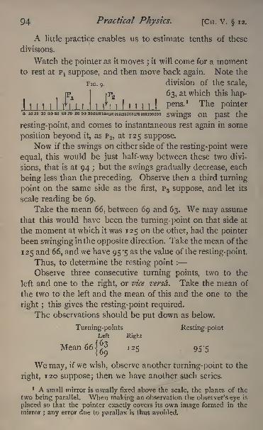
94 Practical Physics. [CH. V. 12.
A little practice enables us to estimate tenths of these
divisions.
Watch the pointer as it moves;it will come for a moment
to rest at P1 suppose, and then move back again. Note the
FIG. 9. division of the scale,
1 I M I n I I
63, at which this hap-
MM! I I M 1.1 P6115'
1 The P inter|
O 1020 30 3050 6070 80 90aOOJ10120130M01501G017<U80J90200 SWingS On
resting-point, and comes to instantaneous rest again in some
position beyond it, as P 2 ,at 125 suppose.
Now if the swings on either side of the resting-point were
equal, this would be just half-way between these two divi-
sions, that is at 94 ;but the swings gradually decrease, each
being less than the preceding. Observe then a third turning
point on the same side as the first, P3 suppose, and let its
scale reading be 69.
Take the mean 66, between 69 and 63. We may assume
that this would have been the turning-point on that side at
the moment at which it was 125 on the other, had the pointer
been swinging in the opposite direction. Take the mean of the
125 and 66, and we have 95 -5 as the value of the resting-point.
Thus, to determine the resting point :
Observe three consecutive turning points, two to the
left and one to the right, or vice versd. Take the mean of
the two to the left and the mean of this and the one to the
right ;this gives the resting-point required.
The observations should be put down as below.
Turning-points Resting-pointLeft Right
Mean66Jj?3 125 95-5
We may, if we wish, observe another turning-point to the
right, 120 suppose; then we have another such series.
1 A small mirror is usually fixed above the scale, the planes of the
two being parallel. When making an observation the observer's eye is
placed so that the pointer exactly covers its own image formed in the
mirror ; any error due to parallax is thus avoided.
CH. v. 12.] Measurement of Mass. 95
Proceeding thus we get a set of determinations of the
resting-point, the mean of which will give us the true
position with great accuracy.
Having thus found the resting point with the pans empty,turn the key or lever, and fix the beam ; then put the object to
be weighed in one scale pan. Suppose it to be the left-hand,
for clearness in the description. Then put on some weight,
50 grammes say, and just begin to turn the key to throw
the balance into action. Suppose the pointer moves sharply
to the left, 50 gms. is too much. Turn the key back, re-
move the 50 and put on 20; just begin to turn the key ;
the
pointer moves to the right, 20 is too little. Turn the key
back, and add 10;the pointer still moves to the right ;
add
10 more, it moves to the left ; 40 is too much. Turn the
key back, remove the 10 and add 5. Proceed in this way,
putting on the weights in the order in which they come, re-
moving each weight again if the pointer move sharply to
the left, that is, if it be obviously too much, or putting on an
additional weight if the pointer move to the rightThere is no necessity to turn the key to its full extent
to decide if a weight be too much or too little until we get
very nearly the right weight ;the first motion of the pointer
is sufficient to give the required indication.
It saves time in the long run to put on the weights in the
order in which they come in the box.
Caution. The beam must always be fixed before a
weight is changed.
Suppose now we find that with 37*68 grammes the pointermoves to the right, shewing the weight too little, and that with
37-69 the motion is to the left, shewing that it is too much.
Close the balance-case, leaving on the lighter weight, 37*68
grammes. Turn the key, and notice if the pointer will
swing off the scale or not. Suppose it is quite clear that
it will, or that the resting-point will be quite at one end near
the division 200. Fix the beam, and put on the rider say
g6 Practical Physics. [Cn. V. 12.
at division 2. This is equivalent to adding '002 gm. to the
weights in the scale pan, so that the weight there may nowbe reckoned as 37-682 gms. Release the beam, and let it
oscillate, and suppose that this time the pointer remains on
the scale.
Read three turning-points as before.
Turning-points Resting-pointLeft Right
Mean 1 701
'72gS I34
Thus we find that with no weights in the scale pans, the
resting-point is 95 -5 we may call this 96 with sufficient ac-
curacy while, with the object to be weighed in the left pan,and 37*682 grammes in the right, the resting-point is 134.
Hence 37*682 gms. is too small, and we require to find
what is the exact weight we must add to bring the resting-
point from 134 to 96, that is, through 38 divisions of the scale.
To effect this, move the rider through a ew divisions on
the beam, say through 5 ; that is, place it at division 7. Theeffective weight in the scale pan is now 37*687 gms.; observe
as before.
Turning-points Resting-point
Left Right
Mean 46|
4g
102 74
The addition of '005 gramme has moved the resting-
point from 134 to 74 ;that is, through 60 divisions.
We have then to determine by simple proportion what
weight we must add to the 37-682 in order to move the
resting-point through the 38 divisions;that is, from 134 to
96. The weight required is ff x '005 or -00316 gm. If then
we add -00316 gm. to the 37*682, the resting-point will be
96, the same as when the scale pans were empty.Thus the weight of the body is 37*68516 gms.We have not been working with sufficient accuracy to
make the last figure at all certain;we will therefore discard
it, and take the weight as 37*6852 grammes (p. 37).
CH. V. 12.] Measurement of Mass. 97
One or two other points require notice.
In each case we have supposed the pointer to swing over
from 60 to 70 divisions;this is as large a swing as should be
allowed.
We have supposed the resting point, when the balance
was unloaded, to lie between those for the two cases in which
the load was 37^682 and 37*687; the weights should alwaysbe adjusted so that the like may be the case.
We have supposed that the weight for which we first
observe the swing is too small. It is more convenient that
this should be so;
it is not absolutely necessary : we mighthave started from the heavier weight, and then moved the
rider so as to reduce the weight in the right-hand pan.We must be careful to make no mistake as to the weights
actually in the scale pan. It is generally wise for beginnersto add them up as they rest on the pan, putting down each
separately, grouping those weights together which belongto each separate digit, thus arranging them in groups of
grammes, decigrammes, centigrammes, and milligrammes,and then to check the result by means of the vacant places
left in the box.
When the weighing is completed see that the weights are
replaced in their proper positions in the box, and that the
beam is not left swinging.
We shall in future refer to this method of weighing as
the 'method of oscillations.'
The alteration produced in the position of the resting
point for a given small addition to the weights in the pan is
called, as we have seen, the sensitiveness of the balance for
that addition (p. 86).
Thus in our case the resting-point was altered by 60
for an addition of "005 gramme.The sensitiveness, then, is 60/5 or 12 per milligramme.
The load in the pans in this case was nearly 38 grammes.We should find by experiment that the sensitiveness
depends slightly on the load in the pans. (See p. 86.)
H
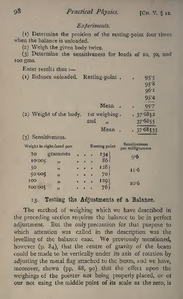
9$ Practical Physics. [CH. V. 12.
Experiments.
(1) Determine the position of the resting-point four times
when the balance is unloaded.
(2) Weigh the given body twice.
(3) Determine the sensitiveness for loads of 10, 50, andloo gms.
Enter results thus :
(1) Balance unloaded. Resting-point . . 95*5
95-8
96-1
95'4
Mean . . 957
(2) Weight of the body, ist weighing. .37-68522nd 37*6855
Mean . . 37-68535
(3) Sensitiveness.
Weight in right-hand pan Resting point
10 grammes . . . 134)fi
10-005 ... 86}
... "850-005 ... 70
... 129) I0 .6100-005 76]
13. Testing the Adjustments of a Balance.
The method of weighing which we have described in
the preceding section requires the balance to be in perfect
adjustment. But the only precaution for that purpose to
which attention was called in the description was the
levelling of the balance case. We previously mentioned,however (p. 84), that the centre of gravity of the beamcould be made to be vertically under its axis of rotation by
adjusting the metal flag attached to the beam, and we have,
moreover, shewn (pp. 88, 90) that the effect upon the
weighings of the pointer not being properly placed, or of
our not using the middle point of its scale as the zero, is
CH. V. 13.] Measurement of Mass. 99
inappreciable. We need consider, therefore, only the adjust-
ment to equality of the weights of the scale pans and of the
lengths of the arms. The former may, if necessary, be made
equal by filing one of them until the necessary equality is
attained, while the latter can be adjusted by means of the
screws which attach the end knife-edges to the beam.
We have, however, said nothing as yet about adjustingthe sensitiveness of the balance. A delicate balance is
generally provided with a small sphere fixed to the beam
vertically above the middle knife-edge, whose height can be
altered by means of the vertical screw passing through its
centre, by which it is supported. By raising or lowering this
sphere, called the inertia bob, we can diminish or increase
the value of h in equation (i) (p. 85), and thus increase or
diminish the sensitiveness of the balance. At the same
time the moment of inertia (see p. 144) of the beam about
the axis of rotation is correspondingly increased, and with
it the time of swing of the pointer. . Now a long period of
swing involves spending a long time over the weighings,
and this is a disadvantage ;it is therefore not advisable to
make the sensitiveness so great that the time of swing is
inconveniently long.
The usual period of swing is about 15 seconds. Lord
Rayleigh has, however, recently suggested (Brit. Assoc. 1883)
that the same accuracy of weighing with considerable saving
of time may be secured by loading the pointer of the balance
so that the time of swing is about 5 seconds, and using a
magnifying glass to read the turning points of the pointer,
and thus making up for the diminished sensitiveness byincreased accuracy of reading.
None of these adjustments should be carried out by any
but practised observers with the balance, and not by them
except after consultation with those who are responsible for
the safe custody of the instrument. It is, however, very
important for every observer to be able to tell whether or
not the balance is in adjustment, and we therefore proceedH 2
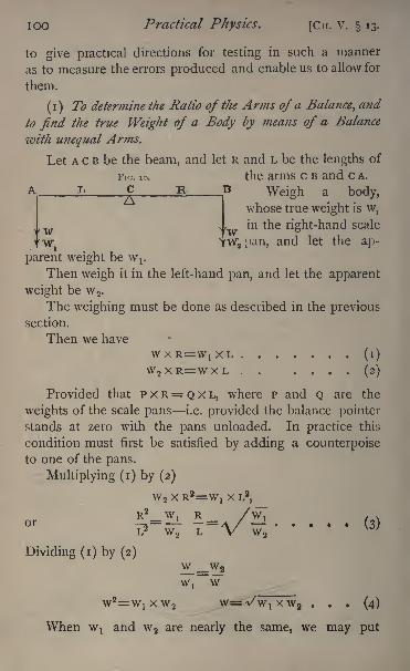
IOO Practical Physics. [Ctr. V. 13.
to give practical directions for testing in such a manner
as to measure the errors produced and enable us to allow for
them.
(i) To determine the Ratio of the Arms of a Balance^ and
to find the true Weight of a Body by means of a Balance
with unequal Arms.
Let A c B be the beam, and let R and L be the lengths of
Fin. 10. the arms c B and CA.
A i> C R. B Weigh a body,
whose true weight is w,
1 in the right-hand scale
YWipan, and let the ap-
parent weight be Wj.
Then weigh it in the left-hand pan, and let the apparent
weight be w2 .
The weighing must be done as described in the previoussection.
Then we have
WXR=WIXL ....... (i)
W 2 XR=WXL . . .... (2)
Provided that P x R= Q x L, where P and Q are the
weights of the scale pans i.e. provided the balance pointer
stands at zero with the pans unloaded. In practice this
condition must first be satisfied by adding a counterpoiseto one of the pans.
Multiplying (i) by (2)
Dividing (i) by (2)
w 2 x R2=W! x L2,
W__W 2
w2=w> x w 2w= -v/w, xw2 ... (4)
When Wj and w 2 are nearly the same, we may put
CH. v. 13.] Measurement of Mass. 101
for \/\v l\v 2 , )-{W|+ws)f
since the error depends on
{ <v/w"i \/w 2 )
2jand tru
'
y quantity is very small. (See p. 45).
Thus, if w,, w 2 be the apparent weights of w in the two
pans right and left respectively, the ratio of the arms is
the square root of the ratio of w}to w 2 . The true value of
w is the square root of the product w^ x w 2 .
Thus, if when weighed in the right pan, the apparent
weight of a body is 37*686 grammes, and when weighed in
the left, it is 37*592,
R / -2/7*68 "6-=*/< = 1-00125.
w= \/ 37-686 x 37'59 2 =37'635 grammes.
The true weight of a body may also be determined in a
badly adjusted balance by the following method, known as
the method of taring. Place the body in one scale pan and
counterpoise it, reading the position of equilibrium of the
pointer with as great accuracy as possible ; then, leaving the
same counterpoise, replace the body by standard weights,
until the position of equilibrium of the pointer is the sameas before. The mass which thus replaces the body is evi-
dently that of the body, no matter what state the balance
may be in. (This is called Borda's method.)
(2) To Compare the Weights of the Scale Pans.
Let a be the length of the arms supposed equal, s the
weight of one pan, and s + w that of the other.
Weigh a body whose weight is Q first in the pan whose
weight is s;
let the apparent weight be w.
Then interchange the scale pans and weigh Q again ; let
the weight be w'.
Then (s+ Q) a= (w+ s+ a>)a
Divide each by a, and subtract; then o>=w' w o>, or
w=i(w' w).
IO2 Practical Physics. [CH. V. 13.
Thus, weigh the body in one pan ;let its weight be w.
Interchange the scale pans and weigh the body again in the
other scale pan, but on the same side of the fulcrum;
let the
weight be w', then the difference in the weight of the scale
pans is \ (w' w).
This will be true very approximately, even if the arms
be not equal ;for let one be R and the other L. Then we
have
+ Q)R=(W/
H-S)L
<o=(w' wo>)
.
R
Now - is nearly unity ;we may put it equal to i+p,R
where p is very small.
u)=(w'-w-o>) (i+p)w' w <D +p (w'
- w w).
But we suppose that w, and therefore w' w, is verysmall. Thus p(w
/ w w), being the product of two small
quantities, may be neglected, and we get
o>=w' w w or
Experiments.
(1) Determine the ratio of the arms of the given balance.
(2) Determine the difference between the weights of the
scale pans.Enter as below :
(1) Weight in right-hand pan = 37-686 gms.left-hand pan = 37-592
^ = 1-00125LJ
w = 37-650
(2) Weight in left-hand pan = 37 '592
pans interchanged = 37'5 83 >
.'. Left-hand pan right-hand pan = '0045 &m -
CH. V. 14.] Measurement of Mass. 103
14. Correction of Weighings for the Buoyancy of the Air.
The object of weighing a body is to determine its mass,
and the physical law upon which the measurement dependsis that the weights of bodies are proportional to their masses,if they are sufficiently near together.
Now we have all along assumed that when an adjustedbalance-beam was in equilibrium, the force of gravity uponthe weights was equal to the force of gravity upon the body
weighed, i.e. that their weights were equal, and this would
have been so if we had only to deal with the force of gra-
vity upon these bodies. But the bodies in question were sur-
rounded by air, and there was accordingly a force upon each
acting vertically upwards, due to the buoyancy of the air;
and it is the resultant force upon the weights which is equal
to the resultant force upon the body weighed. But the
forces being vertical in each case, their resultant is equal to
their difference ;and the force due to the displacement of
air by the body is equal to the weight of the air displaced,
i.e. it bears the same ratio to the weight of the body as
the specific gravity of air does to the specific gravity of
the body ;while the same holds for the weights.
Thus, if w be the weight of the body, a- its specific gravity,
and A the 'specific gravity of air at the pressure and tempera-
ture of the balance-case, the volume of air displaced is w/<r
and its weight wX/o- (p. 105). Hence the resultant force on
the body is wfi-")
; similarly, if o> be the weights, and
p their density, the force on the weights is o/iJ.
These two are equal, thus
w= = o>
(i - -+
)approximately,
since in general-
is very small...
104 Practical Physics. [CH. V. 14.
The magnitude of the correction for weighing in air
depends therefore upon the specific gravities of the weights,
the body weighed, and the density of the air at the time of
weighing, denoted by p, a-, and X respectively. The values
of p and a- may be taken from the tables of specific gravities
(tables, 17, 80) if the materials of which the bodies are com-
posed are known. If they are not known, we must determine
approximately the specific gravity. We may as a rule neglect
the effect of the buoyancy of the air upon the platinumand aluminium weights, and write for p, 8-4, the specific
gravity of brass, the larger weights being made of brass.
The value of X depends upon the pressure and temperatureof the air, and upon the amount of moisture which it con-
tains, but as the whole correction is small, we may take the
specific gravity of air at 15 C. and 760 mm., when half-
saturated with moisture, as a sufficiently accurate value of X.
This would give X=*ooi2.
Cases may, however, arise in which the variation of the
density of the air cannot be neglected. We will give one
instance. Suppose that we are determining the weight of a
small quantity of mercury, say 3 grammes, in a glass vessel
of considerable magnitude, weighing, say, 100 grammes.
Suppose that we weigh the empty vessel when the air is at
10 C. and 760 mm., and that we weigh it with the mercuryin at 15 C. and 720 mm. deducing the weight of the mercury
by subtracting the former weight from the latter. We mayneglect the effect of the air upon the weight of the mercury
itself, but we can easily see that the correction for weighingthe glass in air has changed in the interval between the
weighings from 22 mgm. to 20*5 mgm. The difference
between these, 1-5 mgm., will appear as an error in the
calculated weight of the mercury, if we neglect the variation
in density of the air, and this error is too considerable
a fraction of the weight of the mercury to be thus neg-
lected.
CH. V.] Measurement of Mass. 105
Experiment.
Determine the weight in vacuo of the given piece of platinum.
Enter results thus :
Weight in air at I5C. and 760 mm. with brass weights
37-634 gm. Specific gravity of platinum 21-5. Weight in
vacuo, 37-632.
DENSITIES AND SPECIFIC GRAVITIES.
DEFINITION i. The density of a substance at any tem-
perature is the mass of a unit of volume of the substance at
that temperature ;thus the density of water at 4 C. is one
gramme per cubic centimetre.
DEFINITION 2. The specific gravity of a substance at
any temperature is the ratio of its density at that tempera-ture to the density of some standard substance, generally the
maximum density of water (i.e. the density of water at 4 C.).
DEFINITION 3. The specific gravity of a body is the
ratio of the mass of the body to the mass of an equal volume
of some standard substance, generally water at 4 C.
It evidently follows from these definitions that, if p be
the density of a substance, <r its specific gravity, and o> the
maximum density of water, p=o-co, and if M be the mass of
a body consisting of the substance, whose volume is v, then
M=vp=vo-a>, and the mass of a volume of water equal to
1 It is unfortunate that in many physical text-books the terms'
density' and '
specific gravity'
are used synonymously, the former
being generally employed for gases and liquids, the latter for solids.
It is quite evident that there are two very distinct ideas to be repre-
sented, namely (i) the mass of the unit of volume, a quantity whosenumerical value depends of course on the units chosen for measuringmasses and volumes ; and (2) the ratio of the mass of any volume to
the mass of an equal volume of water at 4 C. ; this quantity being a
ratio, is altogether independent of units. There being now also two
names,'
density' and '
specific gravity', it seems reasonable to assignthe one name to the one idea and the other name to the other idea,as suggested by Maxwell,
'
Theory of Heat '
(ed. 1872, p. 82).
When there is no danger of confusion arising from using the term
density when specific gravity is meant, there may be no harm in doingso, but beginners should be careful to use the two words strictly
in the senses here defined.
io6 Practical Physics. [CH. V. 14.
the volun e of the body= v <o. The maximum density of
water is i gramme per cubic centimetre. If we use the
gramme as the unit of mass, and the cubic centimetre as the
unit of volume, the numerical value of w is unity and the
equations we have written become p=<r and M=VO-. Thus,the numerical value of the density of a substance on the
C.G.S. system of units is the same as the number which
expresses the specific gravity of the substance, this latter
being of course a ratio, and therefore independent of units.
And for the C.G.S. system of units, moreover, the numerical
value of the mass of a body is equal to the number which
expresses its volume multiplied by its specific gravity.
These relations are only true for the C.G.S. system, and
any other systems in which the unit of mass is the mass of
the unit of volume of water at 4 C. ;but whatever be the
system, the density of water at 4 C. is accurately known,
although its numerical value may not be unity. Hence, in
order to calculate the volume of a body whose mass is known,or vice versa, we require only to know its specific gravity,
and hence the practical importance of determinations of
specific gravity. It is generally an easy matter to determine
experimentally the ratio of the mass of a body to the mass
of an equal volume of water at the same temperature, but it
would not be easy or convenient always to keep the water at
its temperature of maximum density, throughout the experi-
ment. The densities of bodies are therefore not usually
experimentally compared directly with the maximum density
of water in determining specific gravities, and the necessity
for doing so is obviated by our knowing with great accu-
racy the density of water at different temperatures, (this is
given in table 32) ;so that we are enabled, when we know .
the mass of a volume of water at any temperature, to
calculate from the table the mass of the same volume at
4 C., and thus obtain the specific gravity required. Weproceed to describe some of the practical methods in
general use.
CH. V. 15.] Measurement of Mass. 107
15. The Hydrostatic Balance.
The specific gravity of a substance is determined by the
hydrostatic balance by weighing the substance in air, and
also in water.
One scale pan is removed from the balance, and replaced
by a pan suspended by shorter strings from the beam. This
pan has a hook underneath, and from the hook the sub-
stance to be weighed is suspended by a piece of very fine
wire.
(i) To determine the Specific Gravity of a Solid heavier
than Water.
We must first make sure that the beam is horizontal whenthe balance is loaded only with the wire which is to carry
the substance.
Turn the key or lever gently to release the beam ; the
pointer will probably move sharply across the scale, showingthat one pan is heavier than the other.
Fix the beam again, and put shot or pieces of tinfoil into
the lighter scale until it becomes nearly equal in weight to
the other, then let it swing, and observe a resting-point as in
12. The weights put in should be so adjusted that this
resting-point may be near the centre of the scale.
Do not counterpoise with weights which you may subse-
quently require in order to weigh the object.
Hang the object whose specific gravity you require a
piece of copper suppose by the fine wire from the hook
above mentioned, and weigh it twice or three times by the
method of oscillations ( 12). Let its weight be 11*378
grammes.Fill a vessel with distilled water, and bring it under the
end of the beam so that the copper may dip completely into
the water.
Be careful that no air-bubbles adhere to the copper; if
there be any, remove them by means of a small brush or
feather, or a fibre of glass. It is well to use water that has
loS Practical Physics. [CH. V. 15.
been freed from dissolved air either by boiling or by means
of an air-pump. Any very small bubbles not easily re-
movable by mechanical means will then be dissolved by the
water.
Be careful also that the wire which supports the coppercuts the surface of the water only once
;there is always a
certain amount of sticking, due to surface tension between
the wire and the surface of the water, and this is increased
if a loose end of the wire be left which rises through the
surface. To completely avoid the effect of surface tension
the diameter of wire should not be greater than -004 inch.
Weigh the copper in the water;
it will probably be found
that the pointer will not oscillate, but will come to rest almost
immediately. Observe the resting-point, and by turning the
key set the beam swinging again, and take another observa-
tion. Do this four times, and take the mean.
Add some small weight, say '01 gramme, to the weight,
and observe another resting-point, and from these observa-
tions calculate, as in 12, the weight of the copper in water;
it will be about IOTOI grammes. Observe at the same
time the temperature of the water with a thermometer.
Suppose it is 15.Then it follows that the weight of the water displaced is
11-378 lo-ioi grammes, or 1*277 gramme.Now the specific gravity of a substance is equal to
weight of substance
weight of equal vol. water at 4C.'
In all cases, if we know the weight of a volume of water
at /, we can find its weight at 4 C., by dividing the weight
at i by the specific gravity of water at /.
Thus, weight at 4 = ^ightat /
specific gravity at t
The specific gravity of water at f may be taken from
table (32).
CH. V. 15.] Measurement of Mass. 109
In this case, the weight of the equal volume of water at
15 C. is 1*277 gramme, and the specific gravity of water at
5 is -99917.
.'. The weight of the equal volume of water at 4 C
=_L77 =I . 8 .
99917
Thus, the specific gravity of copper
=1^=8-903.1-278
It is well to pour the water into the beaker or vessel
that is to hold it, before beginning the experiment, and leave
it near the balance, so that it may acquire the temperatureof the room.
If greater accuracy be required, we must free the water
used from air. This can be done by putting it under the
receiver of an air-pump and exhausting, or by boiling the
water for some time and then allowing it to cool.
We have neglected the effect of the wire which is im-
mersed in the water ; we can, if we need, correct for this.
We have also neglected the correction to the observed
weight, which arises from the fact that the weights used
displace some air, so that the observed weight in air is
really the true weight minus the weight of air displaced.
(2) To determine the Specific Gravity of a Solid lighter
than Water.
If we wish to find the specific gravity of a solid lighter
than water, we must first weigh the light solid in air, then
tie it on to a heavier solid, called a sinker, whose weightand specific gravity we know. The combination should be
such that the whole will sink in water.
Let w and a- be the weight in air, and the specific gravity
of the light solid a piece of wax, for instance w', a-' corre-
sponding quantities for the sinker, w, tr for the combina-
HO Practical Physics. [CH. V. 15.
tion; /, w the weights in water of the sinker and the
combination respectively.
Then, using C.G.S. units, w/<r represents the volume of
the wax, w'/o-' that of the sinker, w/o- that of the combina-
tion.
Since the volume of the wax is equal to that of the
combination minus that of the sinker, we get
w w w'
But, with the_proper temperature corrections,
w__ _Or
and
w'
*. =w w (w' w'\
or remembering that w=w+w'
w<r= =
,.w w+ w'
w, w\ w can each be observed, and thus the specific gravity
of the wax determined.
If it is convenient to tie the sinker so that it is immersed
while the solid itself is out of the water, the following method
is still simpler.
Weigh the solid in air and let its weight be w.
Attach the sinker below the solid, and weigh the com-
bination with the former only immersed. Let the weightbe w
t.
Raise the vessel containing the water so that the solid
is immersed as well as the sinker, and let the weight be w 2.
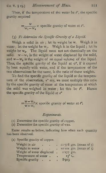
CH. V. 15.]Measurement of Mass. 1 1 1
Then, if the temperature of the water be ^, the specific
gravity required
= x specific gravity of water at t.
(3) To determine the Specific Gravity of a Liquid.
Weigh a solid in air;
let its weight be w. Weigh jt in
water; let the weight be w,. Weigh it in the liquid ;let its
weight be w 2 . The liquid must not act chemically on the
solid, w Wj is the weight of water displaced by the solid,
and w w2 is the weight of an equal volume of the liquid.
Thus, the specific gravity of the liquid at o, if it expand
by heat equally with water, and if the temperature of the
two observations be the same, is the ratio of these weights.
To find the specific gravity of the liquid at the tempera-ture of the observation, T say, we must multiply this ratio
by the specific gravity of water at the temperature at which
the solid was weighed in water ; let this be /. Hencethe specific gravity of the liquid at T
wat
Experiments.
(1) Determine the specific gravity of copper.
(2) Determine the specific gravity of wax.
Enter results as below, indicating how often each quantityhas been observed.
(i) Specific gravity of copper.
Weight in air . . . 11*378 gm. (mean of 3)
Weight in water . . . icrioi gm. (mean of 3)
Weight of water displaced . 1-277 gm.Temperature of water . . 15 C.
Specific gravity . . . 8-903
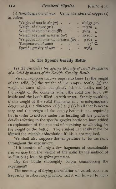
112 Practical Physics. [CH. V. 15.
(2) Specific gravity of wax. Using the piece of copper (i)
as sinker.
Weight of wax in air (w) . . .26-653 gm -
Weight of sinker (w') . . . . 11-378
Weight of combination (w) . . 38-031
Weight of sinker in water (/') . . 10-101
Weight of combination in water (w) . 9*163
Temperature of water . . . 1 5 C.
Specific gravity of wax . . . 0-965
1 6. The Specific Gravity Bottle.
(i) To determine the Specific Gravity of small Fragments
of a Solid by means of the Specific Gravity Bottle.
We shall suppose that we require to know (i) the weightof the solid, (2) the weight of the empty bottle, (3) the
weight of water which completely fills the bottle, and (4)
the weight of the contents when the solid has been put
inside and the bottle filled up with water. Strictly speaking,
if the weight of the solid fragments can be independently
determined, the difference of (4) and (3) is all that is neces-
sary, and the weight of the empty bottle is not required ;
but in order to include under one heading all the practical
details referring to the specific gravity bottle we have added
an explanation of the method of obtaining or allowing for
the weight of the bottle. The student can easily make for
himself the suitable abbreviation if this is not required.
We shall also suppose the temperature to be the same
throughout the experiment.If it consists of only a few fragments of considerable
size we may find the weight of the solid by the method of
oscillations; let it be 5*672 grammes.
Dry the bottle thoroughly before commencing the
experiment.The necessity of drying the - interior of vessels occurs so
frequently in laboratory practice, that it will be well to men-
CH. v. 16.] Measurement of Mass. 113
tion here the different methods which are suitable under
different circumstances in order that we may be able to
refer to them afterwards. We may take for granted that all
the water that can be removed by shaking or by soaking upwith slips of filter paper, has been so got rid of.
An ordinary bottle or flask can for most purposes be suf-
ficiently dried by drawing air through it by means of a tube
passing to the bottom of the bottle and connected with an
aspirator or the aspirating pump referred to in the note (p. 75),
and at the same time gently warming the bottle by means of
a spirit lamp. If there be any considerable quantity of water
to be got rid of, the process can be considerably shortened
by first rinsing out the bottle with alcohol. If more careful
drying is necessary, as, for instance, for hygrometric ex-
periments, the mouth of the vessel should be closed by a
cork perforated for two tubes, the one opening at one end
and the other at the other end of the vessel, and a current of
perfectly dry air kept passing through the vessel for some
hours. The air may be dried by causing it to pass first
through U-tubes filled with fused chloride of calcium, which
will remove the greater part of the moisture, and finally
thorough a tube containing phosphoric anhydride or frag-
ments of ignited pumice moistened with the strongest
sulphuric acid.
If there be no opening in the vessel sufficiently large
to allow of two tubes passing, the following plan may be
adopted : Connect the tube which forms the prolongationof the plug of a three-way tap
1 with an air-pump. Thewater air-pump before referred to is very convenient for the
purpose if there be a sufficient head of water on the water-
1 A three-way tap is a simple, but in many ways very useful, con-
trivance. In addition to the two openings of an ordinary tap, it has a
third, formed by a tubular elongation of the plug, and communicatingwith that part of the conical face of the plug which is on the same cross-
section as the usual holes, but at one end of a diameter perpendicular to
the line joining them. Such taps may now be obtained from many of
the glass-blowers.
1
114 Practical Physics. [CH. V. 16.
supply to give efficient exhaustion. Connect the other
openings of the tap with the vessel to be dried and the dry-
ing tubes respectively. Then, by turning the tap, connection
can be made alternately between the pump and the vessel
and between the vessel and the drying tubes, so that the
vessel can be alternately exhausted and filled with dried
air. This process must be repeated very many times if the
vessel is to be completely dried.
Having by one of these methods thoroughly dried the
bottle, place it on one of the scale pans of the balance,
and counterpoise on the other either with the brass weight
provided for the purpose, or by means of shot or pieces
of lead. Observe the resting-point of the pointer by the
method of oscillations, taking two or three observations.
Meanwhile a beaker of distilled water, which has been
freed from air either by boiling or by being enclosed in the
exhausted receiver of an air-pump, should have been placednear the balance, with a thermometer in it, in order that the
water used may have had time to acquire the temperatureof the room and that the temperature may be observed.
Fill the bottle with the water, taking care that no air-
bubbles are left in. To do this the bottle is filled up to the
brim, and the stopper well wetted with water. The end of
the stopper is then brought into contact with the surface of
the water, taking care that no air is enclosed between, and
the stopper pushed home.
All traces of moisture must be carefully removed from
the outside of the bottle by wiping it with a dry cloth.
Observe the temperature of the water before inserting
the stopper ;let it be 15 C. The bottle should be handled
as little as possible, to avoid altering its temperature.
Replace the bottle on the scale pan, and weigh ;let the
weight observed be 24-975 grammes.This weighing, like every other, should be done twice or
three times, and the mean taken.
This is the weight of the water in the bottle only, for we
CH. V. 16.] Measurement of Mass. 115
have supposed that the bottle has been previously counter-
poised.
Open the bottle and introduce the small fragments of
the solid which have been weighed, taking care to put all in.
Again fill the bottle, making sure by careful shaking that
no air-bubbles are held down by the pieces of the solid ;if
any are observed, they must be removed by shaking or by
stirring with a clean glass rod; or, if great accuracy is re-
quired, by placing the bottle under the receiver of an air-
pump and then exhausting.
Replace the stopper, carefully wiping off all moisture,
and weigh again, twice or three times;
let the weight be
27764 grammes.This is clearly the weight of the substance + the weight
of the bottleful of water - the weight of water displaced bythe substance.
Thus the weight of water displaced is equal to the weightof the substance + the weight of the bottleful of water
27764 grammes
= 30-647 27764=2 883 grammes.
Now we require the weight of water which would be
displaced were the temperature 4C. ;for the specific gravity
of a substance is equal to
weight of substance
weight of equal vol. water at 4
but the weight of any volume of water at 4
_ weight of equal vol. at t
specific gravity water at t
Thus the specific gravity of the substance
= weight of substancey wat ^ f
weight of equal vol. water at /
I 2
1 16 Practical Physics. [CH. V. 16.
Taking from the table (32) the specific gravity of water
at 15, we find the specific gravity of the substance to be
-x -9991 7= i -966.
If greater accuracy be required, we must free the water
used from air by boiling or the use of the air-pump. Weshould also require to correct the weighings for the air
displaced.
(2) To find the Specific Gravity of a Powder.
The process of finding the specific gravity of a powderis nearly identical with the foregoing. The only modifica-
tion necessary is to weigh the powder in the bottle. The
order of operations would then be
(1) Counterpoise the dry bottle.
(2) Introduce a convenient amount of the powder, say
enough to fill one third of the bottle, and weigh.
(3) Fill up with water, taking care that none of the
powder is floated away, and that there are no air-bubbles,
and weigh again. If it be impossible to make all the powder
sink, that which floats should be collected on a watch-glass,
dried, and weighed, and its weight allowed for.
(4) Empty the bottle, and then fill up with water and
weigh again.
The method of calculation is the same as before.
(3) To determine the Specific Gravity of a Liquid by the
Specific Gravity Bottle.
Fill the bottle with water, as described above, and weigh
the water contained, then fill with the liquid required, and
weigh again. Each weight should of course be taken twice.
The ratio of the two weights is the specific gravity of the
liquid at 4 C. if it expand by heat equally with water.
If we require the specific gravity of the liquid at the
temperature of the experiment, we must note the tempera-
ture of the water, and reduce its weight to the weight of an
CH. V. 16.] Measurement of Mass. 117
equal volume at 4 C. ; that is, we must multiply the above
ratio by the specific gravity of water at the temperature of
the observation.
Thus, the specific gravity of a liquid
= weight of liquid x waterweight of equal vol. water at /
Experiments.
(1) Determine the specific gravity of the given solid.
(2) Determine the specific gravity of the given liquid.
Enter as below, indicating the number of observations n adeof each quantity :
(1) Specific gravity of solid.
Weight of solid .... 5-672 gm. (3)
Weight of water in bottle . . 24-975 gm. (2)
Weight of water with solid . . 27764 gm. (3)
Temperature, 15 C.
Specific gravity, i -966.
(2) Specific gravity of liquid.
Weight of water in bottle . . . 24-975 gm.Weight of liquid 23-586 gm.Temperature . . . 15 C.
Specific gravity of liquid . . . '9430.
17. Nicholson's Hydrometer.
This instrument is used (i) to determine the specific
gravity of small solids which can be immersed in water;
(2) to determine the specific gravity of a liquid.
(i) Tofind the Specific Gravity ofa Solid.
Taking care that no air-bubbles adhere to it, place the
hydrometer in a tall vessel of distilled water recently boiled,
and put weights on the upper cup until it just sinks to the
mark on the stem.
To avoid the inconvenience caused by the weights falling
into the water, a circular plate of glass is provided as a cover
n8 Practical Physics. [CH. V. 17.
for the vessel in which the hydrometer floats. This has been
cut into two across a diameter, and a hole drilled throughthe centre, through which the stem of the instrument rises.
It will generally be found that with given weights on
the cup the hydrometer will rest in any position between
certain limits;
that there is no one definite position of
flotation, but many. The limits will be closer together and
the experiment more accurate if the surface of the instru-
ment, especially that of the stem, be thoroughly clean and
free from grease. It is well therefore carefully to rub the
stem and upper part of the bulb with some cotton-wool
soaked in methylated spirit.
Suppose now it is floating with the mark on the stem
just below the surface. Take off some weights until the
mark just rises past the surface ; let the weights then on be
8 -34 grammes. Put on weights until the mark just sinks
below the surface, and then let the weight be 8'3'5 grammes.Do this several times, and take the mean as the weight re-
quired to sink the markup the surface.
Let the mean be 8*345 grammes.Remove the weights and put the solid in the upper cup.
Then add weights until the mark again just comes to the
surface, estimating the weight required as before. Let this
be 2 '539 grammes. The weight of the solid in air is the
difference between these, or 5 '806 grammes.Now put the solid in the lower cup
1 and weights in the
upper one until the mark sinks to the surface. Estimate this
as before. Let the mean of the weights be $'462 grammes.The difference between this and the weight 8-345, put on
originally to sink the hydrometer, gives the weight in water.
Thus, the. weight in water = 2*883 grammes.And the weight of water displaced = weight in air
weight in water = 2-923 grammes.
1 If the solid he lighter than^water it must be fastened down to the
cup either by a wire or by being enclosed in a cage fixed to the instru-
ment.
CH.V. 17.]Measurement of Mass. 119
The specific gravity, therefore, referred to water at the
temperature of experiment
= 5*_62-923
To determine the true specific gravity water at 4 C.
being taken as the standard we must multiply this number
by the specific gravity of the water at the time of the ex-
periment.
This may be taken from the table (32), if we know the
temperature. Thus, we must observe the temperature of
the water at the time of the experiment. Let it be 15.Then the specific gravity required
= 1*987 x '999 j 7= 1*985 approximately.
(2) To determine the Specific Gravity ofa Liquid.
Let the weight of the instrument itself be 11-265
grammes. This must be determined by weighing it in a
balance.
Place it in the water, and put weights on the upper panuntil it just floats up to the mark on the stem. Let the
weight be 8-345 grammes. This of course must be estimated
as in experiment (i).
The sum of these two weights is the weight of a volume
of water equal to that of the instrument up to the mark on
the stem. Thus, the weight of this volume of water is 19*610
grammes.Now place the instrument in the liquid and add weights
till the mark is just in the surface. Let the weight be
9-875 grammes.Then the weight of the volume of liquid displaced is
11*265 + 9'8?5 or 21*140 grammes.
The specific gravity of the liquid referred to water at the
temperature of the experiment is therefore
2J24219-610
I2O Practical Physics. [Cn. v. 17.
Let the temperature of the water be i5C. ;that of the
liquid n*5G Then the specific gravity of liquid at
1 1-5 C. is
Experiments.
(1) Determine the specific gravity of sulphur by Nicholson's
Hydrometer.
(2) Make a 20 per cent, solution 1 of common salt in water,
and determine its specific gravity by Nicholson's Hydrometer.
Enter results thus :
(a) Specific gravity of sulphur.Mean weight required to sink the hydrometer
to the mark 8*345 gms.Mean weight required to sink the hydrometer
with sulphur on upper pan.... 2*539Mean weight required to sink the hydrometer
with sulphur on lower pan .... 5*462
Temperature of the water, 1 5 C.
Sp. gr. of sulphur = 1*985.
(b] Specific gravity of salt solution.
Weight of salt used 539'O g^s.
Weight of water used 2156*0
Weight of hydrometer . . . . .11 -265
Weight required to sink the instrument to the
mark in water at 1 5 8-345
Weight required to sink instrument in solution
at ii-sC 9-875
Specific gravity of solution .... 1-077
1 8. Jolly's Balance.
The apparatus consists of a long spiral spring carrying a
pan into which weights or the object to be weighed can be
put.
1 A 20 per cent, solution is one which contains 20 parts by weightof salt in 100 parts of the solution. It may therefore be made byadding the salt to water in the proportion of 20 grammes of salt to 80
grammes of water.
CH. V. 1 8.] Measurement of Mass. 12 1
From this there hangs, by a fine thread, a second panwhich is always kept immersed in water.
Behind the spring is a millimetre scale engraved on a
strip of looking-glass, and just above the pan is a white bead,
which can be seen directly reflected in the glass.
By placing the eye so that the top of the bead just
appears to coincide with its own image, the division of the
scale which is opposite to the top of the bead can be- read
with great accuracy.
(i) To weigh a small Body andfind its Specific Gravity.
Place the object to be weighed in the upper pan, taking
care that the lower pan is well below the surface of the
water, and that the vessel in which the water is, is suffi-
ciently large to allow the pan to hang clear of the sides.
Note the division of the scale which coincides with the
top of the bead. Suppose it is 329.
Remove the object from the pan and replace it by
weights until the bead occupies the same position as before.
Let the weights be 7*963 grammes.It may be impossible with given weights to cause the
bead to come to exactly the same position.
Thus, we may find that 7*963 gms. causes it to stand at
330, while ^7*964 gms. brings it to 327*5. The true weightlies between these two
;and the addition of *ooi gramme
lowers the bead through 2*5 mm. We require the bead to
be lowered from 330 to 329 that is, through i mm. Wemust therefore add to our weight
of *ooi gramme, or 0*0004 gramme.2 '5
The true weight then would be 7*9634 grammes.The water should be adjusted so that its surface is
above the point of junction of the three wires which carry
the lower pan.
Next place the small object in the lower pan, and put
weights into the upper till the bead again comes to the
122 Practical Physics. [CH. V. 18.
same point on the scale. Let the weights be 3 -9 782
grammes.This is clearly the weight of the water displaced by the
object, and its specific gravity referred to water at the tem-
perature of the observation is therefore
'"
3.4 or 2'oo2.
3-9782
To obtain the true specific gravity, we must multiply
this by the specific gravity of the water at the temperatureof the observation. Let this be 15.
The specific gravity of water at 15 is '99917, so that
the specific gravity of the solid is
2'OO2 X '99917, Or 2'OOO.
(2) To determine the Specific Gravity of a Liquid.
Take a small solid which will not be acted on by the
liquid, and place it in the upper pan. Note the point to
which the bead is depressed, the lower pan being in water.
Now place the solid in the lower pan and put weights
into the upper until the bead comes opposite the same
mark. Let the weight be 3*596 grammes. This is the
weight of the water displaced by the solid.
Remove the water and replace it by the liquid. Put
the solid into the upper pan, and note the division opposite
to which the bead stands. Let it be 263.
Put the solid into the lower pan, and put weights into
the upper until the bead comes opposite to 263. Let the
weight be 4732 grammes. This is the weight of the liquid
displaced by the solid.
Thus, the specific gravity of the liquid
= 473*X
.
3I6 .
3-596
This must be corrected for temperature as usual.
CH. V. 18.]Measurement of Mass. 123
Experiments.
(1) Determine by means of Jolly's Balance the specific
gravity of the given small crystal.
(2) Determine by means of Jolly's Balance the specific
gravity of the given liquid.
Enter the results thus :
(1) Specific gravity of crystal.
Scale reading with the crystal in the upper
pan 329 mm.
Weight required to bring the bead to same
position , 7*9634 gms.
Weight required with crystal in lower pan . 3*9782
Temperature of water 1 5 C.
Sp. gr. of crystal 2-000.
(2) Specific gravity of liquid.
Scale reading with solid in upper pan, lower
pan in water 329 mm.
Weight required to bring the bead to the same
reading with the solid in water. . . 3*596 gms.Scale reading with the solid in the upper pan,
lower pan in the liquid .... 263 mm.
Weight required to bring the bead to the same
reading with the solid in the liquid . . 4*732 gms.
Temperature of the water 15 C.
Specific gravity of liquid=
1-315.
19. The Common Hydrometer.
The specific gravity of a liquid may be most easily
determined to within 0*1 percent, by the use of the common
hydrometer.This instrument consists of a glass bulb with a cylin-
drical stem, loaded so that it floats in any liquid whose
specific gravity lies within certain limits, with the stem
vertical and partly immersed. The depth to which it
requires to be immersed in order to float is defined by the
condition that the weight of the liquid displaced is equal to
the weight of the hydrometer. For any liquid, therefore,
124 Practical Physics. [CH. V. 19.
within the limits, there is a definite point on the stem to
which the instrument will sink, depending on the specific
gravity ;and the stem can be graduated in such a manner
that the graduation reading gives the specific gravity at
once. This is generally done by a scale attached to the
inside of the stem, and hence all that has to be done to
determine the specific gravity of a liquid is to float in it a
suitable hydrometer, and take the scale reading at the sur-
face. The temperature correction is to be allowed for as
usual.
An instrument sensitive to such slight variations of
density as o't per cent, would require to have too long a
stem if used for the whole range of density commonlyoccurring. Hydrometers are, therefore, usually obtained in
sets of three or four, each suitable for one portion only of
the range. The case in which they are kept contains a long
cylindrical vessel, which is convenient for floating them in
and also a thermometer.
The hydrometers, vessel, and thermometer should be
carefully washed and dried before replacing them in the
case.
The graduation of the scale is a comparatively difficult
matter, as equal increments in the length of the stem
immersed do not correspond to equal differences of density.
The scales are graduated by the instrument-makers, and we
require to be able to test the accuracy of the graduation.
We can do this by taking the hydrometer readings in
liquids whose specific gravities are known. Distilled water
would naturally be a suitable one for the purpose. The
hydrometer when floating in distilled water at 15 C/ should
read 0-999. The specific gravity of any other suitable liquid
could be determined by one of the methods already de-
scribed. The following experiment, however, serves as a
very instructive method of comparing the density of any
liquid with that of water, and it is, therefore, suggested as a
means of testing the accuracy of the hydrometer scale.
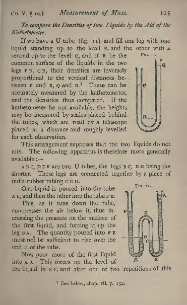
Cn. V. 19.] Measurement of Mass. 12$
FIG. ii.
To compare the Densities of two Liquids by the Aid of the
Kathetometer.
If we have a U tube (fig. n) and fill one leg with one
liquid standing up to the level p, and the other with a
second up to the level Q, and if R be the
common surface of the liquids in the two
legs PR, Q R, their densities are inversely
proportional to the vertical distances be-
tween P and R, Q and R. 1 These can be
accurately measured by the kathetometer,
and the densities thus compared. If the
kathetometer be not available, the heights
may be measured by scales placed behind
the tubes, which are read by a telescope
placed at a distance and roughly levelled
for each observation.
This arrangement supposes that the two liquids do not
mix. The following apparatus is therefore more generally
available :
ABC, D E F are two U tubes, the legs B c, D E being the
shorter. These legs are connected together by a piece of
india-rubber tubing c G D.
One liquid is poured into the tube
A B, and then the other into the tube F E.
This, as it runs down the tube,
compresses the air below it, thus in-
creasing the pressure on the surface of
the first liquid, and forcing it up the
leg B A. The quantity poured into F E
must ridl be sufficient to rise over the
end D of the tube.
Now pour more of the first liquid
into A R. This forces up the level of
the liquid in E F, and after one or two repetitions of this
FIG. 12.
1 See below, chap. vii. p. 152.
126 Practical Physics. [Ci-i. V. 19.
operation the levels of the liquid in one tube will be at A
and c, those in the other being at F and D.
The pressure at c and D, being thai of the enclosed air,
is the same.
The excess of the pressure at c above the atmospheric
pressure is due to a column of liquid of height equal to the
vertical distance between A and c, that at D is due to a columnof the second liquid of height equal to the distance betweenF and D.
These distances can be observed by the kathetometer, .
and the densities of the two liquids are inversely propor-tional to them.
The surface of the liquids in the tubes will be curved,
owing to capillary action. In measuring, either the bottom
or the top of the meniscus, whichever be most convenient,
may be observed, but it is necessary to take the same at
each end of the column. The bottom will, if the liquid
wet the tube, give the more accurate result.
It is well to hang up behind the tubes a sheet of white
or grey paper, to afford a good background against which to
see the liquids.
It is important that the temperature should remain the
same during the experiment ; for if it increase the pressure
in the portion c G D increases, and the air there expands,thus forcing up the columns of liquid. We may avoid the
difficulty this causes by the following method of taking the
measurements :
Observe the height of A, then the height of c, and finally
the height of A again.
Then, if the temperature has changed uniformly and the
intervals be .ween the successive measurements have been the
same, the mean of the two observed heights of A will give
its height at the time when the observation of the height of
c was made, and the difference between these two, the mean
of the observed heights of A and the height of c, will give
the true height of the column.
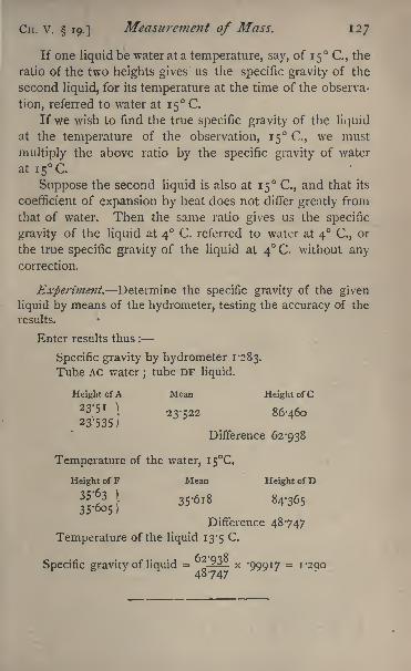
CH. V. 19.]Measurement of Mass. 127
If one liquid be water at a temperature, say, of 15 C., the
ratio of the two heights gives us the specific gravity of the
second liquid, for its temperature at the time of the observa-
tion, referred to water at 15 C.
If we wish to find the true specific gravity of the liquid
at the temperature of the observation, 15 C., we must
multiply the above ratio by the specific gravity of water
ati5 CSuppose the second liquid is also at 15 C., and that its
coefficient of expansion by heat does not differ greatly from
that of water. Then the same ratio gives us the specific
gravity of the liquid at 4 C. referred to water at 4 C., or
the true specific gravity of the liquid at 4 C. without anycorrection.
Experiment. Determine the specific gravity of the given
liquid by means of the hydrometer, testing the accuracy of the
results.
Enter results thus :
Specific gravity by hydrometer 1*283.
Tube AC water;tube DF liquid.
Height ofA Mean Height of C
23'5i 1 23.-22 86 .
46o23'535)
Difference 62-938
Temperature of the water, 1 5C.
Height of F Mean Height of D
Difference 48747
Temperature of the liquid 13-5 C.
Specific gravity of liquid = ?-^- x '999*7 =1*290
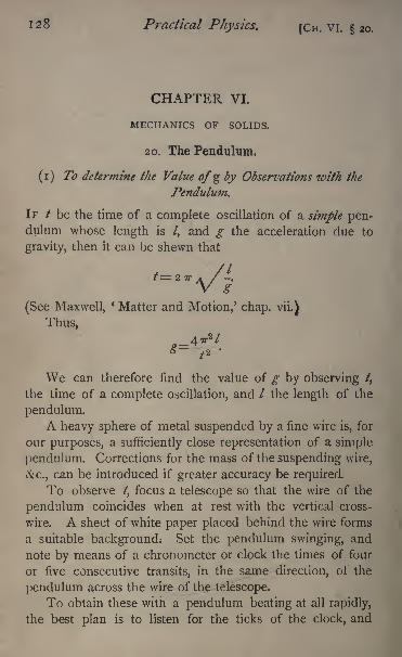
128 Practical Physics. [CH. VI. 20.
CHAPTER VI.
MECHANICS OF SOLIDS.
20. The Pendulum.
(i) To determine the Value ofgby Observations with the
Pendulum.
IF / be the time of a complete oscillation of a simple pen-dulum whose length is /, and g the acceleration due to
gravity, then it can be shewn that
(See Maxwell,' Matter and Motion,' chap, vii.)
Thus,
We can therefore find the value of g by observing /,
the time of a complete oscillation, and / the length of the
pendulum.A heavy sphere of metal suspended by a fine wire is, for
our purposes, a sufficiently close representation of a simple
pendulum. Corrections for the mass of the suspending wire,
&c., can be introduced if greater accuracy be required.
To observe /, focus a telescope so that the wire of the
pendulum coincides when at rest with the vertical cross-
wire. A sheet of white paper placed behind the wire forms
a suitable background; Set the pendulum swinging, and
note by means of a chronometer or clock the times of four
or five consecutive transits, in the same direction, or' the
pendulum across the wire of the telescope.
To obtain these with a pendulum beating at all rapidly,
the best plan is to listen for the ticks of the clock, and
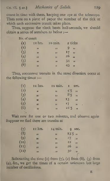
CH. VI. 20.] Mechanics of Solids. 129
count in time with them, keeping one eye at the telescope.
Then note on a piece of paper the number of the tick at
which each successive transit takes place.
Thus, suppose the clock beats half-seconds, we should
obtain a series of numbers as below :
10 min. 2 ticks
3J 9J 7 ,,
26>,
34
43
Thus, successive transits in the same direction occur at
the following times :
(1) ii hrs. 10 min. i sec.
(2) ,, 4'5 >
(3) 8-5
(4) i, 13
(5) J 7 .
(6) 21-5
Wait now for one or two minutes, and observe again
Suppose we find there are transits at
(7) 1 1 hrs. 14 min. 9 sec.
(8) 13-5
(9) *7
(10) 22
(n) 26
(12) 30
Subtracting the time (i) from (7), (2) from (8), (3) from
(9), &c., we get the times of a certain unknown but large
number of oscillations.
K
1 30 Practical Physics. (Cii. VI. 20.
The results are :
4 min. 8 sec.
9
8-5
9
9
8-5
The mean is 4 min. 8'66 sec.
Thus, in 248-66 sec. there is a large whole number of
complete oscillations.
Now, from our first series of observations we see that
five complete oscillations occupy 20-5 sec. Thus, the time
of an oscillation deduced from this series is ^ of 20-5
or 4-1 sec. From the second series the time of an oscilla-
tion is ^ of 21, or 4-2 sec.
Thus, the time of a complete oscillation deduced from
these two sets of observations is 4*15 sec.
If this were the true time of an oscillation, it would
divide 248-66 sec. exactly. On doing the division, the
quotient obtained is 59^92 sec.
This is very nearly 60, and since there has been a whole
number of oscillations in the 248*66 sec. we infer that whole
number must have been 60.
The time of an oscillation is therefore
The above is a specimen of the method generally
employed to obtain an accurate measure of the time of an
oscillation. It turns upon measuring roughly the time of oscil-
lation and then determining the exact number of oscillations
in a considerable interval by dividing the interval by the ap-
proximate measure of the time of oscillation, and selecting
the nearest integer. One very important point in reference
to this requires notice. Consider the instance quoted above.
CH. VI. 20.] Mechanics of Solids. 131
The rough value of the time of oscillation was determined by
observing the time of five oscillations with a clock shewinghalf-seconds. We must therefore consider the observation
of the first and sixth transit as each liable to an error of half
a second ;that is, the time of the five oscillations is liable to
an error of one second, and the calculated time of one is
only to be regarded as accurate within 0-2 sec.
All we can be sure of, therefore, is that the time of an
oscillation lies between 3-95 sec. and 4-35 sec. Now the
nearest integer to 248-66/3-95 is 63, and the nearest integer
to 248-66/4-35 is 57 ; hence, without more observations than
have been indicated above, we are not justified in taking 60
as the proper integral number of oscillations during the
interval. All we really know is that the number is one of
those between 57 and 63.
In order that there may be no doubt about the proper
integer to select, the possible error in the rough value of the
time of oscillation, when multiplied by the integer found,
must give a result less than half the time of an oscillation;
thus in the instance quoted the inference drawn is a safe
one, provided 4' 15 sec. represents the period of one oscilla-
tion to the thirtieth of a second. If this be the case the
method given above will indicate the proper integer to select
as representing the number of oscillations in 248 sec., and
therefore give the time of an oscillation correct to about
the 25oth of a second.
There are two ways of securing the necessary accuracy in
the observed time of an oscillation : (i) by making a series
of thirty-one transit observations instead of 6, as indicated
above ; and (2) by repeating the process sketched, using
intervals sufficiently small for us to be certain that we can
select the right integer.
Thus, suppose six transit observations are made, the
second series must be made after an interval not greater
than 20 sec., a third after an interval of 60 sec. from the
first, a fourth after an interval of 140 sec. From the originalK2
132 Practical Physics. [CH. VI. 20.
series a result will be obtained accurate to 0*2 sec.;with the
first and second the accuracy can be carried to o'i sec., with
the first and third to 0^05 sec.;and so proceeding in this
way, we can with complete security carry the accuracy to
any extent desired.
To determine /, we measure the length of the suspend-
ing wire by means of a tape, and add one half of the
diameter of the bob as measured by the calipers. If the
value of gravity is to be expressed in C. G. S. units (cm.
per sec. per sec.), the length must be given in centimetres.
Thus the values of / and / have been found. Substituting
these in the formula for g, its numerical value may be found.
The value of TT being 3*142, we may generally put 7r2 =io
with sufficient accuracy.
(2) To compare the Times of Oscillation of two Pendulums.
Method of Coincidences.
The method is only applicable in the case of two pen-dulums whose periods of oscillation are very nearly in some
simple ratio which can be roughly identified.
The two pendulums are arranged one behind the other,
and a screen is placed in front with a narrow vertical slit.
A telescope is arranged so as to view through the slit
the nearer of the two wires. The second one is not visible,
being covered by the first.
Let us suppose that the shorter pendulum vibrates
rather more than twice as fast as the longer.
Start the two pendulums swinging ;the two wires will
appear to cross the slit at different moments. After a few
swings they will cross in the same direction at the same
moment.
We may notice that the shorter pendulum, besides
executing two oscillations while the longer executes one,
gradually gains on the latter, but after a time the two again
cross simultaneously in the same direction. Let us suppose
that this happens after 1 2 oscillations of the long pendulum ;
then there have been clearly 25 oscillations of the shorter
CH. VI. 20.] Mechanics of Solids. 133
in the same interval. Thus, the time of oscillation of the
short pendulum is
X4'i44, or 1*9889 sec.
If the longer pendulum had been gaining on the shorter,
the latter would have lost one oscillation during the interval,
and the ratio of the times of oscillation would have been
12 : 23.
Experiments.
(1) Determine by observations on a simple pendulum the
value of g.
(2) Compare the times of oscillation of the two pendulums.
Enter results thus :
(i) Approximate value of /(from 31 transits) . 4*15 sec.
Corrected value from an interval of
4 min. 8-66 sec...... 4*144
Length of suspending wire . . . 421*2 cm.
Radius of bob ...... 4'5
Value of / ....... 4257
_
(2) Ratio of times from rough observations . 2'i
Interval between coincidences twelve complete oscillations
of the longer (the shorter pendulum gaining on the
other).
Ratio of times . . . 2-083.
21. Atwood's Machine.
Two equal weights each of mass M are hung by a fine
string over a pulley.
A third weight of mass R is allowed to ride on one of
these two, thus causing it to descend. After it has fallen
through a measured distance, R is removed by means of a
ring, through which the weight carrying it can pass, while R
cannot.
The time which it takes for the weights to fall through
this measured distance is noted.
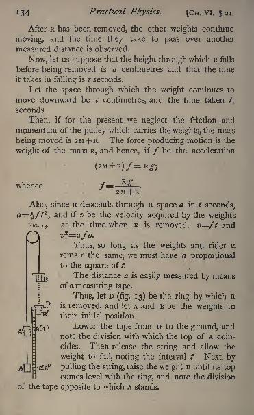
134 Practical Physics. [CH. VI. 21.
After R has been removed, the other weights continue
moving, and the time they take to pass over another
measured distance is observed.
Now, let us suppose that the height through which R falls
before being removed is a centimetres and that the time
it takes in falling is / seconds.
Let the space through which the weight continues to
move downward be c centimetres, and the time taken t\
seconds.
Then, if for the present we neglect the friction and
momentum of the pulley which carries the weights, the mass
being moved is 2M+ R. The force producing motion is the
weight of the mass R, and hence, if / be the acceleration
whence /= R<^.
2M + R
Also, since R descends through a space a in t seconds,
0=^//2
;and if v be the velocity acquired by the weights
FIG. 13. at the time when R is removed, v=ft andz/2=2fa.
Thus, so long as the weights and rider Rremain the same, we must have a proportionalto the square of t.
The distance a is easily measured by meansof a measuring tape.
Thus, let D (fig. 13) be the ring by which R? is removed, and let A and B be the weights in
their initial position.
r Lower the tape from D to the ground, and
note the division with which the top of A coin-
cides. Then release the string and allow the
weight to fall, noting the interval /. Next, by"
pulling the string, raise the weight B until its topcomes level with the ring, and note the division
of the tape opposite to which A stands.
CH. vi. 2i.] Mechanics of Solids. 135
The difference between these two readings gives the
distance a.
Thus, in the figure, A stands at 12 ft. 8 in., when B
comes to B' just passing the ring D, A has arrived at A', and
the reading is 8 ft. 4 in. Thus
fl=i2ft. 8 in. 8ft. 4 in.=4 ft. 4 in.= 132*08 cm.
We must now shew how the time / may be convenientlymeasured.
This may be done by means of a metronome, a clock-
work apparatus, which by adjusting a movable weight can
be made to tick any required number of times within
certain limits in a second. Adjust the weight so that
the rate of ticking is as rapid as can conveniently be
observed, and count the number of ticks in the time of
fall. It will be an advantage if the metronome can be so
adjusted that this shall be a whole number. Then determine
the number of ticks per second, either by the graduationsof the metronome or by taking it to a clock and countingthe ticks in a known interval, and thus express the time of
fall in seconds.
If a metronome is not obtainable, fairly accurate results
may be obtained by allowing mercury to flow from a small
nozzle through a hole in the bottom of a large flat dish,
and catching in a weighed beaker, and then weighing the
mercury which flows out while the weight is falling. The
weight of mercury which flows out in a known interval
of time is also observed, and by a comparison of the two
weights the time required is determined.
The time / should be observed at least twice for the
same fall a.
Now make the same observations with a different fall, a'
suppose, and shew that the law that the space traversed
varies as the square of the time is true.1
1 If the apparatus can be arranged so that the distance a can bevaried, more accurate results may be obtained by determining the value
1 36 Practical Physics. [Cn. VI. 21.
Now, let the weight B, after falling through the distance
a, deposit R upon the ring D, and observe the time required
by the weights A, B to pass over a further distance c;
let it
be /! seconds.
The weights move over the space c with uniform
velocity v;thus /b the time of fall, is inversely propor-
tional to v.
Now, v is the velocity acquired by falling through the
distance a; thus v is proportional to the square root
of a.
Thus, /, should be inversely proportional to the square
root of a, or t^ proportional to ija.
Thus, # /!2 should be constant, and equal to t^jzf.
Observe the value of /xfor various values of a, and shew
that a /!2
is constant.
From the last observations we can calculate the value of
g, the acceleration due to gravity.
For if/ be the acceleration produced by the weight of
the mass R,
/=-M_J 2M+ R*
/=_^=JiJ_,2tf/!
2 2M+ R
^--.
M and R are the number of grammes in the weights
used.
We have neglected the effect of the momentum pro-
duced in the pulley .and of friction.
We can allow for the former in the following manner :
of a, for which the time t is an exact multiple of theperiotf
of the clock
or metronome.
Cn. VI. 21.]Mechanics of Solids. 137
It can be shewn theoretically that its effect is practically
to increase the mass moved without altering the force
tending to produce motion. Thus we should include in
the mass moved a quantity w, which we can calculate by
theory, or better determine by experiment.
Thus, if/as before be the acceleration,
2M+ R +W
Repeat the observations, using the same value of c and
a, but altering the rider to R'; ^ will be changed to //, and
the acceleration will be/' where
But
Hence2a
8/T> / 2 T?///'2\_ T) T?/-^(RTi R Ft )
R R,
and
To eliminate the effect of friction we may determine
experimentally the least mass which we must attach to the
weight B in order just to start the apparatus. Let this be
F grammes. Then, if we assume the friction effect to be
constant throughout the experiment, the part of R which is
effective in producing acceleration is R F;we must there-
fore substitute R F for R throughout.It is probably not true that the frictional effect is the
same throughout; the apparatus is, however, so constructed
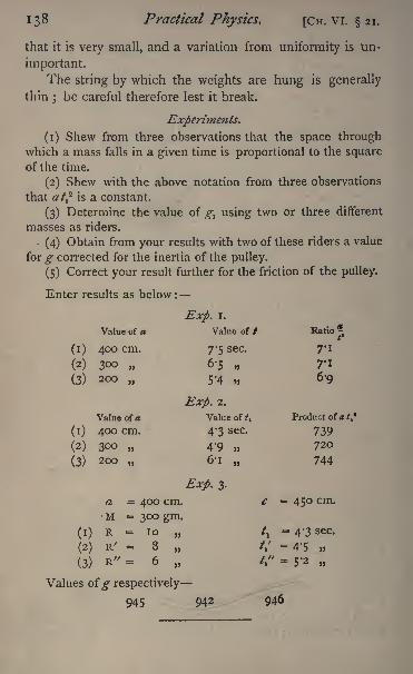
138 Practical Physics. [CH. vi. 21.
that it is very small, and a variation from uniformity is un-
important.
The string by which the weights are hung is generally
thin ; be careful therefore lest it break.
Experiments.
(1) Shew from three observations that the space throughwhich a mass falls in a given time is proportional to the squareof the time.
(2) Shew with the above notation from three observations
that at? is a constant.
(3) Determine the value of g^ using two or three different
masses as riders.
(4) Obtain from your results with two of these riders a value
for g corrected for the inertia of the pulley.
(5) Correct your result further for the friction of the pulley.
Enter results as below:
CH. VI.] Mechanics of Solids. 139
SUMMARY OF THE GENERAL THEORY OF ELASTICITY.
The elastic properties of an isotropic homogeneouselastic body depend on two qualities of the body viz. its
compressibility and its rigidity. The compressibility de-
termines the alteration in volume due to the action of
external forces, the rigidity the alteration in form.
Compressibility and Elasticity of Volume.
Suppose we have a body whose volume is v, and that it is
under a hydrostatic pressure P;
let the pressure be changedto P+/, and the volume in consequence to v v. Then
#/v is the change in unit volume due to the increment of
the pressure /, and z>/(v/) is the change per unit volume
due to unit increment of pressure.
This is called the compressibility of the body, which
may be defined as the ratio of the cubical compression per
unit volume to the pressure producing it. The reciprocal
of the compressibility viz. the value of vplv is the elas-
ticity of volume. We shall denote it by k.
Rigidity.
Any alteration of form or of volume in a body is accom-
panied by stresses and strains throughout the body.A stress which produces change of form only, without
alteration of volume, is called a shearing stress.
Imagine one plane in the body to be kept fixed while all
parallel planes are moved in the same direction parallel to
themselves through spaces which are proportional to their
distances from the fixed plane ;the body is said to undergo
a simple shear.
Suppose further that this simple shear is produced bythe action of a force on a plane parallel to the fixed plane,and uniformly distributed over it ; then the ratio of the force
per unit of area to the shear produced is defined to be the
rigidity of the body.
1 40 Practical Physics. [Cn. VI.
Let T be the measure of the force acting on each unit of
area of the plane, and suppose a plane at a distance a from
the fixed plane is moved through a distance c\ then c\a is
defined as the measure of the shear, and the rigidity of the
body is ta\c.Let us call this n. It may be shewn mathematically
that, if a circular cylinder of radius r and length / be held
with one end fixed, the couple required to turn the other
end through an angle 6 is n"
6.21
Modulus of Torsion.
The couple required to twist one end of unit length of a
wire through unit angle, the other end of the wire being kept
fixed, is called the modulus of torsion of the wire.
Hence if r be the modulus of torsion, the couple re-
quired to twist one end of a length / through an angle 6, the
other end being kept fixed, is rdjl.
Relation between Modulus of Torsion and Rigidity.
We have given above two expressions for the couple
required to twist one end of a length / of a wire of cir-
cular section through an angle 0, the other end being keptfixed
; equating these two expressions we get for a wire of
radius rt
2Tn = ,.
itr*
Young's Modulus.
If an elastic string or wire of length / be stretched by a// 7
weight w until its length is /', it is found that - is constant/ w
for that wire, provided that the wire is not strained beyondthe limits of perfect elasticity; that is, the weight w must
be such that, when it is removed, the wire will recover its
original length.
If the cross section of the wire be of unit area, the ratio

CH. VI. 22.] Mechanics of Solids. 141
of the stretching force to the extension per unit length is
called Young's Modulus, for the material of which the wire
is composed, so that if the cross section of the wire be w sq. cm.
and we denote Young's Modulus by E, we have
E=
Relation between Young's Modulus and the Coefficients of
Rigidity and Volume Elasticity.
We can shew from the theory of elasticity (see Thomson,Ency. Brit. Art.
'
Elasticity '),that if E be Young's Modulus,
and hence
r
3 3-Thus, knowing E and n, we can find k.
22. Young's Modulus.
To determine Young's Modulus for copper, two pieces
of copper wire seven or eight metres in length are hung from
the same support. One wire carries a scale of millimetres
fixed to it so that the length of the scale is parallel to the
wire. A vernier is fixed to the other wire,1
by means of
which the scale can be read to tenths of a millimetre. Thewire is prolonged below the vernier, and a scale panattached to it
;in this weights can be placed. The wire
to which the millimetre scale is attached should also carry a
weight to keep it straight. Let us suppose that there is a
weight of one kilogramme hanging from each wire.
Measure by means of a measuring tape or a piece of
string the distance between the points of suspension of the
1 We believe that we are indebted indirectly to the Laboratoryof King's College, London, for this elegant method of reading the
extension of a wire.
142 Practical Physics. [CH. VI. 22.
wires and the zero of the scale. Let this be 716*2 centi-
metres.
Now put into the pan a weight of 4 kilogrammes, and read
the vernier. Let the reading be 2-56 centimetres.
The length of the wire down to the zero of the vernier is
therefore 71876 centimetres.
Now remove the 4 kilogramme weight from the pan.
The vernier will rise relatively to the scale, and we shall
obtain another reading of the length of the wire down to the
zerp of the vernier. Let us suppose that the reading is
0-23 centimetre. The length of the wire to which the
millimetre scale is attached is unaltered, so that the new
length of the wire from which the 4 kilogramme weight has
been removed is 718-53 centimetres.
Thus, 4 kilogrammes stretches the wire from 718-53 centi-
metres to 718-76 centimetres. The elongation, therefore, is
0-23 centimetre, and the ratio of the stretching force to the
extension per unit length is
- '
3, or 12500 kilogrammes approximately.
We require the value of Young's Modulus for the
material of which the wire is composed. To find this we
must divide the last result by the sectional area of the wire.
If, as is usual, we take one centimetre as the unit of
length, the area must be expressed in square centimetres.
Thus, if the sectional area of the wire experimented on
above be found to be o-oi square centimetre (see 3), the
value of the modulus for copper is
I2 500,or 1250000 kilogrammes per square centimetre.
"OI
The modulus is clearly the weight which would double
the length of a wire of unit area of section, could that be
done without breaking it.
Thus, it would require a weight of 1,250,000 kilo-
CH. VI. 22.] Mechanics of Solids. 143
grammes to double the length of a copper wire of one squarecentimetre section.
The two wires in the experiment are suspended from the
same support. Thus, any yielding in the support produced
by putting on weights below or any change of temperatureaffects both wires equally.
It is best to take the observations in the order given
above, first with the additional weight on, then without it,
for by that means we get rid of the effect of any permanent
stretching produced by the weight.
The wire should not be loaded with more than half the
weight required to break it. A copper wire of o'oi sq. cm.
section will break with a load of 60 kgs. Thus, a wire of 0*01
sq. cm. section may be loaded up to 30 kgs. The load
required to break the wire varies directly as the cross-
section.
To make a series of determinations, we should load the
wire with less than half its breaking strain, and observe the
length ; then take some weights off say 4 or 5 kgs. if the
wire be of about 0*0 1 sq. cm. section, and observe again ;
then take off 4 or 5 kgs. more, and observe the length ; and
so on, till all the weights are removed.
The distance between the point of support and the zero
of the millimetre scale, of course, remains the same through-out the experiment. The differences between the readingsof the vernier give the elongations produced by the corre-
sponding weights.
The cross-section of the wire may be determined by
weighing a measured length, if we know, or can easily find,
the specific gravity of the material of which the wire is made.
For, if we divide the weight in grammes by the specific
gravity, we get the volume in cubic centimetres, and dividingthis by the length in centimetres, we have the area in squarecentimetres.
It may more readily be found by the use of Elliott's
wire-gauge (see 3).
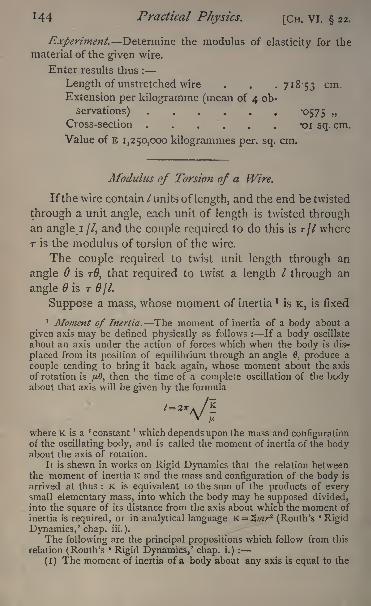
144 Practical Physics. [CH. VI. 22.
Experiment. Determine the modulus of elasticity for the
material of the given wire.
Enter results thus :
Length of unstretched wire . . .718-53 cm.
Extension per kilogramme (mean of 4 ob-
servations) '0575Cross-section -01 sq. cm.
Value of E 1,250,000 kilogrammes per. sq. cm.
Modulus of Torsion of a Wire.
Ifthe wire contain /units of length, and the end be twisted
through a unit angle, each unit of length is twisted throughan angle i //, and the couple required to do this is r// where
T is the modulus of torsion of the wire.
The couple required to twist unit length through an
angle 6 is TO, that required to twist a length / through an
angle is T Of I.
Suppose a mass, whose moment of inertia *is K, is fixed
1 Moment of Inertia. The moment of inertia of a body about a
given axis may be defined physically as follows : If a body oscillate
about an axis under the action of forces which when the body is dis-
placed from its position of equilibrium through an angle 0, produce a
couple tending to bring it back again, whose moment about the axis
of rotation is /u.8, then the time of a complete oscillation of the bodyabout that axis will be given by the formula
where K is a 'constant' which depends upon the mass and configuration
of the oscillating body, and is called the moment of inertia of the bodyabout the axis of rotation.
It is shewn in works on Rigid Dynamics that the relation betweenthe moment of inertia K and the mass and configuration of the body is
arrived at thus : K is equivalent to the sum of the products of everysmall elementary mass, into which the body may be supposed divided,into the square of its distance from the axis about which the moment of
inertia is required, or in analytical language K = 2///r2 (Routh's 'Rigid
Dynamics,' chap. iii.).
The following are the principal propositions which follow from this
relation (Routh's'
Rigid Dynamics,' chap, i.) :
(i) The moment of inertia of a body about any axis is equal to the
Cir. VI.] Mechanics of Solids. 145
rigidly to the wire, which is then twisted, the mass will
oscillate, and if /, sec. be the time of a complete oscillation,
it can be shewn that
To find T, then, we require to measure f}and K.
K can be calculated if the body be one of certain deter-
minate shapes.
If not, we may proceed thus : We can alter the momentof inertia of the system without altering the force tending to
bring the body, when displaced, back to its position of equili-
brium, either (i) by suspending additional masses of known
shape, whose moment of inertia about the axis of rotation
can be calculated, or (2) by altering the configuration of the
mass with reference to the axis of rotation. Suppose that
in one of these two ways the moment of inertia is changed
sum of the moments of inertia of its separate parts about the sameaxis.
(2) The moment of inertia of a body about any axis is equal to the
moment of inertia of the body about a parallel axis through the centre of
gravity together with the moment of inertia of a mass equal to the mass of
the body supposed collected at its centre of gravity about the original axis.
(3) The moment of inertia of a sphere of mass M and radius a abouta diameter is Ma-.
(4) The mpment of inertia of a right solid parellelepiped, mass M,whose edges are 20, 2^, 2c about an axis through its centre perpen-dicular to the plane containing the edges b and c is
3
(5) The moment of inertia of a solid cylinder mass M and radius rabout its axis of figure is
2
about an axis through its centre perpendicular to the length of the
cylinder,//a
where 2/ is the length of the cylinder.It is evident from the fact that in calculating the moment of inertia
the mass of each element is multiplied by the square of its distance fromthe axis, the moment of inertia will in general be different for different
dis r ributions of the same mass with reference to the axis.
L
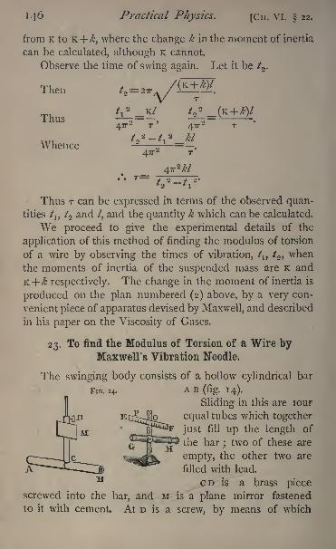
146 Practical Physics. [CH. VI. 22.
from K to K + ,where the change k in the moment of inertia
can be calculated, although K cannot.
Observe the time of swing again. Let it be t2 .
T-U /(K+ /<?)/Then t.2 2.Tr*/
/ 2 K 7 / 2 /
Thus -^=-, -^=-
Whence47T
2
Thus T can be expressed in terms of the observed quan-tities /
1}/2 and /, and the quantity which can be calculated.
We proceed to give the experimental details of the
application of this method of finding the modulus of torsion
of a wire by observing the times of vibration, /1}
/2 ,when
the moments of inertia of the suspended mass are K and
K+/& respectively. The change in the moment of inertia is
produced on the plan numbered (2) above, by a very con-
venient piece of apparatus devised by Maxwell, and described
in his paper on the Viscosity of Gases.
23. To find the Modulus of Torsion of a Wire byMaxwell's Vibration Needle.
The swinging body consists of a hollow cylindrical bar
FIG. 14. A B(fig. 14).
Sliding in this are lour
equal tubes which together
just fill up the length of
the bar ; two of these are
empty, the other two are
filled with lead.
CD is a brass piecescrewed into the bar, and M is a plane mirror fastened
to it with cement. At D is a screw, by means of which
CH. VI. 23.] Mechanics of Solids. 147
the bar is secured to the wire of which the modulus is re-
quired. E F is a horizontal scale placed so as to be re-
flected in the mirror M, and G H is a telescope adjusted to
view the image of E F produced by the mirror. The eye-
piece of the telescope is provided with cross-wires.
The first adjustment necessary is to arrange the apparatusso that when the bar is at rest the central division of. the
scale, which should be placed just above the telescope, ap-
pears, in the field of view of the telescope, to be nearly
coincident with the vertical cross-wire. The mirror must be
adjusted either by loosening the screw D and turning the
bar round, or by turning the support which carries the wire,
until when in the position of rest the plane of the mirror
is very nearly at right angles to M G.
When this is done, reduce the bar as nearly as possible
to rest, and point the telescope towards the mirror. For
this purpose focus the telescope on the mirror, move it until
the mirror is seen in the centre of the field, and then fix it
with a clamp.Alter the focus of the telescope so as to view an object
at about the same distance behind the mirror as the scale
is in front.
For the present this may be done quite roughly, by
slightly pushing in the eye-piece.
If the scale happen to be in adjustment, the image will
be seen in the mirror.
If this be not the case, move your head about behind
the telescope until the scale is seen reflected in the mirror.
Notice the position of your eye with reference to the tele-
scope, and infer from this how the scale requires to be moved
Thus, if your eye is above the telescope, the scale is too
low, and vice versa.
Move the scale in the direction required until it is in the
field of view of the telescope, and fix it securely.
There is another way of performing this adjustment,which may sometimes prove more rapid. Looking through
L 2
148 Practical Physics. [CH. VI. 23.
the telescope, move a lighted lamp or match about until a
glimpse of it is caught reflected in the mirror. The positionof the lamp at that moment shews you where the scale
should be.
(If the first method be adopted, it is easier to see the
scale by going close up to the mirror until it comes into
view, and then moving backwards to the telescope, still
keeping it in sight.)
Suppose now the scale is seen reflected from the mirror;the central division of the scale will probably not coincide
with the cross-wire.
For many purposes this is unimportant. If, however,we wish to bring the two together we must notice what pointon the scale will come opposite the cross-wire when the
mirror is at rest,1 and then turn the torsion head, which carries
the wire in the right direction until the central division is
brought into view.
It may be impossible to make the adjustment in this
manner;in that case we must move the telescope and scale.
Thus, if o be the central division of the scale and p the
division which coincides with the cross-wire, the necessary
adjustment will be made if we move the telescope and scale
through halfthe distance o p, still keeping the former pointedto the mirror.
It is sometimes necessary to set the scale at right anglesto M o or M G. For this purpose measure with a string or
tape the distances of E M and F M, and turn the scale round
a vertical axis until these two are equal. Then since o E=o F
and M E=M F, it is clear that o M and E F are at right angles,
and the required adjustments are complete.
To observe the Time of a Complete Vibration.
Twist the bar slightly from its position of rest, and let it
vibrate.
1 When the position on the scale of the {
turning-points' of the
needle can be read through the telescope, the position ofequilibrium canbe determined in exactly the same manner as in the case of the balance
(see 12).
CH. vi. 23.] Mechanics of Solids 149
The scale will appear to cross the field of view of the
telescope.
Note with a watch or chronometer the instant at which
the middle point of the scale passes the cross- wire of the
telescope, marking also the direction in which the scale
appears to be moving. Let us suppose it is from left to
right. It is of course impossible to see at the same time the
cross-wire and scale and also the face of the chronometer ;
but the observation may be effected either as described
in ii or as follows.
Let us suppose the chronometer ticks half-seconds.
Listen carefully for the sound of the tick next after the
transit of the central division of the scale, and count six in
time with the ticks, moving at the same time the eye from
the telescope to the clock-face. Suppose that at the sixth
tick the chronometer registers 10 h. 25 min. 31*5 sec, then
the instant of transit was 3 sec. earlier, or 10 h. 25 min,
28-5 sec. Raise the eye quickly back to the telescopeand watch for the next transit from left to right.
Again count six ticks, moving the eye to the chronometer,and let the time be 10 h. 26 min. 22 sec.
The time of the second transit is then 10 h. 26 min.
19 sec., and the time of a complete vibration is 50-5 sec.
But either observation may be wrong by -5 sec., so that
this result is only accurate to within i sec.
To obtain a more accurate result proceed exactly as in
20.
It may happen that the time of vibration is so short
that we have not time to perform all the necessary operations
namely, to move the eye from the telescope, look at the
chronometer, note the result, and be ready for another
transit before that transit occurs. In such a case we must
observe every second or third transit instead of each one.
Again, we may find that 6 ticks do not give time to
move the eye from the telescope to the chronometer- face. If
this be so, we must take 8 or 10. Practice, however, soon
renders the work more rapid.
150 Pracncal Physics. [Cn. VI. 23.
Of course, if we always count the same number of ticks
there is no need to subtract the 3 sec. from the chronometer
reading ; we are concerned only with the differences be-
tween the times of transit, and the 3 sec. affects all alike.
We may thus observe /1} the time of vibration of the
needle when the empty tubes are nearest the ends, the loaded
tubes being in the middle ; and in the same manner we mayobserve /2 ,
tne time of vibration of the needle when the
positions of the heavy and light tubes have been inter-
changed. Let the observed value of /xbe 17*496 sec.,
and that of /2 , 25*263 sec.
To find the Value of A, the Increase in the Moment ofInertia.
We know that the moment of inertia of a body about
any axis is equal to its moment of inertia about a parallel axis
through its centre of gravity, together with the moment of
inertia of the whole mass collected at its centre of gravity
about the given axis (p. 44).
Thus, let m be the mass of a body whose moment of
inertia about a certain axis is I;
let a be the distance of
the centre of gravity from that axis, and I the moment of
inertia about a parallel axis through the centre of gravity.
Then 1=1+ ma2.
Moreover, the moment of inertia of a body is the sumof the moments of inertia of its parts (p. 44).
Now, let ;;/! be the mass of each of the heavy tubes, and
a the distance of the centre of each of them from the axis
round which the whole is twisting when in the first position.
Let ILbe the moment of inertia of each of the heavy tubes
about a parallel axis through its centre. Let ;;/ 2,I 2 have the
same meaning for the empty tubes, and let b be the distance
of the centre of each of these from the axis of rotation.
Let I be the moment of inertia of the empty case.
Then
CH. VI. 23.]MecJianics of Solids. .151
In the second position, a is the distance from the axis of
roiation of the centre of each of the masses m 2 ,b of that of
the masses m{
.
To find the moment of inertia of the whole, therefore,
we require simply to interchange a and b in equation (i),
and this moment of inertia is K + /. Thus,
K+/=I+ 2l1 + 2l 2+ 2///
1
2 ^ 2 ;// 22
. . . . (2).
from (i) and (2) k= 2(b2
a^) (m l;// 2 ).
Thus, we do not need to know I, Ij or I 2 to find k.
Now the length of each of the tubes is one-fourth oi
that of the whole bar A B. Calling this c, we have
and ^
To find MI and m z ,we require merely to determine
by weighing the number of grammes which each contains.
Our formula for r (p. 146) becomes
_
and it only remains to measure /. This can be done bymeans of the beam compass or a measuring tape.
We must, of course, measure from the point at which
the upper end of the wire is attached, to the point at which
it is clipped by the screw D.
The wire it will be found fits into a socket at the top of
the apparatus CD. Be careful when fixing it initially to
push it as far as possible into the socket;
its position can
then be recovered at any time.
Unloose the screw D and draw the wire from above, up
through the tube which supports it, and measure its lengthin the ordinary manner.
The value of r thus obtained gives the modulus of torsion
for the particular specimen of wire. If the modulus of torsion
for the material is required, we must make use of the addi-
1 52 Practical Physics. [CH. VI, 23.
tional law of torsional elasticity that the torsional couple in
wires of the same material, differing only in area of section,
is proportional to the fourth power of the radius of the wire.
To find the value of the modulus of torsion of the material,
the value of r must be divided by \-nr^ where r is the radius
in centimetres (p. 140).
Experiment. Determine the modulus of torsion of the givenwire.
Enter results thus :
/!-
5-95 sec. /2 =975 sec.
1ll\= 35 !
'
2 5 Sms wa= 60-22 gms.
/ = 57*15 cm. c =45'55 cm.
r = '67 x io6.
CHAPTER VII.
MECHANICS OF LIQUIDS AND GASES.
Measurement of Fluid Pressure.
THE pressure at any point of a fluid is theoretically
measured by the force exerted by the fluid upon a unit
area including the point. The unit area must be so small
that the pressure may be regarded as the same at every
point of it, or, in other words, we must find the limiting
value of the fraction obtained by dividing the force on an
area enclosing the point by the numerical measure of the
area, when the latter is made indefinitely small.
This theoretical method of measuring a pressure is not
as a rule carried out in practice. On this system of measure-
ment, however, it can be shewn that the pressure at any
point of a fluid at rest under the action of gravity is uniform
over any horizontal plane, and equal to the weight of a
column of the fluid whose section is of unit ifrea, and whose
length is equal to the vertical height of the free surface of
the heavy fluid above the point at which the pressure is
required. The pressure is therefore numerically equal to the

CH. VII 24.] Mechanics of Liquids arid Gases. 153
weight of ph units of mass of the fluid, where p is the mean
density of the fluid, h the height of its free surface above
the point at which the pressure is required.
This pressure expressed in absolute units will be gph,where g is the numerical value of the acceleration of gravity.
If the fluid be a liquid, p will be practically constant for
all heights ; g is known for different places on the earth's
surface.
The pressure will therefore be known if the height h be
known and the kind of liquid used be specified.
This suggests the method generally employed in practice
for measuring fluid pressures. The pressure is balanced bya pressure due to a column of heavy liquid e.g. mercury,
water, or sulphuric acid and the height of the column
necessary is quoted as the pressure, the liquid used being
specified. Its density is known from tables when the tem-
perature is given, and the theoretical value of the pressure in
absolute units can be deduced at once by multiplying the
height by g and by p, the density of the liquid at the tempe-rature.
If there be a pressure II on the free surface of the liquid
used, this must be added to the result, and the pressure
required is equal to II -\-gph.
Example. The height of the barometer is 755 mm., the
temperature being 15 C: find the pressure of the atmosphere.
The pressure of the atmosphere is equivalent to the weightof a column of mercury 75-5 cm. high and I sq. cm. area, and= 981 in C.G.S. units.
The density of mercury is equal to I3'596 (i '00018 < 15)
gm. per c.c.
In the barometer there is practically no pressure on the free
surface of \he mercury, hence the pressure of the atmosphere= 981 x 13-596 (i -.00018 x 15) x 75-5 dynes per sq. cm.
24. The Mercury Barometer.
Barometers are of various forms ; the practical details
given here are intended with reference to the Fortm Standard
154 Practical Physics. [CH. VII. 24.
Barometer, in which the actual height of the column of
mercury, from the surface of the mercury in the cistern, is
measured directly by means of a scale and vernier placed
alongside the tube. The scale is only graduated between
twenty-seven and thirty-two inches, as the barometric heightat any ordinary observatory or laboratory is never outside
these limits.
To set and read the Barometer.
The barometer must first be made to hang freely, by
loosening the three screws at the bottom of the frame, in
order that the scale may be vertical.
The mercury in the cistern must be brought to the same
level as the zero point of the scale. This zero point is in-
dicated by a small ivory point ;and the extremity of this
point must first be made to coincide with the surface of
the mercury.This is attained by adjusting the bottom of the cistern
by means of a screw which projects from the bottom of the
barometer; raising this screw raises the mercury surface.
On looking at the surface a reflexion of the pointer is seen.
Raise the surface until the end of the pointer and its reflected
image appear just to touch. Then the mercury surface and
the zero of the scale are at the same level.
The upper surface of the mercury is somewhat convex.
In taking a reading, the zero of the vernier must be broughtto the same level as the top point of this upper surface.
Behind the barometer tube is placed a sheet of white
paper, and by raising the vernier this can be seen, throughthe tube, between it and the upper surface of the mercury.
Lower the vernier until,1
looking horizontally, it is just
impossible to see the white paper between it and the top
of the meniscus;then the zero of the vernier coincides with
the top of the mercury column. To be able to make sure
that the eye looks horizontally the vernier is provided with a
brass piece or. the opposite side of the tube, the lower edge1 See Frontispiece, fig. 2.
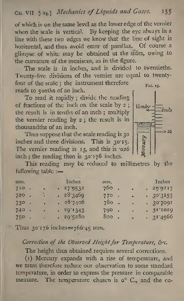
FIG. 15.
CH. VII 524.] Mechanics of Liquids and Gases. 155
of which is on the same level as the lower edge of the vernier
when the scale is vertical. By keeping the eye always in a
line with these two edges we know that the line of sight is
horizontal, and thus avoid error of parallax. Of course a
glimpse of white may be obtained at the sides, owing to
the curvature of the meniscus, as in the figure.
The scale is in inches, and is divided to twentieths.
Twenty-five divisions of the vernier are equal to twenty-
four of the scale;the instrument therefore
reads to 5ooths of an inch.
To read it rapidly ;divide the reading
of fractions of the inch on the scale by 2;
the result is in tenths of an inch; multiply
the vernier reading by 2 ; the result is in
thousandths of an inch.
Thus suppose that the scale reading is 30inches and three divisions. This is 30*15.
The vernier reading is 13, and this is '026
inch; the reading then is 30*176 inches.
This reading may be reduced to millimetres by
following table :
Seeds'
30
the
mm.
710
720
730
740
75
Inches
27*9532
28-3469
287406
29^34329-5280
mm.
760
770
780
790800
Inches
29-9217
30-7091
31-1029
31-4966
Thus 30*176 inches=766'45 mm.
Correction of the Observed Heightfor Temperature, 6<r.
The height thus obtained requires several corrections.
(i) Mercury expands with a rise of temperature, andwe must therefore reduce our observation to some standard
temperature, in order to express the pressure in comparablemeasure. The temperature chosen is o C., and the co-
156 Practical Physics. [CH. VII. 24.
efficient of expansion of mercury is '00018 1 per i C. Thus,if / be the observed height and / the temperature, the heightof the equivalent column at o C. is /(i '00018 it). In
applying this correction, it is very often sufficient to use the
mean value, 760 mm. for /, in the small term '000181 //.
Now 760 x 000181= -i 38. Then we can get the corrected
height with sufficient approximation by subtracting from the
observed height '138 x/. Thus if the observed height be
766*45 mm. and the temperature 15, the true height, so
far as this correction only is concerned, is
766-45-15 X'i38=766'45-2-o7= 764'38 mm.
(2) The same rise of temperature has caused the brass
scale to expand, so that the apparent height of the column
is on that account too short. To obtain the true height we
must add to the observed height /, the quantity //3/, ft beingthe coefficient of linear expansion of brass.
Now /3= '000019. The complete correction then due to
both causes will be ('00018 1 -000019) //, and the true
height is / ('000181 '000019) //or / -('00016 2)//.
If in the small term, (-oooi62)//, we take the mean
value, 760 mm., for /, the true height is,where b=l '123 1.
Thus in our case /=i5,
=766*45 i'85= 764'6o mm.
(3) Owing to the capillary action between the glass of
the tube and the mercury, the level of the mercury is de-
pressed by a quantity which is roughly inversely proportional
to the diameter of the tube. The depression is not practi-
cally of an appreciable amount unless the tube has a diameter
less than a centimetre.
In the instrument in the Cavendish Laboratory the tube
is 5*58 mm. in radius, and in consequence the top of the
meniscus is depressed by about '02 mm.;we must there-
fore add this to the observed height, and we find that the
corrected value of the height is 767*62 mm.
(4) Again, there is vapour of mercury in the tube, which
CH. VII. 24.] Mechanics of Liquids and Gases. 157
produces a pressure on the upper surface of the column.
It is found that at temperature t this may be practically
taken to be equivalent to -002 x / mm. of mercury. Thus,
if the temperature be 15, we must on this account add to
the observed height -03 mm., and we obtain as" our corrected
height 764-65 mm. This is the true height of the column
of mercury at standard temperature, which gives a pressure
equivalent to the pressure of the atmosphere at the place
and time in question.
(5) Now the weight of this column is balanced against the
pressure of the air. The weight of the column will dependon its position relatively to the earth. We must therefore
determine the height of the column which at some standard
position will weigh as much as our column. We take for
that standard position sea-level in latitude 45.Let^ be the value of the acceleration due to gravity at
this position, b$ the height of a column weighing the sameas our column b ; g the acceleration due to gravity at the
point of observation.
Then, since the weights of these two columns are the
same, we have bQgQ= bg> and therefore bQ bg/gQ .
Now it is known from the theory of the figure of the earth
that if h is the height above the sea-level in metres and< the latitude of the place of observation,
=1 '0026 COS 2 <f> *OOOOOO2&b
Hence=
(i -0026 cos 2 < '0000002^).
Experiment. Read the height of the standard barometer,and correct to sea-level at 45 lat.
25. The Aneroid Barometer.
In the aneroid barometer at the Cavendish Laboratoryeach inch of the scale is divided into fiftieths, and there
is a vernier,1
twenty half-divisions of which coincide with
1 See Frontispiece, fig. 4.
158 Practical Physics. [CH. VII. 25.
twenty-one of the scale;the vernier reads, therefore, by
estimation to thousandths of an inch. On the vernier each
division must be counted as two, only the even divisions
being marked.
The aneroid is set by comparison with a corrected mer-
cury barometer, to give the true pressure at the time of the
observation. If properly compensated for temperature, it
would continue to give the true barometric height at anyother station, even if the temperature changes.
To read the aneroid, set the zero of the vernier exactly
opposite the end of the pointer, and read the inches and
fiftieths on the scale up to the vernier zero.
Multiply the fractional divisions by 2;the result is in
hundredths of an inch. Read the vernier, and again multiply
by 2; the result is in thousandths of an inch.
(The numbers marked on the scale give tenths of an inch;
those on the vernier thousandths.)Thus the scale reading is between 30 and 31, the
pointer standing between divisions 12 and 13. The scale
reading, therefore, is 30-24. When the zero of the vernier
is opposite the pointer there is a coincidence at division
8 of the vernier;the vernier reading is, therefore, -016,
and the exact height is 30-256.
To measure the height between two stations with the
aneroid, take the reading at the two stations and subtract.
The difference gives the pressure in inches of mercury of
the column of air between the two.
Thus suppose that at a lower station the reading of the
aneroid is 30-276, and the difference in pressure is that dueto 0-020 inch of mercury ;
this is equivalent to 0-51 mm.The specific gravity of mercury is 13*60 ; thus '51 mm.
mercury is equivalent to -51 x 13-60 mm. of water at 4 C.
To find the true height of the column of air which is
equivalent in pressure to this, we must divide by the specific
gravity of air at the temperature and pressure of obser-
vation. This may be determined when the pressure and
Cn. VII. 25.] Mechanics of Liquids and Gases. 159
temperature have been observed, by calculation from the
data given in No. 36 of Lupton's' Tables.'
If the difference of height is not great the pressure of
the air between the two stations may, for this purpose, be
taken to be the mean of the aneroid readings at the two
stations, properly corrected by reference to the mercurystandard. For the temperature, if there is any considerable
difference between the thermometer readings at the two
stations, some judgment must be used in order to get a mean
result which shall fairly represent the average temperatureof the air between the two. When these observations have
been made, we are in a position to calculate the specific
gravity of dry air under the given conditions. Since the
atmosphere always contains more or less moisture, a correc-
tion must be applied. Since the specific gravity of aqueous
vapour referred to air at the same temperature and pressure
is |, the correction may be made by calculating what would
be the specific gravity of the dry air if its pressure were
diminished by an amount equivalent to three-eighths of the
pressure of the water vapour it contains, as determined byobservation of the dew-point or other hygrometric method.
This correction is often so small as to produce no appre-ciable effect within the limits of accuracy of the pressure
readings. %
Thus if the mean ofthe pressure observations be 768 mm.,and the estimated mean temperature 15 C., the specific
gravity of dry air would be 0*001239, an^ if the observed
pressure of aqueous vapour be 10 mm., the corrected specific
gravity would be
768 fx TO
6
*
8- x "001239, or -001233.
Hence the height of the column of air between the two
station's is
S'**3-6q mm., or 563 cm.001233
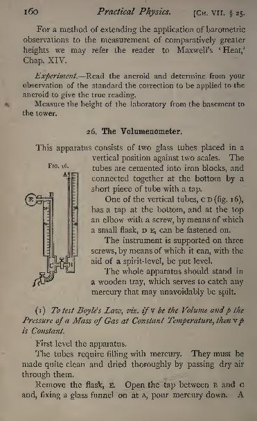
i6o Practical Physics. [CH. vn. 25.
FIG. 16.
For a method of extending the application of barometric
observations to the measurement of comparatively greater
heights we may refer the reader to Maxwell's 'Heat,'
Chap. XIV.
Experiment. Read the aneroid and determine from yourobservation of the standard the correction to be applied to the
aneroid to give the true reading.Measure the height of the laboratory from the basement to
the tower.
26. The Volumenometer.
This apparatus consists of two glass tubes placed in a
vertical position against two scales. Thetubes are cemented into iron blocks, and
connected together at the bottom by a
short piece of tube with a tap.
One of the vertical tubes, c D (fig. 16),
has a tap at the bottom, and at the top
an elbow with a screw, by means of which
a small flask, D E, can be fastened on.
The instrument is supported on three
screws, by means of which it can, with the
aid of a spirit-level, be put leveL
The whole apparatus should stand in
a wooden tray, which serves to catch any
mercury that may unavoidably be spilt.
(i) To test Boyle's Law^ viz. z/v be the Volume andp the
Pressure of a Mass of Gas at Constant Temperature^ then vpis Constant.
First level the apparatus.
The tubes require filling with mercury. They must be
made quite clean and dried thoroughly by passing dry air
through them.
Remove the flask, E. Open the tap between B and c
and, fixing a glass funnel on at A, pour mercury down. A
CH. VII. 26.] Mechanics of Liquids and Gases. 161
certain quantity of air will get carried down with the mer-
cury. This can generally be removed by tilting the apparatus,or by means of an iron wire. The mercury must be perfectly
clean and pure, otherwise it will stick to the glass and cause
endless trouble.
Let us suppose that the level of the mercury is the samein both tubes, standing at division 90, say. (The smaller
divisions of the scale at the Cavendish Laboratory are milli-
metres ; the numbered divisions are centimetres.)Screw on the flask gently, applying grease
l to the washer
to make it airtight.
Take care that the level of the mercury in the tubes
is not altered by screwing on the flask. This sometimes
happens from the heat of the hand causing the air inside to
expand ; then when the hand is removed the air inside
contracts and the level of the mercury is altered. This
may be avoided by screwing up the flask till it is almost
tight, then waiting a little till it acquires the tempera-ture of the room, and then completing the operation of
screwing.
Let v denote the volume of the air in the flask and
upper portion of the tube D c above the mercury that is,
down to the graduation 90. Since the mercury is at the
same height in both limbs, the pressure of the air in the flask
is the same as the pressure of the atmosphere, which we will
suppose to be that due to II mm. of mercury. Let us sup-
pose also that the volume of a length of the tube of i cm.
is v cubic centimetres.
Now open the tap c and let some mercury run out into
a beaker.
The level of the mercury will sink in both tubes, but it
will be found to be lower in A B than in c D.
Let us suppose that it stands at 72 in CD and 64 in A B.
1 A very good compound for this and similar purposes is easily made
by melting together equal quantities of pure vaseline and bees' wax. It
ihould when cold be tolerably firm, and is always ready for use.
M
:62 Practical Physics* [CH. VII. 26.
Then the difference in pressure in the two tubes is that
due to 72 64 cm. or 80 mm. of mercury.
The pressure in A B is II, that in D c then is II 80.
The volume of the air has been increased in consequenceof the diminution of pressure, by the volume of a length of
1 8 centimetres of the tube, and the 'volume of 18 centi-
metres is iSv;the new volume is therefore (v+ iSv).
Thus, applying Boyle's law,
(v + i8z>) (II-8o)=v n.
80 v^=i8z/(n 80)
_ i8z;(II-8o)80
If we know ?', this gives us a value for v on the assump-tion that Boyle's law is true.
We have yet to determine vtthe volume of i centimetre
of length of the tube.
This may be done previously to the experiment de-
scribed above in the following manner.
Fill the tubes with mercury and close the tap between
B and c. Open the tap at c and allow mercury to run out
from the tube c D, noting the division, 90 say, from which
it begins to run. Allow the mercury to run out for 20
or 25 centimetres (suppose till the level reaches 68), and
weigh the mercury. Let the weight be 30*26 grammes.The density of mercury is 13*6 gm. per c.c. Thus the
' ^0*26volume is 3 c.c.
13-6
This is the volume of a length of 22 cm.;thus v, the
volume of i cm.,
= 3'26
=-IQIC.C.I3'6 X 22
The determination of the volume of a centimetre of
the tube should be made three times for different parts in
order to calibrate the tube, 8.

CH. vil. 26.] Mechanics of Liquids and Gases. 163
Let us suppose that II, the height of the barometer, is
760. Then we find
v = 18 x -ioi x 8-5 = 15-45 c.c.
Now open the stop-cock at c again, let some more
mercury run out, and observe the difference of levels as
before. Calculating in the same way, we can get another
value for the volume v, and these two or more values thus
obtained should of course be the same, provided that Boyle'slaw is true. Thus a comparison of the values of v obtained
in this manner affords a verification of Boyle's law. There is
a liability to considerable error in the observations, in con-
sequence of alterations in the temperature of the air in the
flask. These must be guarded against as carefully as possible,
and, if greater accuracy be required, allowed for.
Before taking any of the readings to determine the dif-
ference of pressure, it is well to wait for a few minutes after
the mercuiy has been run out, and see if the level of the
mercury remains the same. If it does, we may feel sure
that there is no leakage from the joint at D.
(2) To determine by means ofthe Volumenometer the Density
of a Solid.
This method is applicable in the case of solids soluble
in or affected by water. The solid should be broken into
fragments sufficiently small to go into the flask D E.
Weigh the solid.
Determine as above the volume of the flask and portion
of the tube c D to the division 90.
Introduce the solid into the flask, and again deter-
mine the volume of the flask and tube c D to the samedivision 90. The difference between the two volumes is of
course the volume of the solid.
The density of the solid will be given by dividingthe mass in grammes by the volume in cubic centimetres.
M 2
164 Practical Physics. [CH. VII. 26.
The volume of the solid should be considerable ;it should
nearly fill the flask.
Experiments.
(1) Test Boyle's law by measuring the volume of a small
flask or test-tube attached to the volumenometer.
(2) Determine by means of the volumenometer the densityof the given light solid.
Enter results thus :
Vol. of i cm. length of tube . . . *ioi c.c.
Division to which tube is filled . . 90Amount run out 18 cm.
Difference of pressure . ... 80 mm. -
Height of barometer .... 760 mm.Volume 15-45 c.c.
CHAPTER VIII.
ACOUSTICS.
Definitions^ 6<r.
A MUSICAL note is the result of successive similar dis-
turbances in the air, provided that they follow each other
at regular intervals with sufficient rapidity. Similar dis-
turbances following each other at regular equal intervals are
said to be periodic. The interval of time between successive
impulses of a periodic disturbance determines the pitch of
the note produced that is, its position in the musical scale.
The pitch of a note is therefore generally expressed by the
number of periodic disturbances per second required to pro-
duce it. This number is called the ' vibration number,' or'
frequency'
of the note.
It generally happens that any apparatus for producing a
note of given frequency produces at the same time notes of
other frequencies. The result is a complex sound, equivalent
to the combination of a series of simple sounds or tones.
Cn. VIII. 26.] Acoustics. 165
The simple tones of which the complex sound may be re-
garded as consisting are called*
partial tones;
'
the gravest of
these that is, the one of lowest pitch is called the 'funda-
mental tone' of the sounding body, and the others are called
'
upper partials.' A note which has no upper partials is called
a pure tone. By means of suitable resonators the different
partial tones of a complex note may be made, very clearly
audible. For many musical instruments, as organ-pipes,
string instruments, &c., the ratio of the vibration frequency
of any upper partial tone to that of the fundamental tone is
a simple integer, and the upper partials are then called 'har-
monics;
'
for others, again, as for bells, tuning-forks, &c., the
ratios are not integral, and the upper partials are said to be
inharmonic.
27, To compare the Frequencies of two Tuning-forks of
nearly Identical Pitch, and to tune two Forks to
unison.
A tuning-fork mounted upon a resonator a wooden
box of suitable size furnishes a very convenient means of
obtaining a pure tone;the upper partials, which are gene-
rally heard when the fork is first sounded, are not reinforced
by the sounding box, and rapidly become inaudible, while
the fundamental tone is, comparatively speaking, permanent.When two forks which differ only slightly in pitch are set in
vibration together, the effect upon the ear is an alternation of
loud sound with comparative silence. These alternations
are known as beats, and they frequently are sufficiently well
marked and sufficiently slow for the interval of time between
successive beats to be determined with considerable accu-
racy by counting the number occurring in a measured
interval of time.
It is shewn in text-books on sound l that the number of
beats in any interval can be inferred from the vibration num-1
Deschanel, Natural Philosophy, p. 813; Stone, Elementary Lessons,
p. 72; Tyndall, On Sound, p. 261.
1 66 Practical Physics. [Cn. VI n. 27.
bers of the two notes sounded together, and that, if N be
the number of beats per second, n, n' the frequencies of the
two notes, n being the greater, then
N = n n'.
We have, therefore, only to determine the number of
beats per second in order to find the difference between the
frequencies of the two notes. This may be an easy or a
difficult matter according to the rapidity of the beats. If
they are very slow, probably only few will occur during the
time the forks are sounding, and the observer is liable to
confuse the gradual subsidence of the sound with the
diminution of intensity due to the beats. If, on the other
hand, there are more than four beats per second, it becomes
difficult to count them without considerable practice. The
difficulty is of a kind similar to that discussed in n, and
we may refer to that section for further details of the method
of counting.
In order to determine which of the two forks is the
higher in pitch, count the beats between them, and then
lower the pitch of one of them by loading its prongs with
small masses of sheet lead, or of wax (softened by turpen-
tine), and observe the number of beats again. If the number
of beats per second is now less than before, the loaded fork
was originally the higher of the two;
if the number of beats
has been increased by the loading, it is probable that the
loaded fork was originally the lower : but it is possible that
the load has reduced the frequency of the higher fork to
such an extent that it. is now less than that of the unloaded
second fork by a greater number than that of the second was
originally less than that of the first It is safer, therefore,
always to adjust the load so that its effect is to diminish the
number of beats per second, that is, to bring the two forks
nearer to unison;to do so it must have been placed on the
fork which was originally of the higher pitch.
In order to adjust two forks to unison, we may lower the
Or. VIII. 27.] Acoustics. 167
pitch of the higher fork by weighting its prongs until the
beats disappear ;the difficulty, already mentioned, when very
slow beats are observed occurs, however, in this case, and
it is preferable to use a third auxiliary fork, and adjust its
pitch until it makes, say, four beats a second with that one
of the two forks which is to be regarded as the standard,
noting whether it is above or below the standard. Thesecond fork may then be loaded so that it also makes- four
beats a second with the auxiliary fork, taking care that it is
made higher than the auxiliary fork if the standard fork
is so. The second fork will then be accurately in unison
with the standard a state of things which will probablybe shewn by the one, when sounded, setting the other in
strong vibration, in consequence of the sympathetic reso-
nance.
A tuning-fork may be permanently lowered in pitch by
filing away the prongs near their bases;on the other hand,
diminishing their weight by filing them away at their points
raises the pitch. Such operations should, however, not be
undertaken without consulting those who are responsible
for the safe custody of the forks.
Experiment. Compare the frequencies of the two givenforks A and'B by counting the beats between them. Determinewhich is the higher and load it until the two are in unison.
Enter results thus :
Number of beats in 25 sees. . . , .67Number per sec. ....... 2*7
(A loaded) 3-3
(B loaded). .... 2-1.
B is the higher fork.
Number of beats per sec. between A and' the
auxiliary fork c . . . . . . . 3 '6.
Number of beats per sec. between B (when
loaded) and. the auxiliary fork Q .. ... . 3-6,
1 68 Practical Physics. [CH. VIII. 28.
28. Determination of the Vibration Frequency of a Note
by the Siren.
A siren is essentially an instrument for producing a
musical note by a rapid succession of puffs of air. The
simplest form of siren is a large circular cardboard disc,
provided with perforations arranged in circles concentric
with the disc. The puffs of air may be produced by blow-
ing through a fine nozzle on to the circle of holes while the
disc is maintained in rapid rotation. In order that the dis-
turbances produced by the puffs of air passing through the
holes may be periodic (see p. 164), the holes must be
punched at equal distances from each other, and the disc
must be driven at a uniform rate. If the pressure of the
water-supply of the laboratory is sufficiently high, a small
water-motor is a convenient engine for driving the disc,
which must be mounted on an axle with a driving pulley.
If the diameter of the disc is considerable, so that a
large number of holes can be arranged in the circle, a
rotation of the disc giving four revolutions per second is
quite sufficient to produce a note of easily recognisable
pitch. The revolutions in a given interval, say, one minute,can be counted, if a pointer be attached to the rim of the
disc, and arranged so that it touches a tongue of paperfixed to the table once in every revolution. The number of
taps on this paper in a given time is the number of revolu-
tions of the disc. Suppose the number of taps in one
minute is N, and the number of holes in the circle which is
being blown is n, then the number of puffs of air produced
per minute is N #, and hence the number per second is
N n/6o.The disc is generally provided with a series of concen-
tric rings of holes differing in the number of perforations in
the 'circle, so that a variety of notes can be blown for the
same rate of rotation of the disc.
In the more elaborate forms of the instrument .a
CH. VIII. 28.] Acoustics. 169
disc, which is perforated with holes arranged in concentric
circles, is mounted on a spindle so that it can revolve
parallel and very near to the lid of a metallic box, which
can be supplied by air from foot-bellows. The lid of this
box is perforated in a manner corresponding to the revolving
disc, but the holes in either opposing plate, instead of being
bored perpendicularly through the metal, are made to run
obliquely, so that those in the upper disc are inclined to
those in the lower. When air is driven through the box it
escapes through the holes, and in so doing drives the disc
round. The disc may thus be maintained in a state of
rotation, and if the pressure of the air be maintained con-
stant the rotation will be uniform. In driving the siren a
pressure-gauge, consisting of a U-tube containing water
should be in connection with the tube conveying the air
from the bellows to the instrument ; the blowing should
be so managed as to keep the pressure of wind as indicated
by this gauge constant.
The number of revolutions of the spindle carrying the
revolving disc is generally indicated on two dials one
showing revolutions up to a hundred, and the other the
number of hundreds by a special counting arrangement.This arrangement can be thrown in and out of gear at plea-
sure, by pushing in one direction or the opposite the knobs
which will be found either in front or at the sides of the box
which carries the dials.
The process of counting the revolution of the spindle is
then as follows : First read the dials, and while the rota-
tion is being maintained constant by keeping the pressure
constant, as indicated by the gauge, throw the counting
apparatus into gear as the second hand of a watch passes
the zero point; throw it out of gear after a minute has been
completed, and read the dials again. The difference of
readings gives the number 01 revolutions of the spindle in
one minute ; dividing by 60 the number per second is
pbtained,,
1 7 Practical Physics. [CH. vill. 28.
To obtain the number of puffs of air we have to multiply
by the number of holes in the revolving circle. In the
modification of the siren by Dove there is a series of
circles of holes, which can be opened or shut by respectively
pushing in or pulling out plugs in the side of the box. Thenumber of holes in the circles opened or shut by the re-
spective plugs is stamped on the head of the plugs them-
selves.
In Helmholtz's double siren ! we have practically two siren
discs working on the same spindle ;the box of one of the
sirens is fixed, while that of the other is capable of com-
paratively slow rotation. By shutting off all the holes of
the one box this siren can be used exactly as a single one.
We are thus furnished with a means of producing a note
of any pitch, within certain limits, and of counting at the
same time the number of puffs of air which are required to
produce it. The note produced by a siren is not by anymeans a pure tone : the upper partials are sometimes quite
as loud as the fundamental tone.
To measure the vibration frequency of a note by meansof the siren, the pressure of air from the bellows must be
adjusted so that the siren is maintained at a constant rate of
rotation, and giving out a note whose fundamental tone is in
unison with that of the given note, one circle of holes alone
being open. The condition of unison between the two notes
may be attained by starting with the siren considerably below
the necessary speed, and, sounding the note at same time,
gradually increase the speed- of the siren until beats are
distinctly heard between the given note and the siren.
As the speed of the siren is still further urged the beats
become less rapid until they disappear ;the blower should
then keep the pressure so constant that the note of the siren
remains in exact unison with the given note, and while this
constancy is maintained a second observer should measure
1 For a more detailed description pf this instrument, see Tyndall's
Sound, Lecture II.
CH. VIII. 28.] Acoustics. 171
the rate of rotation of the spindle. The beats which will be
heard if the note of the siren is too high or too low serve to
aid the blower in controlling the note of the siren. Supposethat the number of revolutions per minute is N, and the
number of holes in the open circle n, then the vibration
frequency of the note is y 91/60.
The method of procedure with the simpler siren pre-
viously described is similar. The speed of rotation dependsin that case, however, on the rate of driving of the engine;
the experiment is therefore somewhat simpler, although the
range of notes obtainable is rather more limited. The speedcan be controlled and kept steady by subjecting the driving
string to more or less friction by the hand covered with a
leather glove.
Care should be taken not to mistake the beats between
the given note and the first upper partial of the note of
the siren, which are frequently very distinct, for the beats
between the fundamental tones.
The result of a mistake of that kind is to get J;he vibra-
tion frequency of the note only half its true value, since the
first upper partial of the siren is the octave of the funda-
mental tone. It requires a certain amount of musical per-
ception to be able to distinguish between a note and its
octave, but v
if the observer has any doubt about the matter
he should drive the note of the siren an octave higher, and
notice whether or not beats are again produced, and whether
the two notes thus sounded appear more nearly identical
than before.
The most convenient note to use for the purpose of this
experiment is that given out by an organ-pipe belonging to
the octave between the bass and middle c's. In quality it
is not unlike the note of the siren, and it can be sounded for
any required length of time. For a beginner a tuning-fork
is much more difficult, as it is very different in quality from
the siren note, and only continues to sound for a com-
paratively short time.
172 Practical Physics. [CH. VIII. 28.
If a beginner wishes to find the vibration frequency of a
fork by the siren, he should first select an organ-pipe of the
same pitch. This can be tested by noticing the resonance
produced when the sounding fork is held over the em-
bouchure of the pipe. Then determine the pitch of the
note of the organ-pipe by means of the siren, and so deduce
that of the fork.
Experiment. Find the vibration frequency of the note of
the given organ-pipe.
Enter results thu :
Organ-pipe Ut. i
(1) By the Helmholtz siren:
Pressure in gauge of bellows, 5 inches.
Revolutions of spindle of siren per minute, 648.
Number of holes open, 12.
Frequency of note, 129.
(2) By Ladd's siren :
Speed of rotation of disc, 3*6 turns per sec.
Number of holes, 36.
Frequency of note, 130.
29, Determination of the Velocity of Sound in Air byMeasurement of the Length of a Resonance Tube
corresponding to a Fork of known Pitch,
If a vibrating tuning-fork be held immediately over the
opening of a tube which is open at one end and closed at
the other, and of suitable length, the column of air in the
tube will vibrate in unison with the fork, and thus act as a
resonator and reinforce its vibrations. The proper length of
the tube may be determined experimentally.
If we regard the motion of the air in the tube as a
succession of plane wave pulses sent from the fork and
reflected at the closed end, we see that the condition for
resonance is that the reflected pulse must reach the fork
CH. VIII. 29-] Acoustics. 173
again at a moment when the direction of its motion is the
opposite of what it was when the pulse started. This will
always be the case, and the resonance will in consequencebe most powerful, if the time the pulse takes to travel to the
end of the tube and back to the fork is exactly half the
periodic time of the fork.
Now the pulse travels along the tube with the constant
velocity of sound in air;the length of the tube must be,
therefore, such that sound would travel twice that distance
in a time equal to one half of the periodic time of the fork.
If n be the vibration frequency of the fork, ijn is the
time of a period, and if / be the required length of the
resonance tube and v the velocity of sound, then
or
v=$ln....... (i)
In words, the velocity of sound is equal to four times the
product of the vibration frequency of a fork and the length
of the resonance column corresponding to the fork.
This formula (i) is approximately but not strictly accu-
rate. A correction is necessary for the open end of the
pipe ; this correction has been calculated theoretically, and
shewn to be nearly equivalent to increasing the observed
length of the resonance column by an amount equal to one
half of its diameter. 1
Introducing this correction, formula (i) becomes
v=4(l+r)n, ...... (2)
where r is the radius of the resonance tube.
This furnishes a practical method of determining v.
It remains to describe how the length of the resonance
tube may be adjusted and measured. The necessary
capability of adjustment is best secured by two glass tubes
as A, B, in fig. 1 7, fixed, with two paper millimetre scales
1 See Lord Rayleigh's Sound, vol. ii. 307 and Appendix A.
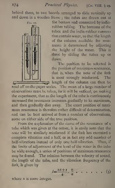
FIG. 17.
174 Practical Physics. [CH. VIII. 29.
behind them, to two boards arranged to slide vertically upand down in a wooden frame
;the tubes are drawn out at
the bottom and connected by india-
rubber tubing. The bottoms of the
tubes and the india-rubber connec-
tion contain water, so that the lengthof the column available for reso-
nance is determined by adjusting
the height of the water. This is
done by sliding the tubes up or
down.
The position to be selected is
the position of maximum resonance,
that is, when the note of the fork
is most strongly reinforced. The
;~ji length of the column can then be
read off on the paper scales. The mean of a large number of
observations must be taken, for it will be noticed, on makingthe experiment, that as the length of the tube is continuouslyincreased the resonance increases gradually to its maximum,and then gradually dies away. The exact position of maxi-
mum resonance is therefore rather difficult of determination,
and can be best arrived at from a number of observations,
some on either side of the true position.
From the explanation of the cause of the resonance of a
tube which was given at the outset, it is easily seen that the
note will be similarly reinforced if the fork has executed a
complete vibration and a half, or in fact any odd number of
half-vibrations instead of only one half-vibration. Thus, if
the limits of adjustment of the level of the water in the tube
be wide enough, a series of positions of maximum resonance
may be found. The relation between the velocity of sound,
the length of the tube, and the vibration frequency of the
fork, is given by2X+ I V
/=: (3)
where x is some integer.
Cn. VIII. 29.] Acoustics. 175
This gives a series of lengths of the resonance tube, anytwo consecutive ones differing by v\2n.
Now v\n is the wave-length in air of the note of the
fork. So that with a tube of sufficient length, a series of
positions of maximum resonance can be determined, the
difference between successive positions being half the wave-
length in air of the note of the fork.
Introducing the correction for the open end of the pipe,
the formula (3) for determining the velocity of sound be-
comes
2X+I
[The most suitable diameter of the tube for a 256 fork
is about 5 centimetres ;for higher forks the diameter should
be less.]
Experiment. Determine the lengths of the columns of air
corresponding to successive positions of maximum resonance
for the given fork and deduce the velocity of sound in air.
Enter results thus :
Vibration frequency of fork, 256 per sec.
Lengths of resonance columns :
(1) Mean of twelve observations, 31 cm.
(2) 97
Radius' of tube, 2-5 cm.
Velocity of sound, from (i) 34,340 cm. per sec.
from (2) 34,000 cm.
30. Verification of the Laws of Vibration of Strings.
Determination of the Absolute Pitch of a Note bythe Monochord.
The vibration of a string stretched between two points
depends upon the reflection at either end of the wave motion
transmitted along the string. If a succession of waves
travel along the string, each wave will in turn be reflected
at the one end and travels back along the string and be
1 76 Practical Physics. [CH. VIII, 30.
reflected again at the other end;the motion of any point of
the string is, accordingly, the resultant of the motions due
to waves travelling in both directions. Premising that a node
is a point in the string at which the resultant effect of the
incident and reflected waves is to produce no change of posi-
tion, and that a loop is a point at which the change of posi-
tion due to the same cause is a maximum, it is evident that
if a string is to remain in a state of vibration the two ends
of the string which are fixed to the supports must be nodes,
and it follows that the modes of vibration of the string must
be such that the distance between the two ends contains an
exact multiple of half the length of a wave, as transmitted
along a uniform string of indefinite length and without
obstacles.
It is shewn in works on acoustics ! that a wave of any
length travels along such a string with a velocity v where
v N/f/70, T being the stretching force of the string in dynes,
and m the mass of a unit of its length expressed in grammes
per centimetre.
If T be the time of vibration of the note, and X its wave
length in centimetres, we have, just as in the case of air,
\=VT.
If n be the vibration frequency of the note
hence _Z/__I /T~n~n\/ m'
Thtt distance / between the fixed ends of the string being an
exact multiple of -, we have2
where x is some integer.
1 See Lord Rayleigh's Sound% vol. i, chap. vi.

CH. VIII. 30.] Acoustics. 177
Whence
It is this formula whose experimental verification we pro-
ceed to describe. The apparatus usually employed for the
purpose is known as a monochord or sonometer, and con-
sists of a long wooden box with a wire, fixed at one end and
stretched between two bridges by a spring at the other, or
by means of a weight hanging down over a pulley. The
one bridge is fixed at the fixed end of the string ;the
other one is movable along a graduated scale, so that the
length of the vibrating portion of the string can be read off
at pleasure. The measurement of the stretching force T,
either by the hanging weight or by the stretching of a spring
attached to the end of the box, is rendered difficult in con-
sequence of the friction of the bridge, and therefore requires
some care. The pulley itself may be used instead of the
bridge if care be taken about the measurement of length.
For a fine brass or steel wire a stretching force equivalent to
the weight of from 10 to 20 kilogrammes may be employed.This must be expressed in dynes by the multiplication of
the number of grammes by 981.
It is convenient to have two strings stretched on the
same box, one of which can be simply tuned into unison
with the adjustable string at its maximum length by an
ordinary tuning-key, and used to give a reference note. The
tuning can be done by ear after some practice. When the
strings are accurately tuned to unison, the one vibrating
will set the other in strong vibration also; this property may
be used as a test of the accuracy of tuning. We shall call
the second the auxiliary string.
It is advisable to use metallic strings, as the pitch of the
note they give changes less from time to time than is the
case with gut strings.
Referring to the formula (i), we see that the note as
N
178 Practical Physics. [CH. VIII. 30.
there defined may be any one of a whole series, since x mayhave any integral value. We get different notes on puttingx equal to i, 2, 3 .... successively.
These notes may in fact all be sounded on the same
string at the same time, their vibration numbers being
n, 2, 3 ;/, 4 . . . . and their wave-lengths 2/, /, 2//3,
2//4 . . . respectively. The lowest of these is called
the fundamental note of the string, and the others har-
monics. These may be shewn to exist when the string
is bowed, by damping the string touching it lightly with
the finger at suitable points. Thus, to shew the existence
of the first harmonic whose wave-length is /, bow the string
at one quarter of its length from one end, and touch it
lightly at the middle point. The fundamental note will
be stopped, and the octave will be heard, thus agreeing in
pitch with the first of the series of harmonics given above.
To obtain the second harmonic bow the string about
one-sixth of its length from the end, and touch it lightly
with the finger at one-third of its length. This stops all
vibrations which have not a node at one third of the length,
and hence the lowest note heard will be the second har-
monic, which will be found to be at an interval of a fifth
from the first harmonic or of an octave and a fifth from the
fundamental tone. We may proceed in this way for any of
the series of harmonics, remembering that when the string
is damped at any point only those notes will sound that
have a node there, and on the other hand, there cannot be
a node at the place where the string is bowed; hence the
place for bowing and the place for damping must not be in
corresponding positions in different similar sections of the
wave-curve; if they were in such corresponding positions
the damping would suppress the vibration of the string alto-
gether.
The intervals here mentioned may be estimated by ear,
or compared with similar intervals sounded on the piano or
harmonium.
CH. VIII. 30.] Acoustics. 179
We shall now confine our attention to the fundamental
note of the string. Putting x=i in formula (i) we get
We have first to verify that the vibration number of the
note varies inversely as the length of the string when the
tension is constant. This may be done by sliding the
movable bridge until the note sounded is at a definite
interval from the note of the auxiliary string, with which it
was previously in unison. Suppose it to be the octave, then
the length of the adjustable string will be found to be one
half of its original length ;if a fifth, the ratio of its new
length to its original length will be 2/3, and so on;
in every
case the ratio of the present and original lengths of the
string will be the inverse ratio of the interval.
In a similar manner we may verify that the vibration
frequency varies as the square root of the tension. Byloading the scale pan hung from the pulley, until the octave
is reached, the load will be found to be increased in the
ratio of \/2 : i, and when the fifth is obtained the load will
be to the original load in the ratio of^ : ^/7.
It yet remains to verify that the vibration frequencyvaries inversely as the square root of ;;/, the mass per unit
of length of the string. For this purpose the string must be
taken off and a known length weighed. It must then be
replaced by another string of different material or thickness,
the weight of a known length of which has also been deter-
mined. Compare then the length of the two strings re-
quired to give the same note, that is, so that each is in turn
in unison with the auxiliary string. It will be found that
these lengths are inversely proportional to the square root of
the masses per unit of length, and having already provedthat the lengths are inversely proportional to the vibration
frequencies, we can infer that the vibration frequencies are
N 2
1 80 Practical Physics. [CH. VIII. 30.
inversely proportional to the square roots of the masses per
unit of length.
We can also use the monochord to determine'
the pitch
of a note, that of a fork for instance. The string has first to
be tuned, by adjusting the length, or the tension, until it is in
unison with the fork. A little practice will enable the observer
to do this, and when unison has been obtained the fork will
throw the string into strong vibration when sounded in the
neighbourhood. Care must be taken to make sure that the
fork is in unison with the fundamental note and not one
of the harmonics. The length of the string can then be
measured in centimetres, and the stretching force in dynes,
and by marking two points on the wire and weighing an
equal length of exactly similar wire, the mass per unit of
length can be determined. Then substituting in the formula
(2) we get n.
This method of determining the pitch of a fork is not
susceptible of very great accuracy in consequence of the
variation in the pitch of the note of the string, due to altera-
tions of temperature and other causes.
Experiment. Verify the laws of vibration of a string with
the given wire and determine the pitch of the given fork.
Enter results thus :
Length of wire sounding in unison with the given fork,
63-5 cm.
Stretching force (50 Ibs.), 22,680 grammes weight= 22680x981 dynes.
Mass of 25 cm. of wire, -670 grammes.Vibration frequency of fork, 256 per sec.
31. Determination of the Wave-length of a high Note in
Air by means of a Sensitive Flame, (Lord Rayleigh,Acoustical Observations, Phil. Mag.) March, 1879.)
For this experiment a note of very high pitch is re-
quired. Probably a very high organ-pipe or whistle might
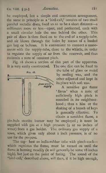
Cn. VIII. 31.] Acoustics. 181
FIG. 18.
be employed, but a simple and convenient arrangement,the same in principle as a '
bird-call,' consists of two small
parallel metallic discs, fixed so as to be a short distance a
millimetre more or less apart, and perforated, each with
a small circular hole the one behind the other. This
pair of discs is then fixed on to the end of a supply-tube,
and air blown through the holes by means of a loaded
gas bag or bellows. It is convenient to connect a mano-
meter with the supply-tube, close to the whistle, in order
to regulate the supply of air from the reservoir, and thus
maintain a note of constant pitch.
Fig. 1 8 shews a section of this part of the apparatus.
It is very easily constructed. The one disc can be fixed to
the tube of glass or metal
by sealing wax, and the
other adjusted and kept in
its place with soft wax.
A sensitive gas flame*flares
' when a note of
sufficiently high pitch is
sounded in its neighbour-hood ;
thus a hiss or the
shaking of a bunch of keysis generally effective. Toobtain a sensitive flame, a
pin-hole steatite burner may be employed ;it must be
supplied with gas at a high pressure (9 or 10 inches of
water) from a gas holder. The ordinary gas supply of a
town, which gives only about i inch pressure, is of no
use for the purpose.The tap best an india-rubber tube with pinch-cock
which regulates the flame, must be turned on until the
flame is burning steadily (itwill generally be some 18 inches
high), but just on the point of flaring. The sound of the*
bird-call,' described above, will then, if it be high enough.
1 82 Practical Physics. [CH. VIII. 31.
make the flame flare, but it will recover its steadiness whenthe sound ceases.
In order to determine the wave-length of a note by this
apparatus, a board is placed so that the sound is reflected
perpendicularly from its surface. Placing the nozzle of the
burner in the line from the source of sound perpendicularto the board, and moving the burner to and fro along this
line, a series of positions can be found in which the effect
of the sound upon the flame is a minimum.
The positions are well-defined, and their distances from
the board can be measured by taking the distances between
the board and the orifice of the burner with a pair of com-
passes, and referring them to a graduated scale. These
positions correspond to the nodal points formed by the
joint action of the incident vibration and the vibration
reflected from the surface of the board. The distance
between consecutive positions corresponds accordingly to
half a wave-length of the incident vibration. The wave-
length of the note sounded is, therefore, twice the distance
between consecutive positions of minimum effect upon the
flame.
The distances of as many successive positions as can
be accurately observed should be taken. Each observation
should be repeated three or four times and the mean taken.
Instead of the sensitive flame, an india-rubber tube lead-
ing to the ear may be employed, and positions of silence
determined. It must be remembered, however, in this case
that the position of silence for the ear corresponds to a
position of minimum pressure-variation at the orifice
of the tube that is to say, to a loop and not to a node.
The distances of these positions of silence from the wall
are, therefore, odd multiples of quarter-wave-lengths instead
of even multiples, as when the sensitive flame is used.
Experiment. Determine the wave-length of the given note
by means of a sensitive flame.
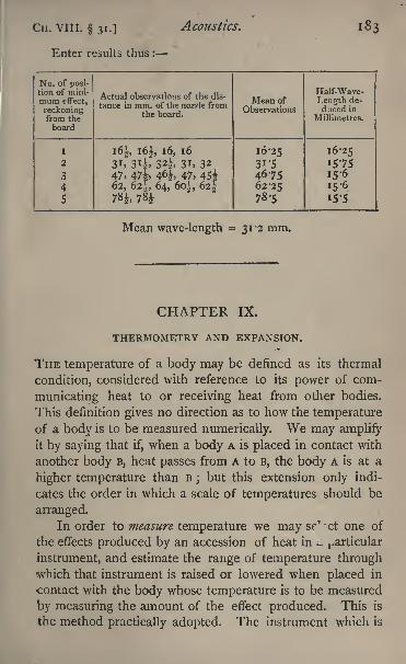
CH. VIII. 31.] Acoustics.
Enter results thus :
No. of posi-
184 Practical Physics. [Or. IX.
so used is called a thermometer, and the branch of the
science of heat which treats of the application of such in-
struments is called thermometry.A continuous accession of heat produces continuous
alteration in many of the physical properties of bodies, and
any one of them might have been selected as the basis of a
system of thermometry. Attempts, which have met with
more or less success, have been made to utilise several of
these continuous alterations for the purpose. The changeof volume of various liquids enclosed in glass vessels
;the
change in pressure of a gas when the volume is kept con-
stant, or the change in volume when the pressure is keptconstant
;the change in the electrical resistance of a wire
;
the change in the electromotive force in a thermo-electric
.circuit ; the change in length of a metallic bar ; the changein the pressure of the vapour of a liquid ; change of shapeof a spiral composed of strips of different metals, as in
Breguet's thermometer, have all been thus employed.Of all these methods of forming a system of thermo-
metry, the one first mentioned is by far the most frequently
employed. It owes its general acceptance to the fact that
the change of volume of a liquid in a glass vessel is very
easily measured with great accuracy. Moreover, if it were
not for certain slow-working changes of very small magni-tude in the volume of the glass envelope, of which we shall
speak later, the indication of such an instrument would
practically depend upon the temperature and upon nothingelse. The liquids which have been employed are mercury,
alcohol, and ether. Mercury can easily be obtained pure, and
remains a liquid, with a vapour- pressure less than the ordi-
nary atmospheric pressure for a wide range of temperatures,
including those most frequently occurring in practice. Ether
has a larger coefficient of expansion, but can only be used
for a small range of low temperatures. The thermometers
most generally in use are accordingly filled with mercury,and the expansion of mercury in a glass vessel has thus been
CH. IX.] Thermometry and Expansion. 185
adopted as the effect of heat to be employed as the basis of
the numerical measurement of temperature.
A mercury thermometer consists of a stem, a glass
tube of very fine and uniform bore, having a cylindrical or
spherical bulb blown at the end. The bulb and part of the
tube are filled with mercury, and the top of the stem is
hermetically sealed, when the bulb is so heated that the
whole instrument is filled with the liquid. When the
mercury cools and contracts the space above it is left
empty. The numerical measurement is introduced by
marking upon the stem the points reached by the mercurywhen the thermometer is maintained successively at each of
two temperatures which can be shewn to be constant, and
dividing the length of the stem between the two marks into
a certain number of equal parts. These two fixed tempera-tures are usually the temperature of melting ice, and the
temperature of steam which issues from water boiling under
a standard pressure of 760 mm. They have been experi-
mentally shewn to be constant, and can always be obtained
by simple apparatus (see 33).
The two marks referred to are called the freezing and
the boiling point respectively, and the distance between
them on the stem is divided into 100 parts for the centigrade
thermometer, and 180 for the Fahrenheit, each part beingcalled a degree.
On the former the freezing point is marked o, and on
the latter 32. The remarks which follow, when inappli-
cable to both kinds, may be held to refer to the centigradethermometer.
It should first be noticed that this system, which suppliesthe definition of the numerical measure of temperature, is
completely arbitrary. A number of degrees of temperature
corresponds to a certain percentage of the total expansionof mercury in a glass vessel between o and 100. Twoquantities of mercury will doubtless expand by the samefraction of their volume for any given range of temperature,
1 86 Practical Physics. [CH. IX.
and thus two mercury thermometers, similarly graduated,
may be expected to give identical indications at the same
temperature, provided each tube is of uniform bore, and
the expansion of the glass, as referred to the corresponding
expansion of the mercury, is uniform for each instrument.
This is in general sufficiently nearly the case for two ther-
mometers which have been very recently graduated. But a
thermometer filled with any other liquid, and agreeing with
a mercury thermometer at two points, cannot be expected to,
and does not in fact, agree with it for temperatures other
than those denoted by the two points. If it did it would
shew that the rate of expansion of its liquid in glass was
uniform for successive intervals of temperature, as defined
by the mercury thermometer, and this is generally not the
case.
Even the conditions necessary for two mercury thermo-
meters to give identical indications at the same temperatureare not, as a rule, satisfied. In the first place, the bore of
a thermometer is not generally uniform. The variation
may, indeed, be allowed for by calibration (see 8), so
that we may correct the indications for want of uniformity
of bore ; the determination of the corrections in this wayis a somewhat tedious operation. Moreover, the volume
of the glass envelope undergoes a slow secular change. Athermometer bulb, when blown and allowed to cool, goes on
contracting long after the glass has attained its normal tem-
perature, the contraction not being quite complete even
after the lapse of years. If the bulb be again heated, the
same phenomenon of slow contraction is repeated, so that,
after a thermometer is filled, the bulb gradually shrinks,
forcing the mercury higher up the tube. If the thermometer
has been already graduated, the effect of this slow contraction
will appear as a gradual rise of the freezing point.
In some thermometers the error in the freezing point
due to this cause amounts to more than half a degree,
and the error will affect the readings of all temperatures
CH. ix.] Thermometry and Expansion. 187
between o and 100 by nearly the same amount. The in-
strument should, therefore, not be graduated until some
considerable time after being filled;but even when this
precaution is taken the change in the zero point is not
completely eliminated, but only considerably diminished.
A corresponding small change of the zero point is set
up whenever the thermometer is raised to the boiling
point.
The reading of a mercury thermometer does not, there-
fore, give an indication of temperature which will be clearly
understood by persons who do not measure temperatures
by that particular thermometer. To ensure the reading
being comparable with those of other instruments, the tube
must have been calibrated, and the fixed points quite recently
re-determined, and the readings thus corrected; or, adopt-
ing another and more usual method, the individual ther-
mometer in question may be compared experimentally with
some instrument generally accepted as a standard. A set
of such are kept at the Kew Observatory ; they have
been very carefully made and calibrated, and their fixed
points are repeatedly determined, and a standard scale is
thus established. With one or more of these standards anythermometer can be compared by immersing them in water
which is kept well stirred, and taking simultaneous readingsof the two at successive intervals of temperature. In this
way a table of corrections is formed for the thermometer
which is tested, and its indications can be referred to the
Kew standard by means of the table. However, the
secular contraction of the bulb may still be going on ;but
to allow for any contraction subsequent to the Kew com-
parison, it is sufficient to ascertain if there has been any
change in the freezing point, and in that case consider that
an equal change has taken place for every temperature, and
that, therefore, each correction on the table is changed bythat amount.
A specimen table of Kew corrections is appended as an
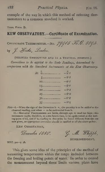
1 88 Practical Physics. [CH. IX.
example of the way in which this method of referring ther-
mometers to a common standard is worked.
THER. FORM. D.
KEW OBSERVATORY.-Certifieate of Examination.
CENTIGRADE THERMOMETER. No. J.@. 6\
(VERIFIED UNMOUNTED AND IN A VERTICAL POSITION.)
Corrections to be applied to the Scale Readings, determined by
comparison with the Standard Instruments at the Kew Observatory.
O OAt o................. -0-1
5 .................. -0-4
10 .................. 0-1
15 .................. -0-1
20 .................. -0-2
25 ............. ..... -0-2
30 .................. -0-2
35 .................. -0'4
Note I. When the sign of the Correction is +, the quantity is to be added to the
observed reading, and when to be subtracted from it.
II. Mercurial Thermometers are liable, through age, to read too high; this
instrument ought, therefore, at some future date, to be again tested at the melt-
ing point of ice, and if its reading at that point be found different from the one
now given, an appropriate correction should be applied to all the above points.
KEW OBSERVATORY,
SUPERINTENDENT.MST. 5005 78.
This gives some idea of the principles of the method of
measuring temperatures within the range included between
the freezing and boiling points of water. In order to extend
the measurement beyond these limits various plans have
CH. IX.] Thermometry and Expansion. 189
been adopted. The mercury thermometer is sometimes
used, its stem beyond the limits being divided into degrees
equal in length to those within the limits. A thermometer
divided in this way can be used for temperatures down to
40, and up to 350 C. ; but, unfortunately, the difference
in the expansion of different specimens of glass is such that
at the higher temperatures two thermometers, similarly gra-
duated, may differ by as much as ten degrees, and hence the
mercury thermometer thus used does not give a satisfactory
standard. Two air thermometers, on the other hand, when
properly corrected for the expansion of the glass, always
give the same readings, and thus the air thermometer has
come to be recognised as the temperature standard for high
and low temperatures. It is referred to the mercury standard
for the freezing and boiling points and intermediate tem-
peratures; thus the higher temperatures are expressed in
centigrade degrees by a species of extrapolation, using the
formula for the expansion of a permanent gas as deter-
mined by observations within the limits of the mercurythermometric standard.
Other methods of extrapolation from a formula verified
by comparison, either with the mercury or air thermometer,have sometimes been employed with more or less success,
in order to determine temperatures so high that the air
thermometer is unsuitable, such as, for instance, the tem-
perature of a furnace. In the case of Siemens' resistance
pyrometer, a formula is obtained by experiments at low
temperatures, expressing the relation between the resistance
of a platinum wire and its temperature ;the temperature of
the furnace is then deduced from an observation of the
resistance of the platinum on the supposition that the
formula holds, although the temperature is a long way out-
side the limits of verification. The temperature obtained
in some manner, generally analogous to this, is often ex-
pressed as so many degrees centigrade or Fahrenheit. It
is evident that numbers obtained by different methods may
190 Practical Physics. [CHAP. IX.
be widely different, as all are arbitrary. At present it is a
matter of congratulation if two different instruments on the
same principle give comparable results ; and, until somemore scientific, or rather, less arbitrary, method of measuring
temperatures is introduced, the precise numbers quoted for
such temperatures as those of melting silver or platinum must
remain understood only with reference to the particular
system of extrapolation adopted to extend the range of
numbers from those properly included in the range of the
mercury thermometer, namely, those between the freezing
and boiling points of water.
32. Construction of a Water Thermometer.
The method of filling a thermometer is given in full in
Garnett's 'Heat,' 10-18, also in Deschanel's 1 or Ganot's' Natural Philosophy,' and Maxwell's ' Heat/
In this case water is to be used instead of mercury.One or two points may be noticed :
(1) The tube and bulb have not always a cup at the
top as in Garnett (fig. i).When this is the case, a piece of
wide glass tubing must be drawn out to serve as a funnel,
and joined by means of clean india-rubber to the tube of
the thermometer.
(2) It would be difficult to seal the glass tube when full
of water, unless it has been previously prepared for closing.
After the bulb has been filled, but before it is again heated
to the high temperature, the upper part of the tube is
softened in a blow-pipe flame, and drawn out so as to leave
a fine neck in the tube. Then the bulb is heated until the
liquid rises above this neck, and when this is the case the
tube is sealed by applying a small blow-pipe flame at the
thinnest part.
At the moment of sealing the source of heat must be
removed from the bulb, otherwise the liquid will continue
to expand, owing to the rise of temperature, and will burst
1
Deschanel, Natural Philosophy, p. 245, etc.
CH. IX. 32.] Thermometry and Expansion. 191
the bulb. The safest way of heating the bulb is to put it in
a bath of liquid melted paraffin, for example, or water if the
thermometer be not required for use near the boiling point
and apply heat to the bath until the liquid in the thermo-
meter reaches beyond the neck. Remove the source of heat
from the bath and seal off the tube as the level of the water
sinks past the narrow neck.
(3) The water used for filling the thermometer should be
distilled water from which the dissolved air has been driven
by long-continued boiling. This precaution is essential, as
otherwise bubbles of air separate from the water in the bulb
and stem after sealing, and this often renders the thermometer
useless until it has been unsealed and the air removed and
the tube re-sealed,
We proceed to shew how to use the thermometer to de-
termine the coefficient of expansion of the water.
We require, for this purpose, to know the volume of any
given length of the tube and the whole volume of water con-
tained in the thermometer.
Tofind the Volume of any Length of the Tube.
Before filling the thermometer, introduce into the tube a
small pellet of mercury and measure its length, which should
be from 10 to 20 cm. Then warm the bulb and force the
mercury out into a beaker, of which the weight is known.
Weigh the beaker and mercury, and get by subtraction
the weight of the mercury. Now, we may take the density of
mercury to be 13*6. If, then, we divide the mass in grammesby this number, we get the volume in cubic centimetres.
We thus find the volume of a known length that of the
pellet of mercury of the tube, and from this can determine
the volume of any required length. For greater accuracy it
is necessary to measure the length of the same pellet of
mercury at different parts of the tube, thus calibrating the
tube (see 8).
To find the Volume of the Water which is contained in the
TJiermometer.
Weigh the bulb and tube when empty, then weigh it again
IQ2 Practical Physics. [CH. IX. 32.
when filled, before sealing off. The difference in the weights
gives the number of grammes of water in the bulb and tube,
and hence the number of cubic centimetres of water in the
two can be calculated.
It may be more convenient to seal off before weighing,but in this case great care must be taken not to lose any of
the glass in the act of sealing, and to put the piece of glass
which is drawn off on the balance with the tube.
If the thermometer be filled with some other liquid than
water, we obtain the volume from the mass by dividing
by the density of the liquid.
Let us suppose the volume of i cm. length of the tube
is *oi c.c., and that the volume of the water contained
is 4*487 c.c.
After sealing the tube as already described, immerse it
in a bath of water at the temperature of the room, noting
that temperature by means of a thermometer; suppose it to
be 15 C.
Make a mark on the tube at a known distance above
the level of the water in it let us say at 10 cm.
Now raise the temperature of the bath until the level of
the water in the tube rises to this mark, and then note the
temperature as indicated by the other thermometer. Weshall find that with the numbers given it will be about 70 C.
The water has risen 10 cm., and the volume of i cm. is
*oi c.c. Thus the volume of water has been increased
relatively to the glass by -i c.c.
The original volume was . . 4*487 c.c.
The new volume is . . . 4-587 c.c.
The rise of temperature is 70 15, or 55 C.
Thus the coefficient of expansion of water relatively to
the glass between these temperatures is -^ per4-487x55
degree centigrade.
This, on reduction, comes to -000405.
The coefficient of expansion of water varies considerably
CH, IX. 32.] Thermometry and Expansion. 193
with the temperature, so that the result will be the mean co-
efficient between the limits of temperature 15 and 70.
Experiment. Determine by means of a water thermometer
the coefficient of thermal expansion of water.
Enter results thus :
Length of pellet of mercury 15-3 cm.
Weight of do. 2-082 gm.Vol. of i cm. of tube *oi c.c.
Vol. water initially 4-487 c.c. Temp. 15
Vol. finally 4-587 c.c. Temp. 70Coeff. of expansion = '000405 per i.
33. Thermometer Testing.
By this we mean determining the indications of the
thermometer which correspond to the freezing point of
water and to its boiling point under a pressure of
760 mm.The first observation is made by placing the thermo-
meter so that its bulb and stem up to the zero are sur-
rounded with pounded ice. The ice must be very finely
pounded and well washed to make quite sure that there is
no trace of salt mixed with it. This precaution is very im-
portant, as it is not unusual to find a certain amount of salt
with the ice, and a very small amount will considerably re-
duce the temperature.The ice should be contained in a copper or glass funnel
in order that the water may run off as it forms. The ther-
mometer should be supported in a clip, lest when the ice
melts it should fall and break.
The boiling point at the atmospheric pressure for the
time being may be determined by means of the hypsometer,an instrument described in any book on physics.
1
The thermometer to be tested must be passed throughthe cork at the top of the hypsometer, and there fixed
1
Garnett, ffeaf, 12, &c. Deschanel, Natural Philosophy\p. 248, &c.
O
194 Practical Physics. [CH. IX. 33.
so that the 100 graduation is just above the cork. Oneaperture at the bottom of the cover of the hypsometer is
to allow the steam issuing from the boiling water to es-
cape ;to the other aperture is attached by an india-rubber
tube a pressure gauge, which consists of a U-shaped glass
cube containing some coloured liquid. The object of this
is to make sure that the pressure of the steam within the
hypsometer is not greater than the atmospheric pressure.
The water in the hypsometer must be made to boil
and the thermometer kept in the steam until its indication
becomes stationary. The temperature is then read.
In each of these operations, in order to make certain
of avoiding an error of parallax in reading (i.e. an error
due to the fact that since the object to be read and the scale
on which to read it are in different planes, the reading will
be somewhat different according as the eye looks perpen-
dicularly on the stem or not), the thermometer must be
read by a telescope placed so that it is at the same heightas the graduation to be read. If, then, the thermometer be
vertical, the line of sight being horizontal will be perpen-dicular to it. (It must be remembered in estimating a
fraction of a division of the thermometer that in the telescopethe image of the scale is inverted.)
We thus determine the boiling point at the atmospheric
pressure for the time being. We have still to correct for the
difference between that pressure and the standard pressureof 760 mm. To do this the height of the barometer must
be read and expressed in millimetres. We obtain from a
table shewing the boiling point for different pressures, the
fact that the difference in the temperature of the boiling
point of i corresponds to a difference of pressure of 26-8
mm. We can, therefore, calculate the effect of the difference
of pressure in our case.
Suppose the observed boiling point reading is 99*5, andthe height of the barometer 752 mm. We may assume that,
for small differences of pressure from the c< '
'?.- 1 *"
^re,
Cn. IX. 33.] Thermometry and Expansion. 195
the difference in the boiling point is proportional to the
difference of pressure ;hence
760 752 __ required correctionm
26-8~
~~^~qo
.'. the required correction = _ - = '3.2O'O
And therefore the corrected boiling point would read
99 '8 on the thermometer.
The correction is to be added to the apparent boiling-
point reading if the atmospheric pressure is below the
standard, and vice versa.
Experiments.
(1) Determine the freezing and boiling points of the giventhermometer.
Enter results thus :
Thermometer, Hicks, No. 14459.
Freezing point -o-i.
Boiling point 99'8.
The following additional experiments may be performedwith the hypsometer.
(2) Put some salt into the hypsometer and observe the
boiling point again.
(3) Tie some cotton wick round the bulb of the thermometer,and let the end drop into the solution. Vide Garnett, 13.
(The cotton wick should be freed from grease by beingboiled in a very dilute solution of caustic potash and well
washed.)
(4) Remove the water, clean the thermometer, and repeatthe observation with a given liquid.
Boiling point of alcohol is 79.ether 37.
turpentine 130.
(5) Clean the thermometer and hypsometer, and remove
the apparatus to a room in the basement, and observe the tem-
perature of the boiling point of water.
Take the apparatus up to the top of the building and repeat,
o 2
1 96 Practical Physics. [CH. IX. 33.
and from the two observations determine the height of the
building thus :
The difference of temperature of the two boiling points
depends only on the difference of pressure. Also an increase
of pressure of i mm. of mercury produces an alteration of
the temperature of the boiling point of 0-0373 C., or an
increase of temperature of the boiling point of i correspondsto a pressure of 26-8 mm. of mercury.
Now the specific gravity of mercury referred to water is
13-6, that of dry air at 760 mm. pressure, and 15 C.
temperature is '001225. Thus the pressure due to i mm.
of mercury is equal to that due to -^ mm., or ino2001225
metres of dry air.
But a rise in temperature of i corresponds to an increase
in pressure of 26^8 mm. mercury ; that is, to an increase of
pressure due to 1 1 '102 x 26*8 metres of dry air.
Thus, the boiling point alters by i C. for an alteration
of pressure equal to that due to a column of dry air at 15 C.
and of 297-5 metres in height.
34. Boiling Point of a Liquid,
A liquid is usually said to boil at a temperature t whenthe pressure of its vapour at this temperature is equal to
the external pressure/. But if the sides of the vessel be
smooth and the liquid be quite free from dissolved air, or if it
contain salts in solution, it will generally not boil till its
temperature is higher than /.
Suppose the liquid to boil at / + T, then the vapour
rising up at this temperature will exert a pressure greater
than the external pressure /. Consequently it will expandtill its pressure falls to /, its temperature at the same time
falling till it reaches the corresponding temperature t.1
Hence the temperature of the vapour over a boiling liquid
under a given pressure /, is a constant quantity under all
1
Maxwell, Heat, pp. 25 and 289.
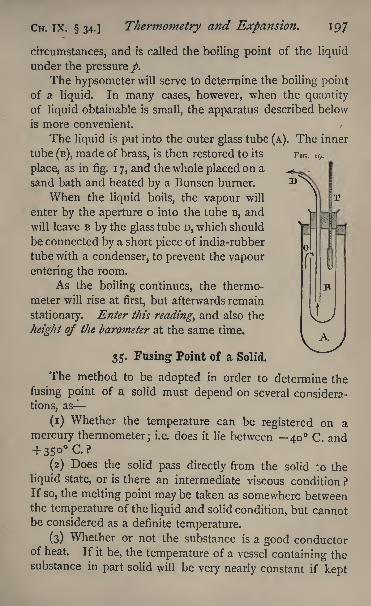
CH. IX. 34.] Thermometry and Expansion. 197
circumstances, and is called the boiling point of the liquid
under the pressure/.The hypsometer will serve to determine the boiling point
of a liquid. In many cases, however, when the quantity
of liquid obtainable is small, the apparatus described below
is more convenient.
The liquid is put into the outer glass tube (A). The inner
tube (B), made of brass, is then restored to its FIG. i9 .
place, as in fig.1 7, and the whole placed on a
sand bath and heated by a Bunsen burner.
When the liquid boils, the vapour will
enter by the aperture o into the tube B, and
will leave B by the glass tube D, which should
be connected by a short piece of india-rubber
tube with a condenser, to prevent the vapour
entering the room.
As the boiling continues, the thermo-
meter will rise at first, but afterwards remain
stationary. Enter this reading, and also the
height of the barometer at the same time.
35. Fusing Point of a Solid.
The method to be adopted in order to determine the
fusing point of a solid must depend on several considera-
tions, as
(i) Whether the temperature can be registered on a
mercury thermometer; i.e. does it lie between 40 C and
(2) Does the solid pass directly from the solid to the
liquid state, or is there an intermediate viscous condition ?
If so, the melting point may be taken as somewhere betweenthe temperature of the liquid and solid condition, but cannotbe considered as a definite temperature.
(3) Whether or not the substance is a good conductorof heat. If it be, the temperature of a vessel containing thesubstance in part solid will be very nearly constant if kept
198 Practical Physics. [CH. IX. 35.
properly stirred. This is the case with ice and the fusible
metals and alloys. For bodies which are bad conductors a
method has to be adopted as occasion requires. We give
as an instance the following, which is available in the case of
paraffin wax.
The thermometer, when dipped into the- melted paraffin,
is wetted by the liquid, and when taken out is in con-
sequence covered with a very thin and perfectly transparent
film of liquid paraffin. This film cools, and on solidifying
assumes a frosted appearance which extends rapidly all over
the part of the thermometer that has been immersed. If
the bulb of the thermometer is sufficiently small for us to
neglect the difference of temperature between the interior
and exterior portions of the mercury, the observation of the
thermometer at the instant when this frosted appearancecomes over the bulb may be taken as the melting point of
paraffin. The only error likely to be introduced is that
mentioned above, viz. that the temperature of the paraffin is
not the mean temperature of the thermometer bulb. This
can be rendered smaller and smaller by taking the liquid at
temperatures approaching more and more nearly to the
melting point as thus determined, and its direction can be
reversed if we allow the paraffin to solidify on the bulb and
then heat the bulb in a beaker of water and note the tem-
perature at the instant when the film becomes transparent.
The mean of this temperature and that deduced from the
previous experiment will be the melting point.
COEFFICIENTS OF EXPANSION.
Definition. A coefficient of expansion by heat may be
defined as the ratio of the change of a volume, area, or
length per degree of temperature to the value of that volume,
area, or length at zero centigrade.
In solids and liquids the expansion is so small that in
practice we may generally use, instead of the value of the
quantity at zero, its value at the lower of the two tempera-tures observed in the experiment.
CH. IX.] Thermometry and Expansion. 199
For solid bodies we have the coefficients of linear, super-
ficial, and cubical expansion depending on the alteration of
length, breadth, or thickness (linear), of surface (superficial),
and of volume (cubical) respectively.
Let a, /?, y be these three respectively, and suppose the
body to be isofropic, i.e. to have similar properties in all
directions round any given point ;then it can be shewn
that/? 20, y=3a.1
For liquid bodies we have to deal only with the coefficient
of cubical expansion.
Any measurement of expansion is attended with con-
siderable difficulty.
A liquid requires to be contained in some vessel, and thus
we have to consider the alteration in volume of the vessel
as well as that of the liquid itself. In the case of a solid,
any cause which changes the temperature of the body to
be measured probably changes that of the measuring appa-ratus and causes it to expand also. Our measurements will
therefore give the expansion of one substance relatively to
another. Thus, we should find, mercury and most liquids
expand considerably as compared with glass, while the
metals expand greatly in comparison with wood or stone.
Methods, it is true, have been devised for determiningthe absolute expansion either of a liquid or a solid, but
tl ese are'too complicated for an elementary course.
We shall explain how to determine (i) by means of read-
ing microscopes, the coefficient of linear expansion of anysolid which can be obtained in the form of a long rod, and
(2), by means of the weight thermometer, the coefficient of
expansion of a liquid and also that of cubical expansion of
a solid.
In the case of a gas we may consider either the altera-
tion of volume under constant pressure or the alteration of
pressure at constant volume. We shall describe an experi-
mental method of measuring the latter of these two.
* Qarnett, Heat, 77. Deschanel, Natural Philosophy, p. 265.
2OO Practical Physics. [CH. IX. 36,
36. Coefficient of Linear Expansion of a Eod.
We require to measure the length of a rod, or the dis-
tance between two marks on it, at two known temperatures,
say 15 C. and 100 C.
The highest degree of accuracy requires complicated
apparatus. The following method is simple, and will give
very fair results.
A thick straight rod is taken, about 50 cm. in length,
and a glass tube of 4 or 5 cm. bore and somewhat greater
length than the rod. The tube is closed with a cork at
each end, and through each cork a small piece of glass tubingis passed, and also a thermometer. Two fine scratches are
made on the rod, one close to each end, at right angles to
its length, and two other scratches, one across each of the
former, parallel to the length. The glass tube is clampedin a horizontal position and the rod placed inside it, resting
on two pieces of cork or wood in such a manner that the
scratches are on the upper surface and can be seen throughthe glass. The whole should rest on a large stone slab
a stone window-sill serves admirably.The piece of glass tubing in one of the corks is connected
with a boiler from which steam can be passed into the tube,
the other communicates with an arrangement for condensingthe waste steam.
A pair of reading microscopes are then brought to view
the cross-marks on the rod, and are clamped securely to the
stone. The microscopes, described in 5, should be placedso that they slide parallel to the length of the rod
;this can
be done by eye with sufficient accuracy for the purpose.
If microscopes mounted as in 5 are not available, a
pair with micrometer eye-pieces, or with micrometer scales
in the eye-pieces, may be used.
For convenience of focussing on the rod which is in the
glass tube, the microscopes must not be of too high a power.
Their supports should be clamped down to the stone at
CH. ex.. 36.] Thermometry and Expansion. 201
points directly behind or in front of the position of the
microscopes themselves, to avoid the error due to the ex-
pansion of the metal slides of the microscopes, owing to
change of temperature during the experiment.
Call the microscopes A and B;
let A be the left-hand one
of the two, and suppose the scale reads from left to right.
Turn each microscope-tube round its axis until one of the
cross-wires in the eye-piece is at right angles to the length
of the rod, and set the microscope by means of the. screw
until this cross-wire passes through the centre of the cross
on the rod.
Read the temperature, and the scale and screw-head of
each microscope, repeating several times. Let the meanresult of the readings be
Temp. A B
15 C . . , 5*106 cm. 4738 cm.
Now allow the steam to pass through for some time ;
the marks on the copper rod will appear to move under the
microscopes, and after a time will come to rest again.
Follow them with the cross-wires of the microscopes and
read again. Let the mean of the readings be
Temp. A B100 C. . . . 5*074 cm. 4*780 cm.
Then the length of the rod has apparently increased by
5*106- 5'o74+ 4'78o 4-738, or -074 cm.
The steam will condense on the glass of the tube which
surrounds the rod, and a drop may form just over the cross
and hide it from view. If this be the case, heat from a small
spirit flame or Bunsen burner must be applied to the glassin the neighbourhood of the drop, thus raising the tempera-ture loc My and causing evaporation there.
Of course the heating of the rod and tube producessome alteration in the temperature of the stone slab andcauses it to expand slightly, thus producing error. This will
be very slight, and for our purpose negligible, for the rise of
2O2 Practical Physics. [CH. IX. 36.
temperature will be small and the coefficient of expansionof the stone is also small.
We have thus obtained the increase of length of the rod
due to the rise of temperature of 85. We require also its
original length.
To find this, remove the rod and tube and replace them
by a scale of centimetres, bringing it into focus. Bring the
cross-wires over two divisions of the scale, say 10 and 60,
and let the readings be
A B
4*576 cm. 5'2I 3 cm -
Then clearly the length of the rod at 15 is
5o-(5'io6 -4-576) + (4-738-5-213),or
48^995 cm.
To find the coefficient of expansion we require to knowthe length at o C.
;this will differ so little from the above
that we may use either with all the accuracy we need, and
the required coefficient is- -,or -0000178.
85x48-995'
Experiment. Determine the coefficient of expansion of the
given rod.
Enter results thus :
Increase of length of rod between 15 and 100 "074 cm.
Length at 15 , , . . . . , 48-995 cm.
Coefficient ....... -0000178
37. The Weight Thermometer.
The weight thermometer,1 consists of a glass tube closed
at one end, drawn out to a fine neck, which is bent so that
it can easily dip into a vessel of liquid.
It is used (i) to determine the coefficient of expansion of
a liquid relatively to glass ; (2) to determine the coefficient
of expansion of a solid, that of the liquid being known.1
Garnett, Heat, 80, 84. Deschanel, Natural Philosophy, p. 283.
CH. IX. 37. J Thermometry and Expansion. 203
For (i) we first fill the thermometer with the liquid
and determine the weight of liquid inside, when the whole
is at some known low temperature, e.g. that of the room
or that of melting ice. We then raise the thermometer and
liquid to some higher temperature, that of boiling water, sup-
pose. Part of the liquid escapes from the open end. The
weight of that which remains inside is then determined, and
from these two weights, and the known difference between
the temperatures at which they respectively fill the thermo-
meter, we can calculate the coefficient of expansion of the
liquid relatively to the glass.
Our first operation will be to weigh the empty glass
tube, which must be perfectly clean and dry. Let its weightbe 5*621 grammes.
We now require to fill it.
For this purpose it is heated gently in a Bunsen burner
or spirit lamp, being held during the operation in a test-tube
holder. Its neck is then dipped under the surface of the
liquid whose coefficient of expansion is required glycerine,
suppose and the tube allowed to cool. The pressure of
the external air forces some of the glycerine into the tube.
As soon as the liquid ceases to run in, the operation is
repeated, and so on until the tube is nearly full. It is then
held with its orifice under the glycerine, and heated until
the fluid in the tube boils. The air which remained in is
carried out with the glycerine vapour and the tube left filled
with hot glycerine and its vapour.The flame is removed and the thermometer again cooled
down, when the vapour inside condenses and more liquid
is forced in by the external air pressure. If a bubble of air
is still left inside, the operation of heating and cooling must
be repeated until the bubble is sufficiently small to be gotrid of by tilting the thermometer so that it floats up into the
neck.
There is another plan which may sometimes be adoptedwith advantage for partially filling the thermometer.
204 Practical Physics. [CH. IX. 37.
Place it, with its beak dipping into the glycerine, under
the receiver of an air-pump and exhaust. The air is drawn
both out of the thermometer and the receiver. Re-admit
the air into the receiver. Its pressure on the surface of the
glycerine forces the liquid into the tube. It is difficult,
however, by this method to get rid of the last trace of air.
Suppose the thermometer is filled; it is now probably
considerably hotter than the rest of the room. Hold it
with its beak still below the surface of the glycerine and
bring up to it a beaker of cold water, so as to surround
with water the body of the tube and as much as possible of
the neck. This of course must not be done too suddenlylest the glass should crack.
Let the thermometer rest in the beaker of water its
orifice still being below the surface of the glycerine and stir
the water about, noting its temperature with an ordinarythermometer.
At first the temperature of the water may rise a little;
after a time it will become steady, and the tube may be
removed. Let the observed temperature be 15 C. Wehave now got the weight thermometer filled with glycerine
at a temperature of 15 C.
Weigh the tube and glycerine ; let the weight be 16*843
grammes. The weight of glycerine inside then is 16*843
5*621, or 11*222 grammes.It is advisable to arrange some clamps and supports to
hold the tube conveniently while it is cooling in the beaker
of water.
Instead of using water and cooling the thermometer to
its temperature, we may use ice and cool it down to a tem-
perature of o C. If we do this we must, as soon as the
tube is taken out of the ice, place it inside a small beaker
of which we know the weight, for the temperature will at
once begin to rise and some of the glycerine will be driven
out. Thus we should lose some of the liquid before wecould complete the weighing.
CH. IX. 37.] Thermometry and Expansion. 205
Our next operation is to find the weight of liquid
which the tube will hold at 100 C. To do this we place
it in a beaker of boiling water, setting at the same time a
receptacle to catch the glycerine which is forced out.
When the water has been boiling freely for some time take
out the tube, let it cool, and then weigh it Subtracting the
weight of the glass, let the weight of the glycerine be 10765
grammes.Thus 10765 grammes of glycerine at 100 C. apparently
occupy the same volume that of the thermometer as
11-222 grammes did at 15 C.
The apparent expansion for an increase of temperatureof 85 (from 15 100) is therefore '0425. The mean
apparent expansion per i C. throughout that range is,
therefore,'
or -00050.
This is only the coefficient of expansion relatively to
glass, for the glass bulb expands and occupies a greater
volume at 100 C. than at 15 C.
To find the true coefficient of expansion we must re-
member that the apparent coefficient is the true coefficient
diminished by that of the glass had the glass at 100 been
of the same volume as at 15 more glycerine would have
been expelled. The coefficient of expansion of glass maybetaken as -000026. Thus the true coefficient of expansionof the glycerine is -000526.
To obtain the temperature when we take the tube from
the bath of boiling water, we may use a thermometer, or,
remembering that water boils at 100 C. for a barometric
pressure of 760 mm. of mercury, while an increasing pressure
of 26-8 mm. of mercury raises the boiling point by i C.,
we may deduce the temperature of the boiling water from
a knowledge of the barometric pressure.
It is better, if possible, to raise the temperature of the
weight thermometer to the boiling point by immersing it in
2o6 Practical Physics. [Cn. IX. 37.
the steam rising from boiling water, as in the hypsometer. Asuitable arrangement is not difficult to make if the labora-
tory can furnish a hypsometer somewhat wider than the usual
ones, with a good wide opening in the top of the cover.
(2) To obtain the coefficient of expansion of a piece of
metal iron, for example relatively to glycerine, we take a
bar of the metal whose volume is obtained from a know-
ledge of its weight and specific gravity, and place it in the
tube before the neck is drawn out.
The bar should be bent so as only to touch the tube at
a few points, otherwise it will be impossible to fill the tube
wiih the glycerine.
The tube is filled after having been weighed when
empty, and the weight of glycerine in it at a known tem-
perature is determined. Let the temperature be o C. It is
then raised to say 100 C. and the weight of the glycerine
within again determined. The difference between these
two gives the weight of glycerine expelled.
Let us suppose we know the specific gravity of glycerine;
we can obtain the volume of the glycerine originally in the
tube by dividing its weight by its density. Let us call
this Vj. We can also find the volume of the glycerine ex-
pelled ;let this be v, and let v2 be the volume of the iron,
at the lower temperature, v, the volume of the thermometer,
/, the change in temperature, a, the coefficient of expansionof the glycerine, /?, the coefficient of expansion of the metal,
y, the coefficient of expansion of the glass.
Then v=V!+v 2 .
When the temperature has risen / the volume of gly-
cerine is v^i + a/) and that of the metal is V2(i +fi t) ;
thus
the whole volume of glycerine and iron will be v^i +a/) +V 2 (i +fi t).
The volume of the glass is v(i +7 /).
The difference between these must clearly give the
volume of glycerine which has escaped, or v.
Thus v^i+o^+v^i -f-/3/)-v
But v=V!+v2 .
Thus v^a-y) /+ V 203--y}t=v.
Cn. IX. 37.] TJiennoiuctry and Expansion. 207
Vj(a y)/is the volume of glycerine which would have
been expelled if the volume of the tube had been Y! ;that
is to say, if the tube had been such as to be filled entirely
with the glycerine which was contained in it at the first
weighing. This can be calculated from the knowledge of the
weight and specific gravity of the glycerine and of the value
of the coefficient of expansion of the glycerine relatively to
the glass. Subtract this from the volume actually expelled.
The difference is the increase in volume of the metal rela-
tively to glass for the rise in temperature in question. Divide
the result by the volume of the metal and the rise in tem-
perature ;we get the coefficient of relative expansion of the
metal.
Thus, let the original weight of glycerine be 11-222 gins.,
then the amount which would be expelled, due to the rise
of temperature of the glycerine only, will be '457 gramme,since the coefficient of expansion of glycerine relative to
glass is -0005. Suppose that we find that -513 gramme is
expelled. The difference, -056 gramme, is due to the ex-
pansion of the metal. Taking the specific gravity of glycerineas 1-30, the volume of this would be -043 c.c. Supposethat the original volume of the metal was 5 c.c. and the rise
of temperature 100 C., the coefficient of expansion is given
by dividing -043 by 500, and is, therefore, -000086.
Experiments. Determine the coefficient of expansion of the
given liquid and of cubical expansion of the given solid.
Enter results thus :
Weight of empty tube .... 5'o6gms.Weight of tube full at 1 5- 5 . . . 11-58
5) 100 -6 . . . 11-32
Weight of liquid at 15-5 .... 6-52
Weight expelled -26
Coefficient of expansion relative to glass . -000488of glass . . -000026
True coefficient of expansion , . . -0005 14
Similarly for the second experiment.
208 Practical Physics. [CH, IX. 38.
38. The Air Thermometer. Determination of the Co-
efficient of Increase of Pressure of a Gas at constant
Volume per Degree of Temperature.
The air is contained in a closed flask or bulb, which canbe heated to any required temperature. From this a tube,
after being bent twice at right angles, passes vertically down-wards to a reservoir of mercury, into one end of which a
plunger is fitted. A second and longer vertical tube is
also screwed into this reservoir. On the tube connectingthe bulb with the reservoir is a mark, which should be as
near the bulb as it can conveniently be.
By means of the plunger the level of the mercury in this
tube is adjusted until it coincides with the mark, the bulb
being kept at o C. by immersion in melting ice. The
mercury at the same time moves in the other tube, and the
difference of level of the two columns is measured by meansof the kathetometer or of scales placed behind the tubes.
Let this difference be 5-62 cm., and, suppose the heightof the barometer to be 75*38 cm., then the pressure on the
enclosed gas is that due to a column of mercury 81 cm. in
height.
It is of the greatest importance that the air in the bulb
should be free from moisture. The bulb must, therefore,
have been thoroughly dried and filled with dry air by the use
of the three-way cock, drying tubes, and air-pump, as already
described, ( 16). In Jolly's air-thermometer the three-waycock is permanently attached to the tube which connects
the bulb with the reservoir.
The bulb is next immersed in a vessel of water which
is made to boil, or, better still, in the steam from boiling
water. The mercury is thus forced down the tube con-
nected with the bulb, but by means of the plunger it is
forced back until it is level again with the mark. At the
same time it rises considerably in the other tube. Whenthe water boils and the conditions have become steady, the
CH. ix. 38.] Thermometry and Expansion. 209
difference of level in the two tubes is again noted. Supposewe find it to be 34^92 cm., and that the barometer has re-
mained unchanged.The air is now under a pressure due to 110*3 cm. of
mercury, its volume remaining the same. The increase of
pressure, therefore, is that due to 29-3 cm., and the coefficient
of increase per degree centigrade is
293,or -00362.
81 x 100
In this case it is important that the lower temperatureshould be o C., for to determine the coefficient we have to
divide by the pressure at o C., and the difference between
this and the pressure at the temperature of the room, say
15, is too great to be neglected, as in the case of a solid or
liquid.
If greater accuracy be required, allowance must be madefor the expansion of the glass envelope, and for that portion
of the air in the connecting tube which is not at the tem-
perature of the bath.
The same apparatus can be used to determine the coeffi-
cient of increase of volume at constant pressure per degreeof temperature.
In this case make the first observation as before, notingat the same time the height at which the mercury stands
in the marked tube. Now heat the bulb. The air will
expand and drive the mercury down the one tube and upthe other, thus increasing at the same time the volume of
the air and the pressure to which it is subject. By with-
drawing the plunger the mercury is allowed to sink in both
tubes. It must, however, sink faster in the one open to the
external air, and after a time a condition will be reached
in which the difference between the levels in the two is the
same as it was originally. The air in the bulb is under the
same pressure as previously, but its temperature has been
raised to 100 C. and its volume altered. Observe the level
of the mercury in the tube connected with the bulb. If
p
2io Practical Physics. [CH. IX. 38.
the bore of this tube be known, the change of level will
give the increase of volume; hence, knowing the original
volume, the coefficient of expansion per degree of tempe-rature can be found.
Owing to the large amount of expansion produced in a
gas by a rise of temperature of 100 C, a tube of large bore
is required.
The method, however, as here described will not lead to
very accurate results, for it is almost impossible to insure
that the air in the bulb and that in the tube should be all
at the same high temperature. In the first method, on the
other hand, the portion of tube occupied by air can be
made very small, so as easily to be jacketed along with the
bulb and kept at an uniform high temperature.
The method is open to the objection that the air in
contact with the mercury, and therefore the mercury itself,
is at a different temperature in the two parts of the experi-
ment. The density of the mercury, therefore, is different
and the increment of pressure is not strictly proportional to
the difference of level. This error will be but small.
We have described the experiment as if air was the gas
experimented with. Any other gas which does not attack
the mercury may be used.
Experiment. Determine for the given gas the coefficient of
the increase of pressure per degree of temperature at constant
volume.
Enter results thus :
Temperature Difference of level
of gas of mercury
o C . 5-62 cm.
100 C 34-92 cm.
Barometer . . . . 75-38 cm.
Coefficient of expansion . . -00362
CH. x.] Calorimetry. 211
CHAPTER X.
CALORIMETRY.
BY Calorimetry we mean the measurement of quantities of
heat. There are three different units of heat which are em-
ployed to express the results : (i) the amount of heat re-
quired to raise the temperature of unit mass of water from
oC. to iC. ; (2) the amount of heat required to melt unit
mass of ice; (3) the amount of heat required to convert unit
mass of water at 100 into steam at the same temperature.
Experiments will be detailed below ( 39) by which the
last two units may be expressed in terms of the first,
which is generally regarded as the normal standard. Calo-
rimetric measurements are deduced generally from one of
the following observations : (i) the range of temperature
through which a known quantity of water is raised, (2) the
quantity of ice melted, (3) the quantity of water evaporatedor condensed ; or from combinations of these. The results
obtained from the first observation are usually expressed in
terms of the normal unit on the assumption that the quantity
of heat required to raise a quantity of water through one
degree is the same, whatever be the position of the degreein the thermometric scale. This assumption is very nearly
justified by experiment. As a matter of fact, the quantity
of heat required to raise unit mass of water from 99C. to
iooC. is i -oi 6 normal units.
The results of the second and third observations men-
tioned above give the quantities of heat directly in terms of
the second and third units respectively, and may therefore
be expressed in terms of normal units when the relations
between the various units have once been established.
p 2
212 Practical Physics. [CH. X. 39-
39. The Method of Mixture.
Specific Heat.
In this method a known mass of the material of which
the specific heat is required is heated to a known tempera-
ture, and then immersed in a known mass of water also at a
known temperature. A delicate thermometer is immersedin the water, and the rise of temperature produced by the
hot body is thereby noted. The quantity of heat requiredto produce a rise of temperature of i in the calorimeter
itself, with the stirrer and thermometer, is ascertained by a
preliminary experiment. We can now find an expressionfor the quantity of heat which has been given up by the
hot body, and this expression will involve the specific heat
of the body. This heat has raised the temperature of a
known mass of water, together with the calorimeter, stirrer,
and thermometer, through a known number of degrees, and
another expression for its value can therefore be found,
which will involve only known quantities. Equating these
two expressions for the same quantity of heat, we can deter-
mine the specific heat of the material. Let M be the mass
of the hot body, T jts temperature, and c its specific heat;
let m be the mass of the water, / its temperature initially,
and be the common temperature of the water and bodyafter the latter has been immersed and the temperaturebecome steady; let m
vbe the quantity of heat required to
raise the temperature of the calorimeter, stirrer, and thermo-
meter i. This is numerically the same as the ' water equi-
valent' of the calorimeter. We shall explain shortly how to
determine it experimentally.
The specific heat of a substance is the ratio of the quan-
tity of heat required to raise the temperature of a givenmass of the substance i to the quantity of heat required to
raise the temperature of an equal mass of water i. If we
adopt as the unit of heat the quantity of heat requiredto raise the temperature of i gramme of water i, then it
CH. X. 39.] Calorimetry. 213
follows that the specific heat of a substance is numerically
equal to the number of units of heat required to raise the
temperature of i gramme of that substance through i.
The mass M is cooled from T to 0. The quantity of
heat evolved by this is therefore
MC(T 0),
assuming that the specific heat is the same throughout the
range. The water in the calorimeter, the calorimeter itself,
the stirrer, and the thermometer are raised from / to 0;the heat necessary for this is
for wl
is the heat required to raise the calorimeter, stirrer,
and thermometer i, and the unit of heat raises i grammeof water i.
But since all the heat which leaves the hot body passes
into the water, calorimeter, &c., these two quantities of heat
are equal.
HenceM c (x-0) = (m + ;0 (0- /)
. . (m +mW-t)(I)C - M (T-0)
The reason for the name 'water equivalent' is now
apparent, for the value found for m}has to be added to the
mass of water in the calorimeter. We may work the problemas if no heat were absorbed by the calorimeter if we supposethe quantity of water in it to be increased by m { grammes.The quantity m^ is really the
'
capacity for heat'
of the calori-
meter, stirrer, and thermometer.
We proceed to describe the apparatus, and give the
practical details of the experiments.The body to be experimented on should have consider-
able surface for its mass; thus, a piece of wire, or of thin
sheet, rolled into a lump is a convenient form. Weigh it,
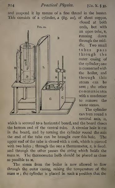
214 Practical Physics. [CH. X. 39-
and suspend it by means of a fine thread in the heater.
This consists of a cylinder, A (fig. 20), of sheet copper,
closed at both
FIG. 20. ends, but with
an open tube, B,
running down
through the mid-
dle. Two small
tubes passthrough theouter casing of
the cylinder; one
is connected with
the boiler, and
through this
steam can be
sent; the other
communicateswith a condenser
to remove the
waste steam.
The cylindercan turn round a
vertical axis, D,
which is secured to a horizontal board, and the board closes
the bottom end of the central tube. A circular hole is cut
in the board, and by turning the cylinder round the axis
the end of the tube can be brought over this hole. The
upper end of the tube is closed with a cork, which is piercedwith two holes ; through the one a thermometer, p, is fixed,
and through the other passes the string which holds the
mass M. The thermometer bulb should be placed as close
as possible to M.
The steam from the boiler is now allowed to flow
through the outer casing, raising the temperature of the
mass M; the cylinder is placed in such a position that the
CH. X. 39.] Calorimetry. 2 1 5
lower end of the tube in which M hangs is covered by the
board. The temperature in the enclosed space will rise
gradually, and it will be some time before it becomes steady,
After some considerable interval it will be found that the
thermometer reading does not alter, the mercury remaining
stationary somewhere near 100.
Note the reading ;this is the value of T in the above
equation (i).
While waiting for the body to become heated the opera-
tion of finding the water equivalent of the calorimeter maybe proceeded with.
The calorimeter consists of a copper vessel, E, which is
hung by silk threads inside a larger copper vessel, F. Theoutside of the small vessel and the inside of the large one
should be polished, to reduce the loss of heat by radiation.
This larger vessel is placed inside a wooden box, G, to
the bottom of which slides are fixed. These slides run in
grooves in the wooden baseboard of the apparatus, and the
box can be pushed easily under the board to which the
heater is attached, being just small enough to slide under it.
When the box is thus pushed into position the calorimeter
is under the hole in the board which has already been men-
tioned ;and if the cylinder be turned so that its inner tube
may come over this hole, the heated body can be dropped
directly into the calorimeter. L is a sliding screen, which
serves to protect the calorimeter from the direct radiation
of the heater, and which must be raised when it is required
to push the calorimeter under the heater.
A brass rod, H, is attached to the back of the box G, and
carries a clip in which a delicate thermometer, K, is fixed.
The thermometer bulb is in the calorimeter, a horizontal
section of which is a circle with a small square attached to
it;the thermometer is placed in the square part, and is thus
protected from injury by the mass M when it is immersed, or
by the stirrer. The stirrer is a perforated disc of copper,
with a vertical stem. A wooden cover with a slot in it,
1l6 Practical Physics. [CH. X. 39.
through which the stirrer and thermometer pass, fits over
the box o. There is a long vertical indentation in the
heater A, and the upper part of the thermometer can fit
into this when the box G is pushed into position under the
heater. Care must be taken to adjust the clip and thermo-
meter so that they will come into this indentation.
In determining the water equivalent it is important that
the experiment should be conducted under conditions as
nearly as possible the same as those which hold when the
specific heat itself is being found.
Let us suppose that it has been found, either from a
rough experiment or by calculation from an approximate
knowledge of the specific heat of the substance, that if the
calorimeter be rather more than half full of water the hot
body will raise its temperature by about 4. Then, in deter-
mining the water equivalent, we must endeavour to producea rise in temperature of about 4, starting from the same
temperature as we intend to start from in the determination
of the specific heat.
Weigh the calorimeter. Fill it rather more than half full
of water, and weigh it again. Let ;;/' be the increase in
mass observed ;this will be the mass of water in the calori-
meter;
let /' be the temperature of the water. The experi-
ment is performed by adding hot water at a-known tempera-ture to this and observing the rise in temperature. If the
hot water be poured in from a beaker or open vessel its
temperature will fall considerably before it comes in contact
with the water in the calorimeter. To avoid this there is
provided a copper vessel with an outer jacket. The inner
vessel can be filled with hot water, and the jacket prevents
it from cooling rapidly. A copper tube with a stopcock
passes out from the bottom of the vessel, and is bent ver-
tically downwards at its open end. This tube can pass
through the slot in the covering of the wooden box G close
down to the surface of the water in the calorimeter. Athermometer inserted in a cork in the top of the vessel
CH. X. 39.] Calorimetry. 217
serves to read the temperature of the hot water. For the
present purpose this may be about 30. It is not advisable
that it should be much higher.
Turn the tap of the hot-water vessel, and let some water
run into a beaker or other vessel;
this brings the tube and
tap to the same temperature as the water that will be used.
Turn the tap off, and place the calorimeter, which should be
in the wooden box, with the thermometer and stirrer in
position, underneath the tube, and then turn the tap again,
and allow the hot water to run into the calorimeter rather
slowly. The temperature of the water in the calorimeter
rises. When it has gone up about 3 stop the hot water
from flowing. Stir the water in the calorimeter well;the
temperature will continue to rise, probably about i more;note the highest point which the mercury in the thermo-
meter attains. Let the temperature be 0'. Note the tem-
perature of the hot water just before and just after it has
been allowed to flow into the calorimeter; the two will differ
very little; let the mean be T'. This may be taken as the
temperature of the hot water. Weigh the calorimeter again ;
let the increase in mass be M' grammes. This is the massof hot water which has been allowed to flow in, and which
has been cooled from T' to 0'. The heat given out is
M'(T'-0').
Tt has raised the temperature of the calorimeter, stirrer,
&c., and a mass m' of water from /' to 6'. The heat re-
quired to do this is
and this must be equal to the heat given out by the hotwater in cooling, m being, as before, the required water
equivalent.
Hence
and
218 Practical Physics. [CH. X. 39.
In doing this part of the experiment it is important that
the apparatus should be under the same conditions as when
determining the specific heat. The measurements should
be made, as we have said, with the calorimeter in the box,
and the initial and final temperatures should be as nearly as
may be the same in the two experiments. The error arising
from loss by radiation will be diminished if the experimentbe adjusted so that the final temperature is as much above
that of the room as the initial temperature was below it.
Having found the water equivalent of the calorimeter
we proceed to determine the specific heat of the substance.
The mass of the empty calorimeter is known ; fill the calori-
meter with water from one-half to two-thirds full; weigh it,
and thus determine m, the mass of the water. Replace the
calorimeter in the wooden box on the slides of the appa-
ratus, and take the temperature of the water two or three
times to see if it has become steady ;the final reading will
be the value of /. Note also the temperature of the thermd-
meter p;when it is steady raise the slide L, and push the
box G under the heater, turning the latter round the axis D
until the tube B is over the hole in the stand. Then by loosen-
ing the string which supports it drop the mass M into the
calorimeter. Draw the box back into its original position,
and note the temperature with the thermometer K, keeping
the water well stirred all the time, but being careful not to
raise the substance out of the water. When the mercurycolumn has risen to its greatest height and is just beginning
to recede read the temperature. This gives the value of 0,
the common temperature of the substance and the water.
Thus all the quantities in the equation for the specific
heat have been determined, and we have only to make the
substitution in order to find the value.
The same apparatus may be used to determine the spe-
cific heat of a liquid, either by putting the liquid into a very
thin vessel, suspending it in the heater, and proceeding in
the same way, allowing, of course, for the heat emitted by the
CH. X. 39-] Calorimetry. 219
vessel, or by using the liquid instead of water in the calori-
meter, and taking for the mass M a substance of known
specific heat. Thus c would be known, and if m be the
mass of the liquid, c its specific heat, we should have
M c (T-
6)= mc(0-t) + m l (0-t).
Hence
_ MC(T 6) _ m\
~'~m(d~t) ~m'
t, 6j and T having the same meaning as above.
Experiment. Determine by the method of mixture the spe-cific heat of the given substance, allowing for the heat absorbed
by the calorimeter &c.
Enter results thus :
Name and weight of solid. Copper 32-3 gms.
Temp, of solid in the heater . . 99-5 C.
Weight of water .... 65-4 gms.Initial temperature of water . . 12*0 C.
Common temp 157 C.
Water equivalent of calorimeter &c. 2'O
Specific Heat = '092.
Latent Heat of Water.
DEFINITION. The number of units of heat required to
convert one gramme of ice at o C. into water, without alter-
ing its temperature, is called the latent heat of water.
A weighed quantity of water at a known temperature is
contained in the calorimeter. Some pieces of ice are then
dropped in and the fall of temperature noted. When the
ice is all melted the water is weighed again, and the increase
gives the mass of ice put in. From these data, knowing the
water equivalent of the calorimeter, we can calculate the
latent heat of the water.
The ice must be in rather small pieces, so as to allow it
to melt quickly. It must also be as dry as possible. Wemay attain this by breaking the ice into fragments and
putting it piece by piece into the calorimeter, brushing off
22O Practical Physics. [CH. X. 39.
from each piece as it is put in all traces of moisture with
a brush or piece of flannel.
The ice may be lifted by means of a pair of crucible
tongs with their points wrapped in flannel. These should
have been left in the ice for some little time previously, to
acquire the temperature of o C.
Another method is to put the ice into a small basket
of fine copper gauze and leave it to drain for a few
moments, while the ice is stirred about with a glass rod,
previously cooled down to o C. by being placed in ice.
The basket is put into the calorimeter with the ice. Thewater equivalent of the basket must be allowed for, being
determined from its mass and specific heat.
Care must be taken not to put so much ice into the water
that it cannot all be melted.
The formula from which the latent heat is found is
obtained as follows : Let M be the mass of water initially,
T its temperature ; let m be the mass of ice put in, which is
given by the increase in mass of the calorimeter and con-
tents during the experiment ; let be the temperature when
all the ice is melted, m xthe water equivalent of the calori-
meter, and L the latent heat.
Then the heat given out by the water, calorimeter, etc.,
in cooling from T to is
(M + ^O (r-0).
This has melted a mass m of ice at o C., and raised the
temperature of the water formed from o to 6.
The heat required for this is
mi, + mO,
(T 0),
The temperature of the water used should be raised above
that of the room before introducing the ice, and noted just
before the ice is immersed. It is well to take a quantity
CH. X. 39.] Calorimetry. 221
of ice such that the temperature of the water at the end of
the experiment may be as much below that of the room as
it was above it initially. We may calculate this approxi-
mately, taking the latent heat of ice as 80.
Thus- suppose we have 45 grammes of water at 20, and
that the temperature of the room is ,15. Then the water
is to be cooled down to 10, or through 10.
Thus the heat absorbed from water will be 450 units.
Let us suppose we have x grammes of ice. This is
melted, and the heat absorbed thereby is 80 x x. It is also
raised in temperature from o to 10, and the heat absorbed
is x x 10.
/. 80 x+ 10 x = 450.
x =^= 5 .
90
Thus we should require about 5 grammes of ice.
(If in practice we did not know the latent heat of the
substance experimented upon at all, we should for this
purpose determine it approximately, then use our approxi-mate result to determine the right quantity of the substance
to employ in the more accurate experiment.)
Experiment. Determine the latent heat of ice.
Enter results thus :
Quantity of water . . .48 gms.Temp, water .... 20Mass of ice . . . .5 gms.Common temp . . . .10Water equivalent of calorimeter 3-5
Latent heat of water, 79.
Latent Heat of Steam.
DEFINITION. The heat required to convert a gramme of
water at 100 C. into steam without altering its temperatureis called the latent heat of steam at ioo c
C.
Steam from a boiler is passed in to a weighed quantityof water at a known temperature for a short time, and the

222 Practical Physics. [CH. X. 39.
rise of temperature noted. The contents of the calorimeter
are again weighed, and the increase in the weight of water
gives the steam which has passed in. From these data wecan calculate the latent heat of the steam by means of a
formula resembling that of the last section.
Let M be the mass of water in the calorimeter, m\ the
water equivalent, T the temperature initially, the commontemperature after a mass m of steam has been passed in, L
the latent heat of steam.
The amount of heat given out by the steam in condens-
ing to water, which is then cooled from 100 to 0, is
Lm + m (100
0).
The heat required to raise the calorimeter with the water
from T to is
and these two quantities of heat are equal.
Hence
In practice various precautions are necessary.The steam coming directly from the boiler carries with it
a large quantity ofwater, and moreover, in its passage throughthe various tubes some steam is condensed. Thus water
would enter the calorimeter with the steam, and produceconsiderable error in the result. This is avoided by sur-
rounding all the tubes with jackets and drying the steam.
To dry the steam a closed cylindrical vessel is employed,with two tubes entering it at the top and bottom, and a
hole at the top, which can be closed by a cork carrying a
thermometer. Inside this is a spiral of thin copper tubing;the spiral emerges at the top where a glass nozzle is attached
by india-rubber tubing, and terminates at the bottom in a
stop-cock.
The continuation of the stop- cock and the tube at the
top of the cylinder are attached by india-rubber tubing to the
CH. X. 39.] Calorimetry. 223
boiler;the tube at the bottom is connected with a condenser.
Thus, on putting the top of the cylinder into connection
with the boiler, a current of steam passes through the copper
cylinder, raising it and the spiral inside to the temperature
of 100.
If now we put the lower end of the spiral into communi-
cation with the boiler, the steam passes through the spiral,
emerging through the nozzle. The spiral being kept hot
at 100, the steam inside it is freed from moisture and emergesfrom the nozzle in a dry state.
The nozzle is connected with the spiral by means of a
short piece of india-rubber tubing. This should be sur-
rounded with cotton wool ; the cylindrical heater is placedinside a wooden box, and surrounded with wool, or felt, or
some other non-conducting substance.
Sometimes it is more convenient to use the boiler itself
to dry the steam ;in this case the copper spiral is placed in-
side the boiler, from which one end emerges. The other
end of the spiral inside the boiler is open above the level of
the water. The steam, before emerging from the boiler, has
to circulate through the spiral, and this dries it thoroughly.The calorimeter may conveniently take the form of a
flask, or pear-shaped vessel, of thin copper, supported by silk
threads inside another copper vessel. Its water equivalentmust be determined in the same way as has been described
in the section on specific heat (p. 216). In doing this, how-
ever, it must be remembered that the steam will probablyraise the water to a temperature considerably higher than
is the case in the determination of the specific heat of a
metal. In like manner the temperature of the fyot water
used in finding the water equivalent should be considerably
higher than that which was found most suitable in the previous
experiments ;it may with advantage be some 60 to 70.
Now water at this high temperature may cool considerablyin being poured into the calorimeter, and care must be used
to prevent loss of heat from this as far as possible.
224 Practical Physics. [CH. X. 39.
In allowing the steam to pass into the calorimeter the
following method may be adopted:See that the steam passes freely from the nozzle, and note
the temperature of the water in the calorimeter; pinch the
india-rubber tube connecting the nozzle with the calorimeter
for an instant, and immerse one end of the nozzle under the
water, then allow the steam to flow until the temperaturehas risen about 20. Raise the nozzle until its end is just
above the level of the water in the calorimeter; again pinch
the india-rubber tubing, stopping the flow of steam, and re-
move the calorimeter; note the highest point to which the
temperature rises;
this will be the value of 0, the common'
temperature.
By pinching the tube as described above, the steam is
prevented from blowing over the outer surface of the calori-
meter. If, on the other hand, the tube be pinched and the
flow stopped while the nozzle is under the water, the steam
in the nozzle at the moment will be condensed, and the at-
mospheric pressure will drive some water up into the nozzle,
and this will produce error. If the calorimeter is small there
is some danger that the steam from the nozzle may flow
directly on to the thermometer, and thus raise its tempera-ture more than that of the surrounding water. This maybe avoided by the use of a calorimeter of sufficient size.
Another method of avoiding this error, and one which will
lead to more accurate results, is the following, which has,
however, the disadvantage of requiring more elaborate
apparatus.
The calorimeter contains a spiral tube of thin copper,
ending in a closed vessel of the same material. This is
completely surrounded by water, and the dry steam is passed
through it instead of into the water. The water in the calori-
meter is kept well stirred, and the heat given out by the
steam in condensing is transmitted through the copper spiral
and vessel to the water. The rise of temperature is noted as
before, and when the temperature reaches its highest point,
CH. X. 40.] Calorimetry. 225
that is taken as the common temperature of the water, spiral,
and calorimeter. The heat absorbed by the spiral and
vessel is determined with the water equivalent ; the quantity
of water in the spiral at the end gives the mass of steam con-
densed. (See Regnault's paper on the 'Latent Heat of
Steam.' Memoires de VAcademie, T. XXL)The calculation is proceeded with in the usual way.
Experiment. Determine the latent heat of steam.
Enter the results as below :
Weight of water in calorimeter . . . . 22i'3gms.
Temp I4'5 C.
Weight of steam let in . . , . . 10*4 gms.
Temp, of steam given by thermometer in heater 100
Common temp, of mixture . , . . . 41 C.
Water equivalent of cal 10-9
Latent heat of steam . . . , .5327
40. The Method of Cooling. To determine the Specific
Heat of a Liquid.
A known weight of the liquid is put into a copper vessel
with a thermometer. This is hung by means of silk threads,
like the calorimeter, inside another copper vessel which is
closed by a lid with a cork in it supporting the thermometer.
The exterior vessel is kept in a large bath of water at a
known temperature, the bath being kept well stirred. It is
intended to be maintained at the temperature of the room
throughout the experiment ; the bath is simply to ensure
this. A small stirrer should pass through the cork which
holds the thermometer, to keep the liquid well stirred. Theouter surface of the inner vessel and the inner surface of
the outer should be coated with lampblack.The liquid is heated up to, say, 70 or 80, and then put
into the calorimeter.
Allow the liquid to cool, and note the intervals taken
by it to cool, through; say, each successive degree. If the
Q
226 Practical Physics. [CH. X. 40.
rate of cooling is too rapid to allow this to be done, note
the intervals for each 5 or 10, and calculate from these
observations the mean rate of cooling for the range ex-
perimented on, say from 70 to 30.
Suppose we find that, on the average, it cools 3 in a
minute. Then, if the liquid weigh 25 grammes and its
specific heat be<r,the quantity of heat which leaves it in one
minute is 25 X3 x<r.
Now empty the liquid out from the calorimeter and per-
form a similar experiment with water instead. The water
should fill the calorimeter to the same level, and be raised
to the same temperature as the liquid previously used.
Let us now suppose that there are 32 grammes of water,
and that the temperature of the wate. falls through "9 of a
degree in one minute;
thus the quantity of heat which
escapes from the water per minute is 32 x "9 units.
The quantity of heat radiated from one surface at a given
temperature to another at a constant lower temperature de-
pends solely on the nature and material of the surfaces and
the temperature of the warmer. *
In the two experiments described above, the surfaces
are of the same nature;thus the rate at which heat escapes
must be the same for the two experiments at the same tem-
peratures,
.*. 25 x 3 x<r=32 x'9,
^=384.We can get the result required from the observations
more quickly thus :- --
Observe the time it takes the temperature to fall, say,
from 60 to 55 in the two cases; let it be t^ minutes and
t2 minutes respectively.
Then the fall of temperature per minute in the two cases
respectively is 5//Aand 5//2 .
The amount of heat which is transferred in the first case
1 See Garnett, Heat, ch. ix. Deschanel, Natural Philosophy,
p. 399, &c.
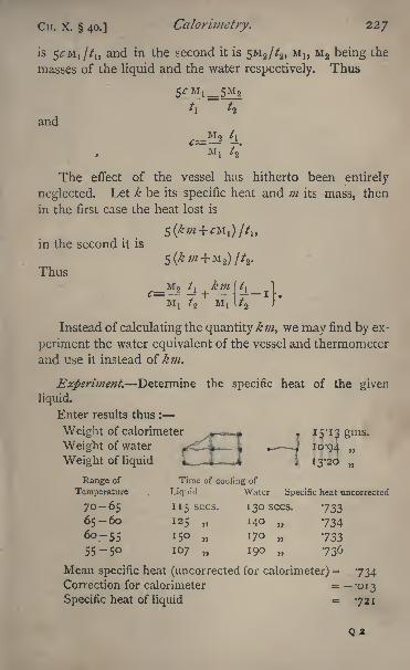
Cn. X. 40.] Calorimetry. 227
is 5<:M 1 //1) and in the second it is 5M 2 //2 ,M I} M 2 being the
masses of the liquid and the water respectively. Thus
and
The effect of the vessel has hitherto been entirely
neglected. Let k be its specific heat and m its mass, then
in the first case the heat lost is
in the second it is
Thus
M
Instead of calculating the quantity km^ we may find by ex-
periment the water equivalent of the vessel and thermometer
and use it instead of km.
Experiment. Determine the specific heat of the given
liquid.
Enter results thus :
Weight of calorimeter , . 15-13 gms.
Weight of water f _-4-^i . J 10-94
Weight of liquid \ _ $ - > 1 13-20
Range of Time of cooling of
Temperature . Liquid Water Specific heat uncorrected
70-65 115 sees. 1 30 sees. -733
65-60 125 140 7346o-55 150 170 73355-50 107 190 736
Mean specific heat (uncorrected for calorimeter) = 734Correction for calorimeter = -013
Specific heat of liquid = 721
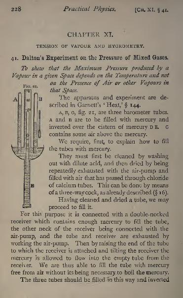
228 Practical Physics. [Cn. XI. 41.
FIG. 21.
CHAPTER XL
TENSION OF VAPOUR AND HYGROMETRY.
41. Dalton's Experiment on the Pressure of Mixed Gases.
To shew that the Maximum Pressure produced by a
Vapour in a given Space depends on the Temperature and not
on the Presence of Air or other Vapours in
that Space,
The apparatus and experiment are de-
scribed in Garnett's '
Heat,' 144.
A, B, G3 fig. 21, are three barometer tubes.
A and B are to be filled with mercury and
inverted over the cistern of mercury D E. G
contains some air above the mercury.We require, first^ to explain how to fill
the tubes with mercury.
They must first be cleaned by washingout with dilute acid, and then dried by being
repeatedly exhausted with the air-pump and
filled with air that has passed through chloride
of calcium tubes. This can be done by means
ofa three-way cock, as already described ( 16).
Having cleaned and dried a tube, we mayproceed to fill it.
For this purpose it is connected with a double-necked
receiver which contains enough mercury to fill the tube,
the other neck of the receiver being connected with the
air-pump, and the tube and receiver are exhausted by
working the air-pump. Then by raising the end of the tube
to which the receiver is attached and tilting the receiver the
mercury is allowed to flow into the empty tube from the
receiver. We are thus able to fill the tube with mercuryfree from air without its being necessary to boil the mercury.
The three tubes should be filled in this way and inverted
CH. XI. 41.] Tension of Vapour and Hygrometry. 229
over the mercury cistern. A convenient arrangement for
the latter is a hemispherical iron basin screwed on -to the
end of a piece of iron tubing, the lower end of the tubing
being closed.
Connect the open end of G by means of a bent piece of
small-sized glass tubing with the drying tubes, and allow a
small quantity of dry air to flow in. The amount of air
introduced should be such as to cause the mercury in G to
rise to about half the height that it reaches in A and B.
The quantity can be regulated by pinching the india-rubber
tube which connects G with the drying tubes.
Adjust in a vertical position behind the three tubes a
scale of millimetres, and hang up close to them a thermo-
meter. Place a telescope at some distance off, so as to read
on the millimetre scale the height at which the mercurycolumns stand and also the thermometer. The tube G
should be so placed that it can be depressed into the
iron tubing below the cistern.
Mark the height at which the mercury stands in G by means
of a piece of gummed paper fastened on round the tube.
Read on the millimetre scale the heights of A, B, and G,
above the level of the mercury in the cistern.
Suppose the readings are
A B G
765 765 524
Introduce, by the aid of a pipette with a bent nozzle, a
little ether into B and G, putting into each tube just so muchthat a small quantity of the liquid rests above the mercury.
The mercury in B will fall. The amount of fall will
depend on the temperature. Let us suppose that the new
reading in B is 354 mm., then the mercury has fallen through
765 354 mm.;thus the ether exerts a pressure equivalent
to that of 411 mm. of mercury.The mercury in G will fall also, but not by so much as
that in B, for the pressure in G is the pressure of the ether
230 Practical Physics. [CH. XI. 41.
vapour together with that of the contained air ; and as the
mercury falls, the volume of the contained air increases and
its pressure consequently decreases. 1
Now lower the tube G in the cistern until the level of
the mercury in G just comes back again to the paper mark.
The volume of the contained air is now the same as before,
therefore so also is its pressure. The depression of the
mercury column in G below its original height is due there-
fore to the pressure of the ether vapour. Now read the
height of G on the scale;
it will be found to be about
113 mm. The column in G, therefore, has been depressed
through 524113 mm., or 411 mm. Thus B and G are
depressed through equal amounts provided that the volume
of air in G is allowed to remain the same.
The assumption has been made that the temperature
remains constant during the experiment. This will not be
far from the truth in the laboratory, provided that the read-
ings are taken from a distance so as to avoid the heating
effects of the body ;if necessary, a correction must be applied
for a change in temperature.
Having made these measurements, depress B into the
iron tube;
it will be found that the consequence is simply
to increase the amount of condensed liquid above the sur-
face of B without altering the height of that surface.
The difference between the heights of the columns in A
and B gives in millimetres of mercury the maximum pressure
which can be exerted by ether vapour at the temperature of
the laboratory.
Experiment. Determine the maximum pressure exerted bythe vapour of ether at the temperature of the laboratory, and
shew that it is independent of the presence of air.
Enter results thus :
Height of mercury in A = 765 mm.
1 The presence of the air in G retards the evaporation of the ether ;
considerable time must therefore be allowed for the mercury to arrive
at its final level.
CH. XT. 41.] Tension of Vapour and Hygrometry. 231
Height of mercury in B
initially . , . , . . 765 mm.after introduction of ether . . 354
Pressure of ether vapour . . . . 411
Height of mercury in Ginitially 524after introduction of ether . , 113
Pressure of ether vapour . . . 411
Temperature I5*5 throughout.
HYGROMETRY.
Tension ofAqueous Vapour.^^z determination of the
amount of water contained in the atmosphere as vapour is
a problem of great importance, especially to meteorology.There are several ways in which we may attempt to makethe determination, and the result of the experiment mayalso be variously expressed. The quantity of water which
can be contained in air at a given temperature is limited bythe condition that the pressure
l of the vapour (considered
independently of the pressure of the atmosphere containing
it) cannot exceed a certain amount, which is definite for a
definite temperature, and which for temperatures usually
occurring, viz. between - 10 C. and -^30 C., lies between
2 mm. of mercury and 31*5 mm. Dalton concluded, from
experiments of his own, that this maximum pressure, which
water vapour could exert when in the atmosphere, was the
same as that which the vapour could exert if the air were
removed, and indeed that the dry air and the vapour pressedthe sides of the vessel containing them with a pressure
entirely independent one of the other, the sum of the two
being the resultant pressure of the damp air (see the previous experiment, 41). This law of Dalton's has been
shewn by Regnault to be true, within small limits of error,
at different temperatures for saturated air, that is, for air
which contains as much vapour as possible ;and it is now
1 The words ' tension' and *
pressure'are here used, in accordance
with custom, as synonymous.
232 Practical Physics. [CH. XI. 41.
a generally accepted principle, not only for the vapour of
water and air, but for all gases and vapours which do not
act chemically upon one another, and accordingly one of
the most usual methods of expressing the state of the air
with respect to the moisture it contains is to quote the
pressure exerted by the moisture at the time of the ob-
servation. Let this be denoted by e then by saying that
the pressure of aqueous vapour in the atmosphere is e,
we mean that if we enclose a quantity of the air without
altering its pressure, we shall reduce its pressure by e, if we
remove from it, by any means, the whole of its water with-
out altering its volume. The quantity we have denoted
by e is often called the tension of aqueous vapour in the air.
Relative Humidity. From what has gone before, it will
be understood that when the temperature of the air is
known we can find by means of a table of pressures of
water vapour in vacuo the maximum pressure which water
vapour can exert in the atmosphere. This may be called
the saturation tension for that temperature. Let the tem-
perature be / and the saturation tension en then if the actual
tension at the time be *, the so-called fraction of saturation
will be- and the percentage of saturation will be*t e
t
This is known as the relative humidity.
Dew Point. If we suppose a mass of moist air to be
enclosed in a perfectly flexible envelope, which prevents its
mixing with the surrounding air but exerts no additional pres-
sure upon it, and suppose this enclosed air to be gradually di-
minished in temperature, a little consideration will shew that
if both the dry air and vapour are subject to the same laws
of contraction from diminution of temperature under con-
stant pressure,1 the dry air and vapour will contract the same
fraction of their volume, but the pressure of each will be
1 The condition here stated has been proved by the experiments of
Regnault, Herwig, and others, to be very nearijr fulfilled in the case of waterra pour.
CH. XT. 41.] Tension of Vapour and Hygtometry. 233
always the same as it was originally, the sum of the two
being always equal to the atmospheric pressure on the
outside of the envelope.
If, then, the tension of aqueous vapour in the original
air was e, we shall by continual cooling arrive at a tempe-
rature let us call it T at which e is the saturation tension ;
and if we cool the air below that we must get some of the
moisture deposited as a cloud or as dew. This temperature
is therefore known as the dew point.
If we then determine the dew point to be T, we can
find <?,the tension of aqueous vapour in the air at the time,
by looking out in the table of tensions ev the saturation
tension at T, and we have by the foregoing reasoning
42. The Chemical Method of Determining the Densityof Aqueous Vapour in the Air,
It is not easy to arrange experiments to determine
directly, with sufficient accuracy, the diminution in pressure
of a mass of air when all moisture shall have been ab-
stracted without alteration of volume, but we may attack
the problem indirectly. Let us suppose that we determine
the weightJn grammes of the moisture which is contained in
a cubic metre of the air as we find it at the temperature t
and with a barometric pressure H.
Then this weight is properly called the actual density of
the aqueous vapour in the air at the time, in grammes percubic metre. Let this be denoted by d, and let us denote
by 8 the specific gravity of the aqueous vapour referred to
air at the same pressure e and the same temperature /, and
moreover let w be the density of air at o C. and 760 mm.
pressure expressed in grammes per cubic metre. Then the
density of air at the pressure e and temperature /, also ex-
pressed in grammes per cubic metre, is equal to-~
234 Practical Physics. [CH. XI. 42.
where a = coefficient of expansion of gases per degree
centigrade, and therefore
760(1 + 00'
or e= 76 (l
b IV
Now w is known to be 1293 and a = '00366 ;
-e = d ,,
12938
If, therefore, we know the value of 8 for the conditions
of the air under experiment, we can calculate the tension of
the vapour when we know its actual density. Now, for
water vapour which is not near its point of saturation 8
is equal to '622 for all temperatures and pressures. It
would be always constant and equal to "622 if the vapourfollowed the gaseous laws up to saturation pressure. That is
however, not strictly the case, and yet Regnault has shewn
by a series of experiments on saturated air that the for-
mula e = 7_6o(i_+joo366_/)^ guffices tQ iye accuratel the1293 X '022
tension when d is known, even for air which is saturated,
or nearly so, with vapour.
We have still to shew how to determine d. This can
be done if we cause, by means of an aspirator, a knownvolume of air to pass over some substance which will entirely
absorb from the air the moisture and nothing else, and
determine the increase of weight thus produced. Such a
substance is sulphuric acid with a specific gravity of i '84.
To facilitate the absorption, the sulphuric acid is allowed to
soak into small fragments of pumice contained in a U-tube.
The pumice should be first broken into fragments about the
size of a pea, then treated with sulphuric acid and heated
to redness, to decompose any chlorides, &c., which may be
contained in it. The U-tubes may then be filled with the
fragments, and the strong sulphuric acid poured on till the
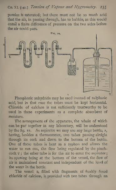
CH. XI. 42.] Tension of Vapour and Hygrometry. 235
pumice is saturated; but there must not be so much acid
that the air, in passing through, has to bubble, as this would
entail a finite difference of pressure on the two sides before
the air could pass.
FIG. a.
i
Phosphoric anhydride may be used instead of sulphuric
acid, but in that case the tubes must be kept horizontal.
Chloride of calcium is not sufficiently trustworthy to be
used in these experiments as a complete absorbent of
moisture.
The arrangement of the apparatus, the whole of which
can be pur together in any laboratory, will be understood
by the fig. 22. As aspirator we may use any large bottle, A,
having, besides a thermometer, two tubes passing airtight
through its cork and down to the bottom of the bottle.
One of these tubes is bent as a syphon and allows the
water to run out, the flow being regulated by the pinch-
cock T;the other tube is for the air to enter the aspirator ;
its opening being at the bottom of the vessel, the flow of
air is maintained constant and independent of the level of
the water in the bottle.
The vessel B, filled with fragments of freshly fused
chloride of calcium, is provided with two tubes through an
236 Practical Physics. [Cn. XL 42.
airtight cork, one, connected with the aspirator, passing just
through, and the other, connected with the drying tube D,
to the bottom of the vessel. This serves as a valve to
prevent any moisture reaching the tubes from the aspira-
tor. The most convenient way of connecting up dryingtubes is by means of mercury cups, consisting of short
glass tubes with a cork bottom perforated for a narrow tube;
over this passes one limb of an inverted U-tube, the other
limb of which is secured to one limb of the drying tube
either by an india-rubber washer with paraffin or, still better,
by being thickened and ground as a stopper. A glance at
the figure will shew the arrangement. The drying tubes can
then be removed and replaced with facility, and a perfectly
airtight connection is ensured. The space in the little
cups, M, M, M, M, between the narrow tubes and the limbs
of the inverted U's is closed by mercury. Care must be
taken to close the ends of the inverted U's with small
bungs during weighing, and to see that no globules of mer-
cury are adhering to the glass. The connecting tubes c
between the drying tubes should be of glass and as short as
possible.
Two drying tubes must be used, and weighed separately
before and after the experiment ;the first will, when in
good order, entirely absorb the moisture, but if the air is
passed with too great rapidity, or if the acid has become
too dilute by continued use, the second tube will make the
fact apparent. A thermometer, x, to determine the tem-
perature of the air passing into the tubes is also necessary.
To take an observation, the tubes are weighed and
placed in position, the vessel A filled with water, the
syphon tube filled, and the tube at the end of the drying
tubes closed by means of a pinch-tap. Then, on openingthe tap at T, no water should flow out
;if any does there
is some leak in the apparatus which must be made tight
before proceeding further. When assured that any air
supplied to the aspirator will pass through the drying tubes,
the observation may be begun. The water is run out slowly
CH. XI. 42.] Tension of Vapour and Hygrometry. 237
^at about the rate of i litre in ten minutes) into a litre flask,
and when the latter is filled up to the scratch on the neck
it is removed and weighed, its place being taken by another
flask, which can go on filling during the weighing of the
first. This is repeated until the aspirator is empty, when,
the weight of the empty flasks being ascertained, the
total weight of water thus replaced by air can be found.
The height H of the barometer must be determined at the
beginning and end of the experiment. During the observa-
tion the thermometer x must be read every ten minutes,
and the mean of the readings taken as the temperature / of
the entering air;the thermometer in the aspirator must be
read at the end of the experiment ;let the reading be t'. If
the aspirator A is but small, it can be refilled and the ex-
periment repeated, and we may of course determine, once
for all, the volume of water which can be run out of the
aspirator when filled up to a certain mark in the manner thus
described ;but as an exercise it is better to re-determine it
for each experiment.From the weight of water run out, with the assistance of
Table 32 (Lupton, p. 28) we can determine the volume v of
air taking the, place of the water in the aspirator, v beingmeasured in cubic metres. This air is evidently saturated
with water at the temperature f-, its pressure is the baro-
metric pressure, and therefore the pressure of the dry air in
it is H en et, being the saturation tension at ?. When it
entered the drying tubes this air had a pressure H<?,
and
its temperature was /, e being the tension whose value weare seeking. The volume of the air was, therefore, then
/2 \
Hence, if w be the increase of weight of the drying tubes
in grammes, we shall have for d the actual density of the
moisture in the air;
H e
238 Practical Physics. [CH. XI. 42.
We thus obtain the quantity d ; substituting its value from
equation (i) above, we get
1293 x -622 _(H. e)(i+a?)w760(1 + at)
~(H ^,)(i + a/)v'
or
e _ 760 i+af w /
^
H e 1293 x "622'
H et
*
v
Experiment. Determine the density of the aqueous vapourin the air, and also its tension.
Enter results thus :
Temperature of air ..... 2i7Temperature of aspirator . . . . . 2i'5Volume of aspirator 36061 cc.
Gain of weight of tube (i) . . . . "5655 gm.
(2) .... -ooi i gm.
Total ...... '5666 gm.* =16-08.
43. Dines's Hygrometer. Wet and Dry Bulb
Thermometers.
Dines's Hygrometer is an instrument for directly deter-
mining the dew-point, i.e. the temperature at which the air
in the neighbourhood of the instrument is completely satu-
rated with aqueous vapour. It consists of a thermometer
placed horizontally, so that its stem is visible while its bulb
is enclosed in a box of thin copper through which cold water
can be passed from a reservoir attached to the instrument by
turning the tap at the back. The tap is full on when the
side marked o is upward, and shut off when that marked s
is upward. The bulb of the thermometer is placed close to
the top of the box which encloses it, and the top of the
box is formed of a plate of blackened glass, ground very
thin indeed, in order, as far as possible, to avoid anydifference of temperature between the upper and under
CH. XI. 43.] Tension of Vapour. and Hygrometry. 239
surfaces, and so to ensure that the temperature of the
thermometer shall be the same as that of the upper surface
of the glass.
The temperature of the box is cooled very gradually by
allowing water, previously cooled by adding ice, to pass
very slowly from the reservoir along the tube. As soon as
the surface of the glass is at a temperature below that of
the dew point, a deposit of dew can be observed on it.
This can be easily noticed by placing the instrument so
that the glass surface reflects the light of the sky, and
accordingly presents a uniform appearance which is at once
disturbed by a deposit of dew. The temperature /, say,
at which this occurs is of course below the dew-point. Thefilm of moisture is then allowed to evaporate, and when all
has disappeared the temperature is again read let it be f.
This must be accordingly above the dew-point. Now allow
the water to flow only drop by drop, cooling the surface
very slowly indeed, and observe the same phenomena again,
until t and f are not more than one or two tenths of a
degree apart. Then we know that the dew-point lies between
them, and by taking the mean of the two obtain an accuracysufficient for practical purposes. The fall of temperaturecan in some cases be made so slow that a fugitive depositforms and disappears at the same temperature, in which
case the temperature of the dew-point is indicated by the
thermometer as accurately as the variation of the quantity to
be observed permits.
It is important that the observer should be as far as
possible from the glass surface during the observation, in
order to avoid a premature deposit of moisture. To this
end a telescope must be mounted so as to read the thermo-
meter at a distance, placing a mirror to reflect the scale of
the thermometer to the telescope.
We may thus determine the dew-point, but the usual
object of a hygrometric observation is to determine the ten-
sion of aquecus vapour in the air at the time of observing.
240 Practical Physics. [CH. XI. 43.
We may suppose the air in the neighbourhood of the de-
positing surface to be reduced to such a state that it will
deposit moisture, by altering its temperature merely, without
altering its pressure, and accordingly without altering the
tension of aqueous vapour contained in it. We have
therefore, only to look out in a table the saturation tension
of aqueous vapour at the temperature of the dew-point and
we obtain at once the quantity desired, viz. the tension of
vapour in the air before it was cooled.
We may compare the result thus obtained with that
given by the wet and dry bulb thermometers. In this case
the observation consists simply in reading the temperatureof the air /, and the temperature f of a thermometer whose
bulb is covered with muslin, which is kept constantly moist
by means of a wick leading from a supply of water. Thewick and muslin must have been previously boiled in a
dilute solution of an alkali and well washed before being
mounted, as otherwise they rapidly lose the power of keep-
ing up a supply of moisture from the vessel.
The tension e" of aqueous vapour can be deduced from
the observations of / and f by Regnault's formula 1
(available
when f is higher than the freezing point)
e" = e'- -0009739 f(t-f)- -5941(^-0-ooo8(;- /')(- 755)
where e? is the saturation tension of aqueous vapour at the
temperature /', and b is the barometric height in millimetres.
Experiments. Determine the dew-point and the tension of
aqueous vapour by Dines's Hygrometer, and also by the wet and
dry bulb thermometer.
1 The reduction of observations with the wet and dry bnlb ther-
mometers is generally effected by means of tables, a set of which is
issued by the Meteorological Office. The formula here quoted is Reg-nault's formula (Ann. de Chimie, 1845) as modified by Jelinck. See
Lupton, table 35.
Cn. XI. 43.] Tension of Vapour and Hygromctty. 241
Enter the results thus :
Appearance of dew . . . 47-! F.
Disappearance of dew . . . . 4775Dew-point 47'42Tension of aqueous vapour deduced . 8*28 mm.Tension of aqueous vapour from wet
and dry bulb . . . . .8-9 mm.
44. Regnault's Hygrometer.
Regnault's hygrometer consists of a brightly polished
thimble of very thin silver, forming the continuation of a
short glass tube to which the silver thimble is attached by
plaster of paris or some other cement not acted upon byether. Through a cork fitting tightly into the top of the
glass tube pass two narrow tubes of glass, one (A) going to
the bottom of the thimble, the other (B) opening at the top
of the vessel just below the cork; also a sensitive thermo-
meter so placed that when the cork is in position, the bulb
(which should be a small one) is close to the bottom of the
thimble.
If, then, ether be poured into the thimble until it more
than covers the thermometer bulb, air can be made to
bubble through the liquid either by blowing into the tube (A)
or sucking air through (B) by means of an aspirating pumpof any sort. The passage of the air through the ether
causes it to evaporate and the temperature of the liquid to
fall in consequence, while the bubbling ensures the mixingof the different layers of liquid, and therefore very approxi-
mately, at any rate, a uniform temperature of silver, ether,
and thermometer. The passage of air is continued until a
deposit of dew is seen on the silver, which shews that the tem-
perature of the silver is below the dew-point. The thermo-
meter is then read, and the temperature of the apparatusallowed to rise until the deposit of moisture has completely
disappeared, when the thermometer is again read. The
temperature is now above that of the dew-point, and the
R
242 Practical Physics. [CH. XI. 44.
mean of the two readings so obtained may be taken as the
temperature of the dew-point, provided that there is no
more difference than two or three tenths of a degree centi-
grade between them.
In case the difference between the temperatures of ap-
pearance and disappearance is a large one, the method of
proceeding suggested by Regnault should be adopted. Thefirst observation will probably have given the temperatureof dew appearance within a degree; say the observation was
5; pass air again through the ether and watch the ther-
mometer, and stop when a temperature of 6 is shewn.
Then aspirate slowly, watching the thermometer all the
time. Stop as each fifth of a degree is passed to ascertain
if there be a deposit of dew. As soon as such a deposit is
formed, stop aspirating, and the deposit will probably dis-
appear before the temperature has risen o'2, and we thus
obtain the dew-point correct to o'i.
The thermometer should be read by means of a tele-
scope some 6 feet away from the instrument, and every care
should be taken to prevent the presence of the observer
producing a direct effect upon the apparatus.
It is sometimes very difficult, and never very easy, to be
certain whether or not there is a deposit of dew on the
silver, the difficulty varying with different states of the light.
It is generally best to have a uniform light-grey backgroundof paper or cloth, but no very definite rule can be given,
practice being the only satisfactory guide in the matter.
A modification of Regnault's apparatus by M. Alluard,
in which the silver thimble is replaced by a rectangular brass
box, one face of which is surrounded by a brass plate, is
a more convenient instrument;the contrast between the
two polished surfaces, one of which may be covered with
the dew while the other does not vary, enables the appear-ance of the deposit to be judged with greater facility. Themethod of using the instrument is the same ar, for Regnault's.
The dew-point being ascertainecl-as described, the ten-
CH. XI. 44.] Tension of Vapour and Hygrometry. 243
sion of aqueous vapour corresponding to the temperatureof the dew-point is given in the table of tensions based on
Regnault's experiments,1 since at the dew-point the air is
saturated with vapour. We have already seen (p. 233) that
we may take the saturation tension of vapour at the dew-
point as representing the actual tension of aqueous vapourat the time of the experiment.
Experiment. Determine the dew-point by Regnault's Hy-grometer, and deduce the tension of aqueous vapour.
Enter results thus :
Appearance of dew .... 47'! F.
Disappearance . . . . 47 '75
Dew-point . . -. . . .47-42Tension of aqueous vapour. . . B '28 mm.
CHAPTER XII.
PHOTOMETRY.
THE first experiments to be performed in optics will be
on the comparison of the intensities of two sources of light.
We shall describe two simple methods for this, Bunsen's and
Rumford's, both founded on the law that the intensity ot
the illumination from a given point varies directly as the
cosine of the angle of incidence upon the illuminated surface
and inversely as the square of the distance of the surface
from the luminous point. So that if I, I' be the illuminat-
ing powers of two sources distant r, r1
respectively from a
given surface, on which the light from each falls at the same
angle, the illumination from the two will be respectively
l/r2 and I'jr'
2,and if these are equal we have
so that by measuring the distances r and r1 we can find the
ratio of I to I7.
1Lupton's Tables, No. 34.
14
244 Practical Physics. [CH. XII. 44 .
Now this supposes that it is possible to make the illumi-
nation from each source of light the same by varying the
distances of the two sources from the screen. As a matter
of fact, this is not necessarily the case;
in performing the
experiment we compare the two illuminations by the effect
produced on the eye, and that effect depends partly on the
quantity of energy in the beam of light reaching the eye,
partly on the nature of the rays of which that beam is
composed. To define the intensity of a beam, we require
to know, not merely the quantity of light in it, but also howthat light is distributed among the differently coloured rays
of which the beam is composed. Any given source emits
rays, probably of an infinite number of different colours.
The effect produced on the eye depends on the proportionin which these different colours are mixed. If they are
mixed in different proportions in the two beams we are
considering, it will be impossible for the effect of each of
the two, in illuminating a given surface, ever to appear the
same to the eye.
This constitutes the great difficulty of all simple photo-metric measurements. Two different sources of light, a gas
flame and a candle for example, emit differently coloured
rays in different proportions ;the gas light contains more
blue than the candle for the same total quantity of light,
and so of the two spaces on which the illumination is to be
the same, the one will appear bluish, the other reddish.
Strictly, then, two different sources of light can only be
compared by the use of a spectro-photometer, an instrument
which forms the light from each source into a spectrum and
then enables the observer to compare the intensity of the
two for the different parts of the spectrum. One such in-
strument will be described in a subsequent section( 67).
45. Bunsen's Photometer.
Two standard sperm candles (see p. 23) are used as the
standard of comparison. These are suspended from the arm
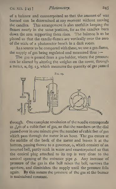
Cir. XII. 45] Photometry. 245
of a balance and counterpoised so that the amount of wax
burned can be determined at any moment without movingthe candles. This arrangement is also useful in keeping the
flames nearly in the same position, for as the candles burn
down the arm supporting them rises. The balance is to be
placed so that the candle-flames are vertically over the zero
of the scale of a photometer bench in a dark room.
As a source to be compared with these, we use a gas-flame,
the supply of gas being regulated and measured thus :
The gas is passed from a gas-holder, where the pressure
can be altered by altering the weights on the cover, through
a meter, M, fig. 23, which measures the quantity of gas passed
FIG. 23.
through. One complete revolution of the needle correspondsto 6%th of a cubic foot of gas, so that the numbers on the dial
passed over in one minute give the number ofcubic feet of gaswhich pass through the meter in an hour. The gas enters at
the middle of the back of the meter and leaves it at the
bottom, passing thence to a governor, G, which consists of an
inverted bell, partly sunk in water and counterpoised so that
the conical plug attached to its top is very close to the
conical opening of the entrance pipe q. Any increase of
pressure of the gas in the bell raises the bell, narrows the
aperture, and diminishes the supply until the pressure falls
again. By this means the pressure of the gas at the burner
is maintained constant.
246 Practical Physics. CH. XII. 45,
The exit pipe from the bell passes to a tube with two
stopcocks s, s'. The stopcock s' is provided with a screw
adjustment for regulating the supply of gas with extreme
nicety; the stopcock s can then be used, being alwayseither turned on full or quite shut, so as to always reproducethe same flame without the trouble of finely adjusting every
time. Between these two stopcocks is a manometer M for
measuring the pressure of the gas as it burns.
In stating, therefore, the gas-flame employed, we have
to put down (i) the burner employed ; (2) the pressure of
the gas ; (3) the amount of gas passing through the meter
per hour. 1
The gas passes from the stopcocks to the burner, which
is fixed on one of the sliding stands of the photometer bar,
so that the plane of the flame corresponds to the fiducial
mark on the stand. On another sliding stand between the
burner and the candles is placed the photometer disc, which
consists of a grease spot upon white paper.
The method consists in sliding the photometer disc
along the scale until the spot appears of the same brightness
as the rest of the paper ;the intensities of the lights are then
proportional to the squares of their distances from the disc.
The observations should be made by viewing the disc
from either side, as it will often be found that when the
spot and the rest of the disc appear to be of the same
brightness when viewed from one side, they will differ con-
siderably when viewed from the other. This is due, in
part, at any rate, to want of uniformity in the two surfaces
of the paper of which the disc is made;
if the difference be
very marked, that disc must be rejected and another used.
In all cases, however, observations should be made from
each side and the mean taken.
The sources of light should be screened by blackened
1 In order to test the '
lighting power of gas'
with a standard
argand burner, the flow through the meter must be adjusted to 5 cubic
feet per hour by means of the micrometer tap.
CH. XII. 45.] Photometry. 247
screens, and the position of the disc determined by several
independent observations, and the mean taken.
The lights must be very nearly of the same colour,
otherwise it will be impossible to obtain the appearance of
equality of illumination over the whole disc. (This may be
tried by interposing a coloured glass between one of the
lights and the disc.) Instead of trying to find a position
in which the disc presents a uniform appearance on one
side, the position in which it appears the same as viewed
from two corresponding points, one on each side, may be
sought for. For additional details see the 'Gas Analysts'
Manual,' p. 40, 61, 84.
Experiment. Compare the illuminating power of the gas-
flame with that of the standard candle.
Additional experiments. (a) Compare the intensities of the
candles and standard argand burner
(1) Directly.
(2) With a thin plate of glass interposed between one source
and the disc. This will give the amount of light lost by reflection
and by the absorption of the glass. By rotating the glass plate
the variations in the loss at different angles may be tested.
(3) With a thin plite of glass between one source and the
disc, and a thick plate on the other side. This will enable youto determine the amount of light lost by the absorption of a
thickness of glass equal to the difference of the thicknesses of
the two plates.
(b) Obtain two burners and arrange them in connection with
a three-way tube. Cover one up by a screen, and measure the
intensity of the other. Then interchange them, and so obtain
the intensity of each separately. Then place them togetherso that the two flames unite, and measure the intensity of the
combined flame and its relation to the sum of the intensities of
each.
(c] Test the intensity of the light from the same amcuat of
gas used in different burners.
Enter results thus :
Gas burning at the rate of 5 cubic feet per hour.
Candles 16-2 gins. ,.
248 Practical Physics. [CH. XII. 45.
Mean distance of Mean distance of Ratio of illuminatinggas candles powers
75 3i 5-85
68 29 5-49
60 25 576'
52 22 5-59
46 19 5-86
Mean ratio of illuminating powers 571.
46. Rumford's Photometer.
The apparatus for making the comparison consists
simply of a bar, at the end of which a ground glass
or paper screen is fixed, and on which a support is made to
slide, carrying the gas jet or other source of light.
On the bar, and in front of the screen, is placed a
w.ooden rod, about 3 inches from the screen. The two lights
to be compared are placed one on the sliding support and
the other on the table at a fixed distance (taking care that
both are the same height), the positions being so adjustedthat the two shadows of the rod thrown on the screen are
just in contact with each other without overlapping. Thescreen must be turned so that it makes equal angles with
the direction of the light from each source. The distance
of the sliding light has to be adjusted so that the two
shadows are of the same depth.
Consider a unit of area, e.g. a square centimetre, of each
shadow A and B;
let the distance of the unit of area of A
from the two sources of light be x, x, and let the distance of
the unit of area of the shadow B from the same sources be
>', Y respectively. Then the unit of area of A is illuminated
only by the one source of light, distant x from it, and
therefore its illumination is I/x2,where I is the illumination
per unit area at unit distance from the source. The unit
of area of B is illuminated only by the source of light at dis-
tance y, and the illumination therefore is F/jy2,when V is the
illumination per unit area at unit distance from the second
source.
CH. XII. 46.] Photometry. 249
Hence, since the illuminations of the shadowed portions
\of the screen are equal,
I= F *=**x2 /
"T y*
If the two unit areas considered be immediately ad-
jacent to the line of junction of the shadows, then we maymeasure x and y from the same point. Hence the ratio
of the intensities of the two sources is the square of the
ratio of the distances of the two sources from the line of
contact of the shadows. The method has the advantage that
the observations do not need a dark room.
The shadows may be so arranged that the line of contact
is on the middle line of the bar on which the one source slides,
and accordingly the distance may be measured along the
bar. The other distance may be measured by a tape.
The arrangements necessary for determining the rate at
which the gas is being burnt or the quantity of wax con-
sumed are described in section 45.
Experiment. Compare the illuminating power of the gas-flame and standard candle.
Enter results thus :
Candle burns at the rate of 8'i gins, per hour.
Gas 5 cubic feet per hour.
Distance of gas Distance of candle Ratio of illuminatingpowers
I28-5 39'5 I0'5
98 30-5 10-4
Mean ratio of illuminating powers 10-45
2SO Practical Physics. [CH. XIII. 47.
CHAPTER XIII.
MIRRORS AND LENSES.
NEARLY all the methods used in optical measurements are
indirect. The quantity required is deduced by calculation
from the quantities actually measured, or the law to be
demonstrated is inferred from the observations made bya process of reasoning. This is illustrated by the following
experiment on the law of reflexion and by the experiments on
focal lengths. The law of refraction may also be verified
by the measurements of the refractive index of a transparent
medium.
47. Verification of the Law of Reflexion of Light.
In order to prove the law, that the angle which a reflected
ray makes with the normal to a plane surface is equal to
the angle made by the incident ray with the normal, and
that the two rays are in the same plane with the normal,
two methods may be adopted :
(i) The direct method, in which the angles of incidence
and reflexion are measured and compared, and the positions
of the rays determined.
^) An indirect method, in which some result is verified
which may be theoretically deduced on the assumption that
the law holds.
The following experiment is an example of the second
method.
It may be proved, by assuming the law of reflexion, that
an image of a luminous point is formed by a plane mirror
at a point on the normal to the plane surface drawn through
the luminous point, and at a distance behind the mirror
equal to the distance of the luminous point from the front
of the mirror. This we can verify experimentally.
CH. XIII. 47.]Mirrors and Lenses. 2$l
Take as the luminous point the intersection of cross-wires
mounted on a ring, which can be placed in any position in a
clip.
We can place another similar cross in the exact position
occupied by the image in the mirror of the first, in the
following manner.
Scrape a horizontal strip of the silvering off the back
of the mirror and place the one cross in front, so that on
setting the eye on a level with the cross, half of the imageis seen coming just to the edge of the silvering.
Then place the other cross behind, so that it can be seen
through that part of the glass from which the silvering has
been scraped. Place this second cross so that the upper half
of it can be seen through the gap, and so that the intersection
of the second appears to coincide with the image of the in-
tersection of the first. In order to determine whether or not
this is really the case, move your eye from side to side across
the first cross -wire, then if the second cross and the imageare coincident, the two will appear to move together as the
eye moves, and will remain coincident wherever the eye is
placed. If, however, the actual cross is nearer to the mirror
than the image, then on moving the eye to the right the two
will appear to separate, the further, viz. the image, going to
the right hand, the real cross to the left.
Place, then, the second cross so that on moving the
eye from side to side no separation between the cross andthe image occurs. It is then in exactly the same position as
that occupied by the image of the first cross in the mirror.
Let the first cross be placed at a distance of i foot
(about) from the reflecting surface of the mirror. Measure the
distance by means of a pair of compasses and a scale, and
measure, also, the distance between the same surface of the
mirror and the second cross, which has been accurately
placed to coincide with the image of the first in the mirror.
Then displace the second cross from coincidence with the
image and replace it and read the distance again in order
252 Practical Physics. [CH. XIII. 47.
to ascertain the limit of accuracy to which your observation
can be carried. Repeat three times.
The experiment may be very conveniently made with a
piece of unsilvered plate glass instead of the mirror. The
image of the first cross formed by reflexion at the surface
of the glass is generally sufficiently bright to permit of the
second cross being accurately placed to coincide with it. If
the glass is very thick, allowance must be made for the dis-
placement of the image of the second cross as seen throughthe glass. A corresponding allowance may, of course, also
be necessary in the case of the mirror whose thickness will
alter the apparent position of the reflected image of the first
cross.
Two vertical pins in stands may be used instead of
cross-wires, and the upper part of the second one may be
viewed directly over the top of the mirror, while the lower
part of the image of the first is seen in the mirror.
In order to verify that the image and object are on the
same normal to the mirror, place the eye so that the imageand object are in the same straight line with it, and notice
that the image of the eye is in the same line too, no matter
how far from or how near to the mirror the eye be placed ;
this can only be the case if the line is a normal.
In case the result obtained does not apparently confirm
the law of reflexion, the discrepancy may be due to the fact
that the mirror is cylindrical or spherical and not truly plane.
To distinguish between the cases, repeat the experiment, mov-
ing the eye vertically up and down instead of horizontally.
Experiment. Verify the truth of the law of reflexion of
light.
Enter results thus :
Distance of object Distance of image
75 cm. 75 cm.
65 6;}
80-5 73
7i'5,, 7i-5,.
61 59
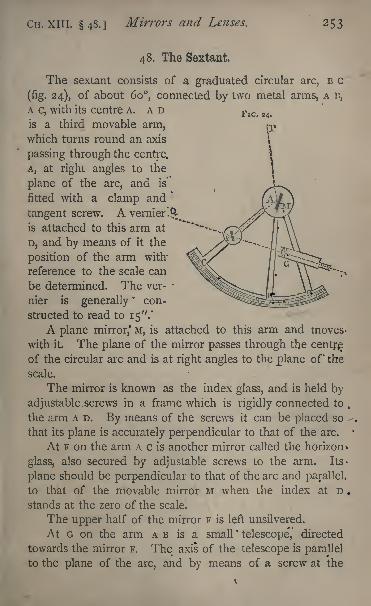
CH. XIII. 48.] Mirrors and Lenses. 253
48. The Sextant.
The sextant consists of a graduated circular arc, B c
(fig. 24), of about 60, connected by two metal arms, A n,
A c, with its centre A. ADis a third movable arm,which turns round an axis
passing through the centre.
A, at right angles to the
plane of the arc, and is
fitted with a clamp and*
tangent screw. A vernier '.^is attached to this arm at
D, and by means of it the
position of the arm with
reference to the scale can
be determined. The ver- *
nier is generally'
con-
structed to read to 15".'
A plane mirror,' M, is attached to this arm and moves -
with it. The plane of the mirror passes through the centr^of the circular arc and is at right angles to the plane of* the
scale.
The mirror is known as the index glass, and is held by
adjustable.screws in a frame which is rigidly connected to.
the arm A D. By means of the screws it can be placed so
that its plane is accurately perpendicular to that of the arc.'
At F on the arm A c is another mirror called the horizon *
glass, also secured by adjustable screws to the arm. Its-
plane should be perpendicular to that of the arc and parallel.
to that of the movable mirror M when the index at D .
stands at the zero of the scale.
The upper half of the mirror F is left unsilvered.
At G on the arm A B is a small'
telescope, directed
towards the mirror F. The axis of the telescope is parallel
to the plane of the arc, and by means of a screw at the
254 Practical Physics. [CH. XIII. 48.
back of the instrument the telescope can be moved at right
angles to this plane, so as to direct its axis towards the
silvered or unsilvered part of the horizon glass. This is placedin such a position that its normal bisects the angle A F G,
and hence a ray of light, parallel to the plane of the sextant,
travelling along A F, is reflected by the horizon glass parallel
to the axis of the telescope. Let P A be such a ray reflected
by the mirror M in direction A F, and suppose P to be somedistant object the position of which we wish to observe.
Let the telescope be so placed with reference to the planeof the instrument that light from a second distant object Q,
also travelling parallel to the plane of the sextant, can enter
the telescope through the unsilvered part of the glass F.
Then an observer, looking through the telescope, will see
the point Q directly, and the point P after reflexion at the
two mirrors M and F.
The telescope is fitted with cross-wires, and by altering
the position of the arm A D the image of P can be made to
coincide with that of Q in the centre of the field of view.
Let us suppose this adjustment made. Then by re-
flexion at the two mirrors the ray P A has been made to
coincide in direction with the ray Q F. Hence, the anglebetween P A and Q F is twice the angle between the two
mirrors. But when the index read zero the two mirrors were
parallel, so that twice the angle between the two mirrors is
twice the angle through which the arm and vernier have
been turned from zero.
In many instruments the graduations are numbered to
read as double of their real value;each degree is reckoned
as two degrees and so on, so that, if the instrument be in
adjustment, the reading of the vernier gives us directly the
angle between P A and Q F, that is, the angle which the two
distant points P and Q subtend at the observer's eye.
The requisite adjustments are :
(i) The plane of the index glass M should be at right
angles to that of the graduated ^areT
CH. XIII. 48.] Mirrors and Lenses. 255
(2) The plane of the horizon glass F should also be at
right angles to that of the arc.
(3) The axis of the telescope should be parallel to the
plane of the arc.
(4) The index and horizon glasses should be parallel
when the vernier reads zero.
We proceed to consider how to make these adjustments.The two glasses are held in their frames by screws, and
can be set in any position by altering these screws.
(1) Place the eye close to the index glass and look towards
the glass so as to see part of the arc c D and its reflexion,
meeting at the surface of the glass. If the two, the arc
and its image, appear to be in the same plane, then the
glass is perpendicular to that plane. If, however, the image
appears to rise out of the plane of the arc, the upper portionof the glass leans forward towards the eye, while if the
image appears to drop below the plane of the arc, the glass
leans back away from the eye. Adjust the screws till the
arc and its image appear to be in the same plane ; then the
plane of the glass is at right angles to that plane.
(2) To set the horizon glass. Hold the instrument so
as to view directly with the telescope some distant point a
star if possible. On turning the index arm round, an imageof the point, formed by reflexion at the two glasses, will
cross the field. If the two glasses be accurately parallel,
this image can be made to coincide exactly with the objectseen by the direct rays. If the plane of the horizon glass
be not at right angles to that of the arc, so that the two
mirrors can never be parallel, the image will appear to passto one side or the other of the object
By altering the adjusting screws of the horizon glass,
the image seen after two reflexions, and the object seen
directly, can be made to coincide in position. When this
is the case the two mirrors are strictly parallel, and the
horizon glass, therefore, is at right angles to the plane of
the arc.
256 Practical Physics. [CH. xiil. 48.
(3) To set the axis of the telescope parallel to the planeof the arc. For this it is necessary that the ring to which
the telescope is fixed should be capable of being movedabout an axis parallel to the line of intersection of its planewith that of the arc.
The eye-piece of the telescope is usually fitted with two
cross-wires, very approximately parallel to the plane of the
arc, and one wire at right angles to these, passing throughtheir middle points. The line joining the centre of the
object glass to the middle point of this wire is the optical
axis of the telescope. Hold the instrument so as to view
two distant points, such as two stars, the one directly and
the other by reflexion at the two glasses, and incline it to
the plane through the eye and the two stars in such a waythat the two images seen in the telescope appear to coincide
at the point in which the third wire cuts one of the two
parallel wires. Then, without moving the index glass, in-
cline the plane of the instrument until the image of the
star seen directly falls on the intersection of the third wire
and the other of the two parallel wires. If the image of the
second star again coincides with that of the first, it follows
that the optical axis of the telescope is parallel to the plane
of the arc;to make the two parallel the position of the
telescope with reference to the arc must be adjusted until
it is possible to observe such a coincidence.
(4) To set the two mirrors parallel when the vernier-index
reads zero. It will be found that one of the glasses with
its frame and adjusting-screws can be moved about an axis
at right angles to the plane of the arc. Set the vernier
to read zero and clamp it, and direct the telescope to some
distant point. If the two glasses are parallel this point,
and its image after reflexion at the two mirrors, will appear
to coincide. If they do not coincide they can be made
to do so supposing adjustments (i) and (2) have been
made by turning the movable mirror about the axis just
CH. XIII. 48.] Mirrors and Lenses. 257
spoken of, and when the coincidence is effected the mirrors
will be parallel, while the vernier reads zero.
Instead, however, of making this last adjustment, it is
better to proceed as follows to determine the index error of
the instrument
Direct the telescop'e to a distant point and turn the
index glass until the image of the point, after reflexion at the
two mirrors, coincides with the point itself as seen directly.
Clamp the vernier and read;
let the reading be a. It
the instrument were in perfect adjustment, the value of a
would be zero. Suppose, now, we find that when proceed-
ing to measure the angular distance between two distant
points, as already described, the scale and vernier reading
is (3, then the angular distance required is ft a. Generally
it gives less trouble to determine the index error than to set
the mirrors so that there is no such error.
It may, of course, happen that the value of a is nega-
tive in other words, that to bring a point and its imageinto coincidence we have to push the vernier back beyondthe zero of the scale
;for this reason the scale graduations
are continued beyond the zero.
It is important for accurate work that the two imageswhich are brought into coincidence should be about equally
bright. Now, the light from one has suffered two reflexions,
each of which somewhat diminishes its intensity. If, then,
the two distant objects are unequally bright, we should
choose the duller one as that to be viewed directly. Again,we have said already that the telescope can be moved in a
direction at right angles to the plane of the arc. In its
normal position the axis of the telescope will pass throughthe boundary between the silvered and unsilvered parts cf
the horizon glass. Half the object-glass will accordingly be
filled with direct light, half with reflected. If the direct
light is very much stronger than the reflected, we can, by
moving the telescope, still keeping its axis parallel to the
plane of the circle, place* it so that the reflected rays fill
S
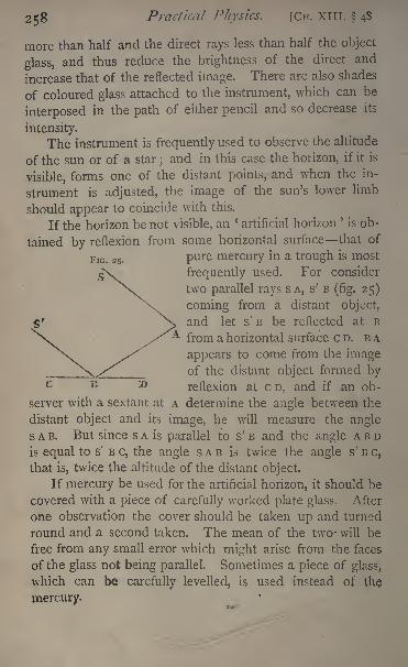
258 Practical Physics. [CH. XTTI. 48
more than half and the direct rays less than half the object
glass, and thus reduce the brightness of the direct and
increase that of the reflected image. There are also shades
of coloured glass attached to the instrument, which can be
interposed in the path of either pencil and so decrease its
intensity.
The instrument is frequently used to observe the altitude
of the sun or of a star; and in this case the horizon, if it is
visible, forms one of the distant points, and when the in-
strument is adjusted, the image of the sun's lower limb
should appear to coincide with this.
If the horizon be not visible, an'artificial horizon
'
is ob-
tained by reflexion from some horizontal surface that of
pure mercury in a trough is most
frequently used. For consider
two parallel rays SA, s' B(fig. 25)
coming from a distant object,
and let s' B be reflected at B
from a horizontal surface CD. B A
appears to come from the imageof the distant object formed by
c B ^ reflexion at CD, and if an ob-
server with a sextant at A determine the angle between the
distant object and its image, he will measure the angle
SAB. But since s A is parallel to s' B and the angle A B D
is equal to s' B c, the angle s A B is twice the angle s' B c,
that is, twice the altitude of the distant object.
If mercury be used for the artificial horizon, it should be
covered with a piece of carefully worked plate glass. After
one observation the cover should be taken up and turned
round and a second taken. The mean of the two* will be
free from any small error which might arise from the faces
of the glass not being parallel. Sometimes a piece of glass,
which can be carefully levelled, is used instead of the
mercury.
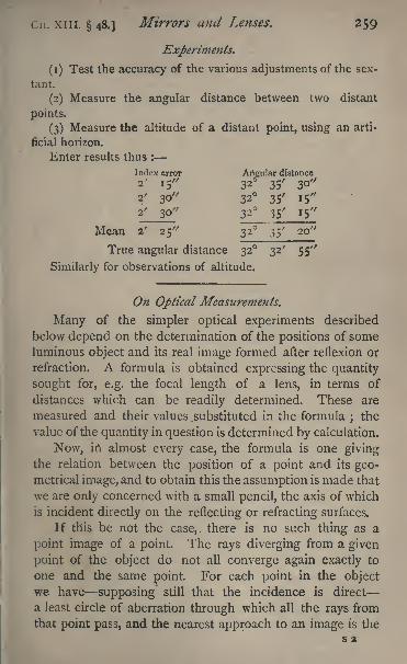
Cn. xni. 48.] Mirrors and Lenses. 259
Experiments.
(1) Test the accuracy of the various adjustments of the sex-
tant.
(2) Measure the angular distance between two distant
points.
(3) Measure the altitude of a distant point, using an arti-
ficial horizon.
Enter results thus :
Index error Artgular distance
2' 15" 32 35' 30"2/ 30
'/
32o
35/
I5"
2' 30" 32 35' 15"
Mean 2' 25" 32 35' 20
True angular distance 32 32' 55"
Similarly for observations of altitude.
On Optical Measurements.
Many of the simpler optical experiments described
below depend on the determination of the positions of someluminous object and its real image formed after reflexion or
refraction. A formula is obtained expressing the quantity
sought for, e.g. the focal length of a lens, in terms of
distances which can be readily determined. These are
measured and their values .substituted in the formula;the
value of the quantity in question is determined by calculation.
Now, in almost every case, the formula is one givingthe relation between the position of a point and its geo-metrical image, and to obtain this the assumption is made that
we are only concerned with a small pencil, the axis of which
is incident directly on the reflecting or refracting surfaces.
If this be not the case,, there is no such thing as a
point image of a point. The rays diverging from a given
point of the object do not all converge again exactly to
one and the same point. For each point in the object
we have supposing still that the incidence is direct
a least circle of aberration through which all the rays from
that point pass, and the nearest approach to an image is the*
260 Practical Physics. [CH. xm. 48.
figure formed by the superposition of all these least circles
of aberration, which will be a representation of the object,more or less blurred, and differing in position from the
geometrical image.
Now, frequently this happens with the images producedby the optical combinations with which we shall have to do.
The pencils which go to form the various images are not
small pencils incident directly, and the phenomena are thus
complicated by the effects of aberration.
Thus, for example, we may require the radius of a con-
cave mirror, three or four inches across and six or eightinches in radius
; or we may be experimenting with a lens
of an inch or so in diameter and only one or two inches in
focal length. In both these cases we should meet with
aberration difficulties. We shall see best how to allow for
this in each separate experiment.There is one measurement common to many optical experi-
ments, the mode of making which may best be described here.
Two objects the one may be a lens, the other a screen
on which an image is focussed are attached to the supportsof an optical bench described below. This is graduated,and the supports possibly are fitted with verniers
;at any
rate, there is a mark attached to them, the position of which,with reference to the scale of the bench, can be found.
We can thus find easily the distance between the two
fixed marks on the supports ; but suppose we require the dis-
tance between the screen and one face of the lens. To obtain
this we must know their positions with reference to the fixed
marks. Now, the apparatus is generally constructed so that
the central plane of the lens and the plane of the screen
respectively are in the same vertical plane as the marks
in question, so that, neglecting the thickness of the lens,
the distance between the marks is, as a matter of fact,
identical with the distance required. But for some purposes
this is not sufficiently accurate. We may, for example, wish
to consider the thickness of the lens in our measurements.
C ii. XIII. 48.]Mirrors and Lenses. 261
In this case, take a rod with two pointed ends, and mea-
sure carefully its length. Let it be a. Put one end against
the screen and move up the support carrying the other
surface, until this is in contact with the other end of the
rod. Let the distance between the marks on the supports,
as read at the same time by the scale and vernier, be b,
Then, clearly, if in any other position of the supports the
distance between the marks on them is c, the distance
between the surfaces is c+a b, for a was the distance
between them in the first position, and c b is the distance
by which it has been altered.
We may make the same measurement by the following
slightly different method which can be used convenientlyfor determining the distance between two objects measured
parallel to any fixed scale. Fix securely to the vernier of
the scale a stiff piece of wire, and bend it until its end
comes in contact with one of the objects in question, and
read the vernier. Now move the vernier with the wire
fixed relatively to it, along the scale, until the same end of the
wire comes in contact with the second object, then read
the vernier again. The difference between the two readings
is the distance required.
This will be found a convenient way in making the
measurements, described in 49, if the mirror can be fitted
to one of the supports of the optical bench.
Of course, if the distance required be only small, the
simplest method of all is to use a pair of compasses and
take it off along a finely divided scale.
49. Measurement of the Focal Length of a
Concave Mirror.
This may be obtained optically by means of the formula T
1 For the formulae required in this and the next chapter we mayrefer to Glazebrook, Physical Optics, chap. iv.
262 Practical Physics. [Cn. XIII. 49.
/ being the focal length, and r the radius of the surface, u
and v respectively the distances from the surface of an
object and its image ;u and v can be measured, and then r
or/calculated.In practice the following modification of the method
will be found most convenient.
It depends on the fact that when the image of an objectformed by concave mirror coincides with the object itself, then
the object is at the geometrical centre of the spherical surface.
Place a needle in a clip and set it in front of the
mirror; place the eye some distance further away from the
mirror than the needle. An inverted image of the needle
will be seen, unless the needle has been placed too close to
the mirror. Adjust the position of the needle relatively to
the mirror, so that the point of the image coincides with
the point of the needle. When this is the case the imagewill be of the same size as the object.
The adjustment can be made as finely as necessary,
either by moving the eye about and noting whether the
relative positions of image and needle vary, or by using a
strong magnifying lens, and noticing whether both needle
and image are in focus at the same time.
If the aperture of the mirror be very large, and its surface
not perfectly spherical, it may be impossible to see the
image when using the lens, in consequence of the aberration
of the rays from the outer portions of the surface. These
defects may, in some cases, be corrected by covering the
mirror with black paper, leaving at the centre only a small
hole, which may be either oblong or circular.
When the position of the needle has been carefully
adjusted, measure its distance from the reflecting surface bymeans of a pair of compasses and a scale, if the radius be
small, or by the method already described if the mirror be
fitted to the optical bench.
The result gives the length of the radius of the mirror
surface. Half of it is the focal length.
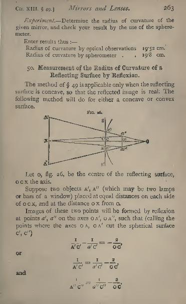
dr. XIII. 49.] Mirrors and Lenses. 263
Experiment. Determine the radius of curvature of the
given mirror, and check your result by the use of the sphero-
meter.
Enter results thus :
Radius of curvature by optical observations 19*52 cm.
Radius of curvature by spherometer . . 19*8 cm.
50. Measurement of the Kadius of Curvature of a
Reflecting Surface by Reflexion.
The method of 49 is applicable only when the reflecting
surface is concave, so that the reflected image is real: The
following method will do for either a concave or convex
surface.
FIG. 36.
Let o, fig. 26, be the centre of the reflecting surface,
o c x the axis.
Suppose two objects A', A" (which may be two lampsor bars of a window) placed at equal distances on each side
of o c x, and at the distance o x from o.
Images of these two points will be formed by reflexion
at points a', a" on the axes o A', o A", such that (calling the
points where the axes o A, o A' cut the spherical surface
c', c")I I _ _ 2
af~d~ oc1
or
and
i
A'C'
I
a'cf
OC
264 Practical Physics. [Cu. XIII. 50.
Now, the points being very distant, and therefore c' A' very
nearly equal to c x, we may assume that the straight line
a' a" cuts the axis o c x at a point x where
-L---L--1cx cx oc
and for the size of the image, we have
A'A"OX
Hence, if c x = A, o c r, A' A" = L, c x = x, and a' a'1 \
we get from (i)
ii_ _ 2 , v
Hencei i i i
. r+A_r xA X '
x r x' '
A~~r+A 5
and
L A
From these two equations
T _ Ar2\ + r
Place a small, finely divided scale S s' immediately in
front of the reflecting surface (but not so as to prevent all
the light falling upon it)i.e. place it horizontally to cover
nearly half the reflecting surface, and observe the images
Cn. XIII. 50.] Mirrors and Lenses. 26$
a', a" and the scale s s' by means of a telescope placed so
that its object-glass shall be as nearly as possible in the
middle of the line joining A A'; we may with sufficient
accuracy suppose the centre of the object-glass to be at the
point x. Join x a, xa' and let the lines x a,xa' ! cut the
scale s s' in L' and L", and let / denote the length L' L" of
the scale intercepted by them.
Then we get
/XL7 A , . , x
x=
,
=(approximately),A x a
A+ r
or
or
The formula proved above refers to a convex surface;
if the surface be concave we can find similarly the equation
r= 2A/
L-f 2 /'
To make use of this method to find the radius of curva-
ture of a surface, place the surface opposite to, but at somedistance from, a window. Then place horizontally a straightbar of wood, about half a metre in length between the
surface and the window, fixing it approximately parallel to
the surface, and at such a height that its reflexion in the
surface is visible to an eye placed just below the bar, and
appears to cross the middle part of the surface. Fix a
telescope under the centre of the bar, with its object-glass
266 Practical Physics. [CH. XIII. 50.
in the same vertical plane as the bar, and focus it so as to
see the image reflected in the surface.
It is best that the whole of the bar should be seen re-
flected in the surface. If this cannot be secured, two well-
defined marks, the reflected images of which can be clearly
seen, should be made on the bar. These may be obtained
by fixing two strong pins into the upper edge, or by
laying on it two blocks of wood with clearly defined edges.
In any case the reflected image should appear in the
telescope as a well-marked dark object against the bright
background of the reflexion of the window. If it be more
convenient to work in a dark room, arrangements must be
made to illuminate the bar brightly, so that its reflexion
may appear light against a dark background.Now place against the reflecting surface a finely gra-
duated scale one divided to half-millimetres or fiftieths
of an inch will do arranging it so that one edge of the
image of the bar is seen against the divided edge of the
scale. If the curvature of the surface be considerable, and
the magnifying power of the telescope not too great, the
scale will be fairly in focus at the same time as the imageof the bar. At any rate, it will be possible to read the
graduations of the scale which the image of the bar
appears to cover. This gives us the length / of the
above formula. Measure the length of the bar or the
distance between the two marks this we call L;and
measure with a tape the distance between the reflecting
surface and the centre of the object-glass of the telescope
this gives A.
Then the formula gives us r,
In some cases it may be possible to see more than one
reflected image of the bar; e.g. if a reflecting surface be
one surface of a lens, we may have a reflexion from the
back surface as well as from the front. A little consideration
enables us to choose the right image. Thus, if the first
surface is convex, the reflected image will be erect and will,
CH. XIII. 50.] Mirrors and Lenses. 267
therefore, appear inverted if we are using an astronomical
telescope.
Experiment. Determine the radius of the given surface,
checking the result by the use of the spherometer.
Enter results thus :
Surface ConvexA= 175-6 cm,
L = 39-4 cm.
/= 2-06 cm.
r= 20-5 cm.
Value found by spherometer 20-6 cm.
Measurement of Focal Lengths of Lenses.
The apparatus generally employed to determine the focal
length of a lens is that known as the optical bench.
It consists simply of a horizontal scale of considerable
length, mounted on a substantial wooden beam, along which
upright pieces can slide, and to these are severally attached
the lens, the luminous object, and a screen on which the
image formed by the lens is received. These sliding-pieces
carry verniers, by which their position with reference to the
scale can be determined. The position of each face of the
lens relatively to the zero of the vernier is known or can
be found as described on p. 261.
51. Measurement of the Focal Length of a ConvexLens. First Method.
For this purpose a long bar of wood, is employed, carry-
ing at one end a ground-glass screen, fixed at right anglesto the length of the bar. A stand, in which the lens
can conveniently be fixed with its axis parallel to the lengthof the bar, slides along it, and the whole apparatus is port-
able, so that it can be pointed towards the sun or any other
distant object.
Place the lens in the stand and withdraw to a darkcorner of the laboratory ; point the apparatus to a distant
268 Practical Physics. [Cn. XIII. 5!.
well-defined object a vane seen through a window againstthe sky is a good object to choose if the sun be not visible
and slide the lens along the bar until a sharply defined imageof the object is formed upon the ground glass. Since the
object is very distant, the distance of the lens from the screen
is practically equal to the focal length, and can be measured
either with a tape or by means of graduations on the bar itself.
The observation should, of course, be made more than
once, and the mean of the measurements taken.
52. Measurement of the Focal Length of a Convex
Lens. Second Method.
Mount on one of the stands of the bench a diaphragmwith a hole in it across which two fine threads are stretched,
or, if more convenient, a piece of fine wire grating, or a
pin in a vertical position with its point about the centre of
the hole. Place a light behind the hole, taking care that
the brightest part of the light is level with the hole and
exactly behind it, while the light is as close to the hole as
may be.
In the second stand place the lens, fixing it so that its
centre is on the same level as that of the hole in the dia-
phragm, while its axis is parallel to the length of the bench.
In the third stand fix an opaque white screen;a piece
of ground glass or unglazed paper is most suitable. For
the present purpose the objects can generally be fixed on
their respective stands so as to occupy with sufficient accu-
racy the same relative positions with regard to the zeros of
the verniers, and thus the distances between the different
objects in question can be obtained at once, by reading the
verniers and subtracting.
If the distance between the first and third stand be
more than four times the focal length of the lens, the latter
can be placed so that there is formed on the screen a dis-
tinct image of the object in the first stand. Move the
stand carrying the lens till this is the case. Then measure
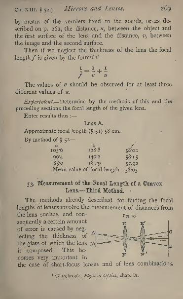
Cn. XIII. 52.]Mirrors and Lenses. 269
by means of the verniers fixed to the stands, or as de-
scribed on p. 261, the distance, u> between the object and
the first surface of the lens and the distance, ?>, between
the image and the second surface.
Then if we neglect the thickness of the lens the focal
length/ is given by the formula 1
' = 1 + 1/ v u
The values of v should be observed for at least three
different values of u.
Experiment. Determine by the methods of this and the
preceding sections the focal length of the given lens.
Enter results thus :
Lens A.
Approximate focal length ( 51) 58 cm.
By method of 5211 Z> f
105-6 128-8 58-02
99-4 140-1 58-15
85-0 181-9 57.92
Mean value of focal length 58*03
53. Measurement of the Focal Length of a ConvexLens. Third Method.
The ^methods already described for finding the focal
lengths of lenses involve the measurement of distances from
the lens surface, and con- FlG< 2?
sequently a certain amount
of error is caused by neg-
lecting the thickness of
the glass of which the lens
is composed. This be-
comes very important in
the case of short-focus lenses and of lens combinations.
1Glazebrook, Physical Optics, chap. iv.
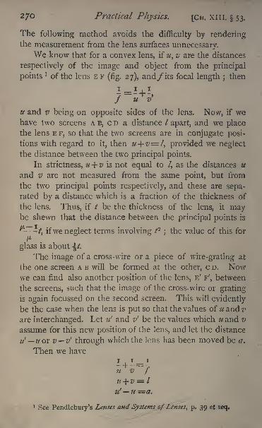
270 Practical Physics. [CH. XI 1 1. 53.
The following method avoids the difficulty by renderingthe measurement from the lens surfaces unnecessary.
We know that for a convex lens, if u, v are the distances
respectively of the image and object from the principal
points* of the lens E F
(fig. 27), and/ its focal length ; then
7=1+ -'
/ u v
u and v being on opposite sides of the lens. Now, if wehave two screens A B, c D a distance / apart, and we placethe lens E F, so that the two screens are in conjugate posi-
tions with regard to it, then u+ v= t, provided we neglect
the distance between the two principal points.
In strictness, u+ v is not equal to /, as the distances u
and v are not measured from the same point, but from
.the two principal points respectively, and these are sepa-rated by a distance which is a fraction of the thickness of
the lens. Thus, if / be the thickness of the lens, it maybe shewn that the distance between the principal points is
^^i/, ifwe neglect terms involving P \the value of this for
pglass is about /.
The image of a cross-wire or a piece of wire-grating at
the one screen A B will be formed at the other, c D. Nowwe can find also another position of the lens, E' F', between
the screens, such that the image of the cross-wire or grating
is again focussed on the second screen. This will evidently
be the case when the lens is put so that the values of u and?'
are interchanged. Let ?/' and v' be the values which u and v
assume for this new position of the lens, and let the distance
'_ or v v' through which the lens has been moved be a.
Then we have
1 + 1=1u v fti+ v = l
u' u =#.
1 See Pendlebury's Lenses and Systems of Lenses, p. 39 et seq.
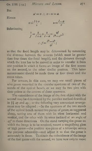
CH. XIII. 53.]Mirrors and Lenses. 271
But
rf = v ', vu = a.
Hence
Substituting
so that the focal length may be determined by measuringthe distance between the screens (which must be greater
than four times the focal length), and the distance throughwhich the lens has to be moved in order to transfer it from
one position in which it forms an image of the first screen
on the second, to the other similar position. This latter
measurement should be made three or four times and the
mean taken.
For screens, in this case, we may use small pieces of
wire gauze mounted in the circular apertures of two of the
stands of the optical bench, or we may fix two pins with
their points at the centres of these apertures.
The coincidence of the image of the first object with the
second may be determined by the parallax method described
in 47 4and 49 ;
or the following very convenient arrange-
ment may be adopted : In the apertures of the two stands
of the optical bench mount two pieces of gauze, as suggested
above, setting one of them with its wires horizontal and
vertical, and the other with its wires inclined at an angle of
45 to these directions. On the stand carrying the gauze on
which the image is to be received, mount a magnifying glass
of high power the positive eye-piece of a telescope serves
the purpose admirably and adjust it so that the gauze is
accurately in focus. To obtain the coincidence of the imageof the first gauze with the second, we have now only to move
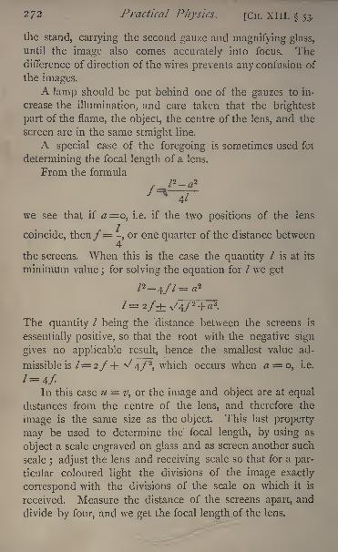
2/2 Practical Physics. [Cn. XIII. 53.
the stand, carrying the second gauze and magnifying glass,
until the image also comes accurately into focus. Thedifference of direction of the wires prevents any confusion of
the images.
A lamp should be put behind one of the gauzes to in-
crease the illumination, and care taken that the brightest
part of the flame, the object, the centre of the lens, and the
screen are in the same straight line.
A special case of the foregoing is sometimes used foi
determining the focal length of a lens.
From the formula
we see that if #=o, i.e. if the two positions of the lens
coincide, then/= -, or one quarter of the distance between4
the screens. When this is the case the quantity / is at its
minimum value;for solving the equation for / we get
The quantity / being the distance between the screens is
essentially positive, so that the root with the negative sign
gives no applicable result, hence the smallest value ad-
missible is 1=2f + >/4/2
,which occurs when a = o, i.e.
l= 4/.In this case u v, or the image and object are at equal
distances from the centre of the lens, and therefore the
image is the same size as the object. This last property
may be used to determine the focal length, by using as
object a scale engraved on glass and as screen another such
scale; adjust the lens and receiving scale so that for a par-
ticular coloured light the divisions of the image exactly
correspond with the divisions of the scale on which it is
received. Measure the distance of the screens apart, and
divide by four, and we get the focal length of the lens.
CH. xrn. 53.] Mirrors and Lenses. 273
A magnifying glass should be used to observe the image,and the observation, as usual, repeated several times.
We know that the focal length of a lens depends on the
refractive index of the material of which it is composed,and that this is different for the different rays of the spectrum,so that we should expect to get different values for the focal
length by illuminating the object with differently coloured
rays. The methods just described for finding the focal
length enable us to do this by placing between the lampand the object plates of variously coloured glass, red, green,
or blue, for example. The position of the receiving 'screen
and consequent value of the focal length will differ in the
three cases.
Observations with the blue glass will present, perhaps,the greatest difficulty, for most blue glasses let throughsome red light as well, so that two images are formed a
little way apart, one for the blue and the other for the red
light. If, then, we are using the wire grating as object,
the spaces, when focussed for blue light, will appear blue
in the image and the wires red, while if we use the same
glass in finding the focal length for the red light, we must
focus so that the wires look blue and the spaces red.
It is quite easy to adapt the method of this section for
finding accurately the focal length of the lens, taking into
account the thickness, as follows :
Since u and v are measured from the principal points, and
the distance between these is very nearly^~ I
/, we have
or
and
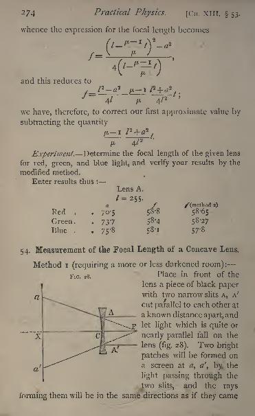
274 Practical Physics. [Cn. XIII. 53.
whence the expression for the focal length becomes
f=
and this reduces to
/=
V-
we have, therefore, to
subtracting the quantity
4/ /* 4/2
correct our first approximate value by
Experiment. Determine the focal length of the given lens
for red, green, and blue light, and verify your results by the
modified method.
Enter results thus :
Lens A.
Red ,
Green.
Blue .
70-5
737
75'8
/58-8
58*4
58-1
/"(method 2)
58-65
58-27
57-8
54. Measurement of the Focal Length of a Concave Lens.
Method i (requiring a more or less darkened room):
FlG . 2g .Place in front of the
lens a piece of black paperwith two narrow slits A, A'
cut parallel to each other at
a known distance apart, and
let light which is quite or
nearly parallel fall on the
lens (fig. 28). Two bright
patches will be formed on
a screen at a, a', by, the
light passing through the
two slits, and the rays
forming them will be in the same directions as if they came
a
CH. XIII. 54.] Mirrors and Lenses. 275
from the principal focus F of the lens. If then we measure
a a' and c x, and if c F =f, we have
/ _AA'/+cx a a
1 '
from which / can be found. The distance between the
centres of the bright patches can be measured with a pair of
compasses and a finely divided scale, or by using a scale as
the screen on which the light falls.
In consequence of the indistinctness of the bright
patches, this is only a very rough method of determiningthe focal length.
Method 21
The second method consists in placing in contact with
the given concave lens a convex lens sufficiently powerfulto make a combination equivalent to a convex lens. Let
the focal length (numerical) of the concave lens be f, that
of the auxiliary convex lens /, and that of the com-
bination F.
Then
The values of F and f can be found by one of the
methods described for convex lenses.
In selecting a lens with which to form the combina-
tion it should be noticed that, if F and/' differ only slightly,
say by i centimetre, an error of i millimetre in the deter-
mination of each, unless the errors happen to be in the same
direction, will make a difference of one- fifth in the result.
The auxiliary lens should therefore be chosen to make the
difference F /' as large as possible i.e. the concave lens
should with the convex produce a combination nearly equiva-
lent to a lens with parallel faces, so that - may be veryj /
nearly equal to7/
.
f T2
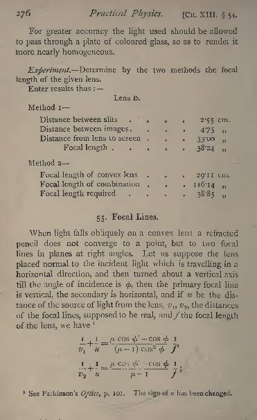
276 Practical Physics. [CH. XIII. 54.
For greater accuracy the light used should be allowed
to pass through a plate of coloured glass, so as to rendei it
more nearly homogeneous.
Experiment. Determine by the two methods the focal
length of the given lens.
Enter results thus :
Lens D.
Method i
Distance between slits . . . . 2-55 cm.
Distance between images.... 475Distance from lens to screen . . . 33-00
Focal length ..... 38-24 ,,
Method 2
Focal length of convex lens . . . 29-11 cm.
Focal length of combination . . . 116-14
Focal length required . . . 38-85
55. Focal Lines,
When light falls obliquely on a convex lens a refracted
pencil does not converge to a "point, but to two focal
lines in planes at right angles. Let us suppose the lens
placed normal to the incident light which is travelling in a
horizontal direction, and then turned about a vertical axis
till the angle of incidence is<f>,
then the primary focal line
is vertical, the secondary is horizontal, and if u be the dis-
tance of the source of light from the lens, z/,, z/2 ,the distances
of the focal lines, supposed to be real, and/ the focal length
of the lens, we have ]
_i_, i_ _ /'-cos <' - cos
<fti
#! U (fl l) COS2<ft /'
I If.L
COS(/>' COS
<ftI
V2 U /A I /'
1 See Parkinson's 0/>ticst p. 101. The sign of u has been changed.
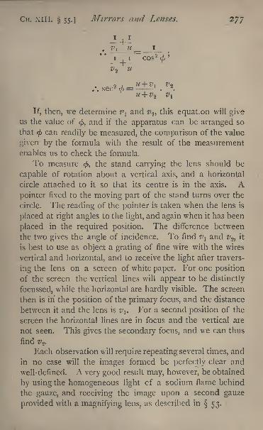
CH. xill. 55.] Mirrors and Lenses. 277
7', U_ I
I I COS 2<f>
'
.'. sec'2
d> = 7' 2
If, then, we determine i\ and z> 2 ,this equation will give
us the value of</>,
and if the apparatus can be arranged so
that<f>
can readily be measured, the comparison of the value
given by the formula with the result of the measurement
enables us to check the formula.
To measure <, the stand carrying the lens should be
capable of rotation about a vertical axis, and a horizontal
circle attached to it so that its centre is in the axis. Apointer fixed to the moving part of the stand turns over the
circle. The reading of the pointer is taken when the lens is
placed at right angles to the light, and again when it has been
placed in the required position. The difference between
the two gives the angle of incidence. To find i\ and z>2 ,it
is best to use as object a grating of fine wire with the wires
vertical and horizontal, and to receive the light after travers-
ing the lens on a screen of white paper. For one position
of the screen the vertical lines will appear to be distinctly
focussed, while the horizontal are hardly visible. The screen
then is in the position of the primary focus, and the distance
between it and the lens is #,. For a second position of the
screen the horizontal lines are in focus and the vertical are
not seen. This gives the secondary focus, and we can thus
find #2 .
Each observation will require repeating several times, and
in no case will the images formed be perfectly clear and
well-defined. A very good result may, however, be obtained
by using the homogeneous light cf a sodium flame behind
the gauze, and receiving the image upon a second gauze
provided with a magnifying lens, as described in 53.
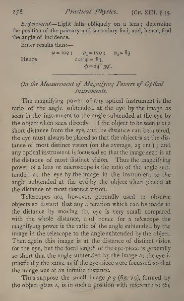
278 Practical Physics. [CH. XIII. 55.
Experiment. Light falls obliquely on a lens;
determine
the position of the primary and secondary foci, and, hence, find
the angle of incidence.
Enter results thus:
Hence cos9
$ --83,
</>= 24 39'.
On tJie Measurement of Magnifying Powers of OpticalInstruments.
The magnifying power of any optical instrument is the
ratio of the angle subtended at the eye by the image as
seen in the instrument to the angle subtended at the eye bythe object when seen directly. If the object to be seen is at a
short distance from the eye, and the distance can be altered,
the eye must always be placed so that the object is at the dis-
tance of most distinct vision (on the average, 25 cm.) ;and
any optical instrument is focussed so that the image seen is at
the distance of most distinct vision. Thus the magnifying
power of a lens or microscope is the ratio of the angle sub-
tended at the eye by the image in the instrument to the
angle subtended at the eye by the object when placed at
the distance of most distinct vision.
Telescopes are, however, generally used to observe
objects so distant that any alteration which can be made in
the distance by moving the eye is very small comparedwith the whole distance, and hence for a telescope the
magnifying power is the ratio of the angle subtended by the
image in the telescope to the angle subtended by the object.
Then again this image is at the distance of distinct vision
for the eye, but the focal length of the eye-piece is generally
so short that the angle subtended by the image at the eye is
practically the same as if the eye-piece were focussed so that
the image was at an infinite distance.
Thus suppose the small image p q (fig. 29), formed by
the object-glass A, is in such a position with reference to the
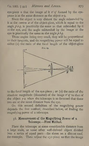
XIII. 55.] Mirrors and Lenses. 279
eye -piece B that the image of it P' Q' formed by the eye-
piece is at the same distance as the object P Q.
Since the object is very distant the angle subtended byit at the centre a of the object-glass, which is equal to the
angle / a q, is practically the same as that subtended by it
at the eye, and the angle subtended by the image at the
eye is practically the same as the angle pbq.These angles being very small, they will be proportional
to their tangents, and the magnifying power will be equal to
either (i) the ratio of the focal length of the object-glass
FIG. 29.
to the focal length of the eye-piece ; or (2) the ratio of the
absolute magnitude (diameter) of the image P' Q' to that of
the object P Q when the telescope is so focussed that these
two are at the same distance from the eye.
On this second definition of the magnifying power
depends the first method, described below, of finding the
magnifying power of a telescope.
56. Measurement of the Magnifying Power of a
Telescope. First Method.
Place the telescope at some considerable distance from
a large scale, or some other well-defined object divided
into a series of equal parts the slates on a distant roof,
for example, Then adjust the eye-piece so that the image
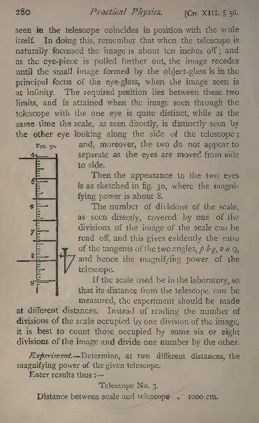
280 Practical Physics. [CH. XIII. 56.
seen in the telescope coincides in position with the scale
itself. In doing this, remember that when the telescope is
naturally focussed the image is about ten inches off ;and
as the eye-piece is pulled further out, the image recedes
until the small image formed by the object-glass is in the
principal focus of the eye-glass, when the image seen is
at infinity. The required position lies between these two
limits, and is attained when the image seen through the
telescope with the one eye is quite distinct, while at the
same time the scale, as seen directly, is distinctly seen bythe other eye looking along the side of the telescope ;
FIG. 30. and, moreover, the two do not appear to
separate as the eyes are moved from side
to side.
Then the appearance to the two eyes
is as sketched in fig. 30, where the magni-
fying power is about 8.
The number of divisions of the scale,
as seen directly, covered by one of the
divisions of the image of the scale can be
read off, and this gives evidently the ratio
tof
the tangents of the two angles,/ b q, p a Q,
and hence the magnifying power of the
telescope.
If the scale used be in the laboratory, so
that its distance from the telescope can be
measured, the experiment should be madeat different distances. Instead of reading the number of
divisions of the scale occupied by one division of the image,it is best to count those occupied by some six or eight
divisions of the image and divide one number by the other.
Experiment. Determine, at two different distances, the
magnifying power of the given telescope.
Enter results thus :
Telescope No. 3.
pistance between scale and telescope jooo cm,
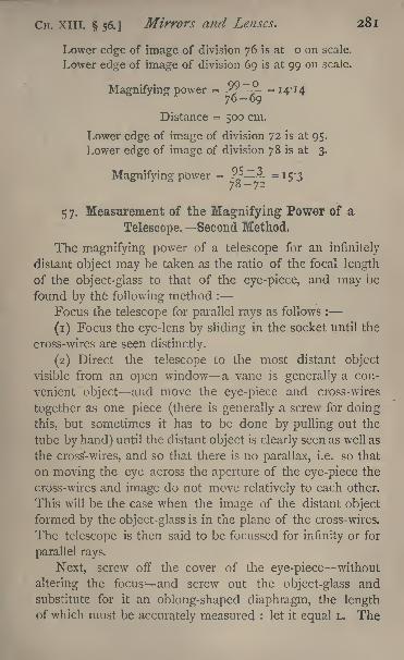
CH. XIII. 56.] Mirrors and Lenses. 281
Lower edge of image of division 76 is at o on scale.
Lower edge of image of division 69 is at 99 on scale.
Magnifying power = - = I 4' I4
Distance = 500 cm.
Lower edge of image of division 72 is at 95.
Lower edge of image of division 78 is at 3.
Magnifying power = 95^
3_ _l^
57. Measurement of the Magnifying Power of a
Telescope. Second Method.
The magnifying power of a telescope for an infinitely
distant object may be taken as the ratio of the focal length
of the object-glass to that of the eye-piece, and may be
found by the following method :
Focus the telescope for parallel rays as follows :
(1) Focus the eye-lens by sliding in the socket until the
cross-wires are seen distinctly.
(2) Direct the telescope to the most distant object
visible from an open window a vane is generally a con-
venient object and move the eye-piece and cross -wires
together as one piece (there is generally a screw for doing
this, but sometimes it has to be done by pulling out the
tube by hand) until the distant object is clearly seen as well as
the cross-wires, and so that there is no parallax, i.e. so that
on moving the eye across the aperture of the eye-piece the
cross-wires and image do not move relatively to each other.
This will be the case when the image of the distant object
formed by the object-glass is in the plane of the cross-wires.
The telescope is then said to be focussed for infinity or for
parallel rays.
Next, screw off the cover of the eye-piece without
altering the focus and screw out the object-glass andsubstitute for it an oblong-shaped diaphragm, the lengthof which must be accurately measured : let it equal L, The
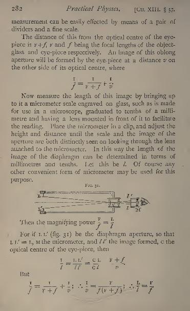
282 Practical Physics [Cu. XIII. 57.
measurement can be easily effected by means of a pair of
dividers and a fine scale.
The distance of this from the optical centre of the eye-
piece is F+/ F and / being the focal lengths of the object-
glass and eye-piece respectively. An image of this oblong
aperture will be formed by the eye- piece at a distance v on
the other side of its optical centre, where
Now measure the length of this image by bringing upto it a micrometer scale engraved on glass, such as is madefor use in a microscope, graduated to tenths of a milli-
metre and having a lens mounted in front of it to facilitate
the reading. Place the micrometer in a clip, and adjust the
height and distance until the scale and the image of the
aperture are both distinctly seen on looking through the lens
attached to the micrometer. In this way the length of the
image of the diaphragm can be determined in terms of
millimetres and tenths. Let this be /. Of course anyother convenient form of micrometer' may be used for this
purpose.FIG. 31.
Then the magnifying power 2 7
For if L i/ (fig. 31) be the diaphragm aperture, so that
L L' = L, M the micrometer, and //' the image formed, c the
optical centre of the eye-piece, then
i _ i- T/ _ c_^F +/
7~77
:~c7
'
v
But
I _ F.L _ F
"' 7
CM. XITT. 57.] Mirrors and Lenses. 283
In measuring the length of the image by the micro-
meter scale, the aperture should not be too brightly illu-
minated, or the image may be blurred and indistinct. The
telescope should on this account be pointed at a sheet of
grey filter-paper or other slightly illuminated uniform sur-
face, giving just light enough for reading the micrometer scale.
Experiment. Determine the magnifying power of the
given telescope.
Enter results thus:
Telescope No. 2.
Length of aperture . . . . 2*18 cm.
Length of image .... -16 cm.
Magnifying power . 13-6
58. Measurement of the Magnifying Power of a Lens
or of a Microscope.
A lens or microscope is used for the purpose of viewing
objects whose distance from the eye is adjustable, and in
such cases the magnifying power is taken to be the ratio of
the angle subtended at the eye by the image as seen in the
instrument to the angle subtended at the eye by the object
when placed at the distance of most distinct vision (generally
25 cm.). The instrument is supposed to be focussed so
that the image appears to be at the distance of most distinct
vision.
The method described for a telescope in 56 is applicable,
with slight alteration, to the case of a lens or microscope.
The instrument is focussed on a finely divided scale;one
eye looks at the magnified image while the other looks at
another scale placed so as to be 25 cm. away from the eye.
and to appear to coincide in position with the image of the
first scale viewed through the instrument. Suppose the two
scales are similarly graduated, and that ,r divisions of the
magnified scale cover x divisions of the scale seen directly,
then the magnifying power is x/#. If the two scales be not
284 Practical Physics. [Cn. XIII. 58.
similarly divided and it is often more convenient that theyshould not be so a little consideration will shew how the
calculation is to be made. Thus, if the magnified scale be
divided into ;;zths of an inch, and the unmagnified one into
ths,and if x divisions of the magnified scale cover x un-
magnified divisions, then the magnified image of a length of
x\m inches covers an unmagnified length of x/# inches, and
the magnifying power is therefore mx.jnx.The following modification of the method gives the two
images superposed when only one eye is used : Mount a
camera-lucida prism so that its edge passes over the centre
of the eye-lens of the microscope. Then half the pupil of
the eye is illuminated by light coming through the micro-
scope, and the other half by light reflected at right angles bythe prism. If a scale be placed 25 cm. away from the prism,
its image seen in the camera-lucida may be made to coin-
cide in position with the image of the scale seen by the other
half of the pupil through the microscope.
To make this experiment successful, attention must be
paid to the illumination of the two scales. It must be re-
membered that magnifying the scale by the microscopereduces proportionately the brightness of the image. Thus
the magnified scale should be as brightly illuminated as
possible, and the reflected scale should be only feebly illumi-
nated. It should also have a black screen behind it, to cut
off the light from any bright object in the background.
A piece of plane unsilvered glass set at 45, or a mirror
with a small piece of the silvering removed, may be used in-
stead of the camera lucida prism.
The magnifying power of a thin lens may be calculated
approximately from its focal length. The eye being placed
close to the lens, we may take angles subtended at the centre
of the lens to be equal to angles subtended at the eye.
Now a small object of length / placed at a distance of 25 cm.
subtends an angle whose measure may be taken to be 7/25.
When the lens is interposed the image.,is to be at a distance
CH. XIII. 58.] Mirrors and Lenses. 285
of 25 cm., and the distance between the object and eye
must be altered ; the object will therefore be at a distance u
where
i_^__i25~7'
The angle subtended by the image is similarly measured
by its length divided by 25, and this is equal to //*/, or
25
Thus the magnifying power is
or
A microscope with a micrometer scale in the eye-piece is
sometimes used to measure small distances. We may there-
fore be required to determine what actual length corresponds,
when magnified, to one of the divisions of the micrometer
scale in the eye-piece.
For this purpose place below the object-glass a scale
divided, say, to tenths of a millimetre, and note the number
of divisions of the eye-piece scale which are covered byone division of the object scale seen through the micro-
scope ;let it be a. Then each division of the eye-piece
scale corresponds clearly to i/a of one-tenth of one milli-
metre, and an object seen through the microscope which
appears to cover b of these eye-piece divisions is in length
equal to b\a of one-tenth of a millimetre.
If \vc happen to know the value of the divisions of the
eye-piece scale we can get from this the magnifying powerof the object-glass itself, in the case in which the microscopeis fitted with a Ramsden's or positive eye-piece, and thence,
286 Practical Pliysics. [Cn. XIII. 58.
on determining the magnifying power of the eye-piece, find
that of the whole microscope. For if m{be the magnifying
power of the object-glass, m>2 that of the eye-piece, then
that of the whole microscope is in\ xm 2 .
Thus, if the eye-piece scale is itself divided to tenths
of millimetres, since one-tenth of a millimetre of the object
scale appears to cover a tenths of a millimetre of the eye-
piece scale, the magnifying power of the object-glass is a.
If, on the other hand, the microscope is fitted with a
Huyghens or negative eye-piece, then the eye-piece scale
is viewed through only the second or eye lens of the eye-
piece, while the image of the object scale, which appearsto coincide with it, is that formed by refraction at the
object-glass and the first or field lens of the eye-piece ;the
magnifying power determined as above is that of the com-
bination of object-glass and field lens. To determine the
magnifying power for the whole microscope, in this case
we must find that of the eye-lens and multiply the two
together.
It should be noticed that the magnifying power of a
microscope depends on the relative position of the object-
glass and eye-piece. Accordingly, if the value of the mag-
nifying power is to be used in subsequent experiments, the
focussing of the object viewed must be accomplished by
moving the whole instrument.
Experiment. Determine by both methods the magnifying
power of the given microscope.
Enter the results thus:
First method. Scale viewed through microscope graduatedto half-millimetres. Scale viewed directly graduated to milli-
metres.
Three divisions of scale.seen through microscope cover 129of scale seen directly.
Magnifying power =1^2
= 86.
Cn. XIII. 58.] Mirrors and Lenses. 287
Second method. One division of eye-piece scale = '$ mm.Three divisions of scale viewed cover I4'57 divisions of eye-
piece scale.
Magnifying power of eye-piece 18.
.*. Magnifying power of microscope = --L-L' x 18 = 87*4.
59. The Testing of Plane Surfaces.
The planeness of a reflecting surface can be tested more
accurately by optical means than in any other way.
The method depends on the fact that a pencil of parallel
rays remains parallel after reflexion at a plane surface.
To make use of this, a telescope is focussed on a very
distant object so distant that the rays coming from it maybe regarded as parallel. The surface to be tested is then
placed so that some of the parallel rays from the distant
object fall on it and are reflected, and the telescope is
turned to receive the reflected rays to view, that is, the
reflected image. If the surface be plane, the reflected rays
will be parallel and the image will be as far away as the
object. When viewed through the telescope, then, it will
be seen quite sharp and distinct. If, on the other hand,the surface be not plane, the rays which enter the object-
glass will not be parallel, and the image seen in the tele-
scope will be blurred and indistinct.
We can thus easily test the planeness of a surface. If
the surface is found to be defective, the defect may arise in
two ways :
(a) From the surface being part of a regular reflecting
surface a sphere or paraboloid, for example and not
plane.
In this case a distinct image of the distant object is
formed by reflexion at the surface ; but, the surface not
being plane, the pencils forming the image will not be pa-
rallel, and therefore, in order to see it, we must alter the
288 Practical Physics. [CH. XIII. 59.
focussing of the telescope. We shall shew shortly how, by
measuring the alteration in the position of the eye-piece of
the telescope, we can calculate the radius of curvature of
the surface.
() In consequence of the general irregularity of the
surface. In this case we cannot find a position of the eye-
piece, for which we get a distinct image formed the best
image we can get will be ill-defined and blurred. We maysometimes obtain a definite image by using only a small
part of the reflecting surface, covering up the rest. This mayhappen to give regular reflexion, and so form a good image.
To test roughly the planeness of a surface or to measure
its curvature, if the latter be considerable, an ordinary ob-
serving telescope may be used.
Focus it through the open window on some distant,
well-defined object. A vane, if one be visible, will be found
convenient. Place the surface to reflect some of the rays from
the distant object at an angle of incidence of about 45, and
turn the telescope to view the reflected image.
If the image is in focus, the surface is plane.
If by altering the focus we can again get a well-defined
image, the surface reflects regularly, and is a sphere or
something not differing much from a sphere ;if the image
can never be made distinct and clear, the surface is irregular.
Let us suppose we find that by a slight alteration in the focus
we can get a good image, we shall shew how to measure the
radius of curvature of the surface. To do this accurately,
we require a rather large telescope with an object-glass of
considerable focal length, say about i metre.
It will be better, also, to have a collimator. This con-
sists of a tube with a narrow slit at one end of it and a
convex lens at the other, the focal length of the lens being
the length of the tube; the slit is accordingly in the princi-
pal focus of the lens, and rays of light coming from it are
rendered parallel by refraction at the lens. Sometimes a
tube carrying the slit slides in one carrying the lens, so
that the distance between the two can^be adjusted
CH. xill. 59.] Mirrors and Lenses. 289
We shall suppose further that there is a distinct markon the telescope tube and another on the sliding tube to
which the eye-piece is attached. We shall require to mea-sure the distance between these marks
;the line joining
them should be parallel to the axis of the telescope. The
telescope should also be furnished with cross-wires.
Focus the eye-piece on the cross-wires. Turn the tele-
scope to the distant object and adjust the focussing screw,
thus moving both eye-piece and cross-wires relatively to the
object-glass, until the object is seen distinctly and without
any parallax relatively to the cross-wires. To determine
when this is the case move the eye about in front of the
eye-piece and note that there is no relative displacement of
the image and the cross-wires.
Measure with a millimetre scale, or otherwise, the dis-
tance a, say, between the two marks on the telescope tubes.
Repeat the observation four or five times. Take the meanof the distances observed and set the instrument so that the
distance between the marks is this mean.
Now point the telescope to the collimator, place a lampbehind the slit of the latter, and adjust the distance between
the slit and the lens until the slit appears to be properly
focussed when viewed through the telescope. When this is
the case the rays issuing from the collimator lens are
accurately parallel.
Place the reflecting surface to reflect at an angle of in-
cidence of about 45 the light from the collimator, and turn
the telescope to view it. When the reflecting material is
transparent and has a second surface nearly parallel to the
first, the light reflected from it will form an image which
will be visible and may cause inconvenience ;if this be so,
cover the second surface with a piece of wet coloured
blotting-paper
We require to know the angle of incidence. To find
this accurately it would be necessary to use for the collimator
the collimator of a spectrometer and to mount the surface
u
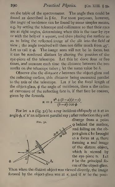
2QO Practical Physics. [CH. XIII. 59.
on the table of the spectrometer. The angle then could be
found as described in 62. For most purposes, however,the angle of incidence can be found by some simpler means,
e.g. by setting the telescope and collimator so that their axes
are at right angles, determining when this is the case by eyeor with the help of a square, and then placing the surface so
as to bring the reflected image of the slit into the field of
view; the angle required will then not differ much from 45.
Let us call it<f>.
The image seen will not be in focus, but
it can be rendered distinct by altering the position of the
eye-piece of the telescope. Let this be done four or five
times, and measure each time the distance between the two
marks on the telescope tubes;
let the mean value be b.
Observe also the distance c between the object-glass and
the reflecting surface, this distance being measured parallel
to the axis of the telescope. Let F be the focal length of
the object-glass, <j>the angle of incidence, then R the radius
of curvature of the reflecting face is, if that face be convex,
given by the formula
R = 2
FIG. 32.
(*-)For let A B
(fig. 32) be a ray incident obliquely at B at an
angle </>,A' B' an adjacent parallel ray ;
after reflection they will
diverge from a point
Q behind the surface,
and falling on the ob-
FJ^S^ ject-glass c be broughtto a focus at ^, there
forming a real imageof the distant object,
which is viewed bythe eye-piece D. Let
F be the principal fo-
cus of the object-glass.Then when the distant object was viewed directly, the imageformed by the object-glass was at F, and if D' be the posi-
CH. XIII. 59.] Mirrors and Lenses. 291
tion of the eye-piece adjusted to view it, we have D'F = D ^,
and hence F q = D D', but D D' is the distance the eye-piecehas been moved
\hence we have
F q b a, and c F = F;
.*. cq =
Also c B =<r,and since Q is the primary focal line l of a pencil
of parallel rays incident at an angle <
B Q = TJR COS
<f> ;
/. CQ = <r-f|
But
(fQ ~cq
~
i i
b-a
and
In the case of a concave surface of sufficiently large radius
it will be found that b is less than a; the eye-piece will re-
quire pushing in instead of pulling out;and the radius of
curvature is given by the formula
R =(a b] cos
We have supposed hitherto that the slit is at right angles
to the plane of reflexion, and the primary focus, therefore,
the one observed. If the slit be in the plane of reflexion
1 See Parkinson's Optics (edit. 1870), p. 60.
U 2
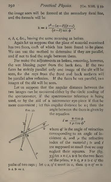
292 Practical Physics. [CH. XIII. 59.
the image seen will be formed at the secondary focal line,
and the formula will be
#, ^, r, &c., having the same meaning as before.
Again let us suppose that the plate of material examined
has two faces, each of which has been found to be plane.
We can use the method to determine if they are parallel,
and if not to find the angle between them.
For make the adjustments as before, removing, however,the wet blotting paper from the back face. If the two
faces be strictly parallel only one image of the slit will be
seen, for the rays from the front and back surfaces will
be parallel after reflexion. If the faces be not parallel, two
images of the slit will be seen.
Let us suppose that the angular distance between the
two images can be measured either by the circle reading of
the spectrometer, if the spectrometer telescope is being
used, or by the aid of a micrometer eye-piece if that be
more convenient;
let this angular distance be D;then the
FIG. 33 . angle between the faces is given bythe equation
. __ D cos</>
2fJLCOS <''
where <fi is the angle of refraction
corresponding to an angle of in-
cidence</>,
and yu the refractive
index of the material;D and /
are supposed so small that we mayneglect their squares. For
(fig.
33) let A B C,A D E be the two faces
of the prism, p B Q, p B D c Q' the
paths of two rays ;let Q B, Q' c meet in o, then Q o Q' = D
B A D = I.
CH. xiii. 59.] Mirrors and Lenses. 293
HenceD = QOQ' = OBA OCA
= \Tt (ft OCA,.'. OCA = ^7T <j>
D.
AgainDC A = EDC /= AD B -/
= D B C 2 / =Jj
TT <' 2 /.
Also since D c and c Q' are the directions of the same
ray inside and outside respectively,
COS O C A =fJ.COS D C A j
/. sin + D cos < = ^ (sin <' + 2 / cos <'),
neglecting D2 and ABut
sin < =yit
sin <';
./ _ r) cos
(p
2jjtcos
^>
/f
Again, it may happen that one or both faces of the
piece of glass are curved;
it will then act as a lens, and the
following method will give its focal length. The method
may be advantageously used for finding the focal length of
any long-focussed lens.
Direct the telescope to view the collimator slit, and focus
it; interpose the lens in front of the object-glass. Thefocus of the telescope will require altering to bring the slit
distinctly into view again.
Let us suppose that it requires to be pushed in a distance
x. Let c be the distance between the lens and the object-
glass of the telescope, then the parallel rays from the colli-
mator would be brought to a focus at a distance/ behind the
lens, i.e. at a distance fc behind the object-glass ; they
fall, however, on the object-glass, and are brought by it to a
focus at a point distant vx from the glass.
294 Practical Physics. [CH. XIII.
and from this we find
If the lens be concave, the eye-piece of the telescope will
require pulling out a distance x suppose ;and in this case
the rays falling on the object-glass will be diverging from a
point at a distance f-\-c in front of it, and will converge
to a point at a distance F+* behind it.
X
We infer, then, that if the eye-piece requires pushingin the lens is convex, and if it requires pulling out it is
concave.
Moreover, we note that all the above formulae both fur
reflexion and refraction are simplified if F = f;that is to
say, if the distance between the object-glass and the reflect-
ing surface or lens, as the case may be, is equal to the focal
length of the object-glass.
If this adjustment be made, and if x be the displace-
ment of the eye-piece in either case, we have for the radius
of curvature of the surface
__X COS
<j>
and for the focal length
/=>-.x
Experiments.
(1) Measure the curvature of the faces of the given pieceof glass.
(2) If both faces are plane, measure the angle between
them.
(3) If either face is curved, measure the focal length of the
lens formed by the glass.
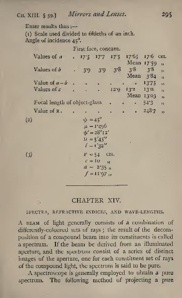
CH. XIII. 59.] Mirrors and Lenses. 295
Enter results thus :
(1) Scale used divided to fiftieths of an inch,
Angle of incidence 45.
First face, concave.
Values of a . 17*5 177 I7'5 17*65 I7'6 cm.
Mean 17-59
Values of b , 3-9 3'9 3'8 3* 3'8
Mean 3-84
Value of a-b ...... 1375 ,,
Values of c . . . 12-9 13-2 13-0.
Mean 13-03
Focal length of object-glass . . . 54*3
Value of R....... 2487
(2) =45I* =1-496
(3) 1'' = 54 cm.
c = 10
n = 2-35
CHAPTER XIV.
SPECTRA, REFRACTIVE INDICES, AND WAVE-LENGTHS.
A BEAM of light generally consists of a combination of
differently-coloured sets of rays ;the result of the decom-
position of a compound beam into its constituents is called
a spectrum. If the beam be derived from an illuminated
aperture, and the spectrum consist of a series of distinct
images of the aperture, one for each constituent set of rays
of the compound light, the spectrum is said to be pure.
A spectroscope is generally employed to obtain a pure
spectrum. The following method of projecting a pure
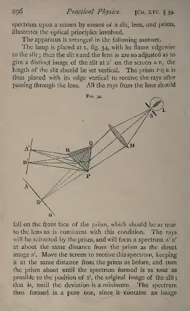
296 Practical Physics. [Cn. XIV. 59.
spectrum upon a screen by means of a slit, lens, and prism,
illustrates the optical principles involved.
The apparatus is arranged in the following manner.
The lamp is placed at L, fig. 34, with its flame edgewiseto the slit
;then the slit s and the lens M are so adjusted as to
give a distinct image of the slit at s' on the screen A B; the
length of the slit should be set vertical. The prism P Q R is
then placed with its edge vertical to receive the rays after
passing through the lens. All the rays from the lens should
FIG. 34.
fall on the front face of the prism, which should be as near
to the lens as is consistent with this condition. The rayswill be refracted by the prism, and will form a spectrum A' B'
at about the same distance from the prism as the direct
image s'. Move the screen to receive this spectrum, keepingit at the same distance from the prism as before, and turn
the prism about until the spectrum formed is as near as
possible to the position of s', the original image of the slit ;
that is, until the deviation is a minimum. The spectrumthus formed is a pure one, since it contains an image
CH. XIV. 60.] Spectra, Refractive Indices, &c. 297
of the slit for every different kind of light contained in the
incident beam.
60. The Spectroscope.
Mapping a Spectrum.
We shall suppose the spectroscope has more than one
prism.
Turn the telescope to view some distant object throughan open window, and focus it. In doing this adjust first
the eye-piece until the cross-wires are seen distinctly, then
move the eye-piece and cross-wires by means of the screw
until the distant object is clear. The instrument should be
focussed so that on moving the eye about in front of the
eye-lens no displacement of the image relatively to the
cross-wires can be seen.
Remove the prisms, and if possible turn the telescopeto look directly into the collimator. Illuminate the slit
and focus the collimator until the slit is seen distinctly.
Replace one prism and turn the telescope so as to receive
the refracted beam. Turn the prism round an axis parallel
to its edge until the deviation of some fixed line is a mini-
mum (see 62, p. 311).
For this adjustment we can use a Bunsen burner with a
sodium flame.
If the prism have levelling screws, adjust these until the
prism is level.
To test when this is the case fix a hair across the slit,
adjusting it so that when viewed directly it may coincide
with the horizontal cross-wire of the eye-piece. The hair
will be seen in the refracted image cutting the spectrum
horizontally. Adjust the levelling screws of the prism until
this line of section coincides with the cross-wire.
In some instruments the prisms have no adjusting
screws, but their bases are ground by the maker so as to
be at right angles to the edge.
Having placed the first prism in position, secure it there
298 Practical Physics. [CH. XIV. 60.
with a clamp, and proceed to adjust the second and other
prisms in the same way.The table of the spectroscope is graduated into degrees
and minutes, or in some instruments there is a third tube
carrying at one end a scale and at the other a lens whosefocal length is the length of the tube. The scale is illu-
minated from behind by a lamp and is placed so that the
rays which issue from the lens fall on the face of the prismnearest the observing telescope, and being there reflected
form an image of the scale in the focus of the telescope.
Bring the vertical cross-wire, using the clamp and tan-
gent-screw, over the image of the slit illuminated by the
yellow sodium flame and read the scale and vernier, or note
the reading of the reflected scale with which it coincides.
Replace the sodium flame by some other source of light
the spectrum of which is a line or series of lines, as, for
example, a flame coloured by a salt of strontium, lithium, or
barium, and take in each case the readings of the reflected
scale or of the vernier when the cross-wire coincides with
the bright lines.
Now the wave-lengths of these lines are known;we can
therefore lay down on a piece of logarithm paper a series of
points, the ordinates of which shall represent wave-lengths,
while the abscissae represent the graduations of the circle or
scale.
If we make a sufficient number of observations, say
from ten to fifteen, we can draw a curve through them, and
by the aid of this curve can determine the wave-length of
any unknown line ; for we have merely to observe the reading
of the circle or scale when the cross-wire is over this line and
draw the ordinate of the curve corresponding to the reading
observed. This ordinate gives the wave-length required.1
A diagram shewing the positions of the lines of a spec-
trum as referred to the circle readings or the graduations of
the reflected scale is called a map of the spectrum.
In using the map at any future time we must adjust the
1 See Glazebrook Physual Optics, p. 113.

CH. XIV. 60.] Spectra, Refractive Indices, &c. 299
scale or circle so that its zero occupies the same position
with reference to the spectrum. This can be done by
arranging that some well-known line e.g. D should always
coincide with the same scale division or circle reading.
Instead of using the light from a Bunsen burner with
metallic salts in the flame, we may employ the electric spark
from an induction coil either in a vacuum tube or between
metallic points in air.
If the vacuum tube be used, two thin wires from the
secondary of the coil are connected to the poles of the tube
pieces of platinum wire sealed into the glass. The primary
wire of the coil is connected with a battery of two or three
Grove cells, and on making contact with the commutator
the spark passes through the tube. This is placed with its
narrow portion close up to and parallel to the slit, and the
spectroscope observations made as before. If the spark
be taken between two metallic poles in air, the two poles
placed in the spark-holder are connected with the second-
ary and placed at a distance of two or three millimetres
apart, and the spark passed between them.
The spark-holder is placed in front of the slit, and either
the spark is viewed directly or a real image of it is formed
on the slit by means of a convex lens of short focus.
With this arrangement, in addition to the spectrum of
the metal formed by the light from the glowing particles of
metal, which are carried across between the poles by the
spark, we get the spectrum of the air which is rendered in-
candescent by the passage of the spark. The lines will
probably be all somewhat faint, owing to the small quantityof electricity which passes at each discharge.
To remedy this, connect the poles of the secondary coil
with the outside and inside coatings of a Leyden jar, as is
shewn in fig. 35. Some of the electricity of the secondarycoil is used to charge the jar; the difference of potential
between the metallic poles rises less rapidly, so that dis-
charges take place less frequently than without the jar;
but when the spark does pass, the whole charge of the jar
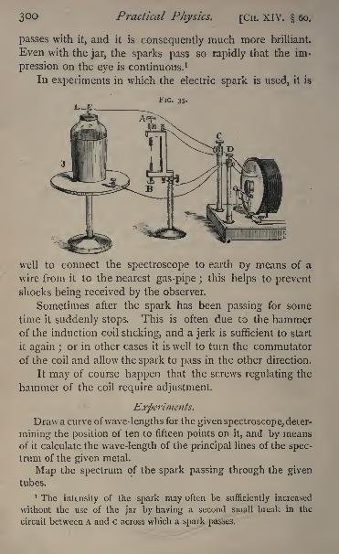
3OO Practical Physics. [CH. XIV. 60,
passes with it, and it is consequently much more brilliant.
Even with the jar, the sparks pass so rapidly that the im-
pression on the eye is continuous. 1
In experiments in which the electric spark is used, it is
FIG. 35.
well to connect the spectroscope to earth Dy means of a
wire from it to the nearest gas-pipe ;this helps to prevent
shocks being received by the observer.
Sometimes after the spark has been passing for some
time it suddenly stops. This is often due to the hammerof the induction coil sticking, and a jerk is sufficient to start
it again ;or in other cases it is well to turn the commutator
of the coil and allow the spark to pass in the other direction.
It may of course happen that the screws regulating the
hammer of the coil require adjustment.
Experiments.
Draw a curve ofwave-lengths for the given spectroscope, deter-
mining the position of ten to fifteen points on it, and by meansof it calculate the wave-length of the principal lines of the spec-trum of the given metal.
Map the spectrum of the spark passing through the giventubes.
1 The intensity of the spark may often be sufficiently increased
without the use of the jar by having a second small break in the
circuit between A and C across which a spark passes.
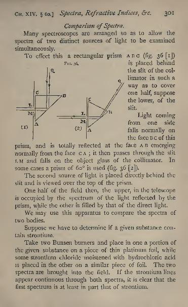
CH. XIV. 60.] Spectra, Refractive Indices, &c. 301
Comparison of Spectra.
Many spectroscopes are arranged so as to allow the
spectra of two distinct sources of light to be examined
simultaneously.
To effect this a rectangular prism ABC (fig. 36 [ij)
FIG. 36. is placed behind
;<l the slit of the col-
limator in such a
way as to cover
one half, supposethe lower, of the
slit.
Light comingfrom one side
falls normally on
the face B c of this
prism, and is totally reflected at the face AB emerging
normally from the face c A;
it then passes through the slit
LM and falls on the object glass of the collimator. In
some cases a prism of 60 is used (fig. 36 [2]).
The second source of light is placed directly behind the
slit and is viewed over the top of the prism.
One half of the field then, the upper, in the telescope
is occupied by the spectrum of the light reflected by the
prism, while the other is filled by that of the direct light.
We may use this apparatus to compare the spectra of
two bodies.
Suppose we have to determine if a given substance con-
tain strontium.
Take two Bunsen burners and place in one a portion of
the given substance on a piece of thin platinum foil, while
some strontium chloride moistened with hydrochloric acid
is placed in the other on a similar piece of foil. The two
spectra are brought into the field. If the strontium lines
appear continuous through both spectra, it is clear that the
first spectrum is at least in part that of strontium.
302 Ptactical Physics. [CH. XIV. 60.
As we have seen already, if we pass a spark in air
between metallic poles we get the air lines as well as those
due to the metal. We may use this comparison method
to distinguish between the air lines and those of the metal.
For let one set of poles be made of the metal in question,
and take for the other set some metal with a simple known
spectrum, platinum for example. Arrange the apparatus as
described to observe the two spectra. The lines commonto both are either air lines or are due to some common im-
purity of the two metals;the other lines in the one spectrum
are those of platinum, in the second they arise from the
metal in question.
After practice it is quite easy to recognise the distinctive
lines of many substances without actual comparison of their
spectra with that of a standard.
Experiment. Compare the spectra of the sparks passingbetween platinum poles and poles of the given metal.
Note the wave-lengths of the principal lines in the spark
spectrum of the given metal.
On Refractive Indices.
If a ray of homogeneous light fall on a refracting mediumat an angle of incidence
<jf>,the angle of refraction being <';
then the ratio sin </sin <' is constant for all values of <, and
is the refractive index for light of the given refrangibility
going from the first to the second medium.
Let us suppose the first medium is air, then it is not
difficult to determine by optical experiments the value of
the angle <, but <' cannot be determined with any real
approach to accuracy. The determination of ft, the refrac-
tive index, is therefore generally effected by indirect means.
We proceed to describe some of these.l
1 For proofs of the optical formulce which occur in the succeeding
sections, we may refer the reader to Glazebrook's Physical Optics^
chaps, iv. and viii.
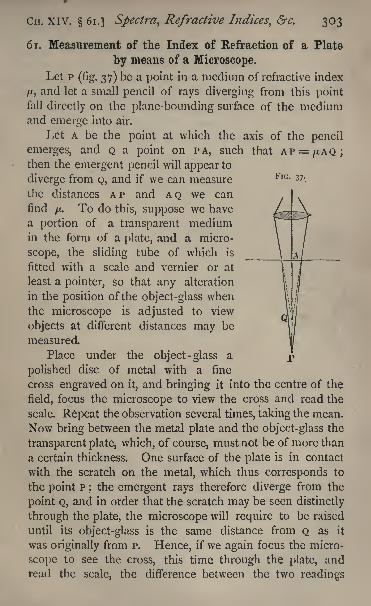
FIG. 37.
CH. XIV. 61.] Spectra, Refractive Indices, &c. 303
6 1. Measurement of the Index of Refraction of a Plate
by means of a Microscope.
Let P (fig. 37) be a point in a medium of refractive index
/A, and let a small pencil of rays diverging from this pointfall directly on the plane-bounding surface of the mediumand emerge into air.
Let A be the point at which the axis of the pencil
emerges, and Q a point on PA, such that AP = /XAQ;then the emergent pencil will appear to
diverge from Q, and if we can measure
the distances AP and AQ we can
find/x.
To do this, suppose we have
a portion of a transparent mediumin the form of a plate, and a micro-
scope, the sliding tube of which is
fitted with a scale and vernier or at
least a pointer, so that any alteration
in the position of the object-glass whenthe microscope is adjusted to view
objects at different distances may be
measured.
Place under the object-glass a
polished disc, of metal with a fine
cross engraved on it, and bringing it into the centre of the
field, focus the microscope to view the cross and read the
scale. Repeat the observation several times, taking the mean.
Now bring between the metal plate and the object-glass the
transparent plate, which, of course, must not be of more than
a certain thickness. One surface of the plate is in contact
with the scratch on the metal, which thus corresponds to
the point P;the emergent rays therefore diverge from the
point Q, and in order that the scratch may be seen distinctly
through the plate, the microscope will require to be raised
until its object-glass is the same distance from Q as it
was originally from p. Hence, if we again focus the micro-
scope to see the cross, this time through the plate, andread the scale, the difference between the two readings
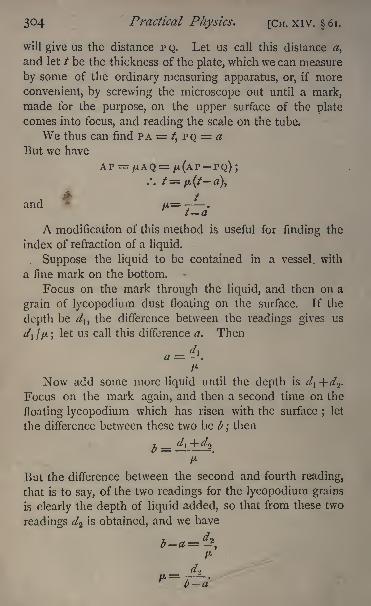
304 Practical Physics. [CH. XIV. 61.
will give us the distance p Q. Let us call this distance a,
and let / be the thickness of the plate, which we can measure
by some of the ordinary measuring apparatus, or, if more
convenient, by screwing the microscope out until a mark,made for the purpose, on the upper surface of the plate
comes into focus, and reading the scale on the tube.
We thus can find PA = /, PQ = a
But we have
/. /=,*(/-*),
1* '
and u=- .
t a
A modification of this method is useful for finding the
index of refraction of a liquid.
Suppose the liquid to be contained in a vessel, with
a fine mark on the bottom.
Focus on the mark through the liquid, and then on a
grain of lycopodium dust floating on the surface. If the
depth be d\, the difference between the readings gives us
^, //>.;let us call this difference a. Then
Now add some more liquid until the depth is d\ +d<>.
Focus on the mark again, and then a second time on the
floating lycopodium which has risen with the surface;
let
the difference between these two be b ;then
But the difference between the second and fourth reading,
that is to say, of the two readings for the lycopodium grains
is clearly the depth of liquid added, so that from these two
readings d^ is obtained, and we have
CH. XIV. 62.] Spectra, Refractive Indices, &c. 307
In experiments in which a prism is used it is generally
necessary that the edge of the prism should be parallel to
the axis of rotation of the telescope. Turn the telescope
to view the slit directly. Fix by means of soft wax a hair
or silk fibre across the slit, so that it may appear to coincide
with the horizontal cross-wire or point of the needle when
seen through the instrument; or, as is often more con-
venient, cover up part of the slit, making the junction of
the covered and uncovered portions coincide with the
horizontal wire. Fix the prism with wax or cement on to
the levelling table in the centre of the instrument, so that
the light from the collimator is reflected from two of its
faces, and adjust it by hand, so that the two reflected imagesof the slit can be brought in turn into the field of view
of the telescope. Alter the set screws of the levelling table
until the image of the hair across the slit when reflected
from either of the two faces, and seen through the tele-
scope, coincides with the intersection of the cross-wires.
When this is the case the prism is in the required position.
The edge of the prism may also be adjusted to be
parallel to the axis of rotation by setting the two faces suc-
cessively at right angles to the line of collimation of the
telescope. This may be done with great accuracy by the
following optical method. Illuminate the cross-wires of the
telescope, and adjust the face of the prism so that a reflected
image of the cross-wires is seen in the field of view of the
telescope coincident with the wires themselves. This can
only be the case when the pencil of light from the inter-
section of the wires is rendered parallel by refraction at the
object-glass of the telescope, and reflected normally by the
face of the prism, so that each ray returns along its own
path. An aperture is provided in the eye-piece tubes of
some instruments for the purpose of illuminating the wires ;
in the absence of any such provision, a piece of plane glass,
placed at a suitable angle in front of the eye- piece, may be
used. It is sometimes difficult to catch sight of the reflected
X 2

308 Practical Physics. [CH. XIV. 62.
image in the first instance, and it is generally advisable,
in consequence, to make a rough adjustment with the eye-
piece removed, using a lens of low magnifying powarinstead.
When fixing the prism on to the table, it is best to take
care that one face of the prism is perpendicular to the line
joining two of the set screws of the levelling table. Level
this face first. The second face can then be adjusted
by simply altering the third screw, which will .not disturb
the first face. It is well to place the prism so that the light
used passes as nearly as possible through the central portion
of the object-glasses of the collimator and telescope.
Measurements zvith the Spectrometer.
(1) To verify the Law ofReflexion*This requires the table on which the prism is fixed to be
capable of motion round the same axis as the telescope, and
to have a vernier attached.
Adjust the apparatus so that the reflected image of the
slit coincides with the cross-wire, and read the position of
the telescope and prism. The slit should be made as narrow
as possible.
If the instrument has two verniers for the telescope
opposite to each other, read both and take the mean of the
readings. Errors of centering are thus eliminated.
Move the prism to another position, adjust the telescope
as before, and take readings of the position of the prismand telescope. Subtract these results from the former re-
spectively. It will be found that the angle moved through
by the telescope is always twice that moved through by the
prism.
(2) To Measure the Angle oj a Prism.
(a) Keeping the prism fixed. Adjust the prism so that
an image of the slit can be seen distinctly by reflexion from

Cn. XIV. 62.] Spectra, Refractive Indices, &c. 309
each of two of its faces, and its edge is parallel to the axis
of rotation of the telescope.
Adjust the telescope so that the image of the slit re-
flected from one face coincides with the vertical cross-wire,
and read the verniers. Move the telescope until the same
coincidence is observed for the image reflected from the
second face, and read again.
The difference of the two readings is twice the angle
required, provided the incident light is parallel.
(b) Keeping the telescope fixed. Move the prism until
the image of the slit reflected from one face coincides
with the vertical cross-wire, and read the verniers for the
prism.
Turn the prism until the same coincidence is observed
for the other face, and read again.
Then the defect of the difference of the two readingsfrom 1 80 is the angle required.
Verify by repeating the measurements,
Experiments.
(1) Verify the law of reflexion.
(2) Measure by methods(ti)
and(/>)
the angle of the given
prism.
Enter results thus:
(1) Displacement of telescope . 5 43' 24 o' -15"
prism . 2 51' 12 o' o''
(2) Angle of prism
By method (a) 60 7' 30" 60 7' 50" mean 60 7' 40"
By method(l>)
60 8' 15" 60 7' 45" mean 60 8' o"
(3) To Measure the Refractive Index ofa Prism.
First Method. The spectrometer requires adjusting and
the prism levelling on its stand, as before. The angle of the
prism must be measured, as described. To obtain an accurate
result, it is necessary that the light which falls on the face ofthe
3io Practical Physics. [CH. xiv. 62.
prism should be a parallel pencil. One method of obtainingthis has already been given. The following, due to Professor
Schuster, may often be more convenient, and is, moreover,more accurate. Let us suppose that the slit is illuminated
with homogeneous light, a sodium flame, for example, and
the prism so placed that the light passes through it, being
deflected, of course, towards the thick part. Place the tele-
scope so as to view the refracted image. Then it will be
found that, on turning the prism round continuously in one
direction, the image seen appears to move towards the
direction of the incident light, and after turning throughsome distance the image begins to move back in the oppo-site direction and again comes into the centre of the field.
There are thus, in general, for a given position of the tele-
scope, two positions of the prism, for which the image can
be brought into the centre of the field of the telescope. In
one of these the angle of incidence is greater than that for
minimum deviation, in the other less. Turn the prism into
the first of these positions ;in general the image will appear
blurred and indistinct. Focus the telescope until it is clear.
Then turn the prism into the second position. The imagenow seen will not be clear and in focus unless the colli-
mator happens to be in adjustment. Focus the collimator.
Turn the prism back again into the first position and focus
the telescope, then again to the second and focus the colli-
mator.
After this has been done two or three times, the slit will
be in focus without alteration in both positions of the prism,and when this is the case the rays which fall on the telescopeare parallel ;
for since the slit remains in focus, its virtual
image formed by the prism is at the same distance from the
telescope in the two positions of the prism; that is to say, the
distance between the prism and the virtual image of the slit is
not altered by altering the angle of incidence, but this can onlybe the case when that distance is infinite that is, when the
rays are parallel on leaving the prism ;and since the faces
CH. XIV. 62. J Spectra, Refractive Indices>&c. 311
of the prism are plane, the rays emerging from the collimator
are parallel also. Thus both telescope and collimator maybe brought into adjustment.
The simplest method of measuring the refractive index
is to observe the angle of the prism and the minimum de-
viation. We have seen how to measure the former. For
the latter, turn the telescope to view the light coming directly
from the collimator. When the prism is in position, it of
course intercepts the light, but it can generally be turned
round so as to allow sufficient light for the purpose to pass
on one side of it. Clamp the telescope and adjust with the
tangent screw until the intersection of the cross-wires or the
end of the needle comes exactly into the centre of the slit ;
then read the scale and vernier. Repeat the observation
several times and take the mean of the readings. If it be
impossible to turn the prism without removing it from its
place, so as to view the direct image, a method to be de-
scribed later on may be used.
Turn the prism to receive on one face the light emergingfrom the collimator, and move the telescope to view the
refracted image.Place the prism so that the deviation of the refracted
light is a minimum. To determine this position accurately,
turn the prism round the axis of the circle so that the
refracted image appears to move towards the direction of
the incident light, and continue the motion until the image
appears to stop. This position can easily be found roughly.
Bring the cross-wire of the telescope to cover the image of
the slit, and again turn the prism slightly first one way and
then the other. If for motion in both directions the image
appears to move away from the direction of the incident
light, the prism is in the required position. In general,
however, for the one direction of rotation the motion of the
image will be towards the direct light, and the prism must
be turned until the image ceases to move in that direction.
The first setting gave us an approximate position for the
3 1.2 Practical Physics. [CH. XIV. 62.
prism. By bringing the cross-wires over the image, and
then moving the prism, we are able to detect with greatease any small motion which we should not have noticed
had there been no mark to which to refer it. Having set
the prism, place the telescope, using the clamp and tangentscrew so that the cross- wire bisects the image of the slit, and
read the vernier.
Displace the prism and telescope, set it again, and take
a second reading. Repeat several times. The mean of the
readings obtained will be the minimum deviation reading,
and the difference between it and the mean of the direct
readings the minimum deviation. With a good instrument
and reasonable care the readings should not differ amongthemselves by more than i'.
Having obtained the minimum deviation D, and the
angle of the prism *',the refractive index
/x,is given by
=sn
To check the result, the prisrn should be turned so that
the other face becomes the face of incidence, and the devia-
tion measured in the opposite direction.
If we cannot observe the direct light, we may note the
deviation reading on each side of it that is, when first one
face and then the other is made the face of incidence the
difference between the two readings is twice the minimumdeviation required, while half their sum gives the direct
reading.
To determine the refractive index of a liquid we must
enclose it in a hollow prism, the faces of which are pieces
of accurately worked plane parallel glass, and measure its
refractive index in the same way as for a solid.
Experiment. Determine the refractive index of the given
prism,
CH. XIV. 62.] Spectra, Refractive Indices, &c. 313
Enter results thus:
Direct reading Deviation reading (i) Deviation reading (2)
183 15' 40" 143 29' 223 2'
183 15' 50" 143 28' 50 223 i' 30"l8 3 15' 3" ! 43 2 9' I0
"223 i' 30"
Mean 183 15' 40" 143 29' 223 T 40"Deviation (i) 39 46' 40"Deviation (2) .... 39 46' o"
Mean 39 46' 20"
Ani,r1 e of the prism . . . 60 o' o"
Hence /z= 1*5295.
Second Method. The following is another method of
measuring the refractive index, which is useful if the angle
of the prism be sufficiently small. Let the light from the
collimator fall perpendicularly on the face of incidence.
Then if / be the angle of the prism and D the deviation,
since, using the ordinary notation,
/. I//= /
j/r= D 4- /,
and ft= sin i^/sin \f/
r = sin (o + /)/sin /".
We require to place the prism so that the face of incidence
is at right angles to the incident light.
Turn the telescope to view the direct light and read the
vernier.
Place the prism in position and level it, as alreadydescribed. Turn the telescope so that the vernier readingdiffers by 90 from the direct reading. Thus, if the direct
reading be 183 15' 30", turn the telescope till the vernier
reads 273 15' 30". This can easily be done by the helpof the clamp and tangent screw. Clamp the telescope in
this position ; the axes of the collimator and telescope are
now at right angles.
Turn the prism until the image of the slit reflected from
one face comes into the field, and adjust it until there is
3*4 Practical Physics. [Cn. XIV. 62.
coincidence between this image and the cross- wire. The
light falling on the prism is turned through a right angle bythe reflexion. The angle of incidence is therefore 45
exactly. Read the vernier attached to the table on which
the prism rests, and then turn the prism through 45 exactly,
so as to decrease the angle of incidence;then the face of
incidence will evidently be at right angles to the incident
light. Now turn the telescope to view the refracted image,and read the vernier; the difference between the readingand the direct reading is the deviation. The angle of the
prism can be measured by either of the methods alreadydescribed
;it must be less than sin
~ 1
(i/ju), which for glass
is about 42 ,otherwise the light will not emerge from the
second face, but be totally reflected there. The refractive
index can now be calculated from the formula.
A similar observation will give us the angle of incidence
at which the light falls on any reflecting surface;thus turn
the telescope to view the direct light, and let the vernier
reading be a, then turn it to view the reflected image, and
let the reading be /?. Then a fi measures the deflection
of the light, and if < be the angle of incidence, we can shew
that the deviation is 180 2.
Experiment. Determine the refractive index of the given
prism for sodium light.
Enter the results thus:
Angle of prism .... 15 35' 10''
Direct reading Deviation reading
183 15' 10" 191 53' 30"
183 is' $o" 191 54' 20"
183 15' 30" 191 53' 40"Mean 183 15' 30" 191 53' 50"
Deviation . . . 8 38' 20"
Value of /z. . . . 1-5271.
CH. XIV. 62.] Spectra, Refractive Indices, &c. 315
(4) To Measure the Wave-Length of Light by means of a
Diffraction Grating.
A diffraction grating consists of a number of fine lines
ruled at equal distances apart on a plate of glass a trans-
mission grating ;or of speculum metal a reflexion grating.
We will consider the former. If a parallel pencil of homo-
geneous light fall normally on such a grating, the origin
of light being a slit parallel to the lines of the grating, a
series of diffracted images of the slit will be seen, and if On
be the deviation of the light which forms the ;/th image,
reckoning from the direction of the incident light, d the
distance between the centres of two consecutive lines of the
grating, and A the wave-length, we have
A = -^sin 6Ln
The quantity d is generally taken as known, beingdetermined at the time of ruling the grating. The spectro-
meter is used to determine &.
The telescope and collimator are adjusted for parallel
rays, and the grating placed on the table of the instrument
with its lines approximately parallel to the slit. For con-
venience of adjustment it is best to place it so that its
plane is at right angles to the line joining two of the levelling
screws. ^The grating must now "be levelled, i.e. adjusted so
that its plane is at right angles to the table of the spectro-
meter. This is done by the method described above for the
prism. Then place it with its plane approximately at right
angles to the incident light, and examine the diffracted
images of the slit. The plane of the grating is at right
angles to the line joining two of the levelling screws ;the
third screw then can be adjusted without altering the anglebetween the plane of the grating and the table of the
spectrometer. Adjust the third screw until the slit appearsas distinct as possible ;
the lines of the grating will then be
parallel to the slit.
316 Practical Physics. [Cir. XIV. 62.
Turn the table carrying the grating so as to allow the
direct light to pass it; adjust the telescope so that the vertical
cross-wire bisects the image of the slit seen directly, and
read the vernier. This gives us the direct reading. Place
the grating with its plane accurately perpendicular to the
incident rays, as described above, and turn the telescope
to view the diffracted images in turn, taking the correspond-
ing readings of the vernier. The difference between these
and the direct reading gives us the deviations 150.2 ,
&c-
A series of diffracted images will be formed on each side
of the direct rays. Turn the telescope to view the second
series, and we get another set of values of the deviation
0',, 0'.2 ,&c. If we had made all our adjustments and
observations with absolute accuracy, the corresponding
values 0,, 0' b c., would have been the same;
as it is their
mean will be more accurate than either.
Take the mean and substitute in the formula
We thus obtain a set of values of A.
If the light be not homogeneous, we get, instead of the
separate images of the slit, more or less continuous spec-
tra, crossed it may be, as in the case of the solar spectrum,
by dark lines, or consisting, if the incandescent body be gas
at a low pressure, of a series of bright lines.
In some cases it is most convenient to place the grating
so that the light falls on it at a known angle, $ say. Let
\l/be the angle which the diffracted beam makes with the
normal to the grating, and the deviation for the wth
image, < and\j/ being measured on the same side of the
normal, then it may be shewn that
0= < + $and
n\ d?(sin < + sin\f/)
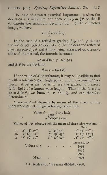
Cn. XIV. 62]. Spectra, Refractive Indices, &c. 317
The case of greatest practical importance is when the
deviation is a minimum, and then < = $ = J 0, so that if
On denote the minimum deviation for the ;/th diffracted
image, we have
X ss -4 sin 4,
In the case of a reflexion grating, if < and $ denote
the angles between the normal and the incident and reflected
rays respectively, < andfynow being measured on opposite
sides of the normal, the formula becomes
n\ =. d (sin tysin <) ;
and if be the deviation
If the value of d be unknown, it may be possible to find
it with a microscope of high power and a micrometer eye-
piece. A better method is to use the grating to measure
M for light of a known wave-length. Then in the formula,
n\ = dsinOm we know X, ;/, and M and can therefore
determine d.
Experiment* Determine by means of the given gratingthe wave-length of the given homogeneous light.
Value d- Paris inch3000
= -0009023 cm.
Values of deviations, each the mean of three observations
Meani 3 44' 30" 3 44' 45" 3 44' 37
"-5
2. 7 29' o" 7'J
29' 45" 7 29' 2 2"-5
3 n 16' 45" 11 17' 30" 11 if 7"-s
Tenth metres '
Values of X . . . . 5895
5S93
5915Mean . . . 5901
1 A * tenth metre 'is I metre divided by io 10
,
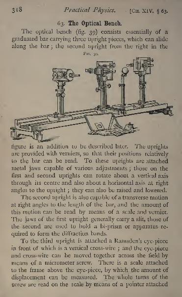
3 1 8 Practical Physics, [CH. XIV. 63.
63. The Optical Bench.
The optical bench (fig. 39) consists essentially of a
graduated bar carrying three upright pieces, which can slide
along the bar;the second upright from the right in the
FIG. 39.
figure is an addition to be described later. The uprightsare provided with verniers, so that their positions relatively
to the bar can be read. To these uprights are attached
metal jaws capable of various adjustments ; those on the
first and second uprights can rotate about a vertical axis
through its centre and also about a horizontal axis at right
angles to the upiight ; they can also be raised and lowered.
The second upright is also capable of a transverse motion
at right angles to the length of the bar, and the amount of
this motion can be read by means of a scale and vernier.
The jaws of the first upright generally carry a slit, those of
the second are used to hold a bi-prism or apparatus re-
quired to form the diffraction bands.
To the third upright is attached a Ramsden's eye-piece
in front of which is a vertical cross-wire; and the eye-piece
and cross-wire can be moved together across the field bymeans of a micrometer screw. There is a scale attached
to the frame above the eye-piece, by which the amount of
displacement can be measured. The whole turns of the
screw are read on the scale by means of a pointer attached
CH. XIV. 63.] Spectra, Refractive Indices, &c. 319
to the eye-piece. The fractions of a turn are given by the
graduations of the micrometer head.
The divisions of the scale are half-millimetres and the
micrometer head is divided into 100 parts.
(i) To Measure the Wave-Length of Liglit by means ofFresnePs Biprism.
The following adjustments are required :
(1) The centre of the slit, the centre of the bi-prism, andthe centre of the eye-piece should be in one straight line.
(2) This line should be parallel to the graduated scale
of the bench.
(3) The plane face of the bi prism should be at right
angles to this line.
(4) The plane of motion of the eye-piece should also be
at right angles to the same line.
(5) The cross- wire in the eye-piece, the edge of the
prism, and the slit should be parallel to each other, and
vertical, that is to say, at right angles to the direction of
motion of the eye-piece.
To describe the adjustments, we shall begin with (5).
Focus the eye -piece on the cross-wire, and by means of the
flat disc to which it is attached, turn the latter round the axis of
the eye-piece until it appears to be vertical; in practice the
eye is a sufficiently accurate judge of when this is the case.
Draw the third upright some way back, and insert
between it and the slit a convex lens. 1 Illuminate the slit
by means of a lamp, and move the lens until a real imageof the slit is formed in the plane of the cross-wire. Turn the
slit round by means of the tangent screw until this imageis parallel to the cross-wire. The slit must be held securelyand without shake in the jaws.
Move the eye-piece up to the slit and adjust the vertical
and micrometer screws until the axis of the eye -piece appearsto pass nearly through the centre of the slit, turning at the
same time the eye-piece round the vertical axis until its axis
appears parallel to the scale. This secures (4) approximately.1 This is shewn in the figure.
320 Practical Physics. [CH. XIV. 63.
Draw the eye-piece away from the slit, say 20 or 30 cm.
off, and place the bi-prism in position, turning it aboutuntil its plane face appears to be at right angles to the scale
of the bench. This secures (3) approximately.Look through the eye-piece. A blurred image of FresneFs
bands may probably be visible. By means of the traversingscrew move the second upright at right angles to the scale
until this image occupies the centre of the field. If the
bands be not visible, continue to move the screw until theycome into the field.
It may be necessary to alter the height of the bi-prism
by means of the vertical adjustment so that its centre maybe at about the same level as those of the slit and eye-piece.
By means of the tangent screw turn the bi-prism roundthe horizontal axis at right angles to its own plane until the
lines appear bright and sharp.
Adjustment (5) is then complete.Now draw the eye-piece back along the scale
;if the
lines still remain in the centre of the field of view, it follows
that the slit, the centre of the bi-prism, and the centre of the
eye-piece are in one straight line parallel to the scale.
If this be not the case, alter the position of the eye-piece
by means of the micrometer screw and that of the bi-prism
by means of the traversing screw with which the second
stand is furnished, until the lines are seen in the centre of
the field for all positions of the eye-piece along the scale bar
of the instrument.
Adjustments (i) and (2) have thus been effected.
For (3) and (4) it is generally sufficient to adjust "by eye,
as already described. If greater accuracy be required, the
following method will secure it.
Move the lamp to one side of the slit and arrange a
small mirror so as to reflect the light through the slit and
along the axis of the instrument. The mirror must only cover
one-half of the slit, which will have to be opened some-
what widely. Place your eye so as^to look through the other
half of the slit in the same direction as the light. Images
CH. XIV. 63.] Spectra, Refractive Indices, &c. 321
of the slit reflected from the faces of the bi-prism and
probably from other parts of the apparatus will be seen.
Suppose the flat face of the bi-prism is towards the slit.
Turn the prism round a vertical axis until the image reflected
at the flat face appears directly behind the centre-line of the
bi-prism, then clearly the plane of the bi-prism is at right
angles to the incident light, and that is parallel to the scale
In making the adjustment, the stand holding the prismshould be placed as far as may be from the slit.
If the bevelled face be towards the slit, two images will
be seen, and these must be adjusted symmetrically one oneach side of the centre.
To adjust the eye-piece employ the same method, usingthe image reflected from the front lens or from one of the
brass plates which are parallel to it. To do this it may be
necessary to remove the bi-prism if this be the case, the
eye-piece adjustment must be made first.
As soon as the adjustments are made the various movingpieces must be clamped securely.
It is necessary for many purposes to know the distance
between the slit and the cross-wire or focal plane of the eye-
piece. The graduations along the bar of the instrument will
not give us this directly; for we require, in addition, the
horizontal distance between the zero of the vernier and the
slit or cross-wire respectively.To allow for these, take a rod of known length, a
centimetres suppose ; place one end in contact with the slit,
and bring up the eye-piece stand until the other end is in
the focal plane. Read the distance as given by the scale
between the slit and eye-piece uprights ; let it be b centi-
metres.
Then clearly the correction a b centimetres must beadded to any scale reading to give the distance betweenthe slit and the eye-piece. This correction should be de-
termined before the bi-prism is finally placed in position.To use the bi-prism to measure A, the wave-length of
Y
322 Practical Physics. [CH. XIV. 05.
light, we require to know c, the distance between the virtual
images formed by the bi -prism, x the distance between con-
secutive bright bands, and a the distance between slit and
eye-piece.1
Then we haveX
The distance x is measured by means of the micrometer
attached to the eye-piece.
In order that x may be large, c should be small and a
large. This is attained by making the distance between the
slit and the prism small, 10 to 20 cm., and that between the
prism and the eye-piece considerable. Of course the bands are
fainter and less distinct if this distance be very large; it must
therefore not exceed a certain limit, which depends greatly on
the source of light used.
Suppose we have a Bunsen burner with a sodium bead
in it.
In making the measurement of x, the micrometer screw
of the eye- piece should be always turned in the same direc-
tion. This avoids the error of '
lost time' due to any shake
in the screw or looseness between the screw and the nut.
Turn the screw to carry the cross-wire as near to one
edge of the field as is convenient and set it on the centre of
a bright band. Read the scale and micrometer; let the
reading be 10*35. Turn the screw until the wire is over the
next bright band and read again ;let the reading be 1072.
Proceed thus across the field, reading the position of every
bright line, and taking an even number, say ten or twelve
readings.
Let them be
(1) 10-35 (6) 12-15
(2) 1072 (7) 12-53
(3) 11-07 (8) 12-88
(4) n'45 (9) 13*24
(5) "'8i (10) i3'591 Sec Glazebrook, Physical Optics, chap. v.
CH. XIV. 63.] Spectra, Refractive Indices, &c. 323
Subtract the first from the sixth, the second from the
seventh, and so on.
Then (6)-(i)= '80
( 7)-(2)= -81
(8) -(3)= * i
(9) -(4)= 79(io)-(5)= 78
Mean . , . 1798
Each of these differences is the space covered by a
group of six bright lines. Take the mean. We have 1798.
Dividing by five we get the mean value for x. Thus
x -359 mm.
To determine a we have only to read the verniers at
the slit and eye-piece respectively, take the difference and
correct it as already described for index error.
To determine c9draw the eye-piece away to about
50 centimetres from the slit and insert between the prismand the eye-piece a convex lens.
It is convenient to have a fourth sliding upright arrangedto carry this, as is shewn in the figure.
Two positions for this lens can in general be" found,
in each of which it will form in the focal plane of the eye-
piece distinct images of the two virtual images of the slit.
The distance between these two images in each of these
two positions respectively can be found by means of the
micrometer screw. Let them be cland c& then it is easy
l
to shew that c= ^c l c^.
We may replace the bi-prism by Fresnel's original
apparatus of two mirrors, arranging the bench so as to
give the fundamental interference experiment.
Or, again, instead of two mirrors, we may obtain in-
terference between the light coming from the slit and its
1 See Glazebrook, Physical Optics, p. 118.
y 2
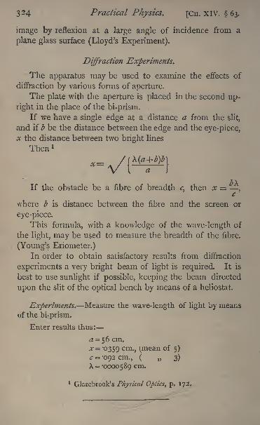
324 Practical Physics. [CH. XIV. 63.
image by reflexion at a large angle of incidence from a
plane glass surface (Lloyd's Experiment).
Diffraction Experiments.
The apparatus may be used to examine the effects of
diffraction by various forms of aperture.
The plate with the aperture is placed in the second up-
right in the place of the bi-prism.
If we have a single edge at a distance a from the slit,
and if b be the distance between the edge and the eye-piece,
x the distance between two bright lines
Then l
*--/{If the obstacle be a fibre of breadth c, then x
,
where b is distance between the fibre and the screen or
eye-piece.
This formula, with a knowledge of the wave-length of
the light, may be used to measure the breadth of the fibre.
(Young's Eriometer.)In order to obtain satisfactory results from diffraction
experiments a very bright beam of light is required. It is
best to use sunlight if possible, keeping the beam directed
upon the slit of the optical bench by means of a heliostat.
Experiments. Measure the wave-length of light by meansof the bi-prism.
Enter results thus:
a = 56 cm.
*"= *359 cm -} (mean of 5)
c = -092 cm., ( 3)
X = -0000589 cm.
1 Glazebrook's Physical Optics, p. 172.
325
CHAPTER XV.
POLARISED LIGHT.
On the Determination of the Position of the Plane ofPolarisation?
THE most important experiments to be made with polarised
light consist in determining the position of the plane of
polarisation, or in measuring the angle through which that
plane has been turned by the passage of the light througha column of active substance, such as a solution of sugar,
turpentine, or various' essential oils, or a piece of quartz.
The simplest method of making this measurement is bythe use of a Nicol's or other polarising prism. This is
mounted in a cylindrical tube which is capable of rotation
about its own axis. A graduated circle is fixed with its
centre in the axis of the tube, and its plane at right
angles to the axis, and a vernier is attached to the tube
and rotates with it, so that the position, with reference
to the circle, of a fiducial mark on the tube can be found.
In some cases the vernier is fixed and the circle turns with
the Nicol. If we require to find the position of the plane
of polarisation of the incident light, we must, of course,
know the position of the principal plane of the Nicol
relatively^ to the circle. If we only wish to measure a rota-
tion a knowledge of the position of this plane is unnecessary,for the angle turned through by the Nicol is, if our adjust-
ments be right, the angle turned through by the plane of
polarisation.
For accurate work two adjustments are necessary :
(1) All the rays which pass through the Nicol should be
parallel.
(2) The axis of rotation of the Nicol should be parallel
to the incident light.
To secure the first, the source of light should be small;1 See Glazebrook, Physical Optics^ chap. xiv.
326 Practical Physics. [CH. XV. 63.
in many cases a brightly illuminated slit is the best. It
should be placed at the principal focus of a convex lens;
the beam emerging from the lens will then consist of
parallel rays.
To make the second adjustment we may generally
consider the plane ends of the tube which holds the Nicol
as perpendicular to the axis of rotation. Place a plate of
glass against one of these ends and secure it in this position
with soft wax or cement. The incident beam falling on
this plate is reflected by it. Place the plate so that this
beam after reflexion retraces its path. This is not a difficult
matter; if, however, special accuracy is required, cover the
lens from which the rays emerge with a piece of paperwith a small hole in it, placing the hole as nearly as maybe over the centre of the lens. The light coming throughthe hole is reflected by the plate, and a spot of light is
seen on the paper. Turn the Nicol about until this spot
coincides with the hole;then the incident light is evi-
dently normal to the plate that is, it is parallel to the axis
of rotation of the Nicol.
If still greater accuracy be required, the plate of glass maybe dispensed with, and a reflexion obtained from the front face
of the Nicol. This, of course, is not usually normal to the
axis, and hence the reflected spot will never coincide with the
hole, but as the Nicol is turned, it will describe a curve on
the screen through which the hole is pierced. If the axis,
of rotation have its proper position and be parallel to the
direction of the incident light, this curve will be a circle
with the hole as centre. The Nicol then must be adjusted
until the locus of the spot is a circle with the hole as centre.
When these adjustments are completed, if the incident
light be plane-polarised, and the Nicol turned until there is
no emergent beam, the plane of polarisation is parallel to
the principal plane of the Nicol;
and if the plane of
polarisation be rotated and the Nicol turned again till the
emergent beam is quenched, the angte turned through by
Cn. XV. 6$.] Polarised Light. 327
the Nicol measures the angle through which the plane of
polarisation has been rotated.
But it is difficult to determine with accuracy the
position of the Nicol for which the emergent beam is
quenched. Even when the sun is used as a source of light,
if the Nicol be placed in what appears to be the positionof total extinction, it may be turned through a considerable
angle without causing the light to reappear. The best
results are obtained by using a very bright narrow line of
light as the source the filament of an incandescence lamphas been successfully employed by Mr. McConnel as the
Nicol is turned, a shadow will be seen to move across this
line from one end to the other, and the darkest portion of
the shadow can be brought with considerable accuracyacross the centre of the bright line. Still, for many pur-
poses, white light cannot be used, and it is not easy to
secure a homogeneous light of sufficient brightness. Twoprincipal methods have been devised to overcome the
difficulty ;the one depends on the rotational properties of
a plate of quartz cut normally to its axis;the other, on the
fact that it is comparatively easy to determine when two
objects placed side by side are equally illuminated if the illu-
mination be only faint. We proceed to describe the twomethods.
64. The Bi-quartz.
If a plane-polarised beam of white light fall on a plateof quartz cut at right angles to its axis, it has, as we have
said, its plane of polarisation rotated by the quartz. But,in addition to this, it is found that the rays of different wave-
lengths have their planes of polarisation rotated throughdifferent angles. The rotation varies approximately inverselyas the square of the wave-length; and hence, if the quartz beviewed through another Nicol's prism, the proportion of
light which can traverse this second Nicol in any positionwill be different for different colours, and the quartz will
appear coloured. Moreover, the colour will vary as the
328 Practical Physics. [Cn. XV. 64.
analysing Nicol, through which the quartz is viewed, is turned
round. If the quartz be about 3*3 mm. in thickness, for
one position of the Nicol it will appear of a peculiar neutral
grey tint, known as the tint of passage. A slight rotation in
one direction will make it red, in the other blue. After a little
practice it is easier to determine, even by eye, when this
tint appears, than to feel certain when the light is completely
quenched by a Nicol. It can be readily shewn moreover
that when the quartz gives the tint of passage, the most
luminous rays, those near the Fraunhofer line E, are wantingfrom the emergent beam
;and if the quartz have the thick-
ness already mentioned, the plane of polarisation of these
rays has been turned through 90.A still more accurate method of making the observation
is afforded by the use of a bi-quartz. Some specimens of
quartz produce a right-handed, others a left-handed rotation
of the plane of polarisation of light traversing them. A bi-
quartz consists of two semicircular plates of quartz placedso as to have a common diameter. The one is right-
handed, the other left. The two plates are of the same
thickness, and therefore produce the same rotation, thoughin opposite directions, in any given ray. If, then, plane-
polarised white light pass normally through the bi-quartz, the
rays of different refrangibilities are differently rotated, and
that too in opposite directions by the two halves, and if the
emergent light be analysed by a Nicol, the two halves will
appear differently coloured. If, however, we place the
analysing Nicol so as to quench in each half of the bi-quartz
the ray whose plane of polarisation is turned through 90that is to say, with its principal plane parallel to that of the
polariser light of the same wave-length will be absent from
both halves of the field, and the other rays will be presentin the same proportions in the two; and if the thickness of
the bi-quartz be about 3*3 mm. this common tint will be the
tint of passage. A very slight rotation of the analyser in
one direction renders one half red, the other blue, while if
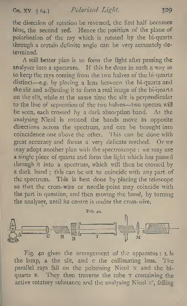
CH. XV. 64.] Polarised Light. 329
the direction of rotation be reversed, the first half becomes
blue, the second red. Hence the position of the plane of
polarisation of the ray which is rotated by the bi-quartz
through a certain definite angle can be very accurately de-
termined.
A still better plan is to form the light after passing the
analyser into a spectrum. If this be done in such a way as
to keep the rays coming from the two halves of the bi-quartz
distinct e.g. by placing a lens between the bi-quartz and
the slit and adjusting it to form a real image of the bi-quartz
on the slit, while at the same time the slit is perpendicularto the line of separation of the two halves two spectra will
be seen, each crossed by a dark absorption band. As the
analysing Nicol is rotated the bands move in opposite
directions across the spectrum, and can be brought into
coincidence one above the other. This can be done with
great accuracy and forms a very delicate method. Or we
may adopt another plan with the spectroscope : we may use
a single piece of quartz and form the light which has passed
through it into a spectrum, which will then be crossed bya dark band
; this can be set to coincide with any part of
the spectrum. This is best done by placing the telescopeso that the cross-wire or needle-point may coincide with
the part in question, and then moving the band, by turningthe analyser, until its centre is under the cross-wire.
FIG. 40.
i-J u m fcl
Fig. 40 gives the arrangement of the apparatus : L is
the lamp, A the slit, and c the collimating lens. The
parallel rays fall on the polarising Nicol N and the bi-
quartz B. They then traverse the tube T containing the
active rotatory substance and the analysing Nicol N', falling

330 Practical Physics. [CH. XV. 64.
on the lens M which forms an image of the bi-quartzon the slit s of the small direct-vision spectroscope. If wewish to do without the spectroscope, we can remove both it
and the lens M and view the bi-quartz either with the naked
eye or with a lens or small telescope adjusted to see it
distinctly. If we use the single quartz, we can substitute
it for the bi-quartz, and focus the eye-piece of the telescopeto see the first slit A distinctly, and thus observe the tint of
passage.
The quartz plate may be put in both cases at either endof the tube T. If it be placed as in the figure, and the
apparatus is to be used to measure the rotation produced
by some active substance, the tube should in the first in-
stance be filled with water, for this will prevent the neces-
"sity of any great alteration in the adjustment of the lens Mor in the focussing of the telescope, if the lens be not used,
between the two parts of the experiment.The mode of adjusting the Nicols has been already
described.
The light should traverse the quartz parallel to its axis,
and this should be at right angles to its faces. This last
adjustment can be made by the same method as was used
for placing the axis of the Nicol in the right position, pro-vided the maker has cut the quartz correctly. In practice
it is most convenient to adjust the quartz by hand, until the
bands formed are as sharp and clear as may be.
Care must be taken that each separate piece of the
apparatus is securely fastened down to the table to prevent
any shake or accidental disturbance.
If a lens is used at M, it is best to have it secured to the
tube which carries the analysing Nicol, its centre being on
the axis of this tube; by this means it is fixed relatively to
the Nicol, and the light always comes through the same
part of the lens. This is important, for almost all lenses
exert a slight depolarising effect on light, which differs ap-
preciably in different parts of the lens. For most purposes
CIT. XV. 64.] Polarised Light. 331
this is not very material, so long as we can be sure that the
effect remains the same throughout our observations. This
assurance is given us, provided that the properties of the
lens are not altered by variations of temperature, if the lens
be fixed with reference to the principal plane of the analyser,
so that both lens and analyser rotate together about a
common axis.
One other point remains to be noticed. If equality of
tint be established in any position, and the analyser be then
turned through 180, then, if the adjustments be perfect,
there will still be equality of tint. To ensure accuracy weshould take the readings of the analysing Nicol in both
these positions. The difference between the two will pro-
bably not be exactly 180;
this arises mainly from the fact
that the axis of rotation is not accurately parallel to the
light. The mean of the two mean readings will give a
result nearly free from the error, supposing it to be small,
which would otherwise arise from this cause.
To attain accuracy in experiments of this kind needs
considerable practice.
Experiments*
(1) Set up the apparatus and measure the rotation producedby the given plate of quartz.
(2) Make solutions of sugar of various strengths, and verifythe law that the rotation for light of given wave-length varies
as the quantity of sugar in a unit of volume of the solution.
Enter results thus:
Thickness of quartz :
roi cm. i -oi 2 cm. roil cm. Mean roil cm.
Analyser readings without quartz plate.
Position A Position B
6 7' 186 10'
6 9 186 12'
6 8' i 86 9'
6 6' 186 ii'
Mean 6 7' 30" Mean 186 10' 30
Mean of the two . 96 9'
332 Practical Physics. [Cn. XV. 64.
Analyser readings with quartz plate.
Position A Position R
280 47' 360 + 100 48'280 45' + 100 47'280 46' 100 49'280 48' 100 50'
Mean 280 46' 30" Mean 360+100 48' 30"
Mean of the two 370 47' 30Mean rotation 274 38 30Rotation deduced from position A . 274 39' o
7'
>, B . 274 38' o"
65. Shadow Polarimeters.
The theory of these, as has been stated, all turns on the
fact that it is comparatively easy to determine when two
objects placed side by side are equally illuminated, the
illumination being faint
Suppose, then, we view through a small telescope or
eye-piece placed behind the analyser a circular hole divided
into two parts across a diameter, and arranged in such a
way that the planes of polarisation of the light emergingfrom the two halves are inclined to each other at a small
angle. For one position of the analyser one half of the
field will be black, for another, not very different, the other
half will be black, and for an intermediate position the two
halves will have the same intensity. The analyser can be
placed with the greatest nicety in the position to producethis. If now the planes of polarisation of the light from
the two halves of the field be each rotated through anythe same angle and the analyser turned until equality of
shade is re-established, the angle through which the analyserturns measures the angle through which the plane of polari-
sation has been rotated.
Whatever method of producing the half-shadow field be
adopted, the arrangement of apparatus will be similar to
that shewn infig. 40, only E will be the half-shadow plate,
CH. XV. 65]. Polarised Light. 333
and instead of the lens M and the spectroscope s we shall
have a small telescope adjusted to view the plate B.
In nearly all cases homogeneous light must be used for
accurate work. Excellent results can be obtained by placing
a bead of sodium on a small spoon of platinum gauze just
inside the cone of a Bunsen burner, and then allowing a jet
of oxygen to play on the gauze.
Lord Rayleigh has found that a good yellow light is
given by passing the gas supplied to a Bunsen burner
through a small cylinder containing a finely divided salt of
sodium, keeping the cylinder at the same time in a state of
agitation, while Dr. Perkin passes the gas over metallic
sodium in an iron tube which is kept heated. The brilliancy
of the light is much increased by mixing oxygen with the
coal gas as in the oxyhydrogen light.
Whenever a sodium flame is used, it is necessary that
the light should pass through a thin plate of bichromate of
potassium, or through a small glass cell containing a dilute
solution of the same salt, to get rid of the blue rays from the
gas.
In almost all cases the half-shadow arrangement maybe attached to either the polariser or the analyser. If the
latter plan be adopted, it must, of course, turn with the
analyser, and this is often inconvenient ; the other arrange-
ment, as shewn in fig. 40, labours under the disadvantagethat the telescope requires readjusting when the tube with
the rotating liquid is introduced.
We will mention briefly the various arrangements which
have been suggested* for producing a half-shadow field,
premising, however, that as the sensitiveness depends both
on the brightness of the light and the angle between the
planes of polarisation in the two halves of the field, it is
convenient to have some means of adjusting the latter.
With a bright light this angle may conveniently be about 2.
It is also important that the line of separation between
1 See also Glazebrook, Physical Optics, chap. xiv.
334 Practical P/iysics. [Cn. XV. 65.
the two halves should be very narrow, and sharp, anddistinct.
(1) Jellett's prism :
The ends of a long rhomb of spar are cut' off at right
angles to its length, and then the spar cut in two by a plane
parallel to its length and inclined at a small angle to the
longer diagonal of the end-face. One half is turned through1 80 about an axis at right angles to this plane, and the two
are reunited.
If a narrow beam of parallel rays fall normally on one
end of such an arrangement, the ordinary rays travel straight
through without deviation, but their planes of polarisationin the two halves are inclined to each other at a small angle.
The extraordinary rays are thrown off to either side of the
apparatus, and if the prism be long enough and the beam not
too wide, they can be separated entirely from the ordinary
rays and stopped by a diaphragm with a small circular hole
in it through which the ordinary rays pass.
(2) Cornu's prism :
A Nicol or other polarising prism is taken and cut in
two by a plane parallel to its length. A wedge-shaped
piece is cut off one half, the edge of the wedge being
parallel to the length of the prism, and the angle of the
wedge some 3. The two are then reunited, thus formingtwo half-Nicols, with their principal planes inclined at a
small angle. The light emerging from each half is plane-
polarised, the planes being inclined at a small angle.
Both of these suffer from the defects that the angle
between the planes of polarisation is fixed and that the sur-
face of separation of the two halves being considerable,
unless the incident light is very strictly parallel, some is
reflected from this surface, and hence the line of separation
is indistinct and ill-defined.
(3) Lippich's arrangement :
The polariser is a Clan's prism. Lippich finds this more

CH. XV. 65.] Polarised Light. 335
convenient than a Nicol, because of the lateral displacement
of the light produced by the latter.
A second Glan's prism is cut in two by a plane parallel
to its length, and placed so that half the light from the first
prism passes through it, while the other half passes at one
side. The first prism is capable of rotation about an axis
parallel to its length, and is placed so that, its principal plane
is inclined at a small angle, which can be varied at will,
to that of the half-prism. The plane of polarisation of the
rays which emerge from this half-prism is therefore slightly
inclined to that of the rays which pass to one side of it,
and this small angle can be adjusted as may be required.
This arrangement also has the disadvantage that the
surface of separation is large, and therefore the line of
division is apt to become indistinct.
(4) Lippich has used another arrangement, which re-
quires a divided lens for either the telescope or collimator,
and is, in consequence, somewhat complicated, though in
his hands it has given most admirable results.
All these four arrangements can be used with white
light, and are therefore convenient in all cases in which the
rotatory dispersion produced by the active substance, due
to variation of wave-length in the light used, is too small
to be taken into account.
(5) Laurent's apparatus :
The polariser is a Nicol followed by a half-wavejjlate
for sodium light, made of quartz or some other crystal.
If quartz cut parallel to the axis be used, the thickness of
the plate will be an odd multiple of '0032 cm. One of the
axes of this plate is inclined at a small angle to the principal
plane of the Nicol. The plate is semicircular in form and
covers half the field half the light passes through it, the
other half, to one side. The light on emerging from the
plate is plane-polarised, and its plane of polarisation is in-
clined to the axis of the quartz at the same angle as that of
33^ Practical Physics. [Cn. XV. 65.
the incident light, but on the opposite side of that axis. Wehave thus plane-polarised light in the two halves of the
field the angle between the two planes of polarisation
being small.
And, again, by varying the angle between the axis of
the quartz and the plane of polarisation of the incident
light, we can make the angle between the planes of polarisa-
tion in the two halves of the field anything we please ; but,
on the other hand, since the method requires a half-wave
plate, light of definite refrangibility must be used.
(6) Poynting's method :
Poynting suggested that the desired result might be
obtained by allowing the light from one half the field, after
traversing a Nicol's prism, to pass through such a thickness
of some rotatory medium as would suffice to produce in its
plane of polarisation a rotation of 2 or 3. If quartz cut
perpendicular to the axis be used, this will be about
01 cm. for sodium light. A plate of quartz so thin as
this being somewhat difficult to work, Poynting suggestedthe use of a thicker plate which had been cut in two ; one
half of this thicker plate is reduced in thickness by about
01 cm., and the two pieces put together again as before ;
the light from one half the field traverses *oi cm. of quartz
more than the "other, and hence the required effect is pro-
duced. This works well, but it is important that the light
should pass through both plates of quartz parallel to the
axis, otherwise elliptic polarisation is produced. Moreover,
the difficulty of obtaining a plate of quartz -01 cm. thick
is not really very great.
Another suggestion of Poynting's was to use a glass cell
with a solution of sugar or other active substance in it. Apiece of plate glass of 3 or 4 mm. in thickness is placed in
the cell, the edge of the plate being flat and smooth. The
polarised light from half the field passes through the 'glass
plate, that from the other half traverses an extra thickness of
some 3 or 4 mm. of su^ar soluliuu, which rulal.es it through
Cn. XV. 65.] Polarised Light. 337
the required angle. This method has an advantage over
the quartz that we are able to adjust the angle between the
planes of polarisation in the two halves of the field by vary-
ing the strength of the solution. Its simplicity is a strong
point in its favour. It has the disadvantage that it is rather
difficult to get a clear sharp edge, but care overcomes this.
Of course the adjustments necessary in the position of
the Nicols, the method of taking the readings, &c., are the
same as those in the last section.
Experiment. Set up a half-shadow polarimeter and mea-
sure the rotation produced in active solutions of various
strengths, determining the relation between the strength of the
solution and the rotation.
Enter results as in preceding section.
CHAPTER XVI.
COLOUR VISION. 1
66. The Colour Top.
THIS apparatus consists of a spindle, which can be
rapidly rotated by means of a pulley fixed to it, and from
this a string or band passes to the driving wheel of some
motor. 2 A disc whose edge is graduated in one hundred
parts turns' with the spindle, and by means of a nut and
washer on the end of the spindle, coloured discs can be
fixed against this divided circle. From six coloured papers
black, white, red, green, yellow, and blue discs of two sizes
are prepared and are then slit along a radius from circum-
ference to centre so as to admit of being slipped one over
the other. Each has a hole at the centre through which
the spindle can pass.
The apparatus is arranged to shew that, if any five out1 See Deschanel, Natural Philosophy, chap. Ixiii.2 The water motor referred to in 28 is very convenient for this
experiment.
Z
33^ Practical Physics. [Cn. XVI. 66.
of these six discs be taken, a match or colour equationbetween them is possible. For instance, if yellow be ex-
cluded, the other five may be arranged so that a mixture of
red, green, and blue is matched against one of black andwhite. Take, then, the three large discs of these colours and,
slipping them one on the other, fix them against the graduatedcircle. Start the motor and let it rotate rapidly, looking at
the discs against a uniform background of some neutral tint.
The three colours will then appear blended into one.
Now place the small discs on these; then on rotatingthe whole, it will be found that the white and black blend
into a grey tint. By continual adjustments an arrangement
may be found, after repeated trials, such that the colour of
the inner circle is exactly the same both in tint and
luminosity as that of the outer ring. The quantities of
colour exposed may then be read off on the graduated
circle, and it will be found that the proportions are some-
what like the following : 79 parts black and 21 white match
29-2 blue, 29*2 green, and 41*6 red.
With the six discs six equations of this kind can be
formed leaving out each colour in turn.
But, according to Maxwell's theory of colour, a match
can be found between any four colours, either combiningthem two -and two in proper proportions, or one againstthree. The colour top is not suited to shew this, for with it wehave another condition to fulfil. The whole circumference
of the circles has in each case to be filled up with the
discs. The vacant spaces must therefore be filled up with
black, which alters the intensity of the resultant tints; but
the intensity may be adjusted by altering the sizes of all the
coloured sectors proportionately, and hence with any four
colours and black a match can be made.
And thus from the theory the six final equations are not
independent ; for between any four of the variables, the
colours, there exists a fixed definite relation. If, then, we
take two of the equations, we can by a simple algebraical
calculation find the others. A^omparison between the
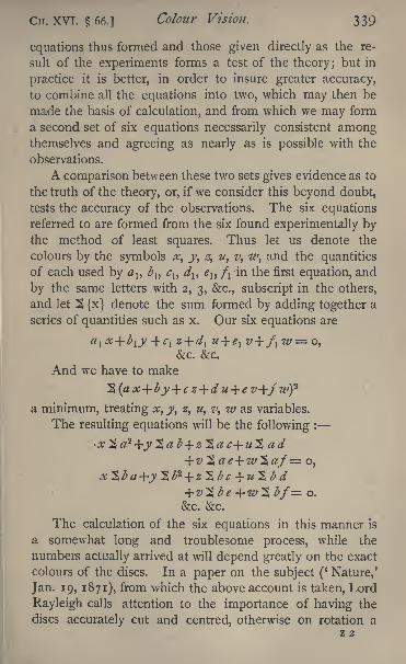
Cn. XVI. 66.] Colour Vision. 339
equations thus formed and those given directly as the re-
sult of the experiments forms a test of the theory; but in
practice it is better, in order to insure greater accuracy,
to combine all the equations into two, which may then be
made the basis of calculation, and from which we may form
a second set of six equations necessarily consistent amongthemselves and agreeing as nearly as is possible with the
observations.
A comparison between these two sets gives evidence as to
the truth of the theory, or, if we consider this beyond doubt,
tests the accuracy of the observations. The six equationsreferred to are formed from the six found experimentally bythe method of least squares. Thus let us denote the
colours by the symbols x, y, z, u, v, w, and the quantities
of each used by 1} b c\, d^ e{9 /i in the first equation, and
by the same letters with 2, 3, &c., subscript in the others,
and let $ {x} denote the sum formed by adding together a
series of quantities such as x. Our six equations are
cl z+d\ u+e l
&c. &c.
And we have to make
a minimum, treating x, y, z, u, v, w as variables.
The resulting equations will be the following :
= o.
&c. &c.
The calculation of the six equations in this manner is
a somewhat long and troublesome process, while the
numbers actually arrived at will depend greatly on the exact
colours of the discs. In a paper on the subject (' Nature,'
Jan. 19, 1871), from which the above account is taken, Lord
Rayleigh calls attention to the importance of having the
discs accurately cut and centred, otherwise on rotation a
Z 2
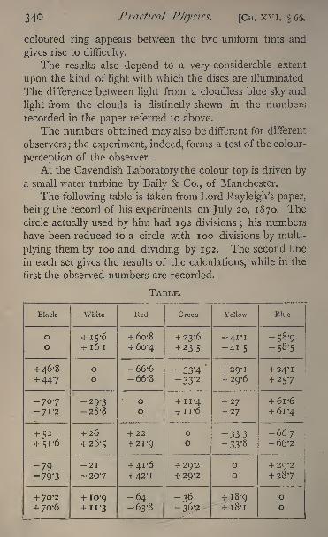
340 Practical Physics. [Cn. XVI.
coloured ring appears between the two uniform tints and
gives rise to difficulty.
The results also depend to a very considerable extent
upon the kind of light with which the discs are illuminated
The difference between light from a cloudless blue sky and
light from the clouds is distinctly shewn in the numbers
recorded in the paper referred to above.
The numbers obtained may also be different for different
observers; the experiment, indeed, forms a test of the colour-
perception of the observer.
At the Cavendish Laboratory the colour top is driven by
a small water turbine by Baily & Co., of Manchester.
The following table is taken from Lord Rayleigh's paper,
being the record of his experiments on July 20, 1870. Thecircle actually used by him had 192 divisions
;his numbers
have been reduced to a circle with 100 divisions by multi-
plying them by 100 and dividing by 192. The second line
in each set gives the results of the calculations, while in the
first the observed numbers are recorded.
TABLE.
Black
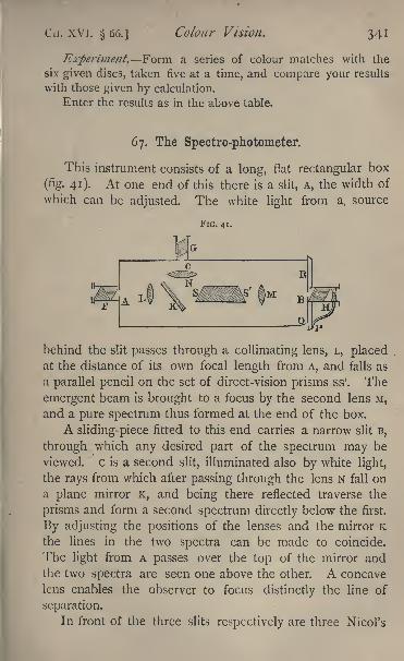
Cii. XVI. 66.] Colour Vision. 341
Experiment. Form a series of colour matches with the
six given discs, taken five at a time, and compare your results
with those given by calculation.
Enter the results as in the above table.
67. The Spectro-photometer.
This instrument consists of a long, flat rectangular box
(fig. 41)- At one end of this there is a slit, A, the width of
which can be adjusted. The white
FIG. 41.
light from a. source
G
behind the slit passes through a collimating lens, L, placedat the distance of its own focal length from A, and falls as
a parallel pencil on the set of direct-vision prisms ss'. The
emergent beam is brought to a focus by the second lens M,
and a pure spectrum thus formed at the end of the box.
A sliding-piece fitted to this end carries a narrow slit B,
through^
which any desired part of the spectrum may be
viewed, c is a second slit, illuminated also by white light,
the rays from which after passing through the lens N fall on
a plane mirror K, and being there reflected traverse the
prisms and form a second spectrum directly below the first.
By adjusting the positions of the lenses and the mirror Kthe lines in the two spectra can be made to coincide.
The light from A passes over the top of the mirror andthe two spectra are seen one above the other. A concave
lens enables the observer to focus distinctly the line of
separation.
In front of the three slits respectively are three Nicol's
342 Practical Physics. [CH. XVI. 67.
prisms, F, G, H. F is fixed with its principal plane vertical,
parallel, therefore, to the slits and edges of the prisms ;G has
its principal plane horizontal, while H is capable of rotation
round a horizontal axis parallel to the length of the box ;
p is a pointer fixed to the prism H and moving over a
graduated circle Q R, which is divided into 360 parts. Thezero of the graduations is at the top of the circle, and whenthe pointer reads zero the principal plane of H is vertical.
The Nicols F and G polarise the light coming throughthe slits, the first in the horizontal plane, the second in the
vertical. The emergent beam is analysed by the Nicol H.
When the pointer reads zero or 180 all the light in the
upper spectrum from the slit A passes through H, but none
of that from c is transmitted. As the Nicol is rotated
through 90 the quantity of light from A which is transmitted
decreases, while the amount coming from c increases, and
when the Nicol has been turned through 90 all the light
from c is transmitted and none from A.
For some position then between o and 90 the bright-
ness of the small portions of the two spectra viewed will be
the same. Let the reading of the pointer when this is the
case be 6. Let the amplitude of the disturbance from A be
a, that of the disturbance from c be c, then clearly
a cos = c sin 0,
and if Ia, I, be the respective luminous intensities,
Now place anywhere between L arid K a small rectan-
gular cell containing an absorbing solution. The upper
spectrum will become darker and the Nicol will require to be
moved to establish equality again in the brightness. Let &be the new reading, and I'a the intensity of the light which
now reaches the eye from A. Then L
~a= tan26'.
*c
1 See Glazebrook, Physical Optics, pp. 10-27.
CH. XVI. 67.] Colour Vision. 343
Thus
rg= tan2 &
17 tan2'
But if k represent the fraction of the light lost by absorp-
tion and reflexion at the faces of the vessel, we have
Hence
tuft'
To eliminate the effects of the vessel the experiment
should be repeated with the vessel filled with water or some
other fluid for which the absorption is small; the difference
between the two results will give the absorption due to the
thickness used of the absorbing medium.
Of course in all cases four positions of the Nicol can be
found in which the two spectra will appear to have the same
intensity. At least two of these positions which are not at
opposite ends of the same diameter should be observed
and the mean taken. In this manner the index error of
the pointer or circle will be eliminated.
For success in the experiments it is necessary that the
sources of light should be steady throughout. In the experi-
ments recorded below two argand gas-burners with ground-
glass globes were used. The apparatus and burners must
remain fixed, relatively to each other, during the observa-
tions.1
Mr. Lea has recently suggested another method of using
the instrument to compare the concentration of solutions of
the same substance of different strengths.
A cell is employed with parallel faces, the distance
between which can be varied at pleasure. A standard solu-
tion of known strength is taken and placed in a cell of
known thickness;
let c{be the concentration, that is, the
1 See Proc. Cam. Phil. Soc.> vol. iv. Part VI. (Glazebrook on a
Spectro-photometer).
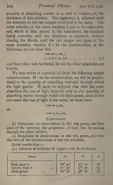
344 Practical Physics. [CH. XVI. 67.
quantity of absorbing matter in a unit of volume, ;//, the
thickness of this solution. The apparatus is adjusted until
the intensity in the two images examined is the same. Theother solution of the same medium is put in the adjustable
cell, which is then placed in 'the instrument, the standard
being removed, and the thickness is adjusted, without
altering the Nicols, until the two images are again of the
same intensity, whence, if c be the concentration, m the
thickness, we can shew that
cm = c\ m\ ;
.*. c clm
l lm (i)
and from this c can be found, for all the other quantities are
known.
We may arrive at equation (i) from the following simple
considerations. If c be the concentration, cm will be propor-
tional to the quantity of absorbing material through which
the light passes. If, then, we suppose that with the same
absorbent the loss of light depends only on the quantity of
absorbing matter through which the light passes, since in the
two cases the loss of light is the same, we must have
cm = c^m^or
c = clm
l /m.
Experiments.
(1) Determine by observations in the red, green, and blue
parts of the spectrum the proportion of light lost by passing
through the given solution.
(2) Determine by observations in the red, green, and blue
the ratio of the concentration of the two solutions.
Enter results thus :
(i.) Solution of sulphate of copper i cm. in thickness.
Colour
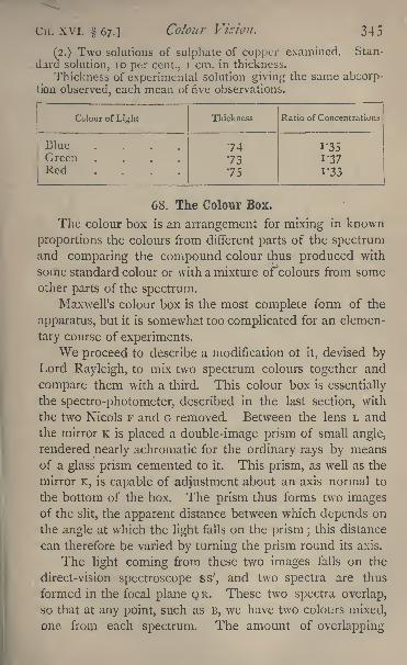
C ii. XVI. 67.] Colour Vision. 345
(2.) Two solutions of sulphate of copper examined. Stan-
dard solution, 10 per cent., I cm. in thickness.
Thickness of experimental solution giving the same abcorp-tion observed, each mean of five observations.
Colour of Light
346 Practical Physics. [CH. XVI. 68.
and therefore the particular colours which are mixed at each
point, depend on the position of the double-image prism,
and, by adjusting this, can be varied within certain limits.
Moreover, on passing through the double image prismthe light from each slit is polarised, and the planes of
polarisation in the two beams are at right angles. We will
suppose that the one is horizontal, the other vertical. Thus,
in the two overlapping spectra the light in one spectrum is
polarised horizontally, in the other vertically. For one
position of the analysing prism the whole of one spectrumis quenched, for another position at right angles to this the
whole of the second spectrum is quenched. The proportion
of light, then, which reaches the eye when the two spectra
are viewed, depends on the position of the analyser, and can
be varied by turning this round. Thus, by rotating the
analyser we can obtain the colour formed by the mixture of
two spectrum colours in any desired proportions, and at the
same time the proportions can be calculated by noting the
position of the pointer attached to the analyser. For if wecall A and B the two colours, and suppose that when the
pointer reads o the whole of the light from A and none of
that from B passes through, and when it reads 90 all the
light from B and none from A is transmitted, while a, /?
denote the maximum brightnesses of the two as they would
reach the eye if the Nicol H were removed, then when the
pointer reads 6 we shall have
Intensity of B _ a
Intensity of A fi
The standard light will be that in the lower part of the
field, which comes from the slit c, after reflexion at the
mirror K. This light being almost unpolarised the re-
flexions and refractions it undergoes slightly polarise it
is only slightly affected in intensity by the motion of the
analyser. By adjusting the tap of the gas-burner we can
alter its intensity, and by turning the mirror K we can bring
any desired portion of the spectrurjMo the point B.
CH. XVI.] Colour Vision, 347
The instrument was designed to shew that a pure yellow,
such as that near the D line, could be matched by a mixture
of red and green in proper proportions, and to measure those
proportions. It is arranged, therefore, in such a way that
the red of one spectrum and the green of the other overlap
in the upper half of the field at B, while the yellow of the
light from c is visible at the same time in the lower half.
Experiment. Determine the proportions of red and green
light required to match the given yellow.
Enter results thus :
Values of Q 5961
60 15'
Mean
Ratio of intensities 3-?.
CHAPTER XVII.
MAGNETISM.
Properties of Magnets.
CERTAIN. bodies, as, for instance, the iron ore called lode-
stone, and pieces of steel which have been subjected to
certain treatment, are found to possess the following pro-
perties, among others, and are called magnets.If a magnet be suspended at any part of the earth's sur-
face, except certain so-called magnetic poles, so as to be free
to turn about a vertical axis, it will in general tend to set itself
in a certain azimuth i.e. with any given vertical plane, fixed
in the body, inclined at a certain definite angle to the geo-
graphical meridian and if disturbed from this position will
oscillate about it.
If a piece of iron or steel, or another magnet, be brought
Practical Physics. [CH. XVII.
near to a magnet so suspended, the latter will be deflected
from its position of equilibrium.If a magnet be brought near to a piece of soft iron or
unmagnetised steel, the iron or steel will be attracted by the
magnet.If a long thin magnetised bar of steel be suspended so
as to be capable of turning about a vertical axis through its
centre of gravity, it will be found to point nearly north and
south. We shall call the end which points north the north
end of the magnet, the other the south end.
DEFINITION OF UNIFORM MAGNETISATION. If a magnetbe broken up into any number of pieces, each of these is
found to be a magnet. Let us suppose that the magnetcan be divided into a very large number of very small, equal,
similar, and similarly situated parts, and that each of the
parts is found to have exactly the same magnetic properties.
The magnet is then said to be uniformly magnetised.
DEFINITION OF MAGNETIC Axis OF A MAGNET. If any
magnet be supported so as to be free to turn in any direc-
tion about its centre of gravity, it is found that there is a
certain straight line in the magnet which always takes up a
certain definite direction with reference to the earth. This
line is called the magnetic axis of the magnet.
DEFINITION OF MAGNETIC MERIDIAN. The vertical
plane through this fixed direction is called the plane of the
magnetic meridian.
DEFINITION OF MAGNETIC POLES. If the magnet be
a long thin cylindrical bar, uniformly magnetised in such a
way that the magnetic axis is parallel to the length of the
bar, the points in which the axis cuts the ends of the bar
are the magnetic poles. The end of the bar which tends to
point north, when the magnet is freely suspended, is the
north9or positive pole ;
the other is the sonth^ or negative
pole. Such a magnet is called solenoidal, and behaves to
other magnets as if the poles were centres of force, the rest
of the magnet being devoid of magnetic action. In all actual
C 1 1. XVII.] Magnetism. 349
magnets the magnetisation differs from uniformity. No two
single points can strictly be taken as centres of force com-
pletely representing the action of the magnet. For manypractical purposes, however, a well-made bar magnet may be
treated as solenoidal with sufficient accuracy ;that is to say,
its action may be regarded as due to two poles or centres of
force, one near each end of the magnet.The following are the laws of force between two mag-
netic poles:
(1) There is a repulsive force between any two like mag-netic poles, and an attractive force between any two unlike
poles.
(2) The magnitude of theforce is in each case numerically
equal to the product of the strength of the poles divided by the
squai'e of the distance between them.
This second law is virtually a definition of the strengthof a magnetic pole.
In any magnet the strength of the positive pole is equalin magnitude, opposite in sign, to that of the negative pole.
If the strength of the positive pole be ;;/, that of the negative
pole is ;;/. Instead of the term 'strength of pole,' the
term '
quantity of magnetism'
is sometimes used. We maysay, therefore, that the uniformly and longitudinally mag-netised thin cylindrical bar behaves as if it had quantities mand m of magnetism at its two ends, north and south
respectively ;we must, however, attach no properties to
magnetism but those observed in the poles of magnets. If,
then, we have two magnetic poles of strengths m and ;', or
two quantities of magnetism m and m', at a distance of
r centimetres apart, there is a force of repulsion between
them which, if m and m' are measured in terms of a proper
unit, is
mm' /r- dynes.
If one of the two m or m' be negative, the repulsionbecomes an attraction.
The C. G. S. unit strength of pole is that of a pole which
35 Practical Physics. [CH. XVII.
repels an equal pole placed a centimetre away with aforce ofone dyne.
In practice it is impossible to obtain a single isolated
pole ;the total quantity of magnetism in any actual magnet,
reckoned algebraically, is always zero.
DEFINITION OF MAGNETIC FIELD. A portion of space
throughout which magnetic effects are exerted by any distri-
bution of magnetism is called the magnetic field due to that
distribution.
Let us consider the magnetic field due to a given dis-
tribution of magnetism. At each point of the field a pole of
strength m is acted on by a definite force. The Resultant
Magnetic Force at each point of the field is the force which
is exerted at that point on a positive pole of unit strength
placed there.
This js also called the Strength of the Magnetic Field at
the point in question.
If H be the strength of the field, or the resultant mag-netic force at any point, the force actually exerted at that
point on a pole of strength m is m H.
The magnetic force at each point of the field will
be definite in direction as well as in magnitude.
DEFINITION OF LINE OF MAGNETIC FORCE. If at any
point of the field a straight line be drawn in the direction
of the magnetic force at that point, that straight line will be
a tangent to the Line of Magnetic Force which passes through
the point. A Line ofMagnetic Force is a line drawn in such
a manner that the tangent to it at each point of its length is
in the direction of the resultant magnetic force at that point.
A north magnetic pole placed at any point of a line of
force would be urged by the magnetic force in the direc-
tion of the line of force.
As we shall see shortly, a small magnet, free to turn
about its centre of gravity, will place itself so that its axis is
in the direction of a line of force.
A surface which at each point is at right angles to the
C 1 1. XVII. ] Magnetism. 3 5 1
line of force passing through that point is called a level
surface or surface of equilibrium, for since the lines of force
are normal to the surface, a north magnetic pole placed
anywhere on the surface will be urged by the magneticforces' perpendicularly to the surface, either inwards or
outwards, and might therefore be regarded as kept in equi-librium by the magnetic forces and the pressure of the
surface. Moreover, if the pole be made to move in any
way over the surface, since at each point of its path the
direction of its displacement is at right angles to the direction
of the resultant force, no work is done during the motion.
DEFINITION OF MAGNETIC POTENTIAL. The magnetic
potential at any point is the work done against the magneticforces in bringing up a unit magnetic pole from the boundaryof the magnetic field to the point in question.
The work done in transferring a unit magnetic pole from
one point to another against magnetic forces is the difference
between the values of the magnetic potential at those points.
Hence it follows that the magnetic potential is the same at
all points of a level surface. It is therefore called an equi-
potential surface.
Let us suppose that we can draw an equipotential surface
belonging to a certain configuration of magnets, and that weknow the strength of the magnetic field at each point of the
surface. Take a small element of area, a square centimetres
in extent^ round any point, and through it draw lines of
force in such a manner that if H be the strength of the
magnetic field at the point, the number of lines of force
which pass through the area a is H a.
Draw these lines so that they are uniformly distributed
over this small area.
Do this for all points of the surface.
Take any other point of the field which is not on this
equipotential surface;draw a small element of a second
equipotential surface round the second point and let its area
be a' square centimetres. This area will, of course, be per-
35 2 Practical Physics. [Cn. xvn.
pendicular to the lines of force vdiich pass through it.
Suppose that the number of lines of force which pass
through this area is',
then it can be proved, as a conse-
quence of the law of force between two quantities of mag-netism, that the strength of the field at any point of this
second small area a! is numerically equal to the ratio n' /a'.
The field of force can thus be mapped out by means of
the lines of force, and the intensity of the field at each
point determined by their aid.
The intensity is numerically equal to the number of lines
of force passing through any small area of an equipotentialsurface divided by the number of square centimetres in that
area, provided that the lines of force have originally been
drawn in the manner described above. 1
1 For an explanation of the method of mapping a field of force bymeans of lines of force, see Maxwell's Elementary Electricity, chaps, v.
and vi, and Cumming's Electricity', chaps, ii. and iii. The necessary
propositions may be summarised thus (leaving out the proofs) :
(l) Consider any closed surface in the field of force, and imaginethe surface divided up into very small elements, the area of one of
which is ff;
let F be the resultant force at any point of &. resolved
normally to the surface inwards ; let 2 F ff denote the result of addingtogether the products F <r for every small elementary area of the closed
surface. Then, if the field offeree be due to matter, real or imaginary,for which the law of attraction or repulsion is that of the inverse squareof the distance,
where M is the quantity of the real or imaginary matter in questioncontained inside the closed surface.
(2) Apply proposition (l) to the case of the closed surface formed
by the section of a tube of force cut off between two equipotential sur-
faces. [A tube of force is the tube formed by drawing lines of force
through every point of a closed curve.]
Suppose ff and ff' are the areas of the two ends of the tube, F and F'
the forces there ; then F <r= F' ff'.
(3) Imagine an equipotential surface divided into a large numberof very small areas, in such a manner that the force at any point is in-
versely proportional to the area in which the point falls. Then ff beina;
"the measure of an area and F the force there, F ff is constant for everyelement of the surface.
(4) Imagine the field of force filled with tubes of force, with the
elementary areas of the equipotential surface of proposition (3) as bases.
These tubes will cut a second equipotential surface in a series of ele-
mentary areas (/. Let F' be force at ff', then by propositions (2) and
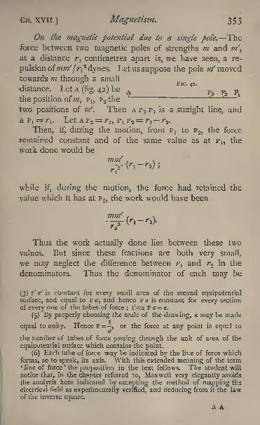
CH. XVII. ] Magnetism. 353
On the magnetic potential due to a single pole. Theforce between two magnetic poles of strengths m and ;;/',
at a distance r{centimetres apart is, we have seen, a re-
pulsion ofmm'Ir^ dynes. Let us suppose the pole m1 moved
towards m through a smallFJG
distance. Let A(fig. 42) be A p3 pa p
the position of;;/, P I} ? 2 the
two positions of ;;/. Then A p.2 P Iis a straight line, and
A P,=/V Let AP 2= r2 ,
ptP 2=
r, r2 .
Then, if, during the motion, from PJ to P 2 ,the force
remained constant and of the same value as at P I} the
work done would be
while if, during the motion, the force had retained the
value which it has at P 2 ,the work would have been
Thus the work actually done lies between these two
values. But since these fractions are both very small,
we may neglect the difference between t\ and r2 in the
denominators. Thus the denominator of each may be
(3) F' a-' is cbnstant for every small area of the second equipotential
surface, and equal to F <r, and hence F a is constant for every section
of every one of the tubes of force;thus F &= K.
(5) By properly choosing the scale of the drawing, K may be made
equal to unity. Hence F =,
or the force at any point is equal toa
the number of tubes of force passing through the unit of area of the
equipotential surface which contains the point.
(6) Each tube offeree may be indicated by the line of force which
forms, so to speak, its axis. With this extended meaning of the term'line of force' the proposition in the text follows. The student will
notice that, in the chapter referred to, Maxwell very elegantly avoids
the analysis here indicated by accepting the method of mapping ths
electrical field as experimentally verified, and deducing from it the lawof the inverse square.
A A
354 Practical Physics. [CH. XVII.
written r^2 instead .of r^ and r<? respectively. The two
expressions become the same, and hence the work done is
or
mm'(i-?-).
Similarly the work done in going from P 2 to a third
point, P3 ,is
And hence we see, by adding the respective elements
together, that the work done in going from a distance r1to
a distance r is
Hence the work done in bringing the pole m from infinity
to a distance r from the pole ;;/ is mm' fr. But the potential
due to m at a distance r, being the work done in bringing
up a unit pole from beyond the influence of the pole m,will be found by dividing this by m' it is therefore equal
to m/r.
Again, it follows from the principle of conservation of
energy that the work done in moving a unit pole from anyone point to any other is independent of the path, and
hence the work done in moving the unit pole from any point
whatever at a distance r1to any point at a distance r from
the pole m is
For a single pole of strength m, the equipotential sur-
faces are clearly a series of concentric spheres, with ;;/ as
centre; the lines of force are radii of these spheres.
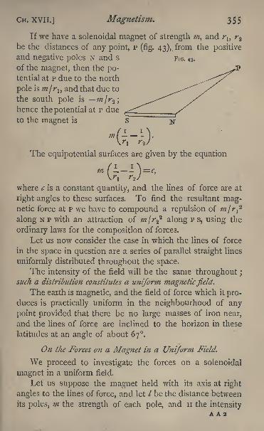
CH. XVI I. ] Magnetism. 355
If we have a solenoidal magnet of strength m, and rl} r^
be the distances of any point, p (fig. 43),. from the positive
and negative poles N and s FIG. 43.
of the magnet, then the po-tential at p due to the north
pole is injrlt and that due to
the south pole is in\r^\
hence the potential at P due
to the magnet is
x- i i.'
The equipotcntial surfaces are given by the equations _ x
m I \=c,ri>
where c is a constant quantity, and the lines of force are at
right angles to these surfaces. To find the resultant mag-netic force at P we have to compound a repulsion of mjr^along NP with an attraction of m\r^ along PS, using the
ordinary laws for the composition of forces.
Let us now consider the case in which the lines of force
in the space in question are a series of parallel straight lines
uniformly distributed throughout the space.
The intensity of the field will be the same throughout ;
such a distribution constitutes a uniform magneticfield.The earth is magnetic, and the field of force which it pro-
duces is practically uniform in the neighbourhood of any
point provided that there be no large masses of iron near,
and the lines of force are inclined to the horizon in these
latitudes at an angle of about 67.
On the Forces on a Magnet in a Uniform Field.
We proceed to investigate the forces on a solenoidal
magnet in a uniform field.
Let us suppose the magnet held with its axis at right
angles to the lines of force, and let / be the distance between
its poles, m the strength of each pole, and H the intensityA A 2
Practical Physics. [CH. XVII.
of the field. The north pole is acted on by a force m H at
right angles to the axis of the magnet, the south pole by an
equal, parallel, but opposite force m H. These two forces
constitute a couple; the distance between the lines of action,
or arm of the couple, is /, so that the moment of the coupleis m I H. If the axis of the magnet be inclined at an angle
to the lines of force, the arm of the couple will be m /sin 0,
and its moment m I H sin 0. In all cases the couple will
depend on the product ml.
DEFINITION OF MAGNETIC MOMENT OF A MAGNET.The product of the strength of either pole into the distance
between the poles, is called the magnetic moment of a
solenoidal magnet Let us denote it by M ;then we see that
if the axis of the magnet be inclined at an angle to the lines
of force, the couple tending to turn the magnet so that its
axis shall be parallel to the lines of force is M H sin 9. Thusthe couple only vanishes when is zero
;that is, when the
axis of the magnet is parallel to the lines of force.
But, as we have said, the actual bar magnets which weshall use in the experiments described below are not strictly
solenoidal, and we must therefore consider the behaviour, in
a uniform field, of magnets only approximately solenoidal.
If we were to divide a solenoidal magnet into an in-
finitely large number of very small, equal, similar, and
similarly situated portions, each of these would have identical
magnetic properties ;each would be a small magnet with a
north pole of strength ;;/ and a south pole of strength m.
If we bring two of these elementary magnets together so
a's to begin to build up, as it were, the original magnet, the
north pole of the one becomes adjacent to the south pole of
the next; we have thus superposed, a north pole of strength
771 and a south pole of strength m\ the effects of the two
at any distant point being thus equal and opposite, no ex-
ternal action can be observed. We have therefore a magnet
equal in length to the sum of the lengths of the other two,
with two poles of the same strength as those of either.
CIT. xvil.] Magnetism. 357
If, however, we were to divide up an actual magnet in
this manner, the resulting elementary magnets would not all
have the same properties.
We may conceive of the magnet, then, as built up of a
number of elementary magnets of equal volume but of dif-
ferent strengths.
Consider two consecutive elements, the north pole of
the one of strength m is in contact with the south pole of
the other of strength m' say ; we have at the point of
junction a north pole of strength mm', we cannot replace
the magnet by centres of repulsive and attractive force at
its two ends respectively, and the calculation of its action
becomes difficult.
If, however, the magnet be a long bar of well-temperedsteel carefully magnetised, it is found that there is very little
magnetic action anywhere except near the ends. The
elementary magnets of which we may suppose it to consist
would have equal strengths until we get near the ends of the
magnet, when they would be found to fall off somewhat. Theaction of such a magnet may be fairly represented by that
of two equal poles placed close to, but not coincident with,
the ends ; and we might state, following the analogy of a
solenoid, that the magnetic moment of such a magnet was
measured by the product of the strength of either pole into
the distance between its poles.
We can, however, give another definition of this quantity
which will apply with strictness to any magnet. The momentof the couple on a solenoidal magnet, with its axis at an
angle to the lines of magnetic force in a field of uniform
intensity H, is, we have seen, M H sin 0, M being the mag-netic moment. Thus the maximum couple which this
magnet can experience is M H, and the maximum couple
which the magnet can be subjected to in a field of uniform
force of intensity unity is M.
Now any magnet placed in a uniform field of magneticforce is acted on by a couple, and we may say that for
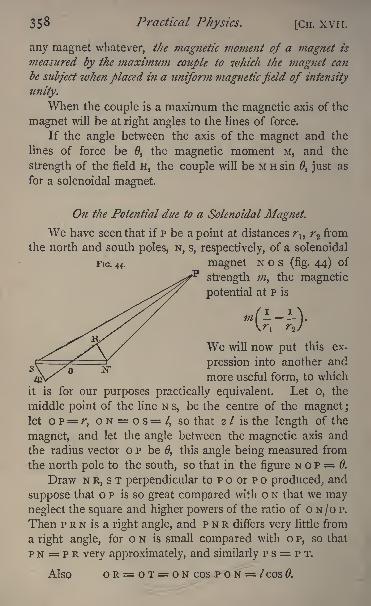
35^ Practical Physics. [CH. XVI I.
any magnet whatever, the magnetic moment of a magnet is
measured by the maximum couple to which the magnet can
be subject when placed in a uniform magneticfield of intensity
unity.
When the couple is a maximum the magnetic axis of the
magnet will be at right angles to the lines of force.
If the angle between the axis of the magnet and the
lines of force be 0, the magnetic moment M, and the
strength of the field H, the couple will be M H sin 0, just as
for a solenoidal magnet.
On the Potential due to a Solenoidal Magnet.
We have seen that if p be a point at distances rlt
r>2 from
the north and south poles, N, s, respectively, of a solenoidal
FJG. 44. magnet N o s (fig. 44) of
strength m, the magnetic
potential at P is
(H>We will now put this ex-
pression into another and
more useful form, to which
it is for our purposes practically equivalent. Let o, the
middle point of the line N s, be the centre of the magnet ;
let o P= r, o N = o s= /, so that 2 / is the length of the
magnet, and let the angle between the magnetic axis and
the radius vector OP be 0, this angle being measured from
the north pole to the south, so that in the figure N o P = 0.
Draw N R, s T perpendicular to P o or p o produced, and
suppose that OP is so great compared with o N that we mayneglect the square and higher powers of the ratio of o N/O P.
Then p R N is a right angle, and p N R differs very little from
a right angle, for ON is small compared with o P, so that
p N = P R very approximately, and similarly p s = P T.
Also OR=OT = ON COS P O N = /COS 0.
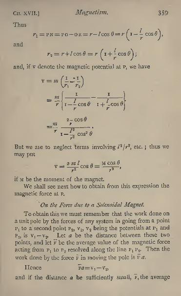
Cn. xvii.] Magnetism. 359
Thus
T-I= PN = PO OR= r I cos = r f i cos
J,
and
r2= T-+/COS = r fi + - cos 0\ ;
and, if v denote the magnetic potential at p, we have
1)1
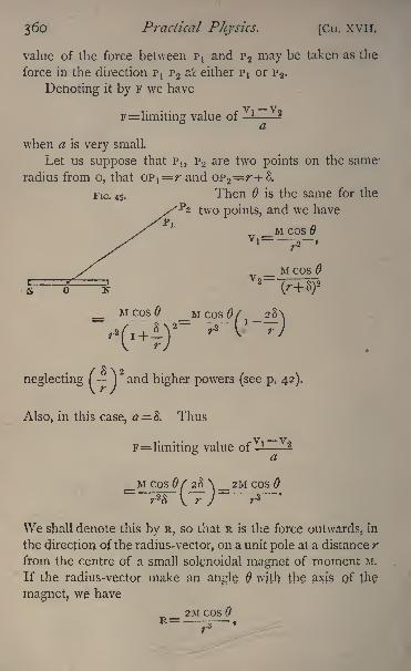
360 Practical Physics. [Cn. XVII.
value of the force between ptand P 2 may be taken as the
force in the direction ptP 2 at either PJ or P 2 ,
Denoting it by F we have
F= limiting value of
when a is very small.
Let us suppose that P,, P 2 are two points on the same:
radius from o, that opl^=r and OP 2 =r-i-S.
FIG. 45. Then is the same for the
two points, and we have
M cos 9
neglecting fjand higher powers (see p. 42).
Also, in this case, a= & Thus
F= limiting; value of -!--
a
COS0
\Ve shall denote this by R, so that R is the force outwards, in
the direction of the radius-vector, on a unit pole at a distance r
from the centre of a small solenoidal magnet of moment M.
If the radius-vector make an angle with the axis pf the
magnet, we have
2M COS
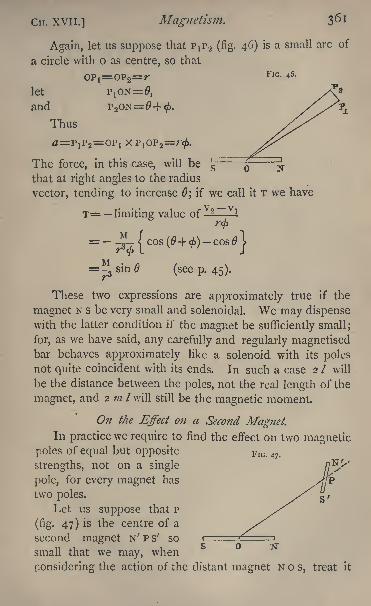
CH. xvii.] Magnetism.
Again, let us suppose that Ptp 2 (fig. 46) is a small arc of
a circle with o as centre, so that
OP =OP =7* FlGl 46>
let PiON=0,and P 2ON=!
Thus
The force, in this case, will be |F
that at right angles to the radius
vector, tending to increase 0; if we call it T we have
T= limiting value of 2~ v
l
=p sin (seep. 45).
These two expressions are approximately true if the
magnet N s be very small and solenoidal. We may dispensewith the latter condition if the magnet be sufficiently small;
for, as we have said, any carefully and regularly magnetisedbar behaves approximately like a solenoid with its polesnot quite coincident with its ends. In such a case 2 I will
be the distance between the poles, not the real length of the
magnet, and 2 ;// /will still be the magnetic moment.
On the Effect on a Second Magnet.In practice we require to find the effect on two magnetic
poles of equal but opposite FlG 47>
strengths, not on a single
pole, for every magnet has
two poles. s/g r
Let us suppose that P
(fig. 47) is the centre of a
second magnet N' P s' so
small that we may, when
considering the action of the distant magnet N o s, treat it
362 Practical Physics. [CH. XVII.
as if either pole were coincident with p, that in! is the
strength, and 2 I' the length of this magnet, and 6' the
angle between p N' and o P produced.Then we have, acting outwards parallel to the radius
vector o P on the pole N', a force
2 m' M cos
and an equal and parallel force acting inwards towards o on
the pole s'; these two constitute a couple, the arm of which
will be 2 /' sin 0'. Thus, if M' be the magnetic moment of
the second magnet, so that M' = 2 m' /Y\ve have acting on
this magnet a couple, tending to decrease 0', whose momentwill be
2 MM' cos sin 0'
r*
This arises from the action of the radial force R.
The tangential force on N' will be
M m' sin
-73
tending to increase 0' and on s' an equal force also tending
to increase it. These constitute another couple tending to
increase 0';the arm of this couple will be 2 /' cos 0', and
its moment will be
M M' sin cos 0'
-73
Thus, combining the two, we shall have a couple, the
moment of which, tending to increase 0', will be
*1-(sin cos 0'-2 sin 0' cos
0).
It must of course be remembered that these expressions
are only approximate ;we have neglected terms which, if
the magnets are of considerable size, may become im-
portant.
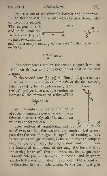
CH. XVII.] Magnetism. 363
Two cases are of considerable interest and importance.In the first the axis of the first magnet passes through the
centre of the second.
The magnet N s isFlG-48 -
said to be ' end on.' , : ,.
In this case (fig. 48)s
we have 6=0, and the
action is a couple tending to decrease 0', the moment of
which is
^l' M- sin &.
If no other forces act on the second magnet, it will set
itself with its axis in the prolongation of that of the first
magnet.In the second case (fig. 49) the line joining the centres
of the two is at right angles to the axis of the first magnet,which is said to be ' broadside on '; then FIG. 49.
= 90, and we have a couple tending to ^increase 0', the moment of which will be
MM 7
COS &. S
We may notice that for a given value
of r, the maximum value of the couple in
this second case is only halfof its maximumvalue in the former case.
'
o 2T
The position of equilibrium will be that in which
cos 6' o, or when the two axes are parallel. Let us sup-
pose that the second magnet is capable of rotating about a
vertical axis through its centre, in the same way as a compassneedle ; it will, if undisturbed, point north and south under
the horizontal component of the magnetic force due to
the earth ; let us call this H. Place the first magnet with
its north pole pointing towards the second, and its centre
exactly to the west of that of the second. The second will
be deflected, its north pole turning to the east Let < be
364 Practical Physics. [CH. XVII.
the angle through which it turns, then clearly & = 90 $.
The moment of the earth's force on the magnet is M'H sin <,
that of the couple due to the other magnet is
2 M M' sin & /r*, or 2 M M' cos <j>/r3
,
in the opposite direction. But the magnet is in equilibriumunder these two couples, and hence we have
M' H sin < = 2 M3
Mcos <.
ThusM = \ H r3 tan 0.
Next place the first magnet with its north pole west and
its centre exactly to the south of the second;the north pole
of the second will move to the east through an angle ^, say,
and in this case we shall have 0' =\j/.
The moment of the couple due to the earth will be as
before M'H sin ^ jthat due to the first magnet is
and hence M = H r 3 tan $.
We shall see shortly how these formulae may be used to
measure M and H.
On tlie Measurement of Magnetic Force.
The theoretical magnets we have been considering are
all supposed to be, in strictness, simply solenoidal rods
without thickness, mere mathematical lines in fact.
The formulae may be applied as a first approximation,
however, to actual magnets, and we shall use them in the
experiments to be described.
There remains, however, for consideration the theory
of an experiment which will enable us to compare the
magnetic moments of a magnet of any form under different
CH. XVII.] Magnetism. 365
conditions of magnetisation, or of two magnets of known
form, or to compare the strengths of two approximatelyuniform magnetic fields, or, finally, in conjunction with the
formulae already obtained, to measure the moment of the
magnet and the strength of the field in which it is.
We have seen (p. 144) that, if a body, whose moment of
inertia about a given axis is K, be capable of vibrating about
that axis, and if the force which acts on the body after it has
been turned through an angle 6 from its position of equi-
librium, tending to bring it back to that position, be //,#,
then the body will oscillate isochronously about this posi-
tion;also if the time of a complete small oscillation be T,
then T is given by the formula
/K= 27rA/Vfj.
We shall apply this formula to the case of a magnet.We have seen already that, if a magnet be free to oscillate
about a vertical axis through its centre of gravity, it will
take up a position of equilibrium with its magnetic axis
in the magnetic meridian. The force which keeps it in
the meridian arises from the horizontal component of the
earth's magnetic force ; and if the magnet be disturbed
from this position through an angle 0, the moment of the
couple tending to bring it back is M H sin 0, M being the
magnetic moment. Moreover, if be the circular measure
of a small angle, we know that the difference between and
sin & depends on $3 and may safely be neglected ; we mayput, therefore, with very high accuracy, if the magnet be
made to oscillate only through a small angle, the value for
sin in the above expression for the moment of the couple
acting on the magnet, which thus becomes M H &; so that, if
K be the moment of inertia of the magnet about the ver-
tical axis, the time of a small oscillation T is given by the
equation
=>VGrH>
366 Practical Physics. [CH. xvil.
T can be observed experimentally, and hence we get an
equation to find M H, viz.
If we have in addition a relation which gives the ratio of
M/H from the two we can find M and H. Such a relation
has been obtained above (p. 364), and with the notation
there employed we have
H
We shall discuss the experimental details shortly.
Magnetic Induction.
There are some substances in which the action of mag-netic forces produces a magnetic state which lasts only as
long as the magnetic forces are acting. Such substances,
of which iron is the most marked example, become them-
selves temporary magnets when placed in a magnetic field.
They are said to be magnetised by induction. They lose
nearly all their magnetic property when the magnetising
forces cease to act. In most specimens of iron a certain
amount of this remains as permanent magnetism after the
cessation of the magnetising forces. In very soft iron the
amount is very small; in steel, on the other hand, the
greater portion remains permanently. We shall call such
substances magnetic.
The attraction between a magnet and a magnetic sub-
stance is due to this induction.
Wherever a line of force from a magnet enters a
magnetic substance it produces by its action a south pole.
Where it leaves the substance it produces a north pole.
Thus, if a magnetic body be brought near a north pole,
those portions of the surface of the body which are turned
towards the body become endued generally with south
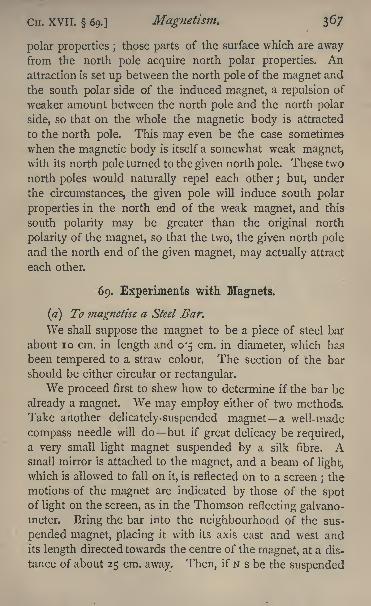
CH. XVII. 69.] Magnetism. 367
polar properties ;those parts of the surface which are away
from the north pole acquire north polar properties. Anattraction is set up between the north pole of the magnet and
the south polar side of the induced magnet, a repulsion of
weaker amount between the north pole and the north polar
side, so that on the whole the magnetic body is attracted
to the north pole. This may even be the case sometimes
when the magnetic body is itself a somewhat weak magnet,with its north pole turned to the given north pole. These two
north poles would naturally repel each other; but, under
the circumstances, the given pole will induce south polar
properties in the north end of the weak magnet, and this
south polarity may be greater than the original north
polarity of the magnet, so that the two, the given north poleand the north end of the given magnet, may actually attract
each other.
69. Experiments with Magnets,
(a) To magnetise a Steel Bar.
We shall suppose the magnet to be a piece of steel bar
about 10 cm. in length and 0-5 cm. in diameter, which has
been tempered to a straw colour. The section of the bar
should be either circular or rectangular.
We proceed first to shew how to determine if the bar be
already a magnet. We may employ either of two methods.
Take another delicately-suspended magnet a well-made
compass needle will do but if great delicacy be required,a very small light magnet suspended by a silk fibre. Asmall mirror is attached to the magnet, and a beam of light,
which is allowed to fall on it, is reflected on to a screen; the
motions of the magnet are indicated by those of the spotof light on the screen, as in the Thomson reflecting galvano-meter. Bring the bar into the neighbourhood of the sus-
pended magnet, placing it with its axis east and west andits length directed towards the centre of the magnet, at a dis-
tance of about 25 cm. away. Then, if N s be the suspended
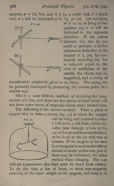
36S Practical Physics. [Cn. XVII. 69,
magnet, N' s' the bar, and if N' be a north end, s' a south
end, N s will be deflected as in fig. 50 (i). On reversing
F.G. 5o. N' s' so as to bring it into
position (2), N s will be
deflected in the opposite
direction. If the action
^/between the two be too
small to produce a visible
permanent deflexion of the
magnet N s, yet, by con-
tinually reversing the bar
at intervals equal to the
time of oscillation of the
needle, the effects may be
magnified, and a swing of
considerable amplitude given to the latter. The swing can
be gradually destroyed by presenting the reverse poles in a
similar way.This is a most delicate method of detecting the mag-
netism of a bar, and there aie few pieces of steel which will
not shew some traces of magnetic action when treated thus.
The following is the second method. Twist a piece of
copper wire to form a stirrup (fig. 51) in which the magnetcan be hung, and suspend it under
a bell-jar by a silk fibre, which mayeither pass through a hole at the
top of the jar and be secured above,or be fixed to the jar with wax or
cement. If the magnet to be used
be rectangular in section,the stirrup
should be made so that one pair of
faces may be horizontal, the other"^" ***'
vertical when swinging. For verydelicate experiments this fibre must be freed from torsion.
To do this take a bar of brass, or other non-magnetic
material, of the same weight as the magnet, and hang it in
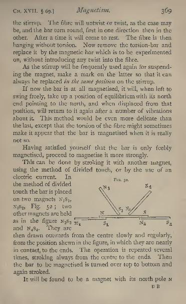
CH. XVII. 69.] Magnetism. 369
the stirrup. The fibre will untwist or twist, as the case maybe, and the bar turn round, first in one direction then in the
other. After a time it will come to rest. The fibre is then
hanging without torsion. Now remove the torsion-bar and
replace it by the magnetic bar which is to be experimented
on, without introducing any twist into the fibre.
As the stirrup will be frequently used again for suspend-
ing the magnet, make a mark on the latter so that it can
always be replaced in the same position on the stirrup.
If now the bar is at all magnetised, it will, when left to
swing freely, take up a position of equilibrium with its north
end pointing to the north, and when displaced from that
position, will return to it again after a number of vibrations
about it This method would be even more delicate than
the last, except that the torsion of the fibre might sometimes
make it appear that the bar is magnetised when it is really
not so.
Having satisfied yourself that the bar is only feebly
magnetised, proceed to magnetise it more strongly.
This can be done by stroking it with another magnet,
using the method of divided touch, or by the use of an
electric current. In
the method of divided
touch the bar is placedon two magnets N^,N2s 2 , Fig. 52; two \\s,other magnets are held
as in the figure N 3s 3=
^ i^T" "^and N4s4 . They are
then drawn outwards from the centre slowly and regularly,
from the position shewn in the figure, in which they are nearly
in contact, to the ends. The operation is repeated several
times, stroking always from the centre to the ends. Then
the bar to be magnetised is turned over top to bottom and
again stroked.
It will be found to be a magnet with its north pole NU B
3/O Practical Physics. [CH. XVII. 69.
over s1and its south pole s over N 2 . In all cases the two
ends of the bar rest on opposite poles, and the poles above,
which are used for stroking, are of the same name as those
below, on which the bar rests. The two magnets used for
stroking should have about the same strength.
If an electric current be used, the bar may be mag-netised either by drawing it backwards and forwards across
the poles of an electro-magnet, or by placing it inside of
a long coil of thick insulated wire, such as is used for the
coils of an electro-magnet, and allowing a powerful current
to pass through the wire.
It will be much more strongly magnetised if it be put
into the coil when hot and allowed to cool with the current
circulating round it
To deprive a steel bar entirely of its magnetism is a
difficult matter. The best plan is to heat it to a red heat
and allow it to cool gradually ^with its axis pointing east and
west. If it be placed north and south, it will be found that
the magnetic action of the earth is sufficient to re-magnetise
the bar.
(fr)To compare the Magnetic Moment of the same Magnet
afttr different Methods of Treatment^ or of two different
Magnets.
(i) Suspend the magnet in its stirrup under the bell
jar, as in fig. 51, and when it is in equilibrium make a mark
on the glass opposite to one end. Displace the magnet
slightly from this position, and count the number of times
the end crosses the mark in a known interval of time,
say one minute a longer interval will be better if the
magnet continue swinging. Divide this number by the
number of seconds in the interval, 60 in the case supposed,the result is the number of transits in one second. Call
this n. There will be two transits to each complete oscilla-
tion, for the period of an oscillation is the interval between
two consecutive passages of the needle through the resting
point in the same direction, and all transits, both right to left
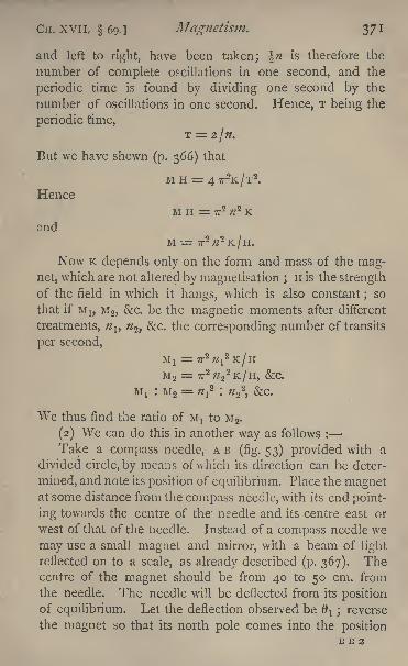
CH. XVII, 69.] Magnetism. 3/1
and left to right, have been taken; \n is therefore the
number of complete oscillations in one second, and the
periodic time is found by dividing one second by the
number of oscillations in one second. Hence, T being the
periodic time,T = 2/.
But we have shewn (p. 366) that
M H = 4 7TK/T2
.
HenceM H = 7T
2;/
2 K
andM -= 7T
2 2K/H.
Now K depends only on the form and mass of the mag-net, which are not altered by magnetisation ; H is the strength
of the field in which it hangs, which is also constant;so
that if M b M 2 ,&c. be the magnetic moments after different
treatments, nlt n^ c. the corresponding number of transits
per second,
MI = 7T2
7;1
2K/H
M 2= 7T
2/2 2
2K/H, &C.
M! : M 2= n^ : ;/ 2
2,&c.
We thus find the ratio of M, to M 2 .
(2) We can do this in another way as follows :
Take a compass needle, AB (fig. 53) provided with a
divided circle, by means of which its direction can be deter-
mined, and note its position of equilibrium. Place the magnetat some distance from the compass needle, with its end point-
ing towards the centre of the needle and its centre east or
west of that of the needle. Instead of a compass needle we
may use a small magnet and mirror, with a beam of light
reflected on to a scale, as already described (p. 367). Thecentre of the magnet should be from 40 to 50 cm. from
the needle. The needle will be deflected from its positionof equilibrium. Let the deflection observed be O
l reverse
the magnet so that its north pole comes into the positionB B 2
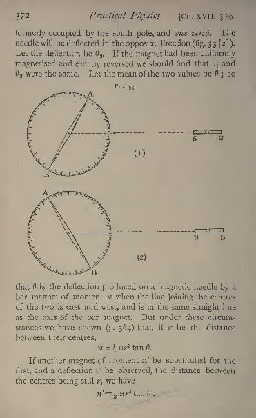
372 Practical Physics. [CH. XVII. 69.
formerly occupied by the south pole, and vice versa. Theneedle will be deflected in the opposite direction (fig. 53 [2]).
Let the deflection be 6 2 . If the magnet had been uniformly
magnetised and exactly reversed we should find that tfj and# 2 were the same. Let the mean of the two values be 6
;so
FIG. 53.
N
(2)
that is the deflection produced on a magnetic needle by a
bar magnet of moment M when the line joining the centres
of the two is east and west, and is in the same straight line
as the axis of the bar magnet. But under these circum-
stances we have shewn (p. 364) that, if r be the distance
between their centres,
M \ Hr3 tan 0.
If another magnet of moment M' be substituted for the
first, and a deflection 0' be observed, the distance between
the centres being still r, we have
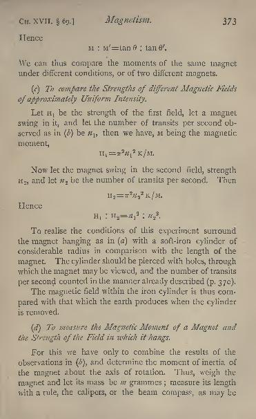
CH. XVII. 69.] Magnetism. 373
HenceM : M'==tanfl : tanfl'.
\Ve can thus compare the moments of the same magnetunder different conditions, or of two different magnets.
(c] To compare the Strengths of different Magnetic Fields
of approximately Uniform Intensity.
Let H! be the strength of the first field, let a magnet
swing in it, and let the number of transits per second ob-
served as in (b) be nlt
then we have, M being the magnetic
moment,
H,=7T2W
1
2K/M.
Now let the magnet swing in the second field, strength
H 2 ,and let ;? 2 be the number of transits per second. Then
H 2= 7T
222K/M.
Hence
H! : H 2=
!
2: ;/ 2
2.
To realise the conditions of this experiment surround
the magnet hanging as in (a) with a soft-iron cylinder of
considerable radius in comparison with the length of the
magnet. The cylinder should be pierced with holes, throughwhich the magnet may be viewed, and the number of transits
per second counted in the manner already described (p. 370).
The magnetic field within the iron cylinder is thus com-
pared with that which the earth produces when the cylinder
is removed.
(d) To measure the Magnetic Moment of a Magnet and
the Strength of the Field in which it hangs.
For this we have only to combine the results of the
observations in(Z>),
and determine the moment of inertia of
the magnet about the axis of rotation. Thus, weigh the
magnet and let its mass be m grammes ;measure its length
with a rule, the calipers, or the beam compass, as may be
374 Practical Physics. [CH. XVli. 69.
most convenient ;let it be / cm. Determine, by means of
the screw gauge, its diameter if it be a circular cylinder, let
it be c cm.;or if it be rectangular in shape, the length of that
side of the rectangle which is horizontal when it is swinging,
let this be a cm. Then it can be shewn, by the use of the
integral calculus, that in the first case, if the section be
circular,
and in the second, if it be rectangular,
\ 12
Thus K can be determined in either case, supposing the
stirrup to be so light in comparison with the magnet that its
effect may be neglected.
If K cannot be found by direct measurement, we must
have recourse to the methods of observation described in
23.
Thus, K being determined, we know all the quantities
involved in the two equations of(Z>),
with the exception of
M and H.
The two equations are
M H= 7T2#2
K,
M=ir3tanO;
and from these we obtain by multiplication,
whence
M
and by division,
1 Routh's Rigid Dynamics, chapter i. See also above, p. 145.
Cn. xvil. 69.] Magnetism. 375
or
This is the method actually employed in many unifilar
magnetometers, to determine the horizontal intensity of the
earth's magnetic force, the only difference consisting in the
very delicate arrangements for the accurate determination of
the quantities to be measured.
(e) To determine the Magnetic Moment ofa Magnet of any
shape.
The method just given involves the measurement of r,
the distance between the centre of the magnet and that of
the compass needle, and the assumption that this distance
is great compared with the dimensions of the magnets, so
that they may be treated as solenoidal. In practice these
two conditions may not be possible. We might, for
example, require to find the magnetic moment about a
diameter of a large steel sphere magnetised in any manner.
Now the first equation we have used, viz.,
M H = 7T2 n 2
K,
is true for any magnet, provided only that the amplitude of
the oscillation is small, and may be applied to the case in
point. To find, then, the value of M, determine H as in (d),
using magnets of a suitable form and size. Suspend the
given magnet so that it can oscillate about a suitable axis,
and determine K either by calculation from its dimensions,
or by observations as in 23 ;count also #, the number
of transits per second of any fixed point on the magnetacross some fixed mark. The formula will then give us M.
(/) To determine the Direction of the Earths Horizontal
Force.
Consider a magnet which is free to turn about a ver-
tical axis, and which can be inverted on this axis, so that
after the inversion the side which was the top comes to the
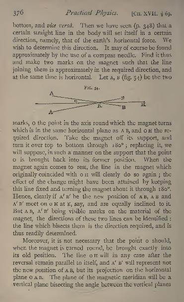
Practical Physics. [CH. XVII. 69.
bottom, and vice versa. Then we have seen (p. 348) that a
certain straight line in the body will set itself in a certain
direction, namely, that of the earth's horizontal force. Wewish to determine this direction. It may of course be found
approximately by the use of a compass needle. Find it thus
and make two marks on the magnet such that the line
joining them is approximately in the required direction, and
at the same time is horizontal. Let A, B(fig. 54) be the two
FIG. 54.
marks, o the point in the axis round which the magnet turns
which is in the same horizontal plane as A B, and o H the re-
quired direction. Take the magnet off its support, and
turn it over top to bottom through 180; replacing it, we
will suppose, in such a manner on the support that the pointo is brought back into its former position. When the
magnet again comes to rest, the line in the magnet which
originally coincided with o H will clearly do so again ;the
effect of the change might have been attained by keepingthis line fixed and turning the magnet about it through 180.
Hence, clearly if A' B' be the new position of A B, A B and
A' B' meet on o H at K, say, and are equally inclined to it.
But A B, A' B' being visible marks on the material of the
magnet, the directions of these two lines can be identified :
the line which bisects them is the direction required, and is
thus readily determined.
Moreover, it is not necessary that the point o should,
when the magnet is turned round, be brought exactly into
its old position. The line o H will in any case after the
reversal remain parallel to itself, and A' B' will represent not
the new position of A B, but its projection on the horizontal
plane o A B. The plane of the magnetic meridian will be a
vertical plane bisecting the angle between the vertical planes
CH. XVII. 69.] Magnetism. 377
through the old and new positions of any line A B fixed in
the magnet. The experiment then in its simplest form maybe performed as follows :
Fasten a sheet of white paper down on to the table, and
suspend over it a magnet of any shape whatever, hanging
freely in a stirrup, as already described, by a fibre which
has been carefully freed from torsion (p. 368). The magnetshould be as close down to the paper as is possible.
Make two marks on the magnet, one at each end, and
looking vertically down on it, make two dots on the paper
with a fine- pointed pencil, or some other point, exactly
under the two marks ; join these two dots by a straight line.
Reverse the magnet in its stirrup, turning the top to the
bottom, and let it again come to rest. Make two dots as
before on the paper vertically below the new positions of the
marks, and join these two. The line bisecting the angle
between the two lines thus drawn on the paper gives the
direction of the horizontal component of the earth's force.
In performing the experiment thus, serious error is intro-
duced if the observer's eye be not held vertically over the
magnet in each case. This is best ensured by placing a
piece of plane mirror on the table below the magnet, leaving
the part of the paper which is just below the mark un;
covered, and placing the eye at some distance away, and in
such a position that the image of the magnet, formed byreflectidn in the mirror, is exactly covered by the magnetitself
;then if the dot be made on the paper in such a
manner as to appear to the observer to be covered by the
mark on the magnet, it is vertically below that mark.
If the position of true geographical north at the place
of observation be known, we can obtain the angle between
the true north and the magnetic north from this experiment.
This angle is known as the magnetic declination.
The declinometer, or apparatus used to measure the
declination, is constructed on exactly the same principles
as those made use of in the foregoing experiment, more
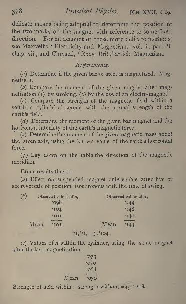
378 Practical Physics. [CH. XVII. 69.
delicate means being adopted to determine the position of
the two marks on the magnet with reference to some fixed
direction. For an account of these more delicate methods,see Maxwell's *
Electricity and Magnetism,' vol. ii. part iii.
chap, vii., and Chrystal,*
Ency. Brit.,' article Magnetism.
Experiments.
(a} Determine if the given bar of steel is magnetised. Mag-netise it.
(b) Compare the moment of the given magnet after mag-netisation (i) by stroking, (2) by the use of an electro-magnet.
(c) Compare the strength of the magnetic field within a
soft-iron cylindrical screen with the normal strength of the
earth's field.
(d) Determine the moment of the given bar magnet and the
horizontal intensity of the earth's magnetic force.
(e) Determine the moment of the given magnetic mass about
the given axis, using the known value of the earth's horizontal
force.
(/) Lay down on the table the direction of the magneticmeridian.
Enter results thus :
(a) Effect on suspended magnet only visible after five or
six reversals of position, isochronous with the time of swing.
(y) Observed values of n^ Observed values of a
098 -144
104 -148
ioi -140
Mean 'ioi Mean -144
MjM^ 5I/IQ4.
(c) Values of n within the cylinder, using the same magnetafter the last magnetisation.
073
070068
M.ean '070
Strength of field within : strength without = 49 : 208.
Cn. XVII. 69.] Magnetism. 379
(ii] Using the last observations in(ft)
^ = 144
K (calculated from dimensions) = 379-9 gm.(cm.)*r = 40 cm.= 4 30'
Whence H = 'i76 C.G.S. units
M = 445-5 C.G.S. units.
(e) A sphere of radius 2-5 cm. experimented with.
Mass 500 gm.K = 1250 gm.(cm.)
2
H = -i;6 C.G.S. units
n = '0273
M = 52'4 C.G.S. units.
(/) Shew on a sheet of paper lines drawn parallel to the
edge of the table and to the direction of the horizontal com-
ponent of the earth's magnetic force respectively.
70. Exploration of the Magnetic Field due to a given
Magnetic Distribution.
Place a bar magnet on a large sheet of paper on a table.
In the neighbourhood of the magnet there will be a field
of magnetic force due to the joint action of the earth and
the bar magnet, and if a small compass needle be placedwith its centre at any point of the field, the direction of
the needle, when in equilibrium, will indicate, very approxi-
mately indeed, the direction of the line of magnetic force
which passes through its centre. Draw a line on the paperround the bar magnet at a distance of 2 or 3 cm. from it,
and mark off points along this line at intervals of 2 cm.
Take a small compass needle and lay it so that its centre
is above the first of the points so marked ; it will then set
itself in the direction tangential to the line of force which
passes through the point. Make marks on the paper
exactly opposite to the points at which the ends of the
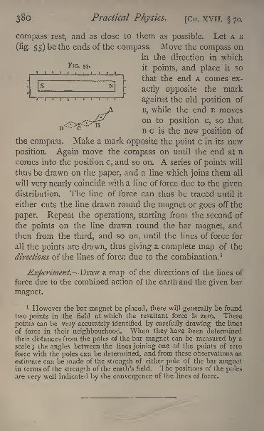
380 Practical Physics. [CH. XVII. 70.
compass rest, and as close to them as possible. Let A B
(% 55) be the ends of the compass. Move the compass on
in the direction in whichFlG - 5S *
it points, and place it so
that the end A comes ex-
actly opposite the mark
against the old position of
.A B, while the end B moves
.-.--..-.-'";'v^ n to position c, so that
B c is the new position of
the compass. Make a mark opposite the point c in its new
position. Again move the compass on until the end at B
comes into the position c, and so on. A series of points will
thus be drawn on the paper, and a line which joins them all
will very nearly coincide with a line of force due to the givendistribution. The line of force can thus be traced until it
either cuts the line drawn round the magnet or goes off the
paper. Repeat the operations, starting from the second of
the points on the line drawn round the bar magnet, and
then from the third, and so on, until the lines of force for
all the points are drawn, thus giving a complete map of the
directions of the lines of force due to the combination. ]
Experiment. Draw a map of the directions of the lines of
force due to the combined action of the earth and the given bar
magnet.
1 However the bar magnet be placed, there will generally be foundtwo points in the field at which the resultant force is zero. These
points can be very accurately identified by carefully drawing the lines
of force in their neighbourhood. When they have been determinedtheir distances from the poles of the bar magnet can be measured by a
scale ; the angles between the lines joining one of the points of zero
force with the poles can be determined, and from these observations an
estimate can be made of the strength of either pole of the bar magnetin terms of the strength of the earth's field. The positions of the polesare very well indicated by the convergence of the lines of force.
CH. xviii.] Electricity. 381
CHAPTER XVIII.
ELECTRICITY DEFINITIONS AND EXPLANATIONS OF
ELECTRICAL TERMS.
IN the last chapter we explained various terms relating
to magnetism. Just as in the neighbourhood of a magnetwe have a field of magnetic force, so, too, in the neighbour-
hood of an electrified body there is a field of electric force.
We proceed to consider certain facts, and to explain some
of the terms connected with the theory of electricity, a clear
comprehension of which will be necessary in order to
understand rightly the experiments which follow.
Most bodies can by friction, chemical action, or byvarious other means, be made to exert forces on other bodies
which have been similarly treated. The phenomena in ques-
tion are classed together as electrical, and the bodies are said
to have been electrified. By experiments with Faraday's ice-
pail among others (vide Maxwell's '
Elementary Electricity,'
p. 1 6, &c.), it has been shewn that these effects can be ac-
counted for by supposing the bodies to be charged with
certain quantities of one of two opposite kinds of electricity,
called respectively positive and negative, and such that equal
quantities of positive and negative electricity completelyannihilate each other.
An electrified body exerts force on other electrified
bodies in its neighbourhood in other words, produces a
field of electrical force and the force at any point dependson the position of the point, on the form and dimensions
of the electrified body, and on the quantity of electricity onthe body. By doubling the charge we can double the force.
We are thus led to look upon electricity as a quantity whichcan be measured in terms of a unit of its own kind, and we
may speak of the quantity of electricity on a body, in some-what the same way as we use the term quantity of magnetismfor the strength of a magnetic pole. The magnetic forces
382 Practical Physics. [CH. XVIII.
produced by a magnetic pole are due to a quantity of mag-netism concentrated at the pole. The electrical forces
produced by an .electrified body are due to a quantity of
electricity distributed over the body. By supposing the bodyto become very small while the quantity of electricity on
it still remains finite, we may form the idea of an electrified
point or a point charged with a given quantity of electricity.
With regard to the transmission of electrical properties
bodies may be divided into two classes, called respectively
conductors and non-conductors. To the latter the name'
dielectric'
is also applied.
DEFINITIONS OF CONDUCTORS AND NON-CONDUCTORS.
If a quantity of electricity be communicated to a conductor
or conducting body at one point, it distributes itself accord-
ing to certain laws over the body ; if, on the other hand, it
be communicated to a non-conductor, it remains concentrated
at the point where it was first placed. Quantities of electri-
city pass freely through the substance of a conductor; they
cannot do so through a non-conductor.
Quantities of electricity are of two kinds, having opposite
properties, and are called positive and negative respectively.
Two bodies each charged with the same kind of electricity
repel each other;two bodies charged with opposite kinds
attract each other. To move an electrified body in the field of
force due to an electrified system, against the forces of the sys-
tem requires work to be done, depending partly on the forces
of the system and partly on the quantity of electricity on the
body moved. We shall see shortly how best to define the
unit in terms of which to measure that quantity. Moreover,
owing to the action between the electrified body and the
rest of the system, alterations will generally be produced in
the forces in consequence of the motion.
DEFINITION OF RESULTANT ELECTRICAL FORCE. The
resultant electrical force at a point is the force which would
be exerted on a very small body charged with unit quantity
of positive electricity placed at the point, it being supposed
CH. XVIII.] Electricity. 383
that the presence of the body does not disturb the electrifi-
cation of the rest of the system.
Hence if R be the resultant electrical force at a point,
and e the number of units of electricity at that point, the
force acting on the body thus charged is R e.
If the body so charged be moved by the forces acting on
it, work is done.
DEFINITION OF ELECTROMOTIVE FORCE. The work
done in moving a unit quantity of positive electricity from
one point to another is called the electromotive force
between those points.
Hence, if the electromotive force (denoted by the
symbols E.M.F.), between two points be E, the work done in
moving a quantity e of positive electricity from the one
point to the other is E e. Electromotive force is sometimes
defined as the force which tends to move electricity ;the
definition is misleading. The name itself is perhaps ambi-
guous, for the electromotive force between two points is not
force, but work done in moving a unit of positive electricity;
it, therefore, has the dimensions of work divided by electrical
quantity (see p. 20). The term electromotive force at a
point, however, is sometimes used as equivalent to the re-
sultant electrical force. We shall avoid the term.
Suppose that a single body charged with positive
electricityis being considered, then it is found that the
force which this body exerts on any electrified body de-
creases very rapidly as the distance between the two bodies
is increased, becoming practically insensible when the
distance is considerable. We may define as the field of
action of an electrified system of bodies that portion of
space throughout which the electrical force which arises
from the action of those bodies has a sensible value. If a
quantity of positive electricity be moved from any point of
the field to its boundary by the action of the electrical
forces, work is done.
DEFINITION OF ELECTRICAL POTENTIAL. The electrical
potential at a point is the work which would be done by the
384 Practical Physics. [CH. XVIII
electrical forces of the system in moving a unit quantityof positive electricity from the point to the boundary of
the field, supposing this could be done without disturbing the
electrification of the rest of the bodies in the field.
We may put this in other words, and say that the
electrical potential at a point is the E.M.F. between that
point and the boundary of the field.
It is clear from this definition that the potential at all
points of the boundary is zero.
The work done by the forces of the system, in moving a
quantity e of positive electricity from a point at potential v
to the boundary, is clearly v e, and the work done in movingthe same quantity from a point at potential v
xto one at
potential v2 is e(v lv 2 ).
Hence, it is clear that the E.M.F. between two points is
the difference of the potentials of the points.
We are thus led to look upon the electric field as
divided up by a series of surfaces, over each of which the
potential is constant. The work done in moving a unit of
positive electricity from any point on one of these to any
point on another is the same.
When two points are at different potentials there is a
tendency for positive electricity to flow from the point at
the higher to that at the lower potential. If the two points
be connected by a conductor, such a flow will take place,
and unless a difference of potential is maintained between
the two points by some external means, the potential will
become equal over the conductor;for if one part of the
conductor be at a higher potential than another, positive
electricity immediately flows from that part to the other,
decreasing the potential of the one and increasing that of
the other until the two become equalised.
Now the earth is a conductor, and all points, not too
for apart,1 which are in metallic connection with the earth
are at the same potential.
1 If the points are far apart, electro-magnetic effects are produced
by the action of terrestrial magnetism.
CH. XVIII.] Electricity. 385
It is found convenient in practice to consider this,
the potential of the earth, as the zero of potential ;so that
on this assumption we should define the potential at a
point as the work done in moving a unit of positive elec-
tricity from that point to the earth. If the work done in
moving a unit of positive electricity from the earth to the
boundary of the field be zero, the two definitions are
identical;
if this be not the case, the potential at any point
measured in accordance with this second definition will
be less than its value measured in accordance with the first
definition by the work done in moving the unit of positive
electricity from the earth to the boundary of the field; but
since electrical phenomena depend on difference of potential,
it is of no consequence what point of reference we assume
as the zero of potential, provided that we do not change it
during the measurements. In either case the E.M. F. between
two points will be the difference of their potentials. Potential
corresponds very closely to level or pressure in hydrostatics.
The measure of the level of the water in a dock will dependon the point from which we measure it, e.g. high water-
mark, or the level of the dock-sill below high water-mark;but the flow of water from the dock if the gates be openedwill depend not on the actual level, but on the difference
between the levels within and without the dock, and this
will be the same from whatever zero we measure the levels.
Various methods have been discovered for maintaining a
difference of potential between two points connected by a
conductor, and thus producing between those points a con-
tinuous flow of electricity ; the most usual are voltaic or
galvanic batteries.
For the present, then, let us suppose that two pointsA and B are connected with the poles of a battery, A and B
being points on a conductor, and let us further suppose that
the pole of the battery connected with A is at a higher
potential than that connected with B. The pole connected
with A is said to be the positive pole. A continuous transfer
c c
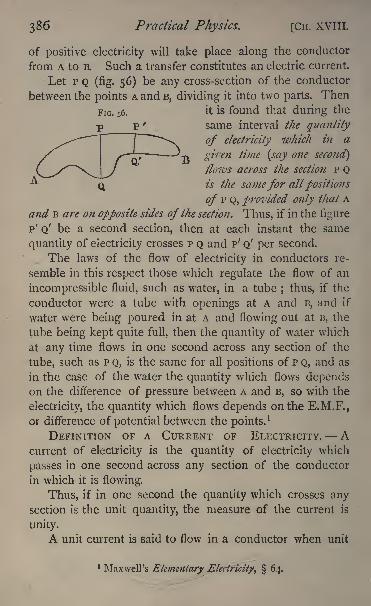
386 Practical Physics. [CH. XVIII.
of positive electricity will take place along the conductor
from A to B. Such a transfer constitutes an electric current.
Let P Q (fig. 56) be any cross-section of the conductor
between the points A and B, dividing it into two parts. Then
it is found that during the
same interval the quantity
of electricity which in a
given time (say one second]
flows across the section P Qis the samefor allpositions
of P Q, provided only that A
and B are on opposite sides of the section. Thus, if in the figure
p' Q' be a second section, then at each instant the same
quantity of electricity crosses P Q and P' Q' per second.
The laws of the flow of electricity in conductors re-
semble in this respect those which regulate the flow of an
incompressible fluid, such as water, in a tube ; thus, if the
conductor were a tube with openings at A and B, and if
water were being poured in at A and flowing out at B, the
tube being kept quite full, then the quantity of water which
at any time flows in one second across any section of the
tube, such as P Q, is the same for all positions of P Q, and as
in the case of the water the quantity which flows dependson the difference of pressure between A and B, so with the
electricity, the quantity which flows depends on the E.M.F.,
or difference of potential between the points.1
DEFINITION OF A CURRENT OF ELECTRICITY. Acurrent of electricity is the quantity of electricity which
passes in one second across any section of the conductor
in which it is flowing.
Thus, if in one second the quantity which crosses anysection is the unit quantity, the measure of the current is
unity.
A unit current is said to flow in a conductor when unit
1 Maxwell's Elementary glectficityt 64.
CH. XVITI.] Electricity. 387
quantity of electricity is transferred across any section in
one second.
But as yet we have no definition of the unit quantity of
electricity. To obtain this, we shall consider certain other
properties of an electric current.
A current flowing in a conductor is found to produce a
magnetic field in its neighbourhood. Magnetic force is
exerted by the current, and the pole of a magnet placed near
the conductor will be urged by a force definite in direction
and amount. If the conductor be in the form of a long
straight wire, a north magnetic pole would tend to movein a circle round the wire, and the direction of its motion
would be related to the direction of the current in the same
way as the direction of rotation is related to that of transla-
tion in a right-handed screw.
If instead of a magnetic pole we consider a compassneedle placed near the wire, the needle will tend to set
itself at right angles to the wire, and if we imagine a manto be swimming with the current and looking at the needle,
then the north end will be turned towards his left hand.
As to the intensity of the force, let us suppose that
the length of the wire is / centimetres, and that it is woundinto the form of an arc of a circle r centimetres in radius;
then when a current of intensity * circulates in the wire, it is
found that the magnetic force at the centre is proportional
to /i/r2 and acts in a direction at right angles to the plane
of the circle, and if * be measured in proper units, we maysay that the magnetic force is equal
* to / /" / r2.
If we call this F, we have
Let the length of the wire be one centimetre, and the
radius one centimetre, and let us inquire what must be the
strength of the current in order that the force on a unit
magnetic pole may be one dyne.2
1 See p. 394.2 See chap. ii. p. 18.
c c 2
388 Practical Physics. [CH. XVIII.
We have then in the equation
F= i, /= i, /= i,
and it becomes therefore
/= i;
that is, the strength of the current is unity, or the current
required is the unit current. Thus, in order that the
equation
may be true, it is necessary that the unit current should be
that current which circulating in a wire of unit length, bent
into the form of an arc of a circle of unit radius, exerts
unit force on a unit magnetic pole placed at the centre.
But we have seen already that the unit current is
obtained when unit quantity of electricity crosses any section
of the conductor. We have thus arrived at the definition of
unit quantity of electricity of which we were in search.
This definition is known as the definition of the electro-
magnetic unit of quantity.
DEFINITION OF C.G.S. ELECTRO-MAGNETIC UNIT QUAN-TITY AND UNIT CURRENT. Consider a wire one centimetre
in length bent into an arc of a circle one centimetre in radius.
Let such a quantity of electricity flow per second across anysection of this wire as would produce on a unit magnetic
pole placed at its centre a force of one dyne. This quantity
is the electro-magnetic unit of quantity of electricity, and
the current produced is the electro-magnetic unit of current.
With this definition understood then, we may say that if
a current of strength i traverse a wire of length / bent into
an arc of a circle of radius r, the force on a magnetic pole of
strength ;;/ placed at the centre of the circle will be mt//r2
dynes in a direction normal to the circle, and the strength
of the magnetic field at the centre is z'//>2
.
The magnetic field will extend throughout the neigh-
CH. XVIIL] Electricity. 389
bourhood of the wire, and the strength of this field at any
point can be calculated. Accordingly, a magnet placed in
the neighbourhood of the wire is affected by the current, and
disturbed from its normal position of equilibrium.
It is this last action which is made use of in galvano-
meters. Let the wire of length / be bent into the form of a
circle of radius r^ then we have
/ = 2 TT r,
and the strength of the field, at the centre of the. circle, is
2 TT i\r.
Moreover, we may treat the field as uniform for a
distance from the centre of the circle, which is small com-
pared with the radius of the circle. If then we have a
magnet of moment M, whose dimensions are small com-
pared with the radius of the circle, and if it be placed at the
centre of the circle so that its axis makes an angle with
the lines of force due to the circle, and therefore an angleof 90 - 6 with the plane of the circle, the moment of the
force on it which arises from the magnetic action of the
current is 2 TT u i sin 6 jr.
If, at the same time, < be the angle between the axis of
the magnet and the plane of the meridian, the moment of
the force due to the horizontal component H of the earth's
magnetic force is M H sin <;
if the small magnet be sup-
ported so as to be able to turn round a vertical axis, andbe in equilibrium under these forces, we must have the
equation
2 TT ui sin = M H sin <,
or
H r sin(ft p
2 TT sin'
if then we kno\v the value of if, and can observe the angles< and 0, and measure the distance r, the above equation
gives us the value of /.
39O Practical Physics. [CH. XVIII-
Two arrangements occur usually in practice. In the
first the plane of the coil is made to coincide with the mag-netic meridian
; the lines of force due to the coil are then at
right angles to those due to the earth, and
= 90-
<
Hencesin = cos
<f>,
and we have
._ H r tan(f>
2 TT
The instrument is then called a tangent galvanometer. In
the second the coil is turned round a vertical axis until the
axis of the magnet is in the position of equilibrium in the
same plane as the circle;the lines of force due to the coil
are then at right angles to the axis of the magnet, so that
the effect of the current is a maximum, and #=90. In
these circumstances, therefore, we have, if ^ be the deflection
of the magnet,
._ H r sin if
2 7T
The instrument is in this case called a sine-galvanometer.
We shall consider further on, the practical forms given
to these instruments. Our object at present is to get clear
ideas as to an electric current, and the means adopted to
measure its strength.
The current strength given by the above equation will,
using C.G.S. units of length, mass, and time, be given in
absolute units. Currents, which in these units are repre-
sented by even small numbers, are considerably greater
than is convenient for many experiments. For this reason,
among others, which will be more apparent further on, it is
found advisable to take as the practical unit of current, one-
tenth of the C.G.S. unit. This practical unit is called an
ampere.
H. XVIII.] Electricity. 391
DEFINITION OF AN AMPERE. A current of one ampereis one-tenth of the C.G.S. absolute unit of current.
Thus, a current expressed in C.G.S. units may be reduced
to amperes by multiplying by 10.
CHAPTER XIX.
EXPERIMENTS ON THE FUNDAMENTAL PROPERTIES OF
ELECTRIC CURRENTS MEASUREMENT OF ELECTRIC CUR-
RENT AND ELECTROMOTIVE FORCE.
71. Absolute Measure of the Current in a Wire,
THE wire in question is bent into the form of a circle,
which is placed approximately in the plane of the magneticmeridian. This is done by using a long magnet mounted
as a compass-needle and placing the plane of the wire by
eye parallel to the length of this magnet. The two ends
of the wire are brought as nearly into contact as is possible,
and then turned parallel to each other at right angles to the
plane of the circle; they are kept separate by means of a
small piece of ebonite, or other insulating material. Asmall magnet is fixed on to the back of a very light mirror,
and suspended, by a short single silk fibre, in a small metal
case with a glass face in front of the mirror, just as in a
Thomson's mirror galvanometer. The case is only just
large enough to allow the mirror to swing freely, so that the
air enclosed damps the vibrations rapidly. The case is
fixed to an upright stand and rests on levelling screws in
such a way that the centre of the magnet can be broughtinto the centre of the circle. A scale parallel to the planeof the circle is fixed some little distance in front of the
mirror, the level of the scale being very slightly above that
of the mirror. Below the scale is a slit, and behind that a
lamp, the light from which shines through the slit on to the
392 Practical Physics. [CH. XIX. 71.
mirror, and is reflected by it, throwing a bright spot of light
on to the scale, if the scale and lamp be properly adjusted.
The mirror is usually slightly concave, and by adjusting
the distance between the scale and the mirror, a distinct
image of the slit can be formed on the scale, and its position
accurately determined. In some cases it is convenient to
stretch a thin wire vertically across the middle of the slit,
and read the position of its image. If an image cannot be
obtained by simply varying the distance, through the mirror
not being concave, or from some other defect, a convex
lens of suitable focal length may be inserted between the
slit and the mirror; by adjusting the lens the image requiredcan be obtained. When there is no current passing throughthe wire the image should coincide with the division of the
scale which is vertically above the slit. To determine whether
or not the scale is parallel to the mirror, mark two points
on the scale near the two ends, and equidistant from the
middle point, and measure with a piece of string the dis-
tances between each of these two points and a point on the
glass face of the mirror case exactly opposite the centre
of the mirror. If these two distances be the same, the
scale is rightly adjusted ;if they be not, turn the scale,
still keeping the image of the slit vertically above the slit,
until they become equal. Then it is clear that the scale
is at right angles to the line which joins its middle point
to the mirror, and that this line is also at right angles
to the mirror. The scale, therefore, is parallel to the
mirror. If now the ends of the wire be connected with the
poles of a Daniell's battery, or with some other apparatuswhich maintains a difference of potential between them, a
current will flow in the wire. The magnet and mirror will
be deflected, and the spot of light will move along the scale,
coming to rest after a short time in a different position.
Note this position, and suppose the distance between it and
the original resting-point to be x\ scale divisions it will
be convenient when possible to use a scale divided into
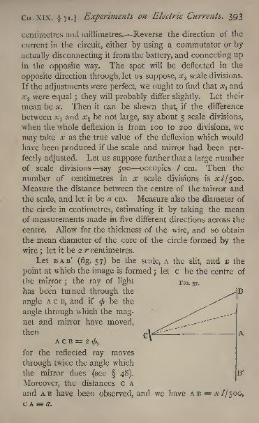
Cn.xix. 71.] Experiments on Electric Currents. 393
centimetres and millimetres. Reverse the direction of the
current in the circuit, either by using a commutator or by
actually disconnecting it from the battery, and connecting upin the opposite way. The spot will be deflected in the
opposite direction through, let us suppose, #2 scale divisions.
If the adjustments were perfect, we ought to find that x l and
x2 were equal ; they will probably differ slightly. Let their
mean be x. Then it can be shewn that, if the difference
between x}and x 2 be not large, say about 5 scale divisions,
when the whole deflexion is from 100 to 200 divisions, we
may take x as the true value of the deflexion which would
have been produced if the scale and mirror had been per-
fectly adjusted. Let us suppose further that a large numberof scale divisions say 500 occupies / cm. Then the
number of centimetres in x scale divisions is a; 7/500.
Measure the distance between the centre of the mirror and
the scale, and let it be a cm. Measure also the diameter of
the circle in centimetres, estimating it by taking the meanof measurements made in five different directions across the
centre. Allow for the thickness of the wire, and so obtain
the mean diameter of the core of the circle formed by the
wire;
let it be 2 r centimetres.
Let BAB'(fig. 57) be the scale, A the slit, and B the
point at which the image is formedj
let c be the centre of
the mirror;
the ray of light F IG> 57 .
has been turned through the
angle A c B, and if<j>
be the
angle through which the mag-net and mirror have moved,then
A c B = 2 <,
for the reflected ray moves
through twice the angle which
the mirror does (see 48). B'
Moreover, the distances c A
and AB have been observed, and we have A B = x //SOG,
c A = a.
394 Practical Physics. [CH. XIX. 71.
Thus
^ X I=A^=tan 2 <.500 a CA
From this equation then 2 < can be found, using a table
of tangents, and hence tan <, by a second application of the
table.
But the circle was placed in the magnetic meridian,
parallel, therefore, to the magnet, and the force due to the
current is consequently at right angles to that due to the
earth. We have, therefore, from the last section, if i re-
present the current,/= HT- tan </27r.
We have shewn in 69 how H is to be found, and the
values of r and tan < have just been determined;
the
value of TT is, of course, 3*142, and H may be taken as '180.
Thus we can measure / in C.G.S. absolute units. To find i
in amperes we have to multiply the result by 10, since the
C.G.S. unit of current contains 10 amperes.The repetition of this experiment with circles of different
radii would serve to demonstrate the accuracy of the funda-
mental law of the action of an electric current on a magnet.The experiment may, by a slight modification, be arrangedwith the more direct object of verifying the law in the follow-
ing manner. Set up two coils concentrically, in the magnetic
meridian, with a needle at their common centre. Let the
one coil consist of a single turn of wire and the other of
two turns, and let the radius of the second be double that of
the first. Then on sending the same current through either
coil the deflexion of the needle will be found to be the
same ;the best way, however, of demonstrating the equality
is to connect the two coils together so that the same cur-
rent passes through both, but in opposite directions; the
effect on the needle for the two coils respectively being equal
and opposite, the needle will remain undeflected. We are
indebted to Professor Poynting, of Birmingham, for the
CH. XIX. 71.] Experiments on Electric Currents. 395
suggestion of this method of verifying the fundamental
electro-magnetic law.
It should be noticed that the formula for the deflexion
does not contain any factor which depends on the magnetismof the suspended needle; mother words, the deflexion of a
galvanometer is independent of the magnetic moment of
its needle. This fact may also be experimentally verified
by repeating the experiment with different needles and
noticing that the deflexion is always the same for the same
current.
Experiment. Determine the strength of the current from
the given battery when running through the given circle.
Enter results thus:
Observations for diameter, corrected for thickness of the
wire
32 cm. 32-1 cm. 3 1-9 cm. 32 cm, 32*1 cm.
Mean value of r, i6'oi cm.
x^ 165 divisions of scale.
/ = space occupied by 500 divisions = 317 cm.2 = 607 cm.
tan 20 = -1723 tan = -0816.
^'=0342 C.G.S. unit = '342 ampere.
GALVANOMETERS.
The galvanometer already described, as used in the
last section, was supposed to consist of a single turn of
wire, bent into the form of a circle, with a small magnethanging at the centre. If, however, we have two turns of
wire round the magnet, and the same current circulates
through the two, the force on the magnet is doubled, for
each circle producing the same effect, the effect of the twois double that of one
;and if the wire have n turns, the
force will be n times that due to a wire with one turn.
Thus the force which is produced by a current of strength
396 PTactical Physics. [CH. XIX.
/, at the centre of a coil of radius r, having n turns of wire,
is 2 n TTt'/r.
But we cannot have n circles each of the same radius,
having the same centre;
either the radii of the different
circles are different, or they have different centres, or both
these variations from the theoretical form may occur. In
galvanometers ordinarily in use, a groove whose section is
usually rectangular is cut on the edge of a disc of woodor brass, and the wire wound in the groove.
The wire is covered with silk or other insulating material,
and the breadth of the groove parallel to the axis of the
disc is such that an exact number of whole turns of the wire
lie evenly side by side in it.
The centre of the magnet is placed in the axis of the
disc symmetrically with reference to the planes which boundthe groove. Several layers of wire are wound on, one above
the other, in the groove. We shall call the thickness of a
coil, measured from the bottom of the groove outwards
along a radius, its depth.
Let us suppose that there are n turns in the galvano-
meter coil. The mean radius of the coil is one n th of the
radius of a circle, whose circumference is the sum of the
circumferences of all the actual circles formed by the wire ;
and if the circles are evenly distributed, so that there are
the same number of turns in each layer, we can find the
mean radius by taking the mean between the radius of the
groove in which the wire is wound and the external radius
of the last layer. Let this mean radius be r;and suppose,
moreover, that the dimensions of the groove are so small
that we can neglect the squares of the ratios of the depth
or breadth of the groove to the mean radius r, then it can
be shewn * that the magnetic force, due to a current / in
the actual coil, is n times that due to the same current in
a single circular wire of radius r, so that it is equal to
2 11 7T ///
1
Maxwell, Electricity and Magnetism, vol. ii. 711.
CH. XIX.] Experiments on Electric Currents. 397
And if the magnet be also small compared with r, and
the plane of the coils coincide with the meridian, the re-
lation between the current / and the deflection < is given by
/ H r tan<f> / (2 n TT).
Unless, however, the breadth and depth of the coil be
small compared with its radius, there is no such simpleconnection as the above between the dimensions of the coil
and the strength of the magnetic field produced at its centre.
The strength of field can be calculated from the dimen-
sions, but the calculation is complicated, and the measure-
ments on which it depends are difficult to make with
accuracy.
DEFINITION OF GALVANOMETER CONSTANT. The
strength at the centre of a coil of the magnetic field pro-
duced by a unit current flowing in it, is called the galvano-meter constant of the coil.
Hence, if a current / be flowing in a coil of which the
galvanometer constant is G, the strength of the field at the
centre of the coil is G /, and the lines of force are at right
angles to the coil.
Let us suppose that a coil, of which the galvanometerconstant is G, is placed in the magnetic meridian, with a
magnet at its centre, and that the dimensions of the magnetare so small that, throughout the space it occupies, we maytreat the magnetic field as uniform
; then, if the magnet be
deflected from the magnetic meridian, through an angle </>
by a current t, the moment of the force on it due to the coil
is G / M cos<j>,M being the magnetic moment of the magnet,
while the moment of the force, due to the earth,is H M sin <;and since these must be equal, the magnet being in equili-
brium, we have/= H tan </G.
In using a tangent galvanometer it is not necessary that
the earth's directing force alone should be that which
retains the magnet in its position of equilibrium when no
Practical Physics. [CH. XIX.
current passes round the coil. All that is necessary is that
the field of force in which the magnet hangs should be
uniform, and that the lines of force should be parallel to
the coils. This may be approximately realised by a suitable
distribution of permanent magnets.If the coil of wire can be turned round a vertical axis
through its centre, parallel to the plane of the circles, the
instrument can be used as a sine galvanometer. For this
purpose place the coils so that the axis of the magnet lies
in their plane before the current is allowed to pass. Whenthe current is flowing, turn the coils in the same direction as
the magnet has been turned until the axis of the magnet again
comes into the plane of the coils, and observe the angle i//
through which they have been turned. Then we can shew,
as in chap, xviii., that
/= H sinJ/T/G.
To obtain these formulas, we have supposed that the
dimensions of the magnet are small compared with those of
the coil. If this be not the case, the moment of the force
produced by the magnetic action of the coil when used as
a tangent galvanometer is not MGCOS<, as above, but in-
volves other terms depending on the dimensions of, anddistribution of magnetism in, the magnet.
In order to measure the deflexions, two methods are
commonly in use. In the first arrangement there is attached
to the magnet, which is very small, a long pointer of glass,
aluminium, or some other light material. This pointer is
rigidly connected with the magnet, either parallel to or at
right angles to its axis, and the two, the magnet and
pointer, turn on a sharp-pointed pivot, being supported byit at their centre, or are suspended by a fine fibre free
from torsion. A circle, with its rim divided to degrees, or
in good instruments to fractions of a degree, is fixed in
a horizontal plane so that the axis of rotation of the
magnet passes through its centre, and the position of the
Cn. XIX.] Experiments on Electric Currents. 399
magnet is determined by reading the division of this circle
with which the end of the pointer coincides. In some
cases the end of the pointer moves just above the scale, in
others the pointer is in the same plane as the scale, the
central portion of the disc on which the graduations are
marked being cut away to leave space for it, and the gradua-tions carried to the extreme inner edge of the disc. With
the first arrangement it is best to have a piece of flat mirror
with its plane parallel to the scale, beneath the pointer, and,
when reading, to place the eye so that the pointer covers its
own image formed by reflexion in the mirror. The circle
is usually graduated, so that when the pointer reads zero, the
axis of the magnet is parallel to the plane of the coils if no
current is flowing.
In order to eliminate the effects of any small error in
the setting, we must proceed in the following manner :
Set the galvanometer so that the pointer reads zero,
pass the current through it, and let be the deflexion
observed. Reverse the direction of the current so that the
needle may be deflected in the other direction;
let the
deflexion be & If the adjustments were perfect the
current remaining the same we should have 0and 6' equal;in any case, the mean, ^(0+ 0'), will give a value for the
deflection corrected for the error of setting.
To obtain a correct result, however, the position of both
ends of the pointer on the scale must be read. Unless the
pointer is in all positions a diameter of the circle, that is,
unless the axis of rotation exactly coincides with the axis of
the circle, the values of the deflexions obtained from the
readings at the two ends will differ. If, however, we read the
deflexions 0, b say, of the two ends respectively, the mean
--(#+ #1), will give a value of the deflexion corrected for
errors of centering.1
Thus, to take a reading with a galvano-meter of this kind, we have to observe four values of the
deflexions, viz. two, right and left of the zero respectively,
1 See Godfray's Astronomy, 93.
4O Practical Physics. [CH. XIX.
for each end of the needle. This method of reading should
be adopted whether the instrument be used as a tangent or
a sine galvanometer.The second method of measuring the deflexion has been
explained at full length in the account of the last experiment
(p. 391). A mirror is attached to the magnet, and the motions
of the magnet observed by the reflexion by it of a spot of
light on to the scale. The following modification of this
method is sometimes useful.1 A scale is fixed facing the
mirror, (which should in this case be plane) and parallel to
it. A virtual image of this scale is formed by reflexion in
the mirror, and this image is viewed by a telescope which is
pointed towards the mirror from above or below the scale.
The telescope has cross-wires, and the measurements are
made by observing the division of the scale, which appearsto coincide with the vertical cross-wire, first without, and
then with a current flowing in the coil. For details of the
method of observation see 23.
In the best tangent galvanometers2 there are two coil?,
of the same size and containing the same number of turns,
placed with their planes parallel and their centres on the
same axis. The distance between the centres of the coils is
equal to the radius of either, and the magnet is placed with
its centre on the axis midway between the two coils. It has
been shewn 3 that with this arrangement the field of force
near the point at which the magnet hangs is more nearly
uniform than at the centre of a single coil. It has also
been proved that in this case, if G be the galvanometer con-
stant, n the number of turns in the two coils, r the mean
radius, and the depth of the groove filled by the wire, then
G 7~~
(J ~ A 75 )
5\/5 r \ r J
1 See 23, p. 146.2 Helmlioltz's arrangement, Maxwell, Electricity and Magnetism,
vol. ii. 715.3Maxwell, Electricity and Magnetism* vol. ii. 713.
CH. XIX.] Experiments on Electric Currents. 401
Various other forms of galvanometers have been devised
for special purposes. Among them we may refer to those
which are adapted to the measurement of the large currents
required for the electric light. An account of Sir William
Thomson's graded galvanometers arranged for this purposewill be found in
'
Nature,' vol. xxvi. p. 506, while the latest
forms of the instruments designed by Professors Ayrtonand Perry are described in the '
Philosophical Magazine'
for
April 1884.
On the Reduction Factor of a Galvanometer.
The deflexion produced in a galvanometer needle by a
given current depends on the ratio H/G, H being the strength
of the field in which the needle hangs when undisturbed,
and G the strength of the field due to a unit current in the
coil. This ratio is known as the reduction factor of the
galvanometer. Let us denote it by k, then
k=. H/G;
and if the instrument be used as a tangent galvanometer we
have/= k tan
;
if it be used as a sine galvanometer
i=.k sin/r,
< and\j/ being the deflexions produced in either case by a
current /.
It must be remembered that the reduction factor
depends on the strength of the magnetic field in which the
magnet hangs as well as on the galvanometer constant.
There is generally attached to a reflecting galvanometer a
controlling magnet capable of adjustment. The value of
k will accordingly depend on the position of this control
magnet, which in most instruments is a bar, arranged to
slide up and down a vertical axis above the centre of the
coils, as well as to rotate about that axis. The sensitiveness
4-O2 Practical Physics. [Cn. XIX,
of the instrument can be varied by varying the position of
this magnet,
On the Sensitiveness of a Galvanometer.
The sensitiveness of a galvanometer will depend on the
couple which tends to bring the needle back to its position
of equilibrium, and is increased by making that couplesmall. The couple is proportional to the magnetic momentof the needle and to the strength of the field in which
the magnet hangs. Two methods are employed to diminish
its value.
If the first method be adopted two needles are em-
ployed. They are mounted, parallel to each other, a short
distance apart, so that they can rotate together as a rigid
system about their common axis. Their north poles are in
opposite directions, and their magnetic moments are madeto be as nearly equal as possible. If the magnetic momentsof the two be exactly the same, and the magnetic axes in
exactly opposite directions, such a combination when placedin a uniform magnetic field will have no tendency to take
up a definite position. In practice this condition of absolute
equality is hardly ever realised, and the combination, if free
to move, will be urged to a position of equilibrium by a force
which will be very small compared with that which would
compel either magnet separately to point north and south.
It will take, therefore, a smaller force to disturb the com-
bination from that position than would be required for either
magnet singly. Such a combination is said to be astatic.
When used for a galvanometer the coils are made to
surround one needle only; the other is placed outside them,
either above or below as the case may be.
The magnetic action of the current affects mainly the
enclosed magnet ;the force on this is the same as if the
other magnet were not present, and hence, since the con-
trolling force is much less, the deflexion produced by a
given current is much greater. This deflexion is still further
CH. XIX.] Experiments on Electric Currents. 403
increased by the slight magnetic action between the current
and the second magnet.In some cases this second magnet is also surrounded by
a coil, in which the current is made to flow in a direction
opposite to that in the first coil, and the deflexion is therebystill further augmented.
In the second method the strength of the field in
which the needle hangs is reduced by the help of other
magnets ;if this method be adopted, the advantages of an
astatic combination may be partly realised with an ordinary
galvanometer by the use of control magnets placed so as to
produce a field of force opposite and nearly equal to that
of the earth at the point where the galvanometer needle
hangs. The magnetic force tending to bring the needle
back to its equilibrium position can thus be made as small
as we please neglecting for the moment the effect of the
torsion of the fibre which carries the mirror and the de-
flexion produced by a given current will be correspondinglyincreased.
The increase in sensitiveness is most easily determined,
as in 69, by observations of the time of swing, for if H
represent the strength of the field in which the magnet
hangs, we have seen( 69) that H=47r2
K/M T2,M being the
magnetic moment, K the moment of inertia, and T the time
of a complete period. But, being small, the deflexion pro-
duced by a given current, on which, of course, the sensitive-
ness depends, is inversely proportional to H;that is, it is
directly proportional to the square of T.
The method of securing sensitiveness thus by the use
of a control magnet is open to the objection that the small
variations in the direction and intensity of the earth's mag-netic force, which are continually occurring, become very
appreciable when compared with the whole strength of the
field in which the magnet hangs. The sensitiveness, and,
at the same time, the equilibrium position of the magnet,
are, therefore, continually changing.
DD 2
404 Practical P/iystcs. [CH. XIX.
On the Adjustment of a Reflecting Galvanometer.
In adjusting a reflecting galvanometer, we have first to
place it so that the magnet and mirror may swing quite
freely. This can be attained by the adjustment of the
levelling screws on which the instrument rests. There is
generally a small aperture left in the centre of the coils
opposite to that through which the light is admitted to the
mirror. This is closed by a short cylinder of brass or
copper which can be withdrawn, and by looking in from
behind, it is easy to see if the mirror hangs in the centre
of the coils as it should do.
The lamp and scale are now placed in front of the
mirror, the plane of the scale being approximately parallel
to the coils, and the slit through which the light comes
rather below the level of the mirror.
The magnet and mirror are adjusted, by the aid of the
control magnet, until the light is reflected towards the
scale. The position of the reflected beam can easily be
found by holding a sheet of paper close to the mirror so as
to receive it, moving the paper about without intercepting
the incident beam. By moving the control magnet, and
raising or lowering the scale as may be required, the spot
may be made to fall on the scale.
The distance between the galvanometer and scale must
now be varied until the image formed on the scale is as
clear and distinct as possible ; and, finally, the control
magnet must be adjusted to bring the spot to the central
part of the scale, and to give the required degree of sensi-
tiveness.
As we have seen, the sensitiveness will largely dependon the position of the control magnet. Its magnetic mo*ment should be such that when it is at the top of the bar
which supports it, as far, that is. as is possible from the
needle, the field which it alone would produce at the needle
should be rather weaker than that due to the earth. If this
CH. XIX. 72.] Experiments on Electric Currents. 405
be the case, and the magnet be so directed that its field is
opposite to that of the earth, the sensitiveness is increased at
first by bringing the control magnet down nearer to the coils,
becoming infinite for the position in which the effect of the
control magnet just balances that of the earth, and then as
the control magnet is still further lowered the sensitiveness
is gradually decreased.
The deflexion observed when a reflecting galvanometeris being used is in most cases small, so that the value of
<f>
measured in circular measure will be a small fraction;and
if this fraction be so small that we may neglect <3
,we may
put sin < = $ = tan ^> (see p. 45) and we get / = /<.
With a sensitive galvanometer in which the coils are
close to the magnet the ratio of the length of the magnetto the diameter of the coil is considerable, and the galvano-meter constant is a function of the deflexion
;so that k J3
not constant for all deflexions in such an instrument, but
depends on the angle <. If, however, the deflexions em-
ployed be small we may without serious error use the
formula / = ><, and regard k as a constant.
72. Determination of the Reduction Factor of a
Galvanometer.
If the dimensions and number of turns of the galvano-meter and the value of H can be measured accuratelythe reduction factor can be calculated. We shall suppose,
however, that these data cannot be directly measured, and
turn to another property of an electric current for a means
of determining the reduction factor.
Let / be a current which produces a deflexion < in a
galvanometer of which the reduction factor is k; then if it
be used as a tangent instrument we have
/= k tan</>,
and therefore,k = //tan $.
406 Practical Physics. [CH. xix. 72.
If we can find by some other means the value of z,we
can determine k by observing the deflexion < which it
produces.
Now it has been found that when an electric current is
allowed to pass through certain chemical compounds which
are known as electrolytes, the passage of the current is
accompanied by chemical decomposition. The process is
called Electrolysis ;the substance is resolved into two com-
ponents called Ions; these collect at the points at which
the current enters and leaves the electrolytes respectively.
The conductors by which the current enters or leaves the
electrolyte are known as the Electrodes 1
; that at which the
current enters the electrolyte is called the Anode, and the
component which appears there is the Anion. The conductor
by which the current leaves the electrolyte is the Kathode,
and the ion which is found there is the Kathion. An appa-ratus arranged for collecting and measuring the products of
electrolytic decomposition is called a Voltameter.
Moreover, it has been shewn by Faraday (' Exp. Res.'
ser. vii.) that the quantities of the ions deposited either at the
kathode or the anode are proportional to the quantity of
electricity which has passed. If this quantity be varied the
quantity of the ions deposited varies in the same ratio. This
is known as Faraday's law of electrolysis.
DEFINITION OF ELECTRO-CHEMICAL EQUIVALENT.The electro-chemical equivalent of a substance is the
number of grammes of the substance deposited by the pas-
sage of a unit quantity of electricity through an electrolyte
in which the substance occurs as an ion. Thus, if in a time
/ a current / deposits ;;/ grammes of a substance whose
electro-chemical equivalent is y, it follows from the above
definition, in conjunction with Faraday's law, that
m = y/V,1 The term 'electrode' was originally applied by Faraday in the
sense in which it is here used. Its application has now been extended,and it is employed in reference to any conductor by which electricityenters or leaves an electrical apparatus of any sort.
CH. XIX. 72.] Experiments on Electric Currents. 407
and hence
/= mlyt.
If, then, we observe the amount of a substance, of knownelectro-chemical equivalent, deposited in time /, we can find
the current, provided it has remained constant throughoutthe time /. If a current be allowed to pass between two
plates of copper immersed in a solution of sulphate of
copper, the sulphate is electrolysed and copper depositedon the kathode. The acid set free by the electrolysis
appears at the anode, and combines with the copper. The
quantity of copper deposited on the kathode in one second
by a unit current has been found to be -00328 gramme.This is the electro-chemical equivalent of copper. The loss
of weight of the anode is for various reasons found to be
somewhat in excess of this.
We proceed to describe how to use this experimentalresult to determine the reduction factor of a galvanometer.
Two copper plates are suspended in a beaker containinga solution of copper sulphate, by wires passing through a
piece of dry wood or other insulating material which forms
a covering to the beaker. The plates should be well cleaned
before immersion by washing them with nitric acid, andthen rinsing them with water, or by rubbing them with
emery cloth, and then rinsing them with water. They mustthen be ^thoroughly dried. One of the plates must be care-
fully weighed to a milligramme. On being put into the
solution this plate is connected to the negative pole the
zinc of a constant battery, preferably a Daniell's cell, bymeans of copper wire
; the other plate is connected with one
electrode of the galvanometer. The positive pole of the
battery is connected through a key with the other pole of
the galvanometer, so that on making contact with the keythe current flows from the copper of the battery round
the galvanometer, through the electrolytic cell, depositing
copper on the weighed plate, and finally passes to the zinc
or negative pole of the battery. Since the galvanometer
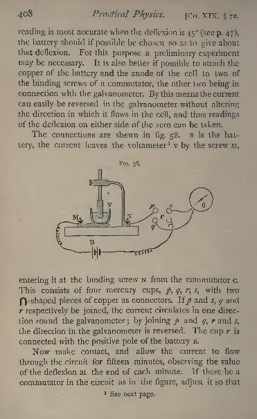
408 Practical Physics. [Cn. XIX. 72.
reading is most accurate when the deflexion is 45 (see p. 47),
the battery should if possible be chosen so as to give about
that deflexion. For this purpose a preliminary experiment
may be necessary. It is also better if possible to attach the
copper of the battery and the anode of the cell to two of
the binding screws of a commutator, the other two being in
connection with the galvanometer. By this means the current
can easily be reversed in the galvanometer without altering
the direction in which it flows in the cell, and thus readingsof the deflexion on either side of the zero can be taken.
The connections are shewn in fig. 58. B is the bat-
tery, the current leaves the voltameter 1 v by the screw M,
FIG. 58.
entering it at the binding screw N from the commutator c.
This consists of four mercury cups, /, q, r^ s, with two
p| -shaped pieces of copper as connectors, lip and s, q and
r respectively be joined, the current circulates in one direc-
tion round the galvanometer ; by joining / and q, r and sy
the direction in the galvanometer is reversed. The cup r is
connected with the positive pole of the battery B.
Now make contact, and allow the current to flow
through the circuit for fifteen minutes, observing the value
of the deflexion at the end of each minute. If there be a
commutator in the circuit as in the figure, adjust it so that
> See next page.
CH. XIX. 72.] Experiments on Electric Currents. 409
the current flows in opposite directions during the two
halves of the interval. Let</>be the mean of the deflexions
observed. If the battery has been quite constant the de-
flexions observed will not have varied from minute to
minute;in any case the deflexion must not have changed
much during the interval. If any great variation shews
itself, owing to changes in the battery or voltameter, the ex-
periment must be commenced afresh.
At the end of the fifteen minutes the weighed plate must
be taken out of the solution, washed carefully, first under
the tap, and then by pouring distilled water on it, and
finally dried by being held in a current of hot dry air. It
is then weighed carefully as before. It will be found to
have increased in weight; let the increase be m grammes.Then the increase per second is ;/(i5 x 60), and since the
electro-chemical equivalent of copper is -00328, the average
value of the current in C.G.S. units (electro-magnetic mea-
sure) is
w/(6ox 15 X -00328).
But if <p, 2 . . . ir,be the readings of the deflexion,
this average value of the current is also
TV^(tan0! + tan ^2+ tan0 15).
And if 0! 02, &c., are not greatly different, this expressionis very nearly equal to /dtan 0, where is the average value
of1?... 15 . We thus find
k =60 x 15 x -00328 x tan
If the factor is so small that the copper deposited in
fifteen minutes * grammes is too little to be determined
accurately, the experiment must be continued in the same
way for a longer period. It must be remembered that the
mass m is to be expressed in grammes.Instead of using a glass beaker to hold the sulphate,
it is sometimes convenient to make the containing vessel
Practical Physics. [Cn. XIX. 72.
itself one of the electrodes. Thus a copper crucible maybe used as cathode, like the platinum one in PoggendorfPsvoltameter
;in this the sulphate is placed, and the anode may
be a rod of copper which hangs down into it. This form is
shewn in the figure.
We have already said that if the dimensions of the galva-nometer coil, and the number of turns of the wire of which
it is composed can be determined, the value of k can be
calculated, provided that the value of H be known; or, on the
other hand, H can be found from a knowledge of the dimen-
sions, and of the value of k determined by experiment.For if G be the galvanometer constant, r the mean radius,
and n the number of turns, we h.ave
G = 2 -n-n/r.
Also
k H/G.Whence
H = G/ = 2 Trnkfr.
The current, which is determined by the observations
given above, is measured in C.G.S. units. The value of k
gives the current which deflects the needle 45, measured
also in the same units. To obtain the value in amperes wemust multiply the result by 10, since the C.G.S. unit of
current contains 10 amperes.
Experiment. Determine the reduction factor of the given
galvanometer by electrolysis, comparing your result with that
given by calculation.
Enter the results thus
Battery 3 Daniells
Gain of kathode .... -2814 gm.Deflexion, greatest .... 46
least .... 45 30'
mean of 15 . . 45 50'
Time during which experiment lasted 15 minutes
Value of k -0932 C.G.S. unit
Radius of wire , 16-2 cm.
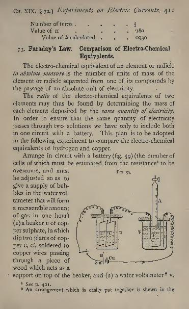
CH. XIX. 72.] Experiments on Electric Currents. 411
Number of turns .
Value of H . .
Value of k calculated
5
180
0930
73. Faraday's Law. Comparison of Electro-Chemical
Equivalents.
The electro-chemical equivalent of an element or radicle
in absolute measure is the number of units of mass of the
element or radicle separated from one of its compounds bythe passage of an absolute unit of electricity.
The ratio of the electro-chemical equivalents of two
elements may thus be found by determining the mass of
each element deposited by the same quantity of electricity.
In order to ensure that the same quantity of electricity
passes through two solutions we have only to include both
in one circuit with a battery. This plan is to be adoptedin the following experiment to compare the electro-chemical
equivalents of hydrogen and copper.
Arrange in circuit with a battery (fig. 59) (the number of
cells of which must be estimated from the resistance 1 to be
overcome, and must
be adjusted so as to
give a supply of bub-
bles in the water vol-
tameter that will form
a measurable amountof gas in one hour)
(i) a beaker u of cop-
per sulphate, in which
dip two plates of cop-
per c, c', soldered to
copper wires passing
through a piece of
wood which acts as a
support on top of the beaker, and (2) a water voltameter 2v.
1 See p. 421.2 An arrangement which is easily put together is shewn in the
FIG. 59.
412 Practical Physics. [Cn. XIX. 73.
Mount over the platinum plate p', by which the current is
to have the voltameter, a burette to be used for measuringthe amount of hydrogen generated during the experiment,
taking care that all the hydrogen must pass into the burette.
Place a key in the circuit, so that the battery may be thrown
in or out of circuit at will.
The zinc of the battery must be in connection with the
plate c' on which copper is to be deposited. The copper or
platinum is in connection with the platinum plate P, onwhich oxygen will be deposited.
About three Grove's cells will probably be required for
a supply of gas that can be measured in a convenient time;
and as this will correspond to a comparatively large current,
the plates of copper should be large, say 6 in. x 3 in., or the
deposit of copper will be flocculent and fall off the plate.
When the battery has been properly adjusted to give a
current of the right magnitude, the apparatus will be in a
condition for commencing the measurements. Accordingly,take out, dry, and carefully weigh the copper plate on
which the metal will be deposited during the experiment.This of course is the plate which is connected with the
negative pole of the battery. Let its weight be w.
After weighing the copper plate no current must be
sent through the voltameter containing it, except that one
which is to give the required measurement.
Read the position of the water in the burette the
height in centimetres of the water in the burette above
the level of the water in the voltameter. Let this be //,
Read the barometer;
let the height be H. Read also a
thermometer in the voltameter; let the temperature be t G,
Make the battery circuit by closing the key and allow the
figure. The plate P' is inside a porous pot, such as is used in a
Leclanche battery, and the open end of the burette is sealed into the
top of the pot by means of pitch or some kind of insulating cement.
The hydrogen is formed inside the pot and rises into the burette.
A graduated Hofmann voltameter is of course better, but the above canbe made in any laboratory with materials which are always at hand.
Cn. XIX. 73.] Experiments on Electric Currents. 413
current to pass until about twenty centimetres of the burette
have been filled by the rising gas. Shut off the current,
and dry and weigh the same plate of copper again ;let the
weight be w'.
Then the amount of copper deposited by the current is
w' w.
Read again the position of the water in the burette.
From the difference between this and the previous reading
we may obtain the volume of the gas generated. Let the
difference in volume actually observed be v cubic' centi-
metres, and let the height of the water in the burette
above that in the voltameter at the end of the experimentbe //'.
Before using v to find the mass of hydrogen deposited
we have to apply several corrections.
There was some gas above the water in the burette
before the experiment began. The pressure of the gas
above the water has been increased by the experiment, and
this gas has in consequence decreased in volume. Werequire to find what the decrease is.
Let the original volume of the gas be v. The gradua-tions on the burette are generally not carried to the end,
and to find v we require to know the volume between the
last graduation and the tap of the burette. For this purposea second * burette is needed. This is filled with water to a
known height. The burette to be used in the experimentis taken and inverted, being empty. Water is run into it
from the second burette until it is filled up to the first
graduation ;the quantity of water so run in is found by
observing how far the level in the second burette has fallen.
Or, if it be more convenient, the method may be reversed;
the. second burette being partly filled as before, the first
burette is also filled up to some known graduation, and
all the water which it contains is run out into the second ;
the rise in level in this gives the quantity of water which
has run out, and from this we can find the volume required
414 Practical Physics. [CH. XIX. 73.
between the bottom of the burette and the first graduation ;
knowing this we find the volume v easily.
Now this gas of volume v was at the commencementunder a pressure equal to the difference between the
atmospheric pressure and the pressure due to a column of
water of height h if 8 be the specific gravity of mercury,the pressure due to a column of water of height h is the
same as that due to a column of mercury of height ///8;
so that H being the height of the barometer, the pressureof the gas will be measured by the weight of a column of
mercury of height H ///8, while at the end of the experi-
ment the pressure is that due to a column H /*'/8.
Therefore the volume which the gas now occupies is
h
so that the decrease required is
h-ti
and h 1
being small compared with nS, we may write this:
This must be added in the observed volume v to find
the volume occupied by the gas electrolysed, at a pressure
due to a column of mercury of height nA'/S, giving us
thus as the volume,
It is sometimes more convenient to avoid the necessity
for this correction by filling the burette with water before
beginning, so that v9the space, initially filled with gas is
CH. XIX. 73.] Experiments on Electric Currents. 415
zero. If this plan be adopted we shall still require to knowthe volume between the end of the burette and the gradua-
tions, and this must be obtained as described above.
Correction for aqueous vapour. The solution of sul-
phuric acid used in the voltameter is exceedingly dilute,
and it may be supposed without error that the hydrogen gas
comes off saturated with aqueous vapour ;the pressure of
this vapour can be found from the table (34), for the tem-
perature of the observation, t C. Let it be e. Then if e be
expressed as due to a column of mercury of e centimetres in
height, the pressure of the hydrogen will be measured by
and its volume at this pressure and temperature / is
Thus its volume at a pressure due to 76 centimetres and
temperature o C. is
c.c.
Let this be v'. The weight required is v' x '0000896 gm.,
0000896 being the density of hydrogen.But according to Faraday's fundamental law of electro-
lysis, the weights of two elements deposited by the samecurrent in the same time are proportional to their chemical
equivalents. We must, therefore, have
r= chemical equivalent of copper.v' x "0000896
The value of the equivalent, as deduced from chemical
experiments, is 31*75.
Experiment. Determine by the use of voltameters the
chemical equivalent of copper.
41 6 Practical Physics. [CH. XIX. 73.
Enter results thus :
w =61-0760 gms. h =20 cm.
w' = 6 1 1 246 gms. h' = 5 cm.
v =18-5 c.c. e =1-9 cm.
v = 1-25 c.c. / =15 C.
H =75*95 cm. v' = 17-0 c.c.
Chemical equivalent= 31 -9
74. Joule's Law Measurement of Electromotive Force.
We have seen that work is done when a quantity of
electricity passes from a point at one potential to a second
point at a different one. If Q be the quantity of electricity
which passes thus, and E the difference of potential, or
electromotive force, maintained constant between the points
while Q passes, then the work done is Q x E. If the electricity
pass as a steady current of strength c, for a time / seconds,
then, since the strength of a current is measured by the
quantity which flows in a unit of time, we have Q= c/, and if
w be the work done,
w= E c t.
If this current flow in a wire the wire becomes heated, and
the amount of heat produced measures the work done,
for the work which the electricity does in passing from the
point at high to that at low potential is transformed into heat.
If H be the amount of heat produced and j the mechanical
equivalent of heat, that is, the number of units of work
which are equivalent to one unit of heat, then the work
required to produce H units of heat is j H. Hence we have
whenceE = JH/(C/).
Now j is a known constant, H can be measured
by immersing the wire in a calorimeter (see 39) and
noting the rise of temperature of a weighed quantity of
Cir. XIX. 74.] Experiments on Electric Currents. 417
water which is contained therein;
if a copper-voltameterbe included in the circuit c t is obtained, knowing the
electro-chemical equivalent of copper, by determining the
increase in weight of the cathode. We can thus find E,
the difference of potential between the two points at which
the current respectively enters and leaves the wire in the
calorimeter. For the calorimeter we use a small vessel of
thin sheet copper polished on the outside and suspended in
another copper vessel, as in 39. The water equivalentof this must be determined, as is explained in that section,
either experimentally or by calculation from the weightof the vessel and the known specific heat of copper, which
for this purpose may be taken as 'i. A small stirrer
made of thin copper wire coiled into a spiral may be
included in the estimate with the calorimeter determination.
The outer vessel of the calorimeter is closed by a copperlid with a hole in the middle, through which a cork passes.
The end of the stirrer passes through a hole in this cork,
and through two other holes pass two stout copper wires,
to the ends of which the wire to be experimented on is
soldered. The thermometer is inserted through a fourth
hole. The bulb of the thermometer should be small, and
the stem should be divided to read to tenths of a degree.The wire should be of German-silver covered with silk and
coiled into a spiral. Its length and thickness will dependon the nature of the source of electromotive force used.
If we take a battery of three Grove's cells of the usual
pint size, it will be found that the electrical resistance of
the wire (see chap, xx.) should be about 4 ohms. The two
ends are soldered on to the copper electrodes and the wire
completely immersed in the water of the calorimeter. It
must be carefully remembered that the quantity which weare to determine is the difference of potential between the
two points at which the wire cuts the surface of the water.
Some of the heat developed in the wire will of course
remain in it, and in our calculations we ought strictly to
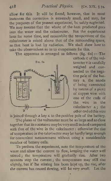
Practical Physics. [CH. XIX. 74,
allow for this. It will be found, however, that in most
instances the correction is extremely small, and may, for
the purposes of the present experiment, be safely neglected.
We may assume that the whole of the heat produced goes
into the water and the calorimeter. But the experiment
lasts for some time, and meanwhile the temperature of the
calorimeter is raised above that of the surrounding space,
so that heat is lost by radiation. We shall shew how to
take the observations so as to compensate for this.
The apparatus is arranged as follows(fig. 60) : The
cathode c of the vol-
FlG - 6o tameter v is carefully
weighed and con-
nected to the nega-
tive pole of the bat-
tery B, the anode
c' being connected
by means of a piece
of copper wire with
one of the ends of
the wire in the
calorimeter A;
the
other end ofthis wire
is joined through a key K to the positive pole of the battery.
The plates of the voltameter must be so large and so close
together that its resistance maybe very small indeed comparedwith that of the wire in the calorimeter : otherwise the rise
of temperature in the calorimeter may be hardly large enoughfor convenient measurement without using a considerable
number of battery cells.
To perform the experiment, note the temperature of the
water and allow the current to flow, keeping the water well
stirred ;the temperature will gradually rise. After two
minutes stop the current;the temperature may still rise
slightly, but if the stirring has been kept up, the rise, after
the current has ceased flowing, will be very small, Let the
Cn. XIX. 74.] Experiments on Electric Currents. 419
total rise observed be rt degrees. Keep the circuit broken
for two minutes;the temperature will probably fall. Let
the fall be r.2 degrees. This fall during the second two
minutes is due to loss of heat by radiation;and since
during the first two minutes the temperature did not differ
greatly from that during the second two, we may supposethat the loss during the first two minutes was approximatelythe same as that during the second two
;so that, but for this
loss, the rise of temperature during those first two minutes
would have been TJ -fr2 degrees.
We thus find the total rise of temperature produced in
the mass of water in two minutes by the given current by
adding together the rise of temperature during the first two
minutes and the fall during the second two minutes. Takesix observations of this kind, and let the total rise of tempera-ture calculated in the manner above described be T degrees ;
let the mass of water, allowing for the water equivalent of the
calorimeter and stirrer, be m grammes, then the quantity of
heat given out by the current in twelve minutes is m r units.
Let M grammes of copper be deposited by the samecurrent
;then since the passage of a unit of electricity
causes the deposition of -00328 gramme of copper, the
total quantity of electricity which has been transferred is
M/ -003 2 8 units, and this is equal to ct in the equation forE.
HenceE= j m T x '0032 8 /M.
Now the value of j inC.G.S. units is 42 x IO G,so that we
haveE= 42ox 328 xm XT/M.
The value of E thus obtained will be given in C.G.S. units;
the practical unit of E.M.F. is called a volt, and one volt con-
tains 10 8 C.G.S. units;hence the value of E in volts is
420 x 328 x m x T/(M x io8).
We have used the results of the experiment to find E. If,
however, E can be found by other means and we shall
E E 2
420 Practical Physics. [Cn. XIX. 74.
see shortly how this may be done the original equation,
JH= EC/, maybe used to find j or c. It was first employedby Joule for the former of the two purposes, i.e. to calculate
the mechanical equivalent of heat, and the law expressed
by the equation is known as Joule's law.
Experiment Determine the difference of potential betweenthe two ends of the given wire through which a current is
flowing.
Enter results thus :
Mass of water ..... 24-2 gms.Water equivalent of the calorimeter . 4-2 gms.
m .... 28-4 gms.M .... '222 gm.
Total rise of temperature for each two minutes :
4 4 '4 4'4 4'2 4 3'8r . . . 24 -8
E = 4-37 x I08 =4-37 voltS.
CHAPTER XX.
AND ELECTROMOTIVE FORCES.
WE have seen that if two points on a conductor be at
different potentials, a current of electricity flows through the
conductor. As yet we have said nothing about the relation
between the difference of potential and the current produced.This is expressed by Ohm's law, which states that the current
flowing between any two points of a conductor is directly
proportional to the difference of potential between those
points so long as the conductor joining them remains the
same and in the same physical state. Thus, if c be the
current, and E the electromotive force, c is proportional to
E, and we may write
CH. XX.] Ohm's Law. 421
where R is a quantity which is known as the resistance of
the conductor. It depends solely on the shape and tempera-ture of the conductor, and the nature of the material of
which it is composed, being constant so long as these re-
main unaltered.
DEFINITION OF ELECTRICAL RESISTANCE. It is found
by experiment that the ratio of the E.M.F. between two
points to the current it produces, depends only on the con-
ductor which connects the two points, and is called the
resistance of the conductor.
The reciprocal of the resistance that is, the ratio of the
current to the electromotive force is called the conductivity
of the conductor.
Thus between any two points on a conductor there is
a certain definite resistance : a metal wire, for example, has
an electrical resistance of so many units depending on its
length, cross-section, material, and temperature. Resistance
coils are made of such pieces of wire, covered with an
insulating material, cut so as to have a resistance of a
certain definite number of units and wound on a bobbin.
The ends of the coil are fastened in some cases to bind-
ing screws, in others to stout pieces of copper which, whenthe coil is in use, are made to dip into mercury cups,
through which connection is made with the rest of the
apparatus used. We refer to 78 for a description of the
method of employing such coils in electrical measurements.
Standards of resistance have the advantages of material
standards in general. The resistance is a definite property
of a piece of metal, just as its mass is. The coil can be
moved about from place to place without altering its
resistance, and so from mere convenience electrical resist-
ance has come to be looked upon as in some way the
fundamental quantity in connection with current electricity.
We have defined it by means of Ohm's law as the ratio of
electromotive force to the current. Whenever difference of
potential exists between two points of a conductor, a current
422 Practical Physics. [Cn. XX.
of electricity is set up, and the amount of that current de-
pends on the E.M.F. and the resistance between the points.
We may say that electrical resistance is that property of
a conductor which prevents a finite electromotive force from
doing more than a finite quantity of work in a finite time.
Were it not for the resistance, the potential would be instan-
taneously equalised throughout the conductor;
a finite
quantity of electricity would be transferred from the one
point to the other, and therefore a finite quantity of work
would be done instantaneously.
The work actually done in time / is, we have seen,
W = E C /,
and by means of the equation c = E/R expressing Ohm's
law, we may write this
W = C E / = E2
//R =. C2 R f.
Moreover the E.M.F. between two points is given if we
know the resistance between them and the current, for we
have E = c R.
On the Resistance of Conductors in Series and Multiple Arc.
If AB, EC be two conductors of resistances R! and R 2 ,
the resistance between A and c is Rj-fR 2 . For let the
potentials at A, B, c be v b v 2,v3 respectively, and suppose
that owing to the difference of potential a current i is
flowing through the conductors. This current is the same
in the two conductors (see p. 386), and if R be the resist-
ance between A and c, we have from Ohm's law
L>ut by adding the first two equations we have
Vi-v3=
(R, + R 2)/;.*. R=R 1 +R 2.
di. xx.j Ohm's Law. 423
By similar reasoning it may be shewn that the resultant
resistance of any number of conductors placed end to endis equal to the sum of the resistances of the several con-
ductors. Conductors connected in this manner are said to
be in series.
Again, let there be two conductors of resistances RJ, R 2 ,
joining the same two points A and B, and let R be the
equivalent resistance of the two, that is. the resistance of a
conductor, which, with the same E.M.F. would allow the
passage of a current of electricity equal to the sum of those
which actually flow in the two conductors. Hence, if vl5v2
be the potentials at A and B, we have
XiT v2-/ .Vi- v
2_, ." ~ll >
~--
and
Also
f"l*S *
Conductors joined up in the above manner are said to
be connected in multiple arc; thus, remembering that the
reciprocal of the resistance is called the conductivity, we
may shew by reasoning precisely similar to that given above
that the conductivity of a system of any number of con-
ductors in multiple arc is the sum of the conductivities
of the several conductors.
Let B A c be a circuit including a battery B, and supposethat we wish to send between the two points, A and c,
only i/th part of the current produced by the battery.
Let R be the resistance between A and c. Connect these
two points by a second conductor of resistance, R/( i).
424 Practical Physics. [Cn. XX.
Let /j be the current in the original conductor between
A and c, /2 tne current in the new conductor, i the current
in the rest of the circuit. Then we have
and
/=/! + z"2 ~m\So that
/!= */.
The second conductor, connected in this manner with
the two points, is called a shunt, and the original circuit
is said to be shunted.
Shunts are most often used in connection with galvano-
meters. Thus we might require to measure a current bythe use of a tangent galvanometer, and, on attempting to
make the measurement, might find that the galvanometerwas too sensitive, so that the deflexion produced by the cur-
rent was too large for measurement. By connecting the
electrodes of the galvanometer with a shunt of suitable
resistance we may arrange to have any desired fraction of
the current sent through the galvanometer.This fraction can be measured by the galvanometer, and
the whole current is obtained from a knowledge of the
resistances of the shunt and galvanometer. A galvanometeris often fitted with a set of shunts, having resistances 1/9,
1/99, and */999 of its own resistance, thus enabling -i, -01,
or -ooi of the whole current to be transmitted through it.
In applying Ohrn's law to a circuit in which there is a
battery of electromotive force E, it must be rememberedthat the battery itself has resistance, and this must be in-
cluded in the resistance of the circuit. Thus, if we have a
circuit including a resistance R, a battery of E.M.F. E andresistance B, and a galvanometer of resistance G, the total
resistance in the circuit is R+ B+ G, and the current is
CH. XX.] Ohm's Law. 425
The normal E.M.F. of the battery is taken to be the
difference of potential between its poles when they are
insulated from each other. If they be connected together,
the difference of potential between them will depend on
the resistance of the conductor joining them. In the case
in point this is R+ G; and since the difference of potential
is found by multiplying together the current and the resist-
ance, it will in that case be
E(R+G)/(R+G+ B).
On the Absolute Measurement of Electrical Resistance. .
Electrical resistance is measured in terms of its properunit defined by the equation
R=5.C
For let a conductor be such that unit difference of
potential between its two ends produces unit current ;then
in the above equation E and c are both unity ;so that R
is also unity and the conductor in question has unit re-
sistance.
DEFINITION OF AN ABSOLUTE UNIT RESISTANCE. Theunit of resistance is the resistance of a conductor in which
unit electromotive force produces unit current.
This is a definition of the absolute unit. Now it is found 1
that onk
the C.G.S. system of units the unit of resistance
thus defined is far too small to be convenient. There-
fore, just as was the case for E.M.F., a practical unit of
resistance is adopted, and this contains io 9 absolute C.G.S.
units, and is called an * ohm '
;so that i ohm contains
io9 absolute units.
We have already seen that the volt or practical unit of
E.M.F. is given by the equation
i volt = io8 absolute units.
1 See F. Jenkin, Electricity and Magnetism, chap, x.; Maxwell,
Electricity and Magnetism, vol. ii. 629.
426 Practical Physics. [CH. XX
Let us suppose that we have a resistance of i ohm andthat an E.M.F. of i volt is maintained between its ends;then we have for the current in absolute units
T^ T O^ Tc = - = - = absolute unit = i ampere.R IO <J 10
Thus an ampere, the practical unit of current, is that
produced by a volt when working through an ohm.
But electrical resistance is, as we have seen, a propertyof material conductors. We can, therefore, -construct a
coil, of German- silver or copper wire suppose, which
shall have a resistance of i ohm. The first attempt to do
this was made by the Electrical Standards Committee of the
British Association, and the standards constructed by themare now at the Cavendish Laboratory at Cambridge.
More recent experiments have shewn, however, that
these standards have a resistance somewhat less than
i ohm. They have for some time past been in use as
ohms and numbers of copies have been made and circu-
lated among electricians. The resistances of these standards
are now known as British Association Units.
An international congress of electricians, assembled at
Paris during the present year (1884), has defined the ohmin terms of the resistance of a certain column of mercury.
According to their definition, an ohm is equal to the resistance
of a column of mercury 106 centimetres in length, and one
square millimetre in section, at a temperature of o C. This
standard is known as the Legal Ohm. To obtain the relation
between the legal ohm and the B.A. unit, the resistance of
this column of mercury in B.A. units is required. The value
of this quantity has been determined by various experimen-
ters,1 and for the purpose of issuing practical standards the
B.A. Committee have decided to take '9540 B.A. unit as
representing the resistance at o C. of a column of mercury100 centimetres in length, one square millimetre in section.
1 See a paper by Lord Rayleigh and Mrs. Sidgwick, Phil. Trans.,
1883.
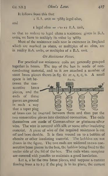
CH. XX.] Ohm's Law. 427
FIG 61.
It follows from this that
i 13.A. unit = '9889 legal ohm,and
i legal ohm = 1-0112 B.A. unit,
so that to reduce to legal ohms a resistance given in B.A.
units, we have to multiply its value by -9889.
Most of the resistance coils now in existence in Englandwhich are marked as ohms, or multiples of an ohm, are
in reality B.A. units, or multiples of a B.A. unit.
On Resistance Boxes.
For practical use resistance coils are generally grouped
together in boxes. The top of the box is made of non-
conducting material, and to it are attached a number of
stout brass pieces shewn in fig. 61 at A, B, c, D. A small
space is left be-
tween the con-
secutive brass
pieces, and the
ends of these
pieces are groundin such a waythat a taper plugof brass can be inserted between them and thus put the
two consecutive pieces into electrical connection. The coils
themselves are made of German-silver or platinum-silver
wire. The wire is covered with silk or some other insulating
material. A piece of wire of the required resistance is cut
off and bent double. It is then wound on to a bobbin of
ebonite or other insulating material. The bobbins are not
drawn in the figure. The two ends are soldered to two con-
secutive brass pieces in the box, the bobbin being fixed to the
under side of the lid of the box. The coils when completeare covered with paraffin to maintain a good insulation.
Let A, B be the two brass pieces, and suppose a current
flowing from A to B;
if the plug is in its place, the current
428 Practical Physics. [Cn. XX.
can pass through it, and the resistance between A and B is
infinitesimally small, provided always that the plug fits
properly. If, however, the plug be removed, the current has
to flow through the coil itself; so that by removing the plug
the resistance of the coil may be inserted in the circuit
between A and B.
The coils in a box are generally arranged thus :122510 10 20 50ioo ioo 200 500 units, &c.
Thus, if there be the twelve coils as above, by taking out
suitable plugs we can insert any desired integral number of
units of resistance between i and 1000, like weights in the
balance. Binding screws, s, s', are attached to the two
extreme brass pieces, and by means of these the box can be
connected with the rest of the circuit.
The coils are wound double, as described, to avoid the
effects which would otherwise arise from self-induction,1 and
also to avoid direct magnetic action on the needle of the
galvanometer.
On the Relation between the Resistance and Dimensions
ofa Wire ofgiven Material.
We have seen that if two conductors be joined in series
the resistance of the combination is the sum of the resist-
ances of the parts. Let the conductor be a long wire of
uniform material and cross-section. Then it follows from the
above (p. 422) that the resistance is proportional to the length;
for if we take two pieces of the same length they will have
the same resistance, and if connected end to end the resist-
ance of the double length is double that of the single. Thusthe resistance is proportional to the length.
Again, we may shew that the resistance is inversely
proportional to the area of the cross-section. For supposetwo points, A and B, are connected by a single wire, the
1 See S. P. Thompson's Elec. and Mag., 404 ; Jenkin, Elcc. and
Mag. , pp. 74, 232.
CIT. xx.] OJurfs Law. 429
resistance of which is R. Introduce a second connecting
wire of the same length and thickness, and therefore of the
same resistance as the former. The resistance will nowTJ
be, and since it was found by Ohm that the resistance
depends on the area of the cross-section and not on its
form, we may without altering the result suppose the two
wires, which have been laid side by side, welded into one,
having a cross-section double of that of either wire.
Thus, by doubling the cross-section the resistance is
halved. The resistance, therefore, varies inversely as the
area of the cross-section.
DEFINITION OF SPECIFIC RESISTANCE. Consider a cube
of conducting material having each edge one centimetre in
length. Let two opposite faces of this be maintained at
different potentials, a current will be produced through the
cube, and the number of units in the resistance of the cube
is called the specific resistance of the material of which the
cube is composed.Let p be the specific resistance of the material of a piece
of wire of length / and cross-section a, and let R be the
resistance of the wire. ThenR = p 11a.
For, suppose the cross-section to be one square centimetre,
then the resistance of each unit of length is p and there are
/ units in series;thus the' whole resistance is p I. But the
resistance is inversely proportional to the cross-section, so
that if this be a square centimetres, the resistance R is given
by the equationR = p 11 a.
Again, it is found that the resistance of a wire dependson its temperature, increasing in most cases uniformly with
the temperature for small variations, so that if RO be the
resistance at a temperature zero and R that at temperature /,
we have
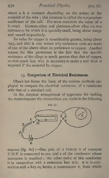
430 Practical Physics. [Cii. XX.
where a is a constant depending on the nature of the
material of the wire;this constant is called the temperature
coefficient of the coil. For most materials the value of a
is small. German-silver and platinum-silver alloy are two
substances for which it is specially small, being about -00032and '00028 respectively.
Its value for copper is considerably greater, being about
003, and this is one reason why resistance coils are madeof one of the above alloys in preference to copper. Another
reason for this preference is the fact that the specific
resistance of the alloys is much greater than that of copper,so that much less wire is necessary to make a coil than is
required if the material be copper.
75. Comparison of Electrical Resistances,
Ohm's law forms the basis of the various methods em-
ployed to compare the electrical resistance of a conductor
with that of a standard coil.
In the simplest arrangement of apparatus for makingthe measurements the connections are made in the following
FIG. 62
manner (fig. 62) : One pole of a battery B of constant
E.M.F. is connected to one end A of the conductor whose
resistance is required ;the other end c of this conductor
is in connection with a resistance box M N. N is in con-
nection with a key or, better, a commutator K, from which
Cn. xx. 75.] Ohm's Law. 431
the circuit is completed through a galvanometer G to the
other pole of the battery.
Let x be the resistance to be measured, B the battery
resistance, G that of the galvanometer, and suppose a
resistance R is in circuit in the box.
Make contact with the commutator. A current passes
through the galvanometer. Observe the deflexion when the
needle has become steady. Reverse the commutator;the
galvanometer needle is deflected in the opposite direction,
and if the adjustments were perfect, the two deflexions would
be the same. They should not differ by more than o'5.
Adjust R, the resistance in the box, if it be possible, until
the deflexion observed is about 45. Of course it may be
impossible to do this with the means at hand. If when
R is zero the deflexion observed be small, the electro-
motive force of the battery will require to be increased; we
must use more cells in series. If, on the other hand, with
as great a resistance in the box as is possible, the deflexion
be too large, then either the galvanometer must be shunted
or the E.M.F. of the battery reduced by reducing the
number of cells, or by connecting its poles through a shunt.
In any case the deflexion should be between 30 and 60.
Let E be the E.M.F. and k the reduction factor of the
galvanometer, which, we shall suppose, is a tangent instru-
ment. Then, if i be the current, and a the mean of the
two deflexions in opposite directions, we have
= i = k tan a.
B-f-G-fX+ R
Hence
B + G + X4-R = E// tan a . . . (i)
and if B, G, E, and k be known, R and a being observed,
this equation will give us x.
If E and k be not known, while B and G are, we proceedthus. Take the unknown resistance x out of the circuit,
connecting one pole of the battery with the electrode M
43 2 Practical Physics. [Cn. xx. 75.
of the resistance box. Take a resistance R' out of the
box and observe the deflexion, which, as before, should lie
between 30 and 60, reversing the current and readingboth ends of the needle ; let the mean deflexion be a'.
Then we have, as before, if the battery have a constant
E.M.F.,E 7 . .-. = k tan a! :
B + G+ R'
na' ... (2)
so that the original equation (i) becomes
n a'/tan a, ... (3)
and from this x can be found.
But in general B and G will not be known. We can
easily find the sum B+ G as follows :
Make two sets of observations exactly in the same
manner as the last were made, with two different resistance?
R I}R2 out of the box, and let the deflexions be a
Land a2 ;
GJ may be just over 30, o 2 just under 60.
[There should be a large difference between c^ and a2 ,for
we have to divide, in order to find the result, by tan a2 tan 04,
and, if this be small, a large error may be produced.]
Then, assuming as before that the E.M.F. of the
battery does not alter, we have
and
= k tan 2 . ... (5)
Hence
(B + G+ RJ) tan c^= 5 =(n + G -f R 2)
tan a2,
and
tan aa tan al
CH. XX. 75.] Ohm's Laiv. 433
Having thus found B+ G, we may use either of the equa-tions
( 4} or( 5) in combination with (i) to give us x.
If we wish to find B and G separately we may proceedas follows :
Shunt the galvanometer with a shunt of resistance s;
then the resistance between the poles of the galvanometeris equivalent to GS/(S-}-G). Make two more observations
like those from which equations (4) and (5) are deduced, wethus find a value for B+ GS/(S + G).
Suppose we find
B+ JLL.= .,S + G
having already obtained
when y is written for the right-hand side of equation (6).
HenceG sG- - =y z;S + G
thus
or
Thus, G paving been found, B is given from the equation
The methods here given for measuring resistance, in-
volving, as they do, the assumption that the E M.F. of the
battery remains the same throughout, cannot be considered
as completely satisfactory. Others will be given in 77-79,which are free from the objections which may be urged
against these. Various modifications of the above methods
have been suggested for measuring more accurately the
resistance of a battery or galvanometer. For an account
of these the reader is referred to Kempe's 'Handbook of
F F
434 Practical Physics. [CH. XX. 75.
Electrical Testing,' chapters v. and vi. In practice muchis gained by a little judgment in the choice of the resistances
taken from the box. Thus, in finding B+ G as above it might
happen that when R 2 is 19, a 2 is 59 30', and when R 2 is 20,
a2 is 58 45'. Now the tangent of either of these angles
can be looked out equally easily in the tables, but the
multiplication involved in finding R 2 tana2 is much more
easily done if R2 be 20 than if it be 19.
Experiment. Determine the resistance of the given coil X.
Enter results thus :
Observations to find B + G.
Rx= 20 ohms. Q!
= 57
Whence B + G = 3*37 ohms.
Observations to find x.
R = 10 ohms. a =460>52
Whence x = 2i'6 ohms.
N.B. If a large number of resistances have to be deter-
mined by the use of the same galvanometer, it will be best to
calculate the value of B + G, and the ratio of the E.M.F. to the
reduction factor once for all, checking the results occasionally
during the other observations. These are both given by the
observations just made, for we have found B t G, and we have
E = ^tanaaB + G + R!
/.-^=(B + G + RJ) tan u
x.
With the numbers in the above example,
and we find
i-S75
^35-97.
CH. XX. 75.] Ohm's Law. 435
So that, if we find, with an unknown resistance X in circuit and a
resistance R out of the box, that the deflexion is a, we obtain
_,k tan a tan a
76. Comparison of Electromotive Forces,
We may moreover use Ohm's law to compare the electro-
motive forces of batteries. 1 For suppose we have two bat-
teries ; let B, B' be their resistances, E, E' their electromotive
forces. Pass a current from the two batteries in turn throughtwo large resistances, R andR' and the galvanometer, and let
the deflexions observed be a, a!. Suppose the galvanometerto be a tangent instrument. Then, if k be its reduction factor,
G its resistance, we have
n a,
E' = k(v'+ G -t- R') tan a'.
Hence
E__ (s + G+R)tana
and B+ G, B'+ G being determined as in the last section,
the quantities on the right-hand side are all known.
In practice there are some simplifications. A Thomson's
reflecting galvanometer is usedtand this is so sensitive that
R and R' will need to be enormously large to keep the spotof light on the scale. The values will be probably from
eight to ten thousand ohms if only single cells of the batteries
in ordinary use be employed. Now the resistance of such
a cell will be very small compared with these ;an ordinary
quart Daniell should be under one ohm ; a Leclanche
from one to three ohms;and hence we may neglect B and
B' as compared with R and R', and we have
E __ (R+ G) tan a
E7~~
(R' -f G) tan a!'
1 See p. 425.F F2
436 Practical Physics. [CH. XX. 76.
This equation is applied in two ways :
(1) The Equal Resistance Method. The resistance R' is
made equal to R, i.e. the two batteries are worked through
the same external circuit, and we have then
E tan a
E' tan a!
But if the angles a, a! be not too large, the scale-de-
flexions of the spot of light are very nearly proportional to
tan a and tan a'. Let these deflexions be 8 and 8' respec-
tively, thenE 8
E'
~~ FFor this method we do not need to know the galvano-
meter resistance, but we suppose that the galvanometer is
such that the displacement of the spot is proportional to
the current.
(2) The Equal Deflexion Method. In this method of
working a! is made equal to a, and we have
E _ R+ CLif'
~~R' + G
For this method we require to know G, or, at any rate,
to know that it is so small compared with R and R' that we
may neglect it. The method has the advantage that we do
not assume any relation between the current in the galvano-
meter and the deflexion produced, except that the same
current produces the same deflexion ;and this is obviously
true whatever be the form of the instrument.
Both methods are open to the objection that the E.M.F.
of a battery which is actually producing a current changes
from time to time. We shall see in 80 how to comparethe E.M.F. of batteries without allowing them to producea current.
Experiments.
Compare the E.M.F. of the given batteries by the equal resist-
ance and the equal deflexion methods, and taking the E.M.F. of
CH. xx. 76.] Ohm' s Law. 437
the Daniell's cell as 1*08 volts, find the E.M.F. of the others in
volts.
Enter results thus :
Equal Resistance Method. Resistance used, 10,000 ohms.
Internal resistance of cells, small.
Battery Deflexions in E.M.F. in
scale divisions volts
Daniell ... 46 ro8
Sawdust Daniell . . 35 -82
Leclanche ... 52 1-22
Bichromate... 68 I '60
Equal Deflexion Method. Deflexion, 83 scale divisions.
Galvanometer resistance, small.
Battery Resistance E.M.F. in
volts
Daniell . . . 8000 roS
Sawdust Daniell . . 6020 -Si
Leclanche . . . 9040 1-22
Bichromate. . . 11980 1-61
77. Wheatstone's Bridge.
The method of comparing electrical resistances which
has been already described depends on the measurement
of the deflexion produced in a galvanometer, and we makethe assumptions that the E.M.F. of the battery remains con-
stant during the experiment, and that the relation between
the current flowing through the galvanometer and the de-
flexion it produces is known. The disadvantages which thus
arise are avoided in the Wheatstone bridge method, the
principles of which we proceed to describe.
It follows from Ohm's law (p. 420) that, if a steady cur-
rent be flowing through a conductor, then the electromotive
force between any two points of the conductor is propor-tional to the resistance between those points. We can
express this graphically thus. Let the straight line A B (fig.
63) represent the resistance between the two points A and
B of a conductor, and let the line A D, drawn at right angles
to A B, represent the electromotive force or difference of
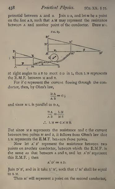
433 Practical Physics. [CH. XX. 77.
potential between A and B. Join D B, and let M be a point
on the line A B, such that A M may represent the resistance
between A and another point of the conductor. Draw M L
FIG. 63.
M
at right angles to A B to meet B D in L, then L M represents
the E.M.F. between M and B.
For if c represent the current flowing through the con-
ductor, then, by Ohm's law,
DA
and since M L is parallel to D A,
DAAB
LMMB*
.'. L M = C X M B.
But since M B represents the resistance and c the current
between two points M and B, it follows from Ohm's law that
LM represents the E.M.F. between those points.
Now let A' B' represent the resistance between two
points on another conductor, between which the E.M.F. is
the same as that between A and B, and let A' D' representthis E.M.F.
; then
A' D' = A D.
Join D' B', and in it take L' M', such that L' u f
shall be equalto L M.
Then M' will represent a point on the second conductor,
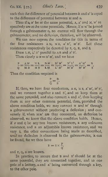
CH. XX. 77.] Ohm's Law.\ 439
such that the difference of potential between it and B' is equal
to the difference of potential between M and B.
Thus if B, B' be at the same potential, A, A' and M, M' re
spectively are at the same potentials. Hence, if M M' be joined
through a galvanometer G, no current will flow through the
galvanometer, and no deflexion, therefore, will be observed.
We can now express the condition for this in terms of
the four resistances A M, M B, A' M', M' B', Let these
resistances respectively be denoted by P, Q, R, and s.
Draw L N, L' N' parallel to A B and A' B'.
Then clearly D N = D' N', and we have
P__AM_NL_DN__D'N / _ N'L' _ A' M' _ R
Q MB MB L M I/ M' M' B' M' B' S*
Thus the condition required is
p _ R
Q~S*
If, then, we have four conductors, A M, M B, A' M', M' B',
and we connect together B and B', and so keep them at
the same potential, and also connect A and A7
,thus keeping
them at any other common potential, then, provided the
above condition holds, we may connect M and M' througha galvanometer without producing a deflexion ;
and con-
versely if, when M M' are thus connected, no deflexion be
observed, we know that the above condition holds. Hence,if P and Q be any two known resistances, R any unknown
resistance, and s an adjustable known resistance, and we
vary s, the other connections being made as described,
until no deflexion is observed in the galvanometer, R can
be found, for we then havep
R = SX -,Q
and P, Q, s are known.
In practice, to secure that B and B' should be at the
same potential, they are connected together, and to one
pole of a battery, A and A' being connected through a key,
to the other pole.
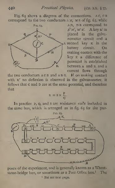
440 Practical Physics. [CH. XX. 77.
Fig. 64 shews a diagram of the connections. A c, c B
correspond to the two conductors AM, MB of fig. 63, while
AD, D B correspond to
A' M', M' B'. A key K' is
placed in the galva-
nometer circuit and a
,A second key K in the
battery circuit. Onmaking contact with the
key K a difference of
potential is established
between A and B, and a
current flows throughthe two conductors A c B and A D B. K on making contact
with K' no deflexion is observed in the galvanometer, it
follows that c and D are at the same potential, and therefore
that
R-SX*Q
In practice P, Q, and s are resistance coils included in
the same box, which is arranged as in fig. 65 for the pur-
FIG. 65.
oooooooc
poses of the experiment, and is generally known as a Wheat-
stone-bridge box, or sometimes as a Post- Office box. 1 The1
13 ul see next page.
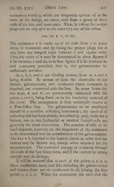
Cn. XX. 77.] Ohm's Law. 441
resistances p and Q, which are frequently spoken of as the
arms of the bridge, are taken, each from a group of three
coils of 10, zoo, and 1000 units. Thus, by taking the proper
plugs out we may give to the ratio P/Q any of the values
100, 10, i, "i, or 'oj.
The resistance s is made up of 16 coils from i to 5,000
ohms in resistance, and by taking the proper plugs out it
may have any integral value between i and 10,000 units.
Thus the value of R may be determined to three figures if
it lie between i and 10, or to four figures if it be between 10
and 1,000,000, provided, that is, the galvanometer be
sufficiently sensitive.
At A, B, c, and D are binding screws, those at A and D
being double. By means of these the electrodes of the
battery, galvanometer, and conductor whose resistance is
required, are connected with the box. In some boxes the
two keys, K and K', are permanently connected with the
points A and c, being fixed on to the insulating material of
the cover. The arrangement is then technically known as
a Post- Office box. The galvanometer to be employedshould be a sensitive reflecting instrument
;the method of
adjusting this has been already described (p. 404), while for a
battery, one or two Leclanche or sawdust Daniell cells are
generally the most convenient. The number of cells to be
used depends, however, on the magnitude of the resistance
to be determined and the sensitiveness of the galvanometer.The key K is inserted in the battery circuit in order that the
battery may be thrown out, except when required for the
measurement. The continual passage of a current throughthe coils of the box heats them, and if the current be strong
enough may do damage.It wilt be noticed that at each of the points A, B, c, D,
three conductors meet, and that including the galvanometerand battery there are six conductors in all, joining the four
points A, B, c, D. When the resistances are such that the
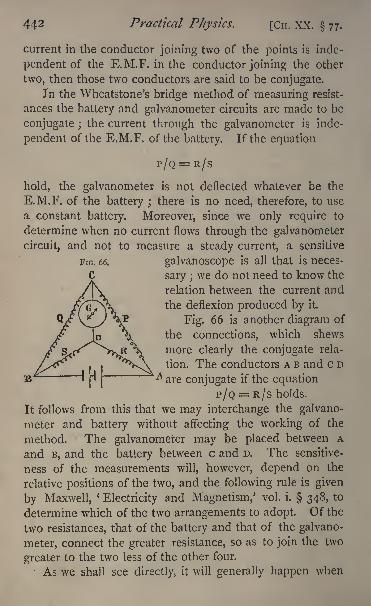
442 Practical Physics. [Cn. XX. 77.
current in the conductor joining two of the points is inde-
pendent of the E.M.F. in the conductor joining the other
two, then those two conductors are said to be conjugate.In the Wheatstone's bridge method of measuring resist-
ances the battery and galvanometer circuits are made to be
conjugate ; the current through the galvanometer is inde-
pendent of the E.M.F. of the battery. If the equation
P/Q = R/S
hold, the galvanometer is not deflected whatever be the
E.M.F. of the battery ; there is no need, therefore, to use
a constant battery. Moreover, since we only require to
determine when no current flows through the galvanometer
circuit, and not to measure a steady current, a sensitive
galvanoscope is all that is neces-
sary ;we do not need to know the
relation between the current and
the deflexion produced by it.
Fig. 66 is another diagram of
the connections, which shews
more clearly the conjugate rela-
tion. The conductors A B and c D
are conjugate if the equation
P/Q = R/S holds.
It follows from this that we may interchange the galvano-
meter and battery without affecting the working of the
method. The galvanometer may be placed between A
and B, and the battery between c and D. The sensitive-
ness of the measurements will, however, depend on the
relative positions of the two, and the following rule is given
by Maxwell,'
Electricity and Magnetism,' vol. i. 348, to
determine which of the two arrangements to adopt. Of the
two resistances, that of the battery and that of the galvano-
meter, connect the greater resistance, so as to join the two
greater to the two less of the other four.
As we shall see directly, it will generally happen when
CH. XX. 77.] Ohm's Law. 443
making the final measurements, that Q and s are greater
than p and R; thus, referring to fig. 65, the connections are
there arranged to suit the case in which the resistance of
the battery is greater than that of the galvanometer.
To measure a Resistance with the Wheatstone-bridge Box.
Make the connections as shewn in fig. 65. Be sure that
the binding screws are everywhere tight and that the copperwires are clean and bright at all points where there are
contacts. This is especially necessary for the wires which
connect R to the box. Any resistance due to them or their
contacts will of course be added to the value of R. For
delicate measurements contacts must be made by means of
thick copper rods amalgamated with mercury, and dippinginto mercury cups. The bottoms of the cups should be
covered with discs of amalgamated copper, and the wires
must press on to these with a steady pressure throughoutthe experiment; it is not sufficient to make the contact
through the mercury by letting the wires drop into it without
touching the copper bottom. The cups themselves are
conveniently made of pill boxes, covered with a good thick
coat of varnish.
See that all the plugs are in their places in the box, and
press them firmly in with a screw motion to ensure efficient
contact. .
Bring the control magnet of the galvanometer downnear the coils, and if the resistance to be measured be not
even approximately known, it generally saves time to shunt
the galvanometer, using the shunt, provided there be one,if not, a piece of thin German-silver wire. Take two equalresistances out of the arms P and Q. Since it is probablethat the galvanometer will be somewhat too sensitive evenwhen shunted, it is better to take out the two 100 ohmplugs rather than the two 10 ohms. Then, since P = Q,R will be equal to s.
Take i ohm out from s. Make contact first with the
444 Practical Physics. [CH. XX. 77.
battery key K, and then with the galvanometer key K', andnote the direction of the deflexion suppose it be to the right.
Take out 1000 ohms from s, and note the deflexion
suppose it be to the left. The resistance is clearly between
i and 1000 ohms.
Now take out 500 ohms let the deflexion be to the
left R is less than 500. Proceed thus, and suppose that
with 67 ohms the deflexion is to the left, and that with 66
ohms it is to the right. The resistance R is clearly between
66 and 67 ohms.
Now make p 10 ohms and Q 100, and at the same time
remove the shunt, and raise the galvanometer magnet to
increase the sensitiveness. Since Q is ten times p, s must
be ten times R to obtain a balance. Thus s must be
between 660 and 670. Suppose that it is found that with
665 ohms the deflexion is to the left, and with 664 it is to
the right, the true value of s is between 664 and 665,
and since R = PS/Q, the true value of R is between 66*4
and 66-5. We have thus found a third figure in the value
of R.
Now make Q 1000 ohms and p 10 ohms. Then, since Qis 100 times P, s must be 100 times R to secure the balance;and it will be found that when s is 6640 the deflexion is to
the right ;when it is 6650 it is to the left. The galvano-
meter may now be made as sensitive as possible ; and it
will probably be found that with a value of s, such as 6646,
there is a small deflexion to the right, and with s equal to
6647 a small deflexion to the left. Thus the value of R is
between 66*46 and 66*47.
If the fourth figure be required correctly, we may find it
by interpolation as follows :
When s is 6646 let the deflexion to the right be a
scale divisions, and when it is 6647 ^et ^ be ^ divisions to
the left. Then since an addition of i ohm to the value of
R alters the reading by a + b scale divisions, it will require
an addition of a/(a + l^)ohms to alter it by a divisions.
CH. XX. 77.] Ohm's Law. 445
Thus the true value of R is 6646 + a\ (a + ) ohms, and the
value of s is
66'46 + a/ioo(a-{-l>) ohms.
The exactness to which the determination can be carried
will depend on the accuracy with which the small out-
standing deflexions a and b can be read, and on the con-
stancy of the battery.
If it be found that the resistance R is less than i ohm,make P 100 ohms, and Q 10
;then the value of s will be ten
times that of R, and if we find that s lies between 5 and 6,
it follows that R is between '5 and -
6;then make P 1000
ohms, and Q 10, and proceed similarly.
After making the determination the connecting wires
must all be removed from the box and the plugs replaced.
Experiment. Determine the values of the resistances in
the given box.
Enter results thus :
Nominal value Real value
10 ohms . . . 10-03 ohms20 . . . 20-052
50 . . . 50-005ioo ... 100-13
Measurement of a Galvanometer Resistance Thomson's
Method.
It has been shewn that if, in the Wheatstone's bridge
arrangement, two of the conductors, as AB, CD (fig. 66,
p. 442), are conjugate, then the current through the one dueto an E.M.F. in the other is zero. It follows from this that
the current through the other conductors is independent of
the resistance in c D, and is the same whether c D be con-
nected by a conductor or be insulated;
for the condition
that the two should be conjugate is that c and D should beat the same potential, and if this condition be satisfied there
will never be any tendency for a current to flow along CD ;
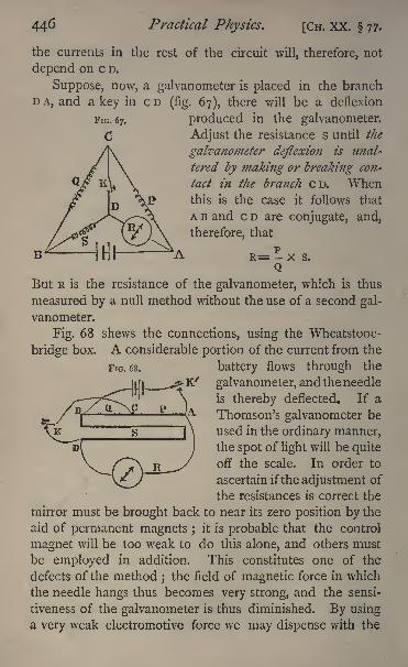
446 Practical Physics. [CH. XX. 77.
the currents in the rest of the circuit will, therefore, not
depend on c D.
Suppose, now, a galvanometer is placed in the branch
DA, and a key in CD (fig. 67), there will be a deflexion
produced in the galvanometer.
Adjust the resistance s until the
galvanometer deflexion is unal-
tered by making or breaking con-
tact in the branch CD. Whenthis is the case it follows that
A B and c D are conjugate, and,
therefore, that
pR= - x s.
Q
But R is the resistance of the galvanometer, which is thus
measured by a null method without the use of a second gal-
vanometer.
Fig. 68 shews the connections, using the Wheatstone-
bridge box. A considerable portion of the current from the
battery flows through the
galvanometer, and the needle
is thereby deflected. If a
Thomson's galvanometer be
used in the ordinary manner,the spot of light will be quite
off the scale. In order to
ascertain if the adjustment of
the resistances is correct the
mirror must be brought back to near its zero position by the
aid of permanent magnets ; it is probable that the control
magnet will be too weak to do this alone, and others must
be employed in addition. This constitutes one of the
defects of the method ; the field of magnetic force in which
the needle hangs thus becomes very strong, and the sensi-
tiveness of the galvanometer is thus diminished. By using.
a very weak electromotive force we may dispense with the
FIG. 68.
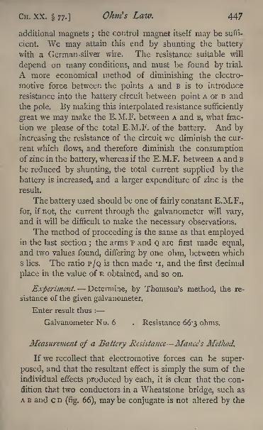
CH. xx. 77.] Ohm's Law. 447
additional magnets ;the control magnet itself may be suffi-
cient. We may attain this end by shunting the battery
with a German-silver wire. The resistance suitable will
depend on many conditions, and must be found by trial.
A more economical method of diminishing the electro-
motive force between the points A and B is to introduce
resistance into the battery circuit between point A or B and
the pole. By making this interpolated resistance sufficiently
great we may make the E.M.F. between A and B, what frac-
tion we please of the total E.M.F. of the battery. And by
increasing the resistance of the circuit we diminish the cur-
rent which flows, and therefore diminish the consumptionof zinc in the battery, whereas if the E.M.F. between A and B
be reduced by shunting, the total current supplied by the
battery is increased, and a larger expenditure of zinc is the
result.
The battery used should be one of fairly constant E.M.F.,
for, if not, the current through the galvanometer will vary,
and it will be difficult to make the necessary observations.
The method of proceeding is the same as that employedin the last section
;the arms p and Q are first made equal,
and two values found, differing by one ohm, between which
s lies. The ratio P/Q is then made *i, and the first decimal
place in the value of R obtained, and so on.
Experiment. Determine, by Thomson's method, the re-
sistance of the given galvanometer.
Enter result thus :
Galvanometer No. 6 . Resistance 66'3 ohms.
Measurement of a Battery Resistance Mance's Method.
If we recollect that electromotive forces can be super-
posed, and that the resultant effect is simply the sum of the
individual effects produced by each, it is clear that the con-
dition that two conductors in a Wheatstone bridge, such as
A B and c D (fig. 66), may be conjugate is not altered by the

448 Practical Physics. [CH. XX. 77.
introduction of a second battery into any of the arms of
the bridge. Such a battery will of course send a current
through the galvanometer, and produce a deflexion, which
will be superposed on that due to the battery in A B. Let
a battery be put in the arm A D (fig. 69), R being its resist-
ance, and let the galvanometer needle be brought back to
its zero position by the use of external magnets. Adjustthe resistance s until making or breaking contact in the
battery circuit A B produces no effect on the galvanometer ;
that is, until the circuits A B and c D are conjugate. Whenthis is the case we have
R = P s/Q ;
and P, s, and Q being known, we can find R, the resistance
of the battery.
There is, however, no need for a second battery in A B;
for the effect on the galvanometer due to this battery is
zero when the conjugate condition is satisfied, whatever be
its E.M.F. Take then the case when the E.M.F. is zero,
i.e. connect A and B directly through a conductor. If the
conjugate condition be satisfied this will produce no effect
on the galvanometer ;the deflexion due to the battery in
A D will not be altered.
Again take the case in which the E.M.F. producedbetween A and B by the battery in A B is exactly equal
and opposite to that produced between those points by the
battery in A D. The galvanometer deflexion will still, if the
conjugate condition hold, be unaltered. But in this case
no current flows along A B;the conditions are the same as
if A and B were insulated.
Thus the battery in A B may be supposed removed and
replaced by a key. If the resistance s be adjusted until no
effect is produced on the galvanometer by making con-
tact with this key, it follows that the conjugate condition
holds, and therefore R = PS/Q, so that R is determined.
This is the principle of Mance ;
s method.
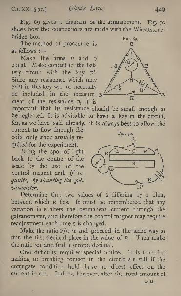
CH. XX. 77.] OJiui's Law. 449
K
Fig. 69 gives a diagram of the arrangement. Fig. 70shews how the connections are made with the Wheatstone-
bridge box.
The method of procedure is
as follows :
Make the arms P and Q
equal. Make contact in the bat-
tery circuit with the key K'.
Since any resistance which mayexist in this key will of necessity
be included in the measure- Bment of the resistance R, it is
important that its resistance should be small enough to
be neglected. It is advisable to have a key in the circuit,
for, as we have said already, it is always best to allow the
current to flow through the
coils only when actually re-
quired for the experiment.
Bring the spot of light
back to the centre of the
scale by the use of the
control magnet and, if re-
quisite^ by shunting the gal-
vanometer.
Determine thus two values of s differing by i ohm,between which R lies. It must be remembered that anyvariation in s alters the permanent current through the
galvanometer, and therefore the control magnet may require
readjustment each time s is changed.Make the ratio P/Q 'i and proceed in the same way to
find the first decimal place in the value of R. Then makethe ratio '01 and find a second decimal.
One difficulty requires special notice. It is true that
making or breaking contact in the circuit A B will, if the
conjugate condition hold, have no direct effect on the
current in c D. It does, however, alter the total amount of
G G
45O Practical Physics. [CH. XX. 77.
current which is being produced by the battery. When A D
is closed an additional circuit is open for this current;now
with most batteries the E.M.F. depends somewhat on the
current which the battery is producing, that is, on the rate
at which chemical changes are going on in it;so that when
the battery is called upon to do more work by the closing of
the circuit AB, its E.M.F. is gradually altered and the
permanent deflexion is thereby changed. On making con-
tact with the key the spot of light may move, not because
the conjugate condition is not satisfied, but because of this
change in the E.M.F. of the battery. This is a funda-
mental defect in the method, and prevents the attainment
of results of the highest accuracy. The difficulty may be
partially obviated as follows : It will be found that the
displacement produced through the conjugate condition not
being satisfied is a somewhat sudden jerk, while that which
arises from variation in the E.M.F. is more gradual in its
nature. A little practice is all that is required to recognise
the difference between the two. Now it will always be
possible to arrange the resistances so that the two displace-
ments are in opposite directions. Let us suppose that it is
found that when s is too large on making contact the jerk
is to the right ; the gradual deflexion to the left. Graduallydecrease s until the jerk appears to be zero, and the spot
seems to move steadily to the left, and take the value of s
thus found as the one required. The results thus obtained
will be found fairly consistent.
A more exact method for overcoming the difficulty, due
to Professor O. J. Lodge, was described by him in the ' Phi-
losophical Magazine' of 1876. This, however, involves the
use of a specially constructed key, and for an account of it
the reader must be referred to the original paper.
Experiment. Determine by Mance's method the resistance
of the given battery.
Enter results thus :
I Leclanche cell (a) . . . . 1-21 ohm
CH. XX. 77.] Ohm's Law. 45 1
I Leclanche cell (o] . . . . rog ohmi Sawdust Daniell .... 10-95
i Cylinder Daniell . . . . -58
78. The British. Association Wire Bridge. Measurementof Electrical Resistance.
The apparatus used for measuring resistances by the
Wheatstone-bridge method frequently takes another form.
The theory of the method is of course the same as whenthe box is employed, but instead of varying the resistance
s, the ratio P/Q is made capable of continuous alteration.
The conductors B c, c A of figure 64 are two portions of
a straight wire of platinum- silver or German-silver, or someother material of a high specific resistance, which is care-
fully drawn so as to have a uniform cross-section, the re-
sistance of any portion of such a wire being proportional to
its length. The ratio of the resistances P/Q will be the
ratio of the two lengths A C/B c.
A sliding-piece or jockey moves along this wire, and by
pressing a spring attached to it electrical connection with the
galvanometer can be made at any desired point c of A B.
Thus the ratio of A c to B c can be made to have any value
by altering the position of the point c along this wire.
A scale, usually divided to millimetres, is fixed parallel
to the wire. ; the ends of the wire A and B coincide with the
extremities of the scale;and the position of the point c,
at which the contact is made, can be read by means of a
mark on the sliding-piece. The ends of this wire are fixed
to stout copper pieces, by means of which connection is
made with the resistances R and s. These copper strips
are so thick that for many purposes their resistance may be
neglected when compared with that of the wire A c B.
The apparatus usually takes the form shewn in fig. 71.
The strips N M A, N' M' B are the stout copper pieces
just referred to. It will be noticed that there are gaps left
between M and A, M' and B; their purpose will be explained
GG 2
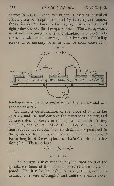
452 Practical Physics. [CH. XX. 78,
shortly (p. 454). When the bridge is used as described
above, these two gaps are closed by two strips of copper,
shewn by dotted imes in the figure, which are screwed
tightly down to the fixed copper pieces. The wire R, whose
resistance is required, and s, the standard, are electrically
connected with the apparatus, either by means of binding
screws or of mercury cups, as may be most convenient;FIG. 71.
binding screws are also provided for the battery and gal-
vanometer wires.
To make a determination of the value of R, close the
gaps A M and B M' and connect the resistances, battery, and
galvanometer, as shewn in the figure. Close the battery
circuit by the key K. Move the jockey c until a posi-
tion is found for it, such that no deflexion is produced in
the galvanometer on making contact at c. Let a and b
be the lengths of the two pieces of the bridge wire on either
side of c. Then we have
andR =
The apparatus may conveniently be used to find the
specific resistance of the material of which a wire is com-
posed. For if R be the resistance, and p the specific re-
sistance of a wire of length / and uniform circular cross-
Cn. XX. 78.]OJnrfs Law. 453
section of diameter d, then the area of the cross-section is
,and we have
so that
_
The value of R can be found by the method just
described. The length of the wire may be measured with
a steel tape, or other suitable apparatus, and the diameter dcan be determined by the aid of the screw gauge. For great
accuracy this method of finding the diameter may not be suffi-
cient. It may be more accurately calculated from a know-
ledge of the mass, length, and density of the wire (see 8).
The determination of R by the method just described
is not susceptible of very great accuracy. The position of c
cannot be found with very great exactness, and an error in
this will produce very considerable error in the result.
It can be shewn as follows that the effect of an error xin the position of c produces least effect in the result when
c is the middle point of the wire.
For let c be the whole length of the wire \then we have
found that
R=S^-c a
Suppose that an error x has been made in the position
of c, so that the true value of a is a+x. Then the true
value of R is R+ X, say, where
c a x
Hence if we neglect terms involving x2 we have
^-J = R 1 1 + -/-- Iaca} ( a(ca)\
454 Practical Physics. [CH. XX. 78.
Now it is shewn in books on Algebra that a(ca) is greatest
when a = ca, that is, when a = \c, or c is at the middle
point of the bridge-wire ;and in this case the ratio of x to R,
that is, the ratio of the error produced by an error x in a to
the resistance measured, is least when c is at the middle point.
Thus the standard chosen for s should have approximatelythe same value as R. This may be conveniently arrangedfor by using a resistance-box for s and taking out plugs until
the adjusted position of c is near the middle of the wire.
But even with this precaution the method is far from
sensitive;the resistance of the wire N N' is probably very
small compared with the resistances R and s. Nearly all
the current flows directly through the wire, and very little
through the coils R and s. The greatest possible difference
of potential between c and D is small, and the deflexion of
the galvanometer will always be small.
To remedy this two other resistance coils are inserted in
the gaps AM and BM', the copper strips being removed.
Suppose their resistances respectively are p' and Q', and
suppose that the value of R is known approximately, or has
been found from a rough observation as above. The values
of P', Q' must be such the ratio of p' to Q' does not differ
much from that of R to s.
Suppose that when the position of equilibrium is found
the lengths of wire en either side of c are a and b, and that
the resistance of a unit length of the wire is known to be a-.
Then, if we neglect the resistances of the copper strips M N
and M'N' these will be exceedingly small, and may be
neglected without sensible error the value of P will be
p'-{-#cr, and that of Q, Q' + fior, and we have
The value of R is thus determined, and it can be shewn
that the error in the result produced by a given error in the
position of c is much less than when there is no resistance
between A and M, B and M ,
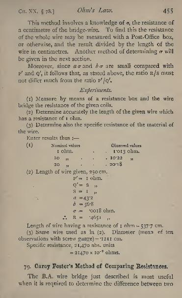
Cn. xx. 78.] Ohm's Law. 455
This method involves a knowledge of /r, the resistance of
a centimetre of the bridge-wire. To find this the resistance
of the whole wire may be measured with a Post-Office box,
or otherwise, and the result divided by the length of the
wire in centimetres. Another method of determining a- will
be given in the next section.
Moreover, since flcrand bcr are small compared with
p' and Q;
,it follows that, as stated above, the ratio R/s must
not differ much from the ratio P'/Q'.
Experiments.
(1) Measure by means of a resistance box and the wire
bridge the resistance of the given coils.
(2) Determine accurately the length of the given wire which
has a resistance of I ohm.
(3) Determine also the specific resistance of the material of
the wire.
Enter results thus :
1I) Nominal values Observed values
I ohm. . . i '013 ohm.10 . . 10-22
20 . . 2O'l8
(2) Length of wire given, 250 cm.
p' = i ohm.
Q'= 2
s = i
a =43-2b =56-8or .= -0018 ohm.
/. R = -4651
Length of wire having a resistance of i ohm = 5377 cm.
(3) Same wire used as in (2). Diameter (mean of ten
observations with screw gauge) = '1211 cm.
Specific resistance, 21,470 abs. units
= 21470 x io~9 ohms.
79. Carey Foster's Method of Comparing Resistances.
The B.A. wire bridge just described is most useful
when it is required to determine the difference between two
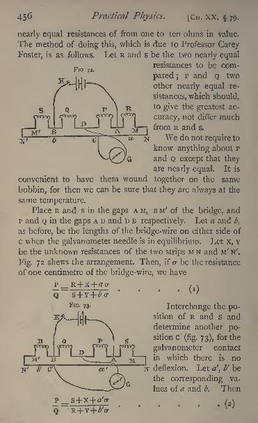
456 Practical Physics. [CH. XX. 79.
FIG 72.
nearly equal resistances of from one to ten ohms in value.
The method of doing this, which is due to Professor Carey
Foster, is as follows. Let R and s be the two nearly equalresistances to be com-
pared ;P and Q two
other nearly equal re-
sistances, which should,
to give the greatest ac-
curacy, not differ muchfrom R and s.
We do not require to
know anything about P
and Q except that theyare nearly equal. It is
convenient to have them wound together on the same
bobbin, for then we can be sure that they are always at the
same temperature.Place R and s in the gaps A M, B M' of the bridge, and
p and Q in the gaps A D and D B respectively. Let a and,
as before, be the lengths of the bridge-wire on either side of
c when the galvanometer needle is in equilibrium. Let x, v
be the unknown resistances of the two strips M N and M' N'.
Fig. 72 shews the arrangement. Then, if cr be the resistance
of one centimetre of the bridge-wire, we have
, ,
Interchange the po-sition of R and s and
determine another po-sition c (fig. 73), for the
galvanometer contact
in which there is no
deflexion. Let a', I' be
the corresponding va-
lues of a and b. Then
N
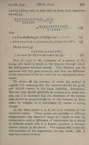
CIT. xx. 79.] Ohm's Law. 457
And by adding unity to each side we have, from equations
(!) and (2)
_ P + Q
'
/ x
Also
a+ b = whole length of bridge wire a'+ b' . . (4)
.-. R4-X-4-rto-+ S + Y+ (T=S+ X-f a'cr+ R+ Y+ l>f(r . (5)
Hence from (3)
.-. R-s = (t-Z>f
)cr= (a'-a)<r, by (4). . . (6)
Now (a1
a) or is the resistance of a portion of the
bridge wire equal in length to the distance through which
the sliding-piece has been moved. This distance can be
measured with very great accuracy, and thus the difference
of the resistances of the two coils can be very exactly deter-
mined.
To obtain all the accuracy of which the method is
capable, it is necessary that the contacts should be good,and should remain in the same condition throughout.
Mercury cups should generally be employed to make con-
tact, and it is necessary that the electrodes of the various
coils should be pressed firmly on to the bottoms of these
either by weights, or, if convenient, by means of spring
clamps.
At the three points c, N, N', we have contacts of two
dissimilar metals. These points are probably at different
temperatures the observer's hand at c tends to raise its
temperature and a difference of temperature in a circuit
of different metals will, it is known, produce a thermo-
electric current in the circuit This current will, under the
circumstances of the experiment, be very small ; still, it
may be a source of error.
45 8 Practical Physics. [Cn. XX. 79.
The best method of getting rid of its effects is to place a
commutator in the battery circuit, and make two observa-
tions of each of the lengths a and #', reversing the battery
between the two. It can be shewn that the mean of the
two observations gives a value free from the error produced
by the thermo-electric effect.
Again, a variation in the temperature of a conductor
produces an alteration in its resistance. For very accurate
work it is necessary to keep the coils R and s at known tem-
peratures. This is generally done by means of a water-bath,
in which the coils are immersed.
It has been found that for most of the metals, at anyrate within ordinary limits of temperature, the change of
resistance per degree of temperature is very nearly constant,
-so that if R be the resistance of a coil at temperature / C.,
RO its resistance at o, and a the coefficient of increase of
resistance per degree of temperature, we have
Carey Foster's method is admirably adapted for finding
this quantity n. The standard coil s is kept at one definite
temperature, and the values of the difference between its
resistance and that of the other coil are observed for two tem-
peratures of the latter. Let these temperatures be t\ and /2 ,
and the corresponding resistances RJ and R 2 ;then we
have
a=(R,-R 2)/R (/1-/2).
The observations have given us the values of Rt
s and
R 2 s with great accuracy, and from them we can get
R! R 2 ;an approximate value of R will be all that is
required for our purpose, for it will be found that a is a very
small quantity, and we have seen (p. 44) that we may with-
out serious error employ an approximate value in the de-
nominator of a small fraction.
Whenever precautions are requisite to maintain the
coils at a uniform temperature, the interchanging of the
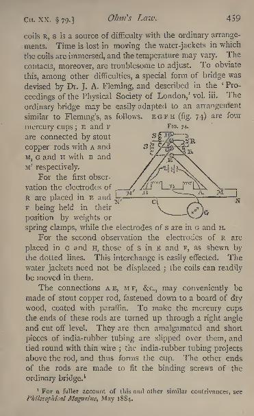
CIT. XX. 79-]OJmfs Laiv. 459
FIG. 74.
coils R, s is a source of difficulty with the ordinary arrange-
ments. Time is lost in moving the water-jackets in which
the coils are immersed, and the temperature may vary. The
contacts, moreover, are troublesome to adjust. To obviate
this, among other difficulties, a special form of bridge was
devised by Dr. J. A. Fleming, and described in the ' Pro-
ceedings of the Physical Society of London,' vol. iii. The
ordinary bridge may be easily adapted to an arrangement
similar to Fleming's, as follows. EGFH (fig. 74) are four
mercury cups ;E and F
are connected by stout
copper rods with A and
M, G and H with B and
M' respectively.
For the first obser-
vation the electrodes of
R are placed in E and f-r
F being held in their
position by weights or
spring clamps, while the electrodes of s are in G and H.
For the second observation the electrodes of R are
placed in G and H, those of s in E and F, as shewn bythe dotted lines. This interchange is easily effected. Thewater jackets need not be displaced ;
the coils can readily
be moved in them.
The connections A E, M F, &c., may conveniently be
made of stout copper rod, fastened down to a board of dry
wood, coated with paraffin. To make the mercury cupsthe ends of these rods are turned up through a right angleand cut off level. They are then amalgamated and short
pieces of india-rubber tubing are slipped over them, and
tied round with thin wire ; the india-rubber tubing projects
above the rod, and thus forms the cup. The other ends
of the rods are made to fit the binding screws of the
ordinary bridge.1
1 For a fuller account of this and other similar contrivances, see
Philosophical Magazine, May 1884.
460 Practical Physics. [CH. XX. 79.
Calibration of a Bridge-wire.
The method gives us also the best means of calibrating
a bridge-wire. Make an observation exactly as above.
Alter the value of p slightly by inserting in series with it a
short piece of German-silver wire. The only effect will be
to shift somewhat the positions of c and c' along the scale,
and thus the difference between R and s is obtained in
terms of the length of a different part of the bridge-wire.
If the wire be of uniform section the two lengths thus
obtained will be the same. If they are not the same, it
follows that the area of the cross-section, or the specific
resistance of the wire, is different at different points, and a
table of corrections can be formed as for a thermometer
(p. 188).
If the difference between the two coils be accurately
known we can determine from the observations the value of
the resistance of a centimetre of the bridge-wire. This is
given by equation (6) ;for the values of R s and a' a
are known, and we have
o-=(R-S)/('-4
For this purpose the following method is often con-
venient. Take two i-ohm coils and place in multiple arc
with one of them a lo-ohm coil. Let the equivalent re-
sistance of this combination be R;then the value of R is
lo/n ohms. Instead of interchanging the coils place the
ten in multiple arc with the other single ohm and make the
observation as before;then in this case we have
10 i i
R s = i : - = ohm.11 ii
and if / be the distance through which the jockey has been
moved we obtain
Ctt. XX. 790 LaW' 4<51
Experiments.
(1) Calibrate the bridge-wire.
(2) Determine the average resistance of one centimetre of it.
(3) Determine accurately the difference between the resist-
ance of the given coil and the standard i-ohm at the tempera-
ture of the room.
Enter results thus :
(1) Value of R-S for calibration, -009901 being the differ-
ence between i ohm and i ohm with 100 in multiple arc-
Position of C Value of a! - a.
Division 20 . . . . 5'4&
40- 5'49
60. . . . 5-5I
80 . . . . 5-52
(2) R~ S = -09091 ohm. / (mean of 5 observations) =
50-51 cm.0- = 'ooi 79 ohm.
(3) Difference between the given coil and the standard at
temperature of I5C, observed three times.
Values -0037, -0036, -00372 ohm. Mean -00367 ohm.
80. PoggendorfFs Method for the Comparison of Electro-
motive Forces. Latimer-Clark's Potentiometer.
The method given in 76 for the comparison of electro-
motive forces is subject to a defect similar to that men-
tioned in 77, on the measurement of resistance ;that is,
it depends upon measuring the deflexion of a galvano-
meter needle, and assumes that the E.M.F. of the batteries
employed remain constant throughout the experimentThe following method, first suggested by Poggendorff,
resembles the Wheatstone-bridge method for measuring
resistances, in being a null method ; it depends, that is to
say, on determining when no current passes through a gal-
vanometer, not on measuring the deflexion. We have seen
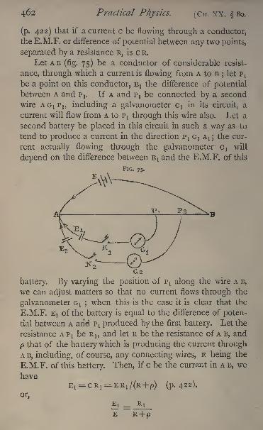
462 Practical Physics. [Cn. XX. 80.
(p. 422) that if a current c be flowing through a conductor,
the E.M.F. or difference of potential between any two points,
separated by a resistance R, is c R.
Let AB (fig. 75) be a conductor of considerable resist-
ance, through which a current is flowing from A to B; let PJ
be a point on this conductor, EJ the difference of potential
between A and pt. If A and PJ be connected by a second
wire AC^P!, including a galvanometer Gt
in its circuit, a
current will flow from A to P! through this wire also. Let a
second battery be placed in this circuit in such a way as to
tend to produce a current in the direction PtG
t A!; the cur-
rent actually flowing through the galvanometer GJ will
depend on the difference between E! and the E.M.F. of this
FIG. 75.
battery. By varying the position of PI along the wire A B,
we can adjust matters so that no current flows through the
galvanometer GJ ;when this is the case it is clear that the
P1M.F. E! of the battery is equal to the difference of poten-
tial between A and PJ produced by the first battery. Let the
resistance A PJ be R,, and let R be the resistance of A B, and
p that of the battery which is producing the current throughA B, including, of course, any connecting wires, E being the
E.M.F. of this battery. Then, if c be the current in A B, we
have
EI = CRI=ER
I /(R+P) (p. 422).
or
Cn. XX. 80.] Ohm's Law. 463
This equation gives us, if we know/>,
the ratio EJ/E;for R and RJ can be observed.
This method will be satisfactory in practice if R is very
great compared with p, for then an approximate value of p
will be sufficient ;or if R is sufficiently large, p may be
entirely neglected, and we may write EI/E= RI /R.
This is PoggendorfFs method of comparing the E.M.F.
of two batteries.
The following arrangement, suggested by Latimer-Clark,
obviates the necessity for knowing p.
Let E!, E2 be the two E.M.F. to be compared, E that of
a third battery, producing a current between the two points
A and B; E must be greater than EJ or E2 . Connect the
three positive poles of the three batteries to A, the negative
pole of E to B, and the negative poles of Etand E2, through
two galvanometers c}and G 2 ,
to two points pj, P2 on AB;adjust the positions of p
land P2 separately until no current
flows through either galvanometer. It will be found con-
venient to have two' keys, K l5K 2 ,
in the circuits for the pur-
poses of this adjustment. Thus, positions are to be found
for P! and P 2 ,such that on making contact simultaneously
with the two keys there is no deflexion observed in either
galvanometer. Let Rb R 2 be the resistances of AP I?A P 2
respectively, when this is the case. Then, c being the cur-
rent in A B, we have
**E2 R 2
*
By this method of procedure results are obtained en-
tirely independent of the battery used to give the maincurrent through A B.
The differences of potential actually compared are those
between the two poles of the batteries respectively, whenneither is producing a current.
A convenient experimental arrangement for carryingout the comparison of electromotive forces on this method
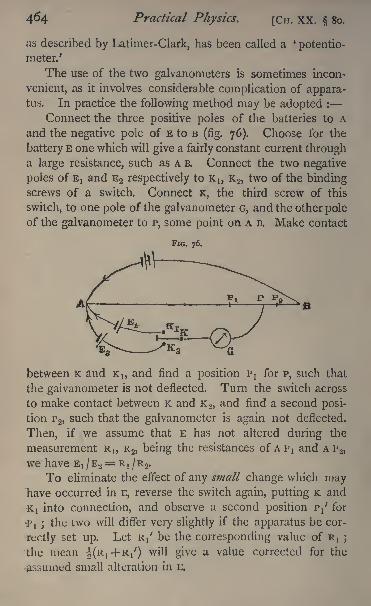
464 Practical Physics. [CH. XX. 80.
as described by Latimer-Clark, has been called a '
potentio-
meter.'
The use of the two galvanometers is sometimes incon-
venient, as it involves considerable complication of appara-tus. In practice the following method may be adopted :
Connect the three positive poles of the batteries to A
and the negative pole of E to B(fig. 76). Choose for the
battery E one which will give a fairly constant current througha large resistance, such as A B. Connect the two negative
poles of E! and E2 respectively to K1} K 2 ,
two of the bindingscrews of a switch. Connect K, the third screw of this
switch, to one pole of the galvanometer G, and the other poleof the galvanometer to P, some point on A B. Make contact
FIG. 76.
between K and K,, and find a position PJ for P, such that
the galvanometer is not deflected. Turn the switch across
to make contact between K and K 2 ,and find a second posi-
tion P 2,such that the galvanometer is again not deflected.
Then, if we assume that E has not altered during the
measurement R1}R 2, being the resistances of A p
tand A P 2,
we have ET /E2
= R} /R 2 .
To eliminate the effect of any small change which mayhave occurred in E, reverse the switch again, putting K and
K! into connection, and observe a second position P/ for
'p, ;the two will differ very slightly if the apparatus be cor-
rectly set up. Let R/ be the corresponding value of R, ;
the mean i(Ri+Ri') will give a value corrected for the
assumed small alteration in E.
CH. XX. So.] Ohm's Law. 465
For the resistance A B a long thin wire is sometimes
used. This is either stretched out straight or coiled in a
screw-thread cut on a cylinder of some insulating material.
Contact is made at p by means of a sliding piece of metal.
If this plan be adopted, it is somewhat difficult to get
sufficient resistance between A and B for very accurate work.
It is preferable, if possible, to use resistance boxes. Since
the resistance A B is to be kept the same throughout the
observations, two boxes are necessary. One of these forms
the portion A p, the other the portion p B, the point P. beingthe junction of the two. Having settled the total resist-
ance A B, plugs are taken out of the two boxes to make upthis total. The required adjustment is then attained by
taking plugs, as may be needed, out of the one box A p,
md putting plugs of the same value into the other box p B,
or vice versa, by putting plugs into A p and removing them
from P B. In this way the total resistance A B remains un-
changed.In order to ascertain if the measurement be possible
with the three given batteries, it is best to begin by makingA P large and noting the direction of the deflexion
;then
make it small;
the deflexion should be in the oppositedirection. If this be the case, a value can be found for the
resistance A P, such that the deflexion will be zero.
Experiment. Compare by means of the last arrangement
given above the E.M.F. of the two given batteries.
Enter results thus :
Battery used for main current, two Daniell cells.
Ex= E.M.F. of a Leclanche.
E3= E.M.F. of a Daniell.
Total resistance of A B, 2,000 ohms.
Rt= 1,370
R2= 1,023
Rt
' = 1,374
H H
466 Practical Physics. [Cn. XXI.
CHAPTER XXL
GALVANOMETRIC MEASUREMENT OF A QUANTITY OF
ELECTRICITY AND OF THE CAPACITY OF A CONDENSER.
WE have seen that if two points be maintained steadily
at different potentials, and connected by a conductor,
a current of electricity flows along the conductor and
will produce a steady deflexion in a galvanometer, if there
be one in the circuit If, however, the difference of
potential between the points be not maintained, the flow
of electricity lasts for an exceedingly short time, sufficient
merely for the equalisation of the potential throughout the
conductor. A quantity of electricity passes through the
galvanometer, but the time of transit is too short to allow
it to be measured as a current in the ordinary way. Theneedle is suddenly deflected from its position of equilibrium,
but swings back again through it directly, and after a few
oscillations, comes to rest in the same position as before ;
and it is necessary for our purpose to obtain from theore-
tical considerations the relation between the quantity of
electricity which has passed through the galvanometer and
the throw of the needle.
On the Relation between the Quantity of Electricity which
passes through a Galvanometer and the Initial Angular
Velocity produced in the Needle.
Let K be the moment of inertia of the needle (p. 144),
and suppose that it begins to move with an angular velocity o>.
Then it is shewn in books on Dynamics, (see also Maxwell,'Matter and Motion/ p. 56), that the moment of momentumof the needle is K o>, and the kinetic energy \ K co
2.
Now, by the second law of motion, the moment of
momentum is equal to the moment of the impulse produced
by the passage of the electricity, and, by the principle of the
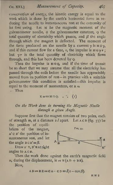
CH. XXI.] Measurement of Capacity. 467
conservation of energy, the kinetic energy is equal to the
work which is done by the earth's horizontal force in re-
ducing the needle to instantaneous rest at the extremity of
its first swing. Let M be the magnetic moment of the
galvanometer needle, G the galvanometer constant, Q the
total quantity of electricity which passes, and j3 the angle
through which the magnet is deflected. The moment of
the force produced on the needle by a current y is M G y,
and if this current flow for a time, T, the impulse is M G y T;
but yr is the total quantity of electricity which flows
through, and this has been denoted by Q.
Thus the impulse is M G Q, and if the time of transit
be so short that we may assume that all the electricity has
passed through the coils before the needle has appreciablymoved from its position of rest in practice with a suitable
galvanometer this condition is satisfied this impulse is
equal to the moment of momentum, or K o>.
Thus
Kw= MGQ. . . (l)
On the Work done in turning the Magnetic Needle
through a given Angle.
Suppose first that the magnet consists of two poles, each
of strength #2, at a distance 2 / apart. Let A c B(fig. 77) be
the position of equili-
brium of the magnet,FrG- ? 7<
A' c B ; the position of in-
stantaneous rest, and let
the angle B c B'=/?.A
Draw A' D, B' E at right
angles to A c B.
Then the work done against the earth's magnetic field
H, during the displacement, is m H (A D + B E).
Now,
A D= B E= C A C D= /( I COSft).
H H 2

468 Practical Physics. [Cn. XXI.
Hence the work done
= 2 ;;//H (i-cos/3).
The whole magnet may be considered as made up of a
series of such magnetic poles, and if we indicate by 3 the
result of the operation of adding together the effects on all
the separate poles, the total work will be
H(I cos /?) 2(2/0 /).
From the definition of the magnetic moment (p. 356],
it can readily be shewn that
M = S (2 m /).
Hence the total work will be
MH(I cos/J).
And this work is equal to the kinetic energy produced
by the impulse, that is to J K o>2
.
So that1 K (O
2= M H (l COSft).
Thus from (i)
"
MGQ-tt- /(2MH(l-COSff)l ,v
K A/ I K
/VHK\vlir>
Thus
^_2sini/?
But if T be the time of a complete oscillation of the
needle, and if we suppose that there is no appreciable
damping, i.e. that the amplitude of any swing of the needle
differs but very slightly in magnitude from that of the pre-
ceding, then since the couple acting on the magnet when
displaced through a small angle is, approximately, M H 0,
Hence substituting for K/M we find from (2)
Cn. XXL] Measurement of Capacity. 469
If the consecutive swings decrease appreciably, then
it follows, from the complete mathematical investigation
(Maxwell, 'Electricity and Magnetism,' 749), that we
must replace sin \ ft in the above formula by (i +^ A) sin ^ ft,
where A is quantity knowrn as the logarithmic decrement,and depends on the ratio of the amplitudes of the con-
secutive vibrations in the following manner :
If clbe the amplitude of the first and <rn that of the
#th vibration when the magnet, after being disturbed, is
allowed to swing freely, then (Maxwell, 'Electricity and
Magnetism,' 736)
i .
A= iofi
n i
Thus we get finally
(4)
We have used the symbol H for the intensity of the
field in which the magnet hangs, though that field need not
necessarily be produced by the action of the earth's mag-netism alone
;we may replace H/G by k, the reduction factor
of the galvanometer under the given conditions. Then,if^be known for the galvanometer used, and T, ft and A
be determined by observation, we have all the quantities
requisite* to determine the quantity of electricity which
has passed through. A galvanometer adapted for such a
measurement is known as a ballistic galvanometer. In
such a one, the time of swing should be long and the
damping small. These requisites are best attained by the
use of a heavy needle, supported by a long torsionless fibre
of silk. For accurate work the deflexions should be ob-
served by the use of a scale and telescope, as described
in 23.
We shall in the following sections describe some experi-
ments in which we require to- use the above formula to
obtain the results desired.
47 Practical PJiysics. [CH. XXI.
On Electrical Accumulators or Condensers.
Consider an insulated conductor in the form of a plate,
which is connected with one pole of a battery ;let the other
pole, suppose for clearness the negative one, be put to
earth, it will be at zero potential. The plate will have a
charge of positive electricity on it depending on its form,
and its potential will be equal to the E.M.F. of the
battery.
Take another plate, connected with the earth, and bring
it into the neighbourhood of the first plate. This second
plate will be at potential zero, and its presence will tend to
lower the potential of the first plate, and thus will producea flow of positive electricity from the battery to the first
plate, sufficient to raise its potential again to that of the
positive pole of the battery. The quantity of electricity
which thus flows in will depend on the form and relative
position of the two plates, and the nature of the insulating
medium which separates them. The flow of electricity will
last but an exceedingly short time; and, if allowed to pass
through a ballistic galvanometer, will produce a sudden
throw of the needle of the nature described on p. 466. If
(3 be the angle through which the needle is deflected, then,
as we have seen, the quantity of electricity which passes is
proportional to sin ^ /?.
It is not necessary to connect the negative pole of the
battery and the second plate of the condenser to earth;
it
will be sufficient if they be in electrical communication with
each other;in either case the difference of potential between
the plates will be equal to the E.M.F. of the battery.
Neither is it necessary that the two plates of the con-
denser should be capable of being separated ;the effects
will be exactly the same if we suppose one plate to be in
connection with the negative pole of the battery, and then
make contact by means of a key between the second plate
and the positive pole. The condenser can be discharged
CH. xxi.j Measurement of Capacity. 471
by putting its two plates in metallic connection by means
of a wire.
Moreover it can be shewn that if there be a quantity Q
of positive electricity on the one plate of the condenser,
there will be a quantity Q on the other. (See Maxwell's'
Elementary Electricity,' p. 72.) By the charge of the con-
denser is meant the quantity of electricity on the positive
plate.
DEFINITION OF THE CAPACITY OF A CONDENSER. It
is found by experiment that the charge required, to pro-
duce a certain difference of potential between the plates
of a condenser bears a constant ratio to the difference of
potential. This constant ratio is called the capacity of the
condenser.
Thus if the charge be Q, the difference of potential
between the plates v, and the capacity c, we have, from the
above definition,
c= -,or Q = c v.
The capacity, as has been said, depends on the geome-trical form of the condenser and the nature of the insulating
medium. If the condenser take the form of two large flat
plates, separated by a short interval, the capacity is ap-
proximately proportional to the area of the plates directly,
and to the distance between them inversely.
Condensers of large capacity are frequently made of a
large number of sheets of tinfoil, separated from each other
by thin sheets of mica. The alternate sheets i, 3, 5, &c.,
are connected together and form one plate ;the other set
of alternate sheets, 2, 4, 6, &c., being connected together to
form the other plate. Sheets of paraffined paper are some-
times used instead of mica.
DEFINITION OF THE UNIT OF CAPACITY. The unit of
capacity is the capacity of a condenser, in which unit charge
produces unit difference of potential between the plates.
472 Practical Physics. [CH. XXI.
The C.G.S. unit thus obtained is, however, found to be
far too great for practical purposes, and for these the ' farad'
has been adopted as the practical unit of capacity. Thefarad is the capacity of a condenser in which a charge of
one coulomb that is, the charge produced by an ampereof current flowing for one second is required to producebetween the plates of the condenser a difference of potential
of i volt.
Since the quantity of electricity conveyed by an amperein one second is lo' 1 C.G.S. units and i volt=io8 C.G.S.
units, we have
i farad= . C.G.S. units.IOX I0b
= io-9 C.G.S. units.
Even this capacity, i farad, is very large, and it is
found more convenient in practice to measure capacities in
terms of the millionth part of a farad or a microfarad.
Thus i microfarad = rrC.G.S. units.io 15
On the Form of Galvanometer suitablefor the Comparison
of Capacities.
The capacities of two condensers are compared most
easily by comparing the quantities of electricity required to
charge them to the same difference of potential, being directly
proportional to these quantities.
Now the quantity of electricity required to charge a con-
denser to a given difference of potential will not depend on
the resistance of the conductor through which the charge
passes. The same total quantity will pass through the wire
whatever be its resistance;the time required to charge the
condenser will be greater if the resistance be greater, but,
even if the resistance be many thousand ohms, the time of
charging will be extremely small.
The effect produced on the galvanometer needle by a
given quantity of electricity will be proportional to the num-
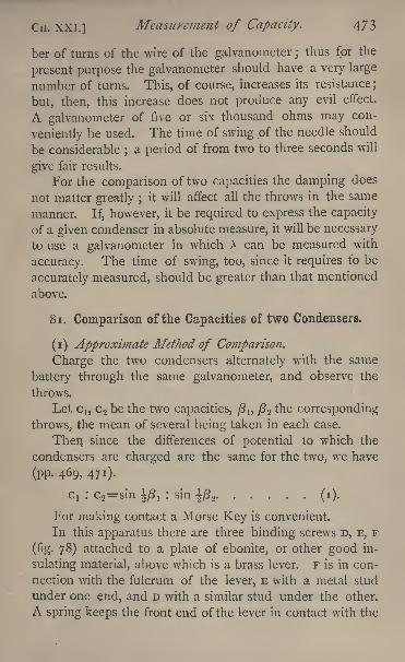
CH. XXL] Measurement of Capacity. 473
her of turns of the \vire of the galvanometer ;thus for the
present purpose the galvanometer should have a very large
number of turns. This, of course, increases its resistance;
but, then, this increase does not produce any evil effect.
A galvanometer of five or six thousand ohms may con-
veniently be used. The time of swing of the needle should
be considerable ;a period of from two to three seconds will
give fair results.
For the comparison of two capacities the damping does
not matter greatly ;it will affect all the throws in the same
manner. If, however, it be required to express the capacity
of a given condenser in absolute measure, it will be necessary
to use a galvanometer in which X can be measured with
accuracy. The time of swing, too, since it requires to be
accurately measured, should be greater than that mentioned
above.
8 1. Comparison of the Capacities of two Condensers.
(i) Approximate Method of Comparison.
Charge the two condensers alternately with the same
battery through the same galvanometer, and observe the
throws.
Let cl5C 2 be the two capacities, ft lt j3 2 the corresponding
throws, the mean of several being taken in each case.
Then since the differences of potential to which the
condensers are charged are the same for the two, we have
(pp. 469, 471).
Cj : c 2=sin |/?! : sin |^2 (0-
For making contact a Morse Key is convenient.
In this apparatus there are three binding screws D, E, F
(fig. 78) attached to a plate of ebonite, or other good in-
sulating material, above which is a brass lever. F is in con-
nection with the fulcrum of the lever, E with a metal stud
under one end, and D with a similar stud under the other.
A spring keeps the front end of the lever in contact with the
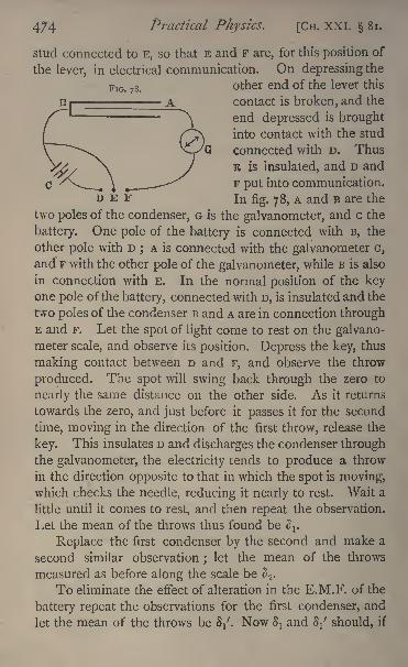
Practical Physics. [CH. XXL 81.
stud connected to E, so that E and F are, for this position of
the lever, in electrical communication. On depressing the
FlG . 78 .other end of the lever this
contact is broken, and the
end depressed is broughtinto contact with the stud
connected with D. Thus
E is insulated, and D and
C '/X.4
--^ F put into communication.
~~~3 E F In fig. 7 8, A and B are the
two poles of the condenser, G is the galvanometer, and c the
battery. One pole of the battery is connected with B, the
other pole with Dj A is connected with the galvanometer G,
and F with the other pole of the galvanometer, while B is also
in connection with E. In the normal position of the keyone pole ofthe battery, connected with D, is insulated and the
two poles of the condenser B and A are in connection throughE and F. Let the spot of light come to rest on the galvano-meter scale, and observe its position. Depress the key, thus
making contact between D and F, and observe the throw
produced. The spot will swing back through the zero to
nearly the same distance on the other side. As it returns
towards the zero, and just before it passes it for the second
time, moving in the direction of the first throw, release the
key. This insulates D and discharges the condenser throughthe galvanometer, the electricity tends to produce a throw
in the direction opposite to that in which the spot is moving,which checks the needle, reducing it nearly to rest. Wait a
little until it comes to rest, and then repeat the observation.
Let the mean of the throws thus found be <^.
Replace the first condenser by the second and make a
second similar observation ; let the mean of the throws
measured as before along the scale be S 2 .
To eliminate the effect of alteration in the E.M.F. of the
battery repeat the observations for the first condenser, and
let the mean of the throws be 8/. Now Sland S/ should, if
CH. XXI. Si.] Measurement of Capacity. 4?$
the battery has been fairly constant, differ extremely little ;
the mean i(t>i +V) should be taken for the throw.
Let D be the distance between the scale and the galvano-
meter mirror. Then, as we have seen ( 71)
S=D tan 2/3
and
so that
. . (2)
And if the ratio 3/D be small we may put ^ for
sm tan-(l)j
(see p. 45).
Hence we find from (i) and (2)
Ci : c2=
$i : S2-
With most condensers a phenomenon known as electric
absorption occurs. The electricity appears to be absorbed
by the insulating medium, and continues to flow in for sometime : it is therefore better, in this case, to put the galvano-meter between E and B. By depressing the key for an
instant the condenser is charged, but in such a way that
only the discharge passes through the galvanometer ; or, if
preferred, the galvanometer can be put between c and D,
and only the charge measured; or, finally, the wires con-
nected to D and E may be interchanged, the galvanometer
being preferably between B and D; when in the normal posi-
tion of the key, the condenser is charged, and a discharge,
sudden or prolonged, is sent through the galvanometer on
depressing the key. By these various arrangements the
effects of alterations in the length of the time of charge or
discharge can be tested. They all have the disadvantagethat there is no ready means of checking the swing of the
needle, and time is taken up in waiting for it to come to
rest.
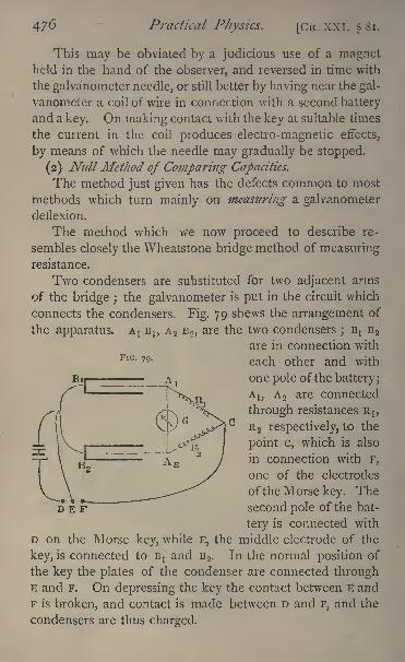
476 Practical Physics. [Cn. XXI. 81,
This may be obviated by a judicious use of a magnetheld in the hand of the observer, and reversed in time with
the galvanometer needle, or still better by having near the gal-
vanometer a coil of wire in connection with a second battery
and a key. On making contact with the key at suitable times
the current in the coil produces electro-magnetic effects,
by means of which the needle may gradually be stopped.
(2) Null Method of Comparing Capacities.
The method just given has the defects common to most
methods which turn mainly on measuring a galvanometerdeflexion.
The method which we now proceed to describe re-
sembles closely the Wheatstone bridge method of measuringresistance.
Two condensers are substituted for two adjacent arms
of the bridge ;the galvanometer is put in the circuit which
connects the condensers. Fig. 79 shews the arrangement of
the apparatus. AJ BI}A 2 B 2 ,
are the two condensers ;E
{B 2
are in connection withFlG - 79> each other and with
one pole of the battery;
A b AO are connected
through resistances R 15
R 2 respectively, to the
point c, which is also
in connection with F,
one of the electrodes
of the Morse key. Thesecond pole of the bat-
tery is connected with
D on the Morse key, while E, the middle electrode of the
key, is connected to BJ and B 2 . In the normal position of
the key the plates of the condenser are connected throughE and F. On depressing the key the contact between E and
F is broken, and contact is made between D and F, and the
condensers are thus charged.
D E F
di. XXI. Si.j Measurement of Capacity. 4/7
In general it will be found that on thus making contact
the galvanometer needle is suddenly deflected. We shall
shew, however, that if the condition CiRj = C 2 R 2 hold,
c,, C 2 being the two capacities, there will not be any current
through the galvanometer, the needle will be undisturbed
(see below). To compare the two capacities, then, the re-
sistances R! R2 must be adjusted until there is no effect
produced in the galvanometer, by making or breaking
contact, and when this is the case we have
and R,, R 2 being known, we obtain the ratio c,/c2 . In per-
forming the experiment it is best to choose some large
integral value, say 2000 ohms for Rl5 and adjust R 2 only.
We proceed to establish the formula
G! R1=c2 R2 .
No current will flow from AIto A 2 if the potential of
these two points be always the same. Let v be the con-
stant potential of the pole of the battery in contact with
BJ and BO, Y! that of the other pole. Let v be the common
potential of ALand A 2 at any moment during the charging,
and consider the electricity which flows into the two
condensers during a very short interval T. The poten-tial at c is v 1} and at A
Iand A 2 it is v at the beginning of
the interval. The current along c A! will be then (v t V)/R I}
and along c A 2 , (v, v)/R 2 ;and if the time T be sufficiently
small, the quantity which flows into the two condensers
will be respectively (V I V)T/R Iand (YJ v)r/R 2 . The
inflow of this electricity will produce an increase in the
potential of the plates AJ and A 2 ;and since, if one plate of
a condenser be at a constant potential, the change in the
potential of the other plate is equal to the increase of the
charge divided by the capacity, we have for the increase of
the potential at Atand A 2 during the interval T, when T is very
small, the expressions (v l V)T/C,R Iand (Vj v)r/c 2
R 2
respectively.
4/8 Practical Physics. [CH. XXI. 81.
By the hypothesis Aland A 2 are at the same potential
at the beginning of the interval T, if the two expressions
just found for the increment of the two potentials be equal,then the plates will be at the same potential throughout the
interval.
The condition required is
CT R! C2 R2
and this clearly reduces to
C1R
1=C2 R 2 .
Thus, if G! R! = c2 R 2 the plates AJ, A 2 will always be
at the same potential, and in consequence no effect will be
produced on the galvanometer.The complete discussion of the problem (' Philosophical
Magazine,' May 1881) shews that the total quantity of
electricity which flows through the galvanometer during the
charging is
(V,-V )(R 1C
1-R 2 C 2)/(G+ R
1 + R 2)
where G is the resistance of the galvanometer. It follows
also that the error in the result, when using a given galva-
nometer, will be least when the resistances RJ and R 2 are as
large as possible ;and that if we have a galvanometer with
a given channel, and wish to fill the channel with wire so
that the galvanometer may be most sensitive, we should make
G = R1 +R2 .
The effects of electric absorption sometimes produce
difficulty when great accuracy is being aimed at. They maybe partially avoided by making contact only for a very short
interval of time. For a fuller discussion of the sources
of error reference may be made to the paper mentioned
above.
Experiments. Compare the capacities of the two con-
densers, (i) approximatively ; (2) by the null method last de-
scribed.
CH. XXI. 81.] Measurement of Capacity. 479
Enter results thus :
Condensers A and B.
(i) ^ (mean of 3 observations) 223 scale divisions.
2 (mean of 6 observations) 156
S/ (mean of 3 observations) 225
.".SL--S-I-44.c2 156
(2) R!= 2000 ohms.
L-- 1-437.C2
2000
82. Measurement of the Capacity of a Condenser.
The methods just described enable us to compare the
capacities of two condensers that is, to determine the capa-
city of one in terms of that of a standard ; just as Poggen-dorffs method ( 80) enables us to determine the E.M.F. of
a battery in terms of that of a standard. We have seen,
however, in section 74 how to express in absolute measure
the E.M.F. between two points ;we proceed to describe how
to express in absolute measure the capacity of a condenser.
Charge the condenser with a battery of E.M.F., E througha galvanometer, and let /3 be the throw of the needle, k the
reduction factor of the galvanometer, T the time of swing,X the logarithmic decrement, c the capacity of the condenser,and Q the quantity in the charge.
Then
7T E
by formula (4) of p. 469.
Shunt the galvanometer with i/( i)th of its own re-
sistance G, so that i /nth only of the current passes throughthe galvanometer ;
let B be the resistance of the battery ; passa current from the battery through a large resistance R and
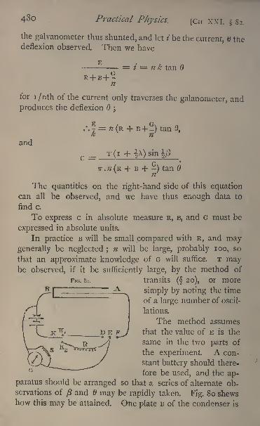
480 Practical Physics. [CH XXI. 82.
the galvanometer thus shunted, and let / be the current, trie
deflexion observed. Then we have
1? = * = n k tan d
for i /nth of the current only traverses the galanometer, and
produces the deflexion ;
tanO,
and
sm
Fir;. So.
TT.W(R + B + -) tan
The quantities on the right-hand side of this equationcan all be observed, and we have thus enough data to
find c.
To express c in absolute measure R, B, and G must be
expressed in absolute units.
In practice B will be small compared with R, and maygenerally be neglected ;
n will be large, probably 100, so
that an approximate knowledge of G will suffice. T maybe observed, if it be sufficiently large, by the method of
transits( 20), or more
simply by noting the time
of a large number of oscil-
lations.
The method assumes
that the value of E is the
same in the two parts of
the experiment. A con-
stant battery should there-
fore be used, and the ap-
paratus should be arranged so that a series of alternate ob-
servations of /? and d may be rapidly taken. Fig. 80 shewshow this may be attained. One plate B of the condenser is
Cn. XXI. 82.] Galvanomctric Measurement. 481
connected to one pole of the battery and to the galva-
nometer;the other plate A is connected to the electrode
F of the Morse key. The other pole of the galvanometeris connected to the electrode E, so that in the normal
position of the key the two plates are in connection throughthe galvanometer and the key E F.
The second pole of the battery is connected to one
electrode K of a switch, and the electrode D of the Morse
key is connected with another electrode KJ of the switch.
The centre electrode E of the key is connected through the
resistance R to the third electrode K 2 of the switch, s is
the shunt. With the switch in one position contact is madebetween K and KJ ;
on depressing the key the condenser is
charged, the galvanometer being out of circuit, and on
releasing the key the condenser is discharged through the
galvanometer. Note the zero point and the extremity of
the throw, and thus obtain a value S for the throw, in scale
divisions.
Shunt the galvanometer, and move the switch connec-
tion across to K.2 . A steady current runs through the re-
sistance R and the shunted galvanometer ;let the deflexion
in scale divisions be d;reverse the connections, and repeat
the observations several times. The damping apparatusdescribed in the previous section will be found of use. Bymeasuring approximately the distance D between the scale
and needle we can find tan and sin -?5 /3 in terms of d andS. An approximate value only is required of D from the
same reasons as in 71.
Experiment. Determine absolutely the capacity of the
given condenser.
Enter the results thus :
D = 1230 scale divisions.
=254-5 mean of 4 observations.
n
Whence ll -= 2 55 '-35
e/ = 6 6'-i.
i i
482 Practical Physics. [Cn. XXI. 82.
Observations for X :
= I5J ^ = 220; 4, = 60;# = io; ^ = 210; cn = 94.
Mean value of X -091.
Observations for T :
20 double vibrations take 64-5 seconds (same value for each of
three observations).T = 3*225 seconds;
R = 5000 ohms =5 x io12 C.G.S units
;
= 5600 =5'6 x io12 C.G.S. units
;
Battery I Daniell cell of negligible resistance
n = 100.
Whence C = roi2 microfarad.
INDEX.
ADS
A BSORPTION, electric, 475-ex of light, measurement of, 342Acceleration due to gravity, method of
measuring, 128, 136Accumulator, 470Acoustics, definitions, &c., 164Air lines, spectrum of, 302
thermometer, 208
Alluard, modification of Regnault's hy-grometer, 242
Ampere, definition of, 391Angle of a wedge of glass, measurement
of, 292of incidence of light on a reflecting
surface, 314of prism, method of measuring, 308
Angles, measurement of, 80
Approximation, 41
Aqueous vapour, chemical determinationof density of, 233
, tension of, 231Areas, measurement of, 73Arithmetical manipulation, 36Arms of a balance, 100
Aspirator, 234Astatic magnets, 402Atwood's machine, 133
B.A.wire bridge, 451
, Fleming's form of, 459Balance, adjustment of, 87
, hydrostatic, 107, Jolly's, 120
,sensitiveness of the, 84, 97
, testing adjustments of a, 98, theory of the, 83
Ballistic galvanometer, 469, 472Barometer, aneroid, 157
, comparison of aneroid and mercury,158
,correction of readings, 155
, measurement of height by the, 159, mercury, 153
Base line, measurement of, 64Battery resistance, Mance's method,447
CORBeam compass, 54Beats, 165Binomial theorem, 42
! Bi-prism, 319
j
Bi-quartz, 327I
, method of determining plane of po-larisation by aid of, 328
Bird-call, 181
Boiling point, determination of, 193,of a liquid, 196
Borda's method of weighing, 101
Boyle's law, 160
Bridge-wire, calibration of a, 460Bunsen's photometer, 244Buoyancy of air, correction of weighings
for, 103Burette, 79
CALIBRATIONof a tube, 75
Calipers, 50Calorimeter, description of, 214Calorimetry, 211
Capacities, comparison of electrical, 473,Null method of comparing, 476
Capacity, absolute measurement of, 479, definition of electrical, 471, unit of electrical, 471
Carey Foster's method of comparing re-
sistances, 455Clifford, 4Colour box, 345
top, 337vision, 337
, Lord Rayleigh's observations on,340
Commutator, 408Comparison of spectra, 301Compressibility, 139Concave mirror, focal length of, 261
Condenser, definition of capacity of, 471Condensers, 470Conductivity, 421Cooling, method of, 225Cornu's prism, 334Corrections, arithmetical calculation of,
39
Index.
CUR
Current, absolute measure of a, 391of electricity, 386
DALTON'S experiment, 228
law, 231Damping, correction for, 469Density, definition of, 105
, determination of, by the volumeno-meter, 163
Deviation, position of minimum, 311Dew point, 233, determination of, 239, 241
Diffraction experiments, 324grating, 315
Dimensional equations, 24, 27Dines's hygrometer, 238Division, abbreviated form of, 38Double weighing, 100
Drying, method of, 112
tubes, 234
EARTH'S magnetic force, measure-ment of, 373, 375
Elasticity, theory of, 139Electric battery, 385
current, 385field, 381
Electrical decomposition of water, 411force, definition of, 382phenomena, 381potential, definition of, 383quantity, 381resistance, absolute unit of, 425
, definition of, 421measured by Wheatstone's bridge,
443
Electricity, conductors of, 382, definitions and explanation of terms,
Electro-chemical equivalents, 406, comparison of, 411
Electrodes, 406Electrolysis, 406Electro-magnetic unit current, definition
of, 388Electromotive force, definition of, 383
measurement of, 416forces, methods of comparing, 435
compared by equal deflexion
method, 436compared by equal resistance
method, 436, PoggendorfTs method of com-
paring, 461Equipotential surfaces, 351Error, Mean, 34Error, Probable, 34Errors, 31
calculation of effect of hypothetical
, special sources of, 48
Ether vapour, pressure of, 230Expansion, 183
, coefficient of, 198, measurement of, 199
by a weight thermometer, 202of water, measurement of, 192
Extrapolation, 189
FARADAY'Slaw ofelectrolysis, 406
Fluid pressure, measurement of, 152Focal lengths of lenses, 267
Focal lines, 276, 291Focussing for parallel rays, 281
Force, gravitation measure of, 12
Freezing point, determination of, 193Frequency of a note, 165Fresnel's mirrors, 323Fusing point of a solid, 197
f~^ ALVANOMETER, 389, 395V-J adjustment of a, 404
adjustment of reflecting, 391, ballistic, 469, best arrangement for a tangent, 47, control magnet of a, 401, 403, 404, de:ermination of reduction factor ofa
i 45, Helmholtz form, 400, reduction factor of, 401Delation between current and deflexionof a, 405, sensitiveness of a, 402, shunting a, 424constant, definition of, 397deflexion measured by reflexion of a
spot of light, 392deflexions, methods of reading, 398for comparison of capacities, 472for_strong currents, 401resistance, Thomson's method, 445
Gas flame, sensitive, 181
Gas-meter, 245Glass tubes, methods of drying, 75
HARMONICS, 165Heat, quantities of, 211
, units of, 211
generated by a current, 416Height, measurement by the barometer,
159--, measurement of, by hypsometer, 195Homogeneous light,method ofobtaining,
Horizon, artificial, 258Humidity, relative, 232Hydrometer, common, 123
, Nicholson's, 117Hygrometer, Dines's, 238
, Regnault's, 241
Index. 485
IIYG
Hygrometry, 231
Hypsometer, 193, 195
IMPULSE due to passage of a quan-i tity of electricity, 467Index of refraction, definition of, 302
,measurement of, with a micro-
scope, 303with a spectrometer, 309
Induction coil, spectrum of spark of an,
299Inertia, moment of, 144
Interpolation, 41
Ions, 406
T ELLETT'S pri,m, 334J Jolly's air thermometer, 208
Jolly's balance, 120
Joule's law, 416
T/^ATHETOMETER,66 ; 125-LX. Kilogramme standard, n
LATENTheat of steam, 221
of water, 219Latimer-Clark's potentiometer, 463Laurent's method of measuring position
of plane of polarisation, 335Legal ohm, 426Length, apparatus for measuring, 50,
54) 57> 59. 64Lens, focal length of a long focussed,
293, magnifying power of, 283
Lenses, measurement of focal lengths of,
267, &c.
Leyden jar, used with spectroscope and
coil, 299Lippich's method of measuring positionof plane of polarisation, 334
Liquid, measurement of refractive index
of, 304, 312Logarithmic decrement, 469, 479Lupton, 30
MAGNETand mirror, 391
Magnetic axis, 348declination, measurement of, 375field, 350
due to a current, 387, exploration of a, 379measurement of strength of, 373
force, laws of, 349,line of, 350
, measurement of, 364, 373due to a current, verificatic
law of, 394forces on a magnet, 355, 359induction, 366
PAR
Magnetic meridian, 348moment, 356
,measurement of, 366, 370, 373,
375poles, 348
;;p ten
.
tia1.'SSL 353,353
Magnetisation by divided touch, 369of a steel bar, 367
Magnetism, definitions and explanationsconcerning, 348, c.
Magnets, experiments with, 367, properties of, 347
Magnifying power of a telescope, 279of a microscope, 283of a lens, 283
powers of optical instruments, 278Mapping a spectrum, 297Maxwell's theory of colour, 338
vibration needle, 146Mean of observations, 32, 34, 35Measurement, methods of, 2, 5
, units of, 9Measurements, approximate, 30
, possible accuracy of, 35
Mercury, filling a barometer tube vith,228
Method of mixture, 212
Metre, standard, nM icroscope, magnifying power of, 283
used to measure refractive indices, 303Microscopes, travelling, 64
used to measure expansion, 200Mirror telescope and scale, method of
adjusting, 147Moment of inertia, 144
,determination of, 145, 150
Monochord, 175Morse key, 473, 481
Multiplication, abbreviated form of, 38
39Musical note, 164
N ICOL'S prism, 325--, adjustments of, 326
Distance, 42 =OHM, legal, 426pract cal unit of resis
Ohm's law, 420Optical bench, 318
measurements, general method for
some, 259Oscillation, method of observing time of,
128
Oscillations, method of comparing times
of, 132
,of weighing by, 91, 97
PARALLAX, method of avoidingI error due to, 194Parallax, optical adjustment h*' means
of, 251, 262, 271
486 Index.
PAR
Parallel rays, focussing for, 281Partial tones, 1^5Pendulum, 128
Photometer, Bunsen's, 244, Rumford's, 248
Photometry, theory of, 243Physical constants, tables of, 30
laws, quantitative, 13quantities, 2
Pitch, absolute, 175of tuning forks, comparison of, 165
Plane surface to set a in a givenposition, 307surfaces, optical tests for, 287
Planimeter, 74Polarimeters, shadow, 332Polarisation, determination of plane of,
325
, measurement of position ofplane of,
, rotation of plane of, 325Polarised light, 325Polarising apparatus, 325Potential, electrical, 383
,zero of, 385due to a magnet, 358of the earth, 384
Potentiometer, 461Pound standard, nPoynting's method of measuring the
position of the plane of polarisation,
336Pressure, measurement of fluid, 152Principal points of a lens, 270, 273Prism, adjusting a, 297
, adjustment of, on a spectrometer,37,measurement of angle of, 308
,measurement of refractive index of,
309Pumice stone, 234
QUANTITY,numerical measure of,
13of electricity, galvanometric measure-ment of, 466
RADIUSof curvature, optical mea-
surement ol, 261, 263, 290Reflexion, radius of curvature measured
by, 290or light, verification of law of, 250, 308
Refractive index, definition of, 302
,measurement of, 309
Regnault, experiments on Dalton's law,
231Regnault's hygrometer, 241
Resistance, comparison of, 430, definition of electrical, 421
,measurement of battery, 433, 447
STR
Resistance, measurement of galvano-meter, 433, 445
, relation between temperature and,429, 458
, work and, 421, specific, 429, standards of, 421boxes, 427measured by B.A. wire bridge, 451of conductors in multiple arc, 423
in series, 422mercury 426
Resistances compared by Carey Foster's
method, 455Resonance tube, 172Resonator, 165
Rigidity, 139Rumford's photometer, 248
OCALE pans, comparison of weightsO of, loi
telescope and mirror, method of ad-justing, 147
Screw-gauge, 57Sensitiveness of a balance, 91, 97, 99Sextant, adjustments of, 254 ^Shearing strain, 139Shunts, 424Sine galvanometer, 389, 397Siren, 168
, method of using, 170Solenoidal magnet, 348, 356, 358, 359
,force due to a, 359
Sound, velocity of, 172Specific gravity, definition of, 105
bottle, 112
of a liquid, methods of measuring,in, 116, 118, 123, 132
of a solid, methods of measuring,107, 109, 112, 116, 117, 121, 163heat, definition of, 212
, method of cooling, 225,
'
of mixture, 212of a liquid, 218
resistance, 429, measurement of, 453
Spectra, comparison of, 301Spectro-photometer, 244, 341Spectrometer, 305
, adjustment of, 306Spectroscope, 297
, adjustment of a, 297Spectrum, mapping a, 297--, method of obtaining a pure, 296
, pure, 295of electric spark, 299
Spherometer, 59Standards office of Board of Trade, 2, nStrain, 139Strengths of absorbing solutions, com-
parison of, 344Stress, 130
String*, vibration of, 175
Index. 487
TAB
TABLES,use of, 40
Tangent galvanometer, 389, 397
Tap, three-way, 113
Taring, lot
Telescope, magnifying powers of, 279,281
mirrorand scale, method of adjusting,
147Temperature, definition cf, 183
,measurement of high, 189method of measuring, 183, 185and resistance, determination of re-
lation between, 458Thermometer, air, 208
centigrade, 185construction of a, 190corrections of, 186
Fahrenheit, 185Kew corrections, 187, 188
standard, 187mercury, 184testing a, 193the weight, 202wet and dry bulb, 238
Thermometry, 183Time, measurement of, 80
ofoscillation, method ofobserving, 128
Torsion, determination of modulus of,
146,modulus of, 139, 140, 144
Trigonometrical approximations, 45
Tuning forks, comparison of pitch of, 165
UNITof heat, anof resistance, British Associa-
tion, 426Units, absolute, 17
, arbitrary and absolute, 10
, change of, 24, 28
, derived, 17
YOU
Units, fundamental, 17
, practical electrical, 22
,table of arbitrary, 23
,the C.G.S. system of, 21
VELOCITYof sound, 172
Verniers, 50, 53
Vibration, method of observing time of
complete, 148frequency, determination of, 168
needle, Maxwell's, 146number, 164of strings, 175
Volt, practical unit of E.M.F., 419
Voltameter, 406, 408, 410as a current meter, 409for decomposing water, 411
Volume, measurement of, 78
Volumenometer, 160
WATCH, rating a, 81
Water; electrical decompositionof, 411, expansion of, 192equivalent, 213
,determination of, 216
Wave length, measurement of, 315, 319
, by spectrometer, 298of a high note, 180
Weighing, method ofdouble,
101
oscillations, 91, 97
Weight thermometer, 202
Weights, 91, 97Wheatstone Bridge, theory of. 437
\TARDstandard, n
Young's modulus, 140, 141
PRINTED BY
SJ'OTTISWOODE AND CO., NEW-STREET SQUARE
LONDON
UNIVERSITY OF TORONTO
LIBRARY
Do not
re move
the card
from this
Pocket.
Acme Library Card Pocket
Under Pat." Ref . Index File."
Made by LIBRARY BUREAU