Nonlinear Fuzzy Model-base Technique to Compensate Highly Nonlinear Continuum Robot Manipulator
14
I.J. Intelligent Systems and Applications, 2013, 12, 135-148 Published Online November 2013 in MECS (http://www.mecs-press.org/) DOI: 10.5815/ijisa.2013.12.12 Copyright © 2013 MECS I.J. Intelligent Systems and Applications, 2013, 12, 135-148 Nonlinear Fuzzy Model-base Technique to Compensate Highly Nonlinear Continuum Robot Manipulator Farzin Piltan Senior Researcher at Research and Development Unit, Sanatkadehe Sabze Pasargad Company, (S.S.P. Co), Shiraz, Iran E-mail: [email protected] Mehdi Eram Research and Development Unit, Sanatkadehe Sabze Pasargad Company, (S.S.P. Co), Shiraz, Iran E-mail: [email protected] Mohammad Taghavi Research and Development Unit, Sanatkadehe Sabze Pasargad Company, (S.S.P. Co), Shiraz, Iran E-mail: [email protected] Omid Reza Sadrnia Research and Development Unit, Sanatkadehe Sabze Pasargad Company, (S.S.P. Co), Shiraz, Iran E-mail: [email protected] Mahdi Jafari Research and Development Unit, Sanatkadehe Sabze Pasargad Company, (S.S.P. Co), Shiraz, Iran E-mail: [email protected] Abstract— Refer to this research, a gradient descent optimization methodology for position fuzzy- model based computed torque controller (GDFCTC) is proposed for highly nonlinear continuum robot manipulator. The main problem of the pure computed torque controller (CTC) was equivalent problem in uncertain systems. The simulation results exhibit that the CTC works well in certain system. To eliminate the continuum robot manipulator system’s dynamic; Mamdani fuzzy inference system is design and applied to CTC. This methodology is based on applied fuzzy logic in equivalent nonlinear dynamic part to estimate unknown parameters. This relatively controller is more plausible to implement in an actual real-time when compared to other techniques of nonlinear controller methodology of continuum arms. Based on the gradient descent optimization method, the PD-gain updating factor has been developed in certain and partly uncertain continuum robots. The new techniques proposed and methodologies adopted in this paper supported by MATLAB/SIMULINK results represent a significant contribution to the field of design an optimized nonlinear computed torque controller for continuum robots. Index Terms— Gradient Descent Optimization Algorithm, Computed Torque Methodology, Fuzzy Computed Torque Algorithm, Continuum Robot, Fuzzy Logic Methodology I. Introduction Continuum robots represent a class of robots that have a biologically inspired form characterized by flexible backbones and high degrees-of-freedom structures [1]. The idea of creating “trunk and tentacle” robots, (in recent years termed continuum robots [1]), is not new [2]. Inspired by the bodies of animals such as snakes [3], the arms of octopi [4], and the trunks of elephants [5], [6], researchers have been building prototypes for many years. A key motivation in this research has been to reproduce in robots some of the special qualities of the biological counterparts. This includes the ability to “slither” into tight and congested spaces, and (of particular interest in this work) the ability to grasp and manipulate a wide range of objects, via the use of “whole arm manipulation” i.e. wrapping their bodies around objects, conforming to their shape profiles. Hence, these robots have potential applications in whole arm grasping and manipulation in unstructured environments such as rescue operations. Theoretically,
Transcript of Nonlinear Fuzzy Model-base Technique to Compensate Highly Nonlinear Continuum Robot Manipulator

I.J. Intelligent Systems and Applications, 2013, 12, 135-148 Published Online November 2013 in MECS (http://www.mecs-press.org/)
DOI: 10.5815/ijisa.2013.12.12
Copyright © 2013 MECS I.J. Intelligent Systems and Applications, 2013, 12, 135-148
Nonlinear Fuzzy Model-base Technique to
Compensate Highly Nonlinear Continuum Robot
Manipulator
Farzin Piltan
Senior Researcher at Research and Development Unit, Sanatkadehe Sabze Pasargad Company, (S.S.P. Co), Shiraz, Iran
E-mail: [email protected]
Mehdi Eram
Research and Development Unit, Sanatkadehe Sabze Pasargad Company, (S.S.P. Co), Shiraz, Iran
E-mail: [email protected]
Mohammad Taghavi
Research and Development Unit, Sanatkadehe Sabze Pasargad Company, (S.S.P. Co), Shiraz, Iran
E-mail: [email protected]
Omid Reza Sadrnia
Research and Development Unit, Sanatkadehe Sabze Pasargad Company, (S.S.P. Co), Shiraz, Iran
E-mail: [email protected]
Mahdi Jafari
Research and Development Unit, Sanatkadehe Sabze Pasargad Company, (S.S.P. Co), Shiraz, Iran
E-mail: [email protected]
Abstract— Refer to this research, a gradient descent
optimization methodology for position fuzzy- model
based computed torque controller (GDFCTC) is
proposed for highly nonlinear continuum robot
manipulator. The main problem of the pure computed
torque controller (CTC) was equivalent problem in
uncertain systems. The simulation results exhibit that
the CTC works well in certain system. To eliminate the
continuum robot manipulator system’s dynamic;
Mamdani fuzzy inference system is design and applied
to CTC. This methodology is based on applied fuzzy
logic in equivalent nonlinear dynamic part to estimate
unknown parameters. This relatively controller is more
plausible to implement in an actual real-time when
compared to other techniques of nonlinear controller
methodology of continuum arms. Based on the gradient
descent optimization method, the PD-gain updating
factor has been developed in certain and partly
uncertain continuum robots. The new techniques
proposed and methodologies adopted in this paper
supported by MATLAB/SIMULINK results represent a
significant contribution to the field of design an
optimized nonlinear computed torque controller for
continuum robots.
Index Terms— Gradient Descent Optimization
Algorithm, Computed Torque Methodology, Fuzzy
Computed Torque Algorithm, Continuum Robot, Fuzzy
Logic Methodology
I. Introduction
Continuum robots represent a class of robots that
have a biologically inspired form characterized by
flexible backbones and high degrees-of-freedom
structures [1]. The idea of creating “trunk and tentacle”
robots, (in recent years termed continuum robots [1]), is
not new [2]. Inspired by the bodies of animals such as
snakes [3], the arms of octopi [4], and the trunks of
elephants [5], [6], researchers have been building
prototypes for many years. A key motivation in this
research has been to reproduce in robots some of the
special qualities of the biological counterparts. This
includes the ability to “slither” into tight and congested
spaces, and (of particular interest in this work) the
ability to grasp and manipulate a wide range of objects,
via the use of “whole arm manipulation” i.e. wrapping
their bodies around objects, conforming to their shape
profiles. Hence, these robots have potential applications
in whole arm grasping and manipulation in unstructured
environments such as rescue operations. Theoretically,

136 Nonlinear Fuzzy Model-base Technique to Compensate Highly Nonlinear Continuum Robot Manipulator
Copyright © 2013 MECS I.J. Intelligent Systems and Applications, 2013, 12, 135-148
the compliant nature of a continuum robot provides
infinite degrees of freedom to these devices. However,
there is a limitation set by the practical inability to
incorporate infinite actuators in the device. Most of
these robots are consequently underactuated (in terms of
numbers of independent actuators) with respect to their
anticipated tasks. In other words they must achieve a
wide range of configurations with relatively few control
inputs. This is partly due to the desire to keep the body
structures (which, unlike in conventional rigid-link
manipulators or fingers, are required to directly contact
the environment) “clean and soft”, but also to exploit
the extra control authority available due to the
continuum contact conditions with a minimum number
of actuators. For example, the Octarm VI continuum
manipulator, discussed frequently in this paper, has nine
independent actuated degrees-of-freedom with only
three sections. Continuum manipulators differ
fundamentally from rigid-link and hyper-redundant
robots by having an unconventional structure that lacks
links and joints. Hence, standard techniques like the
Denavit-Hartenberg (D-H) algorithm cannot be directly
applied for developing continuum arm kinematics.
Moreover, the design of each continuum arm varies
with respect to the flexible backbone present in the
system, the positioning, type and number of actuators.
The constraints imposed by these factors make the set
of reachable configurations and nature of movements
unique to every continuum robot. This makes it difficult
to formulate generalized kinematic or dynamic models
for continuum robot hardware. Chirikjian and Burdick
were the first to introduce a method for modeling the
kinematics of a continuum structure by representing the
curve-shaping function using modal functions [6].
Mochiyama used the Serret- Frenet formulae to develop
kinematics of hyper-degrees of freedom continuum
manipulators [5]. For details on the previously
developed and more manipulator-specific kinematics of
the Rice/Clemson “Elephant trunk” manipulator, see [1],
[2], [5]. For the Air Octor and Octarm continuum robots,
more general forward and inverse kinematics have been
developed by incorporating the transformations of each
section of the manipulator (using D-H parameters of an
equivalent virtual rigid link robot) and expressing those
in terms of the continuum manipulator section
parameters [4]. The net result of the work in [6], [3]-[5]
is the establishment of a general set of kinematic
algorithms for continuum robots. Thus, the kinematics
(i.e. geometry based modeling) of a quite general set of
prototypes of continuum manipulators has been
developed and basic control strategies now exist based
on these. The development of analytical models to
analyze continuum arm dynamics (i.e. physicsbased
models involving forces in addition to geometry) is an
active, ongoing research topic in this field. From a
practical perspective, the modeling approaches
currently available in the literature prove to be very
complicated and a dynamic model which could be
conveniently implemented in an actual device’s real-
time controller has not been developed yet. The absence
of a computationally tractable dynamic model for these
robots also prevents the study of interaction of external
forces and the impact of collisions on these continuum
structures. This impedes the study and ultimate usage of
continuum robots in various practical applications like
grasping and manipulation, where impulsive dynamics
[1], [4] are important factors. Although continuum
robotics is an interesting subclass of robotics with
promising applications for the future, from the current
state of the literature, this field is still in its stages of
inception.
Controller is a device which can sense information
from linear or nonlinear system (e.g., continuum robot)
to improve the systems performance [7-9]. The main
targets in designing control systems are stability, good
disturbance rejection, and small tracking error[7-12].
Several continuum robot are controlled by linear
methodologies (e.g., Proportional-Derivative (PD)
controller, Proportional- Integral (PI) controller or
Proportional- Integral-Derivative (PID) controller), but
when robot works with various payloads and have
uncertainty in dynamic models this technique has
limitations. In some applications continuum robot are
used in an unknown and unstructured environment,
therefore strong mathematical tools used in new control
methodologies to design nonlinear robust controller
with an acceptable performance (e.g., minimum error,
good trajectory, disturbance rejection) [8-10].
Computed torque controller (CTC) is a powerful
nonlinear controller which it widely used in control of
robot manipulator. It is based on feedback linearization
and computes the required arm torques using the
nonlinear feedback control law. This controller works
very well when all dynamic and physical parameters are
known but when the robot manipulator has variation in
dynamic parameters, in this situation the controller has
no acceptable performance[7-14]. In practice, most of
physical systems (e.g., robot manipulators) parameters
are unknown or time variant, therefore, computed
torque like controller used to compensate dynamic
equation of robot manipulator[1, 6]. Research on
computed torque controller is significantly growing on
robot manipulator application which has been reported
in [1, 6, 15-20]. Vivas and Mosquera [19]have proposed
a predictive functional controller and compare to
computed torque controller for tracking response in
uncertain environment. However both controllers have
been used in feedback linearization, but predictive
strategy gives better result as a performance. A
computed torque control with non parametric regression
models have been presented for a robot arm[16]. This
controller also has been problem in uncertain dynamic
models. Based on [7- 11, 20-44]and [12-20] computed
torque controller is a significant nonlinear controller to
certain systems which it is based on feedback
linearization and computes the required arm torques
using the nonlinear feedback control law. When all
dynamic and physical parameters are known, computed
torque controller works fantastically; practically a large

Nonlinear Fuzzy Model-base Technique to Compensate Highly Nonlinear Continuum Robot Manipulator 137
Copyright © 2013 MECS I.J. Intelligent Systems and Applications, 2013, 12, 135-148
amount of systems have uncertainties, therefore sliding
mode controller is one of the best case to solve this
challenge.
Gradient descent is a first-order optimization
algorithm. Gradient descent works in spaces of any
number of dimensions, even in infinite-dimensional
ones. In the latter case the search space is typically a
function space, and one calculates the Gâteaux
derivative of the functional to be minimized to
determine the descent direction. The gradient descent
can take much iteration to compute a local minimum
with a required accuracy, if the curvature in different
directions is very different for the given function. To
improve the output performance as well as resolve the
PD gain updating factor this method is used. The PD
gain updating factor of this controller is adjusted off
line depending on the iterations.
This paper is organized as follows; section 2, is
served as an introduction to the computed torque
controller formulation algorithm and its application to
control of continuum robot and dynamic of continuum
robot. Part 3, introduces and describes the methodology
(gradient descent optimal computed torque controller)
algorithm. Section 4 is presented the simulation results
and discussion and the final section is describing the
conclusion.
II. Theory
A. Dynamic Formulation of Continuum Robot
The Continuum section analytical model developed
here consists of three modules stacked together in series.
In general, the model will be a more precise replication
of the behavior of a continuum arm with a greater of
modules included in series. However, we will show that
three modules effectively represent the dynamic
behavior of the hardware, so more complex models are
not motivated. Thus, the constant curvature bend
exhibited by the section is incorporated inherently
within the model. The mass of the arm is modeled as
being concentrated at three points whose co-ordinates
referenced with respect to (see Figure 1);
Where;
- Length of the rigid rod connecting the two struts,
constant throughout the structure
, - Spring constant of actuator at
module
, - Spring constant of actuator at
module
, - Damping coefficient of actuator at
module
, - Damping coefficient of actuator at
module
, - Mass in each module
- Moment of inertia of the rigid rod in
each module.
Fig. 1: Assumed structure for analytical model of a section of a
continuum arm
A global inertial frame (N) located at the base of the
arm are given below
(1)
( ) (2)
( ( ))
( ( )))
(3)
The position vector of each mass is initially defined
in a frame local to the module in which it is present.
These local frames are located at the base of each
module and oriented along the direction of variation of
coordinate of that module. The positioning of each
of these masses is at the centre of mass of the rigid rods
connecting the two actuators. Differentiating the
position vectors we obtain the linear velocities of the
masses. The kinetic energy (T) of the system comprises
the sum of linear kinetic energy terms (constructed
using the above velocities) and rotational kinetic energy
terms due to rotation of the rigid rod connecting the two
actuators, and is given below as

138 Nonlinear Fuzzy Model-base Technique to Compensate Highly Nonlinear Continuum Robot Manipulator
Copyright © 2013 MECS I.J. Intelligent Systems and Applications, 2013, 12, 135-148
The potential energy (P) of the system comprises the
sum of the gravitational potential energy and the spring
potential energy. A small angle assumption is made
throughout the derivation. This allows us to directly
express the displacement of springs and the velocities
associated with dampers in terms of system generalized
coordinates.
( ) ( ( ))
( ) ( ( ) )
( ) ( ( ⁄ ) )
( ) ( ( ⁄ ) )
( ) ( ( ⁄ ) )
( ) ( ( ⁄ ) )
( ) ( ( ⁄ ) )
(5)
where, are the initial values of respectively.
Due to viscous damping in the system, Rayliegh’s
dissipation function [6] is used to give damping energy
( ) ( ( ) )
( ) ( ( ) )
( ) ( ( ) )
( ) ( ( ) )
( ) ( ( ) )
( ) ( ( ) )
(6)
The generalized forces in the system corresponding
to the generalized co-ordinates are expressed as
appropriately weighted combinations of the input forces.
( )
( ) ( ) (7)
( ) ( ) (8)
(9)
( ⁄ )( )
( ⁄ )( ) ( ⁄ )( ) ( )
(10)
( ⁄ )( )
( ⁄ )( ) (11)
( ⁄ )( ) (12)
It can be evinced from the force expressions that the
total input forces acting on each module can be resolved
into an additive component along the direction of
extension and a subtractive component that results in a
torque. For the first module, there is an additional
torque produced by forces in the third module.
The model resulting from the application of
Lagrange’s equations of motion obtained for this system
can be represented in the form
. / . / . / (13)
where is a vector of input forces and q is a vector of
generalized co-ordinates. The force coefficient matrix
transforms the input forces to the generalized
forces and torques in the system. The inertia matrix,
is composed of four block matrices. The block matrices
that correspond to pure linear accelerations and pure
angular accelerations in the system (on the top left and
on the bottom right) are symmetric. The matrix
contains coefficients of the first order derivatives of the
generalized co-ordinates. Since the system is nonlinear,
many elements of contain first order derivatives of
the generalized co-ordinates. The remaining terms in
the dynamic equations resulting from gravitational
potential energies and spring energies are collected in
the matrix . The coefficient matrices of the dynamic
equations are given below,
[ ( ) ( ) ( ) ( )
( ) ( ) ⁄ ⁄ ⁄ ⁄ ⁄ ( ) ⁄ ( )
⁄ ⁄ ⁄ ⁄
⁄ ⁄ ]
(14)
( ) ( ) .(
) (
) / ( ) ((
( )
( ) (
) ) (
( ) ( )
( ) ) ) ( )
( ) .
/ ( ) .
/
(4)

Nonlinear Fuzzy Model-base Technique to Compensate Highly Nonlinear Continuum Robot Manipulator 139
Copyright © 2013 MECS I.J. Intelligent Systems and Applications, 2013, 12, 135-148
. /
[
( )
( ) ( )
( )
( )
( ) ( )
( )
( ) ( ) ( ) ( )
( ) ( ) ( )
( )
( )
( ) ( ) ( )
( )
( )
( ) ( )
( )
]
(15)
. /
[
( ) ( )
( )
( )
( )( )
( ⁄ )( )
( )( )
( )( )
( )
( )
( )
( )
( ⁄ )( )
( )
( )( )
( )( )
( )( )
( )( )
( )( )
( )
( )
( )
( ⁄ )( )
( ⁄ )( )
( )( )
( )
( )
( )
( )
( )
( )( )
( ⁄ )
( )
( )( )
( ⁄ )( )
( )( )
( )
( )( )
( ⁄ )( )
( ⁄ )( ) ( ⁄ )
( )]
(16)
. /
[
( ( ⁄ ) ) ( ( ⁄ ) )
( ) ( ( ⁄ ) ) ( ( ⁄ ) ) ( )
( ) ( ( ⁄ ) ) ( ( ⁄ ) )
( ) ( ) ( ) ( ( ⁄ ) )( ⁄ )
( ( ⁄ ) )( ⁄ )
( ) ( ( ⁄ ) )( ⁄ ) ( ( ⁄ ) )( ⁄ )
( ( ⁄ ) )( ⁄ ) ( ( ⁄ ) )( ⁄ ) ]
(17)
140 Nonlinear Fuzzy Model-base Technique to Compensate Highly Nonlinear Continuum Robot Manipulator
Copyright © 2013 MECS I.J. Intelligent Systems and Applications, 2013, 12, 135-148
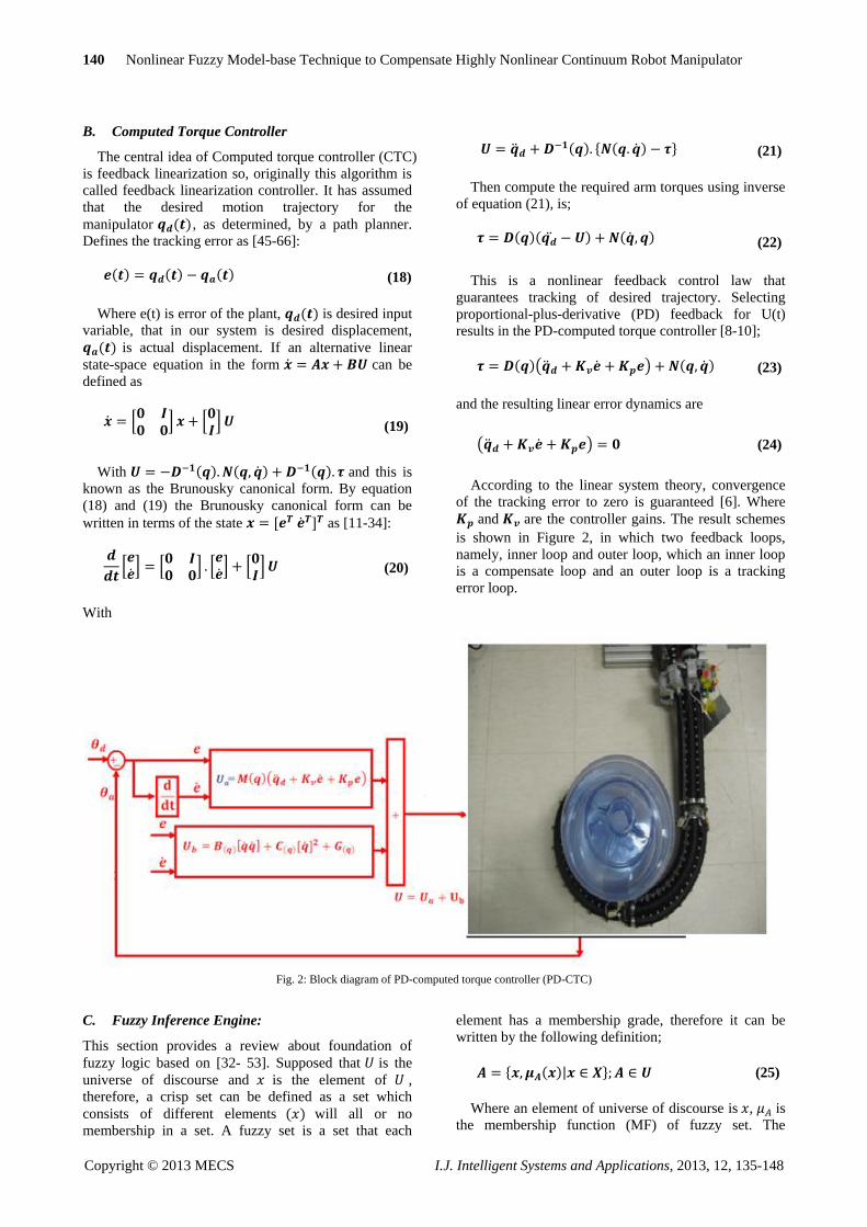
B. Computed Torque Controller
The central idea of Computed torque controller (CTC)
is feedback linearization so, originally this algorithm is
called feedback linearization controller. It has assumed
that the desired motion trajectory for the
manipulator ( ), as determined, by a path planner.
Defines the tracking error as [45-66]:
( ) ( ) ( ) (18)
Where e(t) is error of the plant, ( ) is desired input
variable, that in our system is desired displacement,
( ) is actual displacement. If an alternative linear
state-space equation in the form can be
defined as
0
1 0 1 (19)
With ( ) ( ) ( ) and this is
known as the Brunousky canonical form. By equation
(18) and (19) the Brunousky canonical form can be
written in terms of the state , - as [11-34]:
0 1 0
1 0 1 0
1 (20)
With
( ) * ( ) + (21)
Then compute the required arm torques using inverse
of equation (21), is;
( )( ) ( ) (22)
This is a nonlinear feedback control law that
guarantees tracking of desired trajectory. Selecting
proportional-plus-derivative (PD) feedback for U(t)
results in the PD-computed torque controller [8-10];
( )( ) ( ) (23)
and the resulting linear error dynamics are
( ) (24)
According to the linear system theory, convergence
of the tracking error to zero is guaranteed [6]. Where
and are the controller gains. The result schemes
is shown in Figure 2, in which two feedback loops,
namely, inner loop and outer loop, which an inner loop
is a compensate loop and an outer loop is a tracking
error loop.
Fig. 2: Block diagram of PD-computed torque controller (PD-CTC)
C. Fuzzy Inference Engine:
This section provides a review about foundation of
fuzzy logic based on [32- 53]. Supposed that is the
universe of discourse and is the element of ,
therefore, a crisp set can be defined as a set which
consists of different elements ( ) will all or no
membership in a set. A fuzzy set is a set that each
element has a membership grade, therefore it can be
written by the following definition;
* ( )| + (25)
Where an element of universe of discourse is , is
the membership function (MF) of fuzzy set. The

Nonlinear Fuzzy Model-base Technique to Compensate Highly Nonlinear Continuum Robot Manipulator 141
Copyright © 2013 MECS I.J. Intelligent Systems and Applications, 2013, 12, 135-148
membership function ( ( )) of fuzzy set must have
a value between zero and one. If the membership
function ( ) value equal to zero or one, this set
change to a crisp set but if it has a value between zero
and one, it is a fuzzy set. Defining membership function
for fuzzy sets has divided into two main groups; namely;
numerical and functional method, which in numerical
method each number has different degrees of
membership function and functional method used
standard functions in fuzzy sets. The membership
function which is often used in practical applications
includes triangular form, trapezoidal form, bell-shaped
form, and Gaussian form.
Linguistic variable can open a wide area to use of
fuzzy logic theory in many applications (e.g., control
and system identification). In a natural artificial
language all numbers replaced by words or sentences.
Rule statements are used to formulate the
condition statements in fuzzy logic. A single fuzzy
rule can be written by
(26)
where and are the Linguistic values that can be
defined by fuzzy set, the of the part of
is called the antecedent part and the of the part of is called the Consequent or
Conclusion part. The antecedent of a fuzzy if-then rule
can have multiple parts, which the following rules
shows the multiple antecedent rules:
(27)
where is error, is change of error, is Negative
Big, is Medium Left, is torque and is Large
Left. rules have three parts, namely, fuzzify
inputs, apply fuzzy operator and apply implication
method which in fuzzify inputs the fuzzy statements in
the antecedent replaced by the degree of membership,
apply fuzzy operator used when the antecedent has
multiple parts and replaced by single number between 0
to 1, this part is a degree of support for the fuzzy rule,
and apply implication method used in consequent of
fuzzy rule to replaced by the degree of membership.
The fuzzy inference engine offers a mechanism for
transferring the rule base in fuzzy set which it is divided
into two most important methods, namely, Mamdani
method and Sugeno method. Mamdani method is one of
the common fuzzy inference systems and he designed
one of the first fuzzy controllers to control of system
engine. Mamdani’s fuzzy inference system is divided
into four major steps: fuzzification, rule evaluation,
aggregation of the rule outputs and defuzzification.
Michio Sugeno use a singleton as a membership
function of the rule consequent part. The following
definition shows the Mamdani and Sugeno fuzzy rule
base
( )
(28)
When and have crisp values fuzzification
calculates the membership degrees for antecedent part.
Rule evaluation focuses on fuzzy operation ( )
in the antecedent of the fuzzy rules. The aggregation is
used to calculate the output fuzzy set and several
methodologies can be used in fuzzy logic controller
aggregation, namely, Max-Min aggregation, Sum-Min
aggregation, Max-bounded product, Max-drastic
product, Max-bounded sum, Max-algebraic sum and
Min-max. Two most common methods that used in
fuzzy logic controllers are Max-min aggregation and
Sum-min aggregation. Max-min aggregation defined as
below
( ) ⋃
( )
2 0 ( ) ( )13
(29)
The Sum-min aggregation defined as below
( ) ⋃
( )
∑ 0 ( ) ( )1
(30)
where is the number of fuzzy rules activated by
and and also ⋃
( ) is a fuzzy
interpretation of rule. Defuzzification is the last
step in the fuzzy inference system which it is used to
transform fuzzy set to crisp set. Consequently
defuzzification’s input is the aggregate output and the
defuzzification’s output is a crisp number. Centre of
gravity method ( ) and Centre of area method
( ) are two most common defuzzification methods,
which method used the following equation to
calculate the defuzzification
( ) ∑ ∑ ( )
∑ ∑ ( )
(31)
and method used the following equation to
calculate the defuzzification
( ) ∑ ( )
∑ ( ) (32)
Where ( ) and ( ) illustrates the
crisp value of defuzzification output, is discrete
element of an output of the fuzzy set, ( ) is
the fuzzy set membership function, and is the number
of fuzzy rules.
Based on foundation of fuzzy logic methodology;
fuzzy logic controller has played important rule to
design nonlinear controller for nonlinear and uncertain
systems [53-66]. However the application area for fuzzy

142 Nonlinear Fuzzy Model-base Technique to Compensate Highly Nonlinear Continuum Robot Manipulator
Copyright © 2013 MECS I.J. Intelligent Systems and Applications, 2013, 12, 135-148
control is really wide, the basic form for all command
types of controllers consists of;
Input fuzzification (binary-to-fuzzy[B/F]conversion)
Fuzzy rule base (knowledge base)
Inference engine
Output defuzzification (fuzzy-to-
binary[F/B]conversion).
III. Methodology
Gradient Descent Fuzzy Model-base Computed
Torque Optimization Algorithm
For computed torque controller application the
system performances are sensitive to the controller
coefficients ( ) . Therefore to have a good
response, compute the best value controller coefficients
are very important. Gradient descent algorithm is based
on improving the input parameters by moving
iteratively in the direction of the estimated gradient of
the response of interest. One of the major concerns with
this type of algorithm is the estimation of the gradient
and its statistical properties. Naturally, the heart of
gradient{based algorithms is the technique used to
estimate the gradient. Here we present the most
common methods used in the simulation optimization
literature. Gradient descent is based on the observation
that if the multivariable function ( ) is defined and
differentiable in a neighborhood of a point , then ( ) decreases fastest if one goes from in the direction of
the negative gradient of at , ( ). It follows
that, if
( ) (33)
for a small enough number, then ( ) ( ). With this observation in mind, one starts with a guess
for a local minimum of , and considers the
sequence such that
( ) (34)
We have
( ) ( ) ( ) (35)
So hopefully the sequence ( ) converges to the
desired local minimum. Note that the value of the step
size is allowed to change at every iteration. With
certain assumptions on the function (for example,
convex and Lipschitz) and particular choices of
(e.g., chosen via a line search that satisfies the Wolfe
conditions), convergence to a local minimum can be
guaranteed. When the function is convex, all local
minima are also global minima, so in this case gradient
descent can converge to the global solution.
IV. Results and Discussion
Gradient descent optimal algorithm computed torque
controller (GDACTC) was tested to Step response
trajectory. In this simulation, to control position of
continuum robot the first, second, and third joints are
moved from home to final position without and with
external disturbance. The simulation was implemented
in MATLAB/SIMULINK environment. These systems
are tested by band limited white noise with a predefined
40% of relative to the input signal amplitude. This type
of noise is used to external disturbance in continuous
and hybrid systems and applied to nonlinear dynamic of
these controllers.
Gradient descent optimal algorithm computed
torque controller Optimization: in GDA CTC;
controllers performance are depended on the
controller’s coefficient gain ( ). These two
coefficients are computed by GDA optimization;
Figures 3 and 4.
Fig. 3: Trajectory Gradient descent optimization in FMCTC
Fig. 4: Error; Gradient descent optimization in FMCTC
Tracking performances: Figure 5 shows tracking
performance for GDA-CTC and CTC without
disturbance. By trial and error coefficients
are; From the
0 5 10 15 20 25 30-1
0
1
2
3
4
5
6
Time
0 5 10 15 20 25 30-1
-0.8
-0.6
-0.4
-0.2
0
0.2
0.4
0.6
0.8
1
Time

Nonlinear Fuzzy Model-base Technique to Compensate Highly Nonlinear Continuum Robot Manipulator 143
Copyright © 2013 MECS I.J. Intelligent Systems and Applications, 2013, 12, 135-148
simulation for first, second, and third links, it was seen
that the different controller gains have the different
performance. Tuning parameters of CTC by trial and
error and gradient descent optimization for continuum
robot are shown in Table 1.
Table 1: Tuning parameters of a step CTC by trial and error
1 2 3 4
70 50 70 70
24 24 15 24
70 70 75 50
70 50 70 70
24 24 15 24
70 70 75 50
70 50 70 70
24 24 15 24
70 70 75 50
RMS error 2.276e-5 3.34e-5 0 3.7e-5
-3.81e-5 -5.6e-5 0 -6.2e-5
-3.81e-5 -5.6e-5 0 -6.2e-5
-3.81e-5 -5.6e-5 0 -6.2e-5
Fig. 5: GDA-FMCTC and CTC for First, second and third link
trajectory
By comparing step response trajectory without
disturbance in CTC and GDA FMCTC, it is found that
the GDACTC's overshoot (1.32%) is lower than CTC's
(6.44%).
Disturbance rejection: Figure 6 has shown the power
disturbance elimination in CTC and GDA CTC. The
main target in this controller is disturbance rejection as
well as the other responses. A band limited white noise
with predefined of 40% the power of input signal is
applied to CTC and GDA CTC. It found fairly
fluctuations in trajectory responses. As mentioned
earlier, CTC works very well when all parameters are
known.
Fig. 6: GDA-FMCTC and CTC for First, second and third link
trajectory with disturbance
Among above graph (6) relating to step trajectory
following with external disturbance, GDA CTC and
CTC have fairly fluctuations. By comparing some
control parameters such as overshoot, rise time, steady
state and RMS error it computed that the GDACTC's
overshoot (1.8%) is lower than CTC's (8%), although
both of them have about the same rise time; GDA CTC
(0.5 sec) and CTC (0.41 sec), the Steady State and RMS
error in GDACTC (Steady State error = -0.0019 and
RMS error=0.0025) is fairly lower than CTC (Steady
State error and RMS error= ).
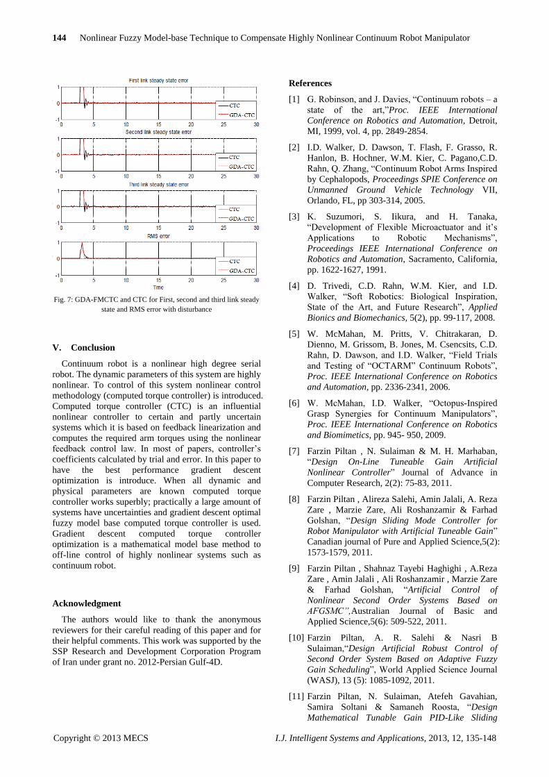
Errors in the model: Figure 7 has shown the error
disturbance in CTC and GDA CTC. The controllers
with no external disturbances have the same error
response, but GDA CTC has the better steady state error
when the continuum robot has external disturbance.
Furthermore the RMS error profile for GDA CTC is
sharply dropped compared to the CTC.
The error in GDA CTC and CTC is widely increased
among of error graphs (relating to Step response with
external disturbance. By comparing the steady state and
RMS error it observed that the GDA CTC's steady state
and RMS error (Steady State error = -0.0019 and
RMS error=0.0025) is lower than CTC's (Steady State
error and RMS error= ). When
applied disturbance in these controllers it is computed
that the steady state and RMS error in CTC increased
rapidly approximately 130% but in GDA CTC it is
approximately 22%.
144 Nonlinear Fuzzy Model-base Technique to Compensate Highly Nonlinear Continuum Robot Manipulator
Copyright © 2013 MECS I.J. Intelligent Systems and Applications, 2013, 12, 135-148
Fig. 7: GDA-FMCTC and CTC for First, second and third link steady
state and RMS error with disturbance
V. Conclusion
Continuum robot is a nonlinear high degree serial
robot. The dynamic parameters of this system are highly
nonlinear. To control of this system nonlinear control
methodology (computed torque controller) is introduced.
Computed torque controller (CTC) is an influential
nonlinear controller to certain and partly uncertain
systems which it is based on feedback linearization and
computes the required arm torques using the nonlinear
feedback control law. In most of papers, controller’s
coefficients calculated by trial and error. In this paper to
have the best performance gradient descent
optimization is introduce. When all dynamic and
physical parameters are known computed torque
controller works superbly; practically a large amount of
systems have uncertainties and gradient descent optimal
fuzzy model base computed torque controller is used.
Gradient descent computed torque controller
optimization is a mathematical model base method to
off-line control of highly nonlinear systems such as
continuum robot.
Acknowledgment
The authors would like to thank the anonymous
reviewers for their careful reading of this paper and for
their helpful comments. This work was supported by the
SSP Research and Development Corporation Program
of Iran under grant no. 2012-Persian Gulf-4D.
References
[1] G. Robinson, and J. Davies, “Continuum robots – a
state of the art,”Proc. IEEE International
Conference on Robotics and Automation, Detroit,
MI, 1999, vol. 4, pp. 2849-2854.
[2] I.D. Walker, D. Dawson, T. Flash, F. Grasso, R.
Hanlon, B. Hochner, W.M. Kier, C. Pagano,C.D.
Rahn, Q. Zhang, “Continuum Robot Arms Inspired
by Cephalopods, Proceedings SPIE Conference on
Unmanned Ground Vehicle Technology VII,
Orlando, FL, pp 303-314, 2005.
[3] K. Suzumori, S. Iikura, and H. Tanaka,
“Development of Flexible Microactuator and it’s
Applications to Robotic Mechanisms”,
Proceedings IEEE International Conference on
Robotics and Automation, Sacramento, California,
pp. 1622-1627, 1991.
[4] D. Trivedi, C.D. Rahn, W.M. Kier, and I.D.
Walker, “Soft Robotics: Biological Inspiration,
State of the Art, and Future Research”, Applied
Bionics and Biomechanics, 5(2), pp. 99-117, 2008.
[5] W. McMahan, M. Pritts, V. Chitrakaran, D.
Dienno, M. Grissom, B. Jones, M. Csencsits, C.D.
Rahn, D. Dawson, and I.D. Walker, “Field Trials
and Testing of “OCTARM” Continuum Robots”,
Proc. IEEE International Conference on Robotics
and Automation, pp. 2336-2341, 2006.
[6] W. McMahan, I.D. Walker, “Octopus-Inspired
Grasp Synergies for Continuum Manipulators”,
Proc. IEEE International Conference on Robotics
and Biomimetics, pp. 945- 950, 2009.
[7] Farzin Piltan , N. Sulaiman & M. H. Marhaban,
“Design On-Line Tuneable Gain Artificial
Nonlinear Controller” Journal of Advance in
Computer Research, 2(2): 75-83, 2011.
[8] Farzin Piltan , Alireza Salehi, Amin Jalali, A. Reza
Zare , Marzie Zare, Ali Roshanzamir & Farhad
Golshan, “Design Sliding Mode Controller for
Robot Manipulator with Artificial Tuneable Gain”
Canadian journal of Pure and Applied Science,5(2):
1573-1579, 2011.
[9] Farzin Piltan , Shahnaz Tayebi Haghighi , A.Reza
Zare , Amin Jalali , Ali Roshanzamir , Marzie Zare
& Farhad Golshan, “Artificial Control of
Nonlinear Second Order Systems Based on
AFGSMC ,Australian Journal of Basic and
Applied Science,5(6): 509-522, 2011.
[10] Farzin Piltan, A. R. Salehi & Nasri B
Sulaiman,“Design Artificial Robust Control of
Second Order System Based on Adaptive Fuzzy
Gain Scheduling”, World Applied Science Journal
(WASJ), 13 (5): 1085-1092, 2011.
[11] Farzin Piltan, N. Sulaiman, Atefeh Gavahian,
Samira Soltani & Samaneh Roosta, “Design
Mathematical Tunable Gain PID-Like Sliding

Nonlinear Fuzzy Model-base Technique to Compensate Highly Nonlinear Continuum Robot Manipulator 145
Copyright © 2013 MECS I.J. Intelligent Systems and Applications, 2013, 12, 135-148
Mode Fuzzy Controller with Minimum Rule Base”,
International Journal of Robotic and Automation, 2
(3): 146-156, 2011.
[12] Farzin Piltan , N. Sulaiman, Zahra Tajpaykar,
Payman Ferdosali & Mehdi Rashidi, “Design
Artificial Nonlinear Robust Controller Based on
CTLC and FSMC with Tunable Gain”,
International Journal of Robotic and Automation, 2
(3): 205-220, 2011.
[13] Farzin Piltan, N. Sulaiman, M. H. Marhaban, Adel
Nowzary & Mostafa Tohidian, “Design of FPGA-
based Sliding Mode Controller for Robot
Manipulator”, International Journal of Robotic and
Automation, 2 (3): 183-204, 2011.
[14] Farzin Piltan, N. Sulaiman, Samaneh Roosta, M.H.
Marhaban & R. Ramli, “Design a New Sliding
Mode Adaptive Hybrid Fuzzy Controller”, Journal
of Advanced Science & Engineering Research, 1
(1): 115-123, 2011.
[15] Farzin Piltan, Atefe Gavahian, N. Sulaiman & M.
H. Marhaban, “Novel Sliding Mode Controller for
Robot Manipulator using FPGA”, Journal of
Advanced Science & Engineering Research, 1 (1):
115-123, 2011.
[16] Farzin Piltan, N. Sulaiman, Payman Ferdosali &
Iraj Assadi Talooki, “Design Model Free Fuzzy
Sliding Mode Control: Applied to Internal
Combustion Engine”, International Journal of
Engineering, 5 (4):302-312, 2011.
[17] Farzin Piltan, N. Sulaiman, A. Jalali & F. Danesh
Narouei, “Design of Model Free Adaptive Fuzzy
Computed Torque Controller: Applied to
Nonlinear Second Order System”, International
Journal of Robotics and Automation, 2 (4):245-257,
2011
[18]Farzin Piltan, A. Jalali & N. Sulaiman, “Design of
PC-Based Sliding Mode Controller and
Normalized Sliding Surface Slope Using PSO
Method For Robot Manipulator”, International
Journal of Robotics and Automation,2 (4): 298-316,
2011.
[19] Farzin Piltan, Amin Jalali, N. Sulaiman, Atefeh
Gavahian & Sobhan Siamak, “Novel Artificial
Control of Nonlinear Uncertain System: Design a
Novel Modified PSO SISO Lyapunov Based Fuzzy
Sliding Mode Algorithm”, International Journal of
Robotics and Automation, 2 (5): 298-316, 2011.
[20] Farzin Piltan, N. Sulaiman, Iraj Asadi Talooki &
Payman Ferdosali, “Control of IC Engine: Design
a Novel MIMO Fuzzy Backstepping Adaptive
Based Fuzzy Estimator Variable Structure
Control”, International Journal of Robotics and
Automation, 2 (5):360-380, 2011.
[21] Farzin Piltan, N. Sulaiman, S.Soltani, M. H.
Marhaban & R. Ramli, “An Adaptive Sliding
Surface Slope Adjustment in PD Sliding Mode
Fuzzy Control For Robot Manipulator ,
International Journal of Control and Automation, 4
(3): 65-76, 2011.
[22] Farzin Piltan, N. Sulaiman, Mehdi Rashidi, Zahra
Tajpaikar & Payman Ferdosali, “Design and
Implementation of Sliding Mode Algorithm:
Applied to Robot Manipulator-A Review”,
International Journal of Robotics and Automation,
2 (5):265-282, 2011.
[23] Farzin Piltan, N. Sulaiman , Arash Zargari,
Mohammad Keshavarz & Ali Badri, “Design PID-
Like Fuzzy Controller with Minimum Rule Base
and Mathematical Proposed On-line Tunable Gain:
Applied to Robot Manipulator”, International
Journal of Artificial Intelligence and Expert
System, 2 (4):184-195, 2011.
[24] Farzin Piltan, SH. Tayebi HAGHIGHI, N.
Sulaiman, Iman Nazari & Sobhan Siamak,
Artificial Control of PUMA Robot Manipulator:
A-Review of Fuzzy Inference Engine and
Application to Classical Controller , International
Journal of Robotics and Automation, 2 (5):401-425,
2011.
[25] Samira Soltani & Farzin Piltan, “Design Artificial
Nonlinear Controller Based on Computed Torque
like Controller with Tunable Gain”, World
Applied Science Journal (WASJ), 14 (9): 1306-
1312, 2011.
[26] Farzin Piltan, N. Sulaiman & I.AsadiTalooki,
“Evolutionary Design on-line Sliding Fuzzy Gain
Scheduling Sliding Mode Algorithm: Applied to
Internal Combustion Engine”, International
Journal of Engineering Science and Technology, 3
(10):7301-7308, 2011.
[27] Farzin Piltan, Nasri B Sulaiman, Iraj Asadi Talooki
& Payman Ferdosali, Designing On-Line Tunable
Gain Fuzzy Sliding Mode Controller Using Sliding
Mode Fuzzy Algorithm: Applied to Internal
Combustion Engine World Applied Science
Journal (WASJ), 15 (3): 422-428, 2011.
[28] Farzin Piltan , A. Zare, Nasri B. Sulaiman, M. H.
Marhaban & R. Ramli, “A Model Free Robust
Sliding Surface Slope Adjustment in Sliding Mode
Control for Robot Manipulator”, World Applied
Science Journal (WASJ), 12 (12): 2330-2336,
2011.
[29] Farzin Piltan , A. H. Aryanfar, Nasri B. Sulaiman,
M. H. Marhaban & R. Ramli, “Design Adaptive
Fuzzy Robust Controllers for Robot Manipulator”,
World Applied Science Journal (WASJ), 12 (12):
2317-2329, 2011.
[30] Farzin Piltan, N. Sulaiman, Payman Ferdosali,
Mehdi Rashidi & Zahra Tajpeikar, “Adaptive
MIMO Fuzzy Compensate Fuzzy Sliding Mode
Algorithm: Applied to Second Order Nonlinear

146 Nonlinear Fuzzy Model-base Technique to Compensate Highly Nonlinear Continuum Robot Manipulator
Copyright © 2013 MECS I.J. Intelligent Systems and Applications, 2013, 12, 135-148
System”, International Journal of Engineering, 5
(5): 380-398, 2011.
[31] Farzin Piltan, N. Sulaiman, Hajar Nasiri, Sadeq
Allahdadi & Mohammad A. Bairami, “Novel
Robot Manipulator Adaptive Artificial Control:
Design a Novel SISO Adaptive Fuzzy Sliding
Algorithm Inverse Dynamic Like Method ,
International Journal of Engineering, 5 (5): 399-
418, 2011.
[32] Farzin Piltan, N. Sulaiman, Sadeq Allahdadi,
Mohammadali Dialame & Abbas Zare, “Position
Control of Robot Manipulator: Design a Novel
SISO Adaptive Sliding Mode Fuzzy PD Fuzzy
Sliding Mode Control”, International Journal of
Artificial Intelligence and Expert System, 2
(5):208-228, 2011.
[33] Farzin Piltan, N. Sulaiman, Amin Jalali & Koorosh
Aslansefat, “Evolutionary Design of Mathematical
tunable FPGA Based MIMO Fuzzy Estimator
Sliding Mode Based Lyapunov Algorithm: Applied
to Robot Manipulator”, International Journal of
Robotics and Automation, 2 (5):317-343, 2011.
[34] Farzin Piltan, N. Sulaiman, Abbas Zare,
Mohammadali Dialame & Sadeq Allahdadi,
“Design Adaptive Fuzzy Inference Sliding Mode
Algorithm: Applied to Robot Arm”, International
Journal of Robotics and Automation,3 (1):283-297,
2011.
[35] Farzin Piltan, N. Sulaiman, Samaneh Roosta,
Atefeh Gavahian & Samira Soltani, “Evolutionary
Design of Backstepping Artificial Sliding Mode
Based Position Algorithm: Applied to Robot
Manipulator , International Journal of
Engineering, 5 (5):419-434, 2011.
[36]Farzin Piltan, N. Sulaiman, Amin Jalali, Sobhan
Siamak & Iman Nazari, “Control of Robot
Manipulator: Design a Novel Tuning MIMO Fuzzy
Backstepping Adaptive Based Fuzzy Estimator
Variable Structure Control”, International Journal
of Control and Automation, 4 (4):91-110, 2011.
[37] Farzin Piltan, N. Sulaiman, Atefeh Gavahian,
Samaneh Roosta & Samira Soltani, “On line
Tuning Premise and Consequence FIS: Design
Fuzzy Adaptive Fuzzy Sliding Mode Controller
Based on Lyaponuv Theory”, International Journal
of Robotics and Automation, 2 (5):381-400, 2011.
[38] Farzin Piltan, N. Sulaiman, Samira Soltani,
Samaneh Roosta & Atefeh Gavahian, Artificial
Chattering Free on-line Fuzzy Sliding Mode
Algorithm for Uncertain System: Applied in Robot
Manipulator , International Journal of
Engineering, 5 (5):360-379, 2011.
[39] Farzin Piltan, Mohammad A.Bairami, Farid
Aghayari & Sadeq Allahdadi, “Design Adaptive
Artificial Inverse Dynamic Controller: Design
Sliding Mode Fuzzy Adaptive New Inverse
Dynamic Fuzzy Controller”, International Journal
of Robotics and Automation, (1):13-26, 2011.
[40] Farzin Piltan, Sadeq Allahdadi, Mohammad
A.Bairami & Hajar Nasiri, “Design Auto Adjust
Sliding Surface Slope: Applied to Robot
Manipulator”, International Journal of Robotics
and Automation, 3 (1):27-44, 2011.
[41] Farzin Piltan, Mohammadali Dialame, Abbas Zare
& Ali Badri, “Design Novel Lookup Table
Changed Auto Tuning FSMC:Applied to Robot
Manipulator”, International Journal of Engineering,
6 (1):25-41, 2012.
[42] Farzin Piltan, M. Keshavarz, A. Badri & A.
Zargari, Design Novel Nonlinear Controller
Applied to RobotManipulator: Design New
Feedback Linearization Fuzzy Controller with
Minimum Rule Base Tuning Method ,
International Journal of Robotics and Automation,
3 (1):1-12, 2012.
[43] Farzin Piltan, Mohammad A.Bairami, Farid
Aghayari & Sadeq Allahdadi, “Design Adaptive
Artificial Inverse Dynamic Controller: Design
Sliding Mode Fuzzy Adaptive New Inverse
Dynamic Fuzzy Controller”, International Journal
of Robotics and Automation, (1):13-26, 2012.
[44] Farzin Piltan, Sadeq Allahdadi, Mohammad
A.Bairami & Hajar Nasiri, “Design Auto Adjust
Sliding Surface Slope: Applied to Robot
Manipulator”, International Journal of Robotics
and Automation, 3 (1):27-44, 2012.
[45] Farzin Piltan, F. Aghayari, M. Rashidian & M.
Shamsodini, A New Estimate Sliding Mode Fuzzy
Controller for RoboticManipulator , International
Journal of Robotics and Automation, 3 (1):45-60,
2012
[46] Farzin Piltan, Iman Nazari, Sobhan Siamak,
Payman Ferdosali, Methodology of FPGA-Based
Mathematical error-Based Tuning Sliding Mode
Controller , International Journal of Control and
Automation, 5(1), 89-118, 2012.
[47] Farzin Piltan, Bamdad Boroomand, Arman Jahed
& Hossein Rezaie, Methodology of Mathematical
Error-Based Tuning Sliding Mode Controller”,
International Journal of Engineering, 6 (2):96-117,
2012.
[48] Farzin Piltan, S. Emamzadeh, Z. Hivand, F.
Shahriyari & Mina Mirazaei. PUMA-560 Robot
Manipulator Position Sliding Mode Control
Methods Using MATLAB/SIMULINK and Their
Integration into Graduate/Undergraduate
Nonlinear Control, Robotics and MATLAB
Courses , International Journal of Robotics and
Automation, 3(3):106-150, 2012.
[49] Farzin Piltan, A. Hosainpour, E. Mazlomian,
M.Shamsodini, M.H Yarmahmoudi. Online

Nonlinear Fuzzy Model-base Technique to Compensate Highly Nonlinear Continuum Robot Manipulator 147
Copyright © 2013 MECS I.J. Intelligent Systems and Applications, 2013, 12, 135-148
Tuning Chattering Free Sliding Mode Fuzzy
Control Design: Lyapunov Approach ,
International Journal of Robotics and Automation,
3(3):77-105, 2012.
[50] Farzin Piltan, R. Bayat, F. Aghayari, B.
Boroomand. Design Error-Based Linear Model-
Free Evaluation Performance Computed Torque
Controller , International Journal of Robotics and
Automation, 3(3):151-166, 2012.
[51] Farzin Piltan, J. Meigolinedjad, S. Mehrara, S.
Rahmdel. Evaluation Performance of 2nd Order
Nonlinear System: Baseline Control Tunable Gain
Sliding Mode Methodology , International Journal
of Robotics and Automation, 3(3): 192-211, 2012.
[52] Farzin Piltan, Mina Mirzaei, Forouzan Shahriari,
Iman Nazari, Sara Emamzadeh, “Design Baseline
Computed Torque Controller”, International
Journal of Engineering, 6(3): 129-141, 2012.
[53] Farzin Piltan, Sajad Rahmdel, Saleh Mehrara, Reza
Bayat, “Sliding Mode Methodology Vs. Computed
Torque Methodology Using
MATLAB/SIMULINK and Their Integration into
Graduate Nonlinear Control Courses” ,
International Journal of Engineering, 6(3): 142-177,
2012.
[54] Farzin Piltan , M.H. Yarmahmoudi, M.
Shamsodini, E.Mazlomian,
A.Hosainpour. PUMA-560 Robot Manipulator
Position Computed Torque Control Methods Using
MATLAB/SIMULINK and Their Integration into
Graduate Nonlinear Control and MATLAB
Courses , International Journal of Robotics and
Automation, 3(3): 167-191, 2012.
[55] Farzin Piltan, Hossein Rezaie, Bamdad
Boroomand, Arman Jahed. “Design Robust
Backstepping on-line Tuning Feedback
Linearization Control Applied to IC Engine”,
International Journal of Advance Science and
Technology, 11:40-22, 2012.
[56]Farzin Piltan, S. Siamak, M.A. Bairami and I.
Nazari. Gradient Descent Optimal Chattering
Free Sliding Mode Fuzzy Control Design:
Lyapunov Approach , International Journal of
Advanced Science and Technology, 43: 73-90,
2012.
[57] Farzin Piltan, M.R. Rashidian, M. Shamsodini and
S. Allahdadi. Effect of Rule Base on the Fuzzy-
Based Tuning Fuzzy Sliding Mode Controller:
Applied to 2nd Order Nonlinear System ,
International Journal of Advanced Science and
Technology, 46:39-70, 2012.
[58] Farzin Piltan, A. Jahed, H. Rezaie and B.
Boroomand. Methodology of Robust Linear On-
line High Speed Tuning for Stable Sliding Mode
Controller: Applied to Nonlinear System ,
International Journal of Control and Automation,
5(3): 217-236, 2012.
[59]Farzin Piltan, R. Bayat, S. Mehara and J.
Meigolinedjad. GDO Artificial Intelligence-
Based Switching PID Baseline Feedback
Linearization Method: Controlled PUMA
Workspace , International Journal of Information
Engineering and Electronic Business, 5: 17-26,
2012.
[60]Farzin Piltan, B. Boroomand, A. Jahed and H.
Rezaie. Performance-Based Adaptive Gradient
Descent Optimal Coefficient Fuzzy Sliding Mode
Methodology , International Journal of Intelligent
Systems and Applications, 11: 40-52 2012.
[61] Farzin Piltan, S. Mehrara, R. Bayat and S.
Rahmdel. Design New Control Methodology of
Industrial Robot Manipulator: Sliding Mode
Baseline Methodology , International Journal of
Hybrid Information Technology, 5(4):41-54, 2012.
[62] AH Aryanfar, MR Khammar, Farzin Piltan,
“Design a robust self-tuning fuzzy sliding mode
control for second order systems”, International
Journal of Engineering Science REsearch, 3(4):
711-717, 2012.
[63] Farzin Piltan, Shahnaz Tayebi Haghighi, “Design
Gradient Descent Optimal Sliding Mode Control
of Continuum Robots”, International Journal of
Robotics and Automation, 1(4): 175-189, 2012.
[64] Farzin Piltan, NB Sulaiman, “Review of Sliding
Mode Control of Robotic Manipulator”, World
Applied Sciences Journal, 18 (12), 1855-1869,
2012.
[65] Farzin Piltan, M. Akbari, M. Piran , M.
Bazregar. ”Design Model Free Switching Gain
Scheduling Baseline Controller with Application to
Automotive Engine”, International Journal of
Information Technology and Computer Science,
01:65-73, 2013.
[66] Farzin Piltan, M. Piran , M. Bazregar, M. Akbari,
“Design High Impact Fuzzy Baseline Variable
Structure Methodology to Artificial Adjust Fuel
Ratio”, International Journal of Intelligent Systems
and Applications, 02: 59-70, 2013.
Authors' Profiles
Farzin Piltan was born on 1975,
Shiraz, Iran. In 2004 he is jointed the
research and development company,
SSP Co, Shiraz, Iran. In addition to 7
textbooks, Farzin Piltan is the main
author of more than 70 scientific
papers in refereed journals. He is
editorial board of international journal of control and
automation (IJCA), editorial board of International

148 Nonlinear Fuzzy Model-base Technique to Compensate Highly Nonlinear Continuum Robot Manipulator
Copyright © 2013 MECS I.J. Intelligent Systems and Applications, 2013, 12, 135-148
Journal of Intelligent System and Applications (IJISA),
editorial board of IAES international journal of robotics
and automation, editorial board of International Journal
of Reconfigurable and Embedded Systems and reviewer
of (CSC) international journal of robotics and
automation. His main areas of research interests are
nonlinear control, artificial control system and applied
to FPGA, robotics and artificial nonlinear control and
IC engine modelling and control.
Mehdi Eram is an electrical engineer
researcher at research and
development company SSP. Co. His
research activities deal with the
robotics and artificial nonlinear control.
Mohammad Taghavi is a
mechanical engineer at research and
development company SSP. Co. His
main areas are nonlinear control,
artificial control system and robotics.
Omid Reza Sadrnia is a
communication and electrical
engineer researcher at research and
development company SSP. Co. He
is now pursuing his Master in
communication engineering at Shiraz
University. His research activities
deal with the robotics and artificial nonlinear control.
Mahdi Jafari is a communication
and electrical engineer researcher at
research and development company
SSP. Co. He is now pursuing his
Master in communication
engineering at Shiraz University.
His research activities deal with the robotics and
artificial nonlinear control.