Fuzzy control of robot manipulator with a flexible tool
16
Fuzzy Control of Robot Manipulator with a Flexible Tool Aria Alasty and Ali Sepehri Center of Excellence in Design, Robotics, and Automation (CEDRA), Department of Mechanical Engineering Sharif University of Technology Azady Ave. Tehran, Iran e-mail: [email protected], [email protected] Received 2 March 2004; accepted 7 February 2005 In some tasks, a rigid robot manipulator handles a long, slender, and flexible tool, which usually has not been equipped with vibration measuring devices. This situation makes a different tool tip position control problem. In this paper, a new method will be presented for simultaneous tip position and vibration suppression control of a flexible tool on a rigid-link 3-DOF robot. This approach uses fuzzy logic rule-based controllers without us- ing any sensors and actuators on the tool or a priori knowledge about the tool. Numerical simulation of robot and tool set has been accomplished and results support the fact that designed fuzzy controllers perform remarkably well in reducing vibrations and precision guidance of robot tool tip for tracking various trajectories. © 2005 Wiley Periodicals, Inc. 1. INTRODUCTION Initial studies on robotic systems have generally con- centrated on rigid system models partly due to non- linear and coupled nature of dynamic equations, and partly due to the rugged design and low operational speed of these systems. However, as demand on op- erational speed increases, and contemporary designs call for high payload capacity with relatively light structures and compliant joint components such as harmonic drives, a more detailed and realistic system model is needed not only for control purpose, but also for design consideration as well. One of the most important cases is to study flexibility of system com- ponents. In general, the overall structural flexibility in robotic manipulator is affected by four factors: • Flexibility in robot links. • Flexibility in robot joints due to elastic proper- ties of power transmission elements (gears, shafts, harmonic drives, etc.). 1 • Flexibility in environment or bodies on which end effector does work. • Flexibility in tools or devices attached to the end effector to perform a special task. • • • • • • • • • • • • • • • • • • • • • • • • • • • • • • • Journal of Robotic Systems 22(7), 367–382 (2005) © 2005 Wiley Periodicals, Inc. Published online in Wiley InterScience (www.interscience.wiley.com). • DOI: 10.1002/rob.20072
Transcript of Fuzzy control of robot manipulator with a flexible tool
Fuzzy Control of RobotManipulator with a Flexible
Tool
Aria Alasty and Ali SepehriCenter of Excellence in Design, Robotics,and Automation (CEDRA),Department of Mechanical EngineeringSharif University of TechnologyAzady Ave.Tehran, Irane-mail: [email protected], [email protected]
Received 2 March 2004; accepted 7 February 2005
In some tasks, a rigid robot manipulator handles a long, slender, and flexible tool, whichusually has not been equipped with vibration measuring devices. This situation makesa different tool tip position control problem. In this paper, a new method will be presentedfor simultaneous tip position and vibration suppression control of a flexible tool on arigid-link 3-DOF robot. This approach uses fuzzy logic rule-based controllers without us-ing any sensors and actuators on the tool or a priori knowledge about the tool. Numericalsimulation of robot and tool set has been accomplished and results support the fact thatdesigned fuzzy controllers perform remarkably well in reducing vibrations and precisionguidance of robot tool tip for tracking various trajectories. © 2005 Wiley Periodicals, Inc.
• • • • • • • • • • • • • • • • • • • • • • • • • • • • • • •
1. INTRODUCTION
Initial studies on robotic systems have generally con-centrated on rigid system models partly due to non-linear and coupled nature of dynamic equations, andpartly due to the rugged design and low operationalspeed of these systems. However, as demand on op-erational speed increases, and contemporary designscall for high payload capacity with relatively lightstructures and compliant joint components such asharmonic drives, a more detailed and realistic systemmodel is needed not only for control purpose, but
Journal of Robotic Systems 22(7), 367–382 (2005) © 2005 WileyPublished online in Wiley InterScience (www.interscience.wiley.co
also for design consideration as well. One of the mostimportant cases is to study flexibility of system com-ponents. In general, the overall structural flexibilityin robotic manipulator is affected by four factors:
• Flexibility in robot links.• Flexibility in robot joints due to elastic proper-
ties of power transmission elements (gears, shafts,harmonic drives, etc.).1
• Flexibility in environment or bodies on whichend effector does work.
• Flexibility in tools or devices attached to theend effector to perform a special task.
Periodicals, Inc.m). • DOI: 10.1002/rob.20072
368 • Journal of Robotic Systems—2005
Due to existence of high grasping forces and vi-brations of flexible components and in order to keepaccuracy of robots operating in high speeds, consid-ering the effect of these factors on system modeling,design and control processes is necessary. The effectof each factor on the system response is highly depen-dent on robot physical characteristics. Flexural be-havior in an already highly nonlinear robotic systemconsiderably complicates analysis and design, anddemands elaborate control schemes with attendantrequirement for sophisticated hardware/software.This has resulted in increased research activity intomethods of actively influencing flexible manipulatorbehavior. In recent years, several investigations havebeen done in the field of modeling and controlling offlexible robots. Some of which are works of Zheng-Hau Luo and Boa-Zhu Gua,2 Mohri, Sarkar andYamamoto,3 and Zheng-Hau Luo and De-Xing Feng.4
Almost in all of these researches, the flexible elementof the system is a fixed component of robot mecha-nism (first or second flexibility factors in manipula-tors). In some applications, it is required to attach along, slender and flexible tool to the end effector of arigid robot. In these cases the tool flexibility is suchhigh that the flexibility of robot elements can be ig-nored (robot joints and links can be considered rigid).Meanwhile, these problems have two difficulties:
• Direct installation of vibration measuring sen-sors on flexible tools is not desired. Since the flexibletool can be any optional object, which is temporarilygrasped by the robot gripper, attaching a vibrationmeasuring device on it degrades the measure of quicktool changeability of the robot.
• Physical characteristics (size, mass and stiff-ness) of flexible tools are variable. Thus the robot con-trol system design must be so that estimation and cal-culation of these parameters and regulation ofcontrollers relative to system condition will be pos-sible.
This situation makes a different tool tip positioncontrol problem, which has seldom been consideredin the previous investigations. In Sun, Mills and Liuworks5,6 position control of a flexible object, which iscarried cooperatively with several robots, has beenstudied. In these researches, vibrations are only sup-pressed by flexible object structural damping. In ad-dition, effect of gravity terms of this object has notbeen compensated in dynamic equations. In Ka-layeioglu, Giray and Asmer work7 vibration control isperformed by piezoelectric actuators attached to flex-ible body.
In this paper, position control and vibration sup-pression of flexible tools used by a rigid robot in per-
forming various tasks has been studied. The manipu-lator, which has been considered here, is a 3-DOFrobot composes of three rigid links, two prismaticjoints and one revolute joint. Flexible tools of optionaldimensions and physical characteristics are mountedon the robot end effector. The main objective is tomeet control requirements without any need to attachsensors and actuators to the robot tools. For this pur-pose, fuzzy controllers with a force/torque sensor at-tached to the robot wrist are being used. By imple-mentation of this method there is no need to attachspecial expensive sensors such as piezoelectric, straingauge and or accelerometer to the tools. Therefore,any kind of flexible tools usable in industry, agricul-ture, medicine, space and nuclear related activities,etc. can easily be applied in this robot.
The following sections describe the efforts to-ward achievement of the goals of this research. In Sec-tion 2, using Newton-Euler recursive dynamic algo-rithm, the nonlinear ordinary differential equations(ODE) of rigid robot motion are derived. The end ef-fector’s grasping torque/forces relate this set of equa-tions to the tool vibration equation which will be de-rived in Section 3. In this section, tool vibration linearpartial differential equation (PDE) is derived andnatural frequencies and mode shapes are calculatedusing variables separation method and applyingboundary conditions. Then using mode summationmethod, Lagrange equations and principle of or-thogonality of mode shapes, the forced vibrations areanalyzed and ordinary differential equations are ob-tained in terms of generalized coordinates of vibra-tion modes. These equations are coupled with non-linear equations of rigid body motion via forceapplied per unit length of the tool. By simultaneousanalysis of these two sets of equations, robot jointsposition and velocities, generalized coordinates oftool vibration modes and their first derivatives arecalculated. In Section 4, on the basis of fuzzy logictheory, suitable controllers are designed and appliedso as to control the position of the robot tool tip, andalso to reduce its oscillation during trajectory track-ing. A novel technique is introduced for calculatingthe generalized coordinates of vibration modes andtheir first derivatives (inputs of vibration modesfuzzy controllers) by mounting a force/torque uni-versal sensor at the robot wrist. The results of numeri-cal simulation of robot, tool and controllers set is pre-sented in Section 5.
2. DYNAMICS OF A 3-DOF ROBOTIn this paper, a 3-DOF robot, with capability of vari-ous tools attachment has been studied. A schematic
Alasty and Sepehri: Fuzzy Control of Robot Manipulator • 369
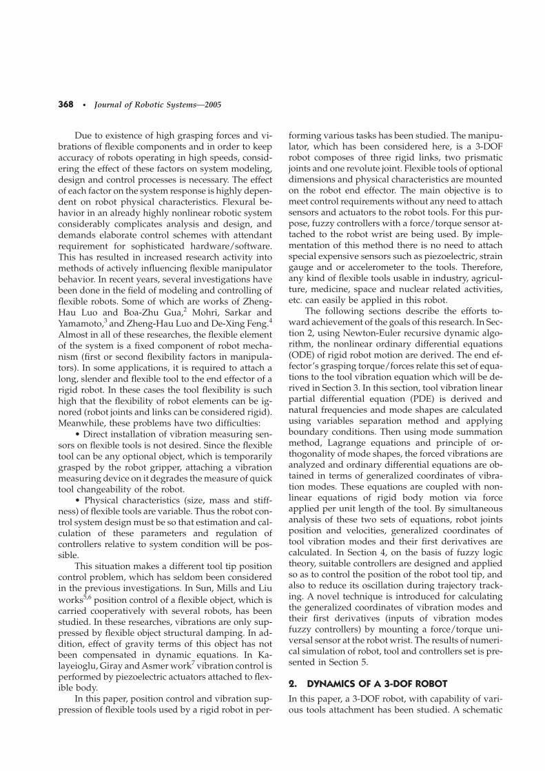
Figure 1. Schematic of 3-DOF robot and a flexible tool.
view of the robot and its attached tool is illustrated inFigure 1. The above-mentioned robot has r, �, and zmotions in a predefined vertical plane under theearth gravity effect. These motions in robot work-plane are provided by prismatic (z), revolute (�), andprismatic (r) joints (PRP), respectively. Every threelinks are considered rigid and their motions out of thework plane directions are prevented using suitableconstraints. Tools are assumed homogeneous anduniform and their length, width, height, and densityare L4 , w4 , h4 , and �4 , respectively. In order to de-
scribe robot links position and orientation, variousframes are attached to robot links (Figure 1).
Using Newton-Euler equations, the nonlinear dy-namic equations are obtained as follows:
�1���m3�L21�r�r3��m2r2�cos ����m1�m2
�m3� z��m3 sin �� r��2m3 cos �� r ����m2r2
�m3�L21�r�r3��sin ��2��1� z��m1�m2
�m3�g�� fx cos ��fz sin �� ,
370 • Journal of Robotic Systems—2005
�2� �I2�I3�m2r22�m3�L21�r�r3�2� ����m3�L21�r
�r3��m2r2�cos �� z�g ���2m3�L21�r�r3�� r �
��2����My��L21�r�L3�fx� , (1)
�3��m3 sin ��� z�g ���m3� r��m3�L21�r�r3���2
��3� r�� fz� ,
where My , fx , fz are grasping torque/forces of robotgripper; m1 , m2 , m3 are mass of robot links; I2 , I3 aresecond and third links’ mass moment of inertia withrespect to Z and Y axes of the frames connected totheir center of masses; r2 , r3 are location of secondand third links’ center of mass with respect to frames�2, �3; and 1 , 2 , 3 are coefficients of viscous fric-tion in robot joints.
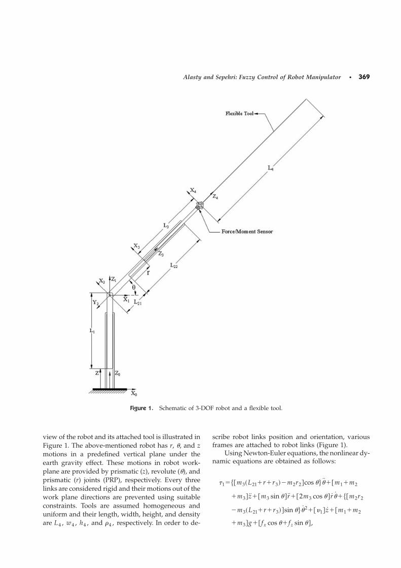
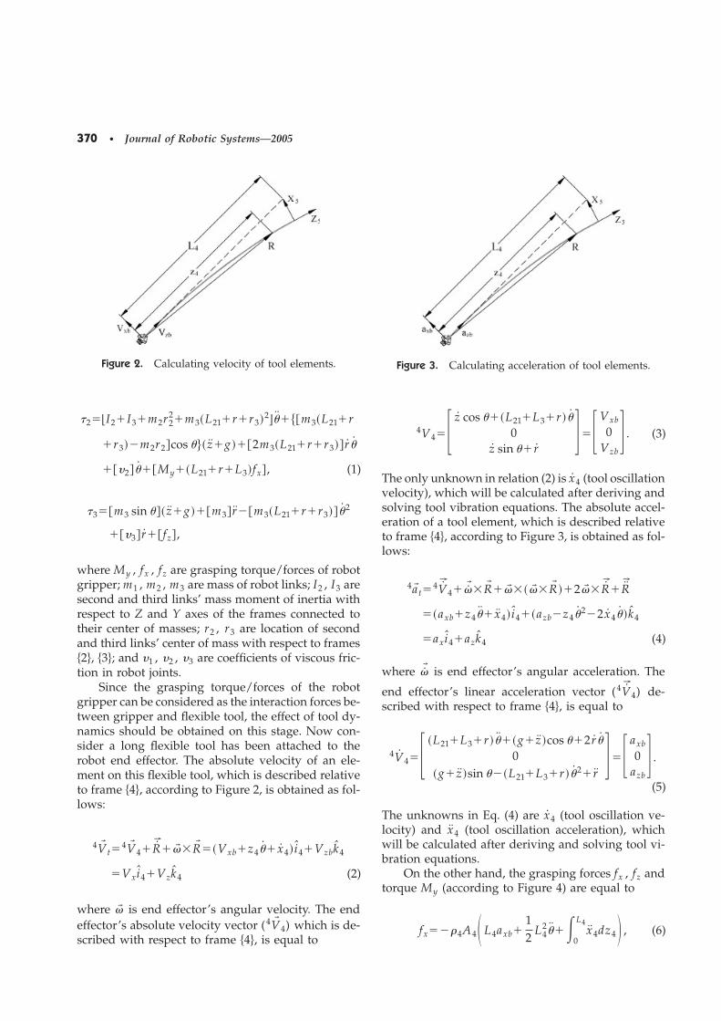
Since the grasping torque/forces of the robotgripper can be considered as the interaction forces be-tween gripper and flexible tool, the effect of tool dy-namics should be obtained on this stage. Now con-sider a long flexible tool has been attached to therobot end effector. The absolute velocity of an ele-ment on this flexible tool, which is described relativeto frame �4, according to Figure 2, is obtained as fol-lows:
4V� t�4V� 4�R���� �R� ��Vxb�z4�� x4� i4�Vzbk4
�Vxi4�Vzk4 (2)
where �� is end effector’s angular velocity. The endeffector’s absolute velocity vector (4V� 4) which is de-scribed with respect to frame �4, is equal to
Figure 2. Calculating velocity of tool elements.
4V4�� z cos ���L21�L3�r ��0
z sin �� r���Vxb
0Vzb
� . (3)
The only unknown in relation (2) is x4 (tool oscillationvelocity), which will be calculated after deriving andsolving tool vibration equations. The absolute accel-eration of a tool element, which is described relativeto frame �4, according to Figure 3, is obtained as fol-lows:
4a� t�4V� 4��� �R� ��� ���� �R� ��2�� �R��R�
��axb�z4�� x4� i4��azb�z4�2�2 x4� �k4
�axi4�azk4 (4)
where �� is end effector’s angular acceleration. The
end effector’s linear acceleration vector (4V� 4) de-scribed with respect to frame �4, is equal to
4V4�� �L21�L3�r ����g� z �cos ��2 r �0
�g� z �sin ���L21�L3�r ��2� r��� axb
0azb
� .
(5)
The unknowns in Eq. (4) are x4 (tool oscillation ve-locity) and x4 (tool oscillation acceleration), whichwill be calculated after deriving and solving tool vi-bration equations.
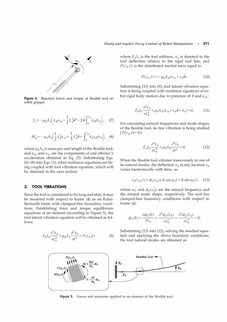
On the other hand, the grasping forces fx , fz andtorque My (according to Figure 4) are equal to
fx���4A4� L4axb�12
L42���
0
L4x4dz4� , (6)
Figure 3. Calculating acceleration of tool elements.
Alasty and Sepehri: Fuzzy Control of Robot Manipulator • 371
fz���4A4� L4azb�12
L42�2�2 ��
0
L4x4dz4� , (7)
My���4A4� 12
L42axb�
13
L43���
0
L4x4z4dz4� , (8)
where �4A4 is mass per unit length of the flexible tool,and axb and azb are the components of end effector’sacceleration obtained in Eq. (5). Substituting Eqs.(6)–(8) into Eqs. (1), robot nonlinear equations are be-ing coupled with tool vibration equation, which willbe obtained in the next section.
3. TOOL VIBRATIONS
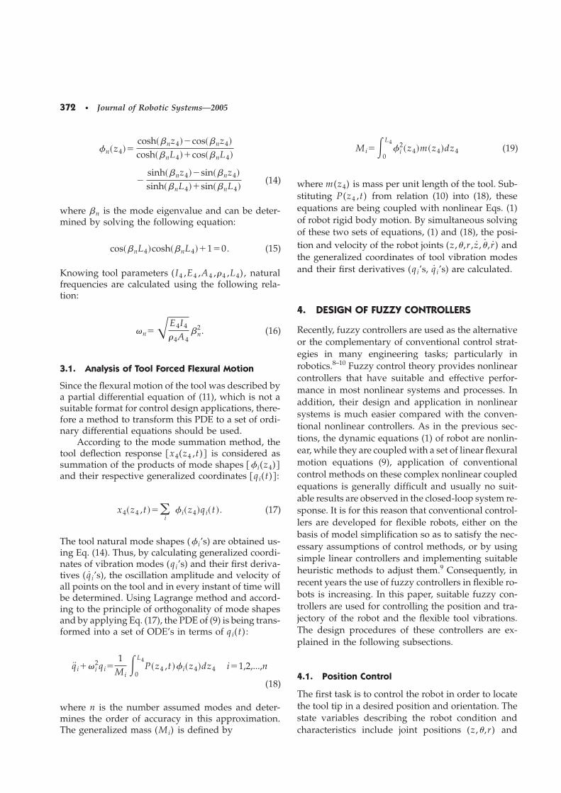
Since the tool is considered to be long and slim, it maybe modeled with respect to frame �4 as an Euler-Bernoulli beam with clamped-free boundary condi-tions. Establishing force and torque equilibriumequations of an element (according to Figure 5), thetool lateral vibration equation will be obtained as fol-lows:
E4I4�4x4
�z44 ��4A4
�2x4
�t2�P�z4 ,t � (9)
Figure 4. Reaction forces and torque of flexible tool onrobot gripper.
where E4I4 is the tool stiffness, x4 is denoted to thetool deflection relative to the rigid tool line, andP(z4 ,t) is the distributed inertial force equal to
P�z4 ,t ����4A4�axb�z4� �. (10)
Substituting (10) into (9), tool lateral vibration equa-tion is being coupled with nonlinear equations of ro-bot rigid body motion due to presence of � and axb :
E4I4�4x4
�z44 ��4A4�axb�z4�� x4��0. (11)
For calculating natural frequencies and mode shapesof the flexible tool, its free vibration is being studied�P(z4 ,t)�0� :
E4I4�4x4
�z44 ��4A4
�2x4
�t2�0. (12)
When the flexible tool vibrates transversely in one ofits natural modes, the deflection x4 at any location z4varies harmonically with time, as
x4�z4 ,t �� n�z4��A cos �nt�B sin �nt � (13)
where �n and n(z4) are the natural frequency andthe related mode shape, respectively. The tool hasclamped-free boundary conditions with respect toframe �4:
n�0 ��� n�0 �
�z4�
�2 n�L4�
�z42 �
�3 n�L4�
�z43 �0.
Substituting (13) into (12), solving the resulted equa-tion and applying the above boundary conditions,the tool natural modes are obtained as
Figure 5. Forces and moments applied to an element of the flexible tool.
372 • Journal of Robotic Systems—2005
n�z4��cosh��nz4��cos��nz4�
cosh��nL4��cos��nL4�
�sinh��nz4��sin��nz4�
sinh��nL4��sin��nL4�(14)
where �n is the mode eigenvalue and can be deter-mined by solving the following equation:
cos��nL4�cosh��nL4��1�0. (15)
Knowing tool parameters (I4 ,E4 ,A4 ,�4 ,L4), naturalfrequencies are calculated using the following rela-tion:
�n��E4I4
�4A4�n
2 . (16)
3.1. Analysis of Tool Forced Flexural Motion
Since the flexural motion of the tool was described bya partial differential equation of (11), which is not asuitable format for control design applications, there-fore a method to transform this PDE to a set of ordi-nary differential equations should be used.
According to the mode summation method, thetool deflection response �x4(z4 ,t)� is considered assummation of the products of mode shapes � i(z4)�and their respective generalized coordinates �qi(t)� :
x4�z4 ,t ���i
i�z4�qi�t �. (17)
The tool natural mode shapes ( i’s) are obtained us-ing Eq. (14). Thus, by calculating generalized coordi-nates of vibration modes (qi’s) and their first deriva-tives ( q i’s), the oscillation amplitude and velocity ofall points on the tool and in every instant of time willbe determined. Using Lagrange method and accord-ing to the principle of orthogonality of mode shapesand by applying Eq. (17), the PDE of (9) is being trans-formed into a set of ODE’s in terms of qi(t):
q i�� i2qi�
1Mi
�0
L4P�z4 ,t � i�z4�dz4 i�1,2,...,n
(18)
where n is the number assumed modes and deter-mines the order of accuracy in this approximation.The generalized mass (Mi) is defined by
Mi��0
L4 i
2�z4�m�z4�dz4 (19)
where m(z4) is mass per unit length of the tool. Sub-stituting P(z4 ,t) from relation (10) into (18), theseequations are being coupled with nonlinear Eqs. (1)of robot rigid body motion. By simultaneous solvingof these two sets of equations, (1) and (18), the posi-tion and velocity of the robot joints (z ,� ,r , z , � , r) andthe generalized coordinates of tool vibration modesand their first derivatives (qi’s, q i’s) are calculated.
4. DESIGN OF FUZZY CONTROLLERS
Recently, fuzzy controllers are used as the alternativeor the complementary of conventional control strat-egies in many engineering tasks; particularly inrobotics.8–10 Fuzzy control theory provides nonlinearcontrollers that have suitable and effective perfor-mance in most nonlinear systems and processes. Inaddition, their design and application in nonlinearsystems is much easier compared with the conven-tional nonlinear controllers. As in the previous sec-tions, the dynamic equations (1) of robot are nonlin-ear, while they are coupled with a set of linear flexuralmotion equations (9), application of conventionalcontrol methods on these complex nonlinear coupledequations is generally difficult and usually no suit-able results are observed in the closed-loop system re-sponse. It is for this reason that conventional control-lers are developed for flexible robots, either on thebasis of model simplification so as to satisfy the nec-essary assumptions of control methods, or by usingsimple linear controllers and implementing suitableheuristic methods to adjust them.9 Consequently, inrecent years the use of fuzzy controllers in flexible ro-bots is increasing. In this paper, suitable fuzzy con-trollers are used for controlling the position and tra-jectory of the robot and the flexible tool vibrations.The design procedures of these controllers are ex-plained in the following subsections.
4.1. Position Control
The first task is to control the robot in order to locatethe tool tip in a desired position and orientation. Thestate variables describing the robot condition andcharacteristics include joint positions (z ,� ,r) and
Alasty and Sepehri: Fuzzy Control of Robot Manipulator • 373
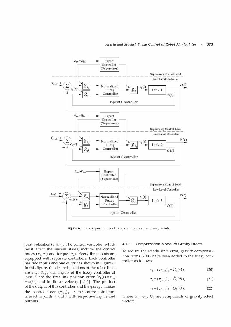
Figure 6. Fuzzy position control system with supervisory levels.
joint velocities ( z , � , r). The control variables, whichmust affect the system states, include the controlforces (�1 ,�3) and torque (�2). Every three joints areequipped with separate controllers. Each controllerhas two inputs and one output as shown in Figure 6.In this figure, the desired positions of the robot linksare zref , �ref , rref . Inputs of the fuzzy controller ofjoint Z are the first link position error �e1(t)�zref�z(t)� and its linear velocity � z(t)� . The productof the output of this controller and the gain g�1
makesthe control force (� fuz)1 . Same control structureis used in joints � and r with respective inputs andoutputs.
4.1.1. Compensation Model of Gravity Effects
To reduce the steady state error, gravity compensa-tion terms G(�) have been added to the fuzzy con-troller as follows:
�1��� fuzz�1�G1���, (20)
�2��� fuzz�2�G2���, (21)
�3��� fuzz�3�G3���, (22)
where G1 , G2 , G3 are components of gravity effectvector:
374 • Journal of Robotic Systems—2005
G����� g�m1�m2�m3�m4�
�m3�r3�L21�r ��m2r2�m4�L21�L3�r� z/2��g cos ��m3�m4�g sin �
� . (23)
Here z�L4��Xstat�x4(L4 ,t)�tan � and ��40�Xstat�x4(L4 ,t)�/(3L4). The static deflection and slope ofthe tool tip are denoted by Xstat and �, respectively.For simplification purposes, illustration of G1 , G2 ,G3 in Figure 6 has been ignored and fuzzy controllersoutputs are shown as �1 , �2 , �3 .
4.1.2. Supervisory Control
The input and output universes of discourse of thefuzzy controller are normalized on the range of[−1,1]. The gains ge1
, ge2, ge3
and gz , g � , gr are usedto map the actual inputs of the fuzzy systems to thenormalized universe of discourse [−1,1] and arecalled ‘‘normalization gains.’’ Similarly g�1
, g�2, g�3
are the output gains to scale the output of the con-trollers. The values of input and output gains dependon the robot initial and final conditions. It means thatfor specified values of joint position errors (e1 ,e2 ,e3),these gains are determined in order to minimize theovershoot and to have the same settling time in all thejoint variables. Then for other values of joint positionerrors, and at the beginning of the motion, these gainsare calculated by supervisory control levels so thatevery three joint variables reach its final value simul-taneously. The supervisory control level assures over-shoot reduction, equal settling time in all three joints,and prevents excitation of tool vibration modes. Inabsence of supervisory control, simulation resultshave shown unstable responses to some commandconditions. These controllers change the width of uni-verses of discourse by changing the input and outputgain factors.9 The calculation steps in the supervisoryalgorithm are as follows.
• Parameters t1 , t2 and t3 are defined as follows:
� t1��zref�zini�
0.2, t2�
��ref�� ini�40
, t3��rref�rini�
0.2.
(24)
The denominators 0.2m , 40°, 0.2m are criterion valuesselected for �z , ��, and �r , respectively, in order toachieve equal settling time of approximately 1 secondin all three joint variables. In the other words for thesevalues of �z , ��, and �r , the three joint variables
reach the target position in unit time. After calculat-ing t i’s, the following rule is considered:
Rule : If t i�0.01s⇒t i�0.01s . (25)
• Now the maximum value of t i’s is selected andrule (27) is applied as
� tmax�max�t1 ,t2 ,t3�, (26)
Rule : If tmax�0.25s⇒tmax�0.25s . (27)
• Normalized t i’s are defined as
� s1�t1
tmax, s2�
t2
tmax, s3�
t3
tmax. (28)
Then the following rule is considered for si’s:
Rule : If si�0.01s⇒si�0.01s . (29)
• At this stage the instantaneous input and out-put gain values are determined according to the robotcondition and using the following relations:
g�1�
�g�1�ref
t1, gz�
�gz�ref
s1, ge1
��ge1
�ref
t1,
g�2�
�g�2�ref
t2, g ��
�g � �ref
s2, ge2
��ge2
�ref
t2,
(30)
g�3�
�g�3�ref
t3, gr�
�gr�ref
s3, ge3
��ge3
�ref
t3
where (ge1)ref , (ge2
)ref , (ge3)ref , (gz)ref , (g �)ref ,
(gr)ref , (g�1)ref , (g�2
)ref , (g�3)ref are the selected input
and output gain values for reference conditions: �z�0.2m, ��=40°, �r�0.2m . The reason of using s1 , s2 ,s3 , (si�1) in calculation of gz , g � , gr , is to make the
Alasty and Sepehri: Fuzzy Control of Robot Manipulator • 375
universe of discourse width of the joint velocities lessthan or equal to those of reference conditions.
4.1.3. Rule Base
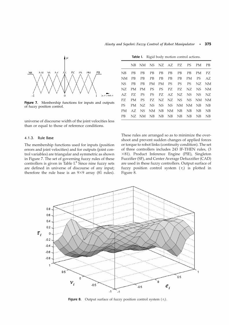
The membership functions used for inputs (positionerrors and joint velocities) and for outputs (joint con-trol variables) are triangular and symmetric as shownin Figure 7. The set of governing fuzzy rules of thesecontrollers is given in Table I.8 Since nine fuzzy setsare defined in universe of discourse of any input;therefore the rule base is an 9�9 array (81 rules).
Figure 7. Membership functions for inputs and outputsof fuzzy position control.
These rules are arranged so as to minimize the over-shoot and prevent sudden changes of applied forcesor torque to robot links (continuity condition). The setof three controllers includes 243 IF-THEN rules, (3�81). Product Inference Engine (PIE), SingletonFuzzifier (SF), and Center Average Defuzzifier (CAD)are used in these fuzzy controllers. Output surface offuzzy position control system (� i) is plotted inFigure 8.
Table I. Rigid body motion control actions.
NB NM NS NZ AZ PZ PS PM PB
NB PB PB PB PB PB PB PB PM PZ
NM PB PB PB PB PB PB PM PS AZ
NS PB PB PM PM PS PS PS NZ NM
NZ PM PM PS PS PZ PZ NZ NS NM
AZ PZ PS PS PZ AZ NZ NS NS NZ
PZ PM PS PZ NZ NZ NS NS NM NM
PS PM NZ NS NS NS NM NM NB NB
PM AZ NS NM NB NM NB NB NB NB
PB NZ NM NB NB NB NB NB NB NB
Figure 8. Output surface of fuzzy position control system (� i).
376 • Journal of Robotic Systems—2005
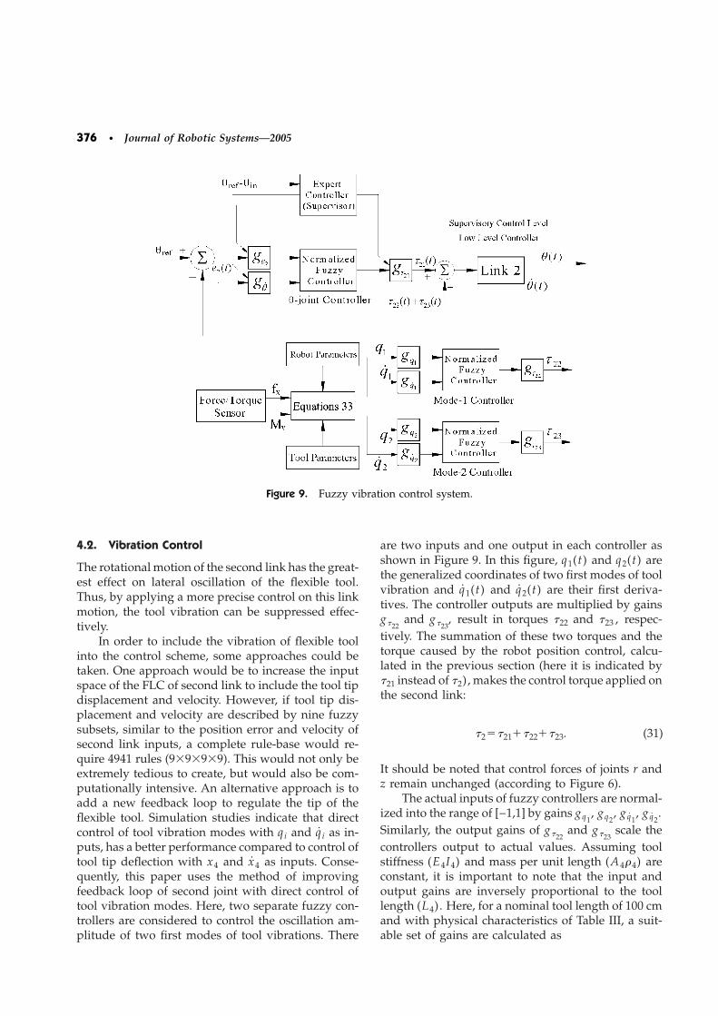
Figure 9. Fuzzy vibration control system.
4.2. Vibration Control
The rotational motion of the second link has the great-est effect on lateral oscillation of the flexible tool.Thus, by applying a more precise control on this linkmotion, the tool vibration can be suppressed effec-tively.
In order to include the vibration of flexible toolinto the control scheme, some approaches could betaken. One approach would be to increase the inputspace of the FLC of second link to include the tool tipdisplacement and velocity. However, if tool tip dis-placement and velocity are described by nine fuzzysubsets, similar to the position error and velocity ofsecond link inputs, a complete rule-base would re-quire 4941 rules (9�9�9�9). This would not only beextremely tedious to create, but would also be com-putationally intensive. An alternative approach is toadd a new feedback loop to regulate the tip of theflexible tool. Simulation studies indicate that directcontrol of tool vibration modes with qi and q i as in-puts, has a better performance compared to control oftool tip deflection with x4 and x4 as inputs. Conse-quently, this paper uses the method of improvingfeedback loop of second joint with direct control oftool vibration modes. Here, two separate fuzzy con-trollers are considered to control the oscillation am-plitude of two first modes of tool vibrations. There
are two inputs and one output in each controller asshown in Figure 9. In this figure, q1(t) and q2(t) arethe generalized coordinates of two first modes of toolvibration and q1(t) and q2(t) are their first deriva-tives. The controller outputs are multiplied by gainsg�22
and g�23, result in torques �22 and �23 , respec-
tively. The summation of these two torques and thetorque caused by the robot position control, calcu-lated in the previous section (here it is indicated by�21 instead of �2), makes the control torque applied onthe second link:
�2��21��22��23. (31)
It should be noted that control forces of joints r andz remain unchanged (according to Figure 6).
The actual inputs of fuzzy controllers are normal-ized into the range of [−1,1] by gains gq1
, gq2, gq1
, gq2.
Similarly, the output gains of g�22and g�23
scale thecontrollers output to actual values. Assuming toolstiffness (E4I4) and mass per unit length (A4�4) areconstant, it is important to note that the input andoutput gains are inversely proportional to the toollength (L4). Here, for a nominal tool length of 100 cmand with physical characteristics of Table III, a suit-able set of gains are calculated as
Alasty and Sepehri: Fuzzy Control of Robot Manipulator • 377
gq1�5, gq2
�10, gq1�0.16, gq2
�0.83,
g�22�300, g�23
�300.
For other tool lengths the gains will be modified ac-cording to the mentioned rule.
4.2.1. Rule Base
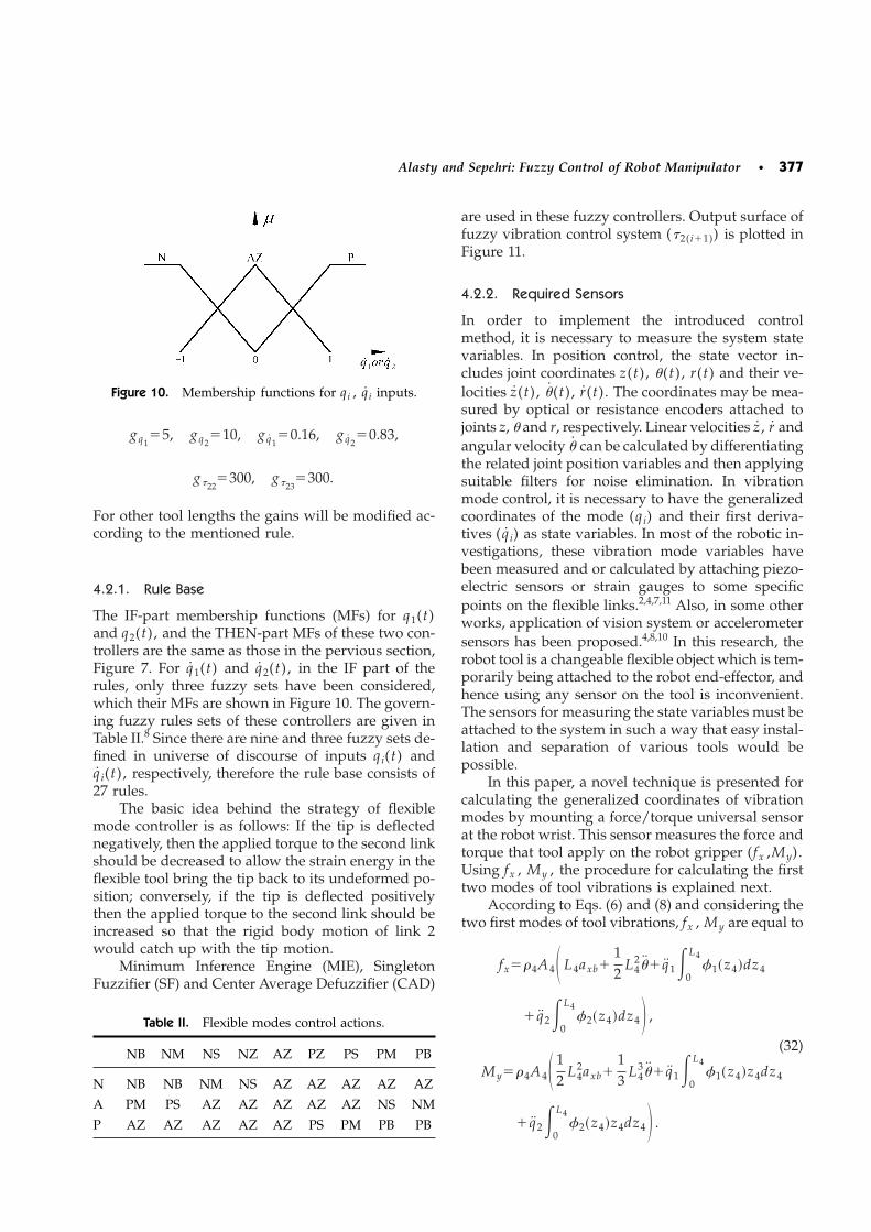
The IF-part membership functions (MFs) for q1(t)and q2(t), and the THEN-part MFs of these two con-trollers are the same as those in the pervious section,Figure 7. For q1(t) and q2(t), in the IF part of therules, only three fuzzy sets have been considered,which their MFs are shown in Figure 10. The govern-ing fuzzy rules sets of these controllers are given inTable II.8 Since there are nine and three fuzzy sets de-fined in universe of discourse of inputs qi(t) andq i(t), respectively, therefore the rule base consists of27 rules.
The basic idea behind the strategy of flexiblemode controller is as follows: If the tip is deflectednegatively, then the applied torque to the second linkshould be decreased to allow the strain energy in theflexible tool bring the tip back to its undeformed po-sition; conversely, if the tip is deflected positivelythen the applied torque to the second link should beincreased so that the rigid body motion of link 2would catch up with the tip motion.
Minimum Inference Engine (MIE), SingletonFuzzifier (SF) and Center Average Defuzzifier (CAD)
Figure 10. Membership functions for qi , q i inputs.
Table II. Flexible modes control actions.
NB NM NS NZ AZ PZ PS PM PB
N NB NB NM NS AZ AZ AZ AZ AZ
A PM PS AZ AZ AZ AZ AZ NS NM
P AZ AZ AZ AZ AZ PS PM PB PB
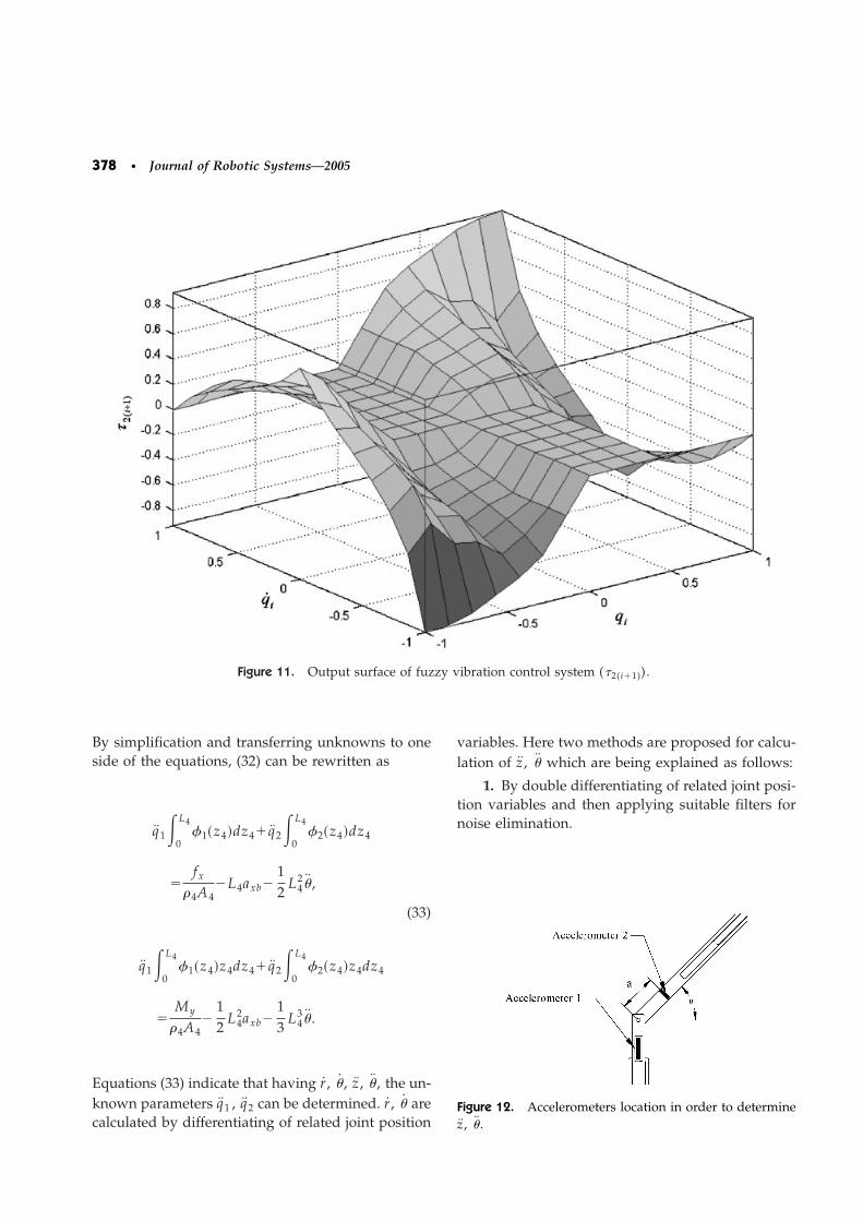
are used in these fuzzy controllers. Output surface offuzzy vibration control system (�2(i�1)) is plotted inFigure 11.
4.2.2. Required Sensors
In order to implement the introduced controlmethod, it is necessary to measure the system statevariables. In position control, the state vector in-cludes joint coordinates z(t), �(t), r(t) and their ve-locities z(t), �(t), r(t). The coordinates may be mea-sured by optical or resistance encoders attached tojoints z, � and r, respectively. Linear velocities z , r andangular velocity � can be calculated by differentiatingthe related joint position variables and then applyingsuitable filters for noise elimination. In vibrationmode control, it is necessary to have the generalizedcoordinates of the mode (qi) and their first deriva-tives ( q i) as state variables. In most of the robotic in-vestigations, these vibration mode variables havebeen measured and or calculated by attaching piezo-electric sensors or strain gauges to some specificpoints on the flexible links.2,4,7,11 Also, in some otherworks, application of vision system or accelerometersensors has been proposed.4,8,10 In this research, therobot tool is a changeable flexible object which is tem-porarily being attached to the robot end-effector, andhence using any sensor on the tool is inconvenient.The sensors for measuring the state variables must beattached to the system in such a way that easy instal-lation and separation of various tools would bepossible.
In this paper, a novel technique is presented forcalculating the generalized coordinates of vibrationmodes by mounting a force/torque universal sensorat the robot wrist. This sensor measures the force andtorque that tool apply on the robot gripper (fx ,My).Using fx , My , the procedure for calculating the firsttwo modes of tool vibrations is explained next.
According to Eqs. (6) and (8) and considering thetwo first modes of tool vibrations, fx , My are equal to
fx��4A4� L4axb�12
L42�� q1�
0
L4 1�z4�dz4
� q2�0
L4 2�z4�dz4� ,
(32)
My��4A4� 12
L42axb�
13
L43�� q1�
0
L4 1�z4�z4dz4
� q2�0
L4 2�z4�z4dz4� .
378 • Journal of Robotic Systems—2005
Figure 11. Output surface of fuzzy vibration control system (�2(i�1)).
By simplification and transferring unknowns to oneside of the equations, (32) can be rewritten as
q1�0
L4 1�z4�dz4� q2�
0
L4 2�z4�dz4
�fx
�4A4�L4axb�
12
L42� ,
(33)
q1�0
L4 1�z4�z4dz4� q2�
0
L4 2�z4�z4dz4
�My
�4A4�
12
L42axb�
13
L43� .
Equations (33) indicate that having r , � , z , � , the un-known parameters q1 , q2 can be determined. r , � arecalculated by differentiating of related joint position
variables. Here two methods are proposed for calcu-lation of z , � which are being explained as follows:
1. By double differentiating of related joint posi-tion variables and then applying suitable filters fornoise elimination.
Figure 12. Accelerometers location in order to determinez , � .
Alasty and Sepehri: Fuzzy Control of Robot Manipulator • 379
2. By using two accelerometers, first of whichmeasures z by attaching to first link and second ismounted on second link and measures the accelera-
Table III. Robot data.
Description Notation Value Unit
Length of link 1 L1 0.5 m
Length of first part in link 2 L21 0.2 m
Length of second part in link 2 L22 0.5 m
Length of link 3 L3 0.5 m
Width of link 1 w1 0.04 m
Width of first part in link 2 w21 0.04 m
Width of second part in link 2 w22 0.01 m
Width of link 3 w3 0.02 m
Thickness of the link 1 h1 0.02 m
Thickness of the link 2 h2 0.02 m
Thickness of the link 3 h3 0.02 m
Mass density of link 1 �1 7860 Kg/m3
Mass density of link 2 �2 7860 Kg/m3
Mass density of link 3 �3 7860 Kg/m3
tion in the direction perpendicular to this link. Figure12 shows the locations of these two accelerometers.According to this figure the output of the accelerom-eters are related to z , � as
Output of Accelerometer 1� z , (34)
Output of Accelerometer 2� z cos ��a � , (35)
where a is the distance between the second acceler-ometer and central point of joint �.
Solving relations (34) and (35) for � , the secondlink angular acceleration is calculated as
Table IV. Flexible tool data.
Description Notation Value Unit
Length L4 Arbitrary m
Width w4 0.005 m
Thickness h4 0.02 m
Mass density �4 2712.6 Kg/m3
Modulus of elasticity E4 7.1�1010 Pa
���Output of Accelerometer 2 ���Output of Accelerometer 1 �0 cos �
a. (36)
Consequently the values of q1 , q2 are calculated bysolving Eqs. (33). By double repetitive integration, thevalues of q1 , q2 and q1 , q2 are determined too.
4.2.3. Estimation of Robot Tool Length
After mounting a new tool on the robot and prior toperforming any task, the robot moves to a few dif-ferent positions by changing the second link angle. Ina complete static situation the torque/force sensormeasures the values of fx and/or My . In completestatic situation ( z� �� r� �� x4�0), the measuredforce components fx , My are equal to
fx��4A4L4g cos � , (37)
My�12
�4A4L42g cos � . (38)
Both equations give the value of L4 :
L4�fx
�4A4g cos ��� 2My
�4A4g cos ��1/2
�2My
fx. (39)
Thus, if �4A4 (the mass per unit length of the tool) isassumed to be known, the tool length (L4) can be ob-tained by interpolation between calculated values fora few different angles (�).
5. SIMULATION RESULTS
The physical characteristics assumed in simulation ofrobot and flexible tool set are given in Tables III andIV. The five first frequencies of the flexible tool (with

380 • Journal of Robotic Systems—2005
length 100 cm and physical parameters of Table IV)can be obtained as
��rad/sec��25.96,162.71,455.60,892.78,1475.85.
In numerical simulation, tool vibration is approxi-mated using these values. In order to study the per-formance of vibration mode controller and its effecton oscillation reduction, three following conditionsare considered:
1. The tool is assumed to be rigid. In this case,tool vibration is ignored in simulation, and positionfuzzy control (Figure 6) is applied on the robot.
2. The tool is flexible but only the position fuzzycontrol system is active (Figure 6).
Figure 13. Position variable of first joint (z).
Figure 14. Position variable of second joint (�).
3. The tool is flexible and both systems, positionfuzzy control and fuzzy control of the two first vibra-tion modes, are active (Figure 9).
(zini�0, � ini�0, rini�0) and (zref�0.3285m , �ref�30° , rref�0.3029m) are assumed as initial and finalconditions, respectively. These final conditions locatethe tool tip at the position (Px�1.766m , Pz�1.8m).Remind that Px and Pz are the positions of tool tiprelative to frame �0 and in directions of X0 and Z0axes, respectively.
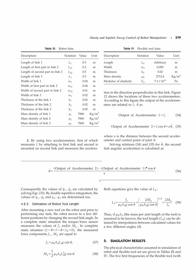
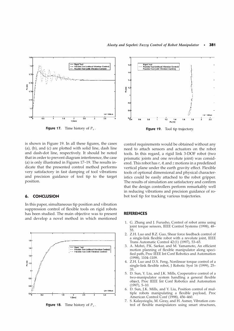
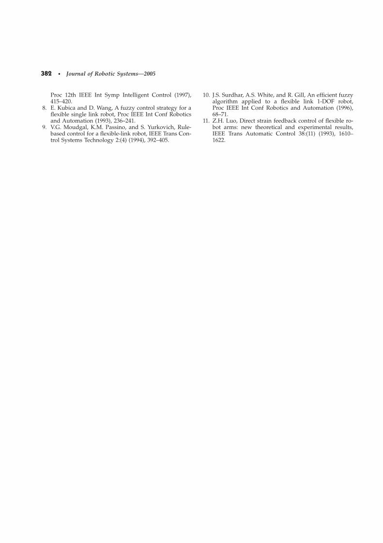
The values of z, �, and r (the position variables ofthree links of the robot) versus time are shown in Fig-ures 13–15, respectively. Figure 16 shows oscillationamplitude of tool tip (xlr) versus time. Figures 17and 18 show values of Px and Pz versus time, respec-tively. The trajectory that tool tip tracks in workplane
Figure 15. Position variable of third joint (r).
Figure 16. Oscillations amplitude of the tool tip (xlr).
Alasty and Sepehri: Fuzzy Control of Robot Manipulator • 381
is shown in Figure 19. In all these figures, the cases(a), (b), and (c) are plotted with solid line, dash lineand dash-dot line, respectively. It should be notedthat in order to prevent diagram interference, the case(a) is only illustrated in Figures 17–19. The results in-dicate that the presented control method performsvery satisfactory in fast damping of tool vibrationsand precision guidance of tool tip to the targetposition.
6. CONCLUSION
In this paper, simultaneous tip position and vibrationsuppression control of flexible tools on rigid robotshas been studied. The main objective was to presentand develop a novel method in which mentioned
Figure 17. Time history of Px .
Figure 18. Time history of Pz .
control requirements would be obtained without anyneed to attach sensors and actuators on the robottools. In this regard, a rigid link 3-DOF robot (twoprismatic joints and one revolute joint) was consid-ered. This robot has r, �, and z motions in a predefinedvertical plane under the earth gravity effect. Flexibletools of optional dimensional and physical character-istics could be easily attached to the robot gripper.The results of simulation are satisfactory and confirmthat the design controllers perform remarkably wellin reducing vibrations and precision guidance of ro-bot tool tip for tracking various trajectories.
REFERENCES
1. G. Zhang and J. Furusho, Control of robot arms usingjoint torque sensors, IEEE Control Systems (1998), 48–55.
2. Z.H. Luo and B.Z. Guo, Shear force feedback control ofa single-link flexible robot with a revolute joint, IEEETrans Automatic Control 42:(1) (1997), 53–65.
3. A. Mohri, P.K. Sarkar, and M. Yamamoto, An efficientmotion planning of flexible manipulator along speci-fied path, Proc IEEE Int Conf Robotics and Automation(1998), 1104–1109.
4. Z.H. Luo and D.X. Feng, Nonlinear torque control of asingle-link flexible robot, J Robotic Syst 16 (1999), 25–35.
5. D. Sun, Y. Liu, and J.K. Mills, Cooperative control of atwo-manipulator system handling a general flexibleobject, Proc IEEE Int Conf Robotics and Automation(1997), 5–10.
6. D. Sun, J.K. Mills, and Y. Liu, Position control of mul-tiple robots manipulating a flexible payload, ProcAmerican Control Conf (1998), 456–460.
7. S. Kalayeioglu, M. Giray, and H. Asmer, Vibration con-trol of flexible manipulators using smart structures,
Figure 19. Tool tip trajectory.
382 • Journal of Robotic Systems—2005
Proc 12th IEEE Int Symp Intelligent Control (1997),415–420.
8. E. Kubica and D. Wang, A fuzzy control strategy for aflexible single link robot, Proc IEEE Int Conf Roboticsand Automation (1993), 236–241.
9. V.G. Moudgal, K.M. Passino, and S. Yurkovich, Rule-based control for a flexible-link robot, IEEE Trans Con-trol Systems Technology 2:(4) (1994), 392–405.
10. J.S. Surdhar, A.S. White, and R. Gill, An efficient fuzzyalgorithm applied to a flexible link 1-DOF robot,Proc IEEE Int Conf Robotics and Automation (1996),68–71.
11. Z.H. Luo, Direct strain feedback control of flexible ro-bot arms: new theoretical and experimental results,IEEE Trans Automatic Control 38:(11) (1993), 1610–1622.