Gauge Based Collision Detection Mechanism for a new Three-degree-of-freedom Flexible Robot
6
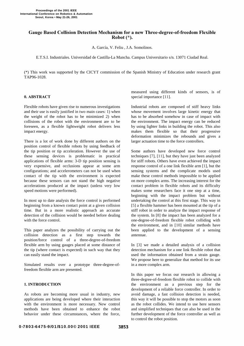
*DXJH%DVHG&ROOLVLRQ’HWHFWLRQ0HFKDQLVPIRUDQHZ7KUHHGHJUHHRIIUHHGRP)OH[LEOH 5RERW A. García, V. Feliu , J.A. Somolinos. E.T.S.I. Industriales. Universidad de Castilla-La Mancha. Campus Universitario s/n. 13071 Ciudad Real. (*) This work was supported by the CICYT commission of the Spanish Ministry of Education under research grant TAP96-1028. $%675$&7 Flexible robots have given rise to numerous investigations and their use is easily justified in two main cases: 1) when the weight of the robot has to be minimized 2) when collisions of the robot with the environment are to be foreseen, as a flexible lightweight robot delivers less impact energy. There is a lot of work done by different authors on the position control of flexible robots by using feedback of the tip position or tip acceleration. However the use of these sensing devices is problematic in practical applications of flexible arms: 3-D tip position sensing is very expensive, and occlusions appear at some arm configurations; and accelerometers can not be used when contact of the tip with the environment is expected because these sensors can not stand the high negative accelerations produced at the impact (unless very low speed motions were performed). In most up to date analysis the force control is performed beginning from a known contact point at a given collision time. But in a more realistic approach an accurate detection of the collision would be needed before dealing with the force control. This paper analyzes the possibility of carrying out the collision detection as a first step towards the position/force control of a three-degree-of-freedom flexible arm by using gauges placed at some distance of the tip (where contact is expected) in such way that they can easily stand the impact. Simulated results over a prototype three-degree-of- freedom flexible arm are presented. ,1752’8&7,21 As robots are becoming more usual in industry, new applications are being developed where their interaction with the environment is more necessary. New control methods have been obtained to enhance the robot behavior under these circumstances, where the force, measured using different kinds of sensors, is of special importance [11]. Industrial robots are composed of stiff heavy links whose movement involves large kinetic energy that has to be absorbed somehow in case of impact with the environment. The impact energy can be reduced by using lighter links in building the robot. This also makes them flexible so that their progressive deformation minimizes the rebounds and gives a larger actuation time to the force controllers. Some authors have developed new force control techniques [7], [11], but they have just been analyzed for stiff robots. Others have even achieved the impact response control of a one link flexible arm [1], but the sensing systems and the complicate models used make these control methods impossible to be applied on more complex arms. The increasing interest for the contact problem in flexible robots and its difficulty makes some researchers face it one step at a time, beginning with the impact problem but without undertaking the control at this first stage. This way in [5] a flexible hammer has been mounted at the tip of a stiff robot in order to analyze the impact response of the system. In [8] the impact has been analyzed for a one-degree-of-freedom flexible robot colliding with the environment, and in [10] similar methods have been applied to the development of a sensing antennae. In [3] we made a detailed analysis of a collision detection mechanism for a one link flexible robot that used the information obtained from a strain gauge. We propose here to generalize that method for its use in a more complex arm. In this paper we focus our research in allowing a three-degree-of-freedom flexible robot to collide with the environment as a previous step for the development of a reliable force controller. In order to avoid damage, a fast collision detection is needed, this way it will be possible to stop the motors as soon as the robot collides. We intend to use here sensors and simplified techniques that can also be used in the further development of the force controller as well as to control the robot position. 0-7803-6475-9/01/$10.00© 2001 IEEE Proceedings of the 2001 IEEE International Conference on Robotics & Automation Seoul, Korea • May 21-26, 2001
-
Upload
independent -
Category
Documents
-
view
0 -
download
0
Transcript of Gauge Based Collision Detection Mechanism for a new Three-degree-of-freedom Flexible Robot
*DXJH�%DVHG�&ROOLVLRQ�'HWHFWLRQ�0HFKDQLVP�IRU�D�QHZ�7KUHH�GHJUHH�RI�IUHHGRP�)OH[LEOH5RERW�� ��
A. García, V. Feliu , J.A. Somolinos.
E.T.S.I. Industriales. Universidad de Castilla-La Mancha. Campus Universitario s/n. 13071 Ciudad Real.
(*) This work was supported by the CICYT commission of the Spanish Ministry of Education under research grantTAP96-1028.
���$%675$&7
Flexible robots have given rise to numerous investigationsand their use is easily justified in two main cases: 1) whenthe weight of the robot has to be minimized 2) whencollisions of the robot with the environment are to beforeseen, as a flexible lightweight robot delivers lessimpact energy.
There is a lot of work done by different authors on theposition control of flexible robots by using feedback ofthe tip position or tip acceleration. However the use ofthese sensing devices is problematic in practicalapplications of flexible arms: 3-D tip position sensing isvery expensive, and occlusions appear at some armconfigurations; and accelerometers can not be used whencontact of the tip with the environment is expectedbecause these sensors can not stand the high negativeaccelerations produced at the impact (unless very lowspeed motions were performed).
In most up to date analysis the force control is performedbeginning from a known contact point at a given collisiontime. But in a more realistic approach an accuratedetection of the collision would be needed before dealingwith the force control.
This paper analyzes the possibility of carrying out thecollision detection as a first step towards theposition/force control of a three-degree-of-freedomflexible arm by using gauges placed at some distance ofthe tip (where contact is expected) in such way that theycan easily stand the impact.
Simulated results over a prototype three-degree-of-freedom flexible arm are presented.
���,1752'8&7,21
As robots are becoming more usual in industry, newapplications are being developed where their interactionwith the environment is more necessary. New controlmethods have been obtained to enhance the robotbehavior under these circumstances, where the force,
measured using different kinds of sensors, is ofspecial importance [11].
Industrial robots are composed of stiff heavy linkswhose movement involves large kinetic energy thathas to be absorbed somehow in case of impact withthe environment. The impact energy can be reducedby using lighter links in building the robot. This alsomakes them flexible so that their progressivedeformation minimizes the rebounds and gives alarger actuation time to the force controllers.
Some authors have developed new force controltechniques [7], [11], but they have just been analyzedfor stiff robots. Others have even achieved the impactresponse control of a one link flexible arm [1], but thesensing systems and the complicate models usedmake these control methods impossible to be appliedon more complex arms. The increasing interest for thecontact problem in flexible robots and its difficultymakes some researchers face it one step at a time,beginning with the impact problem but withoutundertaking the control at this first stage. This way in[5] a flexible hammer has been mounted at the tip of astiff robot in order to analyze the impact response ofthe system. In [8] the impact has been analyzed for aone-degree-of-freedom flexible robot colliding withthe environment, and in [10] similar methods havebeen applied to the development of a sensingantennae.
In [3] we made a detailed analysis of a collisiondetection mechanism for a one link flexible robot thatused the information obtained from a strain gauge.We propose here to generalize that method for its usein a more complex arm.
In this paper we focus our research in allowing athree-degree-of-freedom flexible robot to collide withthe environment as a previous step for thedevelopment of a reliable force controller. In order toavoid damage, a fast collision detection is needed,this way it will be possible to stop the motors as soonas the robot collides. We intend to use here sensorsand simplified techniques that can also be used in thefurther development of the force controller as well asto control the robot position.
0-7803-6475-9/01/$10.00© 2001 IEEE
Proceedings of the 2001 IEEE International Conference on Robotics & Automation
Seoul, Korea • May 21-26, 2001
ralph
3853
In Section 2 a dynamic description of the robot used hasbeen carried out. In Section 3 a model for the collision hasbeen established. In Section 4 the collision detectionmechanism is discussed and an application example isproposed, and some conclusions are stated in Section 5.
��� '<1$0,&� '(6&5,37,21� 2)� 7+(352727<3(
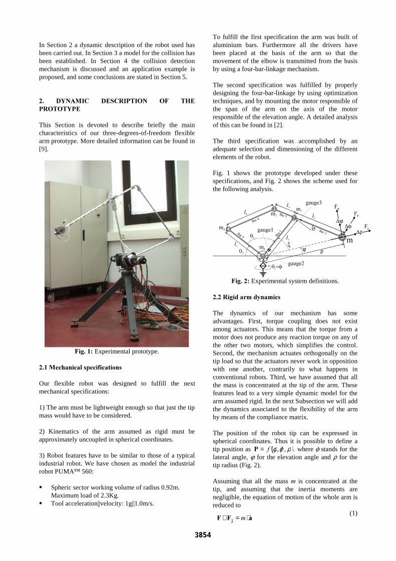
This Section is devoted to describe briefly the maincharacteristics of our three-degrees-of-freedom flexiblearm prototype. More detailed information can be found in[9].
)LJ�����Experimental prototype.
����0HFKDQLFDO�VSHFLILFDWLRQV
Our flexible robot was designed to fulfill the nextmechanical specifications:
1) The arm must be lightweight enough so that just the tipmass would have to be considered.
2) Kinematics of the arm assumed as rigid must beapproximately uncoupled in spherical coordinates.
3) Robot features have to be similar to those of a typicalindustrial robot. We have chosen as model the industrialrobot PUMA¹ 560:
� Spheric sector working volume of radius 0.92m.Maximum load of 2.3Kg.
� Tool acceleration||velocity: 1g||1.0m/s.
To fulfill the first specification the arm was built ofaluminium bars. Furthermore all the drivers havebeen placed at the basis of the arm so that themovement of the elbow is transmitted from the basisby using a four-bar-linkage mechanism.
The second specification was fulfilled by properlydesigning the four-bar-linkage by using optimizationtechniques, and by mounting the motor responsible ofthe span of the arm on the axis of the motorresponsible of the elevation angle. A detailed analysisof this can be found in [2].
The third specification was accomplished by anadequate selection and dimensioning of the differentelements of the robot.
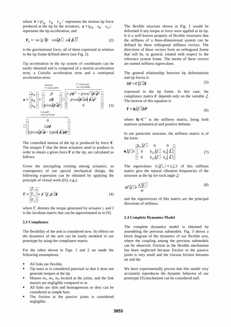
Fig. 1 shows the prototype developed under thesespecifications, and Fig. 2 shows the scheme used forthe following analysis.
)LJ���� Experimental system definitions.
����5LJLG�DUP�G\QDPLFV
The dynamics of our mechanism has someadvantages. First, torque coupling does not existamong actuators. This means that the torque from amotor does not produce any reaction torque on any ofthe other two motors, which simplifies the control.Second, the mechanism actuates orthogonally on thetip load so that the actuators never work in oppositionwith one another, contrarily to what happens inconventional robots. Third, we have assumed that allthe mass is concentrated at the tip of the arm. Thesefeatures lead to a very simple dynamic model for thearm assumed rigid. In the next Subsection we will addthe dynamics associated to the flexibility of the armby means of the compliance matrix.
The position of the robot tip can be expressed inspherical coordinates. Thus it is possible to define atip position as ( )ρϕφ ,,I=3 where f stands for thelateral angle, j for the elevation angle and r for thetip radius (Fig. 2).
Assuming that all the mass P is concentrated at thetip, and assuming that the inertia moments arenegligible, the equation of motion of the whole arm isreduced to
(1)D)) ⋅=+ P
J
ralph
3854
where ( )7))) ρϕφ=) represents the motion tip forceproduced at the tip by the actuators, ( )7DDD ρϕφ=Drepresents the tip acceleration, and
(2)
is the gravitational force, all of them expressed in relationto the tip frame defined above (see Fig. 2).
Tip acceleration in the tip system of coordinates can beeasily obtained and is composed of a motion accelerationterm, a Coriolis acceleration term and a centripetalacceleration term:
(3)
The controlled motion of the tip is produced by force ).The torques G that the three actuators need to produce inorder to obtain a given force ) at the tip, are calculated asfollows.
Given the uncoupling existing among actuators, asconsequence of our special mechanical design, thefollowing expression can be obtained by applying theprinciple of virtual work ([6], e.g.):
(4)
where Gi denotes the torque generated by actuator L, and Jis the Jacobian matrix that can be approximated as in [9].
����&RPSOLDQFH
The flexibility of the arm is considered now. Its effects onthe dynamics of the arm can be easily modeled in ourprototype by using the compliance matrix.
For the robot shown in Figs. 1 and 2 we made thefollowing assumptions:
� All links are flexible.� Tip mass P is considered punctual so that it does not
generate torques at the tip.� Masses P2, P3, P4 located at the joints, and the link
masses are negligible compared to P.� All links are slim and homogeneous so they can be
considered as simple bars.� The friction at the passive joints is considered
negligible.
The flexible structure shown in Fig. 1 would bedeformed if any torque or force were applied at its tip.It is a well known property of flexible structures thatthe stiffness of a three-dimensional system can bedefined by three orthogonal stiffness vectors. Thedirections of these vectors form an orthogonal framethat will be, in general, rotated with respect to thereference system frame. The norms of these vectorsare named stiffness eigenvalues.
The general relationship between tip deformationsand tip forces is
(5)
expressed in the tip frame. In this case, thecompliance matrix & depends only on the variable x.The inverse of this equation is
(6)
where .=&-1 is the stiffness matrix, being bothmatrices symmetrical and positive definite.
In our particular structure, the stiffness matrix is ofthe form:
(7)
The eigenvalues ( ) 3,2,1, =LNL
ξ of this stiffnessmatrix give the natural vibration frequencies of thestructure at the tip for each angle x:
(8)
and the eigenvectors of this matrix are the principaldirections of stiffness.
����&RPSOHWH�'\QDPLFV�0RGHO
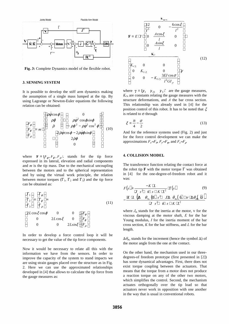
The complete dynamics model is obtained byassembling the previous submodels. Fig. 3 shows ablock diagram of the dynamics of our flexible arm,where the coupling among the previous submodelscan be observed. Friction in the flexible mechanismhas been neglected because friction in the passivejoints is very small and the viscous friction betweenair and the
We have experimentally proven that this model veryaccurately reproduces the dynamic behavior of ourprototype [9].mechanism can be considered null.
( )( )
( ) ( )( ) ( )
=
ξξξξ
ξξ
3323
2322
11
0
0
00
NN
NN
N
( ) ( )P
NL
L
ξξω =2
( )
( )( ) ( )
( ) ( )
44444 844444 76
&&&&
&&
4444 84444 76
&
&&48476
&&&&
&&
RQDFFHOHUDWL&RULROLV
RQDFFHOHUDWLO&HQWULSHWD
RQDFFHOHUDWL0RWLRQ
VLQ
VLQ
D
D
D
−+
−−+
=
=
ϕφϕρφϕρϕρ
φϕϕρφϕρϕρ
φϕρϕρρ
φ
ϕ
ρ
2cos2
2
0
0
cos
cos
cos
2
222
D
( ) )- ⋅=
ΓΓΓ
= ϕξ ,
3
2
17
( ) ( )( )7J VLQJP ϕϕcos0⋅⋅−=)
( ) )&3 ⋅=∆ ξ
( ) 3) ∆⋅= ξ
ralph
3855
( ) ( )
( ) ( ) ( )( )22
2
22
000
/.VV-
-V-/.
V/.VV-
/.V)
PFPFPF
⋅+⋅+⋅∆⋅+∆⋅+⋅∆⋅⋅⋅
−
Γ⋅⋅+⋅+⋅
⋅−=
νθνθθ
ν&
−+
−−+
⋅=
0
2
2cos2
cos
cos
0cos
222
2
ϕρϕϕφρϕφρ
ϕφρϕρϕϕφρ
ρϕρ
ϕφρ
ρ
ϕ
φ
&
&&&&
&&
&
&&
&&
&&
VLQ
VLQ
P
)
)
)
γσ
ξ
ξ
ξ
⋅
−
⋅
−
⋅⋅=
444444 8444444 76
4444 84444 76
*
PHDV
S
*
*
*
*,O
(,.
.
.
O$VLQO
$OO
,(
.
.
)
23
2
1
23
cos300
00
00
00
0cos
0
cos60
12
≈
ΓΓΓ
=
ΓΓΓ
ρ
ϕ
φ
ρ
ϕ
φ
ξξ
ϕξ
)
)
)
/VLQ
/
/
200
0cos20
00coscos2
3
2
1
24
σπξ −=
91
−1
1−1
.a
.Ö ⋅
CoulΓ
)LJ���� Complete Dynamics model of the flexible robot.
���6(16,1*�6<67(0
It is possible to develop the stiff arm dynamics makingthe assumption of a single mass lumped at the tip. Byusing Lagrange or Newton-Euler equations the followingrelation can be obtained:
(10)
where ( )ρϕφ ))) ,,=) stands for the tip forceexpressed in its lateral, elevation and radial componentsand P is the tip mass. Due to the mechanical uncouplingbetween the motors and to the spherical representationand by using the virtual work principle, the relationbetween motor torques (G1, G2 and G3) and the tip forcecan be obtained as:
(11)
In order to develop a force control loop it will benecessary to get the value of the tip force components.
Now it would be necessary to relate all this with theinformation we have from the sensors. In order toimprove the capacity of the system to stand impacts weare using strain gauges placed over the structure as in Fig.2. Here we can use the approximated relationshipsdeveloped in [4] that allows to calculate the tip force fromthe gauge measures as:
(12)
where ( )W
3211 γγγ= are the gauge measures,.*L are constants relating the gauge measures with thestructure deformations, and $ the bar cross section.This relationship was already used in [4] for theposition control of this robot. It has to be noted that xis related to s through
(13)
And for the reference systems used (Fig. 2) and justfor the force control development we can make theapproximations )[ )f, )\ )j, and )] )r�
���&2//,6,21�02'(/
The transference function relating the contact force atthe robot tip ) with the motor torque G was obtainedin [4] for the one-degree-of-freedom robot and itwas:
(9)
where -P stands for the inertia at the motor, n for theviscous damping at the motor shaft, ( for the barYoung modulus, , for the inertia moment of the barcross section, . for the bar stiffness, and / for the barlength.
DqPF stands for the increment (hence the symbol D) ofthe motor angle from the one at the contact.
On the other hand, the mechanism used in our three-degrees-of freedom prototype (first presented in [2])has some dynamical advantages. First, there does notexist torque coupling between the actuators. Thatmeans that the torque from a motor does not producea reaction torque on any of the other two motors,which simplifies the control. Second, the mechanismactuates orthogonally over the tip load so thatactuators never work in opposition with one anotherin the way that is usual in conventional robots.
ralph
3856
5 ⋅+=PW
>−WW
ˆ
ζ>W
&
ε>−WW
&̂&
This way we can assume that the whole robot structurehas the equivalent transfer function (9) for every givenposition an for each motor at a time. Now . stands for theequivalent stiffness of the whole structure and / becomesequivalent to the radial coordinate of the tip. This meansthat we have different transfer functions for each motorand for each specific robot configuration which wouldmake infinite of them. However we will show in furthercommunications that it is possible to develop a set ofrobust robot controllers for the contact whoseperformance would be acceptable for a good range ofpositions.
���&2//,6,21�'(7(&7,21
A method was developed in [4] for the free movementcontrol of the three-degree-of-freedom flexible arm. Thiscontrol was based on the information generated by straingauges placed at the robot structure. Now it is necessaryto develop a collision detection mechanism reliableenough to be able to switch between this controller andanother one to be developed for the control of the robotwhen in contact with the environment. A previousanalysis was carried out in [3] for the one-degree-of-freedom flexible arm, also based on the informationprovided from strain gauges. Here we are going to extentthat method for its use in the new three-degrees-of-freedom arm.
We take as W the set of motor angles that the robot
would need to get the desired tip position provided that itsstructure was rigid. This way it is possible (as was done in[3]) to calculate this angular tip position of the arm
W
from the gauges and encoders signals as:
(14)
where 5 stands for the matrix that relates the tipdisplacement due to the structural deformation expressedas gauge measures with the motor angles needed tocompensate them. This matrix can be easily obtainedfrom the relations introduced in [4] for their use in the tipposition control; which can be the one used in [9], onceadapted to the gauges signals as in [4].
Therefore it can be deduced the existence of collisionwhen:
1) The angular position of the arm tip differs from itsreference more than a given threshold value l.
(15)
This condition was already analyzed in [3] for the one-degree-of-freedom flexible arm and it was found that therequired signals were highly affected by noise so that thefiltering process was critic.
2) The tip velocity modulus approaches zero more that agiven threshold value z.
(16)
3) The tip angular velocity W differs from its
reference W more than a given threshold value e.
(17)
The angular velocity can be obtained as the timederivative of
W. This means that
W can be very
affected by noise notwithstanding the previousfiltering of the gauges signals. However, anappropriate combination of the three previousconditions and their thresholds l��z and e lead to avery accurate detection.
As W is being calculated it is possible to determine
the exact position of the impact surface, and withfurther calculations it will be also possible todetermine its direction. We will find this useful in thefuture development of the position/force controller,even more so when it has to contemplates thepossibility of sliding.
���6,08/$7('�(;3(5,0(17
This collision detection method has to be usedtogether with a force controller which is underdevelopment and that will be the object of furthercommunications. This way it would be possible toshift from the position controller to the forcecontroller by using the collision detection mechanismpresented above.
The collision detection mechanism has beenimplemented in the prototype but safe experimentscan not be carried out without first discussing theforce controller.
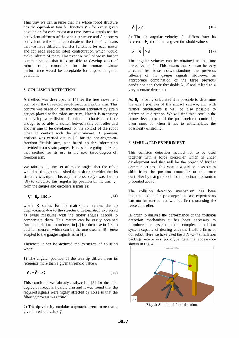
In order to analyze the performance of the collisiondetection mechanism it has been necessary tointroduce our system into a complex simulationsystem capable of dealing with the flexible links ofour robot. Here we have used the $GDPV¹ simulationpackage where our prototype gets the appearanceshown in Fig. 4.
)LJ���� Simulated flexible robot.
front model=robflex
x
y
z
ralph
3857
For the experiment the first motor of the robot (q1) rotate0.2UDG in 1VHF, making the robot collide with a surfacewhen the tip angle reaches 0.15UDG while the two otherangles remain q2=0 and q3=p/2.
The robot stiffness for this position is considered to be.=275. In order to allow the convergence of thesimulation the system switches to a rough force controllerwhen the collision is detected. The controller used is asimple PID controller with a zero in –2.8, a pole in –10,and gain of .5=1, this controller is used for a referenceforce of 101Z.
The threshold values used for the experiment arel=0.004P, z=�0.1P�VHF��For this specific experiment thevalue of e is not relevant.
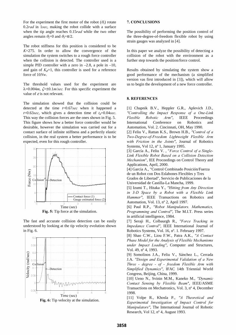
The simulation showed that the collision could bedetected at the time W=0.67VHF when it happened aW=0.63VHF, which gives a detection time of WG=0.04VHF.This way the collision forces are the ones shown in Fig. 5.This figure shows how a better force controller would bedesirable, however the simulation was carried out for acontact surface of infinite stiffness and a perfectly elasticcollision, in the real system a better performance is to beexpected, even for this rough controller.
)LJ���� Tip force at the simulation.
The fast and accurate collision detection can be easilyunderstood by looking at the tip velocity evolution shownin Fig. 6.
)LJ���� Tip velocity at the simulation.
���&21&/86,216
The possibility of performing the position control ofthe three-degree-of-freedom flexible robot by usingstrain gauges was analyzed in [4].
In this paper we analyze the possibility of detecting acollision of the robot with the environment as afurther step towards the position/force control.
Results obtained by simulating the system show agood performance of the mechanism (a simplifiedversion vas first introduced in [3]), which will allowus to begin the development of a new force controller.
���5()(5(1&(6
[1] Chapnik B.V., Heppler G.R., Aplevich J.D.,&RQWUROOLQJ� WKH� ,PSDFW� 5HVSRQVH� RI� D� 2QH�/LQN)OH[LEOH� 5RERWLF� $UP, IEEE ProceedingsInternational Conference on Robotics andAutomation, Vol. 2. Cincinnati, OH, May 1990.[2] Feliu V., Rattan K.S., Brown H.B., &RQWURO�RI�D7ZR�'HJUHH�RI�)UHHGRP� /LJKWZHLJKW� )OH[LEOH� $UPZLWK� )ULFWLRQ� LQ� WKH� -RLQWV, Journal of RoboticsSystems, Vol 12, nº 1, January 1995.[3] García A., Feliu V. , ")RUFH�&RQWURO�RI�D�6LQJOH�/LQN� )OH[LEOH� 5RERW� %DVHG� RQ� D� &ROOLVLRQ�'HWHFWLRQ0HFKDQLVP", IEE Proceedings on Control Theory andApplications, April, 2000.[4] García A., "Control Combinado Posición/Fuerzade un Robot con Dos Eslabones Flexibles y TresGrados de Libertad", Servicio de Publicaciones de laUniversidad de Castilla-La Mancha, 1999.[5] Izumi T., Hitaka Y., +LWWLQJ�IURP�$Q\�'LUHFWLRQLQ� ��'� 6SDFH� E\� D� 5RERW� ZLWK� D� )OH[LEOH� /LQN+DPPHU, IEEE Transactions on Robotics andAutomation, Vol. 13, nº 2, April 1997.[6] Paul R.P., 5RERW� 0DQLSXODWRUV�� 0DWKHPDWLFV�3URJUDPPLQJ� DQG�&RQWURO, The M.I.T. Press seriesin artificial intelligence, 1984.[7] Seraji H., Colbaurgh R., )RUFH� 7UDFNLQJ� LQ,PSHGDQFH� &RQWURO, IEEE International Journal ofRobotics Systems, Vol. 16, nº. 1. February 1997.[8] Shao C.W., Liou F.W., Patra A.K., $� &RQWDFW3KDVH�0RGHO�IRU�WKH�$QDO\VLV�RI�)OH[LEOH�0HFKDQLVPVXQGHU� ,PSDFW� /RDGLQJ, Computer and Structures,Vol. 49, nº 4, 1993.[9] Somolinos J.A., Feliu V., Sánchez L., CerradaJ.A. 'HVLJQ� DQG�([SHULPHQWDO�9DOLGDWLRQ� RI� D�1HZ7KUHH� �� GHJUHH� �� RI� �� IUHHGRP� )OH[LEOH� $UP� ZLWK6LPSOLILHG� '\QDPLFV, IFAC 14th Triennial WorldCongress, Beijing, China, 1999.[10] Ueno N., Svinin M.M., Kaneko M., '\QDPLF&RQWDFW� 6HQVLQJ� E\� )OH[LEOH� %HDP', IEEE/ASMETransactions on Mechatronics, Vol. 3, nº 4, December1998.[11] Volpe R., Khosla P., $� 7KHRUHWLFDO� DQG([SHULPHQWDO� ,QYHVWLJDWLRQ� RI� ,PSDFW� &RQWURO� IRU0DQLSXODWRUV, The International Journal of RoboticResearch, Vol 12, nº 4, August 1993.
ralph
3858