Zone-plate-array lithography (ZPAL): optical maskless lithography for cost-effective patterning
Upload
independentCategory
view
1download
0
Nano-Confinement Induced ChainAlignment in Ordered P3HTNanostructures Defined by NanoimprintLithographyMukti Aryal, Krutarth Trivedi, and Wenchuang (Walter) Hu*
Department of Electrical Engineering, The University of Texas at Dallas, Richardson, Texas
During the past decade, conjugatedpolymers have emerged as cost-effective functional materials for
organic electronic devices such as solar
cells1,2 and field effect transistors (FETs).3,4
In organic devices, polymer morphology
(size and shape of polymer nanostructures
or phases) and chain orientation or crystal-
linity have been shown to have strong ef-
fects on charge-carrier mobility and overall
device performance.5,6 This is because
charge transport in conjugated polymer is
anisotropic, resulting from electrons delo-
calized along the polymer backbone and
the overlap of �-orbitals.7 For example,
charge mobility of poly(3-hexylthiophene)
(P3HT) along the ��� stacking and back-
bone direction can be higher than 0.1 cm2/
V · s, while being several orders of magni-
tude lower along the insulating side
chains.8,9 Consequently, charge transport,
mobility, and even optical properties across
the active layer of a device can be signifi-
cantly affected by ordering and crystallinity
of P3HT.8�11 In addition to chain orientation,
control over polymer morphology can be
important for device performance as well.
For example, in bulk heterojunction (BHJ)
solar cell structures, control of nanomor-
phology of the heterojunction plays a criti-
cal role in exciton dissociation and charge
transport.5 In most cases, chain alignment
and morphology are interrelated and it is
difficult to control both factors simulta-
neously and favorably. In BHJ solar cells,
the hole mobility is just on the order of 10�4
cm2/V · s, which is attributed to both ran-
dom chain alignment and overlapping
phase morphology.5,10,12
Several techniques have been reported
to promote nanoscale phase separation,
polymer crystallization, and chain align-ment in bulk heterojunction solar cells andFETs. Studies suggest polymer chain align-ment and crystallization can be controlledto some extent by spincoating techniques,13
solution concentration, and composition,drying process,5,14 and surfacemodification.9,15,16 Processing techniquessuch as nanorubbing,17,18 electrospinning,19
and nanoimprint lithography20�23 havebeen attempted to control polymer mor-phology and improve crystallinity/orienta-tion of P3HT. These techniques haveachieved some degree of chain ordering,some of them leading to improved deviceperformance. However, a comprehensiveunderstanding of chain alignment in de-fined nanostructure morphologies remainsunknown. Simultaneous control of polymerchain alignment and morphology is still achallenge.
Previously, we have demonstrated theuse of nanoimprint lithography to definehigh-density nanopillars/pores in P3HT
*Address correspondence [email protected].
Received for review July 20, 2009and accepted August 26, 2009.
Published online September 4, 2009.10.1021/nn900831m CCC: $40.75
© 2009 American Chemical Society
ABSTRACT Control of polymer morphology and chain orientation is of great importance in organic solar cells
and field effect transistors (OFETs). Here we report the use of nanoimprint lithography to fabricate large-area,
high-density, and ordered nanostructures in conjugated polymer poly(3-hexylthiophene) or P3HT, and also to
simultaneously control 3D chain alignment within these P3HT nanostructures. Out-of-plane and in-plane grazing
incident X-ray diffraction were used to determine the chain orientation in the imprinted P3HT nanostructures,
which shows a strong dependence on their geometry (gratings or pillars). Vertical chain alignment was observed
in both nanogratings and nanopillars, indicating strong potential to improve charge transport and optical
properties for solar cells in comparison to bulk heterojunction structure. For P3HT nanogratings, ��� stacking
along the grating direction with an angular distribution of �20° was found, which is favorable for OFETs. We
propose the chain alignment is induced by the nanoconfinement during nanoimprinting via ��� interaction
and hydrophobic interaction between polymer chain and mold surfaces.
KEYWORDS: polymer chain alignment · nanostructures · poly(3-hexylthiophene) orP3HT · organic solar cells · organic field effect transistors
ARTIC
LE
www.acsnano.org VOL. 3 ▪ NO. 10 ▪ 3085–3090 ▪ 2009 3085
and form vertically interdigitized bicontinuous hetero-junction morphology for P3HT-fullerene derivative so-lar cells.20 In this study, a similar process is used to makelarge-area P3HT nanostructures with different geom-etry, for example, gratings and pillars. We then showthat the nanoimprinting process induces favorablechain alignment in all three-dimensions in these P3HTnanostructures, which is determined primarily by thegeometry of nanoconfinement during nanoimprint andthe surface properties of the mold. Interestingly, such3D chain configuration is desirable for both solar celland FET applications.
RESULTS AND DISCUSSIONIn our experiments, regioregular or RR P3HT was
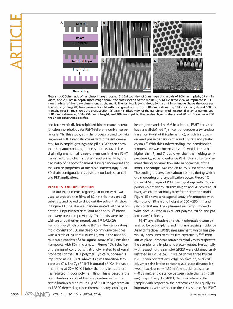
used to prepare thin films of 80 nm thickness on a Sisubstrate and baked to drive out the solvent. As shownin Figure 1A, the film was nanoimprinted with Si nano-grating (unpublished data) and nanoporous20 moldsthat were prepared previously. The molds were treatedwith an antiadhesion monolayer, 1H,1H,2H,2H-perfluorodecyltrichlorosilane (FDTS). The nanogratingmold consists of 200 nm deep, 65 nm wide trencheswith a pitch of 200 nm (Figure 1B) while the nanopo-rous mold consists of a hexagonal array of 350 nm deepnanopores with 80 nm diameter (Figure 1D). Selectionof the imprint conditions is strongly related to physicalproperties of the P3HT polymer. Typically, polymer isimprinted at 20�50 °C above its glass transition tem-perature (Tg). The Tg of P3HT is around 67 °C.24 Howeverimprinting at 20�50 °C higher than this temperaturehas resulted in poor polymer filling. This is because thecrystallization occurs at this temperature range. Thecrystallization temperature (Tc) of P3HT ranges from 80to 128 °C depending upon thermal history, cooling or
heating rate and time.25,26 In addition, P3HT does nothave a well-defined Tg since it undergoes a twist-glasstransition (twist of thiophene ring), which is a quasi-ordered phase transition of liquid crystals and plasticcrystals.24 With this understanding, the nanoimprinttemperature was chosen at 170 °C, which is muchhigher than Tg and Tc but lower than the melting tem-perature Tm, so as to enhance P3HT chain disentangle-ment during polymer flow into nanocavities of themold. The sample was cooled to 25 °C for demolding.The cooling process takes about 30 min, during whichchain ordering and crystallization occur. Figure 1Cshows SEM images of P3HT nanogratings with 200 nmperiod, 65 nm width, 200 nm height, and 20 nm residuallayer, which are faithfully transferred from the mold.Figure 1E shows a hexagonal array of nanopores withdiameter of 80 nm and height of 200�250 nm, andpitch of 100 nm. The optimized nanoimprint condi-tions have resulted in excellent polymer filling and pat-tern transfer fidelity.
P3HT crystallization and chain orientation were ex-amined by out-of-plane and in-plane grazing incidenceX-ray diffraction (GIXRD) measurement, which has pre-viously been used to study film crystallinity.15,16 Bothout-of-plane (detector rotates vertically with respect tothe sample) and in-plane (detector rotates horizontallywith respect to the sample) GIXRD were obtained, as il-lustrated in Figure 2A. Figure 2A shows three typicalP3HT chain orientations, edge-on, face-on, and verti-cal, where the lattice constants a, b, c are distance be-tween backbones (�1.69 nm), �-stacking distance(�0.38 nm), and distance between side chains (�0.38nm), respectively. In GIXRD, the orientation of thesample, with respect to the detector can be equally asimportant as with respect to the X-ray source. For P3HT
Figure 1. (A) Schematic of nanoimprinting process. (B) SEM top view of Si nanograting molds of 200 nm in pitch, 65 nm inwidth, and 200 nm in depth. Inset image shows the cross section of the mold; (C) SEM 45° tilted view of imprinted P3HTnanogratings of the same dimensions as the mold. The residual layer is about 20 nm and inset image shows the cross sec-tion of the grating. (D) Nanoporous Si mold with hexagonal pore array of 80 nm in diameter, 350 nm in height, and 100 nmin pitch. Inset image shows the cross section. (E) SEM 45° tilted view of the nanoimprinted hexagonal array of nanopillarsof 80 nm in diameter, 200�250 nm in height, and 100 nm in pitch. The residual layer is also about 20 nm. Scale bar is 200nm unless otherwise specified.
ART
ICLE
VOL. 3 ▪ NO. 10 ▪ ARYAL ET AL. www.acsnano.org3086

nanograting samples, in-plane GIXRD measurements
were taken with grating direction along or parallel to
the direction of incident X-rays (y-axis in Figure 2A, re-
ferred to as Grating�) and with grating direction perpen-
dicular to the direction of incident X-rays (x-axis in Fig-
ure 2A, referred to as Grating �).
The out-of-plane GIXRD results of thin film, nano-
grating, and nanopillar samples are shown in Figure
2C. Large intensity (100) peaks at 5.2°, corresponding
to lattice parameter a, were observed for all samples,
suggesting dominance of edge-on chain orientation. In
addition, the (010) peak at 23.4°, corresponding to the
lattice parameter b, was not detected, indicating
face-on chain orientation is not present (or negligible)
in all samples. Comparatively, the (100) peak intensity
for nanopillars and nanogratings was significantly re-
duced compared to thin film with similar volume, show-
ing that edge-on dominance in the nanoimprinted
P3HT is much reduced compared to unpatterned P3HT
(thin film). This could be attributed to reordering of
P3HT chains in the nanopillars and nanogratings dur-
ing the nanoimprint process. We believe that the finite,
lower intensity of this peak for patterned P3HT is result-
ant primarily from the residue layer of the nanoim-
printed structures. This observation seems to be in
agreement with a study by Cui et al.22 The out-of-plane
GIXRD results alone cannot provide a complete under-
standing of chain orientation of P3HT inside nanoim-
printed structures. To gain a better understanding, in-
plane XRD measurement was performed both along
and perpendicular to the grating direction and results
are shown in Figure 2D. The (100) peak was strongest
for Grating �, while the same peak was weakest for Grat-
ing �, indicating strong anisotropic chain orientation
in nanoimprinted gratings. The strong (100) peak for
Grating �, corresponding to lattice constant a, indicates
that the only possible chain configurations in nanograt-
ings are either face-on or vertical. However, the out-of-
plane GIXRD measurement (Figure 2C) showed no
face-on chain orientation (010 peak) in all samples.
Therefore, this proves that chain orientation inside
nanoimprinted gratings is, indeed, vertical. Further-
more, when the same nanograting samples were ro-
tated by 90° for Grating �, the (100) peak disappeared
and (010) peak intensity increased, showing that for ver-
tical chain orientation, the �-stacking is not randomly
distributed in the x�y plane, but rather anisotropically
aligned in one direction, that is, along the grating. With
the combination of out-of-plane and in-plane GIXRD re-
sults, a complete picture of 3D P3HT chain configura-
Figure 2. (A) Schematic of GIXRD setup for out-of-plane and in-plane measurements. (B) Schematic of edge-on, face-on,and vertical orientation of P3HT chains on surface. Out-of-plane and in-plane measurement are used to detect the lattice con-stants along z- axis and x-axis, respectively. (C) Out-of-plane GIXRD measurement graphs for the nanogratings, nanopillars,and unpatterned thin film samples. (D) In-plane GIXRD measurement graphs for all samples, where Grating � and Grating �referred as measurements made with grating direction parallel and perpendicular to the direction of incident X-rays, respec-tively. The side figures show magnified views of the (100) peaks (top) and (010) peaks (bottom).
ARTIC
LE
www.acsnano.org VOL. 3 ▪ NO. 10 ▪ 3085–3090 ▪ 2009 3087

tion for nanogratings is obtained, that is, vertical back-
bone alignment with �-stacking along the grating
direction as shown in Figure 3B (ideal case).
As for the nanopillar morphology, the (100) peak in-
tensity in in-plane GIXRD (Figure 2D) was much lower
than Grating � but stronger than the unpatterned film
as well as Grating �, as shown in top magnified figure
of Figure 2D. Similarly, the (010) peak for nanopillars is
equally intense but broader compared to Grating � and
unpatterned film (bottom magnified figure of Figure
2D). These observations indicate the presence of verti-
cally oriented P3HT chains in the nanopillars. The mea-
sured signal for pillars did not change when thesamples were rotated during measurements, in-dicating random or isotropic chain configurationin the x�y plane. Figure 3C depicts the chainconfiguration in nanopillars (ideal case). Com-pared to nanograting and nanopillar samples,unpatterned P3HT film mostly exhibits edge-onchain orientation (Figure 2B) with random chainconfiguration in the x�y plane, as evidenced byno peaks for the film in Figure 2D.
The above-mentioned results and analysishave shown that reordering of polymer chains isstrongly affected by the geometry (gratings orpillars) of the mold, which confines and guidesthe flow of polymer to form P3HT nanostructures.While in-plane measurements (Grating � andGrating �) clearly prove that chains inside nano-gratings are preferentially aligned in a certain di-rection, the two measurements do not revealthe variation in direction of chain alignment, withrespect to grating direction. To measure the dis-tribution of chain alignment directions, an azi-muthal (�) in-plane-prefer-orientation scan withthe detector fixed at a 2� angle of 5.2°, corre-sponding to (100) peak, was performed. Asshown in Figure 4A, the sample was rotatedfrom �40° to 115° in increments of 0.04° to scana slew of directions, including the Grating � andGrating � cases, for the (100) peak. Figure 4Bshows the (100) peak intensity with respect to
nanograting sample rotation (only �30° to 30° isshown). As expected, a peak maximum was observedwhen the incident beam is almost parallel to the nan-ograting direction (an angle of �3°, likely due to align-ment error), which agrees with Grating � data in Figure2D. As seen in Figure 4B, the distribution has a width of�20°, indicating the chain alignment (� stacking) hasa finite variation along the grating direction. We believethat this variation can be minimized with optimizednanoimprint conditions (e.g., longer imprinting time),appropriate structural aspect ratio, and better qualitypolymer.
Figure 3. (A) Mechanism of P3HT chain alignment due to polymer flow and inter-action between P3HT side chain and FDTS treated surface of the mold cavity dur-ing nanoimprinting; schematic of ideal structures of P3HT chain alignment in (B)nanograting and (C) nanopillars.
Figure 4. (A) Schematic of GIXRD setup for orientation measurement of nanograting sample. The detector is fixed at 2� �5.2° and the angle between X-ray incident beam and line grating varies when the thin film stage rotates though an angle �.(B) Diffraction intensity vs � for the detector fixed at 2� � 5.2°.
ART
ICLE
VOL. 3 ▪ NO. 10 ▪ ARYAL ET AL. www.acsnano.org3088
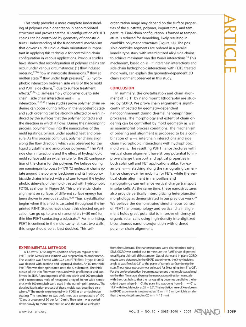
This study provides a more complete understand-ing of polymer chain orientation in nanoimprintedstructures and proves that the 3D configuration of P3HTchains can be controlled by geometry of nanostruc-tures. Understanding of the fundamental mechanismthat governs such unique chain orientation is impor-tant in applying this technique for controlling chainconfiguration in various applications. Previous studieshave shown that reconfiguration of polymer chains canoccur under various circumstances: (1) flow inducedordering,27,28 flow in nanoscale dimensions,29 flow atmolten state,30 flow under high pressure;31 (2) hydro-phobic interaction between side walls of the Si moldand P3HT side chains,32 due to surface treatmenteffects;15,16 (3) self-assembly of polymer due to sidechain�side chain interaction and ���
interaction.15,16,33 These studies prove polymer chain or-dering can occur during reflow in the viscoelastic stateand such ordering can be strongly affected or even in-duced by the surfaces that the polymer contacts andthe direction in which it flows. During the nanoimprintprocess, polymer flows into the nanocavities of themold (gratings, pillars), under applied heat and pres-sure. As this process continues, polymer chains alignalong the flow direction, which was observed for theliquid crystalline and amorphous polymers.34 The P3HTside chain interactions and the effect of hydrophobicmold surface add an extra feature for the 3D configura-tion of the chains for this polymer. We believe duringour nanoimprint process (�170 °C) molecular chains ro-tate around the polymer backbone and its hydropho-bic side chains interact with and turn toward the hydro-phobic sidewalls of the mold (treated with hydrophobicFDTS), as shown in Figure 3A. This preferential chainalignment on surfaces of different surface energy hasbeen shown in previous studies.15,16 Thus, crystallizationbegins when this effect is cascaded throughout the im-printed P3HT. Studies have shown this directed organi-zation can go up to tens of nanometers (�50 nm) forthin film P3HT contacting a substrate.15 For imprinting,P3HT is confined in the mold cavity (at least two walls),this range should be at least doubled. This self-
organization range may depend on the surface proper-ties of the substrate, polymer, imprint time, and tem-perature. Final chain configuration is formed as temper-ature is reduced for demolding, likely resulting incomblike polymeric structures (Figure 3A). The pos-sible comblike segments are ordered in a parallellamella-type stack with interdigitized alkyl side chainsto achieve maximum van der Waals interactions.33 Thismechanism, based on ��� interchain interactions andside chain hydrophobic interactions with FDTS treatedmold walls, can explain the geometry-dependent 3Dchain alignment observed in this study.
CONCLUSIONIn summary, the crystallization and chain align-
ment of P3HT by nanoimprint lithography are stud-ied by GIXRD. We prove chain alignment is signifi-cantly impacted by geometry-dependentnanoconfinement during thermal nanoimprintingprocesses. The morphology and extent of chain or-dering can be controlled by mold geometry as wellas nanoimprint process conditions. The mechanismof ordering and alignment is proposed to be a com-bination of ��� interchain interactions and sidechain hydrophobic interactions with hydrophobicmold walls. The resulting P3HT nanostructures withvertical chain alignment have strong potential to im-prove charge transport and optical properties inboth solar cell and FET applications alike. For ex-ample, ��� stacking along the nanograting can en-hance charge-carrier mobility for FETs, while the ver-tical chain alignment in nanopillars andnanogratings can enhance vertical charge transportin solar cells. At the same time, these nanostructuresalso provide vertically interdigitizing heterojunctionmorphology as demonstrated in our previous work.20
We believe the demonstrated simultaneous controlof P3HT nanomorphology and vertical chain align-ment holds great potential to improve efficiency oforganic solar cells using high-density interdigitizedbicontinuous nanoheterojunction with orderedpolymer chain alignment.
EXPERIMENTAL METHODSA 1.5 wt % (17.55 mg/mL) portion of region-regular or RR-
P3HT (Reike Metals Inc.) solution was prepared in chlorobenzene.The solution was filtered with 0.22 �m PTFE filter. P-type (100) Siwas cleaned with acetone and isopropyl alcohol. An 80 nm thickP3HT film was then spincoated onto the Si substrates. The thick-nesses of the thin film were measured with profilometer and con-firmed in SEM. A grating mold of 65 nm width and 200 nm pitchand a nanoporous mold of hexagonal array of 80 nm wide nanop-ores with 100 nm pitch were used in the nanoimprint process. Thedetailed fabrication process of these molds was described else-where.20 The molds were treated with FDTS as an antiadhesioncoating. The nanoimprint was performed at a temperature of 170°C and a pressure of 50 bar for 10 min. The system was cooled
down slowly to room temperature, and the mold was released
from the substrate. The nanostructures were characterized usingSEM. GIXRD was carried out to measure the P3HT chain alignmenton a Rigaku Ultima III diffractometer. Out-of-plane and in-plane GIXRDresults were obtained. In the GIXRD experiments, the X-ray incidentangle � was fixed at 0.5° to the plane of sample surface during thescan. The angular spectrum was collected for 2� ranging from 3° to 25°.For the prefer orientation � scan measurement, the sample was placedon the thin film stage aligning the nanograting direction manuallywith the cross hair so that the nanograting becomes parallel to the in-cident beam when � 0°, the scanning was done from � �40° to115° with fixed detector at 2� 5.2°. The irradiation area of X-ray beamin GIXRD experiments is estimated as 15 mm 5 mm, which is smallerthan the imprinted samples (20 mm 15 mm).
ARTIC
LE
www.acsnano.org VOL. 3 ▪ NO. 10 ▪ 3085–3090 ▪ 2009 3089

Acknowledgment. This work is supported by the National Sci-ence Foundation (No. ECCS-0901759) and the Air Force Officeof Scientific Research (No. FA9550-06-1-0403).
REFERENCES AND NOTES1. Gebeyehu, D.; Brabec, C. J.; Padinger, F.; Fromherz, T.;
Hummelen, J. C.; Badt, D.; Schindler, H.; Sariciftci, N. S. TheInterplay of Efficiency and Morphology in PhotovoltaicDevices Based on Interpenetrating Networks ofConjugated Polymers with Fullerenes. Synth. Met. 2001,118, 1–9.
2. Hoppe, H.; Sariciftci, N. S. Organic Solar Cells: An Overview.J. Mater. Res. 2004, 19, 1924–1945.
3. Friend, R. H.; Gymer, R. W.; Holmes, A. B.; Burroughes, J. H.;Marks, R. N.; Taliani, C.; Bradley, D. D. C.; Dos Santos, D. A.;Bredas, J. L.; Logdlund, M.; et al. Electroluminescence inConjugated Polymers. Nature 1999, 397, 121–128.
4. Ong, B. S.; Wu, Y. L.; Liu, P.; Gardner, S. High-PerformanceSemiconducting Polythiophenes for Organic Thin-FilmTransistors. J. Am. Chem. Soc. 2004, 126, 3378–3379.
5. Benanti, T. L.; Venkataraman, D. Organic Solar Cells: AnOverview Focusing on Active Layer Morphology.Photosynth. Res. 2006, 87, 73–81.
6. Briseno, A. L.; Mannsfeld, S. C. B.; Jenekhe, S. A.; Bao, Z.;Xia, Y. Introducing Organic Nanowire Transistors. Mater.Today 2008, 11, 38–47.
7. Gustafsson, G.; Inganas, O.; Stafstrom, S. OpticalAnisotropy of Neutral and Doped Poly(3-Octylthiophene).Solid State Commun. 1990, 76, 203–208.
8. Sirringhaus, H.; Brown, P. J.; Friend, R. H.; Nielsen, M. M.;Bechgaard, K.; Langeveld-Voss, B. M. W.; Spiering, A. J. H.;Janssen, R. A. J.; Meijer, E. W.; Herwig, P.; et al. Two-Dimensional Charge Transport in Self-Organized, High-Mobility Conjugated Polymers. Nature 1999, 401, 685–688.
9. Sirringhaus, H.; Wilson, R. J.; Friend, R. H.; Inbasekaran, M.;Wu, W.; Woo, E. P.; Grell, M.; Bradley, D. D. C. MobilityEnhancement in Conjugated Polymer Field-EffectTransistors through Chain Alignment in a Liquid-Crystalline Phase. Appl. Phys. Lett. 2000, 77, 406–408.
10. Comoretto, D.; Dellepiane, G.; Marabelli, F.; Cornil, J.; dosSantos, D. A.; Bredas, J. L.; Moses, D. Optical Constants ofHighly Stretch-Oriented Poly(P-phenylene-vinylene): AJoint Experimental and Theoretical Study. Phys. Rev. B2000, 62, 10173–10184.
11. Svensson, M.; Zhang, F.; Inganas, O.; Andersson, M. R.Synthesis and Properties of Alternating PolyfluoreneCopolymers with Redshifted Absorption for Use in SolarCells. Synth. Met. 2003, 135, 137–138.
12. Bassett, D. C., Principles of Polymer Morphology, Illustrateded.; Cambridge University Press: New York, 1981; pp 146�166.
13. DeLongchamp, D. M.; Vogel, B. M.; Jung, Y.; Gurau, M. C.;Richter, C. A.; Kirillov, O. A.; Obrzut, J.; Fischer, D. A.;Sambasivan, S.; Richter, L. J.; et al. Variations inSemiconducting Polymer Microstructure and HoleMobility with Spin-Coating Speed. Chem. Mater. 2005, 17,5610–5612.
14. Kim, D. H.; Jang, Y.; Park, Y. D.; Cho, K. Controlled One-Dimensional Nanostructures in Poly(3-hexylthiophene)Thin Film for High-Performance Organic Field-EffectTransistors. J. Phys. Chem. B 2006, 110, 15763–15768.
15. Kline, R. J.; McGehee, M. D.; Toney, M. F. Highly OrientedCrystals at the Buried Interface in Polythiophene Thin-FilmTransistors. Nat. Mater. 2006, 5, 222–228.
16. Chang, J. F.; Sun, B. Q.; Breiby, D. W.; Nielsen, M. M.; Solling,T. I.; Giles, M.; McCulloch, I.; Sirringhaus, H. EnhancedMobility Of Poly(3-hexylthiophene) Transistors by Spin-Coating from High-Boiling-Point Solvents. Chem. Mater.2004, 16, 4772–4776.
17. Heil, H.; Finnberg, T.; von Malm, N.; Schmechel, R.; vonSeggern, H. The Influence of Mechanical Rubbing on theField-Effect Mobility in Polyhexylthiophene. J. Appl. Phys.2003, 93, 1636–1641.
18. Nagamatsu, S.; Takashima, W.; Kaneto, K.; Yoshida, Y.;Tanigaki, N.; Yase, K. Backbone Arrangement in “Friction-Transferred” Regioregular Poly(3-alkylthiophene)S.Macromolecules 2003, 36, 5252–5257.
19. Li, D.; Xia, Y. N. Electrospinning of Nanofibers: Reinventingthe Wheel. Adv. Mater. 2004, 16, 1151–1170.
20. Aryal, M.; Buyukserin, F.; Mielczarek, K.; Zhao, X. M.; Gao,J. M.; Zakhidov, A.; Hu, W. C. Imprinted Large-Scale HighDensity Polymer Nanopillars for Organic Solar Cells. J. Vac.Sci. Technol., B 2008, 26, 2562–2566.
21. Cheyns, D.; Vasseur, K.; Rolin, C.; Genoe, J.; Poortmans, J.;Heremans, P. Nanoimprinted Semiconducting PolymerFilms with 50 nm Features and their Application toOrganic Heterojunction Solar Cells. Nanotechnology 2008,19, 424016–414021.
22. Cui, D.; Li, H.; Park, H.; Cheng, X. Improving Organic Thin-Film Transistor Performance by Nanoimprint-InducedChain Ordering. J. Vac. Sci. Technol., B 2008, 26, 2404–2409.
23. Kim, M. S.; Kim, J. S.; Cho, J. C.; Shtein, M.; Guo, L. J.; Kim, J.Flexible Conjugated Polymer Photovoltaic Cells withControlled Heterojunctions Fabricated Using NanoimprintLithography. Appl. Phys. Lett. 2007, 90, 123113–123115.
24. Yazawa, K.; Inoue, Y.; Yamamoto, T.; Asakawa, N. TwistGlass Transition in Regioregulated Poly(3-alkylthiophene).Phys. Rev. B 2006, 74, 094204–094215.
25. Yang, C.; Orfino, F. P.; Holdcroft, S. A PhenomenologicalModel for Predicting Thermochromism of Regioregularand Nonregioregular Poly(3-alkylthiophenes).Macromolecules 1996, 29, 6510–6517.
26. Zhao, Y.; Yuan, G. X.; Roche, P.; Leclerc, M. A CalorimetricStudy of the Phase-Transitions in Poly(3-hexylthiophene).Polymer 1995, 36, 2211–2214.
27. Beck, V. A.; Shaqfeh, E. S. G. Ergodicity-Breaking and theUnraveling Dynamics of a Polymer in Linear and NonlinearExtensional Flows. J. Rheol. 2007, 51, 561–574.
28. Checker, N.; Mackley, M. R.; Mead, D. W. On the Flow ofMolten Polymer into, within, and out of Ducts. Phil. Trans.R. Soc., A (London) 1983, 308, 451–477.
29. Rowland, H. D.; King, W. P.; Pethica, J. B.; Cross, G. L. W.Molecular Confinement Accelerates Deformation ofEntangled Polymers During Squeeze Flow. Science 2008,322, 720–724.
30. Lovinger, A. J.; Davis, D. D. Electron-MicroscopicInvestigation of the Morphology of a Melt-CrystallizedPolyaryletherketone. J. Appl. Phys. 1985, 58, 2843–2853.
31. Kanazawa, H.; Stejny, J.; Keller, A. Polymerization andStructure of Poly(sulfur nitride) Prepared under High-Pressure. J. Mater. Sci. 1991, 26, 1635–1639.
32. Yamamoto, K.; Ochiai, S.; Wang, X.; Uchida, Y.; Kojima, K.;Ohashi, A.; Mizutani, T. Evaluation of Molecular Orientationand Alignment of Poly(3-hexylthiophene) on Au (111) andon Poly(4-vinylphenol) Surfaces. Thin Solid Films 2008, 516,2695–2699.
33. Sandberg, H. G. O.; Frey, G. L.; Shkunov, M. N.; Sirringhaus,H.; Friend, R. H.; Nielsen, M. M.; Kumpf, C. UltrathinRegioregular Poly(3-hexyl thiophene) Field-EffectTransistors. Langmuir 2002, 18, 10176–10182.
34. Hu, Z. J.; Muls, B.; Gence, L.; Serban, D. A.; Hofkens, J.;Melinte, S.; Nysten, B.; Demoustier-Champagne, S.; Jonas,A. M. High-Throughput Fabrication of Organic NanowireDevices with Preferential Internal Alignment andImproved Performance. Nano Lett. 2007, 7, 3639–3644.
ART
ICLE
VOL. 3 ▪ NO. 10 ▪ ARYAL ET AL. www.acsnano.org3090
Copyright © 2022 FDOKUMEN