Simulations of and experiments on the holographic lithography fabrication of photonic crystals
Study of Barrier Coats for Application in Immersion 1 93 nmLithography
Francis Houlihan*, Wookyu Kim, Raj Sakamuri, Keino Hamilton, Alla Dimerli, David Abdallah,Andrew Romano, Ralph R. Dammel, Georg Pawlowski
AZ Electronic Materials, Somerville, NJAlex Raub, Steve BrueckUniversity ofNew Mexico
Keywords: 1 93 nm Immersion, barrier coat.ABSTRACT
We will describe our barrier coat approach for use in immersion 1 93 nm lithography. These banier coats may act aseither simple barriers providing protection against loss of resist components into water or in the case of one type of theseformulations which have a refractive index at 1 93 nm which is the geometric mean between that of the resist and waterprovide, also top antireflective properties. Either type of barrier coat can be applied with a simple spinning processcompatible with PGMEA based resin employing standard solvents such as alcohols and be removed during the usualresist development process with aqueous 0.26 N TMAH. We will discuss both imaging results with these materials onacrylate type 1 93 nm resists and also show some fundamental studies we have done to understand the function of thebarrier coat and the role of differing spinning solvents and resins. We will show LS (55 nm) and Contact Hole (80 nm)resolved with a 193 nm resist exposed with the interferometric tool at the University of New Mexico (213 nm) with andwithout the use of a barrier coat.
1. INTRODUCTIONRecent years have seen the rapid advance of 1 93 nm immersion lithography which has surplanted 157
nm on the semiconductor roadmap as the primary technique to reach the 65 nm node. This has occurredbecause immersion lithography is a technique that can be used to extend the depth of focus and resolutionlimits of 1 93 nm lithography imaging. In the traditional process of dry lithography imaging, air or some otherlow refractive index gas, lies between the lens and the wafer plane. This abrupt change in refractive indexcauses rays at the edge of the lens to undergo total internal reflection and not propagate to the wafer (Figure1). In immersion lithography a fluid is present between the objective lens and the wafer to enable higherorders of light to participate in image formation at the wafer plane. In this manner the effective numericalaperture of the optical lens (NA) can be increased to greater than 1 ,where NAwet n sinO, where NAwet S thenumerical aperture with immersion lithography, n1 is refractive index of liquid of immersion and sinO is theangular aperture of the lens. Increasing the refractive index of the medium between the lens and thephotoresist allows for greater resolution power and depth of focus. This in turn gives rise to greater processlatitudes in the manufacturing of IC devices1.
For 193 nm and 248 nm and higher wavelengths immersion lithography, water is of sufficientinherent transparency so that it can be used as the immersion fluid. Alternatively, if a higher NA is desired,water's refractive index can be increased by doping with UV transparent solutes. However, for 157 nmlithography, water's high absorbance makes it unsuitable as an immersion fluid. Currently certain oligomericfluorinated ether solvents have been used as suitable immersion fluids2.One important concern in immersion lithography is the extraction of components from the photoresist filminto the immersion fluid. These components may either be ones present in the film prior to exposure (e.g.base additives, photoacid generators, solvent, dissolution inhibitors, plasticizers, leveling agents,) or presentin the film during or shortly after exposures (e.g. photoacid, PAG photofragments, scission fragments from
*Az® Electronic Materials, Clariant Corporation, Somerville, NJ 08876, Frank.Houlihan(a AZ-EM.com, (908)429-3561
Advances in Resist Technology and Processing XXII, edited by John L. Sturtevant,Proceedings of SPIE Vol. 5753 (SPIE, Bellingham, WA, 2005)
0277-786X/05/$15 · doi: 10.1117/12.601768
78

the po'ymer or the other additives, salt ofthe photoacid and base additive.) The extraction ofthese materialsis of concern for two reasons: firstly, it may affect resist performance deleteriously, and the second is thedeposition of UV absorbing films on the objective lens in contact with the immersion fluid due to thephotoreaction of extracted components in the immersion fluid.
rg jflh
Figure 1 Difference in the optical path of light rays entering at the extreme edge of a lens for air and animmersion medium of higher refractive index. The rays show total internal reflection in air but propagate tothe wafer in the case of immersion lithography.
Thus there is a need for a barrier coat having good optical transparency at the exposure wavelength, whichcan be spun onto the photoresist from a solvent system which will not redissolve the photoresist, and wherethe barrier coating layer is also insoluble in the immersion liquid, but can be removed easily during thenormal aqueous base development step.
We have previously published an initial account of our work on immersion barrier coats3, this paperwill outline our recent progress in developing such materials.
2. EXPERIMENTAL2.1 Materials
The resist materials that we employed in this study consist of acrylate/methacrylate resins with pendantalicylic moieties similar in basic structures to polymers A-D in Scheme 1 used in early 193 nm immersion taskforce work under the auspices of the SEMATECH 193 urn these are typically formulated as typical spin casting solventsuch as PGMEA along with an amine base such as triethyl amine and a photoacid generator such as onium saltsgenerating photochemically super acids such as perfluorobutanesulfonic acid. The resist materials employed in thisstudy are AZ® 1 l2Op, AZ® EXP M3000, AZ® EXP IRC 1000, AZ® EXP IRC 1500, AZ® EXP IRC 2000 andAZ® EXP IRC 1 520 and are available from AZ® Electronic Materials. These material are based upon typicalacrylate/methacrylate containing alicyclic group. Figure 1 shows examples of such materials, these materials used earlyin Sematech Immersion studies are not the exact materials we employ but are nonetheless representative of this classthis class of material. The banier coat material are fluorinated polymer containing base solublizing moietiesattached to the polymer framework. These materials are formulated in such as alkyl alcohols or mixtures of solventssuch as alkane with alkylesters or alkanes with alkyl alcohols formulated such that they do not typically dissolve 193nm resist films allowing the deposition of the barrier coat on top of the resist. These materials are removed during thenormal development cycle along with imaged resist.. The barrier coat materials we have studied in this paper are eitherformulated in an alkyl alcohol such AZ® EXP ITC 1100, AZ® EXP ITC 1300, AZ® EXP ITC 1400 or an alkane
res.st
Proc. of SPIE Vol. 5753 79

based solvent such as in AZ® EXP ITC 1 150, AZ® EXP 1TC1450. All these material are from AZ® ElectronicMaterials.
.Th:H)O.5 (
HCScheme I.•
Polymers used in early 193 nm immersion taskforce work under the auspices ofthe SEMA TECH 193 nm, representativeof the class ofaciylate/methacrylate alicyclic 193 nm resist resins.
2.2 Leaching ExperimentsThe leaching experiments were done using the "water bug" apparatus described by Dammel et a13.
Typically the leaching is done with an 8 inch silicon wafer extracted with 50 mL of distilled water for 60seconds. Measurement of leached perfluoroalkysulfonates was done by Exygen Research (3058 ResearchDrive State College, PA 1 680 1 , USA) using an a HP 1 1 00 interfaced to a Micromass Quattro UltimateLC/MS/MS system. A gradient elution through a Jones Chromatography Genesis C-8 50X2 mmmX5 microncolumn was used for separation. The mobile phase gradient starting from 2 mM Ammonium Acetate n waterto methanol was employed. The ionization mode employed was Electrospray with negative polarity.Exposed samples were prepared by irradiation with a HTG Lightsource 85 -3 for a sufficiently long enoughtime to get a dose at 248 nm of 200 mJ/cm22.3 Headspace Analysis
Headspace analysis was done by using samples ofthe barrier coats 100 nm in thickness spun onto asilicon wafers. These samples were then immersed in NMP for the headspace analysis. The analysis itselfof outgassed volatiles was made by a GC: HP6890 with an FID detector connected to a HP-5 (3OmXO.32umXO.24um column) and a Agilent 7694 Headspace apparatus.2.4 Processing and Imaging at 193nmEquipment Used for Coating and Patterned Exposures and Analysis
Exposures at 193 nm were done with a Nikon 306D 193nm scanner employing annularIllumination; (NA0.75 A:0.50). Coating, bake and development were done on a TEL® ACT 12 trackwhich was linked to the Nikon tool. Top Down SEM pictures were obtained with a KLA8100 CD-SEMeach data point taken as the average of two measurement values. CDs measured at 50% threshold with 2Onmoffset. Simulated Immersion experiments are performed by either using a pre-exposure or a post exposurewash for 60 seconds with distilled water.2.5 Immersion lithography Lithography of Resist Materials with a Microstepper
The exposures with an immersion microstepper were all done with a 1 93nm Immersion MicroStepper(Exitech P53000 I 1 .O5NA Coming Tropel AquaCAT) at Rochester Institute of Technology. A 9X15 arraywas employed using a binary L/S reticle exploying quad exposure (sc=0.818, sr =0.15). Substrates forexposures were prepared as follows: All films were spun onto 4 inch Si substrates which were coated with 37nm of AZ® ArF 1C5D (Product of AZ® Electronic Materials) by spinning at 1,200 rpm and a postapplication bake (PAB) of 200°C for 60 seconds2.6 Immersion lithography Lithography of Resist Materials with interference lithography
The exposures with an interferometric tool were either done at 213 nm using the interferometric tollat Universitiy of Mexico (custom built at Custom System Designed and Built at University of New MexicoAlex Raub, Steve Brueck) or at 193 nm using the Interferometric tool at the Rochester Institute of
80 Proc. of SPIE Vol. 5753
Technology (Amphibian XIS Excimer Immersion Microstepper, Smith Talbot Lens Design 60 nm L/S 0.80NA, 45 nm L/S I .05 NA ). Exact processing conditions for each exposure are indicated in the captions ofSEM pictures for exposures with these tools.
3. RESULTS AND DISCUSSION
3.1 Fundamental Leaching Studies3.1.1 Studies on AZ® ll2Op
AZ® 1 1 2Op was used as a benchmark for many of our leaching studies. Specifically, we employedthis materials in our first leaching studies and to evaluate such factors as the need of a post-applied bakingtemperature and to study the effect of spinning solvent.
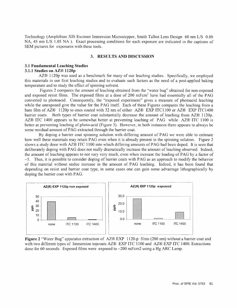
Figures 2 compares the amount of leaching obtained from the "water bug" obtained for non-exposedand exposed resist films. The exposed films at a dose of 200 mJ/cm2 have had essentially all of the PAGconverted to photoacid. Consequently, the "exposed experiment" gives a measure of photoacid leachingwhile the unexposed give the value for the PAG itself. Each of these Figures compares the leaching from abare film of AZ® 1 l2Op to ones coated with 32 nm of either AZ® EXP ITC1 100 or AZ® EXP ITC 1400barrier coats. Both types of barrier coat substantially decrease the amount of leaching from AZ® 1 l2Op.AZ® ITC 1400 appears to be somewhat better at preventing leaching of PAG while AZ® ITC 1 100 isbetter at preventing leaching of photo-acid (Figure 3). However, in both instances there appears to always besome residual amount of PAG extracted through the barrier coat.
By doping a banier coat spinning solution with differing amount of PAG we were able to estimatehow well these materials may retain PAG even when it is already present in the spinning solution. Figure 2shows a study done with AZ® ITC 1 100 into which differing amounts of PAG had been doped. It is seen thatdeliberately doping with PAG does not really dramatically increase the amount of leaching observed. Indeed,the amount of leaching appears to not vary very much, even when increase the loading of PAG by a factor of5. Thus, it is possible to consider doping of barrier coats with PAG as an approach to modify the behaviorof this material without undue increase in the amount of PAG leaching. Indeed, it has been found thatdepending on resist and barrier coat type, in some cases one can gain some advantage lithographically bydoping the barrier coat with PAG.
10.0
0.0none
Figure 2 "Water Bug" apparatus extraction of AZ® EXP 1 120-p films (200 nm) without a barrier coat andwith two different types of Immersion topcoats AZ® EXP ITC 1100 and AZ® EXP ITC 1400. Extractionsdone for 60 seconds. Exposed films were exposed to 200 mJ/cm2 using a Hg ARC Lamp.
AZ(R) EXP l120p non exposed
50
40
. 30aa 2010
0none ITO 1100 ITO 1400
30.0
20.0.caa
AZ(R) EXP 1120p exposed
ITO1100 1T01400
F
Proc. of SPIE Vol. 5753 81

- 300a 20
10
0
AZ(R) I l20p effect of PAG in Barrier Coat50
40
3.1.2 Effect of post-applied bake on immersion barrier coats.Table 1 shows the results of a headspace analysis study done using different types of barrier coats
and different types of spinning solvent (either alcohol or alkane based). These banier coats were appliedwith, or without, a post applied bake of 135°C for 90 seconds. This study revealed that, regardless of barriercoat matrix, type of spinning solvent, we did not detect any remaining solvent even when the film was notbaked at all.
Table 1 Heads ace Analysis of Remaining Solvents
Product Condition Solvent
Solvent RemainingDetection limit =0.1vt%
ITC-1 100 'IO BAKE Higher alcohol based Below detection limit
ITC-1100BAKED135/90 Higher alcohol based Below detection limit
ITC-1400 NO BAKE Higher alcohol based Below detection limit
ITC-1400BAKED135/90 Higher alcohol based Below detection limit
ITC-1300 NO BAKE Higher alcohol based Below detection limit
ZTC-1300BAKED135/90 Higher alcohol Below detection limit
ITC-1450 O BAKE Higher Alkane based Below detection limit
ITC-1450BAKED135/90 Higher Alkane based Below detection limit
3.1.3 Leaching studies on resist materials designed for Immersion lithography.Our initial studies with AZ® EXP 1 l2Op, a resist designed for dry lithography, allowed us to design
barrier coat materials which on actual immersion exposure gave a more optimum performance bothlithographically and in terms of the amount of leaching. In the next section will describe the lithographicportion of this study, but this final part of the leaching section will summarize some the leaching results fromdifferent types of resist we have designed for optimum performance using 193 nm immersion lithography.
none ITCilOOno ITC1100 ITC1IOO ITC 1100
PAG low PAG medium high PAGPAG
Figure 3 "Water Bug" apparatus extraction of AZ® EXP 1 120-p films (200 nm) without and with a thebarrier coat, AZ® EXP ITC 1 100, into which increasing amount of PAG are doped. Extractions done for 60seconds with distilled water.
82 Proc. of SPIE Vol. 5753
The resist studied were as follows: two L/S resist systems AZ® EXP IRC 1000 and AZ® EXP JIRC1500 and two contact hole resists AZ® IRC 2000 and AZ® IRC 1520.
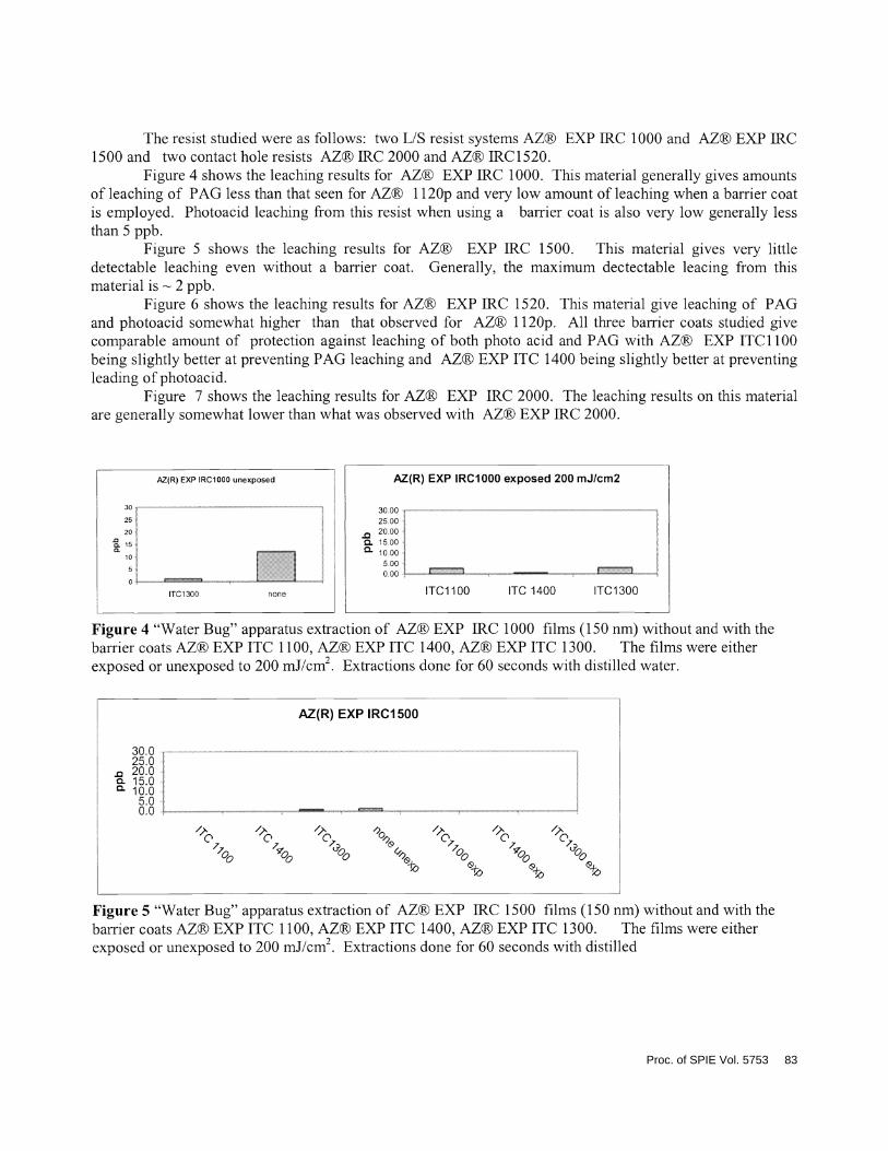
Figure 4 shows the leaching results for AZ® EXP IRC 1000. This material generally gives amountsof leaching of PAG less than that seen for AZ® ll2Op and very low amount of leaching when a barrier coatis employed. Photoacid leaching from this resist when using a barrier coat is also very low generally lessthan 5 ppb.
Figure 5 shows the leaching results for AZ® EXP IRC 1 500. This material gives very littledetectable leaching even without a barrier coat. Generally, the maximum dectectable leacing from thismaterial is 2 ppb.
Figure 6 shows the leaching results for AZ® EXP IIRC 1520. This material give leaching of PAGand photoacid somewhat higher than that observed for AZ® 1 l2Op. All three barrier coats studied givecomparable amount of protection against leaching of both photo acid and PAG with AZ® EXP ITC 1100being slightly better at preventing PAG leaching and AZ® EXP ITC 1400 being slightly better at preventingleading of photoacid.
Figure 7 shows the leaching results for AZ® EXP IRC 2000. The leaching results on this materialare generally somewhat lower than what was observed with AZ® EXP IIRC 2000.
Figure 4 "Water Bug" apparatus extraction of AZ® EXP TIRC 1000 films (150 nm) without and with thebarrier coats AZ® EXP ITC 1100, AZ® EXP ITC 1400, AZ® EXP ITC 1300. The films were eitherexposed or unexposed to 200 mJ/cm2. Extractions done for 60 seconds with distilled water.
Figure 5 "Water Bug" apparatus extraction of AZ® EXP IRC 1500 films (150 nm) without and with thebarrier coats AZ® EXP ITC 1100, AZ® EXP ITC 1400, AZ® EXP ITC 1300. The films were eitherexposed or unexposed to 200 mJ/cm2. Extractions done for 60 seconds with distilled
P2(R) EXP IRCI000 unexposed AZ(R) EXP IRCI000 exposed 200 mJ/cm2
30 30.0025 25.OO2O. .0 20.001
Q. 15.001Q. o . 10.00
5.00 _________________ 0 00
0
1TC1300 none ITC1100 ITO 1400 1TC1300
AZ(R) EXP IRCI 500
30.025.020.0
o. 15.0a 10.0
5.00.0
/,) /,) '2C C CC C C
00 0 00 00 7V& & &
Proc. of SPIE Vol. 5753 83

I!1[DL LIFigure 6 "Water Bug" apparatus extraction of AZ® EXP IRC 1520 films (1 50nm) without and with thebarrier coats AZ® EXP ITC 1 100, AZ® EXP ITC 1400, AZ® EXP ITC 1300. The films were eitherexposed or unexposed to 200 mJ/cm2. Extractions done for 60 seconds with distilledSimulated Immersion Studies with 1 l2Op
Figure 7 "Water Bug" apparatus extraction of AZ® EXP IRC 2000 films (150 nm) without and with thebarrier coats AZ® EXP ITC 1 100, AZ® EXP ITC 1400, AZ® EXP ITC 1300. The films were eitherexposed or unexposed to 200 mJ/cm2. Extractions done for 60 seconds with distilled
3.2 Exposure Studies with barrier coats3.2.1 Dry exposure studies with AZ® EXP ll2Op and barrier coats.
All the barrier coats AZ® EXP ITC 1400, AZ® EXP ITC1300 and AZ® EXP ITC1 100 wereevaluated under dry 193 nm exposures with a Nikon 306D 193nm scanner on films of AZ® 1 l2Op. Thebarrier coat thickness for these evaluations is 32 nm while the resist thickness is 200 nm. Under theseconditions, the resist without barrier coat for 100 nm 1 : 1 L/S features gives a depth of focus of 1 micronand a dose latitude of —5 mJ/cm2 (+-1O% of coded size). The use of most barrier coats does not significantlyalter the performance of the reference material AZ® 1 l2Op. These evaluations are done with a linkedexposure tool and track. If exposures are done in a non-linked state, where the exposed wafer is handcarried from the track to exposure tool, the performance of AZ® 1 l2Op alone or coated with AZ® EXPITC 1400 or AZ® EXP ITC 1300, the performance is also not affected by possible amine contamination.However, AZ® EXP ITC 1 100 coated on AZ® 1 l2Op does impart some sensitivity to amine contamination.Figure 10 illustrates the type of webbing that is typically seen at the edge of dose latitude under conditions ofamine contamination. This webbing typically occurs at the edge of dose latitude and may cut it by 2 mJ/cm2.This impact on the PED delay stability of AZ® 1 l2Op is probably caused both by the depletion of PAGbrought about by casting the barrier coat on top of the resist coupled with the apparently poor performance ofAZ® EXP ITC 1 100 as an amine barrier coat. As was previously discussed, in the section on leaching, theaddition of PAG to barrier coat formulations does not greatly increase the amount of PAG leaching evenwhen using a high loading of PAG in the barrier coat. Consequently, since the generation of acid in thebarrier coat could help to counteract the loss of PED latitude on this system, a PAG was added to the standardformulation of AZ® EXP ITC1 100. Figures 8, 9, 10 and 11 illustrate the exposures done of AZ® 1 l2Op in
AZ(R) EXP 1RC1520 unexposed
ITC1100 ITC1400 ITC1300 none
AZ(R) EXP 1RC1520 exposed 200 mJ/cm2
ITC1400 ITC1300
ri101100
AZ(R) EXP IRC2000 unexposed
30.00
25.002000
-a 15.00l000500.000 . .
1101100 101400 1101300 none
AZ(R) EXP IRC2000 exposed 200 mJ/cm2
30.0025.0020.00
-a 15.00 ..0.10.00Ir:: e=
101100 101400 1101300
84 Proc. of SPIE Vol. 5753

which, respectively, AZ® EXP ITC 1100 is doped with a high, medium and low concentration of a PAG.The results of this study indicate that the use of a high or medium concentration of PAG is effective inreestablishing the PED latitude of the material deleteriously affected by the application of AZ® EXP ITC1 100 without any PAG. Interestingly, it is seen that a low loading of PAG in AZ® EXP ITC 1100 gives thesame type of webbing problem. This would indicate that there is a certain threshold amount of PAG neededto enable protection against airborne amines under strenuous conditions. It should be emphasized that thisphenomenon is not seen under normal operating conditions with a linked track, but only when the wafers areexposed to the relatively high airborne contamination during a hand carry transfer between exposure andtrack.
31.OmJ 32.OmJ
S.::55555 ...... .. :• ...,===aas
Figure 8 AZ® 1 l2Op (200 nm) coated with AZ® ITC 1100 (32 nm). Exposures done with non-linkedtrack and Nikon exposure tool(see experimental) The AZ® EXP ITC 1 100 sample was not doped withPAG.
27.0 mJ 28.0 mJ
:!Figure 9 AZ® I l2Op (200 nm) coated with AZ® ITC 1100 (32 nm). Exposures done with non-linked trackand Nikon exposure tool(see experimental) The AZ® EXP ITC 1 100 sample was doped with a high PAGconcentration.
30.OmJ 31.OmJasFigure 10 AZ® 1 l2Op (200 nm) coated with AZ® ITC 1 100 (32 nm). Exposures done with non-linkedtrack and Nikon exposure tool(see experimental) The AZ® EXP ITC 1 100 sample was doped with amedium PAG concentration.
29 0 mJ 30.0 mJ
k*%&4
4? 44
*& *aFigure 11 AZ® ll2Op (200 nm) coated with AZ® ITC 1100 (32 nm). Exposures done with non-linkedtrack and Nikon exposure tool(see experimental) The AZ® EXP ITC 1 100 sample was doped with a lowPAG concentration.
Proc. of SPIE Vol. 5753 85
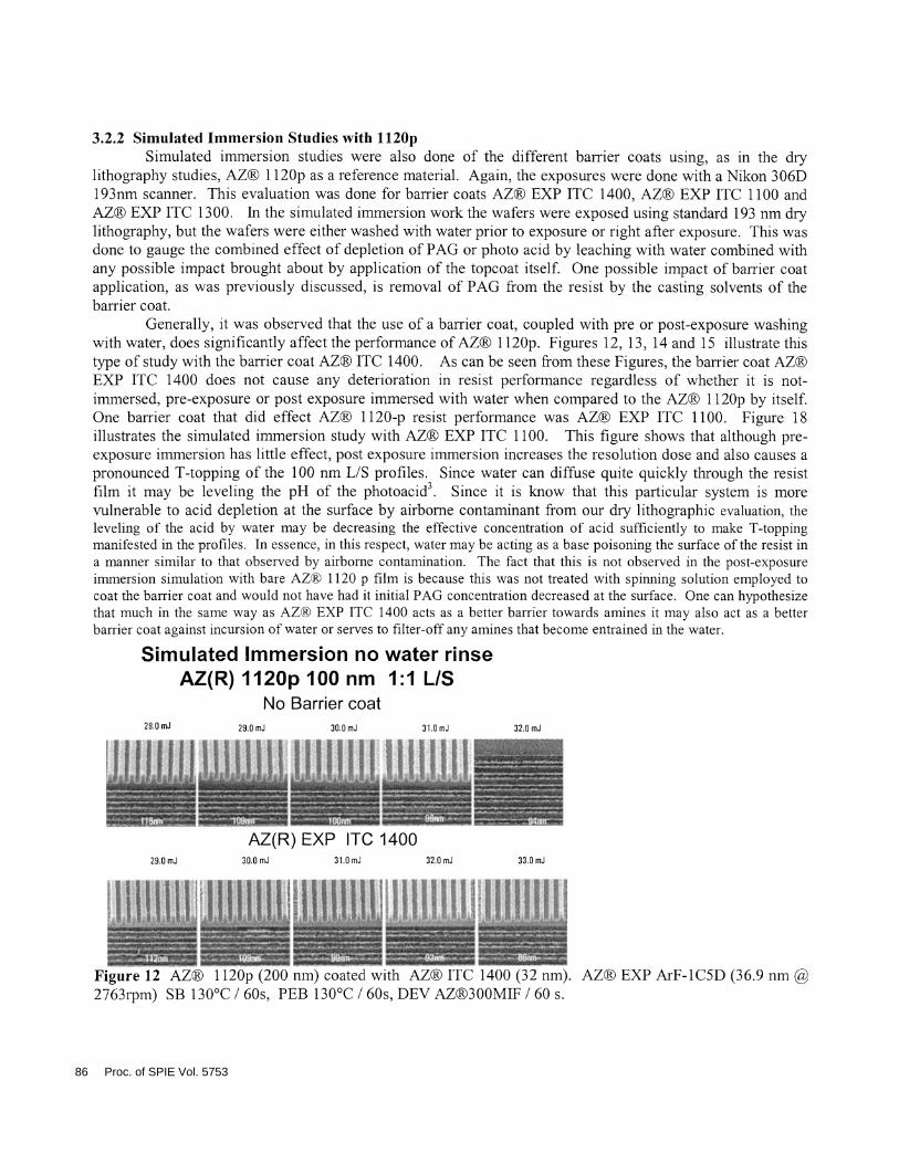
3.2.2 Simulated Immersion Studies with ll2OpSimulated immersion studies were also done of the different barrier coats using, as in the dry
lithography studies, AZ® 1 l2Op as a reference material. Again, the exposures were done with a Nikon 306D193nm scanner. This evaluation was done for barrier coats AZ® EXP ITC 1400, AZ® EXP ITC 1100 andAZ® EXP ITC 1 300. Tn the simulated immersion work the wafers were exposed using standard 193 nm drylithography, but the wafers were either washed with water prior to exposure or right after exposure. This wasdone to gauge the combined effect of depletion of PAG or photo acid by leaching with water combined withany possible impact brought about by application of the topcoat itself. One possible impact of barrier coatapplication, as was previously discussed, is removal of PAG from the resist by the casting solvents of thebarrier coat.
Generally, it was observed that the use of a barrier coat, coupled with pre or post-exposure washingwith water, does significantly affect the performance of AZ® 1 1 2Op. Figures 1 2, 1 3 , 1 4 and 1 5 illustrate thistype of study with the barrier coat AZ® ITC 1400. As can be seen from these Figures, the barrier coat AZ®EXP ITC 1400 does not cause any deterioration in resist performance regardless of whether it is not-immersed, pre-exposure or post exposure immersed with water when compared to the AZ® 1 l2Op by itself.One barrier coat that did effect AZ® 1 120-p resist performance was AZ® EXP ITC 1 100. Figure 18illustrates the simulated immersion study with AZ® EXP ITC 1 100. This figure shows that although pre-exposure immersion has little effect, post exposure immersion increases the resolution dose and also causes apronounced T-topping of the 100 nm L/S profiles. Since water can diffuse quite quickly through the resistfilm it may be leveling the pH of the photoacid3. Since it is know that this particular system is morevulnerable to acid depletion at the surface by airborne contaminant from our dry lithographic evaluation, theleveling of the acid by water may be decreasing the effective concentration of acid sufficiently to make T-toppingmanifested in the profiles. In essence, in this respect, water may be acting as a base poisoning the surface ofthe resist ina manner similar to that observed by airborne contamination. The fact that this is not observed in the post-exposureimmersion simulation with bare AZ® 1120 p film is because this was not treated with spinning solution employed tocoat the barrier coat and would not have had it initial PAG concentration decreased at the surface. One can hypothesizethat much in the same way as AZ® EXP ITC 1400 acts as a better barrier towards amines it may also act as a betterbanier coat against incursion of water or serves to filter-off any amines that become entrained in the water.
Simulated Immersion no water rinseAZ(R) 1120p 100 nm 1:1 LIS
No Barrier coat28.0 mJ 29.0 mJ 30.0 nJ 31.0 nJ 32.0 mJ
=== ? 4 4: .::.:..
4....:.:.............:.....:::.:::. ..........:: . •.•...•:•.•.... : .
AZ(R)EXP ITC 140029.0 mJ 30.0 mJ 31.0 mJ 32.0 mJ 33.0 mJ
4 % *888$, . - - .:Figure 12 AZ® 1 l2Op (200 nm) coated with AZ® ITC 1400 (32 nm). AZ® EXP ArF-1C5D (36.9nm2763rpm) SB 130°C I60s, PEB 130°C I 60s, DEV AZ®300MIF I60 s.
86 Proc. of SPIE Vol. 5753

Simulated Immersion pre exposure water rinseAZ(R) ll20p 100 nm 1:1 LIS
No Barrier coat28OmJ 29.OmJ 30.OmJ 31.OmJ 32.OmJ
0 Vø *s4SS&U 4 44M n wfl4fl % nmuw_ %Ø fl %. :. .fl4$*8%4t Sb tM JWtt aa< :; ..
AZ(R) EXP ITO 140029.0 mJ 30.0 mJ 31.0 mJ 32.0 mJ 33.0 mJ
&na a4w 4
Figure 13 AZ® I l2Op (200 nm) coated with AZ® ITC 1400 (32 nm). AZ®' EXP ArF-1C5D (36.9 nm2763rpm) SB 130°C I 60s, PEB 130°C I 60s, DEV AZ®300MTF I 60 s. Pre exposure rinse with DI wateriminute.
Simulated Immersion post exposure water rinseAZ(R) 1l20p 100 nm 1:1 LIS
No Barrier coat27.0 mJ 28.0 mJ 29.0 mJ 30.0 mJ 31.0 mJ
4 4 4a 4% 4 a&&áa U# 4SS a as 1SM&S *thM M4 * 14 h#a4 *m 44 A4* a4 4*'4 *&tw sss# 484 4 4 4 a* 4th4* 4s44 #1 44 d #fl t 4* 4g& 44 44< fl 4'4 fl —
4 48# 8& #fl 4i$t4a4 4 4s&* L #4d fl 44'4 4s4 4$ 4t4 4f flt*€ a44a##4#4'4*44'#
AZ(R) EXP ITO 140027.0 mJ 28.0 mJ 29.0 mJ 30.0 mJ 31.0 mJ
dgaSsa44 aa tW ssaM 4 OSM4 Ja*44$aa$*4886#sa$8B&& 444fl4's ' 'A " 44&# &*%$4' 4444 $4 '44'$4* 44a4'
.. I '$$$ $ssS a S s S 4$$&a $a 4$$e$ 4$ns
Figure 14 AZ® I hOp (200 nm) coated with AZ® ITC 1400 (32 nm). AZ® EXP ArF-1C5D (36.9 nm2763rpm) SB 130°C 1 60s, PEB 130°C I 60s, DEV AZ®300MIF I 60 s. Post exposure rinse with DI wateriminute.
Proc. of SPIE Vol. 5753 87
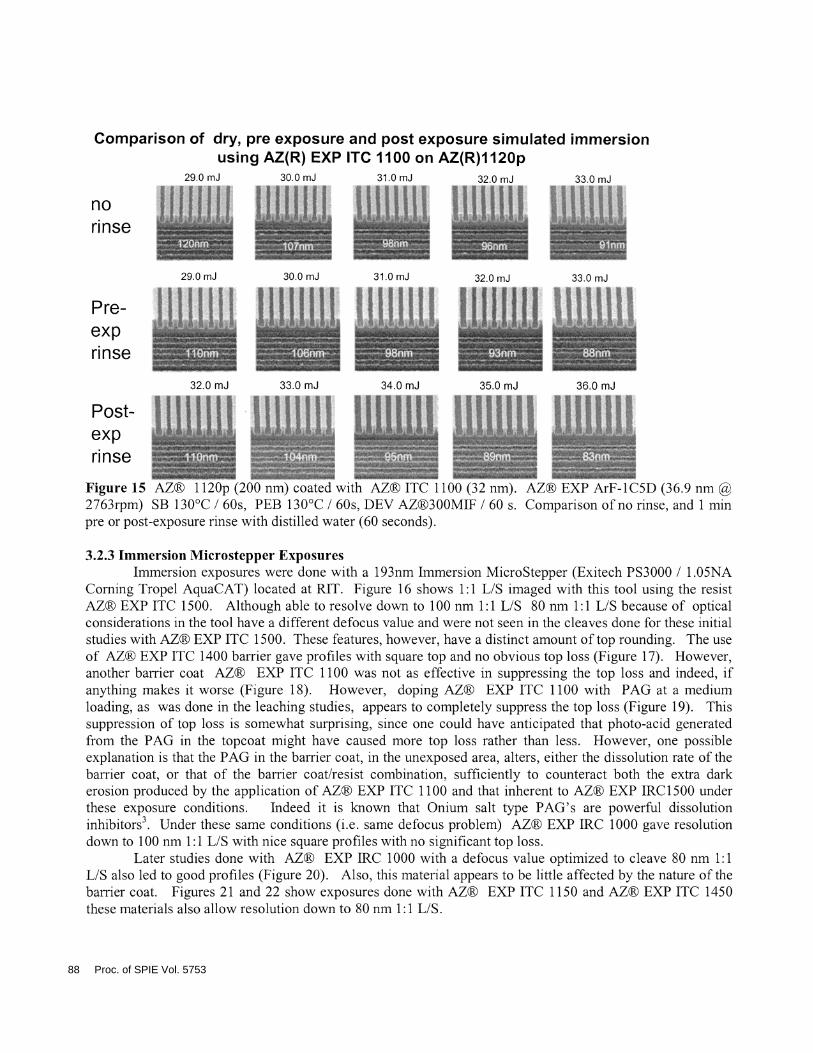
Comparison of dry, pre exposure and post exposure simulated immersionusing AZ(R) EXP ITC 1100 on AZ(R)1120p
29.0 mJ 30.0 mJ 31.0 mJ 320 mJ 33.0 mJ
nor i n se $ _________
29.0 mJ 30.0 mJ 31.0 mJ 32.0 mJ 33.0 mJ
Pie-e x prirI I I I % & d$ 88 4
4 4 ' 4 4
32.0 mJ 33.0 mJ 34.0 mJ 35.0 mJ 36.0 mJ
Post-ex p 444#
rinse4 444
Figure 15 AZ® I l2Op (200 nm) coated with AZ® ITC 1 100 (32 nm). AZ® EXP ArF-1C5D (36.9 nm2763rpm) SB 130°C I 60s, PEB 130°C I 60s, DEV AZ®300MIF I 60 s. Comparison ofno rinse, and 1 mmpre or post-exposure rinse with distilled water (60 seconds).
3.2.3 Immersion Microstepper ExposuresImmersion exposures were done with a 193nm Immersion MicroStepper (Exitech P53000 I 1 .O5NA
Coming Tropel AquaCAT) 'ocated at RIT. Figure 16 shows 1 : 1 L/S imaged with this toot using the resistAZ® EXP ITC 1500. Although able to resolve down to 100 nm 1 : 1 L/S 80 nm 1 : 1 LIS because of opticalconsiderations in the tool have a different defocus value and were not seen in the cleaves done for these initialstudies with AZ® EXP ITC 1 500. These features, however, have a distinct amount of top rounding. The useof AZ® EXP ITC 1400 barrier gave profiles with square top and no obvious top loss (Figure 17). However,another barrier coat AZ® EXP ITC 1 100 was not as effective in suppressing the top loss and indeed, ifanything makes it worse (Figure 1 8). However, doping AZ® EXP ITC 1 100 with PAG at a mediumloading, as was done in the leaching studies, appears to completely suppress the top loss (Figure 19). Thissuppression of top loss is somewhat surprising, since one could have anticipated that photo-acid generatedfrom the PAG in the topcoat might have caused more top loss rather than less. However, one possibleexplanation is that the PAG in the barrier coat, in the unexposed area, alters, either the dissolution rate of thebarrier coat, or that of the barrier coat/resist combination, sufficiently to counteract both the extra darkerosion produced by the application of AZ® EXP ITC 1100 and that inherent to AZ® EXP IRC1500 underthese exposure conditions. Indeed it is known that Onium salt type PAG's are powerful dissolutioninhibitors3. Under these same conditions (i.e. same defocus problem) AZ® EXP IRC 1000 gave resolutiondown to 100 nm 1 :1 L/S with nice square profiles with no significant top loss.
Later studies done with AZ® EXP IRC 1000 with a defocus value optimized to cleave 80 nm 1:1L/S also led to good profiles (Figure 20). Also, this material appears to be little affected by the nature of thebarrier coat. Figures 21 and 22 show exposures done with AZ® EXP ITC 1 150 and AZ® EXP ITC 1450these materials also allow resolution down to 80 nm 1 : 1 L/S.
88 Proc. of SPIE Vol. 5753

65 mJ/cm2
62mJ/cm2
59 mJ/cm2
56 mJ/cm2
53 mJ/cm2
50 mJ/cm2
4Sss
//
*t-&---'4- -*--a—
l4Onm l2Onm lOOnm
e
S
S
Figure 17 AZ(R) EXP IRC 1500 (100 nm), AZ(R) EXP ITC 1400(32 nm) PAB:130°C/60s PEB1O5°C/60s,
Develop 60 sAZ(R) 1C5D (37 nm)
Figure 16 AZ(R) EXP IRC 1500 (100 nm),No Barrier Coat. PAB: 130°C/60s PEB1O5°C/60s, Develop 60 sAZ(R) 1C5D (37 nm)
74 mJ/cm
71 mJ/cm2
68mJ/cm2
65 mJ/cm2
62 mJ/cm2
59 mJ/cm2
140 nm 120 nm 100
Proc. of SPIE Vol. 5753 89

::.:::.%::::::.:..:.;..:.:.:.:.:.:.::.:::. . .:::::.:.: • ..:::.:.:..:.:.::
140 nm
81 mJ/cm2
78mJ/cm2
75 mJ/cm2
72 mJ/cm2
l4Onm l2Onm lOOnmFigure 18 AZ(R) EXP IRC 1 500 (1 00 nm), AZ(R) EXP ITC 1 1 00(32 nm) PAB: 1 30°C160s PEB1 05°C/60s,
Develop 60 sAZ(R) 1C5D (37 nm)
68 mJ/cm2
65 mJ/cm2
62mJ/cm2
59 mJ/cm2
56 mJ/cm2
Figure 19 AZ(R) EXP IRC 1500 (100 nm), AZ(R) EXP ITC 1 1 00(32 nm) doped with medium loading ofPAG, PAB: 1 3OoC/60s PEB 1 O5oC/60s, Develop 60 sAZ(R) 1 C5D (37 nm)
l2Onm lOOnm
90 Proc. of SPIE Vol. 5753

65mJ/cm2,SSSS"Sn ;::' iS
5, ,,7, : 1 Sl4Onm l2Onm lOOnm 9Onm 8Onm
Figure 20 AZ(R) EXP IRC 1000 (100 nm), no banier coat, PAB:130°C/60s PEB1O5°C/60s, Develop 60 sAZ(R) 1C5D (37 nm)
VjsA&as ,.
W4ssa 4&4&44th *sS4sa
;:
I e' 4$?); r f,/ Alinaisv #S k aa*s
nnnsa9Onm
68 mJ/cm2
65.0 mJ/cm2
62.5 mJ/cm2
60.0 mJ/cm2
57.5. mJ/cm
55.0. mJ/cm
100 nm 8OnmFigure 21 AZ(R) EXP IRC 1000 (100 nm), AZ(R) EXP ITC 1150 (32 nm), PAB:l3OoC/60sPEB1O5oC/60s, Develop 60 sAZ(R) 1C5D (37 nm)
Figure 22 AZ(R) EXP IRC 1000 (100 nm), AZ(R) EXP ITC 1450 (32 nm), PAB:130°C/60s PEB1O5°C/60s,
Develop 60 s AZ(R) 1C5D (37 nm)
Proc. of SPIE Vol. 5753 91

3.2.4 Immersion Interferometric exposuresOur initial interferometric immersion were done on a custom built tool operating at 21 3 nm located at
UNM. The initial screening work was done with an early prototype resist AZ® EXP M3000. This materialwhen subjected to immersion was particularly sensitive to airborne contamination. Presumably, this occursbecause of either PAG and/or photoacid depletion in the surface of this resist leading to a loss of post-exposure bake latitude. This same problem led to imaging difficulties with this material in our 193 nmmicrostepper exposure at RIT. Figure 23 shows some relaxed pitches shot using 2 1 3 nm interferometricimmersion lithography. When no barrier coat is present, the profiles show distinct sighs of T-topping.Similarly, when using AZ® EXP ITC 1 100 distinct T-topping is seen (Figure 23). The other barrier coatsbased on more heavily fluorinated materials (AZ® EXP ITC 1400, AZ® EXP ITC 1450, AZ® EXP ITC1300, AZ® EXP ITC 1350) all show less T-topping. The best barrier coats from this stand point are AZ®EXP ITC 1400, AZ® EXP ITC 1300 and AZ® EXP ITC 1350. Although not shown here, the addition ofPAG to AZ® EXP ITC 1 100 can help to remove the T-topping. Presumably, in this instance, the extra acidproduced by the PAG in the exposed barrier coat is having a greater effect. Under these conditions, theresist AZ® EXP ITC 1500 which had shown top loss when not protected by a top coat during the 193 nmimmersion microstepper exposure shows images with nice straight wall profiles. Furthermore, the use of thebarrier coat AZ® EXP ITC 1 100 and AZ® EXP ITC 1400 maintains the image quality (Figure 24). Theresist AZ® EXP IRC1000 which gave nice straight wall profiles with no top loss when exposed on the 193nm immersion microstepper at RIT here give L/S feature with a slight T-top. However, this same barriercoat/resist combination when applied to 80 nm contact hole resolution give to much better contact holeuniformity (Figure 25) than the resist without the barrier coat.
*< \ s* i\\ t $ .\ \ 4&
No Barrier Coat ITC I 100 ITC 1350 ITC 1450CD=56nm CD=58nm CD=38nm CD=42nm
4
—
tS!!1sITC 1300 ITC 1400
CD=4Onm CD=47nm
Figure 23 L/S features imaged with an r tool at 213 nm BARC: ARC28-4 @21 16 RPM FT34nm, BARCHard Bake: 215°C 60" Contact Hotplate Coat: AZ(R) M3000 FT lOOnm @ 3285RPM Barrier coat thickness32 nm. Soft Bake: 130°C 60" Contact Hotplate Exposure Medium: DI H20 (n=1.42) NA=1.17 ExposureTime: 30 sec. 1 = 213nm PEB: 120°C 60" Contact Hotplate Develop: 60" Puddle Develop CD-26 DI Rinse:10" + Surfactant Rinse 3"
92 Proc. of SPIE Vol. 5753

No Tarp AZ(R) EXP ITC1 100 AZ(R) EXP ITC1400CD=47nm CD=54nm CD=48nm
Figure 24 L/S 1:1 features imaged with an interferometrie tool at 213 nm BARC: ARC28-4 @2116 RPMFT'-i4nm, BARC Hard Bake: 215°C 60" Contact Hotplate Coat: AZ(R) EXP IRC 1500 FT lOOnm Barriercoat thickness 32 nm. Soft Bake: 130°C 60" Contact Hotplate Exposure Medium: DI H20 (n=1.42)NA=1.17 Exposure Time: 30 sec. 1 213nm PEB: 120°C 60" Contact Hotplate Develop: 60" PuddleDevelop CD-26 DI Rinse: 10" + Surfactant Rinse 3"
, ) :%t :;
, S:: •w4(,' *q
rigiIri m0' RI)r - 25 55 nm L/S (ir; and _ nm Cr{(bottom) imaged with an interferometric tool at 213 nm. AZ®EXP IRC 1000 (100 nm) Left : no barrier coat, Right: AZ® EXP ITC 1400(32 nm Soft Bake: 130°C 60"Contact Hotplate, Exposure medium: HPLC H20 (n=1.42) NA=.81, Exposure Time: 36 sec 1 = 213nm,PEB: 105°C 90" Contact Hotplate Develop: 60" Puddle Develop CD-26, DI Rinse: 10" + Surfactant Rinse 3"
Finally, Figure 25 shows SEM pictures for interferometric immersion lithography done at 193 nmat the MT (Amphibian XIS Excimer Immersion Microstepper,). These pictures were taken with acombination of AZ(R) EXP 1TC1450 barrier coat with AZ(R) EXP IRC 1000 resist. In this manner it waspossible to get very good resolution of 65 1 : 1 L/S features and resolution, with some top loss, of 45 nm 1:1L/S features.
Figure 26 45 (left) 55%- and ( (right) nm 1 : 1 L/S Imaged with Amphibian XIS Excimer ImmersionMicrostepper AZ(R) EXP ITC145O (32 nm) AZ(R) EXP IRC 1000 (100 nm), AZ(R) EXP UBB1-45(45 nm)AZ(R) EXP LBB1-32 (32 nm).PAB:l3OoC/60s PEB1O5oC/60s, Puddle Develop 60 s.
4. CONCLUSIONIn our studies of leaching and headspace analysis, we have found that using a post-applied bake is not
needed to remove solvent. All the barrier coats we have evaluated by leaching (AZ(R) EXP ITC 1100,
1.3ar.r.e.r (
Proc. of SPIE Vol. 5753 93
AZ(R) EXP ITC 1400 and AZ(R) EXP ITC 1300) are effective in decreasing loss of PAG and/or photoacidby teaching with water.
The barrier coats have a good capability to retain PAG, and extra PAG added to the barrier coatformulation does not greatly increase the amount of PAG leached from the resist surface.
Leaching measurements on resist designed for 193 nm immersion AZ(R) EXP IRC1000, AZ(R) EXPIRC 1 500, AZ(R) EXP 1 520 and AZ(R) EXP 2000 show that these materials have less detectable leaching ingeneral than a more conventional dry resist such as AZ® 1 l2Op.
Dry and Simulated Immersion studies show that barrier coats have no effect on performance ofAZ(R) 1 l2Op except for some T-topping seen in simulated post exposure immersions, or when exposure toairborne contaminants occurs using AZ(R) EXP ITC 1 100 barrier coat.
Microstepper Immersion Lithography done using the AquaCAT tool at RIT show that for AZ®EXP 1IPC 1000, AZ® EXP ITC 1400 reestablishes square profiles while the use of AZ® ITC 1000 makestop loss even worse. It appears that adding PAG to a formulation of AZ® ITC 1 100 also gives rises to L/Sprofiles with far less top loss. Experiments down with AZ® IRC 1000 shows that the barrier coats do notsignificantly impact the good performance of this material.
Interferometric Lithography done at 213 nm at UNM show that under conditions with no protectionagainst amine contamination AZ® EXP ITC 1 300, AZ® EXP ITC 1400, AZ® EXP ITC 1 350, gave thebest suppression of T-topping evident in a prototype resist AZ® EXP M3000. Again AZ® ITC 1100 gavea large amount of T-topping. The use of the more mature resist materials such as AZ® EXP IRC 1000 andAZ® IRC 1500 gives little negative effect on imaging of the barrier coats. Indeed for AZ® IRC 1000contact hole uniformity (80 nm) is greatly improved by the use of AZ® EXP ITC 1400.
Interferometric Lithography done at 193 nm at RIT (193) shows good resolution of 65 nm 1:1 L/Sand partial imaging of45 nm L/S when using AZ® EXP IRC 1000 protected with AZ® EXP ITC 1450.
It appear that the effect of barrier coat on imaging is a complex interweaving of the effect of PAG andphotoacid leaching by water, the effect of application of the barrier coat, the nature of barrier coat itself on theimaging capability of the resist, and in these early experiments the effect of amine contamination on a resistsystem which has already been impacted by having its active components depleted by water immersion or bythe application of the barrier coat itself.
5. ACKNOWLEDGMENTSThe authors would like to International SEMATECH for use of the Imaging facilities at the RochesterInstitute of Technology. The authors would are also very grateful for the assistance provided by Prof BruceSmith, Emil Piscani and James Park at the Rochester Institute of Technology.
6 REFERENCES1. "Immersion lithography and its impact on semiconductor manufacturing," Burn J. Lin, Optical Microlithography
XVII, edited by Bruce W. Smith, page 46 Proceedings of SPIE Vol. 5377 (SPIE, Bellingham, WA, 2004)2. "Immersion Liquids for Lithography in the Deep Ultraviolet,M. Switkes*, R. R. Kunz, R. F. Sinta, M.
Rothschild, P. M. Gallagher-Wetmore, V. J. Krukonis, K. Williams"Optical Microlithography XVI, AnthonyYen, Editor, Proceedings ofSPIE, page 690 Vol. 5040 (2003) 2003 SPIE . 0277-786X/03/$ 15.00
3. "A study on the dissolution inhibition ofpoly norbornene hexafluoroisopropanol in aqueous base solutions" M.Toukhy, J. Oberlander, D. Rahman, F. Houlihan, Advances in Resist Technology and Processing XXI, edited byJohn L. Sturtevant, page 384, Proceedings of SPIE Vol. 5376 (SPIE, Bellingham, WA, 2004)
4. The bilayer BARCs employed in this paper are described in "Bilayer BARC' s for 193 nm ImmersionLithography," DJ Abdallah, J.J. Biafore, A Raub, F.M. Houlihan, M Neisser, G. Pawlowski, S. Ding,Proceeding of SPIE 2005 in press
94 Proc. of SPIE Vol. 5753
Copyright © 2022 FDOKUMEN