Effectiveness of replacing catalytic converters in LPG-fueled ...
November 2002 MODULATION TECHNIQUES COMPARISON FOR THREE LEVELS VSI CONVERTERS
1
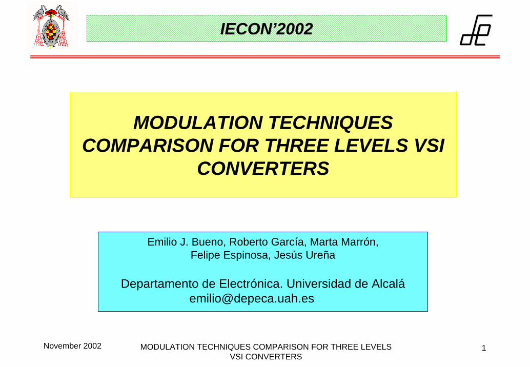
MODULATION TECHNIQUES COMPARISON FOR THREE LEVELS VSI
CONVERTERS
Emilio J. Bueno, Roberto García, Marta Marrón,Felipe Espinosa, Jesús Ureña
Departamento de Electrónica. Universidad de Alcalá[email protected]
IECONIECON’’20022002

November 2002 MODULATION TECHNIQUES COMPARISON FOR THREE LEVELS VSI CONVERTERS
2
IndexIndex
1. Introduction.
2. PWM modulation techniques for NPC converters.
3. NP unbalancing in NPC.
4. Simulation results.
5. Conclusions.

November 2002 MODULATION TECHNIQUES COMPARISON FOR THREE LEVELS VSI CONVERTERS
3
RED ELÉCTRICA MÁQUINA ACASÍNCRONA
INVERSOR 2
Vw
Vu
Vv
Iw
Iv
Iu
VN
VNP
VP
Vc
Vb
Ic
Va
Ib
Ia
D2
D1
NP
C
C
Sa2
Sa1
Sa2
Sa1
Sb2
Sb1
Sb2
Sb1
Sc2
Sc1
Sc2
Sc1
N
P
IM
A/DMedida de variables
Control inversor 1.Generación señales SVPWM
A/DMedida de variables
A/DMedida de variables
Control inversor 2.Generación señales SVPWM
CPU principal
INVERSOR 1
NPC double converter block diagram
1. 1. Introduction Introduction (1/3)(1/3)

November 2002 MODULATION TECHNIQUES COMPARISON FOR THREE LEVELS VSI CONVERTERS
4
Comparison between a NPC VSI and a two-level VSI
1. 1. Introduction Introduction (2/3)(2/3)
2 levels 3 levels
UDC (V) 484,62 483,14IDCBUS (A) 17,395 17,241PDC (W) 8430 8330Pout activa (W) 8132,4 7992,3Pinv = PDC – Pout activa (W) 297,6 337,7
PIGBT (W) 49,6 28,14
2-level VSI line voltage
NPC VSI line voltage
• Load: R =1Ω y L = 10mH
• fS = 1Khz
Harmonics to the conmutation frequency

November 2002 MODULATION TECHNIQUES COMPARISON FOR THREE LEVELS VSI CONVERTERS
5
Diode rectifier/NPC inverter system: System used to simulate
L R
D 2
D 1 NP
C
C
Sa2
Sa1
Sa2
Sa1
Sb2
Sb1
Sb2
Sb1
Sc2
Sc1
Sc2
Sc1
N
P
VP
VN
INP
The simulations have been developed with the Matlab Power System Blockset
• Line voltage 400V/50Hz
• C = 4700μF
• IGBT’s are simulated by ideal- switches.
• R = 0.01Ω and L = 0.01H
1. 1. Introduction Introduction (3/3)(3/3)

November 2002 MODULATION TECHNIQUES COMPARISON FOR THREE LEVELS VSI CONVERTERS
6
Cosinusoidal modulation function (1/3)
( )αcos=OF
Sa1’scarrier
Sa2’scarrier
Reference signal
2. PWM2. PWM modulation techniques formodulation techniques for NPC NPC convertersconverters (1/8).(1/8).
Harmonic components of vab.
November 2002 MODULATION TECHNIQUES COMPARISON FOR THREE LEVELS VSI CONVERTERS
7
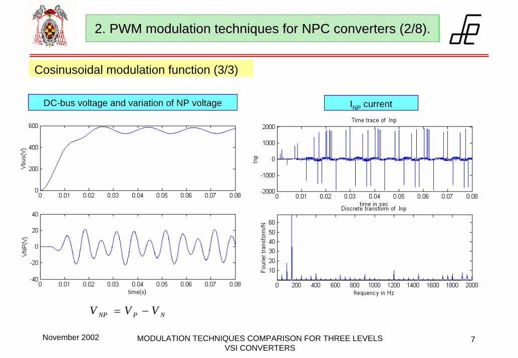
Cosinusoidal modulation function (3/3)
DC-bus voltage and variation of NP voltage INP current
NPNP VVV −=
2. PWM2. PWM modulation techniques formodulation techniques for NPC NPC convertersconverters (2/8).(2/8).
November 2002 MODULATION TECHNIQUES COMPARISON FOR THREE LEVELS VSI CONVERTERS
8
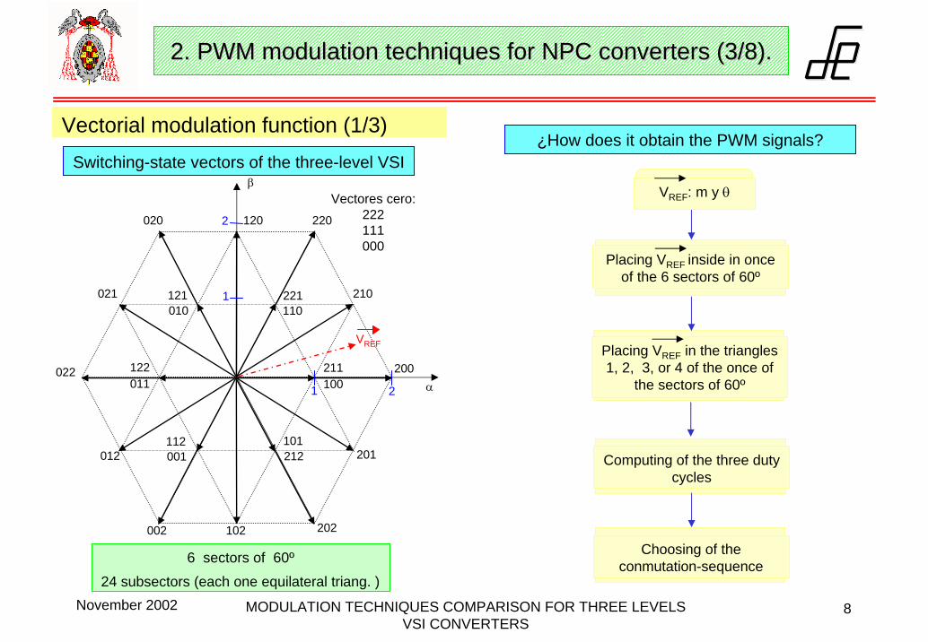
Vectorial modulation function (1/3)Switching-state vectors of the three-level VSI
6 sectors of 60º
24 subsectors (each one equilateral triang. )
201
α
β
220
210
200
202102002
012
022
021
020 120
211100
101212
112001
122011
121010
221110
VREF
21
1
2
Vectores cero:222111000
¿How does it obtain the PWM signals?
Placing VREF inside in once of the 6 sectors of 60º
Placing VREF in the triangles1, 2, 3, or 4 of the once of
the sectors of 60º
Computing of the three dutycycles
Choosing of the conmutation-sequence
VREF: m y θ
2. PWM2. PWM modulation techniques formodulation techniques for NPC NPC convertersconverters (3/8).(3/8).

November 2002 MODULATION TECHNIQUES COMPARISON FOR THREE LEVELS VSI CONVERTERS
9
200100
d11 d03d13
211
221110
VREF
220
210
4
213
θ
d01
d21
d04 d14
d24
d23
d02
d12
( ) ( )( )( ) ( )( )
( )θθθ
θθ
sin2sincos3
sincos31
21
11
01
⋅⋅=−⋅⋅=
+⋅⋅−=
mdmd
md
( )( ) ( )( )
( ) ( )( )θθ
θθ
θ
cos3sin1
cos3sin1
sin21
22
12
02
⋅−⋅+=
⋅+⋅+−=
⋅⋅−=
md
md
md
( ) ( )( )( ) ( )( )
( )θθθ
θθ
sin2sincos31
sincos32
23
13
03
⋅⋅=−⋅⋅+−=
−⋅⋅−=
mdmd
md
( ) ( )( )( ) ( )( )( )θ
θθ
θθ
sin21sincos32
sincos3
24
14
04
⋅⋅+−=+⋅⋅−=
−⋅⋅=
mdmd
md
1.-
2.-
3.-
4.-
( ) ( )θθ sincos31+⋅
<m
( ) ( )θθ sincos31+⋅
>m
( ) ( )θθ sincos31−⋅
>m
( )θsin21
⋅<m
¿In which subsector is the reference vector?
1. The reference vector is placed inside una de las 6 regiones de 60º.
2. How m is equal to:
se obtiene el subsector en el que está. 3
35.13
LL
REF
DC
REF
VV
VV
m⋅
==
Space-vectors for 0 θ60º (phase volltages)
200211100
221110
VREF
220
210
4
21 3
DCV⋅31
DCV⋅3
1
DCV⋅32
θ
Vectorial modulation function (2/3): VREFsynthesis3. Duty cycles calculation
2. PWM2. PWM modulation techniques formodulation techniques for NPC NPC convertersconverters (4/8).(4/8).

November 2002 MODULATION TECHNIQUES COMPARISON FOR THREE LEVELS VSI CONVERTERS
10
Vectorial modulation function (4/5): Conmutation sequence
0
1
2
0
1
2
0
1
2
c
b
a
100 200 210 211d0 d1 d2 d0
20d
20d
1d 2d
0
1
2
0
1
2
0
1
2
c
b
a
100 100 200 210d0 d0 d1 d2
2d0d 1d
ia
ib
ic
INP
VNP
P
N
Sa
Sb
Sc
O
C
C
a
b
c0
12
0
12
0
12
0
1
2
0
1
2
0
1
2
c
b
a
100 200 210 211d0 d1 d2 d0
40d
20d
21d
22d
20d
22d
21d
211d0
210d2
200d1
100d0
Example: VREF is in the subsector 3 of the first sector of 60º. Inside of this subsector there is one conmutation sequence:
100-200-210-211
After choose the conmutation sequence, the PWM signals are obtained.
Chosen option: Symmetrical PWM
Asymmetrical modulation Asymmetrical modulation withour 1 con.
Symmetrical
Modulation
2. PWM2. PWM modulation techniques formodulation techniques for NPC NPC convertersconverters (5/8).(5/8).

November 2002 MODULATION TECHNIQUES COMPARISON FOR THREE LEVELS VSI CONVERTERS
11
Vectorial modulation function (3/3): Results
Line voltage signal and its harmonic components
VREF (phase voltage)
Out line voltage
2. PWM2. PWM modulation techniques formodulation techniques for NPC NPC convertersconverters (6/8).(6/8).

November 2002 MODULATION TECHNIQUES COMPARISON FOR THREE LEVELS VSI CONVERTERS
12
Cosinusoidal modulation function with zero-sequence component (1/2)
Cosinusoidal modulation function is very easy to implementbut has two disadvantages:the maximum linear modulation index is 0.79, and
1. the current distortion is not minimized.
Both factors can be improved adding a zero-sequence ofthe reference signals containing only third order harmonics, and adding it to the original cosinusoidal reference signals. In this work the following continuous zero-sequence has been chosen:
{ } { }2
,,,,max cbacbaZ
VVVmínVVVV +−=
The zero-sequences can to generatemodulation functions:
1. continuous, and
2. discontinuous
2. PWM2. PWM modulation techniques formodulation techniques for NPC NPC convertersconverters (7/8).(7/8).

November 2002 MODULATION TECHNIQUES COMPARISON FOR THREE LEVELS VSI CONVERTERS
13
Line voltage harmonic components PWM generator circuit
Cosinusoidal modulation function with zero-sequence component (2/2): Results
Zero-sequence generator module
Offset
2. PWM2. PWM modulation techniques formodulation techniques for NPC NPC convertersconverters (8/8).(8/8).

November 2002 MODULATION TECHNIQUES COMPARISON FOR THREE LEVELS VSI CONVERTERS
14
INP current
NP Voltage: NPNP VVV −=
3. NP 3. NP unbalacingunbalacing in NPC (1/3).in NPC (1/3).
ia
ib
ic
INP
P
Sa
Sb
Sc
O
C
C
a
b
c0
12
0
12
0
12
VNP
N
Unbalance between the voltages of the two capacitor banks of the DC-bus (low frequency ripple).
Third order component harmonic.
November 2002 MODULATION TECHNIQUES COMPARISON FOR THREE LEVELS VSI CONVERTERS
15
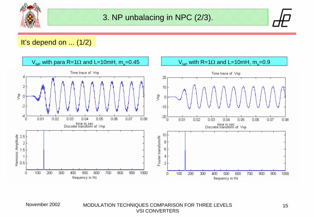
It’s depend on ... (1/2)
VNP with para R=1Ω and L=10mH, ma=0.45 VNP with R=1Ω and L=10mH, ma=0.9
3. NP 3. NP unbalacingunbalacing in NPC (2/3).in NPC (2/3).

November 2002 MODULATION TECHNIQUES COMPARISON FOR THREE LEVELS VSI CONVERTERS
16
VNP with R=10mΩ and L=10mH, ma=0.9
CONCLUSIONS:• VNP is a function of the amplitude modulation index.• VNP is a function of the load, that is to say, of the load power factor.
3. NP 3. NP unbalacingunbalacing in NPC (3/3).in NPC (3/3).
Same conditions, except C = 10mF
It’s depend on ... (2/2)

November 2002 MODULATION TECHNIQUES COMPARISON FOR THREE LEVELS VSI CONVERTERS
17
NPC Inverter.- Regenerative circuit
UDC L
Lua(t)
CDC ub(t)
uc(t)
eb(t)
ec(t)
Lea(t)
NPC VSI
FILTER GRID
4. 4. Simulation results (1/3)Simulation results (1/3)
Vab
Ia
• Load: R = 0.1Ω y L = 0.01mH• Phase = 5º
• UDC = 750V
• SVM with zero-sequence.
α
º5=δua
ea
ia

November 2002 MODULATION TECHNIQUES COMPARISON FOR THREE LEVELS VSI CONVERTERS
18
4. 4. Simulation results (1/3)Simulation results (1/3)
NPC Rectifier.- Controlled rectifier (active filter)
L
L
Lua(t)
CDCeb(t)
ec(t)
ub(t)
uc(t)
ea(t)
LOAD UDC
NPC VSI
iaea
ua
• Load: R = 0.1Ω y L = 0.01mH
• Phase = 5º
• SVM with zero-sequence.
º5=δ ua
eaia

November 2002 MODULATION TECHNIQUES COMPARISON FOR THREE LEVELS VSI CONVERTERS
19
4. 4. Simulation results (3/3)Simulation results (3/3)
NPC double converter
L
L
L ua(t)
CDCub(t)
uc(t)
ea(t)eb(t)
ec(t)UDC
Inverter 1.- RECTIFIERL R
Inverter 2.- INVERTER
• Load: R = 0.1Ω y L = 0.01mH
• Grid : R = 0.1Ω y L = 0.01mH

November 2002 MODULATION TECHNIQUES COMPARISON FOR THREE LEVELS VSI CONVERTERS
20
Modulation tecniques comparison
• Loads with a low power factor generate high ripple currents in NP.• Cosinusoidal modulation functions: Modify the offset of the reference signals.• Vectorial modulation functions: Choose of other redundant vectors.
Cosinusoidal Vectorial Cosinusoidalwith zero-seq.
Maximum ma 0.79 0.91 0.92
VNP variation δ Conmutation sequence δ
Implementation Easy Difficult Easy
NP unbalancing
5. 5. ConclusionsConclusions
Copyright © 2022 FDOKUMEN