Mission Concept for the Single Aperture Far-Infrared (SAFIR) Observatory
36
MISSION CONCEPT FOR THE SINGLE APERTURE FAR-INFRARED (SAFIR) OBSERVATORY DOMINIC J. BENFORD 1 , MICHAEL J. AMATO 2 , JOHN C. MATHER 1 S. HARVEY MOSELEY JR 1 and DAVID T. LEISAWITZ 1 Infrared Astrophysics Branch, NASA-Goddard Space Flight Center, Greenbelt, MD, U.S.A.; E-mail: [email protected] 2 Instrument Systems Branch, NASA-Goddard Space Flight Center, Greenbelt, MD, U.S.A. (Received 26 January 2004; accepted 31 March 2004) Abstract. The Single Aperture Far-InfraRed (SAFIR) Observatory’s science goals are driven by the fact that the earliest stages of almost all phenomena in the universe are shrouded in absorption by and emission from cool dust and gas that emits strongly in the far-infrared (40 µm–200 µm) and submillimeter (200 µm–1 mm). In the very early universe, the warm gas of newly collapsing, unenriched galaxies will be revealed by molecular hydrogen emission lines at these long wavelengths. High redshift quasars are found to have substantial reservoirs of cool gas and dust, indicative of substantial metal enrichment early in the history of the universe. As a result, even early stages of galaxy formation will show powerful far-infrared emission. The combination of strong dust emission and large redshift (1 < z < 7) of these galaxies means that they can only be studied in the far-infrared and submillimeter. For nearby galaxies, many of the most active galaxies in the universe appear to be those whose gaseous disks are interacting in violent collisions. The details of these galaxies, including the effect of the central black holes that probably exist in most of them, are obscured to shorter wavelength optical and ultraviolet observatories by the large amounts of dust in their interstellar media. Within our own galaxy, the earliest stages of star formation, when gas and dust clouds are collapsing and the beginnings of a central star are taking shape, can only be observed in the far-infrared and submillimeter. The cold dust that ultimately forms the planetary systems, as well as the cool “debris” dust clouds that indicate the likelihood of planetary sized bodies around more developed stars, can only be observed at wavelengths longward of 20 µm. Over the past several years, there has been an increasing recognition of the critical importance of the far-infrared to submillimeter spectral region to addressing fundamental astrophysical problems, ranging from cosmological questions to understanding how our own Solar System came into being. The development of large, far-infrared telescopes in space has become more feasible with the combination of developments for the James Webb Space Telescope (JWST) of enabling breakthroughs in detector technology. We have developed a preliminary but comprehensive mission concept for SAFIR, as a 10m-class far-infrared and submillimeter observatory that would begin development later in this decade to meet the needs outlined above. Its operating temperature (≤4 K) and instrument complement would be optimized to reach the natural sky confusion limit in the far-infrared with diffraction-limited per- formance down to at least the atmospheric cutoff, λ 40 µm . This would provide a point source sensitivity improvement of several orders of magnitude over that of the Spitzer Space Telescope (pre- viously SIRTF) or the Herschel Space Observatory. Additionally, it would have an angular resolution 12 times finer than that of Spitzer and three times finer than Herschel. This sensitivity and angular res- olution are necessary to perform imaging and spectroscopic studies of individual galaxies in the early universe. We have considered many aspects of the SAFIR mission, including the telescope technol- ogy (optical design, materials, and packaging), detector needs and technologies, cooling method and required technology developments, attitude and pointing, power systems, launch vehicle, and mission Astrophysics and Space Science 294: 177–212, 2004. C 2004 Kluwer Academic Publishers. Printed in the Netherlands.
-
Upload
independent -
Category
Documents
-
view
0 -
download
0
Transcript of Mission Concept for the Single Aperture Far-Infrared (SAFIR) Observatory

MISSION CONCEPT FOR THE SINGLE APERTURE FAR-INFRARED(SAFIR) OBSERVATORY
DOMINIC J. BENFORD1, MICHAEL J. AMATO2, JOHN C. MATHER1
S. HARVEY MOSELEY JR1 and DAVID T. LEISAWITZ1Infrared Astrophysics Branch, NASA-Goddard Space Flight Center, Greenbelt, MD, U.S.A.;
E-mail: [email protected] Systems Branch, NASA-Goddard Space Flight Center, Greenbelt, MD, U.S.A.
(Received 26 January 2004; accepted 31 March 2004)
Abstract. The Single Aperture Far-InfraRed (SAFIR) Observatory’s science goals are driven bythe fact that the earliest stages of almost all phenomena in the universe are shrouded in absorptionby and emission from cool dust and gas that emits strongly in the far-infrared (40 µm–200 µm)and submillimeter (200 µm–1 mm). In the very early universe, the warm gas of newly collapsing,unenriched galaxies will be revealed by molecular hydrogen emission lines at these long wavelengths.High redshift quasars are found to have substantial reservoirs of cool gas and dust, indicative ofsubstantial metal enrichment early in the history of the universe. As a result, even early stages ofgalaxy formation will show powerful far-infrared emission. The combination of strong dust emissionand large redshift (1 < z < 7) of these galaxies means that they can only be studied in the far-infraredand submillimeter. For nearby galaxies, many of the most active galaxies in the universe appearto be those whose gaseous disks are interacting in violent collisions. The details of these galaxies,including the effect of the central black holes that probably exist in most of them, are obscuredto shorter wavelength optical and ultraviolet observatories by the large amounts of dust in theirinterstellar media. Within our own galaxy, the earliest stages of star formation, when gas and dustclouds are collapsing and the beginnings of a central star are taking shape, can only be observed inthe far-infrared and submillimeter. The cold dust that ultimately forms the planetary systems, as wellas the cool “debris” dust clouds that indicate the likelihood of planetary sized bodies around moredeveloped stars, can only be observed at wavelengths longward of 20 µm.
Over the past several years, there has been an increasing recognition of the critical importance ofthe far-infrared to submillimeter spectral region to addressing fundamental astrophysical problems,ranging from cosmological questions to understanding how our own Solar System came into being. Thedevelopment of large, far-infrared telescopes in space has become more feasible with the combinationof developments for the James Webb Space Telescope (JWST) of enabling breakthroughs in detectortechnology.
We have developed a preliminary but comprehensive mission concept for SAFIR, as a 10 m-classfar-infrared and submillimeter observatory that would begin development later in this decade to meetthe needs outlined above. Its operating temperature (≤4 K) and instrument complement would beoptimized to reach the natural sky confusion limit in the far-infrared with diffraction-limited per-formance down to at least the atmospheric cutoff, λ � 40 µm . This would provide a point sourcesensitivity improvement of several orders of magnitude over that of the Spitzer Space Telescope (pre-viously SIRTF) or the Herschel Space Observatory. Additionally, it would have an angular resolution12 times finer than that of Spitzer and three times finer than Herschel. This sensitivity and angular res-olution are necessary to perform imaging and spectroscopic studies of individual galaxies in the earlyuniverse. We have considered many aspects of the SAFIR mission, including the telescope technol-ogy (optical design, materials, and packaging), detector needs and technologies, cooling method andrequired technology developments, attitude and pointing, power systems, launch vehicle, and mission
Astrophysics and Space Science 294: 177–212, 2004.C© 2004 Kluwer Academic Publishers. Printed in the Netherlands.
178 D.J. BENFORD ET AL.
operations. The most challenging requirements for this mission are operating temperature and aperturesize of the telescope, and the development of detector arrays. SAFIR can take advantage of much ofthe technology under development for JWST, but with much less stringent requirements on opticalaccuracy.
Keywords: far-infrared, submillimeter, telescope, SAFIR
1. Introduction
The Single Aperture Far-InfraRed (SAFIR) Observatory has been recommendedby consensus of the broad astronomical community in the National Academy ofSciences Astronomy Decadal Report (NAS Decade Report, 2001) as a high pri-ority scientific and technical successor to JWST and Spitzer (previously SIRTF).Additionally, the far-infrared community issued a more specific recommendation(Far-IR/SubMM Community Plan, 2003)
The first step [of a unified plan to implement the Decadal Report’s vision]is to develop the technology and start the planning for a cooled JWST classfar-IR observatory called SAFIR (Single Aperture Far-IR telescope), to beoperated like HST for a wide user community with a launch by the middle ofthe JWST lifetime in 2015.
This recommendation recognizes the exciting science opportunities offered bythe promise of a dramatic increase in sensitivity and angular resolution of a facilitylike SAFIR in the far-infrared spectral region. SAFIR “will enable the study ofgalaxy formation and the earliest stage of star formation by revealing regions tooenshrouded by dust to be studied by JWST, and too warm to be studied effectivelywith ALMA” (NAS Decade Report, 2001). In this paper, we present a missionconcept for SAFIR as envisioned in a 10 m-class far-infrared observatory that wouldbegin full-scale development late in this decade, for launch in ∼2015. For simplicity,we shall use the term far-infrared to denote the entire SAFIR wavelength range(20 µm–1 mm, Section 3) unless otherwise noted.
Advances in sensitivity and angular resolution in the far-infrared have laggedrelative to the optical, near-infrared, and radio portions of the spectrum for two mainreasons: the need to be above most or all of the Earth’s atmosphere because of verystrong absorption features of water vapor, and the need for very low temperaturetelescopes and instruments to reach the natural background limits of sensitivity atthese wavelengths. In addition, large apertures are required to achieve the angularresolution needed for comparison with modest optical and near-infrared studies,and coherent interferometry (as is used in the radio to achieve high angular res-olution without large single apertures) becomes increasingly challenging at highfrequencies. As a result of efforts on other large space telescopes, strategies arenow in hand to address effectively the simultaneous needs of a low temperature anda large single aperture.

MISSION CONCEPT FOR SAFIR OBSERVATORY 179
The current decade will see the launch of three new observatory-class far-infraredfacilities: Spitzer, SOFIA (the Stratospheric Observatory for Infrared Astronomy),and Herschel, each of which will provide substantial improvements in sensitivityand/or angular resolution as compared to facilities of the past such as the KuiperAirborne Observatory (KAO), the InfraRed Astronomy Satellite (IRAS), the Cos-mic Background Explorer (COBE), and the Infrared Space Observatory (ISO).Each of the present missions, however, is also clearly far from the current state-of-the-art in aperture and sensitivity for different reasons. Spitzer, a liquid heliumcooled telescope launched in August 2003, will easily reach the confusion limiton the sky in the far-infrared, but because of its modest 85 cm aperture, this con-fusion limit is substantially above that of the other two facilities. SOFIA, whichwill begin science operations in 2005, will have three times the aperture diame-ter of Spitzer, but because it will operate at ambient stratospheric temperatures,it will never approach the sensitivity of cryogenic space observatories. Late in thedecade the Herschel Space Observatory will provide improvements in both aperture(3.5 m) and operating temperature (T ≈ 80 K). At the long end of the far-infraredspectrum, λ � 100 µm, Herschel will reach a much lower confusion limit on thesky than Spitzer or SOFIA, but with integration times of order a few hours andfocal plane arrays of a few ×102–103 pixels. Herschel too is handicapped becauseits operating temperature is still so much greater than the equivalent brightnesstemperature of the natural sky background at these wavelengths. While Spitzer willprobe the faintest and most distant sources in the universe, SOFIA and Herschelwill view the brighter sources with higher spatial and spectral resolution. Even be-fore these new infrared observatories produce their stunning discoveries, it is clearthat their scientific and technical trajectory points directly at the need of a capable,far-infrared optimized observatory like SAFIR.
SAFIR will use state-of-the-art technology in lightweight optics, cryogeniccooling, deployable structures, and the most recent detector technology to en-able enormous sensitivity improvements over these previous missions, togetherwith much needed improvement in angular resolution. For example, the mappingspeed—which is proportional to pixels/sensitivity2—will be 106 times faster withtwo orders of magnitude more detectors and a two order of magnitude improve-ment in sensitivity. We touch on the compelling science drivers for this mission inthe following section. Following that, we then discuss the drivers on telescope anddetector specifications that result from the science requirements and our confidencein their achievability. We outline the concepts for the telescope design and discussthe ultimate sensitivity achievable by our approach. Following that, we present themission design in detail. Finally, we briefly describe the current status of the project.
2. Science Drivers
We shall not provide a complete scientific justification for the SAFIR mission here,as it has been treated in other publications (Harvey et al., 2003; Rieke et al., 2003).

180 D.J. BENFORD ET AL.
However, a few words of introduction are suitable, as the explicit mission require-ments (Amato et al., 2003) were derived from the scientific questions outlinedbelow.
2.1. OVERVIEW—THE ROL E OF TH E FA R IR/SUBMM
Regardless of the original emission process, cosmic energy sources glow in thefar-infrared and submillimeter. The broadband emission is due to the incredible ef-ficiency of interstellar dust in absorbing visible and ultraviolet photons and reemit-ting their energy as thermal continuum emission. The appearance of the earlyUniverse—of active galactic nuclei (AGN) and starbursting galaxies—and of starforming regions is transformed through this suppression of the visible and ultravi-olet and corresponding augmentation of the far-infrared and submillimeter. At thesame time, line emission in the far-infrared and submillimeter traces a variety ofstates of gas, from the heated cores of distant quasars to nearby cold protostellarclouds to our own Solar System’s planetary atmospheres. Low-lying far-infraredfine structure lines are the major coolants for interstellar gas. Molecular transitionsin this spectral range carry the signature of conditions in warm and dense inter-stellar clouds where stars and their solar systems form. Thus, we must look in thefar-infrared and submillimeter for clues to the underlying processes shaping theorigin, structure, and evolution of our Universe. We need large cold telescopes toreveal faint distant sources near the edge of the observable universe, and to show usthe details of warm sources, even nearby, with clarity that matches our capabilitiesfor seeing hotter material.
2 .2 . DISCOVERY OF NEW PHENOMENA
Technological advances enable astronomical discoveries. Harwit (1981) tried toquantify this relation in “Cosmic Discovery.” In the 25 years preceding publicationof the book, important discoveries were made in the first 5 years of the developmentof new technology that made them possible. The exceptional discovery potential inthe far-infrared to submillimeter region arises because the sensors are still substan-tially short of fundamental performance limits for the natural sky background fromspace, and the telescopes available to date have been very modest in aperture (lessthan 1 m). The previous Decadal Report (The Decade of Discovery in Astronomyand Astrophysics, 1991) made use of a parameter, which they called “astronomicalcapability,” to describe the discovery potential of new missions. This parameter isproportional to the time required to obtain a given number of image elements toa given sensitivity limit. SAFIR will have astronomical capability exceeding thatof past far-infrared facilities by a factor of about 1010, and will still offer a gain ofabout 105 after Spitzer and Herschel have flown. A gain of this magnitude is similarto the gain from the initial use of the Hooker 100-Inch Telescope on Mt. Wilsonto the Hubble Space Telescope. The capabilities of SAFIR will enable enormous

MISSION CONCEPT FOR SAFIR OBSERVATORY 181
TABLE I
Telescope requirements for SAFIR
Parameter Requirement Science targets
Aperture >8m High z galaxies; Debris Disks
Temperature ∼ 4 K L∗ Galaxy at z ∼ 5; zodi limit
Wavelength range 20–800 µm JWST overlap; Gas cooling lines
Diffraction limit ≥40 µm (1′′) Debris disks, distant galaxies
Pointing accuracy ∼ 0.5 − 1.0′′ Driven by 40 µm Diffraction limit
Pointing stability ∼ 0.1′′ Driven by 40 µm Diffraction limit
Lifetime >5 Years Productivity
progress on some of the most important current problems in astronomy, and thishuge gain in capability is certain to lead in new and exciting directions as well.
3. Telescope and Instrument Requirements
Table I summarizes the top level requirements on the SAFIR telescope and thescience observations driving each of them.
The two most critical requirements are aperture and operating temperature, as-suming the emissivity is minimized to a level limited by optical coatings and reason-able stray light considerations. The aperture and telescope background emissiondetermine its ultimate limiting sensitivity (see Section 5) as well as the practi-cal limit of the number of seconds of integration required to reach the confusionlimit on the sky. The science drivers for SAFIR require the confusion noise to below enough to observe typical dusty L∗ galaxy formation close to the epoch ofmetal enrichment, z > 5. Another important driver is the ability to study the for-mation and evolution of planetary systems via their debris disks out to modest dis-tances, D ∼ 100 pc. These requirements imply an aperture of order 10 m for SAFIR.Figure 1 shows an estimate of the confusion limit for broadband observations witha 10 m aperture telescope (Blain et al., 1998) as a function of wavelength relativeto the photon background limited sensitivity for an assumed 5% emissive telescopeof various possible temperatures and for two representative integration times, 1 and104 s. To reach a sensitivity and confusion limit somewhat less than the brightnessof L∗ galaxies at z ∼ 5 at 100 µm (∼4 µJy) requires T ≤ 10 K. For spectroscopicpurposes, however, the confusion limit is much lower and it is therefore importantthat the telescope be even colder, 4 K, to detect lines from distant galaxies.
The next most critical requirement is on the short wavelength limit for SAFIR,because this drives the optical surface and alignment tolerances and thus thetechnology chosen for the primary mirror. In order to provide high sensitivityand angular resolution for complete coverage of the very wide range of wave-lengths in the infrared, SAFIR’s wavelength coverage would extend down to over-lap with JWST’s at λ ∼ 20 µm. The science drivers described above require

182 D.J. BENFORD ET AL.
Figure 1. SAFIR sensitivity as a function of telescope temperature and integration time, as comparedto the confusion limit.
diffraction-limited performance at a somewhat more relaxed wavelength limit of40 µm for imaging of debris disks and distant galaxies. The diffraction limit at40 µm for a 10 m telescope is ≈1′′ (1.22 λ/D). Therefore, the requirements onpointing accuracy and stability (∼0.5 − 1′′ and 0.1′′, respectively), as well as sur-face quality for SAFIR will be relatively modest in comparison with JWST. Thusthe JWST engineering research and development can be assumed to carry over inpart to SAFIR. In the post-JWST era, the biggest technological challenge is likelyto be the lower required telescope temperature.
The science program that motivates the need for SAFIR requires a complement ofimaging and spectroscopic instruments over the entire wavelength range of SAFIRfrom 20–800 µm. Table II lists a strawman complement of instruments, noting thespectral resolution (R ≡ λ/�λ) and the field of view, along with some of thescience drivers from Section 2.
The strawman camera uses a dichroic and a double filter wheel to providesimultaneous diffraction-limited imaging in two bands, one in the 20–100 µm rangewith 1′ field-of-view, the other from 140–600 µm with 4′ field-of-view. For the lowresolution spectrometer, a small field image slicing spectrometer is well matchedto the size of many of the objects being studied, and provides instantaneous full-wavelength coverage by using a pair of broadband gratings. For the moderateresolution R ∼ 2000 spectrometer, a long slit grating spectrometer is necessary,although at the shorter wavelengths this could be achieved with an image slicingspectrometer similar in design to FIFI-LS on SOFIA (Looney et al., 2003). Givencurrent and near-future technology developments, the high resolution spectrometerwill likely be a single-moded coherent receiver. For this instrument, the developmentof extremely broad frequency range detectors (such as hot electron bolometers) andlocal oscillators.

MISSION CONCEPT FOR SAFIR OBSERVATORY 183
TABLE II
Strawman instrument complement for SAFIR
Wavelength rangeInstrument Driving science Spectral resolution FOV
Camera 20–600 µm ∼5 1–4′
High z Reddenning; searches for KBOs;
imaging surveys. . .
Spectrometer 20–100 µm ∼100 ∼10′′ (Image
slicing)
(low resolution) Ice features in Debris Disks, YSOs, etc.
Spectrometer 20–800 µm ∼2000 (150 km/s) ∼1′
(moderate resolution) Cooling lines (e.g., C+, N+);
Chemical evolution
Spectrometer 25–520 µm ∼106 (0.3 km/s) >1 beam
(high resolution) Dynamics of star forming regions,
evolved stars; Gas Cooling
Figure 2 displays the sensitivity of SAFIR relative to a number of precursormissions as well as several that are hoped to follow it. Also shown in Figure 3 is theangular resolution of SAFIR as a function of wavelength in the context of existing,planned, and possible future missions. It is clear from these figures that SAFIR notonly offers a dramatic increase in sensitivity over precursor missions, but providesa bridge in sensitivity between what will be the most powerful telescope at shorterwavelengths (JWST), and that at longer wavelengths (ALMA).
4. Telescope Concepts and Expected Performance
SAFIR has been recommended by several assemblies (NAS Decade Report, 2001;Far-IR/SubMM Community Plan, 2003) during the past few years. They have madethese recommendations because information vital to the realization of NASA’smajor scientific objectives is uniquely available in the far-infrared. It is importantto recognize that SAFIR is the first and foremost mission to fulfill this scientificneed. Further study of SAFIR mission design concepts will be needed before asingle approach that accomplishes the highest priority science goals with readytechnology, subject to programmatic considerations, can be selected. Three possibleconcepts are shown below in Figure 4: (top) based on the original JWST, the “NGSTStrawman” design; (middle) derived from the current JWST for maximum heritageand fidelity; (bottom) based on a sparse aperture telescope to improve angularresolution. The sparse aperture concept has the equivalent collecting area of thetwo more compact telescopes, and is 17 m tip-to-tip.

184 D.J. BENFORD ET AL.
Figure 2. SAFIR sensitivity compared to present and future mission concepts.
The SAFIR mission shown at the top in Figure 4, and detailed in Figure 5,is a mission concept that has been studied in detail at NASA’s Goddard SpaceFlight Center. It is based on the National Academy’s recommendation: “To takethe next step in exploring [the far-infrared], the committee recommends the SAFIRObservatory, a. . . telescope that builds on the technology developed for JWST.”(NAS Decade Report, 2001).
Taking the contemporary (2002) JWST design as a starting point, a detailedanalysis was made of the changes necessary to produce a SAFIR that is implementedas a larger, colder version of JWST (Amato et al., 2003). A broad list of scienceinvestigations was used to generate an explicit list of technology requirements, fromwhich the observatory requirements (Section 3) are derived. After the selection ofthe JWST prime contractor, a second design more directly emulating the chosenJWST architecture was developed (Figure 4, middle); a further design with a sparseaperture telescope was adapted from this architecture (Figure 4, bottom).
One of the immediate differences between SAFIR and JWST is that in order toachieve the ultimate sensitivity for the difficult spectroscopic observations plannedfor SAFIR, the telescope and other optics will have to be cooled to 4 K, well belowthe ∼35 K achieved by JWST’s passively cooled architecture. GSFC’s conceptualdesign for SAFIR uses cascaded cryocoolers to provide moderate cooling powersat 40 K, 15 K, and 4 K. The JWST-like sunshade is mounted on the 40 K stage,whereas a single additional layer of the sunshade is mounted on the 15 K stage.

MISSION CONCEPT FOR SAFIR OBSERVATORY 185
Figure 3. SAFIR angular resolution compared to present and future mission concepts.
This sunshade provides an environment so well shielded from the Sun that onlymodest cooling is needed to cool the telescope to 4 K.
For JWST, there were two methods developed for deploying a large, rigid pri-mary mirror: petal-like folding or drop-leaf-table-like folding. The GSFC SAFIRdesign baseline is to reproduce JWST’s approach, using a table folding. OtherSAFIR options—particularly for a sparse aperture (Figure 4, bottom)—would usea petal fold. Since SAFIR is larger than JWST, the designs will diverge somewhat:a petal design will result in small notches around the outside of the aperture, whilea table-fold design may have two small slices off the aperture edges. The PSFwill be slightly degraded, but the collecting area at large radii will still benefitconfusion-limited and sensitivity-limited observations. The choice of optical sur-face is largely independent of the method of deployment and can be deferred untilJWST has validated its technology. JWST has selected a C/SiC mirror surface witha composite carbon fiber structure. Among the other materials under considerationfor SAFIR are carbon fiber mirrors and structure (possibly with glass face-sheets),C/SiC mirrors and structure, beryllium, and aluminum mirrors. Given that SAFIRdoes not require diffraction-limited performance at λ < 40 µm, it might be possibleto duplicate the JWST mirror technology, but without the final polishing process.It is also possible that the telescope could use a non-JWST-like optical design, asdiscussed below.
To fit the four instruments outlined in Table II, a large field of view (∼15′ diame-ter) is needed. Because the diffraction-limited resolution at the shortest wavelengthsis 1′′, a pointing stability of 0.1′′ is desirable. This can be achieved only with acryogenic pointing camera located on the instrument package. Our concept uses a

186 D.J. BENFORD ET AL.
Figure 4. A set of possible SAFIR mission concepts developed at NASA/GSFC. From top to bottom,these are the “NGST Strawman” design, the “JWST Heritage” design, and the “Sparse Aperture”design.
Figure 5. SAFIR concept developed at NASA/GSFC, based on JWST heritage.
2 µm focal plane camera with a large field of view and high speed subarray readoutto measure jitter offsets from known 2MASS point sources.
There is work underway to develop a new architecture to break the paradigmof launching large, often massive mirrors into space. NASA has been developinga concept using membrane mirrors tensioned by truss structures assembled by

MISSION CONCEPT FOR SAFIR OBSERVATORY 187
Figure 6. DART concept.
astronauts. Called the Dual Anamorphic Reflector Telescope (DART; Dragovan,2002), this telescope consists of two convex parabolic cylindrical reflectors orientedwith respect to each other to produce a point focus (Figure 6). Since each reflectorcontains only a single simple curve, the mirrors can be formed by tensioning areflective foil over a frame with a parabolic contour along one axis. The use of anextremely low-mass membrane for the reflective surfaces would significantly reducethe mass of the telescope support. The DART architecture uses a thin membranefor its reflectors, so the density of the mirror surface is independent of size. Infact, the ratio of structure to reflector mass can decrease with increasing aperturesize. The approach has significant implementation issues for use in SAFIR; forinstance, it may be most effectively assembled by astronauts in orbit, and the large,sparse membranes and structure may be more difficult to cool to 4 K than a morecompact conventional mirror technology. If the problems of deploying and coolinga membrane mirror can be solved, and the field of view and surface figure madeadequate, this technology might be a viable replacement for the JWST mirror in aSAFIR concept.
5. Ultimate Sensitivity of a Cryogenic Far-Infrared Telescope
It is reasonable to assume that a future space-based far-infrared mission will likelyrequire that the system sensitivity be maximized for point source detection. Theideally sensitive instrument will be limited only by the photon statistics from thenatural backgrounds outside of Earth orbit. The natural sky background for a coldtelescope in space is extremely low as compared to the background from a warmtelescope or beneath the Earths atmosphere. To take advantage in this limit, instru-ment sensitivity can be increased by orders of magnitude.
The natural sky background limit is set by the combination of several components(Figure 7), and is particularly low in the 50–500 µm regime. In order to keep below

188 D.J. BENFORD ET AL.
Figure 7. Intensity of natural sky background in a diffraction limited beam of unity bandwidth; theregion from 50–500 µm is particularly dark.
Figure 8. The total sky background compared with the emission of telescopes of 5% emissivity.
this intensity limit, the telescope must be cold: 4 K to be equal to the sky background(Figure 8). An optimally sensitive telescope for operation in the far-infrared suchas SAFIR must be this cold.
Of course, there are other limits to ultimate sensitivity besides the photon noiselimit presented above. In the case of broadband observations in the far-infrared,

MISSION CONCEPT FOR SAFIR OBSERVATORY 189
Figure 9. Sensitivity limits of a cryogenic space observatory, showing the balance between photonnoise (collecting area) limited and confusion (diameter) limited observations.
the confusion limit is significant. The MIPS instrument on Spitzer is expected tobe confusion limited (one source detected at the 1σ limit per beam) at 160 µm inonly seconds of integration. The confusion limit drops as a very fast function ofthe mirror diameter, due to the increased resolving power. The tradeoff wavelengthbetween photon-limited (where collecting area is important) and confusion-limited(where diameter is important) sensitivity is a function of the diameter, and can beextrapolated to future space telescopes. Using the photon noise calculated abovewith the confusion limit calculated by Blain et al. (1998) we find that this wave-length falls between 30 µm for a 1-m-class telescope and 80 µm for a SAFIR-sizedobservatory (Figure 9).
In the case of narrower bandwidth observations, the situation changes: the con-fusion limit to sensitivity is noticeably reduced. As a simple approximation, wecalculate the sensitivity of SAFIR with a spectral resolution of R = λ/�λ = 1000,and assuming no confusion. In Figure 10 (Left), we compare this sensitivity withdifferent telescope temperatures. We then calculate the worst case ratio of sen-sitivity degradation at a given temperature. This resultant sensitivity loss can beconsidered as an effective aperture loss. This is plotted in Figure 10 (Right), forcases with confusion (R = 5) and without confusion (R = 1000). In reality, theconfusion limit at R = 1000 is not zero, but around a factor of ∼100 below the limitat R = 5. This level of confusion is sufficiently low and so it does not significantlylimit the sensitivity until integration times of order 105 s are considered.

190 D.J. BENFORD ET AL.
Figure 10. (Top) Sensitivity of SAFIR at a variety of telescope temperatures, assuming 1% emissivityand a spectral resolution of λ/Dλ = 1000 (300 km/s). (Bottom) Degradation in effective aperture astelescope temperature increases, for 1% emissivity and the cases of a spectral resolution of λ/Dλ = 5with confusion and for λ/Dλ = 1000 with low confusion.

MISSION CONCEPT FOR SAFIR OBSERVATORY 191
6. SAFIR Mission Design
The National Academy has recommended that a SAFIR design draw on JWSTtechnology (NAS Decade Report, 2001). Because this is the first published SAFIRmission design, building on JWST provides the highest fidelity design on the short-est timescale, and is a suitable point of departure for other designs. A 10-m diameter,4 K telescope with a far-infrared instrument suite of three spectrometers and a broad-band camera is challenging. To mitigate this challenge, we consider what of theJWST design and technologies might be reused for the SAFIR observatory. This is anecessary exercise to pursue to show the feasibility of SAFIR and to lend credibilityto the design, with its estimated parameters, cost, and schedule. We have developeda SAFIR conceptual design that is heavily based on many JWST designs. We thinkthis approach makes sense because JWST will spend a great deal of time and moneymaking its design and technologies work several years in advance of SAFIR. It isexpected that this approach has the potential to reduce SAFIR development timeand costs significantly.
Because our current baseline SAFIR concept is an JWST-like concept, we mustconsider needed technologies and technology development with an eye on whatJWST will already need to have completed prior to its launch. In this section,we present a description of the SAFIR conceptual design (shown in Figure 11),highlighting needed technologies, their development status today and the neededstatus prior to JWST launch. Several technologies—most notably the detectors andcryocoolers—will require developments specific to SAFIR and future far-infraredmissions.
Figure 11. SAFIR concept based on JWST; developed by NASA/GSFC.

192 D.J. BENFORD ET AL.
6.1. TELESCOPE DESIGN
The telescope is the most fundamental part of a large observatory. If the premise ofan initial SAFIR concept is to take advantage of any designs and technologies ofJWST that make sense for SAFIR, then the SAFIR architecture should use a hingedfolding primary mirror. However, SAFIR requires twice the collecting area of JWST,and so a petal-folding primary mirror may be the only suitable approach, even ifit does not draw on JWST heritage. However, the concepts are not substantiallydifferent for our purposes and both can be used as a basis for a SAFIR mission.
The three major SAFIR requirements that differ from JWST parameters are thesize of the primary mirror, the colder temperature, and the longer wavelength rangeof operation. With the exception of the caveat mentioned above, both proposedJWST approaches can be used to deploy a larger telescope. The basic SAFIRconcept uses designs not greatly different from current JWST concepts to deploythe larger SAFIR telescope.
6.2. TELESCOPE TECHNOLOGIES
The telescope requires development in three distinct technology areas to realizea lightweight, cryogenic 10 m observatory. For its purposes, most of these willbe addressed by JWST developments. First, the method of folding and deployingthe primary mirror will require careful mechanical design and substantial groundtesting. SAFIR should use the same approach as JWST, but with a larger primarymirror diameter. If the mirror is segmented into leaves—the baseline approach—itwill be constrained to a maximum size of around 9 m, but with a completely filledaperture. If the mirror is segmented into petals, a 10-m diameter mirror can bestowed into a launch vehicle fairing, but with notched regions around the outeredge.
The second technology involved is the method of phasing and controlling themirror surface, which requires sensitive detection of position errors and precisionactuation of the segments. SAFIR’s longer wavelengths make this task roughly 10times less precise than that for JWST, and the lower temperature will reduce thermaldistortions that require JWST’s mirror to be rephased periodically. It is likely thatthe mirror will need to be phased only once and left for the mission duration, butthe actuators will probably still be needed as a contingency measure.
The third technology is the mirror surface material. Several options have beeninvestigated for JWST, including glass face-sheeted composites, C/SiC, and Beryl-lium. SAFIR may be able to use polished aluminum as well, if the figure can be madesmooth enough. JWST has chosen C/SiC, a technology that works well at ∼35 Kand is lightweight but stiff. SAFIR needs adequate thermal conductivity at 4 K,and would prefer lower areal density materials at the expense of some stiffness.The C/SiC approach will need to be investigated further for the SAFIR-specificimplementation.

MISSION CONCEPT FOR SAFIR OBSERVATORY 193
Figure 12. (Top) Optical layout of SAFIR telescope. (Bottom) focal plane arrangement of instruments.
Several optical designs for the telescope are possible, but we are using an JWST-like three mirror telescope as a baseline, shown at left in Figure 12. This design isslightly off-axis, but features a flat steering mirror that can be used for fine pointingcorrection (which may be needed, as mentioned in Section 6.8). The field of viewof this design is large, permitting ample space for the four instruments (Figure 12,Right) and a focal plane star sensor (not shown).
A point spread function (PSF) map has been produced for the two differentSAFIR designs. In Figure 13, the PSF of a circular SAFIR aperture is shown.In Figure 14, the PSF for the sparse aperture concept is shown. It is clear thatthe artifacts are more prominent for the sparse aperture version, but it also yieldsa narrower PSF (at λ = 40 µm, θ ∼ 0.6′′ as opposed to θ = 1.0′′) and hasseveral low sidelobe regions; practically, the two PSFs are indistinguishable at 4′′
radius.

194 D.J. BENFORD ET AL.
Figure 13. PSF of the circular aperture: (Left) log scale; (Right) linear scale.
Figure 14. PSF of the sparse aperture: (Left) log scale; (Right) linear scale.
6 .3 . INSTRUMENT DESIGN AND DETECTOR NEEDS
To cover the wide range of wavelengths and spectral resolutions, SAFIR may needfour instruments, summarized below:
– Instrument A; CAM: Broadband camera with spectral resolution of R∼5 cover-ing 20–600 µm, using simultaneous two-wavelength imaging with a 1′ field ofview (20–100 µm) and a 4′ field of view (140–600 µm). A filter wheel with 6positions will permit the selection of any band over the entire range.
– Instrument B; LRS: Low resolution spectrometer with spectral resolution of∼100 covering 25–100 µm, using two simultaneous integral field grating spec-trographs. The field of view will be about 6′′ on a side from 25–50 µm and 12′′
on a side from 50–100 µm.– Instrument C; MRS: Moderate resolution spectrometer with spectral resolution of
∼2000, covering 20–720 µm. At short wavelengths (20–120 µm), HRS featuresan integral field grating spectrometer with an 18′′ field of view, whereas at longerwavelengths (120–720 µm), it will use a long slit grating spectrometer with anadjustable slit up to 18′′ × 96′′ in size.
– Instrument D; HRS: High resolution spectrometer with spectral resolutionof ∼100 000 covering 25–520 µm. A heterodyne spectrometer is the mostlikely technology for this application, and would have a sparsely-sampled ar-ray of single-moded detectors with at least 2 × 2 format, each pixel being one

MISSION CONCEPT FOR SAFIR OBSERVATORY 195
diffraction-limited beamwidth. A beam steering mirror is used to fill in the gapsof the array.
It is unlikely that any JWST detector-related technology can be used for SAFIRwith the exception of a 2 µm camera for star tracking. To realize these instruments,the following technological investments need to be developed specifically to enableSAFIR:
– For CAM, large format arrays covering the 20–600 µm range are needed. Formatsof 1282 pixels, each with a noise equivalent power (NEP) of 3 × 10⁻¹⁹W/
√Hz
are required. Superconducting bolometer arrays can, with sufficient developmentfunding, meet these requirements.
– For MRS, large format arrays covering the 20–720 µm range are needed. Formatsof 642 pixels, each with a noise equivalent power (NEP) of 1 × 10⁻²⁰W/
√Hz
are required. It may be necessary to develop novel approach to detectors to meetthis sensitivity requirement.
– For LRS, similar large format arrays to MRS must be developed, but with lowersensitivity for higher photon background.
– For HRS, single-moded coherent detectors operating near the quantum limitover the 25–520 µm range (0.6–12 THz) are needed. To this end, increasing thetunable bandwidth of detectors and local oscillator sources is a key researchinvestigation to be undertaken. Hot electron bolometers are the most promisingcurrent technology for this purpose, if they can be manufactured with near-quantum noise. Additionally, backend spectrometers using low-power digitalautocorrelators should be developed.
6.4. DETECTOR TECHNOLOGIES
The far infrared and submillimeter ranges have benefited relatively little from in-vestments in detector technology for nonastronomical pursuits. In this regard, theydiffer dramatically from the visible, near- and mid-infrared, and radio regions.Detectors in those spectral regions closely approach theoretical performance lim-its. For example, in the visible, CCDs have quantum efficiencies greater than 90%,read noises of about two electrons, and formats up to many millions of pixels.In the far-infrared the investment in technology to date has been modest, due toboth technological hurdles in using the technology which have now largely beenovercome, and the lack of direct applications in defense and commercial industry.This much smaller prior investment has left the possibility for orders of magni-tude near-term progress toward fundamental limits. NASA missions are the onlymajor customers for this technology, and an augmented NASA investment will benecessary to enable SAFIR and other far-infrared and submillimeter missions, in-cluding Explorers. These investments will guarantee our nation’s leadership in thisimportant technology.

196 D.J. BENFORD ET AL.
Figure 15. State-of-the-art large format far-infrared detector arrays: (Left) Spitzer/MIPS (Young etal., 2003); (Right) SHARC II (Dowell et al., 2003).
SAFIR requires sensitive arrays containing thousands of detectors. Far-infraredphotoconductors are the most advanced in array construction, the best example ofwhich is the 32 × 32 element 70 µm Spitzer/MIPS array (Figure 15 at left; Younget al. (2003). However, they fall somewhat short of theoretical limits in potentialperformance and respond only up to the excitation energy (around λc = 200 µm).Development for SAFIR will require both larger arrays (128 × 128) and longerwavelengths (720 µm). Bolometers have broad spectral response and are themost advanced submillimeter continuum detectors, but they require extremely lowoperating temperatures. The largest existing bolometer array is the 12×32 array inthe SHARC II instrument at the Caltech Submillimeter Observatory (Figure 15 atright; Dowell et al., (2003)—and its JFET readout technology cannot presentlybe multiplexed to permit larger arrays. Development needs to emphasize im-proved array technology, such as SQUID-based multiplexing, and superconducting-thermometer bolometers that interface well to SQUID electronics. Hot electronbolometer (HEB) mixers provide the best heterodyne operation above the supercon-ducting gap frequency of NbTiN, at around 1200 GHz. Heterodyne detectors havelarge practical advantages for spectroscopy over photoconductors and bolometers.Development needs to address reducing noise temperatures and developing supportelectronics to allow large scale spatial arrays, and to push to higher frequencies andgreater tunable frequency ranges.
6.4.1. Detectors for Low Spectral ResolutionThe two lower spectral resolution instruments listed in Table III require very similardetectors. They differ slightly in the number of pixels, but more significantly in theirnoise equivalent power (NEP). We evaluate the detector requirements using theRichards figure of merit (Richards, 2003), the number of pixels divided by NEP2
(which is essentially the mapping speed). We find that the requirement for thebroadband camera is 1.6 × 1042 pixels/W2/s; for the low resolution spectrometer,it is 1 × 1043 pixels/W2/s. By way of comparison, the largest bolometer arrayin existence (SHARC II) has a figure of merit of about 4 × 1036 pixels/W2/s.(More sensitive detectors can be made, but the background for suborbital telescopes

MISSION CONCEPT FOR SAFIR OBSERVATORY 197
TABLE III
SAFIR observatory conceptual design mass estimates
is high enough that this is unnecessary.) Richards law states that, averaged overlong times, the figure of merit of the state-of-the-art bolometers doubles everyyear, so that about 20 years of development ought to be needed to achieve theleap to the SAFIR broadband detectors. However, the revolution represented bysuperconducting bolometers is poised to permit an improvement in the state-of-the-art in the form of the SOFIA/SAFIRE detector array, which, when completedin 2005, will have a figure of merit of 5×1040 pixels/W2/s. From this starting point,Richards law suggests that the SAFIR detectors will be feasible for flight by 2013.
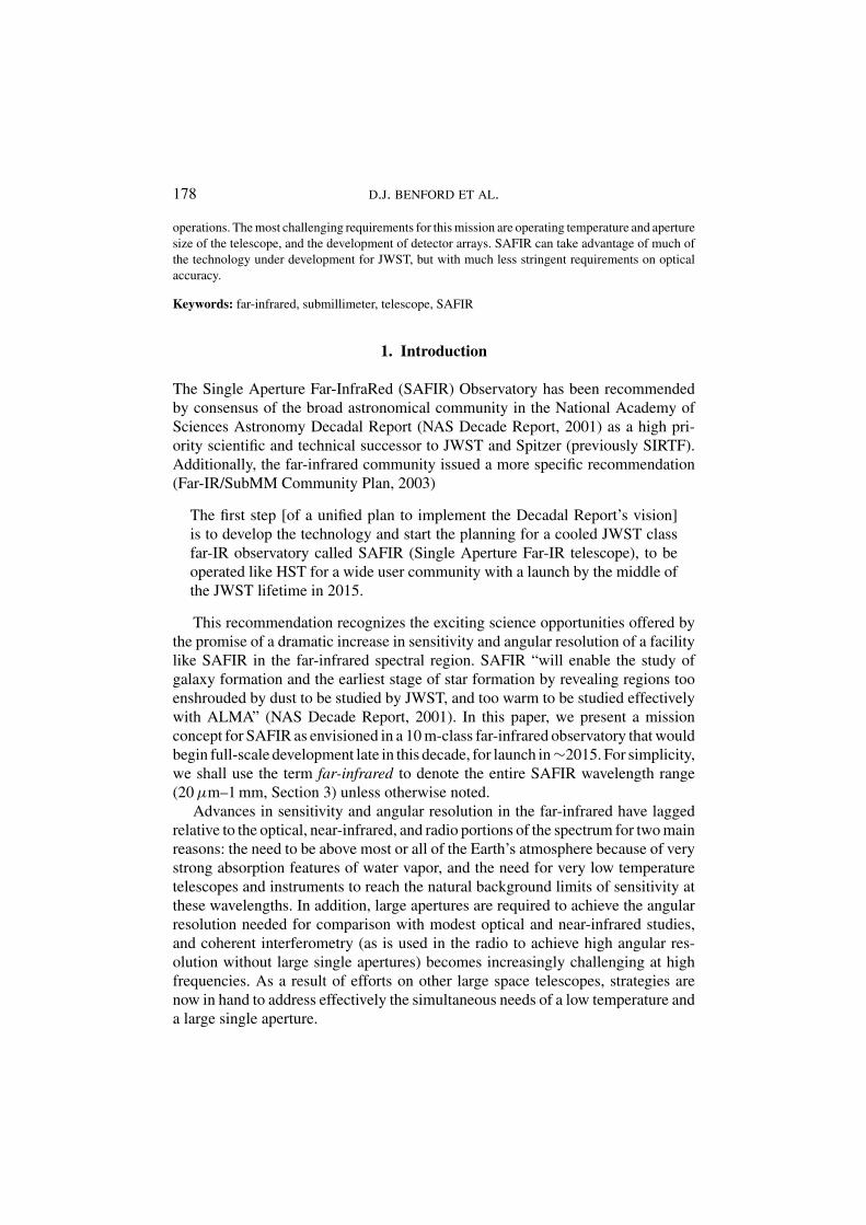
Using the background power calculation from Figure 7, we compute the powerabsorbed by a diffraction-limited detector on a 4 K, 10-m telescope. This power Pcan be converted into a photon-limited noise equivalent power at optical frequencyν using NEPphoton = √
2Phν and a photon-limited noise equivalent flux density(NEFD) assuming optical efficiency η using NEFD = 2NEP/(Aη�ν). The resultsare shown for a spectral resolution of λ/�λ = 5 and λ/�λ = 100 in Figure 16. Inthe core SAFIR observing bands of 30–300 µm, the optical power is surprisinglyflat, and the NEP values for the detector are 10−19 W/
√Hz at λ/�λ = 5 and
2 × 10⁻²⁰ W/√
Hz at λ/�λ = 100.
6.4.2. Detectors for High Spectral ResolutionIndependent of optical approach, a maximum-sensitivity spectrometer will be dis-persive. A large array of close-packed detectors is a useful thing in such a case, eitherto cover larger fields (e.g., for a Fabry-Perot) or more bandwidth (e.g., for a gratingspectrometer). These detectors will have to be extremely sensitive, with NEPs ofaround 3 × 10⁻²¹ W/
√Hz. This is shown graphically in Figure 17, where the same
calculations as discussed in Section 6.4.1 are applied for a resolving power of 2000(equivalent to a velocity resolution of 150 km/s, suitable for minimally resolvinglines in galaxies).
When building a high resolution spectrometer for a wavelength longward of∼300 µm (1 THz), it is common to use coherent spectrometers. If the instanta-neous bandwidth desired is higher than λ/�λ = 104 (30 km/s), the bandwidth
198 D.J. BENFORD ET AL.
Figure 16. (Top) Broadband detector sensitivity: optical power, photon noise equivalent power, andphoton-limited noise equivalent flux density for a camera with a spectral resolution of λ/�λ = 5.(Bottom) Optical power, photon noise equivalent power, and photon-limited noise equivalent fluxdensity for a low-resolution spectrometer with a spectral resolution of λ/�λ = 100.

MISSION CONCEPT FOR SAFIR OBSERVATORY 199
Figure 17. (Top) Detector sensitivity: optical power, photon noise equivalent power, and photon-limited noise equivalent flux density for a spectrometer with a spectral resolution of λ/�λ = 2000(150 km/s). (Bottom) NEFD for a λ/�λ = 104 spectrometer using photon-limited direct detectorscompared with quantum-limited coherent detectors. Predicted fluxes for redshifted fine-structure linesfrom galaxies are shown for reference.

200 D.J. BENFORD ET AL.
Figure 18. Flux density sensitivity at 1 km/s resolution from 300 GHz to 3 THz (100 µm–1 mm)of several facilities envisioned for the coming decade, as compared to the sensitivity of the SAFIRobservatory.
of the intermediate frequency amplifier and backend spectrometer need be only∼100 MHz, easily achievable by today’s standards. Given sufficient technologyinvestment, could a coherent spectrometer be developed to cover the SAFIR bands(20 µm–520 µm) to provide information via very high resolution observations? Forthe case of Galactic observations, where line strengths are relatively larger thoughline widths are narrow, this is possible: SAFIR’s detection limit in a 1 km/s linein 104 s is about 1 mK at 300 µm with a heterodyne spectrometer. However, indistant extragalactic sources where linewidths are larger but sources are fainter,it becomes harder for such an instrument due to the limitation of sensitivity fromquantum noise. Figure 17 (right) shows a comparison between the NEFD of a quan-tum limited coherent spectrometer and a high resolution dispersive direct detectionspectrometer, both with λ/�λ = 104. To put the comparison into scientific terms,the predicted fluxes of bright far-infrared fine-structure lines from starburst galaxiesas they are redshifted to submillimeter wavelengths are shown. The quantum limitwill make the detection of these lines at z > 1 a difficult proposition. In the quantumlimited case, a 270 K telescope is as good as a 4 K telescope, and so ALMA wouldbe more sensitive than SAFIR wherever they overlapped.
6.4.3. The Case for High Resolution SpectroscopyWe compare the predicted sensitivity of a heterodyne spectrometer on SAFIR tosimilar instruments of other facilities available in the next decade. In Figure 18, wehave made an estimate of the NEFD for an advanced instrument suite appropriate toa ground-based 10 m-class telescope (e.g., Kooi et al., 2002), a hypothetical ALMAsuite with receivers at all frequencies available from the ground, a hypothetical op-timized SOFIA heterodyne spectrometer covering the whole 300 GHz − 3 THzband, and the HIFI instrument on Herschel. NEFD is chosen rather than noise
MISSION CONCEPT FOR SAFIR OBSERVATORY 201
temperature, as the point source sensitivity of each facility is the more relevantparameter. As can be seen, SAFIR will provide a substantial gain in sensitivity atfrequencies above 1THz, enabling new science at these frequencies. Where ALMAis operational, its sensitivity and high angular resolution are superior, but the avail-ability of the >1 THz windows is not common. It is worth noting that all of thesefacilities are quantum-limited except where the atmospheric emission is strong.For this reason, a warmer but larger implementation of SAFIR would yield bettersensitivity for its heterodyne instrument. As mentioned previously, the mirror tech-nology shown in Figure 6 yields a very low areal density but more difficult coolingproblems. Thus, it might be more easily scaled to a larger (10–30 m), warmer(∼30 K) telescope than the baseline 10 m, 4 K SAFIR.
6.5. THERM AL DESIGN
JWST will use an all-passive design to achieve a telescope temperature of ∼35 K.This is a reasonable practical limit for a telescope relying on radiative coolingalone. Reaching the more challenging 4 K telescope and instrument temperaturesrequires better isolation from solar radiation and active cooling to get below the∼7 K ambient (nonsolar) background at L2.
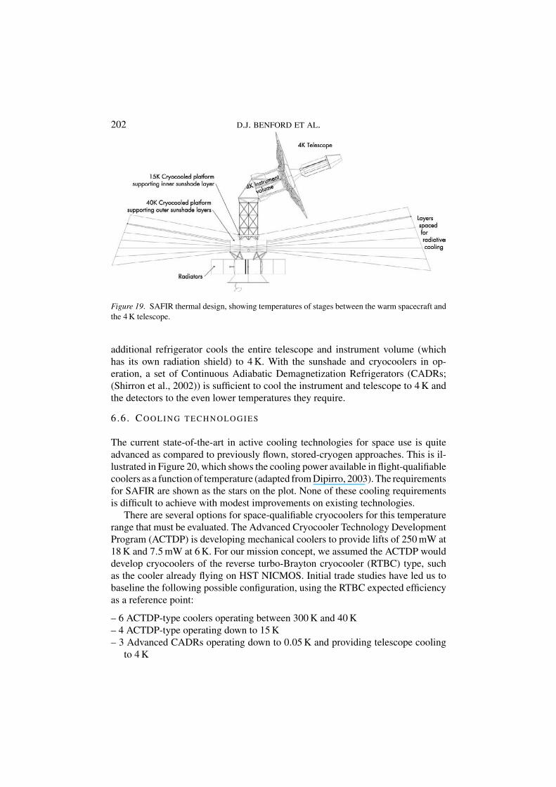
The dominant heat load on the SAFIR observatory is from the Sun; its lightmust be attenuated by ∼6 orders of magnitude to keep the telescope cold. JWSThas designed a sunshade to attenuate this light by ∼3.5 orders of magnitude, usingmultiple separated radiatively cooled reflective blankets. This sunshade is deployedfrom the warm spacecraft, and radiatively cools until the inner layer is at a tem-perature of ∼100 K in its warmest place. This “hot spot” is the dominant source ofstray light at mid-infrared wavelengths. For SAFIR, the equivalent “hot spot” mustbe 15 K or colder, which puts a much greater burden on the sunshade. To meet thisrequirement, we have mounted a JWST-like sunshade on a 40 K actively cooledstage. The sunshade’s sunward side heats up significantly from 40 K, but the innerlayer is quite cold. An additional layer is added to the sunshade, mounted on a 15 Kactively cooled stage. This layer reaches an equilibration temperature of around15 K across its entire surface, and thereby prevents stray light from entering thetelescope and reduces the radiative load on the cold portions of the observatory to anacceptable level. The salient elements of the thermal design are shown in Figure 19.
Trade studies and thermal analysis have identified a few design features whichimprove the performance of a JWST-like sunshade. The spacing between sunshadelayers will need to be increased slightly as compared to JWST’s, to improve radiativecooling of the warmer layers. The extra layer on the cold side is mounted to thetelescope tower further up from the spacecraft. The deployment of the sunshadelayers will draw on the design used by JWST. The extra inner layer could use asimple separate deployment if necessary.
As previously mentioned, the sunshade is conductively cooled by a 40 K and15 K mounting point, which is actively cooled by closed-cycle cryocoolers. An
202 D.J. BENFORD ET AL.
Figure 19. SAFIR thermal design, showing temperatures of stages between the warm spacecraft andthe 4 K telescope.
additional refrigerator cools the entire telescope and instrument volume (whichhas its own radiation shield) to 4 K. With the sunshade and cryocoolers in op-eration, a set of Continuous Adiabatic Demagnetization Refrigerators (CADRs;(Shirron et al., 2002)) is sufficient to cool the instrument and telescope to 4 K andthe detectors to the even lower temperatures they require.
6 .6 . COOLING TECHNOLOGIES
The current state-of-the-art in active cooling technologies for space use is quiteadvanced as compared to previously flown, stored-cryogen approaches. This is il-lustrated in Figure 20, which shows the cooling power available in flight-qualifiablecoolers as a function of temperature (adapted from Dipirro, 2003). The requirementsfor SAFIR are shown as the stars on the plot. None of these cooling requirementsis difficult to achieve with modest improvements on existing technologies.
There are several options for space-qualifiable cryocoolers for this temperaturerange that must be evaluated. The Advanced Cryocooler Technology DevelopmentProgram (ACTDP) is developing mechanical coolers to provide lifts of 250 mW at18 K and 7.5 mW at 6 K. For our mission concept, we assumed the ACTDP woulddevelop cryocoolers of the reverse turbo-Brayton cryocooler (RTBC) type, suchas the cooler already flying on HST NICMOS. Initial trade studies have led us tobaseline the following possible configuration, using the RTBC expected efficiencyas a reference point:
– 6 ACTDP-type coolers operating between 300 K and 40 K– 4 ACTDP-type operating down to 15 K– 3 Advanced CADRs operating down to 0.05 K and providing telescope cooling
to 4 K

MISSION CONCEPT FOR SAFIR OBSERVATORY 203
Figure 20. Present-day capabilities of cryocooler technologies for space flight purposes.
Very conservative assumptions have been made about the abilities of the Ad-vanced CADRs and the ACTDP coolers. The capabilities needed for SAFIR willlikely be demonstrated in the next 2 to 3 years. Although the ACTDP is no longersupporting an RTBC, but rather Stirling-based coolers, the program will developtwo coolers with the required capabilities in a near flight-ready configuration by2005, 10 years before the SAFIR launch. Single shot ADRs have been developedfor flight for XRS-1 and sounding rockets and will be flown in 2005 on XRS-2.Continuous ADRs have been demonstrated in the lab operating from warm endtemperatures of ∼6 K, and an advanced continuous ADR operating from a 15 Kheat sink is believed to be within current manufacturing capabilities. By the timeSAFIR enters phase B, both of these coolers should have been demonstrated inflight and be more capable than is assumed in this concept.
The cryocoolers will produce substantial amounts of heat which must rejectedat 300 K by radiators mounted on the sunward side of the sunshield. They will bedeployed just as the solar panels are, but oriented perpendicular to the sun line.
6.7. SPACECRAFT
A large but basic spacecraft bus can accommodate SAFIR requirements. The mostchallenging task the spacecraft will have to cope with is the control of its relatively

204 D.J. BENFORD ET AL.
Figure 21. SAFIR spacecraft bus (Left) illustrating the large structure required to support the obser-vatory during launch, and (Right) illustrating the deployed solar arrays and radiators.
massive instrument payload. Maintaining the proper attitude of the observatory—with respect to the Sun and the celestial source under observation—will be a dif-ficult problem, but one which JWST will solve before SAFIR. A combination ofinstrument-located star tracking and large reaction wheels can solve this problem,as described in Section 6.8. The spacecraft will also house the warm electronics forthe instruments and the warm end of the cryocoolers. The power requirements ofthe coolers pose the second most challenging task. The power handling system forSAFIR is proposed to use a MAP-style system upgraded to 4 kW at 120 VDC oper-ation, supplied by deployed solar panels with a total area of around 17 m2. Coolingis provided by deployed radiators. A large payload attachment fixture is requiredto handle the high center of gravity and large mass of the SAFIR observatory. Thedesign of the spacecraft bus is shown in Figure 21.
6.8. POINTING CONTROL
The estimated pointing requirement for SAFIR is to point absolutely to within about1′′. This assumes that the smallest field of view is about 5′′, and the desired pointsource ought to lie within this region. For a single-beam instrument (HRS), it maynot be possible to blind point on faint sources. To remove the expected jitter anddrift of the telescope, it is desirable to have relative pointing knowledge to within0.1′′, about 1/10th of the smallest diffraction-limited beam. A top-level summaryof the possible designs for achieving this is shown in Figure 22. This shows thatonly two cases (#3 & #5) are suitable. Because #5 requires precision metrologybetween the warm spacecraft bus and the cold telescope, which are separated by thesunshield, this might be very difficult to implement. Therefore, we believe #3 to bethe most credible approach, but that achieving this requires a cold star sensor rigidlymounted to the telescope, so as to provide subarcsecond boresite knowledge.
The conceptual design includes a 2 µm camera in an unoccupied portion ofthe focal plane to sense the nearest 2MASS point source (as determined by aspacecraft-mounted warm star tracker) and detect its motion to 0.1′′ precision to

MISSION CONCEPT FOR SAFIR OBSERVATORY 205
Figure 22. Possible designs for the location of sensors and actuators which make up the pointing andattitude control system.
enable shift-and-add image reconstruction for the science data. The 2MASS sourcesare common and sufficiently bright to make this possible, even if only a fractionof order 10% of the SAFIR aperture is used for this task. Eight momentum wheelsare required to meet the requirements on the slew rate of the observatory, assumingredundancy.
6.9. ORBIT
After studying a variety of orbits, an L2 orbit was found to meet all of SAFIR’srequirements for many of the same reasons it meets JWST requirements. This orbitis thermally stable, is always well-illuminated, has a nearly constant distance tothe Earth, and the field of regard to space is adequate. The orbit selection is drivenprimarily by thermal considerations. An L2 orbit allows a large—but feasible—deployed sunshade to create the thermal conditions necessary to allow the telescopeto operate at 4 K. The orbit also allows reasonable launch vehicle, communicationsand power solutions. The path of SAFIR from the Earth to L2 is shown in Figure 23.
Figure 23. Three orthogonal views of the trajectory taken by SAFIR to L2. The orbit of the Moon isthe circle near the center.

206 D.J. BENFORD ET AL.
6.10. COMMUNICATIONS AND OPERATIONS
Calculated data rate estimates are around 800 kbps at most, assuming two instru-ments observing simultaneously at maximum rate. With an L2 orbit—1.77 × 10⁶
km distant—a ∼1 m dish using 6 W at X-band can download this data volume toa 34 m DSN base station with one 1.1 h pass per day, with a factor of two reserveon board memory (140 Gb). During the beginning of the mission, sufficient powerto run two instruments simultaneously will be available, although toward the endof the mission, degradation in the solar array efficiency will prohibit more thanone instrument from operating at a time. Mission operations would be conductedsimilarly to the JWST operations.
6.11. LAUNCH VEHICLE AND FAIRING
The launch mass of SAFIR is estimated very coarsely at 5000 kg, but this is aconservative mass with substantial margin for growth allowed. The limiting factorfor launch vehicle selection, however, is the fairing volume. When stowed, SAFIRwill be about 5 m in diameter by 17 m tall (Figure 24; two authors are shown forscale). Shown is the petal-fold architecture, but the use of table-fold or sparseaperture result in a similar volume envelope. All of the deployment and packagingoptions of our basic concept require a volume only possible with one availablefairing, the 19 m fairing on the Delta-IV Heavy. The mass-to-L2 of 9400 kg farexceeds the projected mass of SAFIR. With future refinements, the mass estimateof the SAFIR concept might be reduced enough to fly on launch vehicles with lessmass capability, but the fairing size will still not be feasible.
When at L2, the instability of the orbit mandates that SAFIR carry a mono-propellant or cold gas system for station keeping. This system must be carefullyoriented, such that the propellant not deposit on the cold optics.
6 .12. DEPLOYMENTS
JWST will demonstrate most of the deployments needed for SAFIR. The largestdeployment will be the sunshade, which for SAFIR will be much like the currentJWST designs with one addition. The additional inner layer mentioned earlier willbe attached to a stage slightly higher on the telescope tower, cooled to 15 K by activerefrigeration. There have been two sunshade deployment concepts investigated forJWST. One concept uses four extending booms to unfurl a thin multilayered blanket.A second concept, which is the selected method, uses sets of unfolding beams withtip spars at the ends to space the various layers. We show both approaches inFigure 4; either is compatible with our telescope designs. The deployment of thetelescope—which includes the primary mirror, secondary mirror and telescope canthinge—will follow the approach of JWST very closely, but perhaps with a simplerphase-up routine allowed by SAFIR’s coarser figure requirement. Figure 25 shows
MISSION CONCEPT FOR SAFIR OBSERVATORY 207
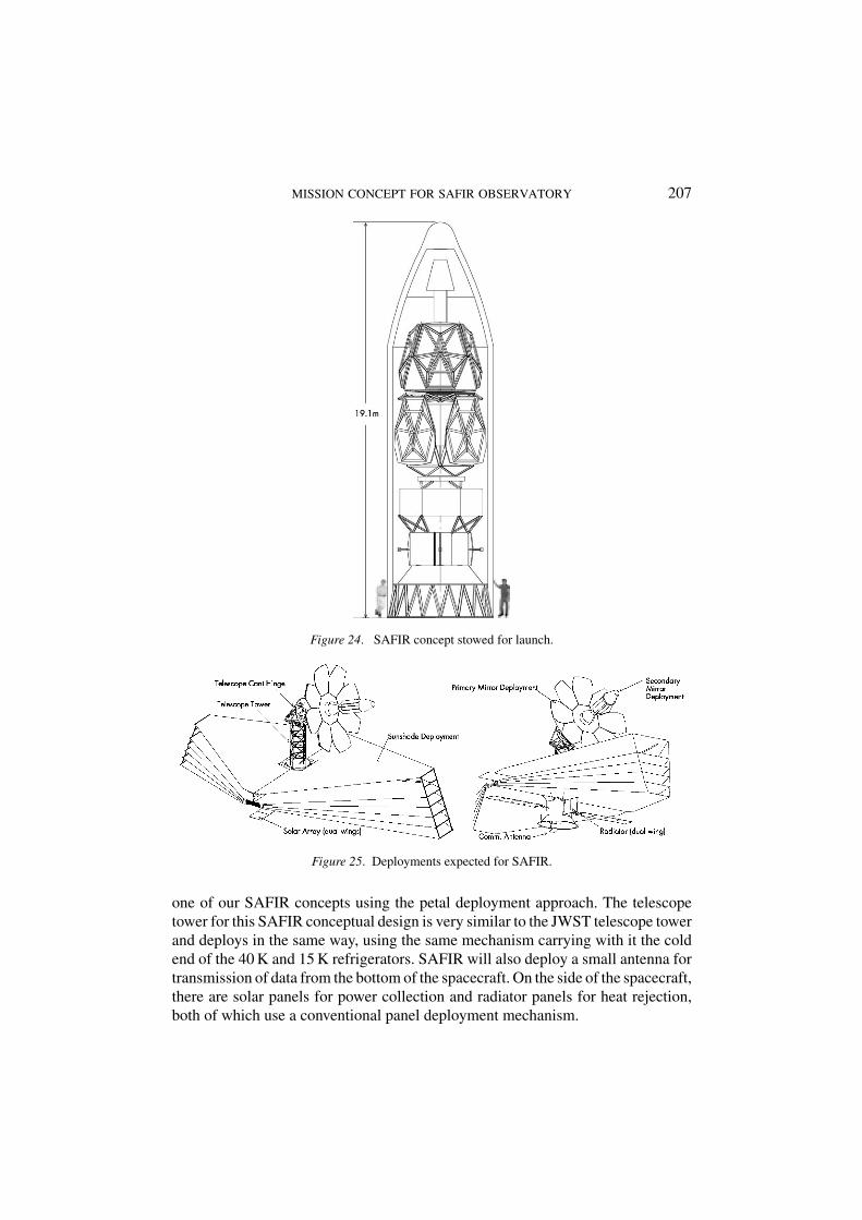
Figure 24. SAFIR concept stowed for launch.
Figure 25. Deployments expected for SAFIR.
one of our SAFIR concepts using the petal deployment approach. The telescopetower for this SAFIR conceptual design is very similar to the JWST telescope towerand deploys in the same way, using the same mechanism carrying with it the coldend of the 40 K and 15 K refrigerators. SAFIR will also deploy a small antenna fortransmission of data from the bottom of the spacecraft. On the side of the spacecraft,there are solar panels for power collection and radiator panels for heat rejection,both of which use a conventional panel deployment mechanism.
208 D.J. BENFORD ET AL.
6.13. INTEGRATION AND TESTING
A great deal of work has already been done to design and plan for JWST integrationand testing. Because our primary conceptual design is based largely on JWST, it isnot surprising that SAFIR’s integration and testing has many of the same challenges.We have made a detailed integration and test plan for the SAFIR concept discussedabove, which is quite similar to JWST’s plan. The assembly of SAFIR can follow thesame basic flow and use many of the same solutions as JWST. Some of the assemblychallenges are made easier because of SAFIR’s less stringent optical requirements.Some will be made more difficult because SAFIR is larger than JWST.
JWST’s testing procedure can also be used as a basis for testing the SAFIRobservatory. The purpose of any verification program is to ensure that the requiredperformance of the system will be achieved in flight. The size (10 m vs. 6.5 m) andoperational temperature requirements (4 K vs. 35 K) of SAFIR are different fromJWST, so the facilities designed for JWST may have to be modified to accommodateSAFIR. JWST will require thermal test capabilities ranging from ambient tempera-ture to liquid helium temperatures. The Plum Brook Facility at NASA Lewis and theRaytheon 50′ diameter spherical thermal vacuum chambers have some promise ofbeing able to accommodate SAFIR testing, with the modifications made for JWST.The basic JWST approach, which uses other facilities designed for the testing ofthe sunshade and instrument structure, is likely to be viable for SAFIR, with manyof the same facilities and setups. “A Strawman Verification, Integration and TestProgram For NGST” (1991) describes a JWST integration and test plan includ-ing facilities, setups, and justification. Due to the lightweight nature of the JWSTtelescope and its resultant flexibility, operation in gravity will require the use ofcarefully designed test supports and self-weight compensators, which will equallyapply to SAFIR.
6.14. MASS AND POWER
Running the cryocoolers, instruments, and the spacecraft subsystems requires sub-stantial power. Trade studies have led us to decisions which require more power,but fewer deployments and less design complexity. The power is not hard to obtaingiven the size of the SAFIR observatory. Solar arrays with total area of 17 m2 ontwo standard deployed booms meet the current calculated design estimates with40% reserve. The estimated power consumption of the entire SAFIR observatoryis 3500 W, dominated by around 2000 W for the cryocoolers. This is a very con-servative estimate of the total power required, and may be high by as much as afactor of 3. Mass is more difficult to estimate, as very little of the detail needed todo this has been fleshed out. However, we are confident that no major subsystemshave been omitted, and so we believe that a conservative estimate of the mass isaround 4000 kg. The mass and power budgets are detailed in Tables III and IV.

MISSION CONCEPT FOR SAFIR OBSERVATORY 209
TABLE IV
SAFIR observatory conceptual design power estimates
6 .15. BUDGET
The major systems in SAFIR—for example, the telescope or sunshade—are ex-pected to draw heavily on JWST development and experience. As a result, there willbe substantial cost savings for a JWST-like SAFIR. In 1999, Goddard Space FlightCenter estimated the budget for SAFIR for the UVOIR panel of the Decadal Survey(NAS Decade Report, 2001) which concluded that the costs would be $310M forconstruction, $85M for launch, and $100M for 5 years of operations. They drew ontheir experience estimating the cost of JWST, so the relative comparison of the twomissions is also meaningful. They assumed that no additional development wouldbe required beyond that for JWST, although the report indicated that this was prob-ably not entirely correct. A significant development program specific to SAFIR,perhaps even departing significantly from the JWST telescope architecture was as-sumed to be half that for JWST, or an additional $125M, for a total SAFIR missioncost of $620M. This estimate was made when the best estimate of the UVOIR panel

210 D.J. BENFORD ET AL.
for JWST was $1114M. The Decadal Survey committee also recommended a bud-get over the decade for technology development that would support SAFIR (andother projects in the far-infrared and submillimeter) of $140M, including $10M fordetectors, $50M for space refrigerators, and $80M for large, lightweight optics.
Our estimate of the SAFIR cost was made by direct line-item comparison toJWST. The result was that SAFIR would cost 80% of JWST. However, this estimatedepends strongly on factors that are beyond the program’s control, such as itsfunding profile and prior technology investments.
7. Project Status
Investment in the development of the various design concepts is a critical need inthe near term. The basic decision of a SAFIR architecture must be made as soon aspossible to guide further development of the mission. We have based our concepton JWST, so that its developments may result in approaches that can be readilyadapted to the far-infrared, with the differing requirements of (1) colder operat-ing temperature; (2) relaxed image quality; and (3) larger aperture. These threeimportant differences, however, may drive SAFIR to a very different architecture.For instance, although autonomous deployment is a possibility, opportunities forreduced cost and risk through in-space assembly can also be explored.
A team consisting of members from NASA/GSFC, NASA/JPL, and universitieshas proposed to conduct a deeper study of SAFIR, leading to a more refined missionconcept than the one presented here. This will be the dominant SAFIR activity dur-ing 2004. Also, there is a high level of interest in the far infrared and submillimeterboth in Europe and Japan, making it timely to consider possible international col-laborations. Such cooperation has already been fruitful in the infrared and sub-mmfor Herschel, Planck, and ALMA.
8. Summary
We have developed a conceptual design for the SAFIR observatory, based onJWST’s current designs, and made a detailed analysis of the changes necessaryto produce SAFIR. The differences between SAFIR and JWST are simple to sum-marize. Primarily, SAFIR must be much colder, and therefore will require activecoolers and a more capable sunshade. The sunshade itself, the largest component ofJWST, can be remarkably similar in architecture. The coolers are all feasible usingnear-future technology. Secondly, SAFIR requires a different complement of in-struments, which will take new detectors needing substantial development. Finally,SAFIR’s telescope will be larger than JWST’s, but the launch vehicle selected canaccommodate this change. Other aspects of SAFIR’s telescope—the mirror itself,the pointing tolerances—are made simpler by the longer wavelengths and thereforeless stringent requirements of SAFIR versus JWST. Table V summarizes the salientparameters of the SAFIR mission.

MISSION CONCEPT FOR SAFIR OBSERVATORY 211
TABLE V
Mission parameters for achieving SAFIR science goals
Primary mirror diameter 10 meters
Wavelength coverage 20–800 microns
Angular Resolution 1′′ at λ ≤ 40 µm, diff. limited at λ > 40 µm
Science instrumentation Camera and Spectrographs
Mission duration 5–10 years
Orbit L2 libration point halo, 870 000 km Y amplitude
Payload mass 4900 kg (conservatively, with contingency)
Average power 3600 W (with contingency)
Planned launch year 2015 (approximate)
Launch vehicle Delta-IV Heavy, 19 m fairing
Funding, technology developments, and the schedule of JWST will all drive thelaunch date of SAFIR. Based on JWST’s 15 year start-to-launch timescale, andassuming some improvement due to JWST’s technology developments, SAFIRcould launch as early as 2015.
“SAFIR will study the relatively unexplored region of the spectrum between30 and 300 µm. It will investigate the earliest stage of star formation and galaxyformation by revealing regions too shrouded by dust to be studied by JWST, andtoo warm to be studied effectively with ALMA. It will be more than 100 times assensitive as Spitzer or the European [Herschel] mission. To take the next step inexploring this important part of the spectrum, the committee recommends SAFIR.The combination of its size, low temperature, and detector capability makes itsastronomical capability about 100 000 times that of other missions and gives ittremendous potential to uncover new phenomena in the universe.” (NAS DecadeReport, 2001, pp. 39, 100).
SAFIR will make profoundly important contributions to the goals of both thestructure and evolution of the Universe and the origins themes of NASA spacescience, with clear science priorities and exciting science goals that are intellectuallyaccessible to the greater public. It will also showcase new technology in dramaticadvancement for large or cryogenic telescopes, but achieved through realizabletechnology developments of a moderate scale. We have developed a SAFIR conceptat NASA’s Goddard Space Flight Center, demonstrating that a JWST-based is afeasible approach to achieving this important mission.
Acknowledgements
We would like to thank the SAFIR Mission Concept Study Team at NASA/GSFC,for their work in bringing the concept detailed above to completion. They in-clude: Ed Canavan, Dave Green, Cathy Marx, Mark Matsumura, Lee Mundy, Keith

212 D.J. BENFORD ET AL.
Parrish, Joe Pelliciotti, Juan Roman, and Kurt Ruckleshaus. Guidance for the sci-ence requirements of this concept, and some scientific background information, re-sulted from substantial contributions from George Rieke, Paul Harvey, Dan Lester,and Lee Mundy.
References
A Strawman Verification, Integration and Test Program For NGST, NGST Monograph No. 4, 2000.Amato, M.J., Benford, D.J., Moseley, S.H. and Roman, J.: 2003, An Engineering Concept and Enabling
Technologies for a Large Single Aperture Far-IR Observatory (SAFIR), in: IR Space Telescopesand Instruments, Proceeding of SPIE 4850, 1120–1131.
Blain, A.W., Ivison, R.J. and Smail, I.: 1998, MNRAS 296, L29–L33.Dipirro, M.: 2003, Cryogenic Technology: Ongoing Developments for the Next Decade, in: D.J.
Benford and D.T. Leisawitz (eds.), New Concepts for Far-Infrared and Submillimeter SpaceAstronomy, NASA/CP212233.
Dowell, C.D. et al.: 2003, Proc. SPIE 4855, 73–87.Dragovan, M.: 2002, Proc. SPIE 4849, 1–7.Harvey, P.M., Rieke, G.H., Lester, D.F. and Benford, D.J.: 2003, Proc. SPIE 4850, 1097–1108.Harwit, M.: 1981, Cosmic Discovery: The Search, Scope, and Heritage of Astronomy, Basic Books,
New York.Kooi, J.W., Kovacs, A., Kaye, S., Dama, J., Edgar, M.L., Zmuidzinas, J. and Phillips, T.G.: 2003,
Proc. SPIE 4855, 265–278.Looney, L.W. et al.: 2003, IR Space Telescopes and Instruments, Proc. SPIE 4857, 47–55.National Academy of Sciences: 1991, The Decade of Discovery in Astronomy and Astrophysics,
National Academy Press, Washington DC.National Academy of Sciences: 2001, Astronomy and Astrophysics in the New Millennium, National
Academy Press, Washington DC.Richards, P.L.: 2003, Future Far-Infrared/Submillimeter Direct Detectors, in: D.J. Benford and
D.T. Leisawitz (eds.), New Concepts for Far-Infrared and Submillimeter Space Astronomy,NASA/CP–212233, pp. 325–328.
Rieke, G.H. et al.: 2003, Charting the Winds that Change II: the Single Aperture Far-Infrared Obser-vatory (SAFIR), in: D.J. Benford and D.T. Leisawitz (eds.), New Concepts for Far-Infrared andSubmillimeter Space Astronomy, NASA/CP212233.
Shirron, P., Canavan, E., DiPirro, M., Jackson, M., King, T., Panek, J. and Tuttle, J.: 2002, Cryogenics41, 11–12, 789–795.
The Community Plan for Far-Infrared and Submillimeter Space Astronomy: 2003, in: D.J.Benford and D.T. Leisawitz (eds.), New Concepts for Far-Infrared and Submillimeter SpaceAstronomy, NASA/CP212233.
Young, E.T., Rieke, G.H., Cadien, J., Dole, H.A., Englebracht, C.W., Gordon, K.D., Heim, G.B.,Kelly, D.M. and Stansberry, J.A.: 2003, Proc. SPIE 4850, 98–107.