COLLECTING OLD REFRACTORS - Brayebrook Observatory
241
COLLECTING OLD REFRACTORS CHRISTOPHER J. R. LORD
-
Upload
khangminh22 -
Category
Documents
-
view
1 -
download
0
Transcript of COLLECTING OLD REFRACTORS - Brayebrook Observatory

COLLECTINGOLD REFRACTORS
CHRISTOPHER J. R. LORD

COLLECTINGOLD REFRACTORS
CHRISTOPHER J. R. LORD
FIRST PUBLISHED 2015
i

PREFACE
Histories of the telescope rarely consider the refractor in its entirety, and concentrate on the astronomical telescope almost exclusively. Academics who write their histories never consider collectors, and presume their intended readership are only interested in the development of the telescope and its use for astronomical research from an academic standpoint.
This book is written for collectors of old refractors. The refractor did not develop solely as an astronomical telescope, indeed the market has always been primarily terrestrial, be it marine, military, target shooting, hunting or bird watching. However astronomical refractors are also included because they too can be collectable.
The author has collected old refractors since the mid 1960’s, and has made an intensive study of their optical and mechanical construction. Having a preference for refractors made by English instrument makers, most of the examples discussed are of English manufacture.
It is the author’s hope this little book will aid in the indentification of old refractors, their date and place of manufacture, and their intended purpose. Advice is also given as to the best places to find old refractors, tips on buying or bidding at auction, and the best ways to repair and refurbish old refractors, the sort of things to expect, to look out for, and what to avoid.
What are not considered are observatory class astronomical refractors because they aren’t collectable, indeed they tend to be white elephants. The purpose of collecting old refractors is not simply to learn about them, but for their investment potential. To be bought at the right price and sold for a profit. ii

ACKNOWLEDGEMENTS
The author is pleased to acknowledge Rolf Willach, optical engineer and independent scholar for his assistance in describing C17th developments in terrestrial refractors. He worked for several years in the Department of Physics at the Institute of Astronomy in Bern, and has written extensively on the history of the development of optics and the early refractor.
For their inspiration and encouragement the author would also like to record his thanks to fellow collectors Christopher Madden, creator of the Fleaglass scientific instrument trading website, and Thomas Moon, machinist. Also to Paul Schofield, fellow collector. Both Tom & Paul for their help in restoring some of the refractors in the author’s collection. And last but not least to the late Rob Carter who read the draft and offered sage advice.
A special thanks is given to Reginald J. Cheetham, author of “Old Telescopes” long out of print and impossible to obtain, whose established identification format the author has followed.
iii

CONTENTSSECTION
Page• TYPE 1 GALILEAN 1• TYPE 2 KEPLERIAN 5• TYPE 3 SCHEINERIAN 6• TYPE 4 SCHYRLEAN 8• TYPE 5 HUYGENIAN 11• TYPE 10 ACHROMATIC TERRESTRIAL 19• TYPE 11 ACHROMATIC ASTRONOMICAL 25• TYPE 12 RAMSDEN/SIGHTING 28• TYPE 13 ACHROMATIC GALILEAN 30• ACHROMATIC DOUBLET OPTICS 31• TYPES OF ACHROMATIC DOUBLETS 36• ANTIQUE BRASS REFRACTOR DESIGN 42• EYECUP STYLES 53• OBJECT GLASSES 56• SIGNATURES 59• BRASS JOBBER’S ASSEMBLEY MARKS 62• CANNISTERS & TRUNKS 63• EXAMPLES OF OLD REFRACTORS 64• UNSIGNED SIMPLE SINGLE DRAW 65• COMPARISON of FRODSHAM & J. LILLEY & GILLIE SINGLE DRAW MARINE 66 • UNSIGNED SINGLE DRAW MARINE 68• SIGNALLING & POCKET REFRACTORS 70• OFFICER of the WATCH TELESCOPE 72• TABLE TOP REFRACTORS 74• ASTRONOMICAL REFRACTORS 84• TYPES of STAND 93• PILLAR & CLAW STANDS 94• FLAG PANEL MARINE 97
iv

CONTENTSSECTION
Page
• BUYING ANTIQUE & VINTAGE BRASS REFRACTORS 98• CLEANING, RENOVATION & MAINTENANCE of ANTIQUE & VINTAGE BRASS REFRACTORS 101• EXAMPLE OF BEFORE & AFTER CLEANING & RENOVATION 108• CLEANING, RENOVATION & MAINTENANCE of ANTIQUE & VINTAGE BRASS REFRACTORS (cont.) 111• NOTES on BRITISH INSTRUMENT MAKERS 113• USEFUL REFERENCE WORKS 114• APPENDIX-1 118• APPENDIX-2 122• APPENDIX-3 ANTIQUE TELESCOPES IN MY COLLECTION 132• NOTES 220• BIBLIOGRAPHY 221• LIST of FIGURES 223• INDEX 225
v

COLLECTINGOLD REFRACTORS
INTRODUCTION
The purpose of this little book is to provide information on the design and construction of old refractors, and to enable their identification, either in collections or in the antique scientific instruments trade. Advice is also given as to the practicalities of restoration and maintenance of old refractors.
The English telescope making trade has its origins in the mid C17th. Developments in optical and mechanical arrangements, acquired from continental makers, became established in London, that influenced regional manufacturies. Styles evolved and progressed throughout the C18th and C19th, again driven by London instrument makers. Because of delays in trends and issues concerning patent rights, there is overlap in styles between London and provincial makers. Unsigned refractors are therefore difficult to date with any certainty. Even signed refractors can only be dated within a certain period, depending when a particular maker’s business flourished.
It was also common practice for instrument makers to obtain parts from “jobbers”. Jobbers were tradesmen who specialised in making the components of certain classes of instrument. In the case of refractors a lens jobber would make the object glasses and eyepiece lenses, a brass jobber would make the tubes and fittings. These would then be assembled in the instrument maker’s workshop. Workshops in the late C17th thru’ early to mid C19th were domestic. Entire families would be engaged in various aspects vi

of instrument making. Instrument making was a family business, and many of them thrived for several generations. Instrument makers intentionally strove to make refractors of particular styles, identifiable as their work. But, because the component parts were typically supplied by jobbers, there was an inevitable similarity between different makers. Furthermore, an individual maker’s refractor, although made in quantity over the years, and looking superficially identical, are each and everyone “one offs”, i.e. their parts are not interchangable.
It is not uncommon to find old refractors that have been repaired by marrying parts of different, yet similar old refractors. This is not necessarily detrimental to its value, especially if it is unsigned. It depends on how well the restoration has been done.
In order to appreciate details in their construction, some familiarity with refractor parts, how they were made, and how their design evolved from the late C17th thru’ late C19th is essential.
The thirty three sections of this book are devoted to providing that information. Definitions of components, the ages of particular styles, their historic origins, and developments. These are arranged where possible in chronological order of introduction or invention.
Ascertaining details of a terrestrial refractor’s optical construction normally entails dismantling, cleaning and reassembly. Advice on dismantling and assembling old refractors and some information on restoration or refurbishment techniques are provided in the final three sections.
Information on sources of trade biographies are provided in the BIBLIOGRAPHY. vii

TYPE 1 GALILEAN
So called because the physicist Galileo Galilei (1564-1642), in May 1609 received a letter from a former student, Jacques Badovere, about a “Dutch Trunk” and endeavoured to obtain one through an intermediary, Paolo Sarpi. Having failed to acquire one, Sarpi supplied a description of it’s construction.
The original “Dutch Trunk” had been demonstrated to a delegation of Prince Mauritz of Nasseau, for the Zeeland States General on October 2nd. 1608. The man claiming its invention was Hans Lipperhey, a spectacle maker, who applied for the patent right, on September 25th, 1608. The claim was declined on the grounds the instrument was too easily copied so could not be kept secret. Counterclaims soon followed from Jacob Metius of Alkmaar (17th October 1608) and yet a third person. Zacharias Jannsen, several decades later.
Galileo, in his, “Sidereus Nuncius” claimed to have re-invented the refracting telescope, based upon the principles of refraction, a wholely bogus claim, since the geometric optical principles necessary to design a telescope were unknown at the time, and Galileo never did provide details of how he designed his telescope.
Galileo was the first person to publish detailed observations of the Sun, the Moon, Jupiter, Venus and star clusters, The Pleiades, Praesepe, and parts of the constellation Orion, in April 1612.
The erecting refractor comprising a convex object glass and a concave eye lens is named in his honour.
1

OPTICS OF THE GALILEAN REFRACTOR
figure 1
2

OPTICS OF THE GALILEAN REFRACTOR
figure 2
The ideal arrangement of a Galilean telescope consists of a bi-convex objective and bi-concave eyepiece. In practice the lens forms differ, in an attempt to obtain a sharper image.
The optics of the Galilean Telescope comprise a positive long focus objective and a negative eye lens. Parallel rays from a remote object are refracted through the object lens to a focus. Before they reach the focus they are intercepted by the eye lens and diverged back to a parallel beam where they enter the eye. Because the eye lens has to be placed before the focal plane of the objective the exit pupil is not real. It appears to float in image space in front of the eye lens. It is not possible to place the eye at the exit pupil, so if the exit pupil diameter exceeds that of the eye pupil, the field of view (fov) is vignetted. (fig.1)
The exit pupil lies fe(m-1)/m before the eye lens. The pupil of the eye has to be placed as close to the back surface of the eye lens as possible. What the observer sees is the image of the exit pupil projected onto the entrance pupil, and because the eye is focussed at infinity, the edge of the exit pupil is out of focus. The apparent fov accessible to the eye is given by the tangent of the ray height at the exit pupil divided by the distance to the eye’s centre of rotation. (fig.1) 3

Magnification & field of view (fov) of a Galilean refractor
Refer to fig. 1.
The image is erect. The paraxial optical path distance equals the sum of the lens focii, i.e. f1 + (-f2). Longitudinal spherical (LSA) and chromatic (LCA) aberrations to some extent cancel one another because the eyepiece comprises a negative single eye lens. Keeping the lens curves shallow, i.e. having a large focal ratio object glass (OG) results in LSA and LCA being held close to the Rayleigh limit. Terrestrial Galileans of the mid C17th have f/ratios ~30, and astronomical Galileans ~60. (fig.2)
The form is most commonly found nowadays in cheap Opera glasses and field glasses. 4

TYPE 2 KEPLERIAN
figure 3
Johannes Kepler (1571-1630) worked out the principles upon which the Dutch telescope functioned, during the summer-early autumn 1610, and published his work as 'Dioptrice' in September 1611.
Because Kepler worked from first principles he understood a fully functional telescope had to have both an entrance and an exit pupil, and that only an afocal system in which the objective produced a real image, could satisfy this condition. (fig.3)
Because the Keplerian, or astronomical refractor has a real prime image and an exit pupil, the field is much wider than the Dutch refractor and also unvignetted. Unfortunately the retinal image is inverted, and LSA & LCA are additive. When used in it’s astronomical form the focal ratio needs to be ~100.
Francesco Fontana (1585-1656) is supposedly the first astronomer to take up Kepler’s suggestion in 1646, “Novae coelestium, terrestriumque rerum observationes, et fortasse hactenus nonvulgatae”. Fontana claimed to have used a positive eye lens from 1608, predating Kepler’s Dioptrice 1612, and Christopher Scheiner, 1617, and de Rheita, 1645. However the earliest published observationsby Fontana dates from 1629. 5
TYPE 3 SCHEINERIAN
Kepler realised this would be a drawback, despite the much more commodious field of view, so advocated a three lens telescope comprising a single lens erector and a single eye lens.
figure 4
Kepler's refractor was first adopted by Scheiner around 1617-18 and his three lens refractor about 10 years later. Kepler’s three lens refractor is misattributed to Scheiner as a consequence. Scheiner refers to his use of a three lens refractor in “Rosa Ursina” published in 1630.
LSA & LCA are worse than Kepler’s two lens refractor.
As in all refracting telescopes except the Galilean, the linear magnification is the ratio of the OG and eyepiece focii.
The eyepiece apparent fov is given by:
€
θ =6πsin−1 Ed
2Fe where
€
Ed is the field stop diameter &
€
Fe
is the eyepiece effective focal length.
6

The effective focal length of any two lens combination is given by:
€
efl =f1. f2
f1 + f2 − d
where
€
f1 &
€
f2 are the lens focii &
€
d their separation.
The real fov is given by the apparent fov divided by the linear magnification.
Hand held terrestrial Keplerian refractors have lowish powers, in the range x5 to x30. The single and two lens Keplerian eyepiece has an apparent fov ~ 20º.
7

TYPE 4 SCHYRLEAN
figure 5
In 1645 John Burchard von Schyrle (1597-1660) published 'Oculus Enoch et Eliae Sive Radius Sidereomysticus'. The work is that of a Capuchin monk known more widely as Anton Maria Schyrleus de Rheita. Schyrleus de Rheita invented a two lens compound eyepiece, and three, four and five lens refractors that could be used as either terrestrial (day) or astronomical (night) telescopes, and advocated those wishing to purchase such refractors to order them from the Augsburg instrument maker Johannes Wiesel.
What did Schyrleus de Rheita's lens arrangements comprise?
Firstly his two lens compound eyepiece which has a wider useable field than the Keplerian (fig.5).
It comprises a pair of equi-convex lenses of equal focal length separated by slightly less than their focal lengths, producing an inverted image with less lateral colour error than a Keplerian of equal power.
Next de Rheita's four lens telescope, with a two lens erector and a Keplerian eyepiece. The erectorcould be removed, converting the refractor into 8

an astronomical telescope. This is the basis of the so-called 'Day or Night' telescope (fig6).
figure 6
figure 7a
Then we have the five lens telescope, comprising a two lens erector matched to a two lens compound eyepiece. Each lens has the same focal length, and the lens spacings are equal to their focal lengths (fig.7a). Because the third lens in the eyepiece section lies at the focal plane of the second erector lens, any dirt or defect would be thrown into sharp focus, so the lens arrangement was altered slightly. (fig.7b)
figure 7b 9

The erector and third lens could be removed, leaving a Keplerian astronomical or night telescope.
figure 7c
Campani adopted a three lens erecting eyepiece similar to de Rheita's four lens refractor, with a two lens erector and a Keplerian eyepiece, equal focii, and double focii separation. Campani's telescopes were sometimes supplied with a high power version giving twice the magnification in which the second and third lens (comprising the erector) were separated by the sum of their focii, the second lens having twice the focal length of the third. (fig7c).
Four and five lens refracting telescopes were to be the mainstay of telescope makers for the next hundred years. Undoubtedly the best commercially successful refractors of this type were made by Johannes Wiesel. Subsequently many instrument makers turned their hand to making the same types of refractor.
Because of poor figuring of OG’s, they were habitually stopped down, by as much as 50%. A stop plate was either placed immediately in front, or behind the OG.
10

TYPE 5 HUYGENIAN
Huygens' improvements to the early refractor
Christiaan Huygens is famous for developing the wave theory of light and the inelastic medium through which it purportedly propagated, the 'Luminiferous Aether'. Of equal importance is the work he did with his brother Constantijn, grinding and polishing objectives of enormous focal length, used in his Aerial telescopes. Similar telescopes with an open lattice framework were made by Hevelius. Both improved upon the lens grinding and polishing machine devised by Schyrleus de Rheita.
Christiaan Huygens also published scaling rules for the astronomical refractor, by which, using lenses of small radius of curvature, the problem of LCA could effectively be minimised.
Christiaan Huygens' scaling rules for the astronomical telescope; from Thomas Dick, 'The Practical Astronomer' p65 (table 1):
"The focal length of the astronomical telescope must be increased in proportion to the square of the increase of their magnifying power; so that, in order to magnify twice as much as before with the same light and distinctness, the telescope must be lengthened four times; to magnify 3 times as much, 9 times; and to magnify 4 times as much, 16 times...." and so on.
These refractors were not diffraction limited in the sense of meeting the Rayleigh criterion.
11

table 1
Taking the Conrady limit for depth of focus:
€
Δf = 8 fD
2
λ
& for Borosilicate crown:
€
nd =1.5168nC =1.51432nF =1.52283
longitudinal chromatic aberration:
€
fr − fb = fdnF − nC( )nd −1( )
=Δf
Δf = 0.0165 fd& taking:
€
Δf = 0.0165 fdfr = +0.005 fdfb = −0.012 fd 12

€
∴0.00858λ
=fD
2
from which, when:
€
λ = 21.6µ"f = 49.2D2
This figure is slightly higher than that adopted by Huygens,
€
FL = 41.4D2 (where
€
D is the aperture in inches)
However the magnifying power was also governed by the aperture. From Huygens' table M = 37.2 D, and of course, because the focal length increased as the square of the aperture, the focal ratio was directly proportional to the aperture, N = 41.4 D.
So for instance Hevelius' 150 foot refractor would have had an object glass about 6".5 aperture & a magnifying power approximately X245. The lens focal ratio would have to be f/270!
The Huygenian eyepiece
The next significant improvement to the refractor was also made by Christiaan Huygens, around the mid to late 1650's. His work was made known to the Royal Society in 1662, but the particulars of his work were not generally known until after his death in 1695. The original 1666 manuscript ‘Dioptrica Oeuvres Complétes’ was not published until 1703.
The Huygenian eyepiece comprises a pair of convex lenses (they can be any shape, but plano-convex is the most common, plano towards the eye): (fig.8a)
13

figure 8a
Christiaan Huygens was primarily interested in increasing the magnifying power of his refractors. To obtain higher powers meant using ever longer focal length objectives because shortening the focal length of the eyepiece produced more colour error. Despite his work on refraction Huyghens didn't know what caused colour error. But like every other worker in the field, he knew short focal length lenses produced more of it.
The problem obviously was using a Keplerian eyepiece with a very long focal length objective resulted in a fairly modest field of view, which made the telescope awkward to point and track a planet or star.
Huygens' ingenious solution lay in interposing a positive lens immediately in front of the objective's focal plane. This had the effect of greatly reducing the effective focal length of the objective, but because the lens lay close to the objective's focus, colour error was not significantly increased. The reformed image behind the second lens was then highly magnified by a positive eye lens. The effect of the second or 'field' lens was, in reducing the effective focal length of the objective, to greatly widen the real field of view, and ensure it was unvignetted.
14

But Huygens’ lens arrangement also produced a solution to lateral colour error, in which red and blue images have different sizes. Huygens was unaware of this property, which was only discovered by George Biddell Airy in the 1820's. Airy worked out that if the separation of the field and eye lens was half the sum of their focii, the different coloured images were of equal size.
His final piece of genius was to also provide a correction for variation of magnification with ray height, or coma. The ratio of the focal lengths of field and eye lens is equal to the fourth root of the eyepiece magnification. (fig.8b)
The one drawback of the Huygenian eyepiece is the location of the field stop, between the field and eye lenses. This makes it awkward to introduce a wire micrometer, and even if one did manage to do so, the wires would be marred by false colour.
Optimum separation of elements in a Huygenian or Ramsden eyepiece for zero lateral chromatic aberration:
from, eyepiece effective focal length:
€
efl =f1. f2
f1 + f2 − dwhere: f1 = field lens focal length
f2 = eye lens focal lengthd = separation of eye and field lenses
for every increment in wavelength
€
Δλthe effective focal length increases by
€
Δf
€
∴ 2d.Δf =f1. f2 1+Δf( )2
f1 + f2( ) 1−Δf( )− d 15

and neglecting powers of:
€
Δf
€
f1 + f2( ) 1−Δf( ) −d = f1 + f2 −d( ) 1+2Δf( )2d.Δf = f1 + f2( )Δf2d = f1 + f2d = 1
2 f1 + f2( )
figure 8bFive lens terrestrial refractors originally with Schyrle four lens eyepieces were subsequently replaced with the Schyrle-Huygens four lens eyepiece.
figure 9Peter Dollond in the late C18th developed the Pancratic four lens eyepiece, similar to Schyrle’s 16

but possessing the curious feature of the chief ray crossing points always remaining close to the optical axis regardless of the ray height. This enables small aperture stops to be fitted between the erector lens pair, and in front of the field lens and eye lens, which provides a very dark night time backdrop to the field of view. Stray light can be effectively prevented from entering the field lens. The erector could be removed and the eyepiece section refocused, for use as an astronomical telescope. Charles Tulley made a variable power Pancratic designed by William Kitchiner in 1821. (fig.9)
The two lens erector section also acts as an image amplifier. Wider separation raises magnification. Calculating the effective focal lengths of a Schyrle-Huygens or Pancratic eyepiece are given in fig.10.
Hand held refractors made after the invention of the achromatic object glass by John Dollond in 1758, mostly have achromatic OG’s, either doublets or rarely, triplets. However it is also not always apppreciated single lens OG hand held refractors with Schyrlean 3 or 4 lens eyepieces continued to be made well into the C19th.
The largest refractors made in the C18th had achromatic OG apertures no more than 4 inches. This was because optical crown and flint glass blanks suitable for grinding and polishing in larger sizes could not be obtained. Flint glass blanks especially.
This limitation was not a problem for hand held refractors, but it was a limiting factor in making larger astronomical refractors, and it wasn’t until the early C19th that optical glass technology improved to the point where larger, observatory class astronomical refractors were built. 17

figure 10
18

TYPE 10 ACHROMATIC TERRESTRIAL
figure 11
The problem of lens telescopes and the practicality of using mirrors instead was tackled by Isaac Newton.
Newton, following correspondence with Robert Hooke, the Royal Society’s Curator of Experiments, caused him to conduct light experiments using glass prisms.
Newton discovered white light was an admixture of the colours of the rainbow (referred to in the Latin as “spectrum” ).
He incorrectly concluded from his Experiment VIII, that because dispersion was proportional to refraction, no combination of different transparent media could correct chromatic aberration.
19

Because of his rivalry and the animosity he felt towards Hooke, Newton did not publish his optical experiments until 1704, following Hooke’s death the previous year.
Single element object glass refractors, known as simple refractors cannot be scaled for use as high power astronomical telescopes. Their inherent LSA & LCA mars any high power image. The answer lay in finding a way of correcting the aberrations of the single lens object glass. This was eventually accomplished by John Dollond in 1758. But the circumstances of Dollond’s invention are mired in controversy.
Newton’s Experiment VIII implied there was no point trying to improve the refracting telescope. However there was one niggling doubt. Early studies of the eye’s lens suggested it might be possible to make a lens that did not split light up into its component colours. This was based on the erroneous observation that the eye does not exhibit chromatic aberration, experiments conducted in the late C17th by David Gregory.
Chester Moor Hall 1729 designed a doublet lens with a crown glass bi-convex and plano-concave flint. In 1733, Hall placed an order with two Spitalfield lens makers, William Scarlett & James Mann. Both sub-contracted the work to a lens jobber called George Bass. Bass realised the lenses fitted together, but failed to see the significance. Bass enquired of his employers and was told the order was for Hall. Hall, satisfied his lens was practicable, placed a further order with John Bird, who passed it on 3 years later to James Mann, who then passed it onto his apprentice James Ayscough.
Hall never did see his lens finished, although Ayscough purportedly exhibited a “Spyglass” made with Hall’s lens in his shop window in 1754. 20

John Bird is reputed to have made a telescope using Halls’ lens for Vice Admiral Campbell c1755.
In 1747 Leonard Euler conducted similar experiments to Hall’s. Hall never published his work so Euler was unaware of his results.
Euler uncovered Newton’s erroneous Experiment VIII and presented a paper to the Berlin Academy of Science.
Samuel Klingenstierna in Sweden read Euler’s paper and developed a mathematical theory of a duplex colour correcting lens, also corrected for spherical aberration. (Only available in Swedish and later in Latin).
John Dollond, a spectacle maker in Spitalfield, read Euler’s paper and took issue with it. Later, on learning of Klingenstierna’s paper, he repeated Newton’s Experiment VIII, finding that flint glass possessed irrational dispersion disproportionate to crown glass.
John Dollond worked out the required refraction coefficients for a colour corrected doublet and made one in March 1758. A flint forward doublet.
Dollond presented a paper to the Royal Society and was awarded their Copley Medal.
Dollond was granted a Royal Patent by George III on 19th April 1758, securing him sole manufacturing rights for 14 years.
With his son, Peter, Dollond went into large scale manufacture of flint forward, and shortly thereafter, crown forward aspheric doublets. His lenses were dubbed “achromatic” by John Bevis in 1759. (fig.12) 21

Dollond achromats were copied by Benjamin Martin, and others, and marketed as “Dolland” or “Dolond”.
The Dollonds realised spherical aberration could be further reduced by using two crown lenses with shallower curves, either side of the flint. (fig.13)
John Dollond died in late November 1761. Peter Dollond began making triplet achromatics in 1765.
Law suits were brought against 7 London opticians who were making achromatic lenses and selling the telescopes without paying Peter Dollond a Royalty.
The Spectaclemakers’ Company petitioned the Privy Council. 33 petitioners sought the Patent’s revocation, but the Privy Council provaricated due to a political scandal involving the Attorney General.
Between 1764 & 1767 Peter Dollond won twelve separate suits and bankrupted one optician, after which he enjoyed a monopoly on the manufacture of achromatic refractors until 1772.
At the trial of Watkins & Linnell, Lord Camden upheld Lord Mansfield’s earlier ruling on Patent case law, "It is not the person who locks up his invention in his Scrutoire [Escritoire] that ought to profit by a patent for such invention, but he who brings it forth for the benefit of the public.”
J&P Dollond, later Dollond & Co., continued to make achromatic refractors into the 1860’s.
Peter Dollond did not make many triplets because of difficulty obtaining good crown and flint glass. The largest achromatics being roughly 3.75-inches aperture and 4 feet focal length. 22

Peter Dollond’s sister Sarah married Jesse Ramsden in 1766. Ramsden received a “Dowry” of 50% share in the Patent. Ramsden & Sarah Dollond became estranged in 1784.
Ramsden read a letter to the Royal Society in 1789 in response to a letter submitted by Peter Dollond defending his father’s claim.
The Royal Society refused to publish either letter since it was a trade dispute. Peter Dollond published his letter privately.
Ramsden craftily wrote a letter, repeating his version of events surrounding the invention of the achromatic lens, to “The Gentlemen” magazine under the pen name “Veritas” - Latin for truth.
Ramsden was able to manufacture achromatic telescopes before the Patent expired in 1772. Watkins, Linnell and others had to wait until April 1772 before they could do so, by which time Dollond had the optical glass market sewn up to his own advantage.
Throughout the late C18th & early C19th the by word for an achromatic refractor was a “Dollond ”.
John Dollond(I) was a French Hugenot silk weaver who joined his son Peter in business in 1752. He was admitted into the Spectaclemaker’s Co. in 1755. and traded as J. Dollond & Son.
Peter Dollond was the oldest son of John Dollond(I). He was admitted as a foreign Brother to the Spectaclemaker’s Co. in 1755. He was in business for himself 1750-52 & 1761-66. He took John Dollond(II) (1746-1804) his younger brother into partnership in 1766 and traded as P&J Dollond. He was in 23

partnership with John Dollond(II) from 1766 - 1804.
Jesse Ramsden was the great nephew of Abraham Sharp. Apprenticed to John Burton 1758, and subsequently turned over to Mark Burton. He was a regular visitor to John Dollond(I) between 1758-61. He set up his own business in Haymarket 1762, and married Sarah Dollond in 1766 receiving a share of the patent rights. They became estranged in 1784.
figure 12
24

figure 13TYPE 11 ACHROMATIC ASTRONOMICAL
figure 14
Achromatic astronomical refractors gained sway after John(I) Dollond’s invention, and especially so after the patent expired. Their focal lengths however were still long compared to modern astronomical achromatic refractors. 25

Peter Dollond and Jesse Ramsden produced excellent objectives, with focal ratios between 20 & 30.
As optical glass making improved during the early to mid C19th, it became feasible to make bigger doublets with greater light gathering and resolving power, and the development of different types of crown and flint glass enabled focal ratios to be reduced to about f/16.
Whilst larger terrestrial achromatics were supplied with a pillar & claw stand, astronomical achromatics were supplied with either an altazimuthal or equatorial mount, and large tripod, fitted with a smaller finder refractor, and hand operated slow motions. These embellishments were necessary to centre a celestial object in the field of view, and to follow the object in it’s diurnal motion across the heavens.
Astronomical achromatics were marketed according to their focal lengths, rather than aperture, which only became common practice in the latter half of the C19th.
Observatory class equatorial refractors were rare. Most astronomical refractors were between 2” & 4” aperture, and 3 feet to 6 feet focal length, and made to be portable. The longer achromatics made in the early C19th had split tubes that screwed together. This meant the storage case could be smaller, and easier for one person to carry.
Whereas a terrestrial telescope on a pillar & claw stand would be supplied with either a Schyrlean or Schyrle-Huygens erector, or a Pancratic erector eyepiece, an astronomical achromatic would be supplied with several Huyghenian eyepieces covering a magnification range from ~20x to ~150x. The highest power Huygenian eyepieces had next to no eye relief and restricted real fields of view. 26

From the mid C19th different types of astronomical eyepiece were introduced, firstly the Kellner or achromatic Ramsden, typically marketed as a “Comet” eyepiece, achromatic Huygenian, with a doublet eyelens, and in the late C19th the Abbé Orthoscopic and Steinheil Monocentric.
Accessories to enable celestial objects near the zenith to be comfortably observed were also introduced from the 1830’s, becoming common place by the end of the C19th. These were the star diagonal, comprising either a right angle prism or a 45º mirror, and a Herschel Wedge or Solar diagonal, which allowed 96% of the incoming sunlight to escape, 4% to enter the eyepiece, which was fitted with a dense eyelens filter, to provide “safe” solar viewing. Sun shades are potentially dangerous. The safest way to observe the Sun with an antique astronomical refractor is by eyepiece projection onto a white card. Moon filters were also supplied to cut down the dazzling brightness of the Full Moon.
Accesories to measure the separation and orientation of double stars, known as micrometers, either filar or double image, could be made to order. From the 1860’s onwards some firms also suplied spectroscopes and photometers. These specialist instruments are collectable, but have a limited appeal to most collectors.
Achromatic hand held refractors were a marked improvement on the single element simple hand held refractors. There was an overlap, with firms still supplying five lens refractors, single element OG and Schyrle erector four lens eyepiece, well into the C19th.
27

The achromatic refractor did not have to be stopped down to control LSA & LCA. These aberrations were minimised by the doublet or triplet OG itself. There was no need to design a five lens telescope, and whereas the OG & four lens erecting eypiece trade off LSA & LCA between them, both OG & eyepiece in an achromatic are each corrected for LSA & LCA, and the eyepiece for lateral colour.
Hand held achromatics could be made in larger sizes, providing a brighter image, either as a Day or Night telescope, and could be made shorter, and only really needed a single draw, even though multiple draw refractors were popular. More will be said about refractor styles in the descriptions section.
TYPE 12 RAMSDEN/SIGHTING
Achromatic refractors used for finder ‘scopes attached to astronomical refractors or in surveying theodolites, need an eypiece with an external field stop. The Huygenian is unsuited to having cross wires fitted because the field stop is internal, and viewed with a strongly curved eye lens. Cross wires would be blurred by both LSA & lateral CA.
Jesse Ramsden devised a simple two element eyepiece in 1783. It comprises a pair of plano-convex lenses, having the same focal length and same diameter, separated by half the sum of their focii. The plano surfaces face outwards. The focal plane lies on the plano face of the field lens. In this prescription there is zero eye clearance, and any dust on the field lens is in focus. Ramsden reduced the separation to between 60% and 80% the focal length, providing eye clearance and throwing dust out of focus, at the expense of a modicum of lateral colour.
28
The apparent fov is ~30º compared to ~40º for a Huygenian, but cross wires mounted at the field stop immediately before the field lens are in sharp focus, together with the image formed by the OG. (fig.15)
Finder ‘scopes usually have an adjustable Ramsden type eyepiece. The eyelens can be adjusted to suit the observer’s eyesight, and the objective is usually fitted into a sleeve that pulls out of the Finder ‘scope tube, to enable the image to be focused on the cross wire.
Sighting refractors and Finder ‘scopes are generally low power, no more than x7 to x10,, intended to obtain a fov wide enough to accommodate the image by sighting along the refractor’s tube. The image will be somewhere within the Finder field, and providing the Finder’s optical axis is collimated to the main refractor’s optical axis, once centred behind the cross wires, will be at or close to the centre of the field in the main ‘scope.
figure 15
29

Ramsden eyepieces are also found supplied with filar or bifilar micrometers, usually up to five different powers. Some makers also supplied an eyelens diagonal that slides across the face of the eyecap, to enable comfortable use near the zenith.
The cross wires of Ramsden eyepieces could also be illuminated, either by an Argand lamp shining light into the tube, or directly across the wires.
TYPE 13 ACHROMATIC GALILEANThe invention of the achromatic doublet (& triplet) made it possible to make compact monoculars with a low power Galilean eyepiece, either a single element or itself either doublet or triplet. They became fashionable from the 1780’s at the theatre, the opera house, or at the racecourse. They are frequently ornate, having numerous short drawtubes that collapse down to a small drum shape.
From the mid 1820’s they were largely superceded by Opera or Field Glasses, a simple form of binocular, again easily hand held and compact enough to fit into a handbag or pocket.
They are low power, no more than x8, usually only x4. The fov is typically ~ 5º. (fig.16)
figure 16 30

OPTICAL PRINCIPLES ACHROMATIC DOUBLETS
figure 17
Although the invention of the achromatic doublet was a protracted effort by some of the most learned and talented men of the age, it’s optical principles may be readily grasped.
A bi-convex lens made of crown glass would focus the image of a remote object in a spectrum of colours, red furthest and violet closest. It would not form a sharp image with all the colours meeting at a single focus. This is because the refractive index of any glass is wavelength, hence colour, dependent. Blue light has a higher refractive index than red light. This is because light of a higher frequency travels through atransparent medium faster than light of lower 31

frequency. A bi-concave lens will form a virtual image in the opposite manner to a bi-convex lens, with the red image closest and the violet furthest. If a lens were to be made of crown glass having a bi-convex element and a bi-concave element, in contact, light would pass through it without being dispersed into a spectrum of images. But because the concave element would cancel out the refractive power of the convex element, there would be no refractive power left, and no image would be formed.
The problem of producing an achromatic doublet is essentially that of combining a bi-concave element of a different type of glass to the bi-convex crown. A type of glass that spreads the spectrum of images out further. By deliberately making the bi-concave weaker than the crown in the ratio of the spread of colours of each glass type, there would still be some residual refractive power, yet essentially no colour error in the focused image.
The property of a lens by which the focused image is spread out in spectrum colour order, is due to dispersion. The trick to making an achromatuc doublet lay in measuring the dispersions of crown glass and a denser glass, called flint, a leaded glass produced by Ravenscroft more commonly known as lead crystal.
However there was a little more to it than merely cancelling out the colour error of the crown with a weaker negative flint. Lenses that have spherical surfaces bring the marginal rays to a shorter focus than the paraxial rays. This fault is called longitudinal spherical aberration, LSA.
Not only did the two elements have to cancel out colour error, known as longitudinal chromatic aberration, LCA, they also had to cancel out LSA. 32

The calculations to arrive at a workable prescription, the correct curves for each element, are fairly complex. John(I) Dollond approached the problem by making an adjustable water prism, combining it with a shallow crown prism, in an attempt to find the refractive and dispersive ratios. Eventually he settled on a crown-flint combination following a chance conversation with the lens jobber George Bass when he was in his shop looking for a pocket magnifier. Bass pointed out the flint hand lens produced noticeably stronger coloured fringes than a crown glass lens.
After a series of experiments John(I) Dollond arrived at a workable solution with a crown bi-convex having a ratio of curves 3:2 and the bi-concave flint 2:1. The solution was only approximate, but practicable for doublets of focal ratio ~20 to 30, although one of the concave surfaces had to be reworked to an aspheric figure to form a sharp image.
French mathematician Alexis Clairaut designed a contact doublet in 1762, and had several specimens built, by his opticians, Antheaulme and de l'Estang. Between 1764 and 1768 Jean-Baptiste le Rond d’ Alembert published his work on achromatic lenses in Volumes III & IV of his “Opsuscules Mathématiques”. In this treatise, d’Alembert differentiated longitudinal chromatic aberration from chromatic difference of magnification, or lateral chromatic aberration. This effect is noticeable in lens systems designed to cover a wide angular field of view, hence telescope eyepieces. During the 1760’s R. J. Boscovitch, a Jesuit professor at Padua, was also trying to design objectives free of both LSA & LCA. By 1773 he had made little effective progress in calculating lens curves owing to his inability to measure refractive indices for specific colours of light. However he did demonstrate a method of bringing three spectral colours to a 33

combined focus by means of three different glass types, anticipating the apochromatic objective, not realised until the early C20th.
In the early C19th following on from Wollaston’s discovery of dark lines in the solar spectrum, Joseph von Fraunhofer, working with Joseph von Utzschneider at the Benediktbeuern glassworks, devised methods of measuring the refractive indices of optical glasses at specific spectral wavelengths. Together with the efforts of a Swiss bell founder, Pierre Louis Guinand, Fraunhofer & Utzschneider were able to design and make large achromatic doublets up to 9-inches aperture.
Their aim was to produce achromats of high quality optical glass free of straie, blebs, and inhomogeneities.
Accurately figured an achromatic doublet brings the red and blue focii together slightly behind the green focus. The violet focus and deep red images are focused further behind the combined red and blue focii. Because the eye is most sensitive to green light the green image is preferentially focused. If the combined red and blue images lie no further behind than 0.05% of the green focal length the image appears colourless and sharp, except for a halo or fringe of purple light. This is the combined out of focus violet and deep red images, and it is termed “Secondary Spectrum”. Secondary spectrum is the residual chromatic error of an achromatic doublet, or triplet. (fig.18a)
In small, low power hand held refractors it is of no consequence. In large, high power astronomical refractors, when bright stars or planets are observed, it is a confounded nuisance because it lowers image contrast and constitutes a significant light loss..
34

figure 18aThe apochromatic triplet was developed in the late C19th and early C20th. Nowadays, thanks to ultra-low dispersion fluor-crown and fluorite, apochromatic refractors exhibit almost zero colour error. (fig.18b)
figure 18b 35

TYPES OF ACHROMATIC DOUBLETS
J.F.W. Herschel published an article in the Royal Society's Phil. Trans., XVII, March 22, 1821 pp222-267, "On the aberrations of compound lenses and object glasses." with the intention of providing practical tables that artisans like Charles Tulley could use. Tulley did make a lens to Herschel's prescription for Sir James South, who was delighted with it, but there is no evidence Tulley subsequently followed John Herschel's table of curves. (The Herschel achromat is a class of stigmatic aplanat, it does not obey the sine condition and is therefore not strictly aplanatic in the Abbé sense). An article published in the JHA, XII, 1982, pp206-8, by J.A. Bennet, "The First Aplanatic Object Glass", describes the recovery of the 3.25-inch, 45-inch focal length refractor made by Charles Tulley for Sir James South. The telescope was made in 1822, and according to Bennet the telescope is signed 'TULLEY & Sons, Islington, London '.
J. J. von Littrow, director of the Vienna Observatory delivered a paper to the Astronomical Society of London, read November 9th. 1827 and published, "On Double Object-Glasses," Memoirs of the Astronomical Society of London 3.2 (1829), pp. 235-255. Littrow’s objective has an equi-convex crown, and a plano-concave flint, the inner curves match, as in the Clairaut, but the rear surface is flat or almost so.
Clairaut objectives are most commonly found in terrestrial hand held refractors. From the late 1820’s it became increasing common practice to cement the lenses together using Canada balsam. The Littrow objective is fairly common in astronomical refractors as is the Fraunhofer, recognisable by its convex rear
36

surface. The Littrow objective is also frequently cemented.
The Clairaut and Littrow objectives are not sensitive to squaring on errors, unlike the air-spaced Fraunhofer. Not all Fraunhofer and Utzschneider objectives are air-spaced, and their smaller hand held refractors, made in the late 1830’s by Merz & Mahler, are sometimes cemented doublets.
Spherical aberration, if the objective does not obey the so-called sine condition, will vary with ray height, causing off axis star images to flare into cometic shapes.
The empirical study of coma in telescope objectives was first undertaken in England by Richard Potter in the late 1840's. It was Potter who coined the term, ‘coma’. See Richard Potter, "An Elementary Treatise on Optics, Vol. 2, Ch.V "On Achromatic and Aplanatic Combinations", Art.62 pp163-165.
Thomas Cooke of York, in the latter part of the C19th designed his own achromatic doublet in an attempt to eliminate the ghost image produced by the internal reflection between the second and third surface when they are of equal curvature and there is an air gap. Cooke objectives acquired a notable reputation with English amateur astronomers. They are only to be found in Cooke’s astronomical refractors. Cooke hand held refractors tend to have Clairaut style doublets.
Thomas Grubb began making his own achromatic air-spaced doublets in the 1880’s. They are similar to Fraunhofer’s but have a wider air-gap to control coma, but at the expense of sphero-chromatism, or chromatic difference of lateral spherical aberration.
37

REFRACTOR OBJECTIVE TYPES1761-64 Clairaut Doublet - 2nd & 3rd surfaces in contact (4 possible bendings)1898 Hasting Doublets - aplanatic (coma-free) cemented lenses crown forwardContact doublets - with air gap, crown forward:1760 Dollond1760-1810 Clairaut, d'Alembert, Boscovich, Kluegel1815 Fraunhofer1829 Littrow1846 Clark modified Littrow1855 Cooke1864 Grubb1879 Hastings-BrashearContact doublets - with air gap, flint forward:1758 Dollond1855 Steinheil series 11879 HastingsContact triplets - crown forward:1763 DollondContact Triplets - flint forward1907 Steinheil series 2Contact Triplets - crown-flint-crown - cemented1855 Steinheil series 2 f/4 to f/6Contact Triplets - either crown or flint forward1855 Steinheil series 4 f/10Contact Triplets - crown-flint-crownWray 1866 - semi-oil & Canada balsam meniscus air-spaced - unsealedNon-contact doublets - crown forward:1860 Clark1867 Gauss1945 Baker Aplanat1980 BuchroederNon-contact doublets - flint forward:1867 GaussReversible doublets - photo-visual1888 Grubb 38

Apochromatic doublets:1886 Czapski - modified Fraunhofer1888 Czapski - modified Gauss flint forward halb1892 Cooke-Taylor f/18 (Taylor)1899 Zeiss A halb (Konig) f/201907 Steinheil series 3 f/201926 Zeiss AS f/10 (Sonnefeld)1987 Gregory Fluor-Crown f/15Apochromatic triplets:1894 Cooke-Taylor PV f/18 (Taylor)1896 Zeiss B f/15 (König)1907 Steinheil series 4 f/10 - 1 crown, 2 flint or 1 flint, 2 crown1950 Zeiss F f/11 Schwerflint (Köhler & Conradi)1977 Busch HALB f/15 (halbapochromat bausatz) oiled - not sealed1981 Christen f/10 - modified Taylor PV/Zeiss B oiled - Kapton sealed1986 Zeiss APQ f/10 fluorite1990 Fluor-crown FPL51 / FPL53 air spaced1995 Fluor-crown FPL53 oiled - Kapton sealed2007 Neo-achromat (triplet air-spaced OG with Petzval field corrector)Apochromatic quadruplets:1999 Laux FPL53 f/7Dialytes:1828 Rogers1834 Plössl1840 Petzval1985 Christen (Fraunhofer doublet with triplet sub-aperture corrector)2000 Chromacorr (Fraunhofer doublet sub-aperture corrector)2006 Zerochromat (Single OG with Dialytic field corrector)Petzval:1907 Steinheil series 7 f/8 - pair cemented doublets - flint forward negative meniscus, positive crown 39

SECONDARY SPECTRUM CORRECTIONFor a given lens prescription secondary spectrum is a function of the square of the focal ratio. To meet the Abbé criterion for colour correction the focal shift between the C & F lines must be no more than 1/4 wave. For a crown-flint achromatic doublet (Littrow, Fraunhofer, Cooke, Grubb or Clarke) the minimum OG focal length is given by:
f = 16,000 (f/D)^2 x wavelength
for a FPL53 or OK4 ED doublet:
f = 24,000 (f/D)^2 x wavelength
for a FPL53 or OK4 ED triplet:
f = 40,000 (f/D)^2 x wavelength
for a FC5 fluorite triplet
f = 64,000 (f/D)^2 x wavelength
for a 4 element close air spaced apochromat:
f = 80,000 (f/D)^2 x wavelength
for a classic Petzval system - air-spaced doublet & wide spaced doublet field corrector
f = 25,000 (f/D)^2 x wavelength
Taking wavelength = 21.7 micro-inches (550nm), we have:
crown-flint doublet: f/D = 3D (inches)ED doublet: f/D = 2D (inches)ED triplet: f/D = 1.2D (inches) 40

Fluorite triplet f/D = 0.75D (inches)ED quadruplet: f/D = 0.6D (inches)Petzval f/D = 1.9D (inches)
PRODUCTION PERIODS
Type Name Year Period 1 Galilean 1608 thru’ 1780 >r2 Keplerian 1617 thru’ 1725 d3 Scheinerean 1627 no known examples4 Schyrlean 1645 thru’ C18th to c1830 d5 Huygenian 1683 thru’ C18th to c1850 d10 Achromatic 1758 1780 s >r
Terrestrial11 Achromatic 1758 1760 >r
Astronomical12 Ramsden 1783 1787 >r
Sighting13 Achromatic 1758 1780 - 1825 d
Galilean Monocular
Legendc: circas: style changed: decline>r: to recent times
41

ANTIQUE BRASS REFRACTOR DESIGN
figure 19Ref: Proc. of SPIE Vol. 8129 812902-3 Fig.1
The evolution of the design of the terrestrial or relayed-Keplerian telescope (fig.19). The separation between the elements in the erecting couplet was often twice the lens focal length, but this is not required. The Schyrle erecting system is often referred to as a three-lens eyepiece, and the Schyrle-Huygens erecting system as a four-lens eyepiece. In some telescopes, an additional field lens was inserted at or near the first intermediate image resulting in a five-lens eyepiece.
42

The design and construction of antique and vintage refractors in some ways reflect the more primitive pasteboard multiple draw simple refractors of the C17th and early to mid C18th. But they also reflect advances in mechanical engineering, manufacturing and materials technology. The advent of precision brass tubing from the 1720's, thru' the late 1700's, both rolled and seam soldered, also hand and machine drawn, made it feasible to substitute pasteboard and vellum draws which were hygroscopic, and not trapped, with waterproof brass draws, which were trapped.
figure 20aPasteboard telescopes from the early to mid C18th:(A) Paper covered pasteboard barrel and vellum covered draws. fittings made of horn. Length 33", barrel dia. 2&1/4" (Leonardo Semitecolo, Venice)(B) Painted tin covered barrel and vellum covered draws, fittings made of wood. Length 31&7/8", barrel dia. 1&7/8" (unsigned German)(C) Painted paper covered pasteboard barrel and vellum covered draws, fittings made of horn. Length 32&1/4", barrel dia. 1&5/12" (unsigned Italian)(D) Leather covered pasteboard barrel and vellum covered draws, fittings made of horn. Length 24&13/32", barrel dia. 1&3/16" (unsigned French) Ref: Proc. of SPIE Vol. 8129 812902-5 Fig.5 43

The advances in material and mechanical engineering technologies arose from the English Industrial Revolution. The availability of high quality thin wall brass tubing, initially rolled or hammered sheet, subsequently hand and machine drawn seamless tubing, enabled stronger, and more rigid hand held refractors to be manufactured.
figure 20b
The main tube that carried the object glass, the barrel, was usually made from either hardwood or fruitwood, typically Mahogany, or Applewood. The objective cell of brass, was fastened onto a turned register with small wood screws, likewise the first draw flange.
The wooden barrel was made by gluing strips fashioned with a spokeshave, around a linen lined former. The former could be either cylindrical, or slightly tapered. The reason for the preferred taper
Single-draw pre-achromatic telescope with a wooden barrel and a Schyrle erecting system (unsigned c1740, English). The telescope has an overall length of 22&7/16". The objective dia. 110/128" stopped down to 131/256". Each segment of the draw contains one of the three lenses of the Schyrle erecting system.Ref: Proc. of SPIE Vol. 8129 812902-4 Fig.3
44

barrel was because it was easier to release from the former once the glue had set. The inside diameter was then turned out on a wood lathe using a long thin boring bar supported on a hand rest. The outside diameter was rubbed down using a rasp, and then sanded and polished. Some wooden barrels were made square, octagonal or decagonal. (fig.20 & 21)
figure 21
The earliest brass refractors c1750, had a single draw which contained the erecting, field and eye lenses. Sometimes this tube was split, and the erector could be removed, the tubes screwed together again, for use as an astronomical or night telescope. Hence the appellation, "Day or Night" or "Day & Night". Sometimes the single draw was split into three tubes, each carrying a lens, the first a Schyrlean single lens erector, the second the field lens and the third, the eyelens carried in the eyecup. Each lens was held in situ by retaining rings.
Brass tubing at the time was not round enough
Reverse taper octagonal telescope (unsigned c1750, English). The length of the telescope is 42&117/128", the barrel dia. 1&3/10" at the objective end widening to 1&21/32" at the eyepiece end. Ref: Proc. of SPIE Vol. 8129 812902-5 Fig.4
45

for multiple draw refractors. That development came in 1782 when Benjamin Martin's son Joshua Lover Martin invented a tube drawing machine capable of drawing and plating brass or copper tube. Both, Peter Dollond & Jesse Ramsden used these machines, contravening the patent which was not enforced. Charles Tulley reputedly bought the tools off Benjamin Martin’s widow in 1783. All three makers introduced refractors having multiple draws, typically three or four. The tube drawing machine enabled precision thin wall seamless brass tubes to be produced to very close tolerances, to match the draw spring collars.
With the introduction of multiple draw refractors, the 4 or 5 lens erector and eyepiece lenses were all carried in the final draw. The erector and eyepiece elements being held in separate shorter tubes. The erector being screwed into the end of the final draw had a rim that acted as a draw retainer, and the eyepiece, either Schyrlean or Huyghenian, slid into the end of the draw, trapped by the eyecup. Or the eyelens was screwed into the eyecup, and the eyecup onto the end of the final draw. Each lens of the erector - eyepiece system was mounted in its own cell. (fig. 22)
Prior to 1758, the objective comprised a simple plano-convex or equi-convex lens. The aperture would be typically no more than 1&1/2 inches, and in some instances stopped down. Chromatic aberration was controlled by the Schyrlean erector - eyepiece system. Post 1758, when Dollond introduced the achromatic doublet (& more rarely an achromatic triplet), the tube length could be reduced, and the aperture increased. But due to the scarcity of optical quality flint glass, Day & Night refractors with simple objectives continued to be made into the C19th. Post 1830, most refractors were achromatics.
46

figure 22Eyepiece construction:(A) Three-lens eyepiece with a segmented single
draw (unsigned mid C18th, English)(B) Three-lens eyepiece with a continuous single
draw (unsigned c1800, English)(C) Four-lens eyepiece with a segmented eyepiece
draw (Dollond, London c1800)(D) Four-lens eyepiece with a segmented eyepiece
draw (unsigned late C19th, French)Ref: Proc. of SPIE Vol. 8129 812902-7 Fig.6 47

The brass collars used to connect the individual drawtubes, possessed spring tabs to provide tension on the drawtube so they remained firmly in place whether extended or collapsed. The collars were fitted with soldered flanges with a knurled rim so they could be unscrewed by hand to permit easy dismantling for cleaning and polishing. At first the screw thread on the collar was up against the flange, so the female thread in the drawtube was right at the end and experienced the full cantilever load. It is not uncommon to find refractors with split drawtubes, damaged threads that have been crossed, so worn down that silk thread has been run in to provide a better fit. I have come across such refractors that when extended fall apart because the drawtube threads have failed. At the turn of C19th George(I) Dollond amended the design, putting the thread at the end of the collar, turning a register at the head, and recessing the internal drawtube thread to match. This had the effect of distributing the cantilever load over the length of the collar, providing superior rigidity and strength. It is uncommon to come across a failed drawtube thread of this type. I have refractors made at the turn of C19th - C20th that feature the shouldered drawtube collar. (fig.23)
The primitive simple pasteboard refractors of the C17th and early C18th did not have retained draws. However once brass tubing was used instead, it became common practice to fit or form a lip at the end of each drawtube, so the tube could not be withdrawn past the retaining spring collar. I have come across refractors where the lip has come unsoldered, but it is uncommon. Some early brass single draw refractors are not retained. (fig.24)
48

figure 23
Both simple and achromatic objectives were retained within a cell and either trapped by a retaining ring, or a screwed collar. The achromatic lens designs of the day were either Dollond (the name became a by-word for a refractor at the time) or Clairaut, or more rarely Herschel. Hand held refractors did not have achromatic objectives intended for astronomical observing. Achromatic doublets, and triplets, were air-spaced, typically edge contact, or Littrow style matched inner surfaces.
Couplings and retention:(A) Coupling screws into the end of the draw. Draw
retention is provided by the knurled shoulder of lens cell (Utzschneider & Fraunhöfer, Munich, early C19th.
(B) Coupling screws into threads deep inside the draw. Draw retention is provided by a ring on end of the draw (Dollond, London, c1800)
Ref: Proc. of SPIE Vol. 8129 812902-8 Fig.7
49

figure 24
Once edged and centred, the elements would be marked with a 'V' notch to ensure correct rotational and directional alignment. Sometimes the OG and cell were keyed. The OG was notched, and the cell keyed, to maintain 'clocking'. (fig.25)
Objective lens mounting:(A) Lens is mounted in a turned horn cell with a
retaining ring. The retaining ring is on the front of the lens cell. (Leonardo Semitecolo, Venice, early - mid C18th)
(B) Lens is mounted in a turned wood cell with a wood retaining ring that screws into the rear of the cell (unsigned, German, early-mid C18th)
(C) Brass cell with an integral dust slide in front. The lens is held in place by a cap with a built-in aperture stop.(unsigned, mid C18th. English)
(D) Lenses are sealed together in a brass cell with a spun-over edge. (Dollond, London, c1800)
(E) Lenses are mounted in a brass cell with a retaining ring. (Thomas Harris & Son, London, mid C19th.)
Ref: Proc. of SPIE Vol. 8129 812909-3 Fig.8
50

figure 25
Vintage refractors in the aperture range up to 3 inches often have cemented achromatic objectives. Only the exposed outer surfaces are vulnerable.
Both objective and eyepiece eye lens were protected, at first using cover slides, retained with a small peg, later with a dust cap over the objective, and an eye-wink within the eyecup. These have a tendency to go walkabouts, the dust cap especially.
To prevent sunlight shining obliquely into the barrel and to protect the OG from sea spray & rain, refractors were fitted with a retained splash shield, that could be extended over the objective. The earlier sliding OG cover would be screwed into the end of the splash shield. Latterly the splash shield would
Objective lens mount for a triplet objective. The lens mount has a key to maintain the lens element orientations. The lenses are notched for the key and for identification. The element dia. 1&11/16". Note the greenish cast of the early crown glass used for the first and third elements. (Dollond, London c1840)Ref: Proc. of SPIE Vol. 8129 812902-9 Fig.9
51

accommodate the dust cap, or be used as an excuse for not fitting one, so consequently such refractors often have scratched or chipped objectives.
Sometimes a refractor had a leather bound brass barrel instead of wood, or a barrel bound in platted rope. The reason wood, leather or rope, (sometimes Baleen) was used, was to protect the refractor from damage at sea. Marine telescopes tended to be single draw for that reason. Multiple draw refractors cease to function when the brass tubes become badly dented.
The draw retaining spring collars were deliberately designed to permit the drawtubes to be dismantled for cleaning and polishing. This was a task expected of the owner, but in practice neglected. Once the brass is allowed to tarnish and oxidise, it makes the draws very stiff, too stiff sometimes, to withdraw. Brass tubing made in the C18th and most of the C19th is 70-30 brass (actually 68%-32% copper & zinc). When it oxidises it turns red, hence it is commonly referred to as red brass. It also work hardens, so once the draws become stiff, the tubing develops "season cracking". It is not unusual to find a 200 year old refractor with numerous long thin cracks running along the length of each draw, especially the last. The fact of the matter is, these refractors were never designed to be operated in a heavily tarnished state. Antique collectors may blather on about a superb patina lending an aura of old age, but refractors were intended for use, not admiration behind a glass cabinet, and in any case, brass tarnishes to a dull reddish-brown or in the open air a dark greenish-black in a few years, and tarnishes no deeper, so is not indicative of old age, only neglect.
52

DESCRIPTIONS OF REFRACTORS
Refractors are described in the following format:
A) Type.B) OG aperture - clear &/or stopped down.C) Length - collapsed & extendedD) Barrel style & material & coveringE) Number of draws & where applicable the focusing
mechanism.F) Eyepiece-erector lens configuration;
astronomical eyepiece type.G) Style of eyecup and OG cover slide.H) Signature - location & orientation - text style.I) Estimated date of manufacture & location.J) Comments
EYECUP STYLES
figure 26
Bulbous stylesclockwise from top left:English unsigned c1740Dollond signed c1780-Unsigned marine c1810Unsigned marine c1850
53

EYECUP STYLES (cont.)
figure 27
Eyecup styles evolved over the period 1740 thru’ 1880
Taper stylesclockwise from top left:Bulbous taper unsigned marine c1840Taper style unsigned c1820Taper style unsigned c1830Taper parallel style J. Cetti c1820Taper parallel style unsigned c1830Taper style G. Willson c1810
54

EYECUP STYLES (cont.)
figure 28
from the bulbous style, copied from earlier pasteboard refractors, thru’ a hybrid bulbous taper to a taper cup by the 1820’s-40’s. There was a transition in mid C19th onwards to the flared shallow eyecup with the eyewinik, instead of the slide & peg. Presumably because the it is less costly to make.There is however a wide overlap in the transition.
Flared styles
c1870 with eyewink
c1900 with eyewink
c1915 with eyewink
55
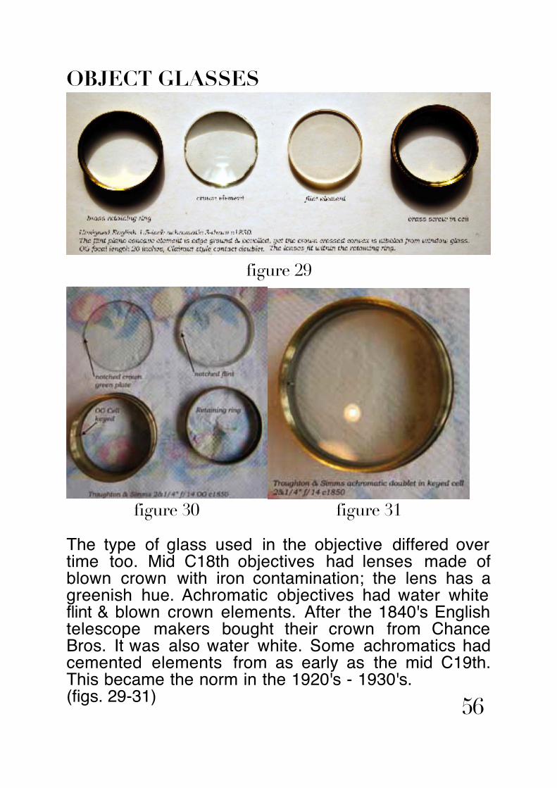
OBJECT GLASSES
figure 29
figure 30 figure 31
The type of glass used in the objective differed over time too. Mid C18th objectives had lenses made of blown crown with iron contamination; the lens has a greenish hue. Achromatic objectives had water white flint & blown crown elements. After the 1840's English telescope makers bought their crown from Chance Bros. It was also water white. Some achromatics had cemented elements from as early as the mid C19th. This became the norm in the 1920's - 1930's. (figs. 29-31) 56

EXAMPLES OF OLD REFRACTORS
figure 32Four C19th refractors, two single draw, a 2-draw & a 3-draw.Frodsham c1840 barrel length is 25&1/4", extended 38", barrel OD 2&1/2" tapering to 2&1/8". Draw OD 1".593 - 17swgJ. Cetti c1820 barrel length is 13&3/4", extended 34&1/8", barrel OD 2".45. Draw OD's 1".766 & 1".632 - 32swg, X12.5 Day, x10 NightJ. Hughes c1800 barrel length 18&1/4", extended 31&1/4", barrel OD 2".4. Draw OD 1".762 - 68thou, x13 Day, x4.5 NightBarton c1810 barrel length 10&1/8", extended 32&1/4", barrel OD 2".43. Draw OD's 1".8, 1".625, 1".456 - 23swg
57

figure 33
Dating an old brass refractor from its eyepiece arrangement is not reliable. There was a considerable transition period from Schryle 4 lens, thru’ Schryle-Huygens 4 lens & 4 lens Pancratic. (fig.32&33)
The Frodsham, Liverpool could be dated between 1835 & 1845, the dates when Henry Frodsham signed his refractors “Frodsham”. After his brothers set up their own firms, he signed his refractors “Henry Frodsham” or “H. Frodsham”.
Frodsham c1840 - OG dia. 1&15/16" x 28"fl - split drawtube with Schyrle 4 lens eyepiece (original eyepiece missing)J. Cetti c1820 - OG dia. 1&1/2" x 31&1/4"fl - 2 draw, Pancratic 4 lens eyepiece within 2nd draw.J. Hughes c1800 - OG dia 1&1/2" x 17"fl - split drawtube with Schyrle 4 lens eyepiece.Barton c1810 - OG dia. 1&1/4" missing - 3 draw with Schyrle 4 lens eyepiece within third draw.
58

figure 34a
SIGNATURES
Brass telescopes signed by the maker or retailer, (usually the maker), if hand engraved, have greater market & resale value. Later signatures were machine engraved in an uppercase font, and though helpful in dating the refractor, do not have the same appeal for collectors. Firms often had the engraving done to order.
Signatures should be checked against WEBSTER'S instrument maker's biographies. This will provide a manufacturing epoch based upon the period the business flourished. (fig.35)
Frodsham, J.Cetti, J. Hughes & Barton OG and cell arrangements and eyepiece configurations.(fig.34a&34b)
59

Frodsham, J.Cetti, J. Hughes & Barton eyepieces.figure 34b
60

SIGNATURES
figure 35 61

BRASS JOBBER’S ASSEMBLY MARKS
figure 36brass jobber's assembly marks on spring collars 62

CANNISTERS & TRUNKS
figure 37
This telescope was sold by a retailer, and judging from its similarity was made by Barton c1810. The trunk is in Royal Navy colours. (fig.37)
Unsigned 3 draw c1810 in RN blue pasteboard trunk marked "J.G." in gilt. James Gardner, London, fl 1791-1830.
63

Brass jobber’s marks were used to identify mating parts because many of the same type were made in batches, but none were interchangeable. Note should be made of jobber’s marks during dismantling prior to refurbishment or restoration. (fig.36)
MORE EXAMPLES OF OLD REFRACTORSPre-achromatic brass refractors were fitted with single element OG’s stopped down by a plate within the cell, in the example shown (fig. 38) by 58%. This was to increase the effective focal ratio, in this instance from f/19 to f/47, so as to provide the necessary LSA & LCA correction.
The 3 element Schyrle eyepiece is split into three separate cells retained within a draw section. The three sections screw into one another to form a single draw.
The barrel is turned from the branch of a fruitwood tree, probably Gage. Taper or polygonal barrels were common, more so than cylindrical barrels. It is occasionally claimed polygonal barrels prevented the refractor rolling about in a ship’s cabin, but this is a flight of fancy since the barrel ends are always cylindrical and the roll of an C18th vessell would easily overcome the rolling resistance of the barrel on a desk or table.(fig.38)
64

Single-draw pre-achromatic telescope with a taper fruitwood barrel and a Schyrle erecting system (unsigned c1740, English). The telescope has an barrel length 13&1/4", extended 21". The objective dia. 1".082 stopped down to 0".45. Each segment of the draw contains one of the three lenses of the Schyrle erecting system. Magnification x8.
UNSIGNEDSIMPLE SINGLE DRAW c1740
figure 38 65

COMPARISON of FRODSHAM & J. LILLEY & GILLIE SINGLE DRAW MARINE
66

figure 39 & 40
The one thing that stands out in terms of design is how long manufacturing practices were maintained amongst the plethora of scientific instrument makers from the mid C18th thru' mid C20th. Just to illustrate my point, take two single draw marine refractors in my collection. The Henry Frodsham, Liverpool, was made sometime between 1835 & 1845. After 1845 Henry Frodsham signed his telescopes "H. Frodsham", after his brothers Charles & John started trading in London under their own names. The J. Lilley & Gillie dates from the 1930's, and the South Shields firm is still trading. They are remarkably similar in design and construction, if not in appearance. (fig.39 & 40)
67
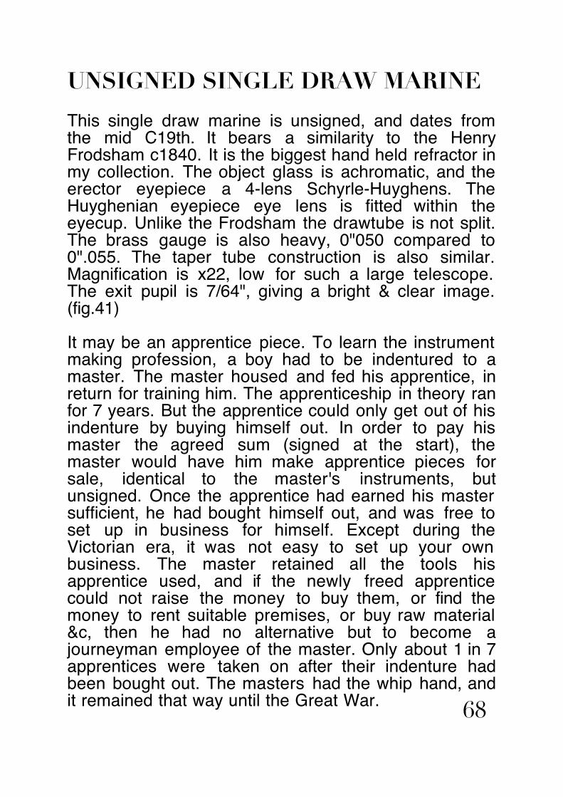
UNSIGNED SINGLE DRAW MARINE
This single draw marine is unsigned, and dates from the mid C19th. It bears a similarity to the Henry Frodsham c1840. It is the biggest hand held refractor in my collection. The object glass is achromatic, and the erector eyepiece a 4-lens Schyrle-Huyghens. The Huyghenian eyepiece eye lens is fitted within the eyecup. Unlike the Frodsham the drawtube is not split. The brass gauge is also heavy, 0"050 compared to 0".055. The taper tube construction is also similar. Magnification is x22, low for such a large telescope. The exit pupil is 7/64", giving a bright & clear image. (fig.41)
It may be an apprentice piece. To learn the instrument making profession, a boy had to be indentured to a master. The master housed and fed his apprentice, in return for training him. The apprenticeship in theory ran for 7 years. But the apprentice could only get out of his indenture by buying himself out. In order to pay his master the agreed sum (signed at the start), the master would have him make apprentice pieces for sale, identical to the master's instruments, but unsigned. Once the apprentice had earned his master sufficient, he had bought himself out, and was free to set up in business for himself. Except during the Victorian era, it was not easy to set up your own business. The master retained all the tools his apprentice used, and if the newly freed apprentice could not raise the money to buy them, or find the money to rent suitable premises, or buy raw material &c, then he had no alternative but to become a journeyman employee of the master. Only about 1 in 7 apprentices were taken on after their indenture had been bought out. The masters had the whip hand, and it remained that way until the Great War. 68

figure 41
69

SIGNALLING & POCKET REFRACTORS
figure 42
70

figure 43 71

OFFICER of the WATCH TELESCOPE
figure 44
'Officer of the Watch' telescope, T. Cooke & Sons Ltd., London & York No.2214 c1915. Single-draw air-spaced contact achromatic telescope leather bound barrel and a Pancratic erecting system. The telescope has a barrel length 17&3/8", extended 24&7/8". The objective dia. 1&1/4". Nickel plated brass. Magnification x10.
72

'Officer of the Watch' telescopes were worn by officers of the Royal Navy as part of their ceremonial dress uniform. Each officer was expected to buy his own telescope, and most marine instrument makers supplied them to a standard design, hence the 'Earl of Sandwich's' arrow, & unique supply identification number. The abraded upper section of the barrel would be where the officer had fastened a platted lanyard. (fig.44)
For further examples of Officer of the Watch telescopes see Appendix -3, OoW. pp132-219.
73

TABLE TOP REFRACTORS
figure 45
Table top 2-inch terrestrial refractor with Schyrle 4-lens eyepiece made by Henry Husbands, 8, Augustine's Parade, Bristol c1870. The brass barrel length is 20", extended 32.5", the drawtube OD 0".96. The OG clear aperture is 1".972.
Husbands signature on rack & pinion body.figure 46
74

figure 47
Henry Husbands and William Clarke had a scientific instrument making shop in Bristol, as partners between 1858 & 1870, following which Husbands operated the business alone and subsequently with his sons until he died in 1900. Three of Henry's sons maintained the Husbands & Sons' shop until 1910.
Henry Husbands table top, pillar & claw stand of iron, restored bronze gilding to claw legs and trunnion.
75

The business was the main supplier of instruments in Bristol in the latter half of the C19th. The shop still stands today, on the corner of Augustine's Parade & Denmark Street.
figure 48
76

77

HUSBANDS ACHROMATIC SINGLE DRAW c1870
78

figures 49,50,51
Schryle 4-lens eyepiece in three sections - note copper joint along the length of the centre section
79

figures 52 & 53
Unsigned 2 draw table top c1850-1900

figure 54
figure 55Troughton & Simms table top refractor c1850.
81

figure 56
figure 57
Troughton & Simms Trade Card c1850 underneath Henry Husbands Trade Card. Rackmount repaired and rack flange engraved Husbands & Sons, trade card signed S/H 3rd/X/70 £15, meaning it was repaired and resold on October 3rd. 1870. (figs. 56, 57, 58)
Unsigned 2 draw table top c1850-1900
82

figure 58
figure 59
Compare the signature on a Troughton & Simms hand held refractor to a table top (figs. 59 & 55). The former is hand engraved whereas the latter is machine engraved.
5
83

ASTRONOMICAL REFRACTORS
figure 603-inch f/12 unsigned achromatic refractor, intended for both terrestrial and astronomical use. The barrel is red brass (62-38) c1880, and has 'season cracking'. The eyepiece is a Broadhurst, Clarkson & Co., Ltd., Pancratic c1910, RAS screw fitting. The original object glass which would have been very similar to a spare B.C. & Co.,Ltd., 3" f/13 achromatic doublet in my collection, dating from the 1910's, has been replaced with a Conrady design achromatic triplet c1960. (fig.60)
84

figure 61 85

TULLEY & SONS 5-FOOT ACHROMATIC
This undocumented Tulley is a very early example of an English telescope maker mounting an astronomical achromatic refractor on a German style Equatorial. The mount design is taken from the existing Dollond altazimuthal, Smeaton's block & the Tulley universal equatorial, and retains features from both, with wormwheels close to the cg, and the Declination wormwheel in line with the polar axis. It maybe a German style equatorial, but it is an English interpretation and execution. Fraunhofer's equatorial had wormwheels at the ends of each axle. Unlike Tulley's universal equatorial in which the elevation of the polar axis can be adjusted to the observer's latitude, the polar axis of this mounting is fixed at 51º.5, the latitude of London, and maybe a prototype. (fig.61)
figure 62
figure 63
Tulley 3.8-inch f/16 achromatic doubletc1830. (fig.63)
Note the similarity of the machine engraved signature to the Troughton & Simms table top. (figs.55 &62)
86

figure 64
Whereas hand held and table top refractors are highly collectable, one has to exercise caution with regards to the collectability of old astronomical refractors. Observatory class antique refractors are most definitely not collectable, indeed most are white elephants. Some astronomical refractors though are prized amongst collectors because they represent landmarks in technological development.
An astronomical telescope on a portable stand, that can be displayed in the hallway or study, which has an interesting provenance is a worthwhile investment providing you don’t pay over the odds to acquire it.
Provenance is always a bonus, but of almost equal importance is state of preservation. Astronomical refractors by their very nature tend to have had a hard
87
life, even more so than bashed about naval refractors. It is inadvisable to buy an old astronomical refractor without having examined it closely. The stand may not be genuine, but reproduction. The telescope may have had a new case made for it. The OG may have been replaced, either with another old OG from a similar ‘scope or a modern OG.
Well known English makers, such as Troughton & Simms, Thomas Cooke, Alexander Clarkson (not B.C. & Co.), Wray, Watson, Steward, Ottway &c fetch a high price at scientific instrument auctions. They are undoubtedly collectable but not a good investment. The place to find prize specimens is at provincial and country auctions.
If you venture down this route I recommend you do your homework. You are best advised to brush up on C19th/early C20th astronomical refractor history, the firms, their catalogues and products, and recent major auction house prices.
Astronomical refractors differ optically from hand held refractors, in that the latter usually have a fixed 3, 4 or 5 element wide air-spaced eyepiece with an image erector stage. They are intended to provide a fixed magnification and an upright image. The aberrations of the OG & eyepiece-erector are balanced, particularly if the OG is a single element.
Astronomical refractors are a different animal altogether. The OG is designed as a stand alone optic, whose aberrations have been minimised. Astronomical eyepieces are interchangable. The maker will have supplied the refractor with a range of eyepieces having powers varying from low power thru’ to very high. The drawtube will have either an RAS screw thread (1.25-inch x 16TPI WHITWORTH), 88

or a non-standard push fit. Each maker had his own eyepiece fitting to discourage the amateur astronomer buying eyepieces and accessories from rival firms.
The RAS standard screw thread was introduced in the late 1840’s by the Royal Astronomical Society, based on Dollond’s biggest eyepieces. It remained standard in England from the latter quarter of the Victorian era right through until the 1960’s when it gradually gave way to the American 1.25-inch push fit.
I have a set of brass Ottway eyepieces made in the 1950’s for the US market, that have the RAS fitting but over which have been fastened 1.25-inch brass sleeves, by Ottway themselves.
Astronomical refractor eyepieces also have eyecup filter threads or a push fit collar, to accept colour screens. The screw thread or collar size differs slightly between makers. Again a deliberate attempt to restrict the buyer to the original firm.
Colour screens are filters that fit over the eye lens. The Sun screen filter is potentially dangerous. Often the glass is split because of the concentrated heat of focused sunlight.
The safest way to look at the Sun through an old refractor is solar projection using a Huygenian eyepiece. The telescope is used as a projector, and the image is focused on a white card held a foot or so away from the eyepiece.
Another, better way, requires a Herschel Wedge. This is a specially shaped prism, that allows most of the solar flux to escape, and only 4% or so is reflected into the eyepiece. The Sun screen filter can then be used safely. (appendix-1 & 2) 89

Watson’s & Clarkson’s supplied a combined Sun & Star diagonal. B.C & Co, in the C20th made a copy of it, which is not so collectable, later B.C&Co. Sun diagonals have Duralumin end caps painted black.
Astronomical refractors have a smaller field of view (fov) than hand held refractors. Pointing the telescope at a celestial object is difficult, and an essential accessory is a small “Finder” telescope mounted alongside the main tube near the eyepiece. The finder ‘scope is a low power refractor, usually but not always achromatic, fitted with a Ramsden or other postive eyepiece, with cross wires. The finder ‘scope’s tube is mounted off the main tube with finder rings, fitted with collimation screws. It has to be collimated with the main tube, so when an object is seen in the finder’s wider fov and centred on the cross wires, it is in the field of the main ‘scope.
Old astronomical refractors have an internal rack & pinion focuser. The rack should be checked for smooth motion. The rack tube has a rack fastened to it, and the pinion is mounted on a saddle plate on the end of the tube, fitted with a pinion wheel, or focusing knob. Within the racktube is the eyepiece drawtube. If it is badly tarnished it will be too tight a fit. One thing to always look out for is a stripped rack caused by ramming the eyepiece drawtube home before winding in the racktube. Repairing or replacing a stripped rack, or a damaged rack, is expensive even if you can find someone able to do the job. Best to avoid such instruments.
The eyepiece drawtube is so designed as to accept a Barlow lens. The Barlow lens, named after it’s inventor, Peter Barlow, of Woolwich Arsenal, in 1832, is an achromatic doublet with a negative focal length. It is mounted in a brass tube that can be slid into 90

the eyepiece drawtube. It increases the effective focal length of the OG by up to 3 times, depending on the separation of the Barlow and eyepiece.
A Barlow lens is a very useful accessory because it has the effect of throwing the focal plane further out, enabling a star or sun diagonal to be used, and still be able to focus the image.
figure 65
Formulae for the Barlow lens:
€
S = B A −1( )
A =Sd
A =SB
+1
1B
=1d−1S
B = S ×dS − d
where S = Barlow - eyepiece separationd = Barlow to original focal plane distanceB = Barlow negative focal lengthA = Amplification
91

Usually the Barlow focal length is known, at least it would have been at the time of purchase from the maker. However when you, the collector, come across it in the telescope case, or within the drawtube, you will not know what focal length it is, and you will have to work it out for your self.
This is a simple matter. Mark the drawtube where the image is in focus without the Barlow. Insert the Barlow 4 inches in front of the eyepiece, focus the image and mark the drawtube again. The distance between the lines is
€
S − d . Let’s say for example
€
S − d = 2 inches. We know S = 4 inches, so we know
€
d = 4 − 2 = 2 inches, and from:
€
B =S ×dS − d
Barlow focal length:
€
B =4 ×24 −2
=82
= 4 inches
The focal length is always negative, but the algebraic sign is ignored in the formula.
The amplification is then determined by simply dividing
€
S by
€
d , in this instance
€
A = ×2. In other words, by inserting a -4 inch Barlow lens 4 inches in front of the eyepiece, the OG effective focal length is doubled and consequently the magnification will be doubled, but the focal plane is only thrown out 2 inches.
Most English astronomical refractor makers made achromatic Barlows from the mid C19th until the 1960’s having focal lengths either -4 or -8 inches. Unfortunately the Barlow would be made to only fit the maker’s drawtube. They are not interchangeable across different makes. The sole exception was Ronald Norman Irving of H.N. Irving & Sons, fl1947-2005. I have a classic alt-az 4-inch f/15 refractor of his and the drawtube is interchangable with that in my 3.8-inch f/16 Tulley, made 160 years earlier! 92

TYPES OF STAND
Astronomical refractors, being high power telescopes cannot be hand held. Any refractor larger than 2-inches aperture requires a stand to obtain a steady image.
Some astronomical refractors in the aperture range 2 to 3 inches were intended for both astronomical and terrestrial use. However a pillar & claw table top stand will not afford views of celestial objects near the zenith. Which is why an astronomical telescope in the aperture range 3 to 4 inches was supplied with a heavy duty tripod. The head was usually altazimuthal (alt-az), enabling motions in the horizontal and vertical planes.
Of more use for tracking celectial objects was an equatorial mount, enabling motions in the planes of Declination and Polar distance. Equatorial mounts have perpendicular axes just like an alt-az, but the vertical axis of the alt-az is tilted over to the site latitude and directed to the north celestial pole. Once a celestial object is centred, the telescope can be made to follow it’s diurnal motion by simply moving it about it’s polar axis. Once set, there is no need to adjust the Declination. This means any celestial object can be tracked using only a single slow motion. More advanced equatorials were fitted with clock drives, enabling the celestial object to be tracked continually with no input from the observer, who was then free to concentrate on the object itself, which remained in the field of view at all times.
Slow motions were provided by worm and wheel drives, controlled by rods and Hooke’s joints. The rods hang down near the eyepiece end, for convenience. Some pillar and claw stands have either an altitude rod with a rack & pinion motion, or both an altitude rodand an azimuthal slow motion worm and wheel 93

drive at the bottom end of the pilar.
Celestial objects have co-ordinates that may be found in an astronomical almanac. The co-ordinates are in Right Ascension and Declination. Advanced equatorial mounts are fitted with setting circles, Declination and Hour Angle. These are used to point the telescope from the object’s co-ordinates. Hour Angle is the Local Sidereal Time (LST) minus the Right Ascension (RA). Some Hour Angle setting circles have two sets of pointers, one for the RA and the other LST. LST is either calculated from GMT, (or UT), or obtained from a sidereal clock.
Astronomical refractors larger than 4-inches aperture, be they on alt-az garden stands, or equatorials, are too heavy to be portable. They may perform admirably as the desired telescope of a budding amateur astronomer, but they have limited appeal in the antiques trade. They also take up a lot of space, and ideally require an observatory. It is for this reason I personally do not regard them as collectable. A large astronomical refractor in serviceable and restorable condition will cost a lot of money, and when (if) you decide to sell it, you will be hard pressed to find a buyer.
PILLAR & CLAW STANDSPillar & Claw stands were intended for desk or table top use. Patrick Moore was fond of reiterating that a Pillar & Claw stand was as steady as a blancmange. What he clearly failed to appreciate is that they are entirely unsuited to an astronomical refractor. Pillar & Claw stands were never intended for observing objects at more than about 40º elevation.
94

figure 66 & 67
A Pillar & Claw stand is perfectly stable when the cabriolé leg hinge pins are properly tightened up, and the tripod feet are placed on a stable, hard, flat, level surface. If the brass pillar is hollow I add weight by filling it with lead shot. The extra weight lowers the centre of gravity and increases stability.
The cabriolé legs were either made of brass, lacquered to match the pillar and telescope, or iron. The iron work was normally bronzed with a patiniser, but occasionally it was gilded. The style of leg and the taper of the pillar varied with instrument maker, and evolved over 150 years or so from ornate toplain. Likewise the design of the feet. The pillar
Ramsden, late C18th (fig.66) & Matthew Berge, London, early C19th (fig.67) - pillar & claw with pad feet & altitude adjustment.Matthew Berge apprenticed to Jesse Ramsden, his father or uncle, John Berge apprenticed to Peter Dollond.
95

could be removed from the legs, and fitted to either a field tripod, or if there was a forged coach screw protruding from the base, into a fence post.
figures 68 & 69
Husbands - claw legs - inverted & hinge boss - note centre punch marks used to assemble each leg & hinge pin correctly.(figs.68 & 69)Note also traces of lead chromate primer applied before the bronze gilding which had been rubbed off. New brass hinge pins were turned to suit, blackened with Selenium compound, and the cabriolé legs and hinge boss re-primed with lead chromate and gilded dark bronze. (fig.47)
96
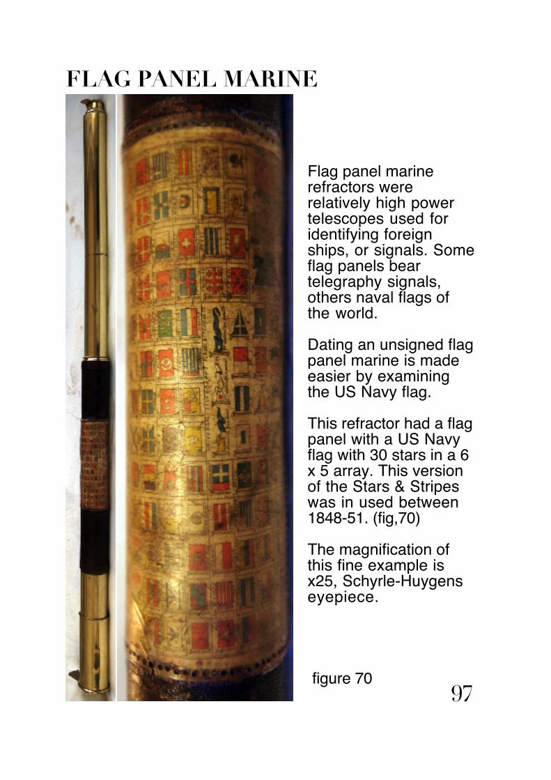
FLAG PANEL MARINE
Flag panel marine refractors were relatively high power telescopes used for identifying foreign ships, or signals. Some flag panels bear telegraphy signals, others naval flags of the world.
Dating an unsigned flag panel marine is made easier by examining the US Navy flag.
This refractor had a flag panel with a US Navy flag with 30 stars in a 6 x 5 array. This version of the Stars & Stripes was in used between 1848-51. (fig,70)
The magnification of this fine example is x25, Schyrle-Huygens eyepiece.
figure 7097

BUYING ANTIQUE & VINTAGE BRASS REFRACTORS
When I started collecting antique refractors in the mid-late 1960's they could be found in junk shops for under a fiver. The most I ever paid was £17. Junk shops became 'antique' shops, and the fancy name for what was in essence the same old junk shop, only with airs and graces, charged more, and pushed up prices, but not necessarily value. Throughout the 1970's and early 80's the price of antique refractors remained flat, and even fell against inflation, which was then in the region of 20%. Vintage refractors fell in value. This situation changed dramatically in the late 1990's, and the price commanded at auction by the better names, such as Dollond, Ramsden & Adams, are now truly astronomical. Given the current low interest rate on banking investments or bonds, buying antique brass refractors with a view to selling them on in a decade or so, is a sound investment.
So where do you go, and what do you look for? Websites such as 'Fleaglass', and 'Antique & Scientific Instruments' & 'Scientific Collectables', offer fixed prices from private sellers or dealers. Dealers such as Russell, Philips, or local dealers such as Graham Marsh (Tockholes, Darwen, Lancashire), buy, sell & repair antique refractors. Auctioneers such as Bonhams, Philips, Christies, specialise in rare and fine antique refractors, requiring no restoration. The trading site eBayUK offers antique and vintage refractors either by auction, or at a fixed price. The way to make money in the long run, is to bid on refractors requiring some restoration; eBayUK 'Buy it Now' (BIN) listings will rarely provide a return even over ten years. I have followed numerous table top refractors on pillar &claw stands, listed as BIN, which have been 98

rolled over for years, and still not found a buyer.
If you use eBayUK, look at not only <telescopes> or <antique telescopes> but also <scientific instruments> <military memorabilia> & <marine memorabilia>. Draw up a watch list and follow the bidding to get a feel for what certain types of refractor make. This provides a yardstick when bidding, so you are not tempted to overbid. When a choice refractor is listed, check out the fixed price and other auction sites to see what a similar refractor sold for, in order to gauge its worth. An antique refractor is only worth what a buyer is willing to pay, but if you pay too much, you may not get a return on your investment. You need to have a figure in mind when you start bidding. If the bidding goes beyond your guestimate, let it go, don't be lured into a bidding frenzy.
Just remember, the best return is to be had on unusual listings in obscure places, listed by a seller who hasn't a clue what it is they are selling (yes it does happen!). Add the listing to your watch list and enter a low bid to keep it near or at the top. Decide the most you're prepared to pay, and match rival bidders to the close. Some bidders, especially private collectors, use auto-bidding software to place a high bid at the final second. The way around this is to put in your highest maximum bid in the last minute or so. If the rival bid is less, you win at a nominal increment above the rival bid, rather than your maximum, and if the rival bid exceeds your maximum, well that was the most you were prepared to pay anyway, so forget it, and move onto the next on your watch list.
One final word, please don't be fooled into buying a dreadful Indian replica. They maybe cheap, but if something looks too good to be true it inevitably
99

is too good to be true. They may look like the real thing to the untutored eye, but they're awful; poorly designed, badly made, and most certainly not an investment. If you want a useful guide to authentic firms I can do better than refer you to Webster's Instrument Makers Database.
100

CLEANING, RENOVATION & MAINTENANCE of ANTIQUE & VINTAGE BRASS REFRACTORS
Renovating antique and vintage refractors is not difficult. All it takes is a good deal of elbow grease, and some mechanical engineering nouse.
The first task is to completely dismantle the telescope. Usually this is simply a matter of unscrewing the objective cell, splash shield and objective cover slide, if it has one; the drawtube retaining collars; withdrawing the drawtubes; unscrewing the erector and eyepiece tubes, and then unscrewing the lens cells. It is important to make a note of which lens cell screws into which end of which tube; a sketch proves invaluable. I make notes of the lens focal lengths and separations when a distant image is in sharp focus; the type of erector, i.e. whether it is a Schyrlean or Pancratic, and use the figures to calculate the power. A fob watch spherometer is a handy tool for determining lens focal lengths, otherwise project an image onto a white card on a sunny day, and measure the distance using a rule. Drawtubes and erector & eyepiece tubes &/or cells sometimes have jobber's marks scratched into them, that aid re-assembly. (fig.36)
Occasionally a cell or a collar is jammed. A handy pair of tools to try to force it to turn is either a jar lid opener, or a tape pipe wrench. If a spring retaining collar won't budge, soak the drawtube and it in paraffin overnight and try again. If it is still jammed try applying a modicum of local heat with a blow lamp, but don't get it too hot or the soldered flange on the spring retaining collar may come apart. Plunging the hot collar end into cold water is usually enough to make the thread unlock. 101

Sometimes threads are crossed. Nothing else for it but to force them apart and run a chaser down each thread to get rid of the burrs. Use a little #5 block grease applied to each thread when reassembling. The way to avoid crossing threads on reassembly is to turn the threaded part backwards (anticlockwise), keeping the gap even all round, until you feel a click where the thread starts. You can now turn it clockwise and if the thead hasn't crossed, there ought to be little resistance.
If the objective or any of the erector or eyepiece cells are jammed, you need to exercise care if using a lid opener. Sometimes it is best to leave well alone and work around the problem. Lenses usually require cleaning, but you don't necessarily have to unscrew the cell to gain access to either side. Lenses should be cleaned with a proprietary liquid lens cleaner, applied with a soft tissue or chamois cloth. Don't apply the liquid to the lens. Brush dust and dirt off first, and then apply the liquid to the tissue or cloth, and polish the lens that way. The objective can usually be removed from its cell for cleaning. Make a note of any edge marks, and ensure you note which way the elements face. Erector and eyepiece lenses tend to be spun into their respective cells, so cannot be removed. If a lens is loose within its spun cell, run around the lip with a polished round bar to peen it back over.
Once you have the refractor completely dismantled, you need to set about removing the tarnish and/or oxidation from the brass work. For this you need a set of emery paper grades from 240 thru' 3000. 'Axminster Tools' is a handy supplier of A4 emery paper packs, as is 'Alec Tiranti', 'Joseph Cornellian', and 'Meadows and Passmore'. You also need a Brasso rag, an old heavy dish cloth is most suitable, a buffing rag, and a polishing cloth. Also 'PreLim' brass polish 102

and 'Renaissance Wax'. Polishing tools comprise a piece of old kitchen worktop, veneered on one side only, wooden dowels ranging from 1/8" thru' 1/2" diameter, emery impregnated buffing blocks, Selenium black copper & Haematite iron patinator, Shellac lacquer in various shades of yellow ranging from pale yellow through gold to deep bronze, lacquer brushes, Shellac varnish, fine steel wool, and Duraglit.
Drawtubes are polished using each grade of emery paper, dry, starting with 240 if the oxidation is heavy, or 400 if light. Each grade is used for as long as it takes to polish out the sleeks from the previous grade. I always use whole A4 sheets (or A5), and rub along the length of the tubes. The grades run from 240; 400; 600; 800; 1000; 1200; 1500; 2000; 2500; 3000. By the time you get to 3000 grade your hands will be green, and the brass tube polished to a mirror finish. The tube is then polished against a flat cloth on the old piece of kitchen worktop, rough side up. Lay the cloth on the board flat down and pour on a little Brasso. Rub the tube over the polishing cloth holding it at either end, moving the tube to and fro at right angles to its length, steadily rotating it until you have completed three rotations. Move the tube to an area of the cloth that as no Brasso on it, to clean off the black residue, using the same motion. Then buff the tube longitudinally with the buffing rag. At this stage the tube should look pristine, without a sleek or a blemish, other than the odd dent. Next use a paper towel to apply PreLim, rubbing up and down the length of the tube. Buff off with a clean sheet of paper towel, and then rub down with Renaissance Wax.
The spring retaining collars need to have their flange faces and knurling buffed up and polished. Don't try to polish the springs or the screw threads.
103

The OG cell may require buffing. I use a kebab stick wrapped with a strip of emery paper to get into the profiling, and then finish off on the Brasso cloth using the edge of the board as a guide. Same applies to the eyecap.
The dustcap, or cover slide, spring collars, and eyecap need relacquering. Wash these polished parts in warm soapy water, and then thoroughly dry off using kitchen towel, and then place in a tepid oven on a baking tray to drive off any moisture. The lacquer has to be applied with a suitable brush, either Squirrel, Zorino, or Camel hair, so as not to leave brush marks. You only get one shot at this, so practice on a plain polished sheet first. The trick is not to go over what you've already painted, because the shade deepens where you do so. If you mess up, which if its the first time is very likely, wash off the lacquer with Methylated spirit, dry in a tepid oven, and have another go. The easier alternative is to use nitro-cellulose lacquer, coloured with Irgalite dyes. Irgalite is a photo-stable dye. (fig.71)
The shade you require depends on the age of the refractor. Mid C18th thru' late C18th refractors have a pale gold almost lemon lacquer because of the red brass used. Early to mid C19th have a mid gold lacquer, and late C19th thru' early C20th a deep gold almost orange lacquer, because of the switch to Muntz brass, 60-40 composition.
Larger terrestrial or astronomical refractors usually have brass barrels, sometimes bearing the maker's signature. You have to do your best to avoid abrading the signature. This can prove a problem if the barrel has pitting corrosion. One of the principal causes of pitting corrosion is dew contaminated by nitrous, sulphurous or carbonic acid. The tell tale sign is pitting on the uppermost side of the tube, and little or 104

figure 71
none underneath. Soot or dirt particles on the tube act as nucleation points for condensates. The weak acid acts as an electrolyte producing galvanic action between the face centred cubic zinc and copper crystals in the brass alloy. The localised area becomes anodic, and the surrounding area cathodic. Zinc and the copper ions react at different rates, producing either copper carbonate, sulphate or nitrate, around the nucleation point (examination of a pit with an eye loupe in a bright light will reveal the acid responsible; copper carbonate is greenish, copper sulphate
Five shades of Iragalite dyed nitro-cellulose lacquers.
105

bluish, and copper nitrate dark brown). Pitting is the most insidious type of corrosion, and dealing with it is problematic. Whichever renovation method you choose, none is ideal. If you are able, better to ignore it, and prevent further pitting by keeping the tube protected with Renaissance Wax.
Sometimes the pitting corrosion has only effected the lacquer coating and the outermost brass surface, being so shallow that vigorous buffing with a Brasso soaked paper towel will polish off both the lacquer and the black pits. It doesn't take long to discover if the corrosion is deeper. Count yourself fortunate if this is all it takes.
If the pitting is fairly shallow a technique I use is to clean the tube external surface with white spirit or turpentine substitute to remove any grease. I then bathe the external surface in hot soapy water, and dry it thoroughly, taking care not to get water inside the tube. The signature is then covered with gaffer tape, and the usual polishing process gone through, until a mirror finish, free of sleeks, is obtained. The gaffer tape is then removed, and local retouching applied to each of the remaining pits. This is a tedious, protracted process, but well worth it. Be prepared to spend days re-polishing. Start with a fairly fine grade, such as 600 or 800. Finish with PreLim (use Brasso if you must but rinse afterwards). Treating the restored surface with Renaissance Wax, applied monthly, prevents further pitting corrosion.
Deep pitting has to be left because resurfacing would remove too much material. It is better to treat each pit with a weak alkali solution such as diluted bleach, applied with a cotton bud, and rinsing in warm water afterwards. If you try to polish the pits out all you will succeed in doing is emphasising them. 106
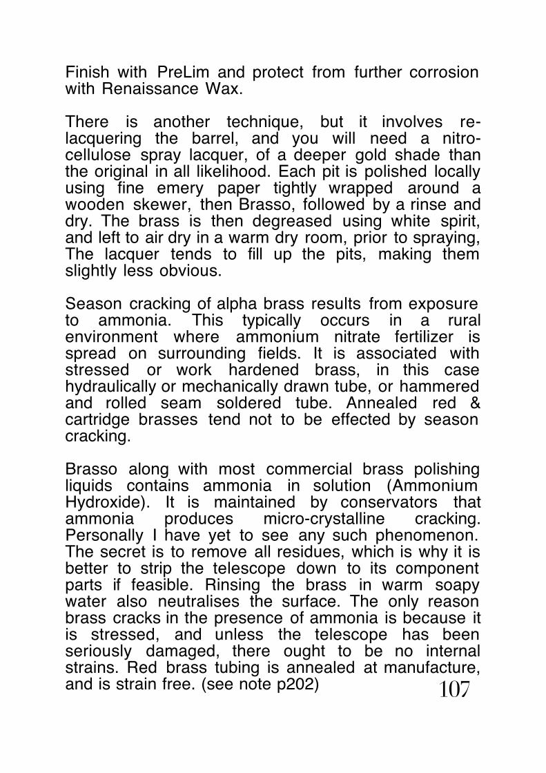
Finish with PreLim and protect from further corrosion with Renaissance Wax.
There is another technique, but it involves re-lacquering the barrel, and you will need a nitro-cellulose spray lacquer, of a deeper gold shade than the original in all likelihood. Each pit is polished locally using fine emery paper tightly wrapped around a wooden skewer, then Brasso, followed by a rinse and dry. The brass is then degreased using white spirit, and left to air dry in a warm dry room, prior to spraying, The lacquer tends to fill up the pits, making them slightly less obvious.
Season cracking of alpha brass results from exposure to ammonia. This typically occurs in a rural environment where ammonium nitrate fertilizer is spread on surrounding fields. It is associated with stressed or work hardened brass, in this case hydraulically or mechanically drawn tube, or hammered and rolled seam soldered tube. Annealed red & cartridge brasses tend not to be effected by season cracking.
Brasso along with most commercial brass polishing liquids contains ammonia in solution (Ammonium Hydroxide). It is maintained by conservators that ammonia produces micro-crystalline cracking. Personally I have yet to see any such phenomenon. The secret is to remove all residues, which is why it is better to strip the telescope down to its component parts if feasible. Rinsing the brass in warm soapy water also neutralises the surface. The only reason brass cracks in the presence of ammonia is because it is stressed, and unless the telescope has been seriously damaged, there ought to be no internal strains. Red brass tubing is annealed at manufacture, and is strain free. (see note p202) 107

EXAMPLE OF BEFORE & AFTER CLEANING & RENOVATION
figure 72
figure 73Troughton & Simms table top - cased.
Troughton & Simms, London, c1850 - 2-inch table top, pillar & claw braced stand.Note the upper part of the brass barrel has pitting corrosion.
108

Troughton & Simms table top - cased - repolished
figure 74Troughton & Simms on braced pillar & claw stand. The barrel has pitting corrosion to the uppermost part only, caused by dew contaminated with either agricultural or industrial atmospheric pollutants.
figure 75
109

Note the pitting corrosion is absent from the underside of the barrel - this is indicative of dew contaminated with either nitrous, sulphurous or carbonic acid, from either a damp rural, or industrial atmosphere. The lengthways split in the Cuban mahogany case lid is caused by storage at low humidity. The simplest way to repair it, is to leave the empty case in a damp shed, and once the wood expands, infill the split with Cascamite or Hide wood glue. (figs.72. 73 & 74)
figure 76
figure 77 110

Troughton & Simms signature, after re-polishing (fig.76). The engraving technique, known as machine copying, was used at their 138 Fleet Street factory. Compare the condition of the brasswork with that prior to renovation (fig.72). The shallow pits left on the surface have been polished out. Renaissance Wax prevents the pitting corrosion getting any worse, and re-lacquering will fill in the shallow depressions, leaving them imperceptible.
The barrel has been re-polished with Brasso and a rough cloth to remove the lacquer, and paper towel to remove all traces of pitting corrosion, then finished with conservator's polish PreLim and Renaissance Wax. (fig.77)
CLEANING, RENOVATION & MAINTENANCE of ANTIQUE & VINTAGE BRASS REFRACTORS (cont.)
Mahogany or fruitwood barrels, if they are cracked, can be glued using hide wood glue, and wrapped with masking tape whilst the glue sets. The tube can then be re-polished using fine steel wool, or a buffing block, until you obtain a mirror finish, and then varnished with a rag soaked in shellac made from waxed flakes, sometimes referred to as button polish.
Leather bound barrels, where the stitching is intact, should be cleaned with Saddle Soap, then primed with Dubbin, before being polished with the correct shade of wax shoe polish. If the stitching is damaged and the leather has shrunk back you are faced with two choices. If it is beyond repair, remove the leatherand either buy a similar piece in the same or a 111

near shade, and stitch it yourself, or simply polish up the brass tube beneath, and discard the leather covering altogether.
Late C19th and C20th signalling telescopes have leather bound barrels and a leather sleeve case and shoulder strap. Treat the leather with Saddle Soap, & Dubbin. Keep the leather supple by applying Dubbin every few months, especially if the telescope is kept in a centrally heated house.
Re-assemble the refractor starting with the first draw, proceeding through the second, third &c draws, ensuring you don't cross the screw threads. Then the eycap, the OG cell and glare shield, and OG cover slide. Try the draws to see if they slide smoothly, yet do not slop about. If a drawtube is a slack fit, unscrew the spring collar, and gently push in the spring tabs a little. Later refractors were fitted with felt lined spring collars, that occasionally get grit embedded. Feel the inside of the felt with you finger tip, and tease out any grit with a cocktail stick.
Once re-assembled extend the draws, and apply a modicum of Renaissance Wax to the drawtubes. Renaissance Wax is a Cosmoloid wax that protects the brass from tarnishing, and also helps the tubes slide smoothly. Reapply every few months.
Some antique and vintage refractors have plated or chemically patinated brasswork, either nickel, silver or gold plated, or blued or bronzed. Obviously the plating or coating was applied by the maker and ought to be retained. Gun bluing can be applied to damaged or worn patina, and silver or gold gilt applied to damaged or worn plated brasswork. Suppliers of gilding liquids are 'Alec Tiranti' or 'Joseph Cornellian' or 'Meadows & Passmore'. Suppliers of gun blue too 112

numerous to mention. Use cold bluing applied with a clean dry cloth.
NOTES on BRITISH INSTRUMENT MAKERS
Out of preference I only collect antique telescopes made by British instrument makers, especially English, because I find it involves less time and effort researching their histories. On-line research only takes you so far, most local information about particular instrument makers has not been digitised and probably never will be. One is obliged to ferret out articles and obituary notices in reference libraries, and the national archive at Kew.
The leading English instrument makers of the C18th & C19th, The Dollonds, Benjamin Martin, Ramsden, Cary, Adams, Jones, Harris, Berge, the Watkins’, the Tulleys’, Aitchison, Browning, Clarkson, Watson, Thomas Cooke, W. Ottway, Horne & Thornthwaite, Negretti & Zambra, J.H. Steward, and the most famous of all, Troughton & Simms, have well documented and researched histories. Lesser known makers such as J. Ceti, H.Hughes, Spencer, Browning & Rust, Henry Husbands of Bristol, require further delving, as do John Dancer, Joseph Casartelli & William Aaronsberg of Manchester & Henry Frodsham of Liverpool. C20th telescope makers, Broadhurst, Clarkson & Co., Ltd., Hilger & Watts, & Ross, also have well documented histories. One of the delights in collecting antique telescopes is coming across a lesser known make, and doing a little research about the maker.
Useful directories of British instrument makers are Webster's "Instrument Maker's Biographies" which is a free on-line data base. Gloria Clifton's "Directory of British Scientific Instrument Makers,
113

1550-1851" which is ridiculously expensive at ~£150, & Mary Holbrook's "Science Preserved, a directory of scientific instruments in collections in the United Kingdom and Eire" 1992, & "Making Scientific Instruments in the Industrial Revolution" by A.D. Morrison-Low, 2007, which covers the period 1700-1945, but is also expensive at ~£70.
USEFUL REFERENCE WORKS
There are scant few worthwhile textbooks on this subject. Reginald Cheetham's "Old Telescopes", 1997, had a limited print run and is rare. Peter Hunt's "Collecting Old Telescopes", a recent publication, being an assemblage of advertisements published between 1900 & 1960. Gerard L'E Turner's "Antique Scientific Instruments" BLANDFORD PRESS, 1980, is an adequate reference work, & there is a small Science Museum illustrated booklet on Astronomical Telescopes by A.G. Thoday, 1971. "Collecting and Restoring Scientific Instruments" by Ronald Pearsall, Arco Publishing, 1974, is the only publication dedicated to this hobby.
In my opinion Ronald Pearsall's book is the only one available, although out-of-print, which is worth having. I'd like to quote you what he has to say on the subject of cleaning and renovation, because it is clearly apposite.
"COLLECTING AND RESTORING SCIENTIFIC INSTRUMENTS" 1974
'CLEANING AND RENOVATION OF SCIENTIFIC INSTRUMENTS'CHAPTER 14 p182 114

It is still not unusual to find the more out of the way scientific instruments tucked away in the corners of junk shops, the owners of which have no idea what the objects are, and although this is not true of instantly recognisable things such as telescopes and microscopes, even these can be found in a sorry state. The collector on finding an instrument in need of a good refurbishing will have a choice of whether to bring the instrument up into tip-top condition, with gleaming brass and immaculate woodwork, or to merely remove the dirt, grease and rust and have an interesting objet d'art rather than a working instrument. Some collectors even think there is something vulgar about shining brass.
The author cannot share these delusions. A beautiful object should be presented at its best, whether it is a picture, a piece of furniture, or an instrument. Scientific instruments, unless one has an exceptionally deep pocket, are unlikely to qualify as objects where the main attraction is age, as in old oak, where the machinations of long-dead woodworm and the inroads of the occasional death-watch beetle add to the aesthetic appeal.
A scientific instrument can be divided into a maximum of four parts: (a) the metalwork, (b) the woodwork, (c) the optics (if any), (d) the covering (if any). By covering is meant the parchment, leather, shagreen, etc., used to cover the tubes of microscopes and telescopes.
The metal will more often than not be brass, and brass is very responsive to attention. If the metalwork on a scientific instrument is in a bad way, covered with grime, grease and a generation of dirt, one should not have any preconceived ideas on what it should eventually look like. In the early nineteenth century workers in brass preferred the red brasses, as 115

they were easier to work, but with the patented method of Muntz brasses became much yellower. Muntz metal, or yellow metal as it is often called, should be treated as brass.
Pearsall's approach to the restoration of antique telescopes is similar to mine. A school has arisen that equates a distressed state with "history." In the case of antique telescopes & microscopes, there is no direct relationship between "patina" and age. One ought not presume the degree of tarnish or density of pock marks, dents, and gouges, can by some empirical formula be equated with duration of existence. This presumption is demonstrably erroneous. Is one to take this to its logical conclusion? Ought one therefore to adopt the malpractice of "distressing" a piece, as one finds in those frightful Indian replicas? How is one to distinguish between comparatively recent damage and that inflicted many decades ago? How does one know the last time a telescope was polished? It clearly is not right to presume that each time a telescope is polished, all tarnish and verdigris is assiduously removed. What if the last time it was polished, it was only given the once over so to speak. What is one expected to do if the telescope is knocked over and the tube bent? Do you leave it like that? Is the accidental damage to be worn as a badge of pride, the wrinkles on the face of a much loved friend?
I'm firmly of the opinion this deluded view owes much to TV antique show pundits who go on about "patina" as if it's a desirable thing per sé. These people are furniture specialists, who sometimes put it about that the grease and oil exuded by skin and deposited along with the dust of centuries onto wood imbues that piece with beauty. No. What it imbues it with is an easy way for the specialist valuer to decide if the piece has been mucked about with, since the patina acts 116

as an impossible-to-replicate signal that something is original. The specialist valuer finds that vitally useful, but it is not beautiful. Beautiful is how it looked when the maker had just finished making it.
My approach is to research the maker, his techniques, and the instruments he made which are either in museums such as the Whipple collection, or in private collections. This gives one a good idea as to what the telescope ought to look like once you have finished restoring it. I've been collecting old telescopes since I was 17. All of them were restored to working condition. During my 7 year apprenticeship in mechanical engineering I learned the skills to recreate missing parts in the style of the master craftsman who made the original. My long association with the late Ronald N. Irving, Britain's last traditional brass & glass scientific instrument maker, enabled me to acquire some of his skills.
I have read that brass can be "over-polished" to which I say, "nonsense". The only reason an antique brass telescope ends up tarnished or corroded is due to the indifference of the previous owner. When a brass telescope left the workshop of Troughton & Simms for example, it would have gleamed like gold. There would be not a hint of tarnish or discolouration. The rack & pinion focuser and sliding drawtube would have slid smoothly, as smooth as silk. The lenses would be polished, and dust and dirt free. The image would be crystal clear. And that is what a restored telescope ought to look and work like. It should be indistinguishable from the day it left William Simms' hands. The object being to present the telescope as its maker intended, rather than preserve the accumulated insults of subsequent unworthy owners. An antique telescope is a thing of beauty and a joy forever. Happy antique telescope hunting. 117

APPENDIX -1
COMBINED SUN & STAR DIAGONAL
figure 78BRASS RAS FITTING COMBINED SUN & STAR DIAGONAL c1880. This ingenious accessory was invented by Alexander Clarkson whilst he was in business at 338 High Holborn, London, and subsequently made by Broadhurst, Clarkson & Co. Ltd. at 63 Farringdon Road, and copied byW. Watson & Sons, at 313, High Holborn. 118

This is a fine example of an ingenious invention of Alexander Clarkson c1880. It combines the function of a conventional star diagonal prism and Herschel wedge in a single prismatic unit housed within a reversible cell. The cell and housing are designed to enable the prism cell to be withdrawn, flipped over, to convert the diagonal from Star to Sun. There is a small rectangular window in the housing through which the cell orientation can be identified. A beautiful accessory, artfully created, intended for use with small astronomical refractors. (fig.78)
Clarkson did not patent his invention, and it was copied by W. Watson & Sons, and subsequently made by Broadhurst, Clarkson & Co. Ltd. William Watson's workshop was at 313 High Holborn, London; Alexander Clarkson's workshop was at 338 High Holborn.
If their scarcity is anything to go by they were probably made in limited quantities. Separate Star diagonals and Herschel Sun diagonals of the same overall appearance were also made by the same firms at the end of the C19th and early thru' mid C20th. I am not aware of Broadhurst Clarkson discontinuing their manufacture of Sun diagonals, but I have come across none later than the early 1950's.
The design is very clever. Clarkson must have realised that a 45º x 45º x 90º prism could also be used as an alternative to a Herschel wedge if the hypotenuse received the incoming beam. 4.6% of the solar flux would be reflected off the hypotenuse, and the remainder refracted through the back face. An eyecap Sun filter could then be safely used to further attenuate the Sun's image, without excessive heating.
119

The right angle prism's hypotenuse receives the incident beam at at angle ~45º to the normal, and emerges refracted through 26º:48' to the optical axis. The aperture in the end cap allows the exhaust flux to escape where it comes to a rough focus about 6 inches behind. (fig.79)
When used with a 3-inch f/16 refractor approximately 3% of the abaxial rays undergo total internal reflection, but they too are directed through the exhaust port in the end cap. Roughly half the flux falls on the inside of the end cap which consequently gets quite warm.
figure 79
To switch from Sun to Star mode, the end cap is unscrewed, and the prism housing slide out, flipped over 180º and reinserted and the end cap replaced. A slot in the prism cell engages with a pin in the diagonal housing to ensure correct alignment. (fig.80)
120

figure 80
121

APPENDIX -2EYECAP FILTERS EYECAP FILTERS
HOW DANGEROUS ARE THEY?HOW DANGEROUS ARE THEY?Throughout the C19th, and well into the latter half of the C20th, eyepiece eyecap filters, either Sun or Moon filters, were commonly sold for use with telescope eyepieces. The eyecap was made from the same grade of brass as the eyepiece, and screwed over the eye end. This is probably the least safe place to locate a Sun filter whose purpose is to attenuate the blindingly brilliant solar rays to a comfortable viewing brightness.
The purpose of this article is not to assess infrared leakage and consequential solar retinopathy caused by antique or vintage eyecap Sun filters. There are numerous papers covering the subject.
What I wanted to find out is just how dangerous eyecap Sun filters are. How much heat they are subjected to, how hot they get, and how long they last before shattering. As far as I am aware no one has conducted such an investigation.
Sun eyecap filter spun into brass cell.
figure 81
Sun eyecap screwed onto a 12mm Huyghenian RAS eyepiece.
figure 82
122

The type of eyecap filter I have examined is that made from dyed in the mass crown glass, about 3/8-inch diameter by 1/24th inch thick, tightly spun into a brass cell. (fig.81)
SOLAR FLUX SCHEMATICSOLAR FLUX SCHEMATIC
The design leaves no room for expansion. Heating from the Sun’s concentrated rays induces expansion and because there is no space for the filter glass to expand into, it becomes stressed, to the point where it shatters.
NATURE of the INVESTIGATION
I decided to perform a mathematical investigation to ascertain how long it would take for the filter glass to shatter, taking as a representative contemporary example; a 3-inch f/16 refractor, a x100 Huyghenian eyepiece, assuming it accepted the full height of the solar image, and a dyed in the mass filter with near IR transmittance of 2%, typical of Schott RG695. (fig.82)
123

THE CALCULATION
The calculation breaks down into the following:
Likely maximum solar flux at the observing site:(Blackpool: lat. +54º @ sea level)The air mass coefficient defines the direct optical path length through the Earth's atmosphere, expressed as a ratio relative to the path length vertically upwards, i.e. at the zenith. The air mass coefficient can be used to help characterise the solar spectrum after solar radiation has travelled through the atmosphere.
Modelling the atmosphere as a simple spherical shell provides a reasonable approximation:
€
AM = r cosz( )2+ 2r +1− rcos z
where the radius of the Earth RE = 6371 km, the effective height of the atmosphere y{atm} ≈ 9 km, and their ratio r = RE / y{atm} ≈ 708. Solar Constant [9km] Io = 1353 W/m2 Solar flux collected by the object glass.
Assuming clear sky equals the product of the area of the object glass to solar flux intensity.
€
IOG = IO ×π4OG2
Solar image size and flux at focal plane.Neglecting optical system losses (negligible in refractor) equals product of objective flux and ratio OG/image area
€
Ii = IOG ×OG ×110OG × f /#
2
124

Solar flux at the exit pupil.Neglecting optical system losses (negligible in refractor) equals product of objective flux and square of magnification and exit pupil area
€
Iep = IOG ×M2 ×
π4OGM
2
= IOG ×π4OG( )
2
Heating of filter at exit pupil.Rate of temperature rise above ambient equals ratio exit pupil flux/sensible heat of filter glass.Sensible heat is product of filter glass mass, temperature rise and the specific heat (k=0.198)
€
Qt
= m ×κ ×ΔTThermal conductivity of glass filter & brass cell.
Heat conduction through filter into brass cell. Heat absorbed by the filter glass is conducted (albeit inefficiently) to the brass cell. The conductivity of brass is over 100 times that of crown glass. This has a substantive effect on how heat is conducted from the exit pupil area to the edge of the filter into the cell. I have neglected radiation through the filter glass because less than 2% of the exit pupil flux is transmitted.Net rate of temperature rise above ambient equals rate less thermal conductive rate. Expansion of filter due to heating including thermal conduction.Heat absorbed by the filter glass less that conducted into the brass cell causes the filter glass to expand.The rate of increase in volume is the product of the net rate of temperature rise above ambient and the cubical (volumetric) expansion coefficient of the filter glass.
The brass cell absorbs some of the heat and it too expands (slightly) exerting an inwards force on the filter glass. The combination of these forces induces a strain in the filter glass. 125

Force induced in filter due to expansion including thermal conduction.The induced strain results in a load exerted inwards on the filter glass which in turn produces an outward force. Time before mechanical failure including thermal conduction.Because the filter glass continues getting hotter the outwards force increases until the ultimate compressive strength of the glass is exceeded, at which point the filter ruptures.
Temperature rise before mechanical failure including thermal conduction.The total temperature rise above ambient is determined assuming the specific heat of the crown glass remains constant (k=0.198). This is nearly so until the temperature increases above the phase transition (2192ºF) at which glass melts and heat (latent) is used to produce the liquid phase change. I have calculated temperature rise before failure allowing for the effect of heat being concentrated in the exit pupil area (hot spot) and conducted to the rest of the filter glass (outer zone). Calculated temperaure rise greater than 2192ºF indicated the glass melts at failure.
I have developed a spreadsheet model of the somewhat complex calculation, & plotted two graphs; time before failure against zenith distance & temperature rise above ambient before failure, against zenith distance:
126
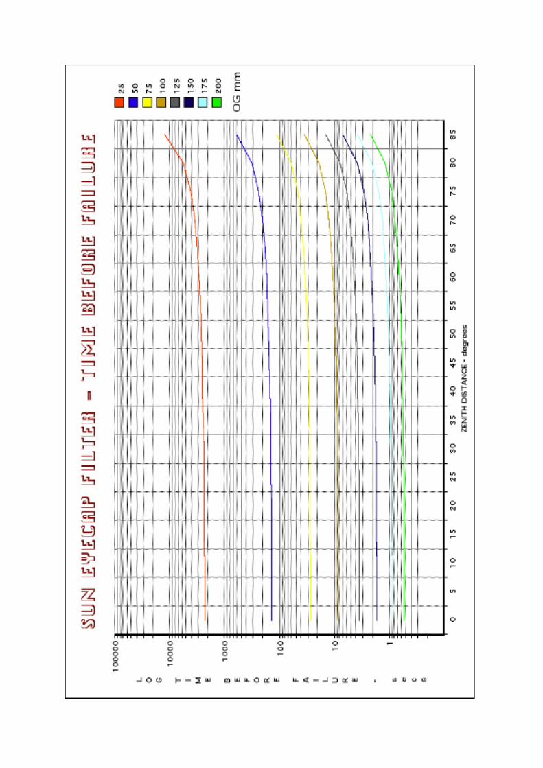


For the 3-inch refractor in question, the time before mechanical failure is only 27 secs after a temperature rise above ambient of 165ºF. Hence if the filter were at 70ºF ambient, at failure it would have risen to 235ºF.
Because the brass cell is spun tightly over the filter glass, the glass cannot actually expand sideways. In reality, with the heat concentrated on the centremost spot, the filter will bulge outwards producing radial fractures.
CONCLUSION
The calculation shows that from a north temperate latitude, at the summer solstice with the Sun on the meridian, in a clear sky, with the eyecap Sun filter screwed onto a 12mm Huyghenian eyepiece, on a 3-inch f/16 refractor (a telescope with which the filter was intended to be used), the filter glass rapidly heats up by 165ºF above ambient and cracks after only 27 seconds. The temperature increase is so rapid and so great that it actually causes the filter glass to rupture. The calculation in this respect is only approximate, as the fundamental mechanical properties of the glass change. In reality the filter would fail sooner. The filter cannot conduct heat into the brass cell rapidly enough to offset the rapid temperature rise because glass has very low thermal conductivity.
You really couldn’t arrive at a less safe arrangement, no sooner have you placed your eye at the eyepiece, accustomed yourself to the view, and focused the image, than the filter shatters.
How dangerous are eyecap Sun filters? About as dangerous as sticking a white hot needle in your eye. The question is, “Do you feel lucky?”
129

EPILOGUE
My findings reveal nothing new, only what “everybody knows”. Eyecap Sun filters are known to be hazardous. All my calculation shows is they can be more hazardous than one might imagine. It does however beg the question, “If eyecap Sun filters shatter so readily on a small refracting telescope, how is it they were made for well over a century?”
My initial calculation was based on a worst case scenario for England. If the Sun were at the zenith the time to failure would be sooner, but what if the Sun is low in the sky, say only 5º altitude?
The solar flux, for a clear sky, is then 270 W/m2. Repeat the calculation for a 2-inch f/12 refractor:
Time before failure = 630 secsTemp rise before failure: 4ºF (filter does not fail)
The heating effect on the filter is low enough for the glass to conduct the heat into the brass cell. Even after over 10 mins at such flux levels the filter wouldn’t fail. At the latitude of Blackpool, the time for observation from Sun altitude 5º to sunset is no more than quarter of an hour. The situation is not true at sunrise, and circumstances would soon become potentially hazardous. Within an hour solar flux will approximately double. However at sunset the atmosphere is likely to be hazy owing to aerosols and dust born aloft by thermals throughout the day. In these circumstances the eyecap Sun filter copes adequately, and as the Sun sets, the image becomes too dim to see. The issue then becomes one of potentially risky solar viewing having removed the filter!
130

At the time eyecap Sun filters were ubiquitous most astronomers would have used them with smaller refractors than generally used nowadays. Urban skies were also more heavily polluted. Apart from the then unknown effects of retinal scotoma caused by IR leakage, when used with a modest aperture late in the afternoon or early morning, the filter would not have failed. Unfortunately they do fail, rapidly, on a slightly larger refractor, and dangerously so. If you have such a filter amongst your accessories, please don’t be tempted to use it.
131

APPENDIX -3
ANTIQUE TELESCOPES in my COLLECTION
Andrew Ross OoW telescope c1850
OFFICER of the WATCH, signed “A Rofs” (Andrew Ross), single draw tan leather barrel, nickel plate, triplet OG was cemented, elements separated
132

B. Cooke & Sons, Hull c1880 3-inch f/15 astronomical refractor in teak case.
3 Huygenian eyepieces, a Pancratic eyepiece and Star diagonal, RAS fitting.
133

B. Wood, Liverpool c1850, black Japaned lacquer barrel, single draw marine, Schyrle-Huygens eyepiece, splash shield and OG cover slide missing, eyecup slide missing.
134
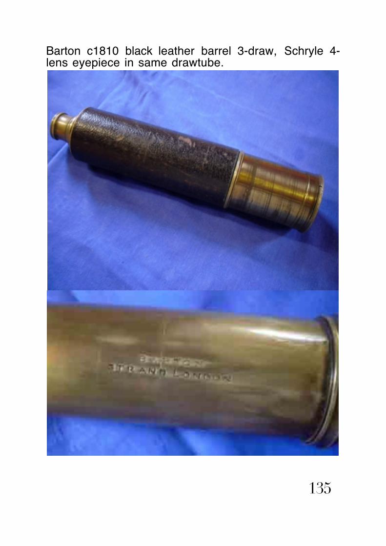
Barton c1810 black leather barrel 3-draw, Schryle 4-lens eyepiece in same drawtube.
135

OoW Broadhurst Clarkson & Co., Ltd., c1920, red leather barrel.
136

C. W. Dixie c1850, 4-draw nickel plate.
137
Charles Wastell Dixey, Optician to the Queen, Bond Street, London, mahogany half barrel, 4-draw, nickel plate

Unsigned single draw marine c1740. Fruitwood taper barrel simple single draw in 3 sections, Schyrle 3-lens eyepiece - each lens in separate drawtube section.
138

Cary, London, all brass 6-draw miniature pocket telescope c1850.
139
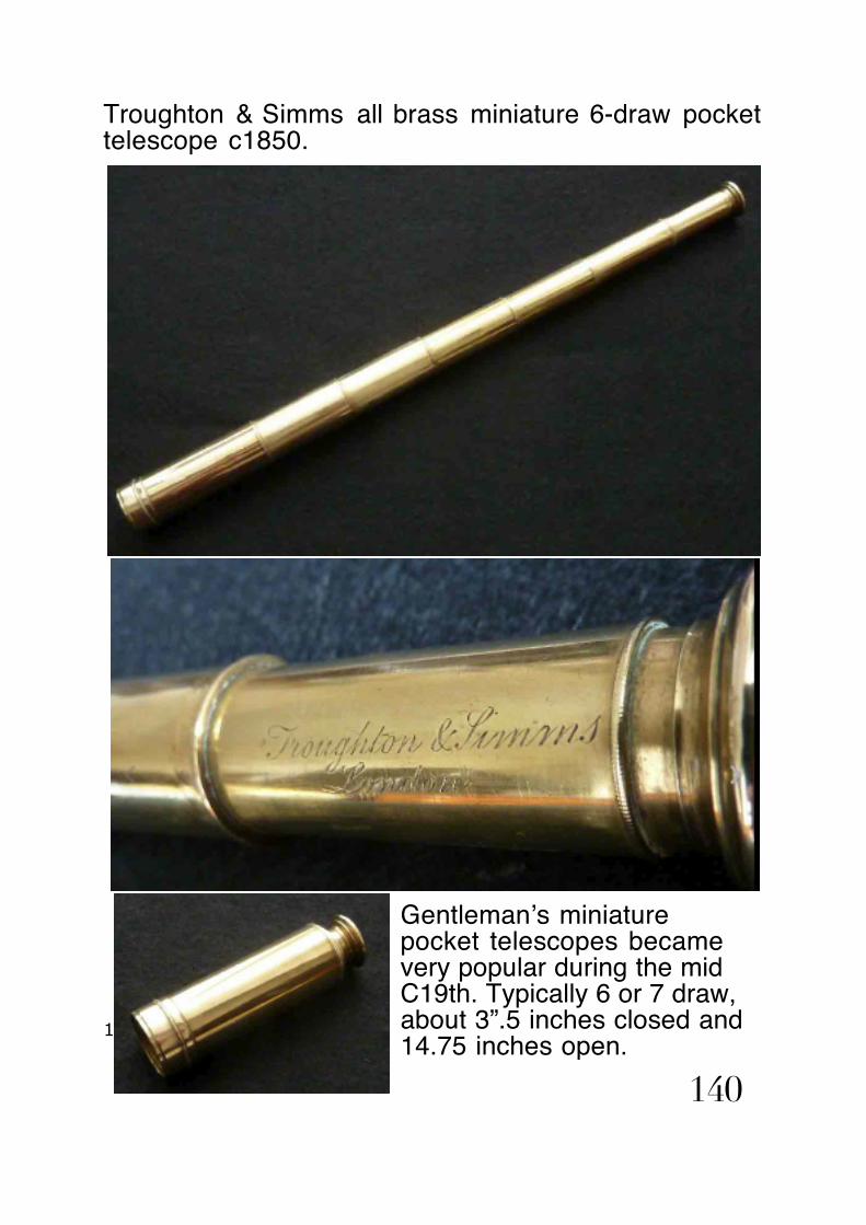
Troughton & Simms all brass miniature 6-draw pocket telescope c1850.
14.75 inches open.
140
Gentleman’s miniature pocket telescopes became very popular during the mid C19th. Typically 6 or 7 draw, about 3”.5 inches closed and 14.75 inches open.
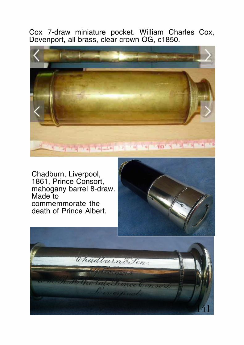
Cox 7-draw miniature pocket. William Charles Cox, Devenport, all brass, clear crown OG, c1850.
141
Chadburn, Liverpool, 1861, Prince Consort, mahogany barrel 8-draw. Made to commemmorate the death of Prince Albert.

Casella c1870, 40-inch table top with pillar & claw stand, and mahogany case.
Louis Paschal Casella, flourished in partnership 1838-1901. Associated with Negretti & Zambra.
142

Charles Lincoln c1760 octagonal mahogany taper barrel, simple single draw with 3 lens Schryle eyepiece.
143

Crichton, London 1863, flame mahogany barrel 3-draw with wood cannister. Owner’s signature on cannister, “Wm Richardson 1863”.
144

George Dixey, mahogany barrel 2-draw marine c1850.
145

George Dixey, c1820, 40-inch table top with pillar & claw stand, & mahogany case.
146

In case before restoration. Note the pitting corrosion to the lacquer. Telescope was restored using method described in section commencing p101.
House of Dixey, Bond Street, London.
147

Dolland c1800, DOLLOND signature intentionally mis-spelt. Mahogany barrel 3-draw Day or Night.
146
148

DOLLOND c1920, brown leather barrel, Signalling 3-draw No. 8291 with leather case & high power eyepiece.
147
149

DOLLOND c 1780, 40-inch red paint taper barrel table top + pillar & claw stand + mahogany case
150

Extract from Reginald Cheetham’s “Old Telescopes”
The mahogany barrel was turned from the solid and finished in red lead paint.
151

DOLLOND c 1780, 50-inch red paint taper barrel table top + pillar & claw stand + mahogany case. Eyepiece has 1.25-inch x 16TPI x 55º screw thread which later became via Henry Maudslay, and Joseph Whitworth the WHITWORTH or WHIT threadform adopted as an Imperial Standard. This screwthread was later adopted by the Royal Astronomical Society in 1847 as the standard astronomical eyepiece screw thread.
152

153

DOLLOND c1800 mahogany barrel single-draw Day or Night.
154

155

DOLLOND c1910, machine engraved with lobate 'o' - field 4-draw in leather case with shoulder strap, variable Pancratic eyepiece, x30, x40, x50, x60.
156

Brown leather barrel 3-draw French - dual power pocket c1890.
Twin Huygenian eyepieces are mounted in the sideways adjustable cylinder. The image needs refocussing after the power is switched.
157

Geo Stebbing, Portsmouth, c1825, mahogany barrel 3-draw pocket with pasteboard linen clad cannister
158

159

George Bracher c1830 mahogany barrel 2-draw (was 3-draw) Day or Night.
160

Gilbert 3-draw c1820 mahogany barrel.
161

Gilbert & Co. c1780 148 Leadenhall Street, London, mahogany taper barrel unretained single draw marine, Whaler's telescope, sinister signature
162

163
Gilbert & Co., 148 Leadenhall Street, London, c1800. Mariner’s single draw achromatic with instructions for cleaning and reassembly of the OG elements.Trade card of the Glasgow optician who originally sold this telescope.

Harris & Sons c1850 3-draw.
signed, “Thos Harris & Sons Opticians to the Royal Family, No. 32 Opposite the British Museum - LondonImproved for Deer Stalking: 164

Harris & Son c1820 mahogany barrel single draw Day or Night.
165

Henry Hughes c1840 single draw mahogany barrel marine.
signed, “H. Hughes, 59 Fenchurch St. London, Day or Night”.
166
Barrel needed a replacement mahogany veneer.

Horne & Thornthwaite, 416 Strand, leather barrel pencil 2-draw, Japanned black lacquer, with leather holster
Late C19th, c1885
167

J. H. Deeble & Sons c1850
J. H. Deeble, Falmouth, black leather bound taper barrel single draw coastguard telescope
168

J. Harry Deeble resided at 35 Arwenack Street, Falmouth and ran a ship’s Chandler’s business H. Deeble & Sons shipchandlers and tug owners.
The telescope would have been bought in and engraved prior to resale.
169

J. Cetti & Co., London c1820 Day or Night mahogany barrel 2-draw with splash shield.
Note the square pegs instead of round. 170

J. H. Steward c1890, 3-draw field telescope, an unsigned “Lord Bury”, drawtube signed “J. H. Steward, 457-406 Strand, 54. Cornhill, London”
The “Lord Bury telescope was a popular 3-draw field hand held with a brass plate rivetted through the leather wrapper. This would be engraved either by the owner, or the presenter of a prize.
This model was made from the early 1890’s thru’ late Edwardian era and the Great War. There were two variants, brass or Duralumin (light) metal, bronzed.
Both models were supplied with a leather sling case.
171

172

Jones c1790 3-draw, mahogany barrel, reverse assembled, sinister signature.
William & Samuel Jones, early achromatic field telescope. The draws were retained, and also the spring collars, making it impossible to dismantle without removing the OG cell and feeding the drawtubes through the front of the barrel.
173
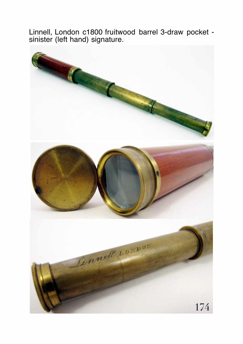
Linnell, London c1800 fruitwood barrel 3-draw pocket - sinister (left hand) signature.
174

Most signatures on antique refractors are engraved in such a manner that the text is upright when the telescope eyepiece is facing right. Sometimes the signature reads the opposite (sinister) way, and would have been engraved left handed.
Note the verdigris on the brass drawtubes. This is not to be confused with patina, which is a dull reddish brown colour. Verdigris is a copper carbonate residue that builds up on the surface of the brass in a damp climate. Repolishing to remove it is essential to the long term preservation of the telescope, using the methods described in the restoration section, pp101-113.
The significance of this little telescope is the maker, George Linnell, son of Elijah and brother of Joseph. Joseph Linnell attempted unsuccessfully to overturn the Dollond patent in 1763.
The fruitwood barrel, probably gage, has been turned and bored from the solid.
Note the crown element of the OG is clear, indicating Linnell was using a source of crown not contaminated with iron.
175

OoW Negretti & Zambra, 1922 signed “Barbara E. Hamilton, Henley Park, Henley on Thames, North Foreland. Sept. 1922”. & “Negretti & Zambra, London, No. 1745.
Tan hide leather barrel with shoulder strap cleats. Nickel plated brass.
176
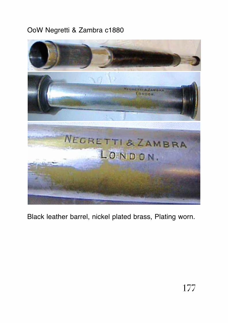
OoW Negretti & Zambra c1880
Black leather barrel, nickel plated brass, Plating worn.
177

Negretti & Zambra c1900 3-inch f/13 astronomical refractor. Black lacquer finish.
178
Sleeve cell OG, common to Negretti & Zambra, Broadhurst Clarkson & Co., Ltd., Ottway & Steward. Indicating the OG’s were supplied from a central source.
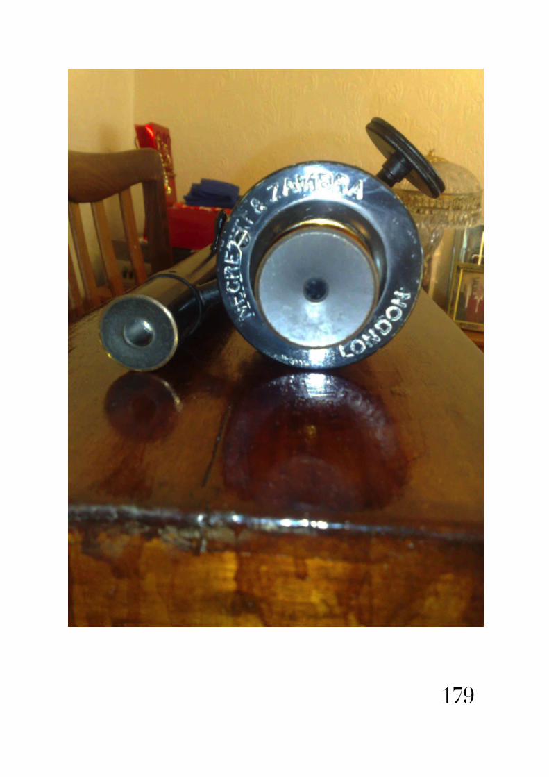
179

F. A. Pizzalla, London, c1850 Day or Night leather barrel single draw marine with splash shield.
Francis Augustus Pizzalla was an Italian immigrant to London around 1830 and made high quality optical instruments in Hatton Garden. Henry Negretti was apprenticed to him from 1838-1845 based at 19 Hatton Garden, London. He showed at the Great Exhibition in London, 1851 and was succeeded by A. Pizzalo in 1854 when the business became the partnership of Piazzala & Greene. Other addresses that Pizzala are known to have operated from are 7 and 20 Charles Street, London. 180

Slugg c1860 leather barrel 3-draw with pasteboard cannister. Josiah Thomas Slugg was a famous Manchester optician in the 1860’s, and promoted amateur astronomy and affordable telescopes.
181

Josiah Thomas Slugg, Manchester, 36" table top with cast iron pillar and claw stand + 3 pancratic eyepieces.
An affordable astronomical refractor made c1865.
182

The eyepieces are all Pancratic (3 different powers) instead of the telescope being supplied with astronomical eyepieces to the RAS standard, and a variable or fixed power terrestrial.
The tube is made from rolled iron, brazed, and wrapped in canvas and painted with red lead and then varnished.
The rack length is very short, less than 2-inches, and the rackmount flange crudley engraved using metal die punches.
The pillar & claw stand is made from cast iron, and the alt-az head is very crude. Resistance in altitude being far stiffer than resistance in azimuth.
The telescope may have been “affordable”, but it demonstrates you only get what you pay for! 183
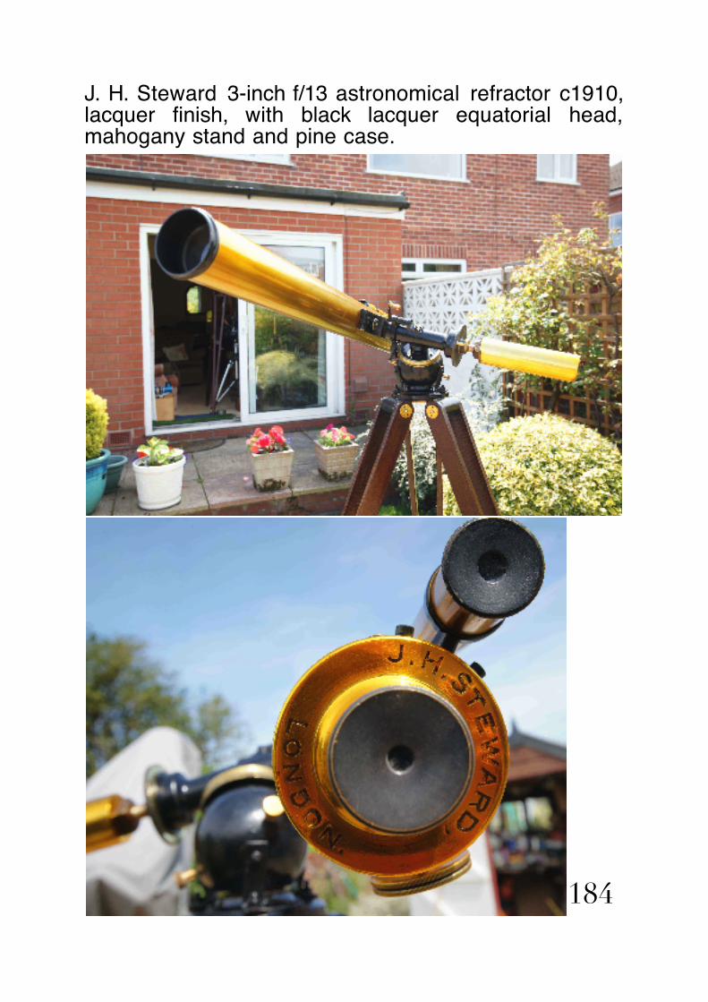
J. H. Steward 3-inch f/13 astronomical refractor c1910, lacquer finish, with black lacquer equatorial head, mahogany stand and pine case.
184

185

T. Harris & Son c1800 Day or Night mahogany barrel single draw marine.
Thos Harris & Son c1890 Day or Night mahogany barrel single draw marine with splash shield.
Thomas Harris & Son were a prolific and long flourishing firm. Thomas (I) Harris & William (II) were in business from 1790 well into the early C20th.
186

T. Harris & Son, London, Day-Or Night, mahogany barrel single draw marine, c1870.
187

cont. T. Harris & Son, London, Day-Or Night, mahogany barrel single draw marine, c1870.
188

Thomas (I) Jones 50-inch table top c1835, + pillar & claw stand with triple extension elevation rod + mahogany case - substitute OG c1970 & brass cell
Thos(I) Jones foreground table top in display.
189

Thomas (I) Jones established a flourishing instrument making business from 1806 - 1861, in partnership with his son Thomas (II) at 62 Charing Cross Road, London 1831-35. Thomas (I) Jones was apprenticed to Jesse Ramsden, and worked for him and under Matthew Berge, Ramsden’s charge hand.
This particularly fine instrument was rescued from Shrewsbury museum in the early summer of 190

2014. Unfortunately the original OG was missing. The uncoated cemented achromatic doublet from a TASCO 10TE was substituted, and a matching brass cell in the style of the maker machined to fit the tube.
Table top telescopes of this size, the largest made, were intended to adorn a gentleman’s library.
191

Tulley & Sons c1820. Mahogany barrel 5-draw engraved N.S.L. X3845. Kitchiner variable power Pancratic eyepiece. In the first draw there is an internal tube which can be extended once the eyepiece is removed, thus giving a Pancratic draw and increasing the magnification considerably.
This appears to be one of the first Pancratic telescopes made? W. M. Kitchiner produced various Pancratic draws during the early C19th and Charles Tulley around this time sold Kitchiner some large telescopes.
Charles Tulley was a legendary lens and telescope maker whose lens work surpassed the Dollonds.
192

193

Watkins c1790-1810, 7-draw mahogany barrel pocket telescope with leather cannister.
194

195

cont. Watkins c1790-1810, 7-draw pocket telescope.
Compact pocket telescopes of this style were made from the late C18th right thru’ the C19th by various instrument makers.
Jeremiah Watkins took over Francis (I) Watkins’ business at 4/5, (5) Charing Cross Road, London, and operated between 1798 & 1810. With Walter Watkins from 1784-1798.
Francis (I) Watkins, the uncle of Jeremiah, was in partnership with John (I) Dollond, having paid for Dollond’s patent. Francis Watkins was elected 196

Master of the Worshipfull Company of Spectacle Makers, and led the petition to have the patent revoked.
Note the marked greenish caste to the front (crown) component of the achromatic doublet. All crown glass at this time, in England, was made using potash obtained from Kelp, to reduce the melting temperature, and make it less viscous at it’s melting point. A residual element in Kelp is iron, which was not destroyed in the reduction to potash. It is iron in the crown glass which gives it this noticeably characteristic pale green hue.
197
The barrel is of interesting construction. A brass thin wall tube wrapped in a thin Honduran mahogany veneer.
The rear spring draw flange is trapped by a brass collar.
The eyecup has an eyestop missing.
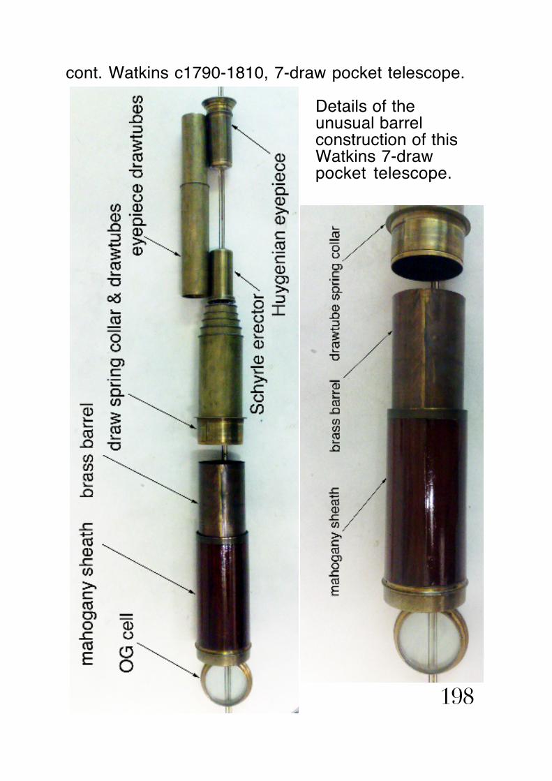
cont. Watkins c1790-1810, 7-draw pocket telescope.
198
Details of the unusual barrel construction of this Watkins 7-draw pocket telescope.

The barrel is made from a thin wall rolled and seam soldered brass tube, with the thread for the drawtube spring collar turned on the I.D.
A thin Honduran mahogany veneer was then steamed and rolled around the barrel, which in effect became a sleeve. The veneer became a sheath. The OG cell front flange was then pinned through the sheath and the sleeve. At some stage the pins must have come loose because it has been repinned, and now the pins are missing altogether.
The drawtube spring collar, carrying the seven drawtubes is screwed into the brass sleeve. The eyecup screws over the end of the eyepiece, and would have had an eyestop recessed into it to facilitate pupil centring.
The erector is contained within the sixth draw and the Huygenian eyepiece is screwed into the seventh draw.The drawtube spring collars each have shouldered screw threads. This design modification was introduced by George (I) Dollond, and Watkins must have been amongst the earliest contemporary instrument makers to adopt it. Because the overhung cantilever loads are distributed over the length of the collars, the telescope is less prone to droop, and is much more robust.
Although this form of construction is unusual, it does get around the problem of strength vs weight, bearing in mind it is a compact pocket telescope, and therefore the lighter the better.
199

Parnell 2-draw Day or Night c1815. Mahogany barrel marine.
William Parnell was the son of Thomas Parnell, and a shipchandler and mathematical instrument maker whose business premises were located in Smithfield at the sign of The Mariner & Quadrant. His business flourished 1811-1839.
200
OG cover slide & eyecup cover slide

This style of 2-draw marine, which collapsed down to approximately 15-inches was in common use throughout the naval campaigns of the Napoleonic Wars.
Deck Offices preferred it because it was more compact and easier to carry, extending to about 32-inches in Day use and 22-inches in Night use. A similar telescope is shown in the opening scenes of the movie “Master & Commander”.
The earlier single draw taper mahogany barrel marine telescopes were more cumbersome being about 26-inches long when stowed.
201
OG splash shield

OoW Watson & Sons, c1899, 313 High Holborn, London, leather bound barrel
202

203

Weichart, Bute Docks, Cardiff c1850, single draw marine, Day or Night, dark brown leather barrel.
204

This style of single draw marine became popular in the 1830’s and remained so through the early C20th. It was less expensive than a mahogany barrel equivalent.
William Weichart chandlers business flourished in the 1830’s.
205

Baker, 244 High Holborn, London, c1875, 4-draw pocket telescope nickel plate, Baleen wrapped.
206

207

A 4 draw nickel silver and Baleen covered telescope, signed 'Baker 244 High Holborn London' and also signed on the eyepiece “James Dakin 11th Feby 1823”.
There is a sunshade or splash shield with an attractive engraved monogram ‘JD’. The draw tubes have some minor dints commensurate with age, however all draws slide freely in their felt lined collars.The Baleen wound barrel is all intact apart from a couple of losses to one side. Length closed 8”; extended 30”.75.
I have not been able to trace James Dakin & the telescope cannot date from that engraved on the eye cup because EPNS process was invented in Sheffield in the early 1840’s. The design and construction is remarkably similar to a Prince Consort telescope in my collection, which can be dated to shortly after Prince Albert’s death 14th December 1861 & was issued as a commemorative telescope the folowing year (p141). I have estimated this telescope was made c1875 after consulting Gloria Clifton’s directory. Charles Baker’s business flourished at the High Holborn address between 1851 and 1909.
The eye cup inscription may commemorate the owner’s date of birth.
208

Charles Lincoln non-achromatic single draw c1760.
209

Charles Lincoln’s business at 11 Cornhill & 38 Leadenhall Street, London, flourished between 1763 and 1805.
This small telescope has a simple OG, not stopped down, only 1/2-inch aperture. It has a taper octagonal mahogany barrel, and a 3-lens Schyrle eyepiece.
Henry (1) Gregory Leadenhall Street, London telescope, dating c.1760.
Henry (1) Gregory’s business at Leadenhall Street, flourished between 1744 and 1782.
The eyepiece is the same 3-lens Schryle type as in the Lincoln.
210

This is an early crown forward achromatic telescope c1760 and has a reverse taper decagonal mahogany barrel. It has a single unretained brass draw tube, signed 'Gregory London'. The telescope has brass sliding lens covers to the eye piece and objective lens.
211

Dollond achromatic c1770 unretained single draw with 5 lens eyepiece, and Shagreen wrapper.
212

Early Dollond small achromat, 3/4” dia. stopped down by the cover slide to 5/8” clear aperture. Note the greensih cast to the lens, caused by iron contamination to the crown.
The drawtube is not retained, meaning it can be withdrawn by accident. It comprises 5 sections, each with a plano convex lens and a stop. It is a rare example of a 5-lens Schryle erecting eyepiece.
The Shagreen wrapper is cut from Stingray hide. Shagreen was a luxury covering material in the C18th.
Extended length 18”, closed 10”.5 213
Early Dollond doublet, stopped down from 3/4” to 5/8”. Lenses spun into cell.

214
G. Bracher, London, Day or Night single draw marine with tarred string bound iron barrel c1840. George Bracher’s instrument making business flourished at 19 & 20 King Street, Commercial Road East, London between 1826 and 1840. His widow Mary ran the business from 1841 to 1843.

215
Unsigned 3-draw pocket telescope, French spiral rope binding with Turk’s heads c1860.

216
I. Parkes, London, 4-draw pocket telescope, rope French twist binding with Turk’s heads c1860.

217
Officer of the Watch telescope, Ross, London, c1840. Dark brown plaid rope binding with Turk’s heads. Signed A.W.B. Kirvan R.N.

218
Officer of the Watch telescope, Hammersley, London c1900, Tan leather with Turk’s heads. Signed, :Manufactured for J. Highatt, High Street, Gosport”.

219
Ross Officer of the Watch telescope c1940. No. 59172, signed,”Made for Gieve Matthews & Seagrove Ltd., London, Portsmouth & Devonport”. Owner’s signature on barrel end, “Lieut. M.B.B. Birkett R.N.” with Turk’s heads.

NOTES:
Ammonia may have detrimental effects on brass over long periods (i.e. in decades), it may cause hardening of the metal surface.
Theoretically, Ammonia reacts with copper and forms the cuprammonium ion [Cu(NH3)4], a chemical complex which is water soluble and hence washes within the growing cracks.
Citric acid powder dissolved in boiling water at a ratio of approximately 2 ounces to an imperial gallon, and stirred with a wooden spoon may be used to removed verdigris and tarnish, and leave a matt finish. This is the preferred method of cleaning graduated scales engraved into brass. To neutralise, immerse in warm water with soda crystals dissolved at a similar ratio, then rinse in cold water and dry. Note that citric acid solution will not remove lacquer.
220

BIBLIOGRAPHY
Astronomical telescopes, A. G. Today, HMSO 1971Antique Scientific Instruments, G. L’E Turner, Blandford Press, 1980Scientific Trade Cards, H.R. Calvert, HMSO 1971Directory of British Scientific Instrument Makers 1550-1851, Gloria Clifton editor Gerard L’E Turner, Zwemmer, 1995Science Preserved, a directory of scientific instruments in collections in the United Kingdom and Eire,Mary Holbrook, HMSO 1992 Making Scientific Instruments in the Industrial Revolution, A.D. Morrison-Low, Ashgate, 2007Collecting Old Telescopes, Peter HuntOld Telescopes, Reginald J. Cheetham, Samedie 1997Collecting and Restoring Scientific Instruments, Ronald Pearsall, ARCO 1974The Officer of the Watch Telescope, 100 Years of Naval Tradition, Brian Buckman, Outskirts Press, 2012Transit Circle, The Story of William Simms 1793-1860, Eleanor Mennim, Ebor Press, York Instrument Makers to the World, A History of Cooke, Troughton & Simms, Anita McConnell, Ebor Press, York 1992Francis Watkins and the Dollond Patent Controversy, Brian Gee, edited by Anita McConnell and A.D. Morrison-Low, Ashgate, 2014Eyes Right, the Story of Dollond & Aitchison 1750-1985Hugh Barty-King, Quiller Press, 1986Adams of Fleet Street, Instrument makers to King George III, John R. Milburn, Ashgate, 2000Jesse Ramsden, (1735-1800) London’s Leading Scientific Instrument Maker, Anita McConnell, Ashgate, 2007
221

LIST of FIGURES
1 OPTICS OF THE GALILEAN REFRACTOR2 GEOMETRIC RAY TRACE GALILEAN3. GEOMETRIC RAY TRACE KEPLERIAN4 GEOMETRIC RAY TRACE SCHEINERIAN5 GEOMETRIC RAY TRACE SCHYRLEAN6 GEOMETRIC RAY TRACE 3-LENS EYEPIECE 7a GEOMETRIC RAY TRACE 4-LENS EYEPIECE7b GEOMETRIC RAY TRACE 4-LENS MODIFIED7c GEOMETRIC RAY TRACE CAMPANI 3-LENS8a GEOMETRIC RAY TRACE HUYGENIAN 2-LENS8b HUYGENIAN EYEPIECE DIAGRAM9 DOLLOND PANCRATIC EYEPIECE 4-LENS10 SCHYRLE-HUYGENS ERECTOR 1st ORDER11 ACHROMATIC DOUBLET12 DOLLOND’S DOUBLET OBJECT GLASS13 DOLLOND’S TRIPLET OBJECT GLASS14 ACHROMATIC REFRACTOR DIAGRAM15 RAMSDEN EYEPIECE DIAGRAM16 ACHROMATIC GALILEAN17 ACHROMATIC DOUBLET RAY PATHS18a ACHROMAT SECONDARY SPECTRUM18b APOCHROMAT SECONDARY SPECTRUM19 ANTIQUE REFRACTOR DESIGN20a PASTEBOARD MID C18TH TELESCOPES20b SIMPLE UNSIGNED c174021 REVERSE TAPER OCTAGONAL c175022 EYEPIECE CONSTRUCTION23 COUPLINGS & RETENTION24 OBJECTIVE LENS MOUNTING25 OBJECTIVE LENS MOUNTING FOR TRIPLETS26 EYECUP STYLES27 TAPER EYECUP STYLES28 FLARED EYECUP STYLES29 OBJECT GLASSES
222

LIST of FIGURES (cont)
30 OBJECT GLASSES31 OBJECT GLASS BY TROUGHTON & SIMMS32 EXAMPLES OF OLD REFRACTORS33 FRODSHAM, J. CETTI, J. HUGHES & BARTON34a OBJECTIVE CELL ARRANGEMENTS34b EYEPIECE ARRANGEMENTS35 SIGNATURES36 BRASS JOBBER’S ASSEMBLY MARKS37 CANNISTERS & TRUNKS38 UNSIGNED SIMPLE SINGLE DRAW c184039 COMPARISON OF FRODSHAM, LILLEY&GILLIE40 COMPARISON OF FRODSHAM, LILLEY&GILLIE41 UNSIGNED MASTERPIECE aka FRODSHAM42 SIGNALLING & POCKET REFRACTORS43 RETRACTED HAND HELD REFRACTORS44 OFFICER OF THE WATCH TELESCOPE c191545 HUSBANDS TABLE TOP TELESCOPE c187046 SIGNATURE ON RACK & PINION BODY47 HENRY HUSBANDS PILLAR & CLAW STAND48 HUSBANDS 2-INCH ACHROMATIC OBJECTIVE49 HUSBANDS TABLE TOP ACHROMATIC50 HUSBANDS TABLE TOP ACHROMATIC51 HUSBANDS 4-LENS EYEPIECE ARRANGEMENT52 UNSIGNED TABLE TOP 2-DRAW c1850-190053 UNSIGNED TABLE TOP 2-DRAW c1850-190054 TROUGHTON & SIMMS TABLE TOP c185055 TROUGHTON & SIMMS SIGNATURE56 TROUGHTON & SIMMS CASED57 TRADE CARD TROUGHTON & SIMMS58 TRADE CARD HENRY HUSBANDS59 TROUGHTON & SIMMS SIGNATURE60 3-INCH UNSIGNED ASTRONOMICAL c188061 TULLEY 5-FOOT ACHROMATIC c183062 TULLEY & SONS SIGNATURE
223

LIST of FIGURES (cont)
63 TULLEY OBJECT GLASS64 TULLEY IN CASE65 THE BARLOW LENS66 RAMSDEN TABLE TOP TELESCOPE c179067 BERGE TABLE TOP TELESCOPE c181068 HUSBANDS CLAW LEGS69 HUSBANDS CLAW LEGS HINGE BOSS70 FLAG PANEL MARINE TELESCOPE71 5 SHADES OF IRGALITE LACQUER72 TROUGHTON & SIMMS BEFORE RENOVATION73 TROUGHTON & SIMMS CASED74 PILLAR & CLAW STAND75 TROUGHTON & SIMMS, RESTORED IN CASE76 TROUGHTON & SIMMS RESTORED SIGNATURE77 TROUGHTON & SIMMS REPOLISHING78 CLARKSON SUN & STAR DIAGONAL79 OPTICAL RAY PATH SUN DIAGONAL MODE80 OPTICAL RAY PATH STAR DIAGONAL MODE81 SUN EYECAP FILTER IN CELL82 SUN EYECAP SCREWED ONTO EYEPIECE82a SOLAR FLUX SCHEMATIC
224

INDEX Aaronsberg, William 113Abbé Orthoskop 27Achromatic 17, 25, 30, 34, 36, 56achromatic astronomical refractor 25, 28, 34, 84, 87,
92, 104, 178, 179Achromatic doublet 31, 32, 34, 49Achromatic Galilean 30Achromatic terrestrial 19Adams 98, 113afocal 5Airy George B. 15Aitchison 113altazimuthal 26, 86, 93Antheaulme 33Anton Maria Schyrleus de Rheita 8Aplanatic 36Apochromatic objective 34, 35apparent fov 7, 29Aspheric doublet 21Ayscough James 20
Badovere Jacques 1Baker, Charles 206, 207, 208Baleen 52, 206Barlow lens 90, 91, 92Barlow Peter 90Barton 57, 58, 59, 60, 63, 135Bass George 20, 33Benediktbeuern 34Bennet, J.A. 36Berge John 95Berge Matthew 95, 113, 190Bevis John 21bi-concave lens 32bi-convex lens 31, 32Bird John 20 225

Boscovitch R. J. 33Bracher, George 160, 214Brasso 102, 103, 106, 107, 111Broadhurst, Clarkson & Co., Ltd. 84, 90, 113, 118,
119, 136, 178Browning 113Burton John 24Burton Mark 24
Cabriolé legs 95Campani 10Cannister, leather 194Cannister, pasteboard 181Cannisters & trunks 63, 144, 158Cary 113, 139Casartelli, Joseph 113Cascamite glue 110Casella, L. P. 142Ceti John & Co. 57, 58, 59, 60, 113, 170Chadburn 141Chance Bros56Cheetham, Reginald 151chromatic 4Clairaut Alexis 33, 36, 49Clarke William 75, 78Clarkson Alexander 88, 90, 113, 118, 119clocking 50Coastguard telescopes 66, 67, 69,168,169Colour screens 89coma 15, 37Comet eyepiece 27Conrady limit12Conrady triplet OG 84Cooke Thomas 37, 88, 113Cooke, B. & Sons 133Cooke, T. & Sons 72Cosmoloid wax 112Cox, W. C. 141 226

Crichton 144Crown glass 17
Dancer John 113Dancer, John 113Day or Night 9, 28, 4546, 148, 154, 155, 160, 165, 166,
170, 187de l'Estang 33Declination DEC 93, 94Deeble, J. H. & Sons 168, 169Deer stalking telescope 164depth of focus 12diffraction limited 11Dioptrica 13Dioptrice 5Directory of British Scientific Instrument Makers 113Dixey, George 145, 146, 147Dixie, C. W. 137Doland 22Dolland 148, 154, 155Dollond 98, 113, 149, 156, 175, 196, 212, 213Dollond 40-inch table top 150, 151Dollond 50-inch table top 152, 153Dollond achromatic 212, 213Dollond Day or Night 148, 154, 155Dollond deer stalker's telescope 149, 156Dollond George 48, 199Dollond John 17, 21, 22, 32, 33, 46, 113, 196Dollond Peter 21, 22, 26, 46, 95Dubbin 111, 112Duraglit 103Duralumin 171Dutch Trunk 1
Earl of Sandwich's Arrow 73effective focal length 6, 7Emery paper102, 103equatorial mount 26, 86, 93, 94 227

erecting refractor 1erector 9, 26, 27, 42, 46, 101Euler Leonard 21exit pupil 3eye clearance 28eye pupil 3eyecap filters 122, 123, 124, 125, 126, 129, 130eyecup styles 53, 54, 55eyepiece apparent fov 6
Field glass 4, 30field stop 6Finder 'scope 29Flag panel marine 97Flint glass 17, 46Fob watch spherometer 101focal ratio 4Fontana Francesco 5French spiral binding 215, 216Frodsham Henry 57, 58, 59, 60, 66, 67, 68, 113
Galilean 3Galilean telescope 3Galilei Galileo 1Gardner James 63Gilbert 161Gilbert & Co. 162, 163GMT Greenwich Mean Time 94Gregory David 20Gregory, Henry 211Grubb Thomas 37Guinand Pierre Louis 34
Haematite patinator 103Hall, Chester Moor 20Hammersley 218Harris 113Harris & Son 165 228
Harris & Sons 164Harris, T. & Son 186, 187, 188Harris, Thomas & Son 50Herschel Wedge 27, 89, 118, 119Herschel, J.F.W. 36Hevelius, Johannes 11Hide wood glue 110, 111Hilger & Watts 113Hinge boss 96Hooke Robert 19Horne & Thornthwaite 113, 167Hour angle 94Hughes Henry 113, 166Hughes John 57, 58, 59, 60Husbands & Sons 75Husbands Henry 74, 75, 77, 82, 83, 96, 113Huygenian eyepiece 13, 15, 26, 28, 29, 46, 122, 129,
133, 157Huygens Christiaan 11Huygens Constantijn 11
Irgalite dye 104Irving, H. N. & Sons 92
J. J. von Littrow 36, 49J. Lilley & Gillie 66, 67Jannsen Zacharias 1Japanned black lacquer 167Jean-Baptiste le Rond d’ Alembert 33Jobber's marks 62, 64, 101John Burchard von Schyrle 8Jones, Thomas 50-inch table top 189, 190Jones, William & Samuel 113, 173Joseph von Fraunhofer 34, 37, 49Joseph von Utzschneider 34, 37, 49
Kellner eyepiece 27Kepler Johannes 5 229

Keplerian 5, 42Keplerian telescope 5, 42Kitchiner William 17, 192Klingenstierna Samuel 21
lateral chromatic aberration 15, 28lateral colour error 15Lead chromate 96Lincoln, Charles 143 209, 210Linnel, George 174Linnel, Joseph 175Lipperhey Hans 1Littrow objective 37Local Sidereal Time LSTlongitudinal chromatic aberration (LCA) 4, 12, 28, 32,
33, 64longitudinal spherical aberration (LSA) 4, 28, 32, 33,
64Lord Bury telescope 171Luminiferous Aether 11
Mann James 20Martin Benjamin 22, 46, 113Martin Joshua Lover 46Maudslay Henry 152Mauritz Prince of Nasseau1Merz & Mahler 37Metius Jacob 1Minature pocket telescope 139, 140Muntz brass 104, 116
Negretti & Zambra 113, 142, 176, 177, 178, 179Negretti Henry 180Newton Isaac 19Nitro-cellulose lacquer 104, 105
object glass (OG) 4Objective clocking 50 230

Officer of the Watch telescope 72, 73, 132, 136, 176, 177, 202, 203, 217, 218, 219
Opera glass 4, 30Opsuscules Mathématiques 33Ottway 89. 113, 178
Pancratic eyepiece 17, 26, 58, 101, 133, 183,192paraxial optical path distance 4paraxial rays 32Parkes, I. 216Parnell, William 200, 201Pasteboard telescopes 43, 48Pillar & Claw stand 26, 74, 93, 94, 95, 108, 109, 142,
150, 152, 182, 183Pitting corrosion 104, 105, 106, 108, 109, 110Pizzalla, F. A. 180Plaid rope binding 217plano-convex 13polar distance 93Potter Richard 37PreLim 102, 103, 107Prince Consort telescope 141, 208
Rack & pinion motion 93Ramsden eyepiece 15, 29, 30, 90Ramsden Jesse 15, 23, 26, 27, 28, 29, 46, 98, 95, 113,
190RAS eyepiece screw thread 88, 133, 152Rayleigh criterion11Rayleigh limit 4Red brass 104, 106, 107, 115Red lead paint 151refractive index 31refractive indices 33Renaissance wax 103, 106, 107, 111, 112Renovation 101Reverse taper telescope 45, 211 231

Right ascension RA 94Rosa Ursina 6Ross, Andrew 113, 132, 217, 219
Saddle soap 111, 112Sarpi Paolo 1Scarlett William 20Scheiner Christopher 5Scheinerian 6Schryle-Huygens eyepiece 16, 26, 42, 46, 58, 65,
68, 79, 97, 101, 134,135Schryleus de Rheita 5Schyrle 3-lens eyepiece 138, 143, 210-Schyrle 5-lens eyepiece 213Schyrlean 8, 26, 44Season cracking 84, 107Secondary spectrum 34Selenium compound 96, 103Semitecolo Leonardo 50Shagreen 212, 213Shellac varnish 103, 111Sidereal time 94Sidereus Nuncius 1Signalling & pocket refractors 70, 71, 149Signatures 59, 61, 173Simms William 117Sine condition 37Slow motions 93Slugg, J. H. 181, 182, 183South, Sir James 36Spencer Browning & Rust 113spherical 4, 37sphero-chromatism 37Splash shield 201Star diagonal 27, 118, 119, 133Stebbing, Geo. 158, 159Steinheil Monocentric 27
232
Steward, J. H. 88, 113, 171, 172, 178, 184, 185stop plate 10Sun & Star diagonal combined 118, 119, 120, 121Sun (solar) diagonal 119Sun screen filter 89, 122, 123
Table top telescope 74, 81Troughton & Simms 81, 82, 83, 86, 108, 109, 111,
113, 117, 140Tulley & Sons 86, 87, 113, 192, 193Tulley Charles 17, 36, 46, 113Turks heads 215, 216, 217, 218, 219
UT Universal Time Co-ordinated UTC 94
Watkins 113, 194, 195, 196, 197, 198, 199Watkins & Linnell 22Watson W. & Sons 88, 90, 113, 118, 119, 202, 203Webster's Instrument Maker's Biographies 113Webster's Instrument Makers Database 59, 100Weichart, William 204, 205Whaler's telescope 162Whitworth Joseph 152Wiesel Johannes 8Wood, B. 134Wray 88
233