KJ 73-A - Far Bologna
32
KJ 73-A I GB - ISTRUZIONI ORIGINALI RIVETTATRICE OLEOPNEUMATICA PER INSERTI 6 - 32 ÷ 1/2" - 13 UNC ISTRUZIONI D’USO - PARTI DI RICAMBIO - TRANSLATION OF ORIGINAL INSTRUCTIONS HYDROPNEUMATIC RIVETING TOOL FOR INSERTS 6 - 32 ÷ 1/2" - 13 UNC INSTRUCTIONS FOR USE - SPARE PARTS KJ 73-A
-
Upload
khangminh22 -
Category
Documents
-
view
1 -
download
0
Transcript of KJ 73-A - Far Bologna

KJ 73-AI
GB
- ISTRUZIONI ORIGINALIRIVETTATRICE OLEOPNEUMATICA PER INSERTI 6 - 32 ÷ 1/2" - 13 UNCISTRUZIONI D’USO - PARTI DI RICAMBIO
- TRANSLATION OF ORIGINAL INSTRUCTIONSHYDROPNEUMATIC RIVETING TOOL FOR INSERTS 6 - 32 ÷ 1/2" - 13 UNCINSTRUCTIONS FOR USE - SPARE PARTS
KJ 73-A

KJ 73-A
Far S.r.l. - Massimo Generali
(Presidente del Consiglio di Amministrazione)(Chairman of the Board of Directors)
(Président du Conseil d’Administration)(Vorsitzender des Verwaltungsrates)
(Presidente del Consejo de Administración)(Prezes Zarzadu)
(Председатель Административного Совета)
.............................................
La sottoscritta Far S.r.l., con sede in Quarto Inferiore (BO) alla via Giovanni XXIII n° 2,DICHIARA
sotto la propria esclusiva responsabilità che la rivettatrice Modello KJ 73-A - Rivettatrice oleopneumatica Utilizzo: per inserti filettati 6-32 ÷ 1/2"-13 UNC, numero di serie: vedi retro copertina, alla quale questa dichiarazione si riferisce è conforme ai requisiti essenziali di sicurezza previsti dal D. Lgs. 17/2010 di recepimento della Direttiva Macchine 2006/42/CE e successive modificazioni ed integrazioni, e CU TR 010/2011. La persona autorizzata a costituire il fascicolo tecnico risponde al nome di Massimo Generali, presso la Far S.r.l., con sede in Quarto Inferiore (BO) alla via Giovanni XXIII n° 2.
The undersigned Far S.r.l., having its office in Quarto Inferiore (BO), Via Giovanni XXIII No. 2, herewithDECLARES
on its sole responsability that the riveting machine Type KJ 73-A - Hydropneumatic tool Application: for threaded inserts 6-32 ÷ 1/2"-13 UNC, serial number: see back cover, which is the object of this declaration complies with the basic safety requirements estabilished in the law decree Leg.D. 17/2010 of the Machinery Directive 2006/42/CE acknowledge and subsequent amendments and integrations and CU TR 010/2011. The person who is authorized to create the technical brochure is Massimo Generali, c/o Far S.r.l., head office in Quarto Inferiore (BO), via Giovanni XXIII n. 2.
Quarto Inferiore, 04-11-2020
I
GB

I
I
ISTRUZIONI D’USO.................................................4
INSTRUCTIONS FOR USE .....................................13
PARTI DI RICAMBIO .............................................22
SPARE PARTS .......................................................24
KJ 73-AGB
GB

I KJ 73-A
4 75036141 - KJ 73-A – rev 02 - ( 06-2022 )
AVVERTENZE E MISURE Dl SICUREZZA
ISTRUZIONI D’USO I
INDICE
GARANZIA ............................................................................4AVVERTENZE E MISURE DI SICUREZZA ...............................4IDENTIFICAZIONE DELLA RIVETTATRICE .............................5NOTE GENERALI E CAMPO DI APPLICAZIONE .....................5PARTI PRINCIPALI ................................................................5DATI TECNICI ........................................................................5ALIMENTAZIONE DELL’ARIA .................................................6OPERAZIONI PRELIMINARI ..................................................6POSA IN OPERA DELL’INSERTO ...........................................7ANOMALIE DI FUNZIONAMENTO..........................................8CAMBIO DI FORMATO ..........................................................8REGOLAZIONE DEL GRUPPO TIRANTE TESTINA ...............10RABBOCCO OLIO NEL CIRCUITO OLEODINAMICO .............11MANUTENZIONE .................................................................12SMALTIMENTO DELLA RIVETTATRICE ...............................12
ATTENZIONE!!!La mancata osservanza o trascuratezza delle seguenti avvertenze di sicurezza può avere conseguenze sulla vostra o altrui incolumità e sul buon funzionamento dell’utensile.
•Leggereattentamenteleistruzioniprimadell’uso.•Perleoperazionidimanutenzionee/oriparazioneaffidarsi
a centri di assistenza autorizzati dalla FAR s.r.l. e fare uso esclusivo di pezzi di ricambio originali. La FAR s.r.l. declina ogni responsabilità per danni da particolari difettosi, che si dovessero verificare per inadempienza di quanto sopra (Direttiva CEE 85/374).
L’ELENCO DEI CENTRI DI ASSISTENZA È DISPONIBILE SUL NS. SITO WEB: http://www.far.bo.it ( Organizzazione )
GARANZIA
Le rivettatrici FAR sono coperte da garanzia di 12 mesi. Il periodo di garanzia dell'attrezzo decorre dal momento della sua comprovata ricezione da parte dell'acquirente. La garanzia copre l'utente/acquirente quando l'attrezzo viene acquistato attraverso un rivenditore autorizzato e solo quando viene impiegato per gli usi per i quali è stato concepito. La garanzia non è valida se l'attrezzo non viene utilizzato e se non viene sottoposto a manutenzione come specificato nel manuale di istruzione e manutenzione. In caso di difetti o guasti la FAR S.r.l. si impegna unicamente a riparare e/o sostituire, a propria discrezione esclusiva, i componenti giudicati difettosi.
• Si raccomanda l’uso dell’utensile da parte di personalespecializzato.
• Durante l’impiego dell’utensile, usare occhiali o visiereprotettive e guanti.
• Pereseguireleoperazionidimanutenzionee/odiregolazionedell’utensile utilizzare gli accessori in dotazione e/o le attrezzature commerciali indicate nel capitolo Manutenzione.
• Per le operazioni di carica olio, usare solo fluidi concaratteristiche indicate nel presente fascicolo.
• Incasodiperditeaccidentalidioliochedovesserovenirea contatto con la pelle, lavarsi accuratamente con acqua e sapone alcalino.
• L’utensilepuòesseretrasportatoamanoedèconsigliabile,dopo l’uso, riporlo nel proprio imballo.
• Non esistono particolari prescrizioni per lo stoccaggio ol'immagazzinamento.
• Si consiglia ai fini di un corretto funzionamento dellarivettatrice, una revisione semestrale.
• Gliinterventidiriparazioneepuliziadell’utensiledovrannoessere eseguiti con macchina non alimentata dall’aria compressa.
• È consigliabile, ove possibile, I’uso di un bilanciatore disicurezza.
• Incasodiesposizionequotidianapersonaleinambienteilcui livello di pressione acustica dell’emissione ponderata A sia superiore al limite di sicurezza di 70 dB (A), fare uso di adeguati mezzi individuali di protezione dell’udito (cuffia o tappo antirumore, diminuzione del tempo di esposizione quotidiana etc...).
• Mantenereilbancoe/ol’areadilavoropulitaeordinata,ildisordine può causare danni alla persona.
• Non lasciare che persone estranee al lavoro tocchino gliutensili.
• Assicurarsicheitubidialimentazionedell’ariacompressasiano correttamente dimensionati per l’uso previsto.
• Nontrascinarel’utensilecollegatoall’alimentazionetirandoloper il tubo; mantenere quest’ultimo lontano da fonti di calore e da oggetti taglienti.
• Mantenere gli utensili in buono stato d’uso e puliti, nonrimuovere mai le protezioni e il silenziatore dell’utensile.
• Dopo avere eseguito operazioni di riparazione e/oregistrazione assicurarsi di avere rimosso le chiavi di servizio o di registrazione.
• Prima di scollegare il tubo di alimentazione dell’ariacompressa dalla rivettatrice, assicurarsi che quest’ultimo non sia in pressione.
• Attenersiscrupolosamenteaquesteistruzioni.• Nonutilizzarelarivettatriceinpresenzadievidentidanni.

5
IKJ 73-A
75036141 - KJ 73-A – rev 02 - ( 06-2022 )
Ragione sociale e indirizzo del fabbricante Designazione macchina
Numero di serie
KJ 73-A
KJ 73-A
KJ 73-A
430
205
130
296*
Ø 50
124*
Ø 28,5
A B C
I
E F GD
L
M
N
* con tirante per 3/8"-16 UNC
IDENTIFICAZIONE DELLA RIVETTATRICELa rivettatrice KJ73-A è identificata da una marcatura indicante ragione sociale e indirizzo, designazione della macchina , marcatura CE. In caso di richiesta di assistenza tecnica fare sempre riferimento ai dati riportati nella marcatura.
DATI TECNICI• Pressionediesercizio ..........................................6 ÷ 7 BAR• Diametrointernominimotuboalimentazione aria compressa ............................................ø min. = 8 mm• Consumomaxarialibera,perciclo ...............................9 Nl• Forzamassima ......................................... 6 BAR - 31667 NPESO:•Pistola ....................................................................1,480 Kg•Totale .....................................................................8,680 Kg• Temperaturadiutilizzo ...........................................-5°/+50°• Valoremedioquadraticoponderatoin frequenza dell’accelerazione complessiva (Ac) a cui sono sottoposte gli arti superiori ................ < 2,5 m/s2
• Pressioneacusticadell’emissioneponderata(A)).... 74 dBA• Pressioneacusticaistantaneaponderata(C) ....... <130 dBC• Potenzaacusticaponderata(A) ............................... 85 dBA
PARTI PRINCIPALI
A) ....................................................................Tirante filettatoB) .................................................................................TestinaC) ....................................................Ghiera bloccaggio testinaD) .........................................................Cannotto porta testinaE) .............................................................Attacco bilanciatoreF) ............................................................Tappo serbatoio olioG) .............................................................Motore pneumaticoI) .........................................................Pulsante di svitamentoL) .......................................................... Pulsante di comandoM) ............................................. Pomello di regolazione corsaN) ............................................ Allacciamento aria compressa
NOTE GENERALI E CAMPO DI APPLICAZIONE L’uso dell’utensile è finalizzato esclusivamente all’utilizzo di inserti filettati con filetto compreso tra 6-32 ÷ 1/2"-13 UNC. Il sistema oleopneumatico utilizzato dalla rivettatrice KJ73-A fornisce una maggior potenza rispetto al tradizionale sistema pneumatico su cui si basano altri modelli di rivettatrici. Ciò significa una drastica riduzione dei problemi dovuti all’usura dei componenti con conseguente aumento di affidabilità e durata. Le soluzioni tecniche adottate riducono le dimensioni e il peso della macchina rendendo la rivettatrice KJ73-A assolutamente maneggevole. Le possibilità di perdite dal sistema oleodinamico sono precluse dall’impiego di guarnizioni a tenuta che eliminano questo problema.

I KJ 73-A
6 75036141 - KJ 73-A – rev 02 - ( 06-2022 )
f1
f3
B
A
M
15 0
GRUPPO FRL
ALIMENTAZIONE DELL’ARIA (fig. f1)L’aria di alimentazione deve essere libera da corpi estranei e da umidità per proteggere il dispositivo da usura precoce delle parti in movimento; è consigliabile, pertanto, l’impiego di un gruppo lubrificatore per aria compressa.
OPERAZIONI PRELIMINARI (fig. f2-f3)Verificare che il gruppo, tirante filettato (A) e testina (B), montato sulla rivettatrice, sia adeguato alla misura dell’inserto che si vuole serrare; in caso contrario procedere al cambio di formato (pag. 6). Il gruppo tirante filettato (A) + testina (B) montato sulla rivettatrice in confezione, corrisponde ad una filettatura di 3/8"-16 UNC.Prima di utilizzare la rivettatrice e dopo ogni cambio di formato occorre regolare la corsa in funzione delle dimensioni, del tipo di inserto e dello spessore del materiale da serrare. Prima di compiere questa operazione ruotare il pomello (M) secondo il senso della freccia, (+) per aumentare la corsa e (-) per diminuirla. Considerando che all’aumentare della corsa - rotazione del pomello (M) nel senso indicato dal simbolo (+), la distanza “h” (pag. 7) diminuisce con conseguente aumento dell’azione di serraggio.NOTA: Prima della posa in opera definitiva dell’inserto è bene verificare il serraggio che questo opera sugli spessori interessati, compiendo ulteriori regolazioni, come specificato a pagina 10 (le regolazioni riportate sono puramente indicative; è consigliabile consultare i dati tecnici degli inserti utilizzati).
ATTENZIONE!!! La regolazione non corretta della corsa della rivettatrice può causare il cattivo serraggio degli inserti e la probabile rottura del tirante!
3 m Max

7
IKJ 73-A
75036141 - KJ 73-A – rev 02 - ( 06-2022 )
f4
f5
f6
POSA IN OPERA DELL’INSERTO (fig. f4-f5-f6)Verificare che il gruppo tirante filettato (A) e testina (B) montato sulla rivettatrice sia adeguato alla misura dell’inserto che si vuole utilizzare. Regolare la corsa come riportato (fig. f3). Inserire l’inserto sul tirante (A) ed esercitare su di esso una leggera pressione come indicato in figura f4, in questo modo l’inserto si avvita automaticamente sul tirante filettato. Assicurarsi che la testa dell’inserto vada in battuta con la testina (B) verificando che il tirante (A) fuoriesca di 2 mm dall’inserto. In caso di ulteriore regolazione del tirante (A) procedere come riportato a pag. 10. E' possibile ora procedere alla messa in posa dell' inserto, premendo il pulsante (D) (fig.f5 - f7) fino alla tirata completa dell' inserto, per il disimpegno del tirante premere il pulsante (P) (fig.f7).Per una corretta posa ed un corretto funzionamento della macchina è necessario che gli inserti utilizzati siano adeguatamente puliti.
Nota: Se necessario, in funzione del serraggio desiderato, compiere ulteriori regolazioni della corsa della rivettatrice, mediante la rotazione del pomello (M) (fig. f3-f6).
Deformazione insufficiente = l’inserto potrebbe ruotare all’interno dell’alloggiamento pregiudicandone l’utilizzo e la resistenza.
Deformazione eccessiva = possibili danneggiamenti dell’inserto e tirante (A) con probabili rotture di entrambi i componenti.
BA
D
M
2 mm
I KJ 73-A
8 75036141 - KJ 73-A – rev 02 - ( 06-2022 )
P
P
D
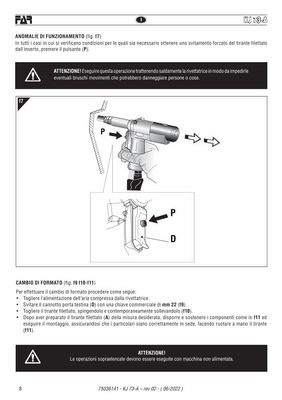
ANOMALIE DI FUNZIONAMENTO (fig. f7)In tutti i casi in cui si verificano condizioni per le quali sia necessario ottenere uno svitamento forzato del tirante filettato dall'inserto, premere il pulsante (P).
ATTENZIONE! Eseguire questa operazione trattenendo saldamente la rivettatrice in modo da impedirle eventuali bruschi movimenti che potrebbero danneggiare persone o cose.
f7
CAMBIO DI FORMATO (fig. f9 f10-f11)
Per effettuare il cambio di formato procedere come segue:• Togliere l’alimentazione dell’aria compressa dalla rivettatrice.• Svitare il cannotto porta testina (O) con una chiave commerciale di mm 22 (f9).• Togliere il tirante filettato, spingendolo e contemporaneamente sollevandolo (f10).• Dopo aver preparato il tirante filettato (A) della misura desiderata, disporre e sostenere i componenti come in f11 ed
eseguire il montaggio, assicurandosi che i particolari siano correttamente in sede, facendo ruotare a mano il tirante (f11).
ATTENZIONE!Le operazioni sopraelencate devono essere eseguite con macchina non alimentata.

9
IKJ 73-A
75036141 - KJ 73-A – rev 02 - ( 06-2022 )
22 mm
O
f9 f11
f10ATTENZIONE!• Nel componente (R) il lato da inserire nella testa tirante
è calamitato per evitarne la caduta accidentale nelle operazioni di cambio formato.
• Avvitare il cannotto porta testina (O) con una chiave commerciale di mm 22 e serrare correttamente.
ATTENZIONE!Le operazioni sopraelencate devono essere
eseguite con macchina non alimentata.

I KJ 73-A
10 75036141 - KJ 73-A – rev 02 - ( 06-2022 )
f13
f14
f12
22 mm
C
B
ATTENZIONE!Le operazioni sopraelencate devono essere eseguite con macchina non alimentata.
REGOLAZIONE DEL GRUPPO TIRANTE TESTINA(fig. f12-f13-f14)Al variare della lunghezza dell’inserto da serrare occorre regolare la posizione della testina (B) rispetto al tirante filettato (A).Togliere l’alimentazione dell’aria compressa dalla rivettatrice.Avvitare manualmente un inserto della lunghezza desiderata sul tirante filettato fino a che la testa dell’inserto vada in battuta con la testina (B) della rivettatrice. La testina (B) è regolata correttamente se il tirante filettato fuoriesce per circa 2 mm dall’inserto avvitato su di esso. In caso contrario sbloccare la ghiera (C) mediante una chiave commerciale di mm 22 quindi avvitare o svitare la testina (B) fino a trovare la giusta posizione, al termine bloccare la ghiera (C).
A
B C2 mm

11
IKJ 73-A
75036141 - KJ 73-A – rev 02 - ( 06-2022 )
f15
19 mm
H
I
M
KJ 73-A
ATTENZIONE! Non schiacciare o tagliare i tubi che collegano la rivettatrice al booster.Si raccomanda l’uso di olio HLP 32 cSt o simili.
RABBOCCO OLIO NEL CIRCUITO OLEODINAMICO (fig. f15)Verificare periodicamente (15000 cicli) che il livello dell’olio non scenda mai al di sotto dei 3/4 indicati dall’apposito segnalatore (I).Nel caso si rendesse necessario, immettere olio idraulico HLP 32 CST.ATTENZIONE ! Nel caso questa operazione non venga effettuata, si potrà riscontrare nel tempo, un calo di corsa della rivettatrice, che andrà accentuandosi fino a comprometterne il funzionamento. Occorrerà pertanto eliminare la presenza d’aria all’interno del circuito oleodinamico e ripristinarne la corretta quantità di olio. Procedere quindi come segue: con macchina non alimentata ruotare il pomello (M) verso il segno “+” sino al finecorsa, togliere il tappo (H) servendosi di una chiave di mm 19.Con macchina alimentata rabboccare con olio, eseguire alcuni cicli di rivettatura rabboccando olio, mantenendo l’impugnatura bassa rispetto al Booster come da figura (f15). Ripetere l’operazione fino al raggiungimento della corsa come da figura (f16).Il rabbocco si considera completato quando il livello dell’olio si stabilizza con il bordo del foro filettato. Rimontare quindi il tappo (H). Èestremamenteimportanteattenersialleistruzionisopraindicateedeffettuareleoperazionidirabboccooliomunitidiguanti.L’oliofuoriuscitodurante le operazioni indicate, dovrà essere raccolto in appositi recipienti ed affidato successivamente ad una ditta autorizzata per lo smaltimento del rifiuto.

I KJ 73-A
12 75036141 - KJ 73-A – rev 02 - ( 06-2022 )
MANUTENZIONEManutenzione giornaliera- Controllare che il tirante filettato non sia danneggiato.- Controllare il sistema di alimentazione dell’aria compressa.- Controllare che la corsa dell’attrezzo sia adatta per inserire l’inserto selezionato (vedere le istruzioni relative alla regolazione
della corsa, riportate a pagina 6).- Controllare che non vi siano perdite di aria o di olio. In tal caso sostituire eventuali raccordi o guarnizioni danneggiate.- Controllarechelapressionedialimentazionedell’ariacompressasiadimax 7 bar.
Manutenzione settimanale- Controllare il livello dell’olio verificando che la corsa della rivettatrice soddisfi i requisiti minimi di 10 mm senza inserto
applicato (fig. f16). Se la verifica non soddisfa i requisiti minimi ripetere la procedura di rabbocco olio (fig. f15).
Revisione della rivettatriceÈconsigliabileprocedereadunarevisionecompletadellarivettatricedopo600.000 cicli oppure ogni anno.In questo caso rivolgersi esclusivamente a centri autorizzati dalla FAR S.r.l.
SMALTIMENTO DELLA RIVETTATRICEPer lo smaltimento della rivettatrice attenersi alle prescrizioni imposte dalle leggi nazionali.Dopo aver scollegato la macchina dall’impianto pneumatico, procedere allo smontaggio dei vari componenti suddividendoli in funzione della loro tipologia: acciaio, alluminio, materiale plastico, ecc.Procedere quindi alla rottamazione nel rispetto delle leggi vigenti.
f16
10 mm ( + 0.2 )0

13
GBKJ 73-A
75036141 - KJ 73-A – rev 02 - ( 06-2022 )
INSTRUCTIONS FOR USE I
INDEX
GUARANTEE .......................................................................13SAFETY MEASURES AND REQUIREMENTS .......................13TOOL IDENTIFICATION .......................................................14GENERAL NOTES AND USE ................................................14MAIN COMPONENTS ..........................................................14TECHNICAL DATA ...............................................................14AIR FEED .............................................................................15PRELIMINARY OPERATIONS ..............................................15PLACING OF THE INSERT ...................................................16WORKING PROBLEMS .......................................................17CHANGE OF SIZE ............................................................... 17ADJUSTMENT OF TIE-ROD/HEAD UNIT ............................. 19TOOPING UP THE OIL-DYNAMIC CIRCUIT .........................20MAINTENANCE .................................................................. 21DISPOSAL OF THE RIVETING TOOL ...................................21
CAUTION!!!All the operations must be done in conformity with the safety requirements, in order to avoid any consequence for your and other people security and to allow the best tool work way.
•Readtheinstructionscarefullybeforeusingthetool.• For all maintenance and/or repairs please contact
FAR s.r.l. authorized service centers and use only original spare parts. FAR s.r.l. may not be held liable for damages from defective parts caused by failure to observe what mentioned above (EEC directive 85/374).
THE LIST OF THE SERVICE CENTRES IS AVAILABLE ON OUR WEBSITE
http://www.far.bo.it ( Organization )
•Thetoolmustbeusedonlybyexpertworkers.
GUARANTEE
FAR riveting tools are covered by a 12-month warranty. The tool warranty period starts on the date of delivery to the buyer, as specified in the relevant document. The warranty covers the user/buyer provided that the tool is purchased through an authorized dealer and only if it is used for the purposes for which it was conceived. The warranty shall not be valid if the tool is not used or maintained as specified in the instruction and maintenance handbook. In the event of defects or failures, FAR S.r.l. shall undertake solely to repair and/or replace the components it judges to be faulty.
• Aprotectivevisorandglovesmustbeputonwhenusingthetool.
• Useequipmentrecommendedinthemaintenancechaptertodo any maintenance and/or regulation of the tool.
• For topping up the oil, we suggest using only fluids inaccordance with the features specified in this working book.
• Ifanydropofoil touchesyourskin,youmustwashwithwater and alkaline soap.
• Thetoolcanbecarriedandwesuggestputtingitintoitsboxafter using.
• Thetoolneedsathoroughsix-monthlyoverhaul.• Therearenospecialrequirementsforstorage.• Repairingandcleaningoperationsmustbedonewhenthe
tool is not fed.• Asafetybalancerissuggestedwhenitispossible.• IftheA-weightedemissionsoundpressurelevelismorethan
70 dB (A), you must use some hearing protections (anti-noise headset, etc.).
• Theworkbenchandtheworksurfacemustbealwayscleanand tidy. The untidy can cause damages to people.
• Donotallowunauthorizedpersonstousetheworkingtools.• Makeyousurethatthecompressedairfeedinghoseshave
the correct size to be used. • Donotcarrytheconnectedtoolbypullingthehose.Thehole
must be far from any heating sources or from cutting parts.• Keepthetoolsingoodconditions;donotremoveeithersafety
parts or silencers.• Afterrepairingand/oradjusting,makesureyouhavealready
removed the adjusting spanners.• Beforedisconnectingthecompressedairhosefromthetool
make sure that there is no pressure in the hose.• Theseinstructionsmustbecarefullyfollowed.• Donotusetherivetingtoolinthecaseofvisibledamage.
SAFETY MEASURES AND REQUIREMENTS

GB
14
KJ 73-A
75036141 - KJ 73-A – rev 02 - ( 06-2022 )
Company name and address Designation of the tool
Serial number
KJ 73-A
KJ 73-A
KJ 73-A
17”
8”
5”
11,6”*
Ø 1,97”
4,8”*
Ø 1,12”
A B C
I
E F GD
L
M
N
TOOL IDENTIFICATIONThe riveting tool KJ73-A is identified from a marking that shows company name and address of manufacturer, designation of the tool, CE. Always refer to the information on the riveting tool when requesting technical service.
TECHNICAL DATA• Workingpressure ........................................ 87 ÷ 101.5 psi• Min.int.diam.ofthecompressedairfeedinghose .0.315 "• Maxfreeairconsumptionpercycle ......................5.492 in³ • Maximumforce ........................................87 psi - 7.119 lbfWEIGHT:•Gun ............................................................................. 3.3 lb• Weight ..................................................................... 19.1 lb• Workingtemperature .................................... -23°F/+122°F• Rootmeansquareintotalaccelerationfrequency(Ac)to which the arms are subjected .......................... < 98.42 ips² • A-weightedemissionsoundpressurelevel .............. 74 dBA• PeakC-weightedinstantaneoussoundpressure . <130 dBC• A-weightedsoundpower ........................................ 85 dBA
MAIN COMPONENTS
A) ..................................................................Threaded tie rodB) ....................................................................................HeadC) ......................................................Ring-nut clamping headD) ..............................................................Tube carrying headE) ............................................................Balancer connectionF) ........................................................................Oil tank plugG) ................................................................ Pneumatic motorI) ...............................................................Unscrewing buttonL) ............................................................Control push-buttonM) ........................................................Stroke-adjusting knobN) ................................................ Compressed air connection
* with 3/8"-16 UNC tie rod
GENERAL NOTES AND USEThe tool can be employed only for threaded inserts 6-32 ÷ ÷ 1/2"-13 UNC diameter.The KJ73-A hydropneumatic system assures more power than the pneumatic system used for other models. That means a reduction in the problems due to the wear and tear of the components, therefore, there will be an increase in reliability. The technical solutions adopted reduce the dimensions and the weight of the tool, which is very handy for these reasons. The possibilities of leakage from the oil-dynamic system, are eliminated by some sealed gaskets, which solve this problem.

15
GBKJ 73-A
75036141 - KJ 73-A – rev 02 - ( 06-2022 )
f1
f3
B
A
M
15 0
FRL UNIT ATTENTION! The incorrect adjustment of the riveting tool can cause a bad clamping of the inserts and a possible break of the tie rod!
PRELIMINARY OPERATIONS (fig. f2-f3)Check that the threaded tie rod (A) and head (B) couple assembled on the riveting tool is suitable to the size of the insert to clamp; otherwise change the size (page 34). The tie-rod (A)/head (B) unit assembled on this riveting tool, corresponds to a 3/8"-16 UNC thread.Before using the riveting tool and after each change of size, the stroke should be adjusted according to the dimensions, type of the insert and thickness of the material to clamp. Before carrying out this operation rotate the knob (M) according to the direction of the arrow, (+) for increasing the stroke and (-) for decreasing it. Increasing the stroke - rotation of knob (M) - in the direction indicated with the symbol (+), the distance “h” (page 28) decreases increasing the clamping action. NOTE: Before the definitive placing of the insert, its clamping on the thicknesses involved should be checked, carrying out other adjustments, as shown at page 39 (the specified adjustments are just an indication, it is advisable to see the technical data of the inserts used).
AIR FEED (fig. f1)The air feed must be free from foreign bodies and humidity in order to protect the device from premature wear and tear of the components in movement, therefore we suggest to use a lubricator group for compressed air.
118" Max

GB
16
KJ 73-A
75036141 - KJ 73-A – rev 02 - ( 06-2022 )
f4
f5
f6
PLACING OF THE INSERT (fig. f4-f5-f6)Check that the threaded tie rod (A) and head (B) couple assembled on the riveting tool is suitable to the size of the insert to be used.Adjust the stroke as indicated (fig. f3).Introduce the insert on the tie rod (A) and push slightly on it as indicated in figure f4, so as to make it clamp automatically on the threaded tie rod. Make sure that the insert head touches the head (B) checking that the tie rod (A) comes out of 0.078" from the insert.In case of further adjustments of the tie rod (A) follow the instructions of page 19.It is now possible to place the insert pushing the button (D) (fig.f5-f7) until the insert is completely pulled, and push the button (P) to release the tie rod (fig.f7).For a correct placing and right working of the machine, the inserts to be used should be properly cleaned.
Note: According to the desired clamping, carry out other adjustments of the riveting tool stroke, rotating the knob (M) (fig. f3-f6), if necessary.
Insufficient deformation = the insert could rotate inside the housing compromising its use and resistance.
Excessive deformation = possible damages of the insert and tie rod (A) with eventual breaks of both components.
BA
D
M
0.078"
17
GBKJ 73-A
75036141 - KJ 73-A – rev 02 - ( 06-2022 )
P
P
D
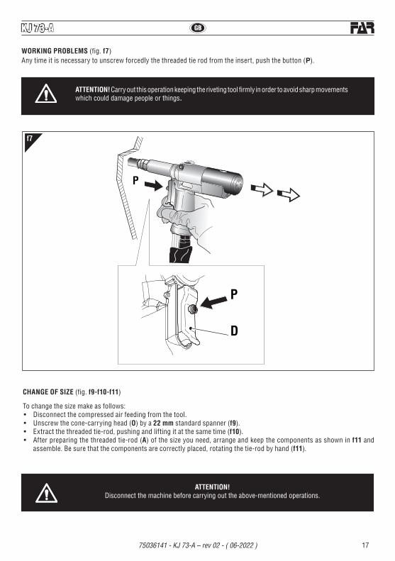
WORKING PROBLEMS (fig. f7)Any time it is necessary to unscrew forcedly the threaded tie rod from the insert, push the button (P).
ATTENTION! Carry out this operation keeping the riveting tool firmly in order to avoid sharp movements which could damage people or things.
f7
CHANGE OF SIZE (fig. f9-f10-f11)
To change the size make as follows:• Disconnect the compressed air feeding from the tool.• Unscrew the cone-carrying head (O) by a 22 mm standard spanner (f9).• Extractthethreadedtie-rod,pushingandliftingitatthesametime(f10).• After preparing the threaded tie-rod (A) of the size you need, arrange and keep the components as shown in f11 and
assemble. Be sure that the components are correctly placed, rotating the tie-rod by hand (f11).
ATTENTION! Disconnect the machine before carrying out the above-mentioned operations.

GB
18
KJ 73-A
75036141 - KJ 73-A – rev 02 - ( 06-2022 )
f9 f11
f10
22 mm
O
ATTENTION!• The side of the component (R) to be entered in the head
of the tie-rod is provided of a magnet to avoid accidental fall during the operations of change of size.
• Screw the cone carrying heads (O) by a 22 mm standard spanner and clamp correctly.
ATTENTION! Disconnect the machine before carrying out
the above-mentioned operations.

19
GBKJ 73-A
75036141 - KJ 73-A – rev 02 - ( 06-2022 )
f13
f14
f12
22 mm
C
B
ATTENTION! Disconnect the machine before carrying out the above-mentioned operations.
ADJUSTMENT OF TIE-ROD/HEAD UNIT (fig. f12-f13-f14)Changing the length of the insert to clamp, the position of the head (B) compared to the threaded tie rod (A) should be adjusted.Disconnect the compressed air feeding from the tool.Screw an insert of the desired length on the threaded tie rod manually until the insert head touches the riveting tool head (B). The head is adjusted correctly if the threaded tie rod comes out of the insert screwed on it of about 0.078". Otherwise unblock the ring nut (C) with a 22 mm standard spanner then screw or unscrew the head (B) up to the right position, and block the ring nut (C).
A
B C0.078"

GB
20
KJ 73-A
75036141 - KJ 73-A – rev 02 - ( 06-2022 )
f15
19 mm
H
I
M
KJ 73-A
ATTENTION! Do not crush or cut the pipes that connect the riveter to the booster.We recommend to use oil HLP 32 cSt or similars.
TOPPING UP THE OIL-DYNAMIC CIRCUIT (fig. f15)Periodically check (15,000 cycles) that the oil level never falls below the 3/4 reported by the appropriate indicator (I).If necessary, add HLP 32 CST hydraulic oil.WARNING ! If this operation is not carried out, it will be possible to notice over time a drop in the riveting tool stroke, which will increase until it compromises its functioning. Therefore, it will be necessary to eliminate the air inside the hydraulic circuit and restore the correct amount of oil. Then proceed as follows: with machine with air supply off, turn the knob (M) as much as possible towards the "+" sign, remove the cap (H) with a 19 mm wrench. With the air supply on, top up with oil, perform a few riveting cycles adding oil while keeping the handle down with respect to the Booster, as shown in the picture 15.Repeat the operation until reaching the stroke as shown in the picture 16.Topping up is completed when the oil level is stable and touches the lip of the threaded hole. Fit again the cap (H).Itisextremelyimportanttofollowtheinstructionsaboveandcarryouttheoilrefillingoperationswithgloves.Theoilspilledduring the indicated operations must be collected in special containers and subsequently entrusted to an authorized company for the disposal of the waste.

21
GBKJ 73-A
75036141 - KJ 73-A – rev 02 - ( 06-2022 )
MAINTENANCEDaily maintenance- Check that the threaded tie rod is not damaged.- Check the supply system of the compressed air.- Check that the stroke of the tool is suitable for the selected insert to clamp (see the pertaining instructions for adjusting
the stroke, indicated at page 15).- Check that there are neither air nor oil leakages. In this case replace possible damaged connectors or seals.- Checkthatthesupplypressureofthecompressedairdoesnotexceed 101.5 psi.
Weekly maintenance- Check the oil level by verifying that the riveter stroke meets the minimum requirements of .393" without insert inserted
(fig. f16). If the check does not meet the minimum requirements, repeat the oil filling procedure (fig. f15).
Overhaul of the riveting toolIt is advisable to carry out a complete overhaul of the riveting tool after 600,000 cycles or every year.In this case apply only to centres authorized by FAR S.r.l.
DISPOSAL OF THE RIVETING TOOLFollow the prescriptions of the national laws for disposing of the riveting tool.After disconnecting the tool from the pneumatic system, disassemble and split all the components according to the material: steel, aluminium, plastic material, etc.Then proceed to scrap the materials in accordance with current laws.Procedere quindi alla rottamazione nel rispetto delle leggi vigenti.
f16
.393" (+ 0.008 ) 0

KJ 73-A
75036141 - KJ 73-A – rev 02 - ( 06-2022 )
I
22
Tav. 1/4N° COD. Qt. DESCRIZIONE KIT
01 71345401 1 Testina 3/8"-16 UNC 3/8"-24 UNF02 71345409 1 Tirante 3/8"-16 UNC03 72A00105 8 Gruppo esagonale M 1004 71345402 1 Testina 1/2"-13 UNC05 71345410 1 Tirante 1/2"-13 UNC06 71345400 1 Testina 5/16"-18 UNC 5/16"-24 UNF07 71345408 1 Tirante 5/16"-18 UNC80 71345399 1 Testina 1/4"-20 UNC 1/4"-28 UNF09 71345407 1 Tirante 1/4"-20 UNC10 71345398 2 Testina 10-32 UNF 10-24 UNC11 71345405 1 Tirante 10-24 UNC12 71345397 1 Testina 8-32 UNC13 71345404 1 Tirante 8-32 UNC14 71345406 1 Tirante 10-32 UNF15 71345396 1 Testina 6-32 UNC16 71345403 1 Tirante 6-32 UNC
17A 711062 1 Guarnizione OR 2-126 A18 71345264 1 Pistone oleodinamico19 71345260 1 Ghiera
20A 710244 1 Guarnizione OR 2-130 A21A 713275 1 Guarnizione OR 2-122 A22 72A00125 1 Motore pneumatico F00123 713170 6 Ghiera24 71345517 1 Cannotto25 71345515 1 Cannotto porta tirante26 72A00107 1 Gruppo trascinamento27 71345516 1 Molla28 71345263 1 DadoM16x1
29A 710925 1 Guarnizione OR 027 A30 71345261 1 Flangia
31A 71C00295 1 Anello Parbak 8-028 A32A 71C00296 1 Guarnizione OR 5-670 A33 71345258 1 Camicia
34C 713389 1 Guarnizione 157118-B / NEO C
Tav. 2/4N° COD. Qt. DESCRIZIONE KIT
41 713405 1 ViteTBCEM6x10ISO738042 710555 1 Rondella 400-004-4490
43C 711722 1 Guarnizione B-094063-B / NEI C44 713402 1 Anello seeger JV 2545 713308 2 Tappo
46G 71345174 1 Otturatore Destro G47A 710258 1 Guarnizione OR 5-612 A48A 71C00529 1 Guarnizione XR 008 PP180 B A49 713406 2 ViteTSCEM4x25UNI593350 72000359 1 Protezione motorino51 716198 1 ViteTCCEM4x12UNI5931
52G 713158 1 Otturatore G53 72A00188 1 Gruppo valvola controllo Motorino
54A 713390 2 Guarnizione OR 2-007 A55 72A00007 1 Raccordo aria56 716150 2 ViteTSCEM4x12UNI5933
57AHI 710376 2 Guarnizione OR 2-009 AHI58A 710528 1 Guarnizione OR 008 A59A 713394 1 Guarnizione OR 2-106 A60 71345649 1 Pulsante di svitamento61 713401 1 RullinoNRBø3x19.862 71345648 1 Pulsante
63A 710385 2 Guarnizione OR 2-006 A64A 710572 1 Guarnizione OR 2-120 A65 71346458 1 Raccordo finale impugnatura
66A 710914 1 Guarnizione OR 2-116 A67 71346457 1 Raccordo
68A 711732 1 Guarnizione OR 2-118 A69 711039 1 Raccordo girevole
70A 711061 3 Guarnizione OR 5-614 A71 711038 1 Raccordo fisso
72A 710921 2 Guarnizione OR 2-115 A73 711036 1 Riduzione74 71C01554 1 Tubo alta pressione mt 1,8575 711084 2 Raccordo 6700 - ø 576 731059 2 TuboRilsanø5x3,5x3000
77AHI 710918 2 Guarnizione OR 2-005 AHI78AHI 711338 2 Guarnizione OR 2-003 AHI79AHI 716060 4 Guarnizione OR 2-010 AHI
80 710969 1 Contenitore olio81 712225 1 Chiave a brugola 4 mm
KIT KITA 74000102 Kit PneumaticoKITB 74000027 Kit Contenitore tiranteKITC 74000112 Kit Oleodinamico
KIT Indica che il particolare viene venduto in Kit composti da particolari diversi in quantità diverse.
KIT KITD 74000041 Kit Cilindro OleodinamicoKITE 74000021 Kit SilenziatoreKITF 74000029 Kit AstaKITG 74000073 Gruppo otturatoreKITH 74000033 Kit Pistone superioreKITI 74000034 Kit Pistone inferioreKITL 74000025 Kit GancioKITM 74000053 Kit ImpugnaturaKITZ 74000035 Kit Piastra di ritegno

KJ 73-A
75036141 - KJ 73-A – rev 02 - ( 06-2022 )
I
23
Tav. 3/4N° COD. Qt. DESCRIZIONE KIT
01 71346475 1 Testata cilindro posteriore02 71345603 1 Testata cilindro anteriore03 711665 1 Tappo valvola04 71C00694 2 Raccordo 6510 - ø 5 - 1/8"05 711994 2 Raccordo 6510 - ø 8 - 1/4"06 71C01563 2 Silenziatore Art.527 - SPPE 1/4"07 71C00179 3 Raccordo S 2020 - 1/4"- 1/4"08 710841 1 Spoletta09 710822 1 Pistoncino valvola
10S 710258 1 Guarnizione OR 5-612 S11S 710922 2 Guarnizione OR 018 S12 712268 1 Tappo guida molla13 712061 1 Rondella
14S 710916 1 Guarnizione OR 2-015 S15S 710528 1 Guarnizione OR 008 S16 71345599 1 Piastra forata17 711663 1 Tappo 2611-1/4"18 71345165 1 Cannotto Booster19 71345440 1 Pistone pneumatico20 716161 1 Anello di arresto guarnizione21 71346399 1 Ammortizzatore
22S 710595 1 Guarnizione OR 2-341 S23S 71C00402 2 Guarnizione OR 2-239 S24 712050 2 ViteSTCEM8x8UNI592325 716180 1 Valvola VSC 544 - 1/4"26 711662 1 Livello olio HFE.927 71345598 4 Tirante M 828 712793 4 ViteTCCEM6x18UNI593129 71345596 1 Camicia30 712585 8 Rosetta ø 8 UNI 659231 711825 1 Raccordo NPT 130032 711823 1 Raccordo NV 1/4" NPT-F33 71345601 1 Piede34 710623 6 Dado M 6 UNI 747335 711829 4 ViteTSCEM6x20UNI593336 71346398 1 Guida raccordo37 71345600 1 Bussola per guarnizione38 710905 1 Anello Seeger 11 UNI 743739 71345602 2 Piastrina angolare40 71C00737 1 Maniglia M 943-144 B M541 716143 2 ViteTCCEM5x10UNI593142 71C00732 2 ViteSTCEM6x20UNI592343 71C00703 8 Dado M 8 UNI 572144 712824 1 Colonnetta 2525 -1/4" H 27
45SHI 716060 1 Guarnizione OR 2-010 SHI46 716356 1 Raccordo 6525 - ø 8 - 1/4"47 71C00373 1 Anello di tenuta 2661-3/8"48 711998 1 Tappo 2611-3/8"49 71C00216 1 Anello di tenuta 2661-1/4"
50RS 710923 1 Guarnizione OR 012 RS51 71C01635 1 DadoM10x1,5DIN6923
52S 710003 1 Guarnizione OR 5-052 S53NS 711982 1 Guarnizione OR 2-120 NS54NS 711661 1 Guarnizione OR 2-135 NS55NS 716164 1 Anello Sealing WRI 14 NS
KIT Indica che il particolare viene venduto in Kit composti da particolari diversi in quantità diverse.
Tav. 3/4N° COD. Qt. DESCRIZIONE KIT
56NS 711341 1 Guarnizione TS-14-22-5,8 / L NS57NS 710579 1 Guarnizione OR 2-113 NS58PS 710823 3 Gabbia PS59PS 710921 3 Guarnizione OR 2-115 PS60NS 710375 1 Guarnizione OR 2-131 NS61NS 716162 1 Anello Sealing RSS 14-22/1 NS
62 712160 1 Guaina contenimento tubi63 711824 1 Raccordo NV 1/4" NPT-M
64P 711158 1 Molla P65P 710840 1 Distanziale valvola P66 71346459 1 Distanziale67 711067 2 Raccordo 6520 - ø 8 - 1/4"68 71C01562 1 Raccordo 6550 - ø 869 71346422 1 TuboRilsanø8x6x4570 71346421 2 TuboRilsanø8x6x3571 713322 1 Vite M 572 713318 1 Albero trascinatore73 713321 1 Vite 2 principi74 71346461 1 Raccordo flangiato
75S 71C00697 1 Guarnizione OR 5-256 S76 716412 1 ViteTSCEM4x14UNI593377 713199 1 Molla78 713403 1 Sfera ø 5,579 71346460 1 Disco80 713316 1 Ghiera
81S 713400 1 Guarnizione OR 5-616 S82 713194 1 Pomello83 71C01636 4 Vite TSEIM3x12UNI593384 712575 1 ViteTSCEM5x12UNI5933
KIT KITN 74000047 Kit Raccordo anterioreKITP 740840 Kit Distanziale valvolaKITR 74000103 Kit SteloKITS 74000104 Kit Pneumatico
Tav. 4/401 71C00764 1 Cuscinetto 6180102 71345645 1 Portasatelliti estremo03 71345644 3 Satellite04 71345643 1 Corona05 71345642 1 Rondella06 71C00763 1 Cuscinetto AY7-ZZ07 71345640 1 Raccordo08 71C00761 2 Spinaelasticaø1,5x10UNI687509 71345639 5 Aletta10 71345638 1 Rotore11 71345637 1 Corpo esterno12 71345641 1 Piattello posteriore13 713037 1 Rullinoø2x9,814 71C00762 1 Cuscinetto 695-ZZA 72A00125 Motore pneumatico F001

KJ 73-A
75036141 - KJ 73-A – rev 02 - ( 06-2022 )
GB
24
Tab. 1/4No. CODE Q.ty DESCRIPTION KIT
01 71345401 1 Head 3/8"-16 UNC 3/8"-24 UNF02 71345409 1 Tie rod 3/8"-16 UNC03 72A00105 8 Hexagonalunitfortie-rodM1004 71345402 1 Head 1/2"-13 UNC05 71345410 1 Tie rod 1/2"-13 UNC06 71345400 1 Head 5/16"-18 UNC 5/16"-24 UNF07 71345408 1 Tie rod 5/16"-18 UNC80 71345399 1 Head 1/4"-20 UNC 1/4"-28 UNF09 71345407 1 Tie rod 1/4"-20 UNC10 71345398 2 Head 10-32 UNF 10-24 UNC11 71345405 1 Tie rod 10-24 UNC12 71345397 1 Head 8-32 UNC13 71345404 1 Tie rod 8-32 UNC14 71345406 1 Tie rod 10-32 UNF15 71345396 1 Head 6-32 UNC16 71345403 1 Tie rod 6-32 UNC
17A 711062 1 Gasket OR 2-126 A18 71345264 1 Hydraulic piston19 71345260 1 Ring nut
20A 710244 1 Gasket OR 2-130 A21A 713275 1 Gasket OR 2-122 A22 72A00125 1 Pneumatic Motor F00123 713170 6 Ring nut24 71345517 1 Sleeve25 71345515 1 Sleeve carrying tie rod26 72A00107 1 Driving unit27 71345516 1 Spring28 71345263 1 NutM16x1
29A 710925 1 Gasket OR 027 A30 71345261 1 Flange
31A 71C00295 1 Ring Parbak 8-028 A32A 71C00296 1 Gasket OR 5-670 A33 71345258 1 Jacket
34C 713389 1 Gasket 157118-B / NEO C
Tab. 2/4No. CODE Q.ty DESCRIPTION KIT
41 713405 1 ScrewTBCEM6x10ISO738042 710555 1 Washer 400-004-4490
43C 711722 1 Gasket B-094063-B / NEI C44 713402 1 Seeger ring JV 2545 713308 2 Cap
46G 71345174 1 Right spear valve G47A 710258 1 Gasket OR 5-612 A48A 71C00529 1 Gasket XR 008 PP180 B A49 713406 2 ScrewTSCEM4x25UNI593350 72000359 1 Fender motor51 716198 1 ScrewTCCEM4x12UNI5931
52G 713158 1 Obturator G53 72A00188 1 Valve unit for motor control
54A 713390 2 Gasket OR 2-007 A55 72A00007 1 Air connector56 716150 2 ScrewTSCEM4x12UNI5933
57AHI 710376 2 Gasket OR 2-009 AHI58A 710528 1 Gasket OR 008 A59A 713394 1 Gasket OR 2-106 A60 71345649 1 Unscrewing button61 713401 1 PinNRBø3x19.862 71345648 1 Push-button
63A 710385 2 Gasket OR 2-006 A64A 710572 1 Gasket OR 2-120 A65 71346458 1 Ending handgrip connector
66A 710914 1 Gasket OR 2-116 A67 71346457 1 Connector
68A 711732 1 Gasket OR 2-118 A69 711039 1 Rotating connector
70A 711061 3 Gasket OR 5-614 A71 711038 1 Fixedconnector
72A 710921 2 Gasket OR 2-115 A73 711036 1 Reduction74 71C01554 1 High pressure tube mt 1,8575 711084 2 Connector 6700 - ø 576 731059 2 Rilsantubeø5x3,5x3000
77AHI 710918 2 Gasket OR 2-005 AHI78AHI 711338 2 Gasket OR 2-003 AHI79AHI 716060 4 Gasket OR 2-010 AHI
80 710969 1 Oil container81 712225 1 Wrench 4 mm
KIT KITA 74000102 Pneumatic kitKITB 74000027 Tie rod contanier kitKITC 74000112 Oil-dynamic kit
KIT It indicates that the part is sold in kits consisting of different parts in different quantities.
KIT KITD 74000041 Oil-dynamic cylinder kitKITE 74000021 Silencer kitKITF 74000029 Rod kitKITG 74000073 Spear valve unitKITH 74000033 Upper piston kitKITI 74000034 Lower piston kitKITL 74000025 Hook kitKITM 74000053 Handgrip kitKITZ 74000035 Retaining plate kit

KJ 73-A
75036141 - KJ 73-A – rev 02 - ( 06-2022 )
GB
25
Tab. 3/4No. CODE Q.ty DESCRIPTION KIT
01 71346475 1 Back cylinder head02 71345603 1 Front cylinder head03 711665 1 Valve cap04 71C00694 2 Connector 6510 - ø 5 - 1/8"05 711994 2 Connector 6510 - ø 8 - 1/4""06 712343 2 Silencer 2 SEM 1/4" M07 71C00179 3 Connector S 2020 - 1/4"- 1/4"08 710841 1 Valve09 710822 1 Valve piston
10S 710258 1 Gasket OR 5-612 S11S 710922 2 Gasket OR 018 S12 712268 1 Spring guide plug13 712061 1 Washer
14S 710916 1 Gasket OR 2-015 S15S 710528 1 Gasket OR 008 S16 71345599 1 Drilled plate17 711663 1 Cap 2611-1/4"18 71345165 1 Booster sleeve19 71345440 1 Pneumatic piston20 716161 1 Stop ring21 71346399 1 Shock absorber
22S 710595 1 Gasket OR 2-341 S23S 71C00402 2 Gasket OR 2-239 S24 712050 2 ScrewSTCEM8x8UNI592325 716180 1 Valve VSC 544 - 1/4"26 711662 1 Oil level HFE.927 71345598 4 Tie rod M 828 712793 4 ScrewTCCEM6x18UNI593129 71345596 1 Jacket30 712585 8 Washer ø 8 UNI 659231 711825 1 Connector NPT 130032 711823 1 Connector NV 1/4" NPT-F33 71345601 1 Foot34 710623 6 Nut M 6 UNI 747335 711829 4 ScrewTSCEM6x20UNI593336 71346398 1 Pilot connector37 71345600 1 Sleeving gasket38 710905 1 Seeger ring 11 UNI 743739 71345602 2 Angle plate40 71C00737 1 Handle M 943-144 B M541 716143 2 ScrewTCCEM5x10UNI593142 71C00732 2 ScrewSTCEM6x20UNI592343 71C00703 8 Nut M 8 UNI 572144 712824 1 Stud bolt 2525 -1/4" H 27
45SHI 716060 1 Gasket OR 2-010 SHI46 716356 1 Connector 6525 - ø 8 - 1/4"47 71C00373 1 O Ring 2661-3/8"48 711998 1 Cap 2611-3/8"49 71C00216 1 O Ring 2661-1/4"
50RS 710923 1 Gasket OR 012 RS51 71C01635 1 NutM10x1,5DIN6923
52S 710003 1 Gasket OR 5-052 S53NS 711982 1 Gasket OR 2-120 NS54NS 711661 1 Gasket OR 2-135 NS55NS 716164 1 Ring Sealing WRI 14 NS
KIT It indicates that the part is sold in kits consisting of different parts in different quantities.
Tab. 3/4No. CODE Q.ty DESCRIPTION KIT
56NS 711341 1 Gasket TS-14-22-5,8 / L NS57NS 710579 1 Gasket OR 2-113 NS58PS 710823 3 Cage PS59PS 710921 3 Gasket OR 2-115 PS60NS 710375 1 Gasket OR 2-131 NS61NS 716162 1 Ring Sealing RSS 14-22/1 NS
62 712160 1 Sheath63 711824 1 Connector NV 1/4" NPT-M
64P 711158 1 Spring P65P 710840 1 Valve spacer P66 71346459 1 Spacer67 711067 2 Connector 6520 - ø 8 - 1/4"68 71C01562 1 Connector 6550 - ø 869 71346422 1 Rilsantubeø8x6x4570 71346421 2 Rilsantubeø8x6x3571 713322 1 Screw M 572 713318 1 Driving shaft73 713321 1 Double-thread screw74 71346461 1 Flanged connector
75S 71C00697 1 Gasket OR 5-256 S76 716412 1 ScrewTSCEM4x14UNI593377 713199 1 Spring78 713403 1 Ball ø 5,579 71346460 1 Disc80 713316 1 Ring nut
81S 713400 1 Gasket OR 5-616 S82 713194 1 Knob83 71C01636 4 ScrewTSEIM3x12UNI593384 712575 1 ScrewTSCEM5x12UNI5933
KIT KITN 74000047 Front connector kitKITP 740840 Valve spacer kitKITR 74000103 Stem kitKITS 74000104 Pneumatic kit
Tab. 4/401 71C00764 1 Bearing 6180102 71345645 1 Gear cage03 71345644 3 Planetary gear04 71345643 1 Crown gear05 71345642 1 Washer06 71C00763 1 Bearing AY7-ZZ07 71345640 1 Connector08 71C00761 2 Springpinø1,5x10UNI687509 71345639 5 Vane10 71345638 1 Rotor11 71345637 1 Outside body12 71345641 1 Back cap13 713037 1 Pinø2x9,814 71C00762 1 Bearing 695-ZZA 72A00125 Pneumatic Motor F001

26
KJ 73-A
75036141 - KJ 73-A – rev 02 - ( 06-2022 )
PARTI DI RICAMBIO • SPARE PARTS
Tav.1/4•Tab.1/4
CA B
22
1918
20 A21 A
33 34 C 17 A
29 A
32 A31 A30
KIT A
KIT B
2 3
23
2526
27 28
24
KIT C
Tav. 3/4
1
11
13
14
4
10
6
8
5
7
9
1516
3
3
3
3
3
3
3
12
10

27
KJ 73-A
75036141 - KJ 73-A – rev 02 - ( 06-2022 )
PARTI DI RICAMBIO • SPARE PARTS
Tav.2/4•Tab.2/4
KIT H
KIT M
KIT I
49KIT E48 A
4546 G
55
54 A
KIT F
47 A
53
45
52 G
56
50
51KIT H
KIT Z61
KIT I
59 A
62
60
63 A
KIT M
64 A
65
67
69
71
73
74
57 A58 A
KIT F
KIT E
KIT G
KIT Z
KIT D
KIT L
41
42KIT L
44
66 A
68 A
72 A
70 A
75
76
CA B
Tav. 3/4
46
52
43 C
8180
KIT D
7978
KIT A
77
7978
KIT A
77
72 A

28
KJ 73-A
75036141 - KJ 73-A – rev 02 - ( 06-2022 )
PARTI DI RICAMBIO • SPARE PARTS
Tav.3/4•Tab.3/4
KIT S
KIT N
KIT P
KIT R
62
32
63
31
4330
26 2 47
48
1823 S
2060 N-S
61 N-S
2434
7067
21
KIT R
50 R-S
66
19
22 S
51 R
1
43 77 78
30
23 S
45 S71
72
74
7679
8082
83 84
73
2434
28
52 S
35
33 35
TAV. 2/4
CA
B
449 6
17
5
167
25
46 44 4
5
13
58 P
64 P
59 P-S65 P
8
938
123
14 S
10 S11 S
15 S
6697
6770
7
70
68
37
5354
55 56 5736
KIT N-S
4229
343940
41
42
34
39
27
75 S
81 S
KJ 73-A

29
KJ 73-A
75036141 - KJ 73-A – rev 02 - ( 06-2022 )
PARTI DI RICAMBIO • SPARE PARTS
Tav.4/4•Tab.4/4
1
6
11
8
12
13
14
7
8
9
10
2
3
4
5


SISTEMI DI FISSAGGIOFASTENING SYSTEMS • SYSTEMES DE FIXATION
VERBINDUNGSSYSTEME • SISTEMAS DE FIJACIONSYSTEMY MOCOWANIA • СИСТЕМЫ КРЕПЛЕНИЯ
www.far.bo.it
L’elenco dei centri di assistenza è disponibile sul Ns. sito web: http://www.far.bo.it ( Organizzazione )
The list of the service centres is available on our website http://www.far.bo.it ( Organization )
La liste des centres d’assistance est disponible sur notre site internet http://www.far.bo.it ( Organisation )
Die Liste der Reparaturservices ist verfügbar unter unserer Webseite http://www.far.bo.it ( Organisation )
La lista de los servicios postventa es disponible en nuestro sitio web http://www.far.bo.it ( Organización )
Lista punktów serwisowych jest dostępna na naszej stronie internetowej http://www.far.bo.it ( Organizacja )
Список сервисных центров приведен на нашем веб-сайте http://www.far.bo.it ( ОРГАНИЗАЦИЯ )
I
F
E
PL
RUS
GB
D
SEDE•HEADOFFICE•SIEGEHAUPTSITZ•SEDE
SIEDZIBA• ОФИСНЫЙ ЦЕНТР :S.r.l. Uninominale
40057 Quarto Inferiore - Bologna - Italy Via Giovanni XXIII, 2
Tel. +39 - 051 6009511UfficioVenditeFax+39-051767443
E-mail: [email protected]+39-051768284
E-mail:[email protected]
DEPOSITO•WAREHOUSE•DEPOTWARENLAGER•ALMACEN
ODDZIAŁ•СКЛАД :
20099 Sesto San Giovanni Milano
ItalyVia Archimede, 8
Tel. +39 - 02 2409634Fax+39-0226222279E-mail: [email protected]