Micro cam system driven by electrostatic comb-drive actuators based on SOI-MEMS technology
10
1 23 Microsystem Technologies Micro- and Nanosystems Information Storage and Processing Systems ISSN 0946-7076 Microsyst Technol DOI 10.1007/s00542-014-2086-y Micro cam system driven by electrostatic comb-drive actuators based on SOI-MEMS technology Phuc Hong Pham, Toan Khac Dinh, Lam Bao Dang, Khoa Tuan Nguyen & Dzung Viet Dao
-
Upload
independent -
Category
Documents
-
view
0 -
download
0
Transcript of Micro cam system driven by electrostatic comb-drive actuators based on SOI-MEMS technology

1 23
Microsystem TechnologiesMicro- and Nanosystems InformationStorage and Processing Systems ISSN 0946-7076 Microsyst TechnolDOI 10.1007/s00542-014-2086-y
Micro cam system driven by electrostaticcomb-drive actuators based on SOI-MEMStechnology
Phuc Hong Pham, Toan Khac Dinh, LamBao Dang, Khoa Tuan Nguyen & DzungViet Dao

1 23
Your article is protected by copyright and
all rights are held exclusively by Springer-
Verlag Berlin Heidelberg. This e-offprint is
for personal use only and shall not be self-
archived in electronic repositories. If you wish
to self-archive your article, please use the
accepted manuscript version for posting on
your own website. You may further deposit
the accepted manuscript version in any
repository, provided it is only made publicly
available 12 months after official publication
or later and provided acknowledgement is
given to the original source of publication
and a link is inserted to the published article
on Springer's website. The link must be
accompanied by the following text: "The final
publication is available at link.springer.com”.

1 3
Microsyst TechnolDOI 10.1007/s00542-014-2086-y
TechnIcal PaPer
Micro cam system driven by electrostatic comb‑drive actuators based on SOI‑MEMS technology
Phuc Hong Pham · Toan Khac Dinh · Lam Bao Dang · Khoa Tuan Nguyen · Dzung Viet Dao
received: 22 December 2013 / accepted: 14 January 2014 © Springer-Verlag Berlin heidelberg 2014
1 Introduction
MeMS (micro electro-mechanical system) technology has been researched and widely applied in the world since the 1970s. MeMS technology is developed from the Ic tech-nology, using semiconductor materials for the fabrication of typical products such as: micro sensors, micro actua-tors and other micro structures. MeMS devices have been applied more and more in almost every market field such as: telecommunications, automotive, aeronautical, military, consumer markets, etc. With the task of conversion and transmission of movement, the micro mechanisms (MMs) and micro motors play a vital role in the MeMS devices and make a principal difference between MeMS and tradi-tional microelectronic systems.
hayashi’s work (1994) in the 1990s pointed out the need for research and characterization of the MMs. at the same time, Mehregany and Tai (1991) designed and fab-ricated a number of common MMs such as four-bar link-age, gearing mechanisms and micro motors using surface-micromachined technology. chu et al. (2011) reported an electrothermal micro gripper using micro compliant link-ages in order to obtain larger gripping stroke. The counter meshing gear pair designed by Polosky et al. (1998) can generate discriminated motion. Fabricated with the same surface-micromachined technology, micro motors (Ste-phen et al. 2000; Tanner 2001; Sacks and Barnes 2001) used the ratchet mechanism in order to created unidirec-tional motion of a rotor from reciprocating motion of the ecas. a wedge stepping motor developed by allen and Schriner (1998) used a wedge mechanism, which oper-ated on the direct-contact sliding of inclined surfaces, to rotate the rotor. Sniegowski and Garcia combined the motion of two perpendicular sets of ecas to create a rotating motion of an output gear (Garcia and Sniegowski
Abstract This paper reports a design and fabrication pro-cess of a micro cam system (McS) with a flat-faced trans-lating follower. The cam rim with cover diameter of 2.4 mm is driven by four electrostatic comb-drive actuators (eca). reciprocating motion of the ecas is converted to unidi-rectional rotating movement of the outer cam rim through ratchet and anti-reverse mechanisms. The McS was fabri-cated by using SOI (silicon on insulator) wafer with 30 μm thick device layer, and only one mask. Driven by periodic voltage with different frequencies, the performance of the McS was successfully tested. In our experiment, when the system was run by the minimal driving voltage of 80 V, the obtained stroke of the follower was 160 μm. In addition, the system can run smoothly while applying the force of 31.3 μn on the follower. The McS can be applied in micro valve structures, in micro assembling systems, etc.
AbbreviationsDrIe Deep reactive ion-etchingeca electrostatic comb-drive actuatorIc Integrated circuitMeMS Micro electro-mechanical systemMM Micro mechanismMcS Micro cam systemMrM Micro rotational motorSOI Silicon on insulator
P. h. Pham · T. K. Dinh · l. B. Dang (*) · K. T. nguyen School of Mechanical engineering, hanoi University of Science and Technology, 1-Daicoviet, hanoi, Vietname-mail: [email protected]
D. V. Dao Queensland Micro and nanotechnology centre, Griffith University, Parklands Drive, Southport, QlD 4222, australia
Author's personal copy

Microsyst Technol
1 3
1995; Sniegowski and Garcia 1996). rogers (1998) went on to design a reduction gear unit. Most of those MMs and micro motors, which were made by the surface-microma-chined technology, face a number of setbacks as compli-cated fabrication process, sophisticated control system and limited power transmission ability because of a thin struc-ture thickness.
another way of movement generation in the micro motors is the inchworm motion. Kolesar (2004) used two sets of eight hot arm–cold arm actuators for push-ing and two sets of three hot arm–cold arm actuators for gripping a shuttle in order to create bi-directional lin-ear motion. Using a SOI wafer and bulk-micromachined technology, Yeh et al. (2002) arranged the ecas to clasp and push the rack, which is used as a rotor, to move lin-early in both directions. Kim et al. (2005) also used the SOI wafer to fabricate an inchworm motor with electro-static twisting micro actuators. Beside advantages such as high speed, acceptable driving voltage, those inchworm motors require a complex control unit and also have bulky dimension.
Pham et al. (2012) designed a micro rotational motor (MrM) using the ecas with curved electrodes and the ratchet mechanism to create unidirectional rotation of the rotor ring. Because of the fact that all actuators are arranged inside the rotor ring, the MrM has a relatively small size with 2.4 mm cover diameter. The MrM can also transmit a greater amount of power than the surface-micromachined motors mentioned above because of the thicker device
layer fabricated by bulk-micromachined technology with only one mask.
In this paper, based on the design of the original MrM in (Pham et al. 2012), the authors continuously develop the micro cam system (McS) with the flat-faced translating follower.
2 Configuration and working principle
Figure 1 shows the configuration of the McS containing four ecas, four anti-reverse mechanisms ③, the outer cam rim ⑤ and the flat-faced translating follower ⑥. each eca is connected to the movement-transmission mechanism ④.
When a periodic voltage is applied between fixed elec-trodes ① and movable structures ② of the eca, the movable part, i.e. the beam and movable comb fingers, will rotate clockwise around an elastic point ⑨ at the end of the eca beam under the influence of the tangential electrostatic force. Through movement-transmission mechanisms ④, a rotational movement of the ecas is transmitted to the outer cam rim ⑤ and makes it rotate in the same direction. When voltage decreases to zero, all movable structures will return to the initial position due to an elastic force. The anti-reverse mechanisms ③ help to prevent the cam rim from going back. The motion rule of the follower ⑥ is dependent on the cam rim profile. The springs ⑦ are con-nected to the follower in order to maintain contact between the follower and the cam rim ⑤.
Fig. 1 configuration of the McS
Author's personal copy

Microsyst Technol
1 3
The movement-transmission mechanism in driving and returning period is shown in Fig. 2. a spring ⑧ is used as a connector between the eca beam and the driving ratchet rack. In the driving period, the driving ratchet rack tightly engages with the outer cam rim and makes it rotate clock-wise (Fig. 2a). In the returning period, when the eca beam moves back to the initial position, the spring ⑧ will be compressed and there is free slide between the teeth of the ratchet rack and the cam rim (Fig. 2b).
3 Forces acting on the MCS
3.1 Driving period (when the driving ratchet pushes the outer ratchet rim)
3.1.1 Force analysis (without loading FL on the follower)
The driving force Fd from one eca acting on the cam rim ⑤ is similar to the driving force of the outer ring in the micro rotational motor (Pham et al. 2012) and determined by:
where Fes is an electrostatic force; Fel is an elastic force of beam (around the elastic point ⑨); Ff2 is a friction force between the driving ratchet rack and the substrate; Ff3 is a friction force between the outer cam rim ⑤ and the sub-strate; Ff4 is a friction force between the tip of anti-reverse hair in ③ and the surface of ratchet tooth of the cam rim.
In eq. (1) except the driving force Fes, all the rest forces prevent the rotation of the cam rim. These forces can be expressed as below:
(1)Fd = Fes − Fel − Ff 2 −Ff 3
4− Ff 4
(2)Fes =n.b.ε.ε0
g0
.V2
(3)Ff 2 = f .m2.G
(4)Ff 3 = f .m3.G
(5)Fel = kp.d = kp(i.p + g)
where n = 76 is number of the movable comb fingers in each eca; b = 30 μm is the thickness of a comb finger; g0 = 2 μm is the gap between two fingers; w = 3 μm is the width of the comb finger; ε and ε0 are permittivity of air and vacuum, respectively; V is the driving voltage; m2 and m3 are the mass of the driving ratchet rack and the outer cam rim, respectively; f = 0.3 is the frictional coefficient between the silicon–silicon contact surfaces (hwang et al. 2006); G is the gravitational acceleration; kp = 2.59 (μn μm−1) is stiffness of the beam around the elastic point (see more in Fig. 3a), which is obtained from Fea result using anSYS; d is the displace-ment of the driving ratchet rack, integer number i = 1, 2 etc. is number of ratchet tooth moved after each cycle; g = 2 μm is an initial gap in the stopper system (Fig. 2b); l = 220 μm is the length of anti-reverse hair; p = 10 μm and h = 6 μm are the pitch and height of the ratchet tooth, respectively; α = 30° is the slope angle of the ratchet tooth (see Fig. 6); E = 169 GPa is Young’s modulus of single crystalline silicon; I is the inertia moment of anti-reverse hair cross-section.
The condition for the driving force Fd can lift the follower:
where Ff5 is a friction force between the cam rim ⑤ and the follower ⑦.
From the force diagram in Fig. 4, forces acting on the follower can be calculated as below:
(6)Ff 4 = f .Fa. cos α = f 3EIl3
h. cos α
(7)2Fd ≥ Ff 5
(8)R = Qcos(ϕ)
cos(2ϕ)and P = Q
sin(ϕ)
sin(2ϕ)
(9)Q = 2Fs2 + Ff 6
(10)Fs2 = ks2.ys2
(11)Ff 5 = R. sin(ϕ)
(12)Ff 6 = f .mF .G
(13)Ff 7 = P. sin(ϕ)
Fig. 2 Movement-transmission mechanism
2g2g
(a) Driving period (b) Returning period
�
Author's personal copy

Microsyst Technol
1 3
where R is a reaction force to the cam surface; P is a reaction force from the direction guider acting on the follower; Q is a total vertical force acting on the fol-lower, which includes a friction force Ff6 between the follower and the substrate and two spring forces Fs2; Ff7 is a friction force between the follower and its guider (Figs. 4, 5); ks2 = 0.055 μn.μm−1 is stiffness of the spring ⑦ on the follower (Fig. 3b); ys2 is the displace-ment of the spring ⑦; mF is the mass of the follower; ϕ (tanϕ = f = 0.3) is the friction angle between Si–Si material.
a vertical force Q′ from the follower acting on the cam is determined by:
From eqs. (1) to (15), the driving voltage must be satis-fied a condition as presented below:
(14)ϕ = atan(f )
(15)Q′= Q + Ff 7
Or:
The friction force Ff5 is calculated by eqs. from (8) to (14). From eq. (17), if i = 1, the minimum driving voltage Vmin = 61.22 (V) and if i = 2 then Vmin = 79.46 (V).
(16)V ≥
√
√
√
√
g0.
[
kp(i.p + g) + Ff 2 +Ff 3
4+ Ff 4 +
Ff 5
2
]
n.b.ε.ε0
(17)Vmin =
√
√
√
√
g0.
[
kp(i.p + g) + Ff 2 +Ff 3
4+ Ff 4 +
Ff 5
2
]
n.b.ε.ε0
Fig. 3 Simulation results of structure’s stiffness
ϕ
ϕ
ϕ
Q
P
R
5fF
R 'Q
2sF2sF
P7fF
N
6fF
ω
0x
y
ϕ
Fig. 4 Force analysis diagram of the McS
Fixed parts
Follower
Cam
ω ω
Movable direction of the follower
Initial distance = 150µm Deflection = 10µm
lb
Guiders
Fig. 5 loading force diagram
Author's personal copy
Microsyst Technol
1 3
3.1.2 Force analysis (with load FL acting on the follower)
Figure 5 shows the arrangement of the micro cam system set for experiment with load force FL.
at the top of the follower, a fixed–fixed beam has been designed as a test beam (with the dimensions: length lb = 370 μm, width bb = 2.5 μm and thickness hb = 30 μm) to check the load acting on the follower. The initial distance designed between the follower and the test beam is 150 μm. This gap will be eliminated when the McS is actuated. The value of load FL acting on the follower depends on the stiff-ness of the test beam. This stiffness is calculated by:
From eq. (18), we can calculate the stiffness in the y-direction of the test beam: kb = 3.13 (μn μm−1). The maximal deflection of the test beam must be yb = 10 μm. In this case, the maximum load FL applied on the follower could be defined as:
Because of the applied load FL, the eq. (9) for determin-ing the total vertical force Q is rewritten as:
This change leads to increased value of the friction force Ff5, thus, the maximum voltage determined by eqs. (16) or (17) must also be raised. In our calculation, with yb = 10 μm, the values peak at 65.25 (V) and 82.61 (V) when i = 1 and i = 2, respectively.
3.2 returning period (when driving ratchet slides against the outer ratchet rim to the initial position)
In the returning period, under the influence of the elastic force of the beam, the driving ratchet rack moves back to
(18)kb =2.E.hb.b3
b
l3
b
(19)FL = kb.yb = 31.3(µN)
(20)Q = 2Fs2 + Ff 6 + FL
the initial position and tightly acted on driven outer cam rim. The interactive force scheme is presented in Fig. 6. Fs1 is an elastic force of the spring ⑧. Ff1 is a sliding friction force between two ratchet teeth.
according to (Pham et al. 2012), the component force Q″ in the y-direction will compress the spring ⑧ and thus causes free slide between the two ratchet teeth.
where α = 30° is the slope angle of the ratchet tooth; Fn is a normal force of the spring ⑧ acting on the driving ratchet surface. condition for the driving ratchet rack can go back to the initial position:
Or:
where ks1 = 2.37 (μn μm−1) is the stiffness of the spring ⑧ in the y-direction. Both i = 1 and i = 2 satisfies the con-dition (23). In other words, in order to guarantee that the outer cam rim can rotate, the minimum driving voltage must be: Vmin = 65.25 (V).
4 Fabrication and test
4.1 Fabrication
The micro cam system has been fabricated by bulk-micromachining technology and by using SOI wafer with the following thickness: device layer—30 μm, buried SiO2 layer—4 μm, and silicon substrate—450 μm.
The fabrication steps of the McS are shown in Fig. 7. First, the mask was designed for the photolithography pro-cess. The McS patterns were transferred to the surface of the SOI wafer after photolithography and developing pro-cess. Then, D-rIe process was performed to a depth of 30 μm to reach the buried oxide layer. next, the photore-sist layer on the device surface is dissolved by the remover solution, and then vapor hF etching process was carried out to etch the SiO2 underneath the device layer and release the movable parts of the McS. Vapor hF etching is the key technique to overcome the sticking problem, which frequently occurs in fabrication of silicon comb actuators. The etching rate of SiO2 by vapor hF with concentration of 46 % at 40 °c is 0.2 (μm min−1). after hF etching, the actuator structure is dried at 120 °c for 10 min to further reduce the sticking problem.
(21)
Q′′= Q′
+ Q1 = Q′+ Fn. cos α = Q′
1
2
(
Fel − Ff 2
)
. sin 2α
(22)Q′′≥ Fs1
(23)
Q′+
1
2
[
kp.(i.p + g) − Ff 2
]
. sin 2α ≥ ks1.h = 14.22(µN)
O
y
xReturn movement
F’el –Ff2
Fn
Q1
Fs1 Ff1
α
p =10 µm
α
h =
6 µm
Ff2
Fel –Ff2
Fig. 6 Forces analysis scheme for driving ratchet in returning period
Author's personal copy

Microsyst Technol
1 3
4.2 Performance test
Figure 8 shows the scanning electron microscopy images of the McS and its components after fabrication. To per-form the operational test, the driving voltage was applied to the electrodes of four electrostatic comb-drive actua-tors (Fig. 9). The micro cam system was driven by square wave periodic voltage with the frequencies up to 20 hz. Figure 9 shows the video-captured photograph illustrated the running of McS without test beam (i.e. the loading FL = 0).
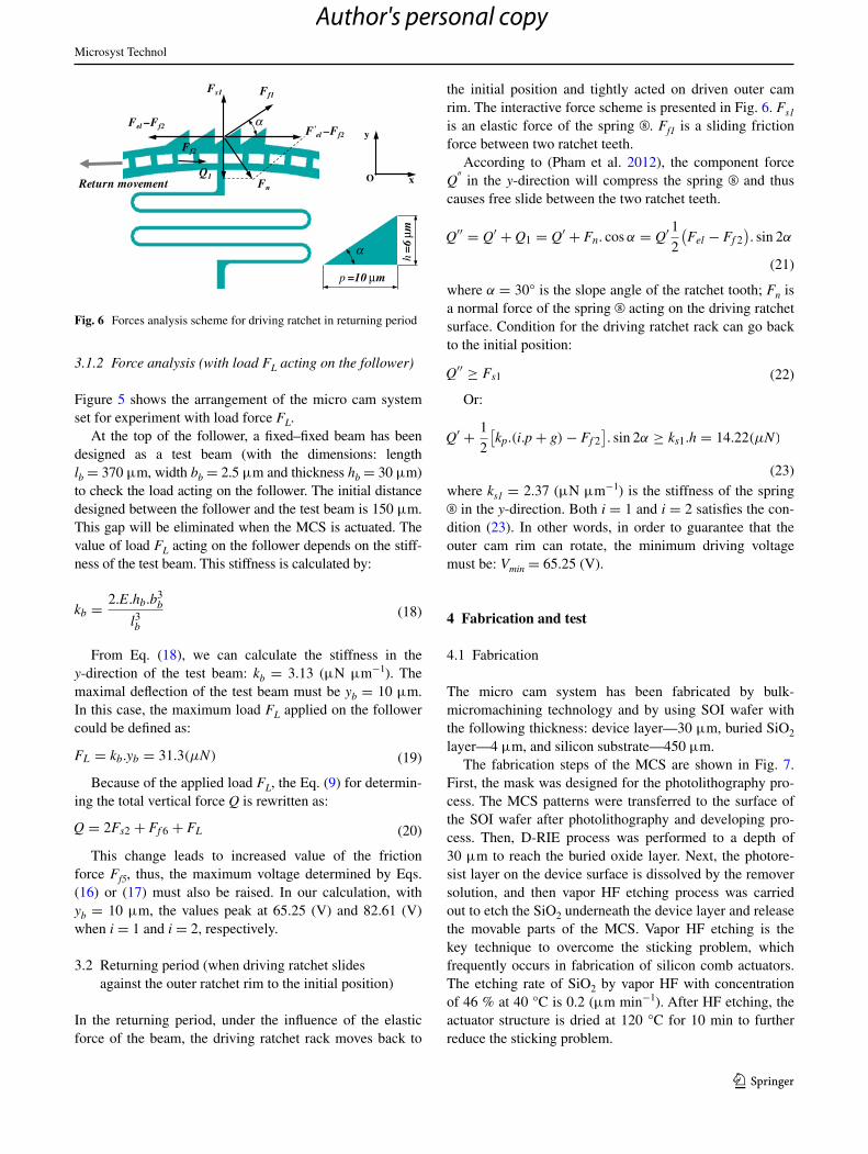
The McS tested in the loading condition (with FL > 0) is illustrated in Fig. 10. In Fig. 10a, the follower started to move toward the test beam when the periodic voltage was applied. In Fig. 10b, the follower pushed and deformed the test beam. The maximum displacement of the test beam must be 10 μm due to the designed length of the follower stroke of 160 μm. In the both cases, the McS smoothly ran at applied voltages Vpp = 80 and 100 V.
5 Characterization of MCS
In theory, the time for the cam rim to rotate one full round can be expressed by:
where z = 740 is the number of ratchet teeth of the outer cam rim, and f is the driving frequency. The integer number i = 1, 2, etc. which was mentioned in the Sect. 3.1.1, depends on the displacement of the driving ratchet rack, or in other words, on the amplitude of the driving voltage. The theoretical angular velocity ω of the cam rim can be expressed below:
To perform the operational test, four anti-reverse mech-anisms ③ were actuated and set to the locked-position by
(24)t =z
60.i.f=
740
60.i.f=
37
3.i.f(min)
(25)ω =1
t=
3.i.f
37(rpm)
Fig. 7 Fabrication process (a) Preparation step
Si layer of 30µm
SiO2 layer of 4µm
Silicon substrate
Photoresist layer(PR mask)
(b) Lithography and developing (d) Vapor HF etching process
(c) DRIE process
SiO2 layer
Silicon substrate
Fixed parts
Movable parts
Fig. 8 SeM image of the McS and its components
Fig. 9 The video-captured image of the McS
Author's personal copy
Microsyst Technol
1 3
using a probe station equipped with a microscope, and then the square wave driving voltage was applied to the elec-trodes of four electrostatic comb-drive actuators through probes. In order to successfully perform the operation, the McS was driven by a periodic voltage (Vpp = 80 V if i = 1, 100 V if i = 2) and the driving frequencies ranged from 1 to 20 hz. In our test, the follower effectively pushed the test beam, and the deflection of the beam approached the expected value of 10 μm (Fig. 10b).
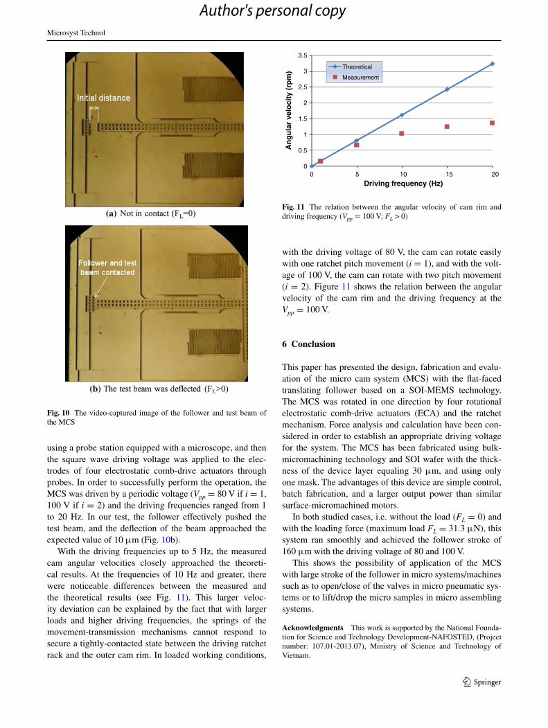
With the driving frequencies up to 5 hz, the measured cam angular velocities closely approached the theoreti-cal results. at the frequencies of 10 hz and greater, there were noticeable differences between the measured and the theoretical results (see Fig. 11). This larger veloc-ity deviation can be explained by the fact that with larger loads and higher driving frequencies, the springs of the movement-transmission mechanisms cannot respond to secure a tightly-contacted state between the driving ratchet rack and the outer cam rim. In loaded working conditions,
with the driving voltage of 80 V, the cam can rotate easily with one ratchet pitch movement (i = 1), and with the volt-age of 100 V, the cam can rotate with two pitch movement (i = 2). Figure 11 shows the relation between the angular velocity of the cam rim and the driving frequency at the Vpp = 100 V.
6 Conclusion
This paper has presented the design, fabrication and evalu-ation of the micro cam system (McS) with the flat-faced translating follower based on a SOI-MeMS technology. The McS was rotated in one direction by four rotational electrostatic comb-drive actuators (eca) and the ratchet mechanism. Force analysis and calculation have been con-sidered in order to establish an appropriate driving voltage for the system. The McS has been fabricated using bulk-micromachining technology and SOI wafer with the thick-ness of the device layer equaling 30 μm, and using only one mask. The advantages of this device are simple control, batch fabrication, and a larger output power than similar surface-micromachined motors.
In both studied cases, i.e. without the load (FL = 0) and with the loading force (maximum load FL = 31.3 μn), this system ran smoothly and achieved the follower stroke of 160 μm with the driving voltage of 80 and 100 V.
This shows the possibility of application of the McS with large stroke of the follower in micro systems/machines such as to open/close of the valves in micro pneumatic sys-tems or to lift/drop the micro samples in micro assembling systems.
Acknowledgments This work is supported by the national Founda-tion for Science and Technology Development-naFOSTeD, (Project number: 107.01-2013.07), Ministry of Science and Technology of Vietnam.
Fig. 10 The video-captured image of the follower and test beam of the McS
0
0.5
1
1.5
2
2.5
3
3.5
0 5 10 15 20
An
gu
lar
velo
city
(rp
m)
Driving frequency (Hz)
Theoretical
Measurement
Fig. 11 The relation between the angular velocity of cam rim and driving frequency (Vpp = 100 V; FL > 0)
Author's personal copy

Microsyst Technol
1 3
References
allen JJ, Schriner hK (1998) Micromachine wedge stepping motor. In: aSMe international mechanical engineering congress and expositions-MeMS symposia, anaheim
Barnes SM, Miller Sl, rodgers MS, Bitsie F (2000) Torsional ratch-eting actuating system. In: Modeling and simulation of microsys-tems 2000, San Diego
chu J, Zhang r, cheng Z (2011) a novel SU-8 electrothermal micro-gripper based on the type synthesis of the kinematic chain method and the stiffness matrix method. J Micromech Microeng 21:15
Garcia eI, Sniegowski JJ (1995) Surface micromachined microen-gine as the driver for micromechanical gears. Transducers’95, Stockholm, pp 365–68
hayashi T (1994) Micromechanisms and their characteristics. In: Pro-ceedings Ieee Workshop on MeMS ‘94, ISBn 0-7803-1833-1, pp 39–44
hwang Ih, lee YG, lee Jh (2006) a micromachined friction meter for silicon sidewalls with consideration of contact surface shape. J Micromech Microeng 16:2475–2481
Kim Sh, hwang Ih, Jo KW, Yoon eS, lee Jh (2005) high-resolution inchworm linear motor based on electrostatic twisting microac-tuators. J Micromech Microeng 15:1674–1682
Kolesar eS et al (2004) electrothermal MeMS micro-engine capable of bi-directional motion. Thin Solid Films 447–8:481–488
Mehregany M, Tai Yc (1991) Surface micromachined mechanisms and micromotors. J Micromech Microeng 1:73–85
Pham Ph, Dao DV, Dang lB, Sugiyama S (2012) Single mask, sim-ple structure micro rotational motor driven by electrostatic comb-drive actuators. J Micromech Microeng 22(1):7
Polosky Ma, Garcia eJ, allen JJ (1998) Surface micromachined counter-meshing gears discrimination device. In: annual Sympo-sium on Smart Structures and Materials, San Diego
Sacks e, Barnes SM (2001) computer-aided kinematic design of a torsional ratcheting actuator. In: Proceedings of the fourth inter-national conference on modeling and simulation of microsys-tems, hilton head
Sniegowski JJ, Garcia eI (1996) Surface-micromachined gear trains driven by an on-chip electrostatic microengine. Ieee electron Device lett 17(7):366–368
Steven rogers M (1998) Designing and operating electrostatically driven microengines. In: Proceedings of the 44th international instrumentation symposium, reno, pp 56–65
Tanner DM (2001) reliability of a MeMS torsional ratcheting actua-tor. In: Ieee 39th annual international reliability physics sympo-sium, Orlando, pp 81–90
Yeh r, hollar S, Pister KSJ (2002) Single mask, large force, and large displacement electrostatic linear inchworm motors. J Microelec-tromech Syst 11(4):330–336
Author's personal copy