Analog/RF Performance of Multichannel SOI MOSFET
10
IEEE TRANSACTIONS ON ELECTRON DEVICES, VOL. 56, NO. 7, JULY 2009 1473 Analog/RF Performance of Multichannel SOI MOSFET Tao Chuan Lim, Member, IEEE, Emilie Bernard, Olivier Rozeau, Thomas Ernst, Member, IEEE, Bernard Guillaumot, Nathalie Vulliet, Christel Buj-Dufournet, Michel Paccaud, Sylvie Lepilliet, Gilles Dambrine, Member, IEEE, and François Danneville, Member, IEEE Abstract—In this paper, for the first time, we present a detailed RF experimental and simulation study of a 3-D multichannel SOI MOSFET (MCFET). Being different from the conventional pla- nar technology, the MCFET features a total of three self-aligned TiN/HfO 2 gate stacks fabricated on top of each other, allowing current to flow through the three undoped ultrathinned silicon bodies (UTBs). In other words, the operation of the MCFET is theoretically based on two UTB double-gate SOIs and a single-gate UTB fully depleted SOI (FDSOI) at the bottom. Using on-wafer S-parameters, the RF/analog figures-of-merit of an MCFET with a gate length of 50 nm are extracted and discussed. Thanks to the enormous transconductance (g m ) and very low output conduc- tance, the RF/analog performances of MCFET-voltage gain (A VI ) and early voltage (V EA ) are superior compared with that of the single-gate UTB-FDSOI. However, these advantages diminish in terms of transition frequency (f T ), due to the large total input gate capacitances (C GG ). This inspires the introduction of spacer engineering in MCFET, aiming at improving both C GG and f T . The sensitivity of the spacer length to the RF/analog performances is experimentally analyzed, and the performance optimization is validated using ac simulation. This paper concludes that op- timized MCFETs are a serious contender to the mainstream MOSFETs including FinFETs for realizing future low-power ana- log applications. Index Terms—Early voltage, high frequency (HF), multichannel MOSFET, silicon, silicon-on-insulator (SOI), voltage gain. Manuscript received November 19, 2008; revised April 1, 2009. First pub- lished June 2, 2009; current version published June 19, 2009. The review of this paper was arranged by Editor J. Woo. T. C. Lim and S. Lepilliet are with the Équipe ANODE, Institut d’Electronique de Microélectronique et de Nanotechnologie, UMR CNRS 8520, 59652 Villeneuve d’Ascq, France (e-mail: [email protected] lille1.fr). E. Bernard, B. Guillaumot, and N. Vulliet are with the Commis- sariat à l’Energie Atomique/Laboratoire d’Electronique et Technologie de l’Information, Minatec, 38054 Grenoble, France, and also with SGS-Thomson Microelectronics, 38926 Crolles, France (e-mail: [email protected]). O. Rozeau, T. Ernst, C. Buj-Dufournet, and M. Paccaud are with the Commissariat à l’Energie Atomique/Laboratoire d’Electronique et des Technologies de l’Information, Minatec, 38054 Grenoble, France (e-mail: [email protected]). G. Dambrine is with the Micro/Nano- and Opto-electronic Department and the Équipe ANODE, Institut d’Electronique de Microélectronique et de Nanotechnologie, UMR CNRS 8520, 59652 Villeneuve d’Ascq, France, and also with the University of Lille, 59652 Villeneuve d’Ascq, France. F. Danneville is with the Équipe ANODE, Institut d’Electronique de Microélectronique et de Nanotechnologie, UMR CNRS 8520, 59652 Vil- leneuve d’Ascq, France, and also with the University of Lille, 59652 Villeneuve d’Ascq, France (e-mail: [email protected]). Color versions of one or more of the figures in this paper are available online at http://ieeexplore.ieee.org. Digital Object Identifier 10.1109/TED.2009.2021438 I. INTRODUCTION O VER the past 40 years, the growth of the semiconductor industry has been governed by the continuous perfor- mance improvement of MOSFETs via aggressive device scal- ing. It has been widely acknowledged that the scaling capability of the silicon-on-insulator (SOI)-based classical or nonclassical MOS technology is more superior to that of the conventional bulk technology. This therefore led to the introduction of sev- eral SOI structures such as the partially depleted SOI (PDSOI [1]–[3])/fully depleted SOI (FDSOI [4]–[6]), double-gate SOI (DGSOI [7], [8]), multiple-gate MOSFETs (MuGFET or FinFET [9]–[13]), etc. The FinFET, in particular, has received tremendous attention and is one of the most likely candidates to replace planar-based MOSFETs for the sub-32-nm technology node. This is because, in a FinFET design, the gate is wrapped around the silicon pillar, yielding not one but three gates (if the fin height is sufficiently short) that guarantee efficient channel control and reduced short-channel effects (SCEs) such as subthreshold slope (S), drain-induced barrier lowering, and threshold voltage roll-off (ΔV TH ). However, due to the inher- ent 3-D standing, the most critical issue to be addressed in the fabrication/manufacturing process for any ultrascaled FinFET design is the difficulty in controlling the line-edge roughness (LER) during the patterning steps [14], which will ultimately result in severe variation in several key geometrical parameters, such as the size of the top gate, the length of two side gates, as well as the thickness of thin fin width. As a consequence, the device is more prone to performance degradation. In order to preserve the idea of having more gates to efficiently control and to increase the current drive in the channel such as that achieved in FinFETs, a planarly fabri- cated innovative transistor has been recently demonstrated. It is known as the multichannel SOI MOSFET (MCFET) [15]– [20]. Due to its unique fabrication processes, the MCFET design is not only free from LER impact but also offers higher layout robustness and compactness compared with that of FinFET technology [19]. MCFETs also conduct more current than FinFETs where the self-aligned gates define a total of five channels in strong inversion: four channels composed by two ultrathinned body DGSOIs (UTB-DGSOIs) and another channel at the bottom, formed by an FDSOI (UTB-FDSOI). However, recent dc studies revealed that the series source/drain resistances (R SD ) in MCFETs are particularly high, with values reaching 900 Ω · μm, compared with only 260 Ω · μm of a typical planar FDSOI having the same gate stack of TiN/HfO 2 0018-9383/$25.00 © 2009 IEEE
Transcript of Analog/RF Performance of Multichannel SOI MOSFET

IEEE TRANSACTIONS ON ELECTRON DEVICES, VOL. 56, NO. 7, JULY 2009 1473
Analog/RF Performance of MultichannelSOI MOSFET
Tao Chuan Lim, Member, IEEE, Emilie Bernard, Olivier Rozeau, Thomas Ernst, Member, IEEE,Bernard Guillaumot, Nathalie Vulliet, Christel Buj-Dufournet, Michel Paccaud, Sylvie Lepilliet,
Gilles Dambrine, Member, IEEE, and François Danneville, Member, IEEE
Abstract—In this paper, for the first time, we present a detailedRF experimental and simulation study of a 3-D multichannel SOIMOSFET (MCFET). Being different from the conventional pla-nar technology, the MCFET features a total of three self-alignedTiN/HfO2 gate stacks fabricated on top of each other, allowingcurrent to flow through the three undoped ultrathinned siliconbodies (UTBs). In other words, the operation of the MCFET istheoretically based on two UTB double-gate SOIs and a single-gateUTB fully depleted SOI (FDSOI) at the bottom. Using on-waferS-parameters, the RF/analog figures-of-merit of an MCFET witha gate length of 50 nm are extracted and discussed. Thanks to theenormous transconductance (gm) and very low output conduc-tance, the RF/analog performances of MCFET-voltage gain (AVI)and early voltage (VEA) are superior compared with that of thesingle-gate UTB-FDSOI. However, these advantages diminish interms of transition frequency (fT ), due to the large total inputgate capacitances (CGG). This inspires the introduction of spacerengineering in MCFET, aiming at improving both CGG and fT .The sensitivity of the spacer length to the RF/analog performancesis experimentally analyzed, and the performance optimizationis validated using ac simulation. This paper concludes that op-timized MCFETs are a serious contender to the mainstreamMOSFETs including FinFETs for realizing future low-power ana-log applications.
Index Terms—Early voltage, high frequency (HF), multichannelMOSFET, silicon, silicon-on-insulator (SOI), voltage gain.
Manuscript received November 19, 2008; revised April 1, 2009. First pub-lished June 2, 2009; current version published June 19, 2009. The review of thispaper was arranged by Editor J. Woo.
T. C. Lim and S. Lepilliet are with the Équipe ANODE, Institutd’Electronique de Microélectronique et de Nanotechnologie, UMR CNRS8520, 59652 Villeneuve d’Ascq, France (e-mail: [email protected]).
E. Bernard, B. Guillaumot, and N. Vulliet are with the Commis-sariat à l’Energie Atomique/Laboratoire d’Electronique et Technologie del’Information, Minatec, 38054 Grenoble, France, and also with SGS-ThomsonMicroelectronics, 38926 Crolles, France (e-mail: [email protected]).
O. Rozeau, T. Ernst, C. Buj-Dufournet, and M. Paccaud are withthe Commissariat à l’Energie Atomique/Laboratoire d’Electronique et desTechnologies de l’Information, Minatec, 38054 Grenoble, France (e-mail:[email protected]).
G. Dambrine is with the Micro/Nano- and Opto-electronic Departmentand the Équipe ANODE, Institut d’Electronique de Microélectronique et deNanotechnologie, UMR CNRS 8520, 59652 Villeneuve d’Ascq, France, andalso with the University of Lille, 59652 Villeneuve d’Ascq, France.
F. Danneville is with the Équipe ANODE, Institut d’Electroniquede Microélectronique et de Nanotechnologie, UMR CNRS 8520, 59652 Vil-leneuve d’Ascq, France, and also with the University of Lille, 59652 Villeneuved’Ascq, France (e-mail: [email protected]).
Color versions of one or more of the figures in this paper are available onlineat http://ieeexplore.ieee.org.
Digital Object Identifier 10.1109/TED.2009.2021438
I. INTRODUCTION
OVER the past 40 years, the growth of the semiconductorindustry has been governed by the continuous perfor-
mance improvement of MOSFETs via aggressive device scal-ing. It has been widely acknowledged that the scaling capabilityof the silicon-on-insulator (SOI)-based classical or nonclassicalMOS technology is more superior to that of the conventionalbulk technology. This therefore led to the introduction of sev-eral SOI structures such as the partially depleted SOI (PDSOI[1]–[3])/fully depleted SOI (FDSOI [4]–[6]), double-gate SOI(DGSOI [7], [8]), multiple-gate MOSFETs (MuGFET orFinFET [9]–[13]), etc. The FinFET, in particular, has receivedtremendous attention and is one of the most likely candidates toreplace planar-based MOSFETs for the sub-32-nm technologynode. This is because, in a FinFET design, the gate is wrappedaround the silicon pillar, yielding not one but three gates (ifthe fin height is sufficiently short) that guarantee efficientchannel control and reduced short-channel effects (SCEs) suchas subthreshold slope (S), drain-induced barrier lowering, andthreshold voltage roll-off (ΔVTH). However, due to the inher-ent 3-D standing, the most critical issue to be addressed in thefabrication/manufacturing process for any ultrascaled FinFETdesign is the difficulty in controlling the line-edge roughness(LER) during the patterning steps [14], which will ultimatelyresult in severe variation in several key geometrical parameters,such as the size of the top gate, the length of two side gates, aswell as the thickness of thin fin width. As a consequence, thedevice is more prone to performance degradation.
In order to preserve the idea of having more gates toefficiently control and to increase the current drive in thechannel such as that achieved in FinFETs, a planarly fabri-cated innovative transistor has been recently demonstrated. Itis known as the multichannel SOI MOSFET (MCFET) [15]–[20]. Due to its unique fabrication processes, the MCFETdesign is not only free from LER impact but also offers higherlayout robustness and compactness compared with that ofFinFET technology [19]. MCFETs also conduct more currentthan FinFETs where the self-aligned gates define a total offive channels in strong inversion: four channels composed bytwo ultrathinned body DGSOIs (UTB-DGSOIs) and anotherchannel at the bottom, formed by an FDSOI (UTB-FDSOI).However, recent dc studies revealed that the series source/drainresistances (RSD) in MCFETs are particularly high, with valuesreaching 900 Ω · μm, compared with only 260 Ω · μm of atypical planar FDSOI having the same gate stack of TiN/HfO2
0018-9383/$25.00 © 2009 IEEE

1474 IEEE TRANSACTIONS ON ELECTRON DEVICES, VOL. 56, NO. 7, JULY 2009
Fig. 1. Main process steps for the MCFET. Step 1: Epitaxy of the Si/SiGe superlattice. Step 2: The gate length definition. Step 3: Source/drain epitaxy andimplantation. Step 4: Active etch and SiGe access. Step 5: Selective isotropic etching of SiGe. Step 6: Gate stack definition of TiN/HfO2. Step 7: Formation ofnitride spacers and source/drain salicidation. Final Steps: Standard BEOL.
[20]. Therefore, the degraded RF performance of MCFETs isanticipated, i.e., MCFETs will NOT experimentally yield fivetimes (due to five channels) gm compared with a single-gateUTB-FDSOI. Despite these apparent shortcomings, the scaledMCFET (∼50 nm) still offers an exciting performance byexhibiting very large ION/IOFF ratios greater than six decadesdue to excellent SCEs and very low IOFF (therefore satisfyingthe need for low-standby-power applications) while attaininghigh ION (therefore satisfying the need for high-performanceapplications) [21].
In this paper, we investigate the RF behavior of the MCFET.Detailed RF measurements and the extraction of the high-frequency (HF) properties are carried out on MCFETs withgate lengths as short as ∼50 nm. Results are compared with thesingle-gate FDSOI featuring the same gate stack of TiN/HfO2.In this paper, we also report on the impact of the source/drainengineering of MCFETs on RF performance experimentally byintroducing a spacer region between the gate and the heavilydoped source/drain region. This spacer study is further en-hanced by ac small-signal simulations to provide more insightsrelated to the influence of spacers on HF properties.
II. PROCESS DESCRIPTION
The self-aligned MCFET fabrication processes are devel-oped in the Commissariat à l’Energie Atomique/Laboratoired’Electronique et Technologie de l’Information (CEA/LETI)using a standard microelectronics clean room and masks.The complete fabrication steps are shown in Fig. 1. First, a(25-nm Si/30-nm Si0.8Ge0.2) × 3 superlattice was epitaxiallygrown on the SOI substrate using the reduced pressure chemicalvapor deposition (CVD). The superlattice was then etched witha gate mask down to the SOI layer. The crystalline siliconsource and drain (S/D) were then selectively grown and im-planted. In this step, special interest has been taken to ensurethat the S/D epitaxy is specifically grown up until the top gatestack rather than halfway through the superlattice (as demon-strated in [17]). This optimization was realized in the effortof minimizing the series resistances in the source/drain region.Next, the SiGe layers were selectively removed using pure CF4
at high pressure and low microwave power in a remote plasmatool. This is followed by the deposition of the gate stacks, whichconsists of a 3-nm atomic layer deposition of HfO2, 10-nmCVD of midgap gate titanium nitride (TiN), and 100-nm N+
polysilicon layers. The final capacitance equivalent thicknessis measured to be ∼1.95 nm in inversion. After the formationof the nitride spacers and dopant activation anneal, the S/D
Fig. 2. Cross-sectional TEM picture of MCFET and FDSOI.
TABLE IKEY PARAMETERS OF MEASURED MCFET
were silicided with NiSi and finally followed by the standardback end of line (BEOL) process. For RF measurement, thenumber of fingers, which is 25, is designed to minimize thegate resistances, and the final unit width (WU ) of the MCFETis only 0.5 μm. Hence, the effective total width for the MCFETis 12.5 μm. For comparison purposes, a single-gate undopedUTB-FDSOI was fabricated featuring a similar gate stack aswell as silicon thickness. Its process technology is described in[6]. The final cross-sectional TEM picture of the MCFET andUTB-FDSOI structures are shown in Fig. 2, where the LG isestimated to be ∼50 and ∼55 nm in MCFET and UTB-FDSOI,respectively. The key geometrical parameters for both devicesare listed in Table I.
III. CHARACTERIZATION PROCEDURES
This section reports on the extraction of the HF propertiesof the MCFET and UTB-FDSOI. On-wafer S-parameters havebeen measured, up to 45 GHz, using a Microwave Network An-alyzer [vectorial network analyzer (VNA)] (Agilent 8753ES)

LIM et al.: ANALOG/RF PERFORMANCE OF MULTICHANNEL SOI MOSFET 1475
Fig. 3. DC characteristics of MCFET (LG = 50 nm) and UTB-FDSOI (LG = 55 nm). (a) Left plot shows the IDS–VGS characteristics at VDS = 1.2 V.(b) Right plot shows the IDS–VDS characteristics at various VGS from 0–1.2 V with steps of 0.2 V.
for various gate and drain biases. The probe calibration wasperformed using an off-wafer Short-Open-Load-Thru proce-dure. Corrected Y -parameters are subsequently obtained bysubtracting those of the associated open test structure from theY -parameters of the device under test in order to de-embedcoplanar accesses. A more complex de-embedding with a shorttest structure is not required for this frequency range [6]. All theHF properties and figures-of-merit (FoMs) are then extractedand evaluated directly from these extrinsic Y -parameters. Atpresent, the small-signal parameters of the MCFET were notstudied because we believe that the extracted intrinsic parame-ters from the conventional small-signal equivalent circuit(SSEC) such as in [6] are questionable. Nevertheless, eval-uating data using only extrinsic parameters is more genuineand sufficient in providing insights regarding the HF propertiesof MCFET. The extraction procedure is summarized in theAppendix.
IV. EXPERIMENTAL RESULTS AND DISCUSSIONS
A. DC Characteristics
Fig. 3 shows the dc characteristics for the MCFET andUTB-FDSOI. From the IDS–VGS plot, it is observed that thethreshold voltage (VTH) at maximum VDS = 1.2 V is higherin UTB-FDSOI than in MCFET. These VTH differences canbe due to, for example, the following: 1) the overestimation ofthe effective LG for MCFET and 2) the fact that LG for thereferenced UTB-FDSOI is longer (∼55 nm). In this paper, theVTH differences will not severely affect the outcome of the RFstudy. From these plots, the SCEs in both devices are minimalas the subthreshold slopes are less than 100 mV/decade. IOFF,albeit higher for the MCFET (due to lower VTH) by almost twodecades, it is still very low, and as a result, high ION/IOFF
ratios > 6 are attained. The distinction between the MCFETand UTB-FDSOI is more clearly observed at maximum gatevoltage. Despite the higher series resistances (nearly threefoldcompared with UTB-FDSOI) [20], the MCFET is still ableto produce an ION of > 103 mA/mm, whereas the ION ofonly ∼400 mA/mm is achieved in UTB-FDSOI, resulting in
a current ratio that is three times higher in MCFET than inUTB-FDSOI.
B. RF Characteristics
The extrinsic HF properties of transconductance (gm), outputconductance (gDS), and total input capacitances (CGG) arededuced from the real and imaginary parts of the Y -matrix asfollows:
gm =�e{Y21} (1)
gDS =�e{Y22} (2)
CGG =�m{Y11 + Y12}
ω(3)
where ω = 2πf . Unless specified, the parameters are extractedat an operating frequency of 8 GHz. The impact of the VTH
difference is removed by plotting all key FoMs as a func-tion of IDS. Fig. 4 shows the comparison between the gm
(a) and gDS (b) for both MCFET and UTB-FDSOI. For thereferenced UTB-FDSOI, the maximum gm obtained is only∼750 mS/mm, a value lower than that normally achievedin conventional bulk designs (∼1000 mS/mm) for the sametechnology node. This gm degradation is attributed to thesurface scattering or some undesirable traps at the interfacebetween the high-κ dielectric and the thin silicon [6]. Never-theless, the gm in MCFET, as shown in Fig. 4(a), is greaterthan 1800 mS/mm at VGS = VDS = 1.2 V. This can be re-garded as the highest gm ever recorded for any silicon-basedtechnology at room temperature and is expected to reach2000 mS/mm with a slight optimization of series resistances.It must be noted that this gm value measured includes an RSD
of ∼900 Ω · μm (i.e., the intrinsic gm will be very large).At IDS ∼ 400 mA/mm (maximum current for UTB-FDSOI),MCFET easily outperformed UTB-FDSOI by two to one. An-other interesting parameter that significantly benefits MCFETis the very low value of the gDS. The extracted gDS, as shownin Fig. 4(b), starts to increase with IDS, with the increasebeing dominating for UTB-FDSOI as compared with that ofMCFET. Taking 10 mA/mm (∼ IDS near VTH) as an example,

1476 IEEE TRANSACTIONS ON ELECTRON DEVICES, VOL. 56, NO. 7, JULY 2009
Fig. 4. Extraction of (a) gm and (b) gDS for MCFET and UTB-FDSOI. The operation frequency is at 8 GHz. VDS = 1.2 V.
Fig. 5. Extraction of (a) AVI (= gm/gDS) in decibels, (b) VEA (= IDS/gDS), and (c) gm/IDS ratio for MCFET and UTB-FDSOI. The operation frequencyis at 8 GHz. VDS = 1.2 V.
gDS ∼ 16 mS/mm is extracted for UTB-FDSOI compared withonly half of that (∼8 mS/mm) for MCFET. This trend con-tinues in the strong inversion region where, at 400 mA/mm,the gDS in MCFET is still two times lower than that of the UTB-FDSOI MOSFET.
The resultant of a twice higher gm and twice lower gDS inMCFET can be directly translated into an improvement in volt-age gain (AVI = gm/gDS) by fourfold (in linear). This is shownin Fig. 5(a) where the MCFET’s AVI is > 10 dB larger than thatof the UTB-FDSOI. This result is very encouraging for a scaledLG ∼ 50 nm in silicon technology; AVI values are generallyaround ∼20 dB (similar to our referenced UTB-FDSOI [6] inFig. 5(a), PDSOI at Lpoly = 46 nm [3]) or below for FinFETsat only ∼15 dB as experimentally observed in [13]. Therefore,in analog design, a 50-nm MCFET offers an attractive AVI
of > 30 dB, thus competing with devices designed for longerLG (> 100 nm). Thanks to the lower gDS, MCFET is alsoa better candidate for realizing future low-power low-voltage(LV) analog applications as, at IDS ∼ 10 mA/mm, the AVI ofMCFET already crosses beyond 25 dB as opposed to that ofUTB-FDSOI at ∼20 dB.
Other crucial FoMs for analog applications are the earlyvoltage (VEA = IDS/gDS) and the transconductance-to-current
ratio (gm/IDS). As shown in Fig. 5(b), for IDS values> 10 mA/mm, MCFET outperforms UTB-FDSOI in VEA bytwo to one due to the lower gDS. In fact, again, for such scaleddevice, MCFET recorded a very high VEA in the moderateand strong inversion regions, i.e., nearly 2 V at 10 mA/mmfor LV applications, 10 V for 400 mA/mm (maximum currentfor the referenced UTB-FDSOI at VDS = VGS = 1.2 V), and16 V at 103 mA/mm (maximum current for MCFET at VDS =VGS = 1.2 V). gm/IDS, on the other hand, is a universal/non-dimension-dependent metric that measures the efficiency totranslate current (hence, power) into transconductance. In thiscase, we analyze this metric behavior in two inversion regions,i.e., weak inversion region (WI) and moderate/strong inversionregion (M/SI). In WI, the gm/IDS values for both devicesconverge at a value of ∼22 V−1. Using the basic formula ofS (= ln(10)/(gm/IDS)), it is validated that both devices do notexhibit severe SCEs as S is calculated to be < 100 mV/decade.It is recognized that these values are slightly larger than thatobserved using IDS–VGS characteristics [Fig. 3(a)]. In the M/SI,thanks to the large gm, the gm/IDS ratio of the MCFET isconsistently ∼3 V−1 higher than the UTB-FDSOI throughoutthe region, demonstrating a better efficiency of MCFET inachieving gain (like an amplifier) for any given IDS.

LIM et al.: ANALOG/RF PERFORMANCE OF MULTICHANNEL SOI MOSFET 1477
Fig. 6. Extracted (a) CGG, (b) H21 gain, and fT (= gm/2πCGG) for MCFET and UTB-FDSOI. The operation frequency for (a) and (c) is at 8 GHz, andVDS = 1.2 V. For (b), VGS = VDS = 1.2 V
Despite having a high gm and low gDS, MCFET severelysuffers from the high value of parasitic capacitances. In thispaper, using (3), we analyze the trend of the total input capaci-tances (CGG) of MCFET with a variation of IDS and comparewith that of UTB-FDSOI, where CGG = CGS + CGD, CGS isthe gate to source capacitance, and CGD is the gate to draincapacitance. For the operation of the transistor, we can alsodefine CGG in the first order as CIN + Cfrin, where CIN is theintrinsic gate-channel capacitance associated with the action ofthe gate in the creation of the conducting channel and Cfrin
is the total fringing capacitance (associated internally due tothe overlap doping under the gate and/or associated externallyresulting from the gate electrode to the S/D contact). The Cfrin
can simply be identified by limiting CGG at zero or negativeVGS [corresponding to the lowest IDS shown in Fig. 6(a)]. It isapparent that the Cfrin for MCFET is approximately five timesmore than that of UTB-FDSOI, demonstrating the negativeimplication in having five gates (three gate stacks) in MCFET.When VGS is increased to a maximum of 1.2 V, the active capac-itive component in the silicon CIN starts to modulate; surpris-ingly, the ratio achieved for CIN for MCFET to UTB-FDSOIis also approximately five, where CIN_MCFET ∼ 2500 fF/mmwhile CIN_FDSOI ∼ 500 fF/mm. This is theoretically possi-ble if one assumes that the behavior of the five conductingchannels are the same, i.e., similar thicknesses for each of theinversion layer and same number of charge per unit area (Qs)induced in each inversion layer formed in the SI regime of theDGSOIs and UTB-FDSOI at the bottom. Unfortunately, it isacknowledged that such ideal case in MCFET is difficult toprove as it requires the “dissection” of MCFET and thoroughanalyses of the contribution of each capacitance component foreach gate. Nevertheless, as the IDS increases, the total ratioof CGG measured for MCFET/UTB-FDSOI shrinks slightly,from approximately five at 10 mA/mm to approximately fourat 400 mA/mm. No doubt, CGG will be the key parameter thatattributes to the degradation of the transition frequency (fT ).
Fig. 6(b) shows the gain (H21) variation with frequenciesfor both devices at maximum VGS = VDS = 1.2 V. fT is thenextracted from the −20-dB extrapolation of this plot and can berelated to gm and CGG by fT = gm/(2πCGG). At a single fre-quency of 8 GHz, fT is plotted as a function of IDS in Fig. 6(c).
MCFET, in this case, is undesirable for LV applications (IDS =10 mA/mm) as the fT for MCFET is approximately fourtimes lower than that of UTB-FDSOI. This is because, in thisoperation regime, MCFET not only suffers from a large CGG
[Fig. 6(a)] but also fT_MCFET does not benefit from the tinyincrement of gm [Fig. 4(a)]. This ratio, however, improves at theSI region, thanks to the massive rate of increment of gm withIDS [Fig. 4(a)] successfully compensating parts of the largeCGG [Fig. 6(a)].
In conclusion, MCFET endures a similar deficiency toFinFET: high total input capacitances CGG. Even the large gm
in MCFET cannot compensate the large CGG, hence resultingin degradation in any FoMs related to CGG including fT ,maximum oscillation frequency (fMAX), and minimum noisefigure (NFMIN). In the effort to reduce CGG, we explore theconcept of S/D spacer engineering in MCFET and study theimpact of the spacer to all key RF FoMs in the next section.
V. OPTIMIZATION OF MCFET VIA SPACER ENGINEERING
The concept of spacer engineering has been widely applied toimprove either the digital [22]–[24] or RF performances [25]–[27] of scaled undoped channel MOSFETs. A spacer regionis basically a buffer zone that separates the gate edge and theheavily doped S/D region. Therefore, even a subtle spacer (fora fixed doping profile under the spacer/gate) will significantlymodify the effective gate length (LEFF) in scaled devices,allowing designers to reduce IOFF while maintaining a highION. For RF/analog applications, a longer spacer (hence, longerLEFF) is highly recommended such as in DGSOI or in FinFETas this will greatly improve the gDS and minimize the Cfrin ofthe devices. Therefore, an improvement in fT is possible (aslong as there is no severe gm degradation). In this section, thisspacer concept is applied in the MCFET design in the effort tooptimize the RF performance of MCFET by reducing the CGG.
A. Spacer Fabrication
Only four steps are added to the former process fabricationscheme [20]. The process steps are shown in Fig. 7. They are

1478 IEEE TRANSACTIONS ON ELECTRON DEVICES, VOL. 56, NO. 7, JULY 2009
Fig. 7. Introduction of the spacers in the main process flow (Fig. 1). Af-ter Step 2 of the main process flow, the four steps shown in this figurewere implemented, followed by step 3 and so on in the main process flow.Step 2.1: Slight SiGe recess to create the spacers. Step 2.2: HTO deposition.Step 2.3: Deposition of nitride as material for spacer. Step 2.4: Spacer etchingto create and define the final spacer length.
Fig. 8. Cross-sectional TEM picture of MCFET with spacers.
introduced after the Si/SiGe superlattice epitaxy (step 1) andanisotropic etching (step 2) in Fig. 1.
First and foremost (step 2.1 in Fig. 7), the SiGe layersare partially etched. This step is crucial as the depth of therecess will determine the spacer length. This etching processrequires a specific in situ inductively coupled plasma processto obtain better uniformity and reproducible spacer thickness.A detailed discussion is provided in [20], comparing differenttechniques to optimize the spacer. In steps 2.2 and 2.3, oxide(HTO) and nitride layers (Si3N4) are deposited in the cavitieswith a thickness ratio optimized for the following spacer etch.The dielectrics are finally anisotropically and subsequentlyisotropically etched (step 2.4), creating an access for the silicon(channel) to the later S/D epitaxy. A careful cleaning procedureis commenced before returning to the main process flow inorder to remove entirely the dielectrics on the side to enablea correct S/D epitaxy growth (step 3 in Fig. 1). As shownin Fig. 8, the homogenous spacer thicknesses and S/D arecreated in MCFET. In this experiment, the final spacer length
Fig. 9. ATLAS simulation structure of an MCFET with spacers (not properlyscaled).
(LSPACER) which is measured from the end of HfO2 to theheavily S/D region is observed to be ∼9 nm.
B. Simulation Background
The ideal MCFET structure, as shown in Fig. 9, has beensimulated using the ATLAS 2-D simulator [28] with the nomi-nal parameters listed in Table I. For the spacer definition (insetof Fig. 9), we try to model the experimental MCFET as accu-rately as possible by setting the length of HTO (LHTO) = 3 nmand HTO thickness (tHTO) = 3 nm. The thin HfO2 is simulatedto have a permittivity (εHfO2) of ∼20. LSPACER (made ofSi3N4) is considered as the variable parameter, from as shortas 1–20 nm having a permittivity of εSi3N4 = 7.5. All simula-tions are performed using the conventional Lombardi’s mobilitymodel from ATLAS without any parameter modification. Auniform S/D doping of NSD = 1 × 20 cm−3 is assumed for theS/D region with a small doping gradient (d = 3 nm/decade)under the undoped spacer/channel region evaluated at gate edge[25]–[27].
C. Experimental/Simulation Results
The simulated and experimental dc IDS–VGS and ac gm−IDS
characteristics are shown in Fig. 10. It should be stronglystressed here that the purpose of MCFET simulation is onlyto qualitatively reaffirm the results experimentally obtainedwith regard to spacer engineering, and the following resultsshould not be quantitatively analyzed. Therefore, a large offsetbetween simulation and experimental results, for example, nearthe IOFF and ION current region [Fig. 10(a)] and gm partic-ularly at maximum IDS [Fig. 10(b)] region, is expected. Thesimulated and experimental results at VGS = VDS = 1.2 V aresummarized in Table II.
First of all, one of the results of increasing LSPACER is thedecrement of gm. This effect is noted experimentally as shownin Table II and Fig. 11(a), where gm degrades by almost 15%,from 1861 down to 1568 mS/mm. This, in theory, is mainlyattributed to the increase of series resistances associated to theunderlap regions which resulted in a longer LEFF [22]–[27].

LIM et al.: ANALOG/RF PERFORMANCE OF MULTICHANNEL SOI MOSFET 1479
Fig. 10. DC characteristics of experimental and simulated MCFET with spacers of 9 nm (LG = 50 nm). (a) Left plot shows the IDS–VGS characteristics atVDS = 1.2 V. (b) Right plot shows the gm−IDS characteristics. All at VDS = 0.2 V. Lines are the simulation results. Symbols are the experimental results.
TABLE IIANALOG PERFORMANCE OF MEASURED/SIMULATED MCFET
Fig. 11. Variation of (a) gm, (b) CGG, and (c) fT with spacer lengthLSPACER. VGS = VDS = 1.2 V. The operation frequency is at 8 GHz. Linesare the simulation results for MCFET with spacers, varying from 1 to 20 nm.Triangles are the experimental results. Circles are the simulated data forMCFET without spacers. Note that no HTO is deposited in the experiment andsimulation for “MCFET without spacer.”
As widely reported, one of the major advantages of definingspacers at each side of the gate is the ability to reduce theCGG. In this experiment, CGG is reduced by > 30% for 9-nmspacers [Fig. 11(b)]. This therefore compensates the smallergm, improving fT (= gm/2πCGG) by ∼10 GHz [Fig. 11(c)].
Using ATLAS, we analyzed the impact of spacers by increas-ing LSPACER to 20 nm. Despite the difficulty in recovering theexperimental gm for devices without spacers, it is still evidentthat the prediction of degradation in gm for a longer LSPACER
still holds true [Fig. 11(a)]. Similarly, simulation also predictedthat CGG reduced exponentially with LSPACER. In other words,at a certain length of LSPACER, both of these parameterswill compensate each other until an optimum fT is reached[Fig. 11(b) and (c)]. It is interesting to note that, from thesimulation, the optimum range of fT occurs for MCFET whenLSPACER is around 10–20 nm, i.e., LSPACER ∼ 0.2−0.4LG.For LSPACER < 10 nm, a high CGG dominates fT , while forLSPACER > 20 nm, higher series resistances under the under-lap region degrade gm and, hence, fT .
In the first order, it is possible to explain the CGG reduc-tion for MCFET with spacers using parallel plate capacitancetheory. It is reminded again that the introduction of spacersin MCFET requires the deposition of HTO and Si3N4 beforeS/D epitaxy and heavy implantation. Both of these materialshave smaller permittivity values (3.9 and 7.5 for HTO andSi3N4, respectively) than the HfO2 (∼20); thus, the total platecapacitance (in series) for each side of the gate for the MCFETwith spacers (as shown in the inset of Fig. 9) can be massivelyreduced compared with that of the MCFET without spacers.This is shown in Fig. 11(b) where the definition of a very thinHTO (∼3 nm) and Si3N4 (or LSPACER = 1 nm) could resultin the improvement of a total CGG by almost 1000 fF/mm. An-other 1000-fF/mm reduction is possible by extending LSPACER
to 20 nm.
VI. CONCLUSION
For the first time, we report the experimental RF performanceof the MCFET featuring a TiN/HfO2 gate stack of LG ∼50 nm. Compared with the UTB-FDSOI with similar gate stack,despite the large series resistances, MCFET shows enormouspotential for analog/RF applications for the following reasons.
1) The gm in MCFET is two times larger than that of UTB-FDSOI and > 1800 mS/mm at maximum current whenVGS = VDS = 1.2 V.
1480 IEEE TRANSACTIONS ON ELECTRON DEVICES, VOL. 56, NO. 7, JULY 2009
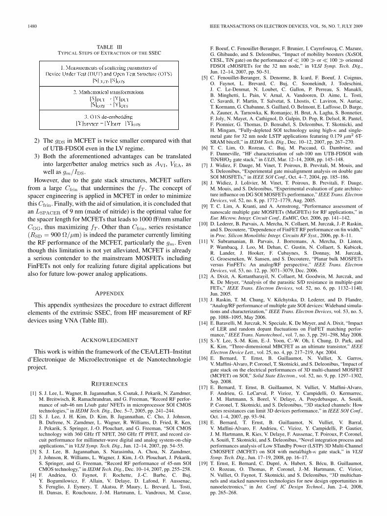
TABLE IIITYPICAL STEPS OF EXTRACTION OF THE SSEC
2) The gDS in MCFET is twice smaller compared with thatof UTB-FDSOI even in the LV regime.
3) Both the aforementioned advantages can be translatedinto larger/better analog metrics such as AVI, VEA, aswell as gm/IDS.
However, due to the gate stack structures, MCFET suffersfrom a large Cfrin that undermines the fT . The concept ofspacer engineering is applied in MCFET in order to minimizethis Cfrin. Finally, with the aid of simulation, it is concluded thatan LSPACER of 9 nm (made of nitride) is the optimal value forthe spacer length for MCFETs that leads to 1000 fF/mm smallerCGG, thus maximizing fT . Other than Cfrin, series resistance(RSD = 900 Ω/μm) is indeed the parameter currently limitingthe RF performance of the MCFET, particularly the gm. Eventhough this limitation is not yet alleviated, MCFET is alreadya serious contender to the mainstream MOSFETs includingFinFETs not only for realizing future digital applications butalso for future low-power analog applications.
APPENDIX
This appendix synthesizes the procedure to extract differentelements of the extrinsic SSEC, from HF measurement of RFdevices using VNA (Table III).
ACKNOWLEDGMENT
This work is within the framework of the CEA/LETI–Institutd’Electronique de Microélectronique et de Nanotechnologieproject.
REFERENCES
[1] S. J. Lee, L. Wagner, B. Jagannathan, S. Csutak, J. Pekarik, N. Zamdmer,M. Breitwisch, R. Ramachrandran, and G. Freeman, “Record RF perfor-mance of sub-46 nm L/sub gate/ NFETs in microprocessor SOI CMOStechnologies,” in IEDM Tech. Dig., Dec. 5–7, 2005, pp. 241–244.
[2] S. J. Lee, J. H. Kim, D. Kim, B. Jagannathan, C. Cho, J. Johnson,B. Dufrene, N. Zamdmer, L. Wagner, R. Williams, D. Fried, R. Ken,J. Pekarik, S. Springer, J.-O. Plouchart, and G. Freeman, “SOI CMOStechnology with 360 GHz fT NFET, 260 GHz fT PFET, and record cir-cuit performance for millimeter-wave digital and analog system-on-chipapplications,” in VLSI Symp. Tech. Dig., Jun. 12–14, 2007, pp. 54–55.
[3] S. J. Lee, B. Jagannathan, S. Narasimha, A. Chou, N. Zamdmer,J. Johnson, R. Williams, L. Wagner, J. Kim, J.-O. Plouchart, J. Pekarik,S. Springer, and G. Freeman, “Record RF performance of 45-nm SOICMOS technology,” in IEDM Tech. Dig., Dec. 10–14, 2007, pp. 255–258.
[4] F. Andrieu, O. Faynot, F. Rochette, J.-C. Barbe, C. Buj,Y. Bogumilowicz, F. Allain, V. Delaye, D. Lafond, F. Aussenac,S. Feruglio, J. Eymery, T. Akatsu, P. Maury, L. Brevard, L. Tosti,H. Dansas, E. Rouchouze, J.-M. Hartmann, L. Vandroux, M. Casse,
F. Boeuf, C. Fenouillet-Beranger, F. Brunier, I. Cayrefourcq, C. Mazure,G. Ghibaudo, and S. Deleonibus, “Impact of mobility boosters (XsSOI,CESL, TiN gate) on the performance of � 100 � or � 100 � orientedFDSOI cMOSFETs for the 32 nm node,” in VLSI Symp. Tech. Dig.,Jun. 12–14, 2007, pp. 50–51.
[5] C. Fenouillet-Beranger, S. Denorme, B. Icard, F. Boeuf, J. Coignus,O. Faynot, L. Brevard, C. Buj, C. Soonekindt, J. Todeschini,J. C. Le-Denmat, N. Loubet, C. Gallon, P. Perreau, S. Manakli,B. Minghetti, L. Pain, V. Arnal, A. Vandooren, D. Aime, L. Tosti,C. Savardi, F. Martin, T. Salvetat, S. Lhostis, C. Laviron, N. Auriac,T. Kormann, G. Chabanne, S. Gaillard, O. Belmont, E. Laffosse, D. Barge,A. Zauner, A. Tarnowka, K. Romanjec, H. Brut, A. Lagha, S. Bonnetier,F. Joly, N. Mayet, A. Cathignol, D. Galpin, D. Pop, R. Delsol, R. Pantel,F. Pionnier, G. Thomas, D. Bensahel, S. Deleombus, T. Skotnicki, andH. Mingam, “Fully-depleted SOI technology using high-κ and single-metal gate for 32 nm node LSTP applications featuring 0.179 μm2 6T-SRAM bitcell,” in IEDM Tech. Dig., Dec. 10–12, 2007, pp. 267–270.
[6] T. C. Lim, O. Rozeau, C. Buj, M. Paccaud, G. Dambrine, andF. Danneville, “HF characterisation of sub-100 nm UTB-FDSOI withTiN/HfO2 gate stack,” in ULIS, Mar. 12–14, 2008, pp. 145–148.
[7] J. Widiez, F. Dauge, M. Vinet, T. Poiroux, B. Previtali, M. Mouis, andS. Deleonibus, “Experimental gate misalignment analysis on double gateSOI MOSFETs,” in IEEE SOI Conf., Oct. 4–7, 2004, pp. 185–186.
[8] J. Widiez, J. Lolivier, M. Vinet, T. Poiroux, B. Previtali, F. Dauge,M. Mouis, and S. Deleonibus, “Experimental evaluation of gate architec-ture influence on DG SOI MOSFETs performance,” IEEE Trans. ElectronDevices, vol. 52, no. 8, pp. 1772–1779, Aug. 2005.
[9] T. C. Lim, A. Kranti, and A. Armstrong, “Performance assessment ofnanoscale multiple gate MOSFETs (MuGFETs) for RF applications,” inEur. Microw. Integr. Circuit Conf., EuMIC, Oct. 2006, pp. 141–142.
[10] D. Lederer, B. Parvais, A. Mercha, N. Collaert, M. Jurczak, J.-P. Raskin,and S. Decoutere, “Dependence of FinFET RF performance on fin width,”in Proc. Silicon Monolithic Integr. Circuits RF Syst., 2006, pp. 8–11.
[11] V. Subramanian, B. Parvais, J. Borremans, A. Mercha, D. Linten,P. Wambacq, J. Loo, M. Dehan, C. Gustin, N. Collaert, S. Kubicek,R. Lander, J. Hooker, F. Cubaynes, S. Donnay, M. Jurczak,G. Groeseneken, W. Sansen, and S. Decoutere, “Planar bulk MOSFETsversus FinFETs: An analog/RF perspective,” IEEE Trans. ElectronDevices, vol. 53, no. 12, pp. 3071–3079, Dec. 2006.
[12] A. Dixit, A. Kottantharayil, N. Collaert, M. Goodwin, M. Jurczak, andK. De Meyer, “Analysis of the parasitic S/D resistance in multiple-gateFETs,” IEEE Trans. Electron Devices, vol. 52, no. 6, pp. 1132–1140,Jun. 2005.
[13] J. Raskin, T. M. Chung, V. Kilchytska, D. Lederer, and D. Flandre,“Analog/RF performance of multiple gate SOI devices: Wideband simula-tions and characterization,” IEEE Trans. Electron Devices, vol. 53, no. 5,pp. 1088–1095, May 2006.
[14] E. Baravelli, M. Jurczak, N. Speciale, K. De Meyer, and A. Dixit, “Impactof LER and random dopant fluctuations on FinFET matching perfor-mance,” IEEE Trans. Nanotechnol., vol. 7, no. 3, pp. 291–298, May 2008.
[15] S.-Y. Lee, S.-M. Kim, E.-J. Yoon, C.-W. Oh, I. Chung, D. Park, andK. Kim, “Three-dimensional MBCFET as an ultimate transistor,” IEEEElectron Device Lett., vol. 25, no. 4, pp. 217–219, Apr. 2004.
[16] E. Bernard, T. Ernst, B. Guillaumot, N. Vulliet, X. Garros,V. Maffini-Alvaro, P. Coronel, T. Skotnicki, and S. Deleonibus, “Impact ofgate stack on the electrical performances of 3D multi-channel MOSFET(MCFET) on SOI,” Solid State Electron., vol. 52, no. 9, pp. 1297–1302,Sep. 2008.
[17] E. Bernard, T. Ernst, B. Guillaumot, N. Vulliet, V. Maffini-Alvaro,F. Andrieu, G. LeCarval, P. Vizioz, Y. Campidelli, O. Kermarrec,J. M. Hartmann, S. Borel, V. Delaye, A. Pouydebasque, A. Souifi,P. Coronel, T. Skotnicki, and S. Deleonibus, “3D stacked channels: Howseries resistances can limit 3D devices performance,” in IEEE SOI Conf.,Oct. 1–4, 2007, pp. 93–94.
[18] E. Bernard, T. Ernst, B. Guillaumot, N. Vulliet, V. Barral,V. Maffini-Alvaro, F. Andrieu, C. Vizioz, Y. Campidelli, P. Gautier,J. M. Hartmann, R. Kies, V. Delaye, F. Aussenac, T. Poiroux, P. Coronel,A. Souifi, T. Skotnicki, and S. Deleonibus, “Novel integration process andperformances analysis of Low STandby Power (LSTP) 3D Multi-ChannelCMOSFET (MCFET) on SOI with metal/high-κ gate stack,” in VLSISymp. Tech. Dig., Jun. 17–19, 2008, pp. 16–17.
[19] T. Ernst, E. Bernard, C. Dupré, A. Hubert, S. Bécu, B. Guillaumot,O. Rozeau, O. Thomas, P. Coronel, J.-M. Hartmann, C. Vizioz,N. Vulliet, O. Faynot, T. Skotnicki, and S. Deleonibus, “3D multichan-nels and stacked nanowires technologies for new design opportunities innanoelectronics,” in Int. Conf. IC Design Technol., Jun. 2–4, 2008,pp. 265–268.

LIM et al.: ANALOG/RF PERFORMANCE OF MULTICHANNEL SOI MOSFET 1481
[20] E. Bernard, T. Ernst, B. Guillaumot, N. Vulliet, T. C. Lim, O. Rozeau,F. Danneville, P. Coronel, T. Skotnicki, S. Deleonibus, and O. Faynot,“First internal spacers introduction in record high ION/IOFF TiN/HfO2
gate multi-channel MOSFET satisfying both high performance and lowstandby power requirements,” IEEE Electron Device Lett., vol. 30, no. 2,pp. 148–151, Feb. 2009.
[21] International Technology Roadmap for Semiconductors. [Online].Available: http://www.itrs.net/links/2005ITRS/Home2005.htm
[22] V. P. Trivedi and J. G. Fossum, “Source/drain-doping considerationsfor nanoscale FinFET design,” in IEEE SOI Conf., Oct. 4–7, 2004,pp. 192–194.
[23] T. C. Lim and G. A. Armstrong, “Parameter sensitivity for optimal designof 65 nm node double gate SOI transistors,” Solid State Electron., vol. 49,no. 6, pp. 1034–1043, Jun. 2005.
[24] Rashmi, A. Kranti, and G. A. Armstrong, “6-T SRAM cell design withnanoscale double-gate SOI MOSFETs: Impact of source/drain engineer-ing and circuit topology,” Semicond. Sci. Technol., vol. 23, no. 7, pp. 1–13,Jul. 2008.
[25] A. Kranti and G. A. Armstrong, “Source/drain extension region engi-neering in FinFETs for low-voltage analog applications,” IEEE ElectronDevice Lett., vol. 28, no. 2, pp. 139–141, Feb. 2007.
[26] T. C. Lim and G. A. Armstrong, “The impact of the intrinsic and extrinsicresistances of double gate SOI on RF performance,” Solid State Electron.,vol. 50, no. 5, pp. 774–783, May 2006.
[27] A. Kranti and G. A. Armstrong, “Design and optimization of FinFETsfor ultra-low-voltage analog applications,” IEEE Trans. Electron Devices,vol. 54, no. 12, pp. 3308–3316, Dec. 2007.
[28] ATLAS User’s Manual, SILVACO Int., Santa Clara, CA, Dec. 2005.ver. 5.10.2.R.
Tao Chuan Lim (M’07) was born in KualaTerengganu, Malaysia, on November 3, 1981. Hereceived the B.Eng. and Ph.D. degrees in micro-electronics from Queen’s University Belfast, Belfast,U.K., in 2003 and 2006, respectively. His Ph.D.degree research in the Northern Ireland Semiconduc-tor Research Centre was on the circuit and devicesimulation/modeling of the nanoscaled double-gatesilicon-on-insulator transistors.
Since November 2006, he has been with theÉquipe ANODE, Institut d’Electronique de Micro-
électronique et de Nanotechnologie, UMR CNRS 8520, Villeneuve d’Ascq,France. His current research interests include high-frequency and noise mod-eling, simulation, and characterization of advanced silicon-based devices.
Emilie Bernard was born in Oullins, France, in1982. She received the M.Sc. degree from the“Ecole Polytechnique Universitaire de Marseille,”Marseille, France, in 2005 and the Ph.D. degree fromthe “Institut National des Sciences Appliquées” deLyon, Lyon, France, in 2009.
From 2005 to 2009, she worked on the realiza-tion, characterization, simulation, and analysis ofmultichannel MOSFET devices with SGS-ThomsonMicroelectronics, Crolles, France, and with theCommissariat à l’Energie Atomique/Laboratoire
d’Electronique et Technologie de l’Information, Minatec, Grenoble, France,where she is currently working on the finalization of the design rules for 65-and 45-nm nodes.
Dr. Bernard is the recipient of the Best Young Scientist Award at the 2007European Solid State Device Research Conference in Munich.
Olivier Rozeau, photograph and biography not available at the time ofpublication.
Thomas Ernst (S’99–A’00–M’03) received theM.Sc. and Ph.D. degrees from the National Polytech-nics Institute of Grenoble, Grenoble, France, in 1997and 2000, respectively.
From 1997 to 2000, he worked on advancedsilicon-on-insulator (SOI) low-voltage and low-power CMOS electrical characterization, simulation,and modeling with L’institut de Microélectron-ique, Électromagnétisme et Photonique Laboratoryand with SGS-Thomson Microelectronics, Crolles,France. He then joined the Commissariat à l’Energie
Atomique/Laboratoire d’Electronique et des Technologies de l’Information,Minatec, Grenoble, to develop novel strained-channel CMOS architectures for32-nm technology, where, particularly, he was leading strained SOI and SiGeOICMOS integration. Since 2005, he has been in charge of 3-D stacked-channelCMOS device developments. His expertise is in the area of novel CMOSdevice fabrication technology and short-channel device analytical modeling andelectrical characterization. He is an author or coauthor of over 75 technicaljournal papers and communications at international conferences on CMOSdevice integration, modeling, and characterization.
Dr. Ernst has been a European Solid State Device Research Conferencecommittee member since 2005.
Bernard Guillaumot received the degree in hyperand radio frequency in microelectronics.
He was with the Commissariat à l’EnergieAtomique/Laboratoire d’Electronique et des Tech-nologies de l’Information (CEA/LETI), Minatec,Grenoble, France, since 1970, where he workedon magnetic memories and MNOS nonvolatile de-vices on silicon-on-sapphire. He is also currentlyheading a metal gate and multichannel advancedMOSFET program with SGS-Thomson Micro-electronics (STMicroelectronics), Crolles. He was
involved in the development of EEPROM embedded memories in microcon-trollers until 1986. After that, he was working on the EPROM 1–16-Mb devel-opment program with Thomson Semiconductors, Grenoble. In 1991, he headeda program to develop advanced Flash memories with STMicroelectronics andCEA/LETI, with special concerns for active dielectrics characterization andFlash cell reliability.
Nathalie Vulliet received the M.Sc. degree from the National PolytechnicsInstitute of Grenoble, Grenoble, France, in 1996.
She joined Thomson Semiconductors, Grenoble, in 1989. For four years, sheworked on the electrical characterization of CMOS and BiCMOS process de-velopment. In 1996, she was involved in the reliability of advanced CMOS tech-nologies with SGS-Thomson Microelectronics (STMicroelectronics), Crolles,France. In 2002, she joined the Advanced Devices team, where she wasinvolved in the common developments between STMicroelectronics and theCommissariat à l’Energie Atomique/Laboratoire d’Electronique et Technolo-gies de l’Information, Minatec, Grenoble, where she is currently in charge ofthe process developments of the multichannel advanced MOSFET program.
Christel Buj-Dufournet received the M.Sc. andPh.D. degrees from the “Institut National des Sci-ences Appliquées,” Lyon, France, in 1990 and 1994,respectively. Her doctoral research was related tothe fundamental and prospective study of integrated-circuit protection to electrostatic discharges.
She joined the Commissariat à l’Energie Atom-ique/Laboratoire d’Electronique et des Technologiesde l’Information, Grenoble, France, in 1995, work-ing on the simulation and process integration ofpower devices on silicon-on-insulator (SOI) sub-
strates, with SGS-Thomson Microelectronics, Tours. From 2000 to 2003, sheworked on advanced SOI low-voltage and low-power CMOS simulation andmodeling. Since 2004, she has been working on the development and electricalcharacterization of advanced fully depleted SOI CMOS technologies withhigh-κ and metal gate, with the Commissariat à l’Energie Atomique/InnovativeDevices Laboratory.

1482 IEEE TRANSACTIONS ON ELECTRON DEVICES, VOL. 56, NO. 7, JULY 2009
Michel Paccaud, photograph and biography not available at the time ofpublication.
Sylvie Lepilliet was born in Béthune, France, onMay 20, 1964.
In 1986, she joined the Centre Hyperfréquences etSemiconducteurs, University of Lille, Lille, France.She is currently in charge of the high-frequency mea-surement facilities with the Équipe ANODE, Institutd’Electronique de Microélectronique et de Nano-technologie, UMR CNRS 8520, Villeneuve d’Ascq,France, particularly on the noise test set.
Gilles Dambrine (M’92) was born in Avion, France,on May 15, 1959. He received the Ph.D. and Habili-tation à Diriger des Recherches en Sciences degreesfrom the Centre Hyperfréquences et Semiconduc-teurs, University of Lille, Villeneuve d’Ascq, France,in 1989 and 1996, respectively.
He was a Full Researcher with CNRS between1989 and 1999. He is currently a Professor of Elec-tronics with the University of Lille. His main re-search interests are concerned with the modelingand characterization of ultimate low-noise devices
for application in millimeter- and submillimeter-wave ranges. He is currentlythe Head of the Micro/Nano- and Opto-electronic Department and the ÉquipeANODE, Institut d’Electronique de Microélectronique et de Nanotechnologie,UMR CNRS 8520, Villeneuve d’Ascq, France. Over these few years, hisresearch interests are oriented to the study of the microwave and millimeter-wave properties and applications of advanced silicon devices. He is the authorand coauthor of about 30 papers, 40 international communications, and 5 bookchapters in the field of microwave devices.
Dr. Dambrine is currently a Reviewer for various IEEE transactions, andsince 2000, he has been a member of the Technical Program Committee of theEuropean Microwave Conference and European Solid State Device ResearchConference.
François Danneville (M’98) was born in Ham,France, on March 16, 1964. He received thePh.D. and Habilitation à Diriger des Recherches enSciences degrees from the University of Lille,Villeneuve d’Ascq, France, in 1991 and 1999,respectively.
He was an Associate Professor with the Univer-sity of Lille, Villeneuve d’Ascq, France, in 1991.Until 2001, his research was carried out withthe Institut d’Electronique de Microélectronique etde Nanotechnologie (IEMN), UMR CNRS 8520,
Villeneuve d’Ascq, France, where he has studied the noise properties ofIII–V devices operating in the linear and nonlinear regimes for applica-tion in centimetric- and millimetric-wave ranges. In 1998, he was a Visitor(Noise Expert) at the EEsof Division, Hewlett–Packard (currently Agilent),Santa Rosa, CA. Since 2001, he has been a Professor with the University ofLille and with the Équipe ANODE, IEMN. His research at IEMN is orientedtoward advanced silicon devices and circuits, which include the dynamic,noise, and linearity properties of MOSFET-based devices (including alternativearchitectures), SiGe HBT, and circuit design in the millimetric-wave rangeusing silicon-on-insulator and SiGe BiCMOS technologies.