
Swedish Hip Arthroplasty Register - Annual report 2019 - NET
Upload
khangminh22Category
view
3download
0
MAIN REPORT
•
•
....g._-la P _.~.::='=="' o.. ms '
•
01 SlItyey amt Dn elopment ProjettsRelafe4 lO tbI New Swedish Guidelines•lor Des - , Determinalion
ELFORSK<mm~-, .


VAsa dammkommittes rapport nr 2
Report no2 from the Dam Committee of VA SO,the Swedish Association of Water Regulation Enterprises
Utrednings- och utvecklingsprojektmed anledning av Flödeskommittens riktlinjer
MAIN REPORTof Survey and Development Proiects
Related to the New Swedish Guidelinesfor Design Flood Determination
Malte Cederström, Vattenfall AB

[email protected] AB, S-162 R7 Stockholm, Sweden
© Copyright ELFORSK ABCover photo: Bengt Johansson, Vattenfall
Graphic design: Fras&FomlPrinted hy: Spånga Tryckeri AB 199R
ISSN l400-7R27

CONTENTS
Summary
1. New Swedish guidelines for design f100d1.1. General1.2. Dams in Sweden1.3. Causes of dam failure1.4. The work of the Committee1.4.1. Consequence classification of dams1.4.2. Design flood1.4.3. Supplements to the Committee's guidelines1.4.4. Return time1.4.5. Methods for calculation of return times
2.2.1.2.2.2.3.2.4.2.5.
3.
3.1.3.2.3.2.1.3.2.2.3.3.3.4.3.5.3.6.3.6.1.3.6.2.3.6.3.3.6.4
4.4.1.4.2.4.3.4.4.4.5.
4.6.
4.7.4.8.4.9.4.10.4.11.
Approach for implementation of the Committee's guidelinesGeneralRiver-oriented design groupsDesign methodologyStrategy model asLegal and economic aspects
Investigations concerning the design tlooddetermination for a river systemGeneralLimiting sections in watercoursesInfluence on Consequence ClassEffect on the designLandslides in river bluffsFlood mitigationFlood mitigation during the compliance stageDam break and impact calculationsDam break sequenceFlood wave calculationsImpact calculationsFloating debris in dams
Investigations concerning embankment damsGeneralFlood surcharge capacity of embankment damsThe effect of wavesWaves in hydropower reservoirsErosion protection of upstream shoulders ofembankment damsThe capacity of embankment dams to resistovertopping wavesEtfects of a fJood surchargeErosion in the crest of the impervious coreThe stability of rockfill dams during overflow of the coreFilters in embankment damsAgeing of embankment dams
1122345667
99
10101112
13131313141718212121222223
3131313333
34
363839404144
5. Investigations concerning concrete dams 475.1. General 475.2. The capacity of concrete dams to withstand overtopping 47
6. Investigations concerning the spillway system 496.1. General 496.2. Real spillway discharge capacity 536.3. Functional reliability of spillway gates 566.4. Fuse-plug as auxiliary spillway 586.5. Discharge through the turbines 60
7. Investigations concerning monitoring and examination ofembankment dams 63
7.1. General 637.2. Established methods for monitoring and examination of
embankment dams 657.3. More recent methods for monitoring and examination of
embankment dams 677.4. Isotopic analysis of seepage from dams 717.5. Monitoring of the impervious core by measuring the
self-potential and resistivity 727.6. Monitoring of the impervious core by analysing variations
in resistivity 73
8. Investigations concerning the status inspection ofconcrete dams 77
8.1. General 778.2. Status inspection of concrete in hydropower installations 77
9. Investigations concerning risk analysis 839.1. General 839.2. Risk analysis in work on dam safety 839.3. Incident reporting 86
10. Research and development within the field of dam safety 87
11. Conclusions and recommendations 89
12. References 9112.1 Reports in VASO's survey and development projects 9112.2 Other references 94
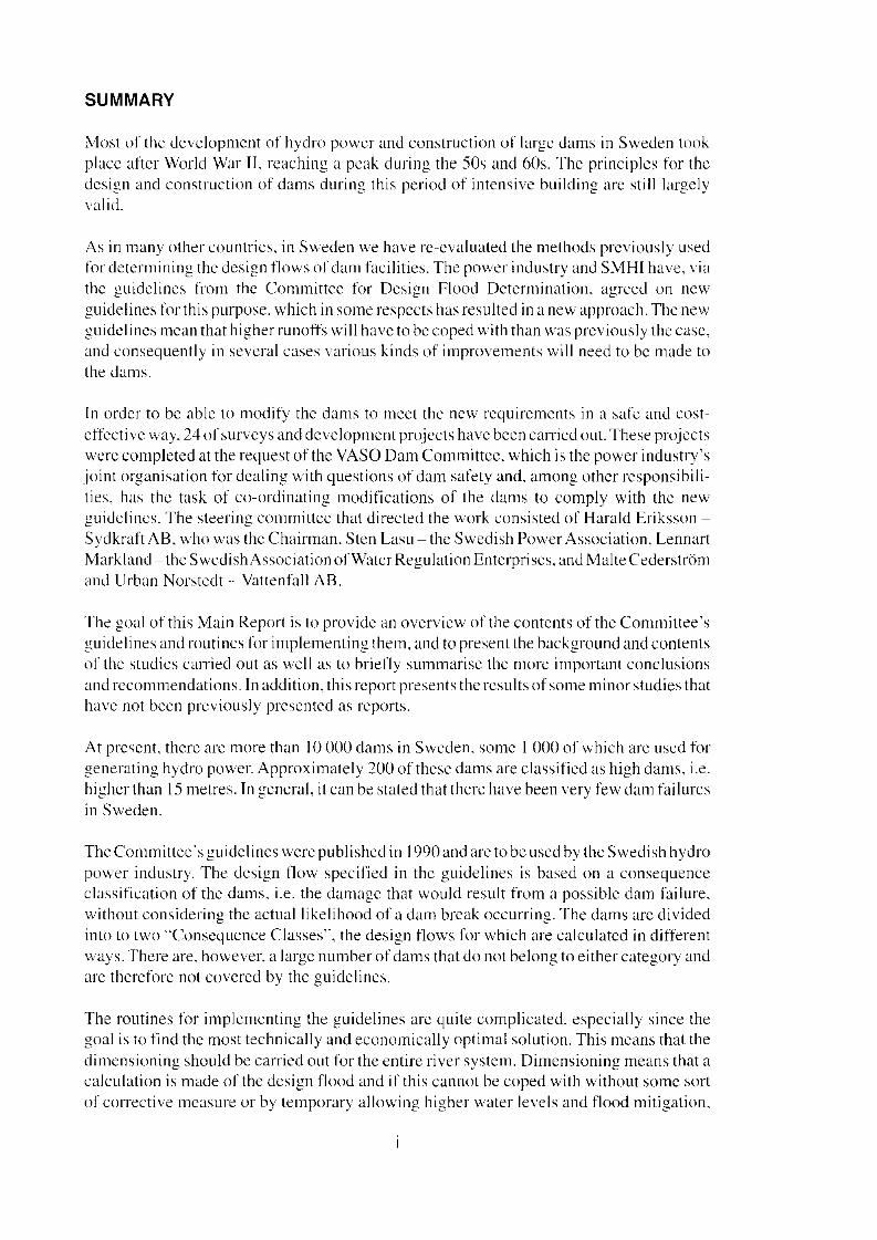
SUMMARY
Most of the development of hydro powcr and eonstruetion of largo dams in Sweden tookplace after World War II. reaching a peak during the 50s and 60s. The principles for thedesign and eonstruction of dams during this period of intensive building are still largelyvalid.
As in many other countrics. in Sweden we have re-evaluated the methods prcviously usedfor deterrnining the design tlows of dam facilities. The power industry and SMHI have. viathe guidelines from the Committee for Design Flood Determination. agreed on newguidelines for this purpose. which in some respoets has resulted in a new approach. The newguidelines mean that higher runoffs will have to be coped with than was previously the casc.and consequently in sevcral cases various kinds of improvements will need to be made tothe dams.
In order to be able to modify the dams to meet the new requirements in a sate and costeffecti ve way, 24 of surveys and development projects have been carried out. These projectswere compIeted at the request of the VASa Dam Cornmittcc, which is the power industry'sjoint organisation for dealing with questions of dam safety and. among other responsibilities, has the task of eo-ordinating rnodifications of the dams to eomply with the newguidelirtes. The steering cornmittcc that directed the work consisred of Harald Eriksson SydkraftAB. who was the Chairman, Sten Lasu - the Swedish Power Association, LennartMarkland - the SwedishAssociation ofWatcr Regulation Enterpriscs. and Malte Cederströmand Urban Norstedt - Vattenfall AB.
The goal of this Main Report is to provide an overview of the contents of the Committee 'sguidelines and routines for implementing thern, and to present the background and contentsof the studies earried out as weil as to brietly sumrnarise the more important conclusionsand recommendations. In addition, this report presents the rcsults of sorne minor studies thathave not been previously presented as reports.
At present. there are more than 10 000 dams in Sweden, sorne I 000 of which are uscd forgenerating hydro power. Approximately 200 of these dams are classificd as high dams. i.e.higherthan 15 ruetres. In general, it can be stated that thcre have been very few dam tailurcsin Sweden.
The Committee 's guidefines were published in 1990 and are to be used by the Swedish hydropower industry. The design tlow specifled in the guidelines is based on a consequenceclassification of the dams. i.e. the damage that would result from a possible dam failure,without considering the actuaI Iikelihood of a dam break occurring. The dams are dividedinto to two "Consequcnce Classes", the design flows for which are calculatcd in differentways. There are. however, a large number of dams that do not belong to either category andare therefore not covered by the guidelines.
The routines for implerncnting the guidelines are quite cornplicated, especially since thegoal is to find the most technically and economically optimal solution. This means that thedimensioning should be carried out for the entire river system. Dimensioning means rhat acalculation is made of the design flood and if this cannot be coped with without some sortof corrective rncasure or by temporary allowing higher water levels and tlood mitigation,

additional rcconstruction mcasurcs must be initiared in order to increase the dischargecapacity, for example by building a new spillway. Alternatively. raising the height of thedam and thereby permitting increased ternporary higher water levels. i.c, a tlood surchargeabove the normal watcr retention level can increase flood mitigation. The work involvcd in
determining the optimal solution is begun by prelirninary dimensioning the dam locatcdturthcst upstrcarn and noting any corrective action that needs to be taken. Thcn the next damis dimensioned, and this may affcct the dimensioning of the upstream dam. In this manner
the calculations are gradually performed for the cntire river. In order to arrive at thetcchnically/cconornically optimal solution. cost estirnates of the various possible alternatives are made. These alternatives are also compared in tenns of their benefits anddrawbacks. An optimisation programme has been dcvclopcd so that even with cornplicated
river systems it will be possiblc to find the optimal solution. For each river, a dimensioninggroup is responsible for carrying out all dimensioning work.
During the dimcnsioning work for a river it is important not to pay attention solcly to thespillways. hut also to limiting sections in the watcrcourse, especially since experience has
shown that there are orten other "narrow" sections in the watcrcourse that can becornelimiting during a high flood situation and this may affect both the Consequence Class andthe dimensioning. Ternporary tlood rnitigation can be eithcr passive or active. Passive tlood
mitigation implics keeping all the spillways fully open; while activc tlood mitigationinvolves actively seeking to incrcase the dampening hy having the spillways partiallyopened or entirely closed. Active tlood mitigation placcs particularly high demands on the
technical systems and on personnel and organisation. The c1assification process rneans thatthe consequences of a dam failurc are analysed, and in this context it may be ncccssary toculculare what happens in the area immediately below the dam, as well as how the tlood
wavc will move down along the river. Other aspects to be taken into consideration duringthe dimensioning work for a river are the effccts of landslides in river bluffs and oftloating
debris.
Each individual dam must be checked to see that it satisfies the requirements imposed as aresult of river dimensioning. In the case of embankrnent dams, this means the ability to
tolerate higher water levels than normal (a tlood surcharge), which among other aspeersinvolves issues such as the effects of waves, filters, internaI erosion, leakage and erosion inthe crest of the dam, as well as stability during increased leakage or waves ovcrtlowing the
crest of the dam. In the case of concrete dams. this concerns. arnong other aspects, stabilityand in some cases the ability to tolerate overtopping. In general. mcthods for hot h
monitoring and investigations are needed.
The spillway is of fundamental importance with respect to flow adaptation. It is particularlyimportant that the assumed discharge capacity actually exists and that the spillway gutes canrcally be opened when needed, or in other words that thcy have a sufficient level of
functional safety. The dimensioning work is expected to result in the indication of a needfor additional discharge capacity at a number of dam sites, which usually means choosing
a conventionaI spillway with gates. A conceivable alternative could be some form ofvIuseplug", for exarnple an erodible section of the dam. In the guidelirtes. it is assumed that the
power plant will be shut down during a high tlood situation and that the turbine water will
no longer help to discharge the follow, Through the use of special mcasurcs, however, it maybe possihle in some cases to safely use the turbine waterways to discharge water.
II

In addition to the design Ilood, dam safety dcpends on a great many other factors, It is vitalthat all such factors should maintain the proper level of safety. A useful tool in this respeetis a risk analysis.
In all the above areas, investigations have been earried out, whieh are included in the reportseries and are brietly described in this report.
An overall conclusion is that it is very irnportant that the work of eomplying with the newguidelines is performed in a responsible and competent manner so that the inerease in thelevel ofdarn safety, whieh was the airn of the work carried out by the Committee for DesignFlood Determination, is actually attained, It is our hope that the surveys and developmentprojeets earried out will eontribute to this end.
\/,4.S0 Dam Committee
iii


1. NEW SWEDISH GUIDELINES FOR DESIGN FLOOD
1.1. General
As in many other countries, in Sweden we have re-evaluated the methods previously usedfor determining the design flows of dam facilities, The power industry in Sweden and theSwedish Meteorological and Hydrological Institute. SMHI have. through the work in theCommittee for Determination of Design Flood (the Committee), agreed on new guidelinesfor this purpose. which in same respects has resulted in a new approach.
The new guidelines mean that higherrunoffs will have to be copcd with than was previouslythe case, and consequently in several cases various kinds of improvements will need to bemade to the dams. lf thcse improvements and combinations ofmeasures are not planned andexecuted in a careful and competent way, major economic resources can be wasted withouthaving attained the desired increase in safety.
Inorder to cope with this complicated adaptation process, compctence and knowledge arerequired within the following areas: hydrology (possible runoff), engineering (includingactual discharge capacity, narrow sections, floating debris, technical capabilities for dealingwith flood surcharge. safety of gate functions. and methods for examination and monitoring). reliable operation interaction, failure impact and preparedness, and risk analysis.Generally. it can be statcd that an extreme flood situation results in problems that aredifficult to prediet since expericnce is, by the very nature of the event, difficult to come by.
For those facilities where, for exarnple, additional discharge capacity must be created, it isimportant that the measures be designed with the greatest possible consideration to theabove conditions. For those facilities deemed not to need reconstruction or conversion. itis of course necessary when making this determination to take into consideration thedifficulties that may arise during an extreme tlood situation.
After an analysis of requirements, the Dam Committee of VASO, the Swedish Associationof Water Regulation Enterprises, initiated a number of survey and development projects inorder to further clarify and increase know-how within certain areas. A working group forhydrological development work within VASO, called VASO/HUVAhas conducted similarstudies within the hydrological field.
In this Main Report, the contents of the Committee for Design Flood Determinatiori'sguidelines are briefly described, as is the compliance process, and a summary is given ofthe projects included as weil as their background. The report has been divided into a generalsection, and a section covering the factors effecting the river dirnensioning, and a sectionon the factors and requirements that are applicable for the individual dams. The report alsoaddresses risk analysis, and briefly the research and development within the area of damsafety and organisational issues from a dam safety point of view. (Some of the reportsincluded in the series are not only related to the adaptation of the Committcc's guidelines,but are of a more general nature and have been deerned to be especially important forconsideration in connection with pending increases in safety Icvels.)
1
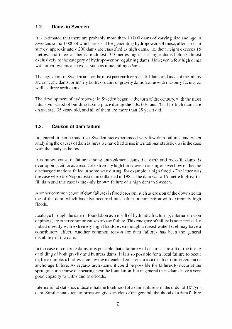
1.2. Dams in Sweden
Il is estimated that there are probably more than 10 000 dams of varying size and age inSweden, some I 000 of which are used for generating hydropower. Of these, after a recentsurvey, approximately 200 dams are classified as high dams. i.e. their height exeeeds 15ruetres. and three of the m are almost 100 metres high. The larger dams belong almostexelusively to the category of hydropower or regulating dams. However, a few high damswith other owners also exist, such as mine tailings dams.
The high dams in Sweden are for the most part earth or rock-fill dams and most of the othersare eonerete dams. primarily buttress dams or gravity dams (some with masonry faeing) aswcll as three arch dams.
The development of hydropower in Sweden began at the tum of the ccntury, with the mostintensive period of building taking place during the 50s. 60s, and 70s. The high dams areon average 35 years old. and all of them are more than 25 years old.
1.3. Causes of dam failure
In general, it can be said that Sweden has experienced very few dam failures, and whenanalysing the eauses ofdam failures we have had to use international statistics, as is the casewith the analysis below.
A common cause of failure among embankment dams. i.e. earth and rock-fill dams. isovertopping, either as a result of extremely high flood levels eausing an overflow or that thedischarge funetions failed in some way during, for exarnple, a high tlood. (The latter wasthe ease when the Noppikoski dam collapscd in 1985. The dam was a 16-metre high earthfill dam and this case is the only known failure of a high dam in Sweden.)
Another common cause of dam fai lures is tlood erosion. such as erosion of the downstreamtoe of the dam. which has also occurred most often in connection with extremely hightloods.
Leakage through the dam or foundation as a result of hydraulic fracturing, intemal erosionor piping, are othercommon eauses ofdam failure. This category offailure is not necessarilylinked direetly with extremely high floods, even though araised water level may have acontributory effect, Another common reason for dam failures has been the generalinstabil ity of the dam.
In the ease of concrete dams. it is possible that a failure will occur as a result of the tiltingor sliding of both gravity and buttrcss dams. Tt is also possible for a loeal failure to occurin. for cxample, a buttress dam owing to leached conerete or as a result of reinforcement oranchorage failure. As regards areh dams. it could be possible for failures to oecur at thespringing or because of shearing ncar the foundation, but in general these dams have a verygood capacity to withstand overloads.
International staristics indicate that the likelihood of a dam failure is in the order of 1O'4/yr.dam. Similar statistical information gives an idea of the generallikelihood of a dam failure
2
in terms of the various types of dams. But the safety of a specific dam cannot be based onthis typc of general data.
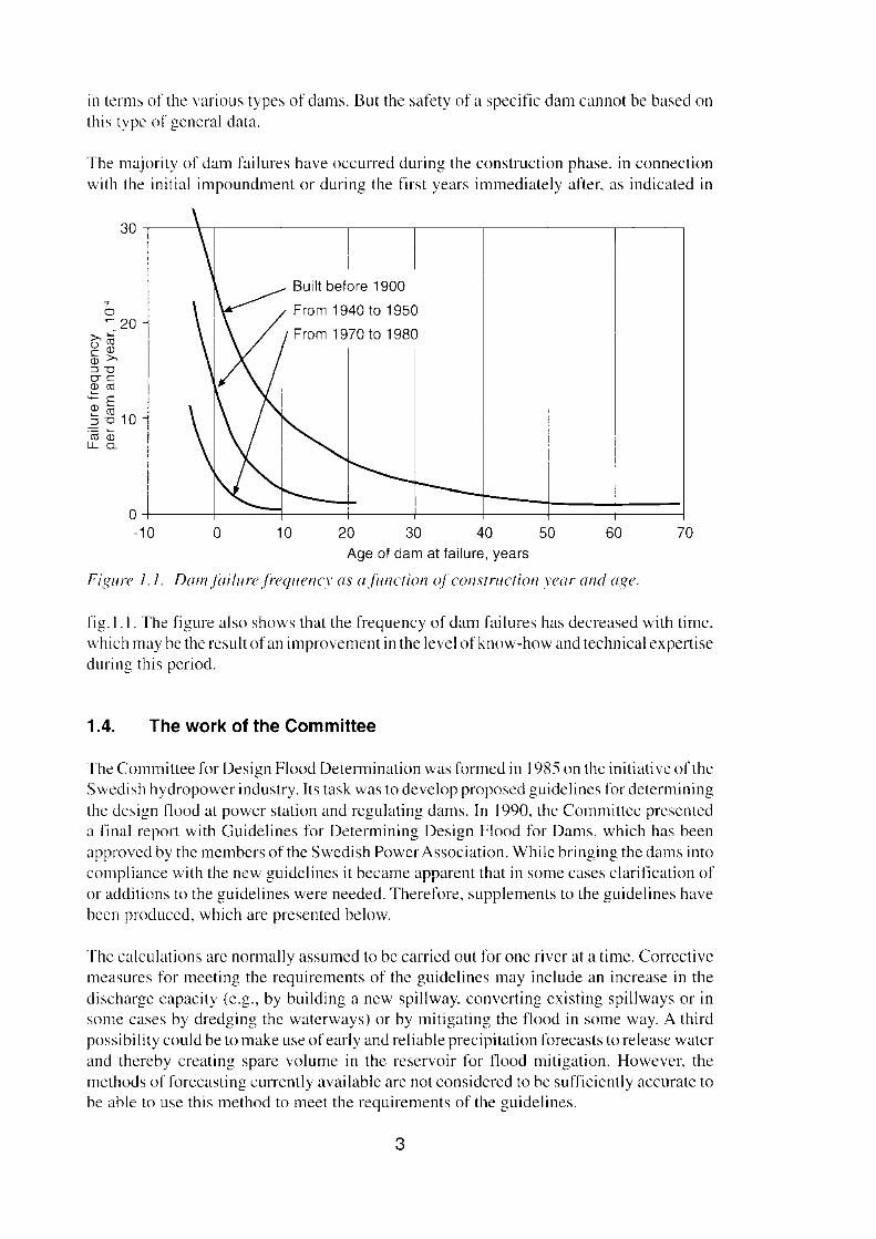
The majority of dam failures have occurred during the construction phase, in connectionwith the initial impoundment or during the first years irnrnediately after, as indicated in
30 -,------\---,--------r----,--------,------,---r-----,---------,
From 1940 to 1950
From 1970 to 1980
706010Oot----J~~::::::t_-t_=t===i====i=~-10 20 30 40 50
Age 01 dam at lailure, years
Figure 1.1. Damfailurefrequency as afunction ofconstruction year and age.
fig.l.l. The figure also shows that the frequency of dam failures has decreased with time.which may be the result ofan improvernent in the leve! of know-how and technical expertiseduring this period.
1.4. The work of the Committee
The Committee for Design Flood Determination was formed in 1985 on the initiative of theSwedish hydropower industry. Its task was to develop proposed guidelines for determiningthe design t100d at power station and regulating dams. In 1990, the Committee presenteda final report with Guidelines for Determining Design Flood for Dams, which has beenapproved by the members of the Swedish Power Association. While bringing the dams intocompliance with the new guidelirres it becarne apparent that in sorne cases clarification ofor additions to the guidelines were needed. Therefore, supplements to the guidelines havebeen produccd, which are presenred below,
The ealculations are normally assumed to be carried out for one river at a time. Correctivemeasures for meeting the requirements of the guidelines rnay include an increase in thedischarge capacity (e.g., by building a new spillway, converting existing spillways or insome cases by dredging the watcrways) or by mitigating the flood in sorne way, A thirdpossibility could be to make use of early and reliable precipitation forecasts to release waterand thereby creating spare volume in the reservoir for t100d mitigation. However, therncthods offorecasting currently available are not considered to be sufficiently accurate to
be able to use this method to meet the requirements of the guidelines.
3
In order to permit flood mitigation in the existing dams (Consequence Classes I and II), theCommittee's guideIincs aIIow departures to be made from the requirernent, to be able todischarge a flood with a return time of at least 100 years at the normal retention leve!.Therefore, with respect to dam safety, a design flood may be discharged at a water levelexceeding the retention water level, i.e. asurcharge occurs. On the initiative of theComrnittee, the Water Rights Act has been supplemented with the right to make thesurcharge under certain circumstances and make the economic settlements for damagesafterwards.
1.4.1. Consequence c1assification of dams
The Committee was of the opinion that the damage which can be eaused by the failure ofa dam should initiaIIy determine the consequence c1assification (which then was caIIed therisk c1assification) and thus also the demands govcrning the design of the dam. The designflood according to thc guidelines is therefore based on what is in the guideIines referred toas "risk classification" of the dams, but with the terminology that has subsequently beenestablished, "consequence classification" would be a more accurate term and has been usedin this report. The c!assification is based on the damage which a conceivable dam break atacertain dam would be able to cause, but does not on the other hand deal with the probabilityof a failure taking place in the dam. Tt is thercfore not the probability of a dam breakoccurring at a ccrtain dam that determines the class, but only the consequences that wouldoccur if the dam did fai!. The Committee has defined two Consequence Classes, but thereare also a large number of dams which do not belong to cither of these and which thus arenot affectcd by the new guidelines.
During classification, it is important to nate that the c1assification is based on the marginaleffect of a dam failure, i.e. the inerease in the damage to the surroundings which the collapseof the dam eauses in addition to the damage that the exceptionally high water flow wouldanyway have eaused. even if the dam had not collapsed.
Consequence Class I- Non-negligible risk to human life or other bodily injury;or- Considerable risk of serious damage to important traffic route, dam structure or
other similar installation, or to an important feature of environmental value;or- Clear risk of major economic damage.
Consequence Class IINon-negligible risk of damage to major traffic route, dam structure or equivalent installation, feature of environmental value or property belonging to a party other than the damowner in other cases than those specified for Consequence Class I.
The Committee maintains that the assessment of which Consequence Class a certain damstructure should belong to must be determined from case to case in the first instance by thedam owner but ultimately by examination in accordance with the Water Rights Act. Sinceit is the consequences of the damage that detcrmine the consequence classification, it is
4

impossible to rcfcr different types of dams (embankment dams, conerete dams ctc.) to aparticular consequence class.
1.4.2. Design flood
The guidelines of the Committee deal with both new and existing dams, between whiehthere are certain differences. The present report deal s in the first instance with existing dams.As regards the exact content of the guidelines, reference is made to the guidelines inquestion.
Design flood for Consequence Class IThe determination of a design tlood for dams in Consequence Class [ sha!! be simulated byapplying an accepted hydrological modeI in the fo!!owing summarised basic steps:
I. The model is calibrated against existing runoff series (at least 10 years).
2. By means of frequency analysis, snow storage with a return time of 30 years arecalculated. This value is entered in the modelon the last date on which the snow coverculminates during one of the years analysed.
3. The design 14-day precipitation according to the Cornmittee's guidelines is adjusted forelevation, year and area.
4. Regulation strategies incorporating the Cornmittee's guidelines, storage data dischargecurves and water conservation regulations are entered in the model, In this context.consideration sha!! be given to the fact that only spillways that can be put into operationat short notice and with fu!! safety are to be included. The storage is assumed to havereached the maximum water level by I August and is not assumed to decrease in leveluntil the critical tlow period is over. Any discharge possibilities through power stationturbines may not be included from and including the 9th day of the precipitationsequence. The VASa Dam Committee recommend that in those cases where measuresmust anyway be carried out in order to cope with the design flood, the dam should beadapted to and be independent of whether turbine discharge is available or not.
5. The design flood sha!! be determined by simulation in the model for at least 10 yearsbased on the latest available year 's climatic data. In the simulation, the 14-dayprecipitation is advanced one day at a time from the date specified in item 2 above. Thesimulation that gives the highest water level in the year series according to the previousparagraph wi!! be the design tlood occasion.
6. The wind-impact is determined and added to the design water level in aecordance withitem 5 above.
In addition, for dams of Consequence Class I there are supplementary conditions whichmean that the discharge capacity of the dam at the water retention leve I shall normally besuch that a tlow with a return time of at least 100 years can be discharged. Exceptions to thisrnay be permitted after Water Rights Court determination, for example if a permit is grantedfor tlood surcharge.
5
Design f100d for Consequence Class IIFor dams in Consequence Class II, the tlow with a return time of at least 100 years isdetermined by means of frequency analysis byexisting hydrological material (runoff,natural water tlow or regulated water flow),
1.4.3. Supplements to the Committee's guidelines
During the course of the Committec's work, it was predicted that it might be necessary tosupplement or adjust the guidelines, as weil as instructions for the application of theguidelirres in special cases. The powerindustry had already atthis stage appointed a workinggroup. the VASa Dam Committec, with the task of preparing and following the con versionworks and tlood mitigation measures that could be the consequcncc of the new guidelinesfor design.
The continued work on the adaptation of Ilows has warranted the provision of certainadditions and changes to the guidelines, which have been made in consultation between theSwedish Meteorological and Hydrological Institute, SMHI and the Swedish power industry, represenred by the VASa Dam Committee. The govemrncnt has been notified of theconsultation. The additions decided so far are:
Supplement 1:The supplement concerns the consequence c1assification with respects to the consequencesof high flows and establishes that the marginal effect (damage) of a possible dam slide isdecisive for the classification.
Supplement 2:The supplement concerns a change in connection with wind velocity for determining therequired free board.
Supplement 3:The supplement concerns a change in the instructions for calculating the flow for new damsin Consequence Class II and involves the deletion of points 2 and 3 in the guidelines.
1.4.4. Return time
When the probability of a certain years maximum (Q",,,,) being exceeded has beendeterrnined, the so-called return time for this value can be calculated:
lT=
P
where T =return time for QIIWX
P =the probability of Q""" being exeeeded
In design calculations reference is often made to l OO-yearflood, lOOO-year Iloodetc. Returntime may, however, be unsuitable to use since it is easy to be tempted to believe that if thelOO-year tlood occurred last year it will take some 100 years until the next time there is asimilarly high flood. The probability of a 100-year flood during a certain pre-determined
6
ycar is of course according to the theory just as high irrespectivc of when it last occurrcd.
Il is also possible to calculatc the probability of a certain year max. Q being exceededII1ln
during a certain period, for example a 10, SO or 100-year period.
P" = J -(J-JfT!" = J -(J -p)"
where p = probability that Q is exceedcd durinz an n-year period./I II/al ~.
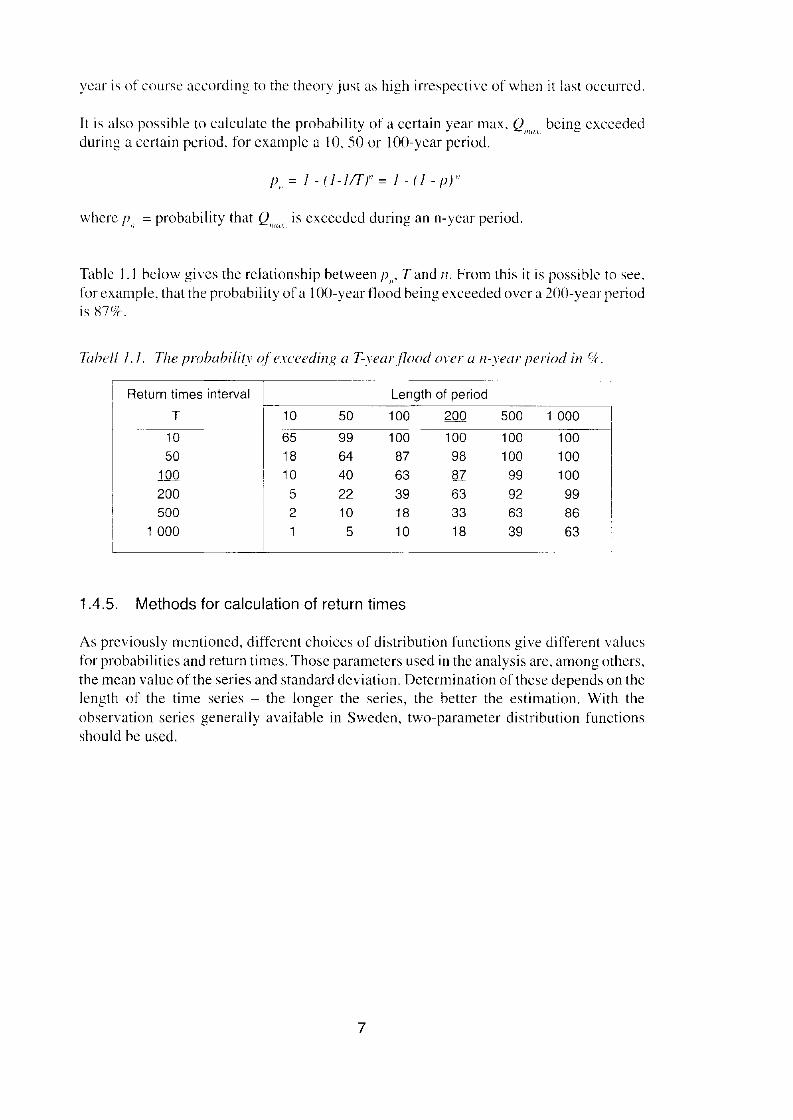
Table I. I below gives the relationship between P", T and n. From this it is possible to see,for example, that the probability of a IOO-year tlood being exceeded over a 200-year periodis S7o/c.
Tabell 1.1. The prohability o] exceeding a T-yearj7ood over a n-vear period in clr.
Return times interval
T 10 50
Length of period
100 500 1 000
1050
100200500
1000
65
181052
1
9964402210
5
10087633918
10
1009887633318
100100
99926339
100100100998663
1.4.5. Methods for calculation of return times
As previously mentioned, different choices of distribution functions give different valuesfor probabilities and return times. Those parameters used in the analysis are. among others,the me an value of the series and standard deviation. Determination ofthcse depends on thelength of the time series - the longer the series, the better the estimation. With theobservation series general ly available in Sweden, two-parameter distribution funetionsshould be used.
7

8
2. APPROACH FOR IMPLEMENTATION OF THE COMMITTEE'SGUIDELINES
2.1. General
The Comrnittee's guidelines involve a relatively complicated approach to design work,especially when the goal is to discover the optimal technical solution. The approach isdescribed below.
In order for the work in connection with adapting the dams to the requirements of the newguidclincs to take place in an optimal way with respect both to safety and to econorny, thedesign work must be carried out jointly for all installations on a river. This means that it ispossible to Iind a more optimal solution than without further analysis increasing thedischarge capacity in all facilities, where it is insufficient to allow the water to continuedownstrearn, which would involve bot h high costs as weil as scrious damage as a result offlooding and erosion etc. An optimal solution of this kind may mcan that larger waterreservoirs are used to mitigate the flows, which can be don c either by not fully utilising theexisting total discharge capacity (active flood mitigation) or by deciding not to increase thedischarge capacity. This does not only mcan an optimisation on the part of the powerindustry but the flood mitigation may also be desirable for the sake of society sinceconstruction carried out on behalf of society often takes place in such away that extensivedamage has already occurred for flows that are considerably lower than those for which thedam spillways are currently dimensioned. This in tum depends on shortcomings incommunity planning but also on the fact that society in general is designed for considerablylower Ilows than the dams. At the same time it should be pointed out that active Iloodmitigation should not be carried out for any purpose other than for securing dam safety andthen in accordance with a plan prepared for the river. since otherwise (e.g. if active tloodmitigation took place to avoid downstream f1ooding) there would be an encroachment onthe capacity of the dam to cope with high tlows. The margins would in such case alreadyhave been utilised (at least partly) if the extreme case occurred.
If the design f100d cannot be coped with by surcharge and tlood mitigation, reconstructionmeasures must be taken to convert the structure in order to increase the discharge capacity,for example the construction of new spillways. Alternatively, the dam can be raised, whichgives a certain increase in discharge capacity in the existing spillway and at the same timernay lead to increased tlood mitigation.
The discharge capacity of a dam referred to in the guidelines docs not merely mean therelease capacity of the spillways; consideration shall also be given to the effect of otherlimiting sections and other possible obstacles to water runoff.
In certain cases convertingexisting spillways, often by lowering the spillway thresholds cancreate an increase in discharge capacity. By replacing older shut-offdevices that are difficultto operate and maintain by modern, easily operated gates it is possible at the same time toincrease the functional reliability and permit a quicker increase in discharge. Sornetimes,dredging or enlargement of the waterways below a dam rnay be a sufficient measure toincrease the discharge capacity. Finally, new spillways can be constructed in or alongsidethe existing dam, for example in the form of a free overf1ow weir, surface spillways closedby gates, erodible dam sections, labyrinth weirs or siphons. A previous investigation onthese issues is presented in the report, "Increased discharge capacity in existing dams" [5].
9

l, ~<f '" "nY n.. , ,1>0: ......t.. n",","",n'<.I J<,,~" P''"I'' h."" ""'" ............. "uh,·..n~"," ,.;" in h~ .h""'n. h~d"..Ii< ...~, ,,,,,,nn~ . 'l"'''''"'''....t ".,,'" fi~m, 1<~;, I'Ii"". II",o< ",.,~ ,"'..., w."" '"~ ~n..I"'" &"rrn"," '" ,"" I\cr "" "",,., >hd ,l><" ""Il"." '""" 'I'" ",· >th '"" .....'f" ","" pf '''' ~l><,l><,. ""I ", '" "" .. "m_ ,l>< "''''~ .... "I"'-'u, 01 ,ho.'....""..~, 0=1"" .. ,"'.,." ..... ,~ ,1><"",... c"''' " , ..... n.,.•," ... 'nnod,,,, ""~ t ,"u.hl<....-hn', . 1.."I """"",, ,e ,..m"m..." .. lo.- t .. "n' ;", n,,,, ',"'I<m 01 "".....'<l d.s<h"'l"""F''''''; ,nd '.01'" f,.-m, .. f flo .., ... ; " ~... ,,,"
In. f."" <I>l!".• J<-,,~n ",",>If ',,"1 ,h<<10>", ,.. ,h< n'''' " ..",,1.,«1 .." ,I>< t>;."",~ ,'"~ ...... "«I '''''' ""m,"«...h,d, "",..., ,h" ""," d>m ..... '1"11 ..·., " .""",,,d~. I>< "'''',.. "''I'" "'u" ,h< ,hi~n ,m.,ff. In .. "'-,,..] ""I''' i, i, d<c-ide~ ,,"ich du.., hol'" ,.10<mod,flro ," ,_n,,,·,,,,,, "'nh ,"" ..... ,."' ""' .... ,"'''"~ ,',"'.horn. ..".-,,,.,,"~ ,I>< ~,,,,·ll ,,,'"f'.'"'';',''''' ",..h",.. ,," "fI~~h,. """n, "1"''''''''' in ,o" m<r. Ar'er"""h ...od,t"' ..., ..... ,·.k..I", ... i, ,'..".,.1 ..., I.w ,I>< n,c"<. I" , .....' ~I><"" [h< ,<>j.. ;" .... pf",.j m,,',., ...'"""'. b< .,:hK'N. ,..... ,., fIo ~,.j m,..~...... ""'Y '" "'''mpl<"<! '" "."' •• to" "r"""n.",,"" ~',"" fIo.><l mui!",i.." in ,ni, """"" """"' ,h... ,n ;"" . 11. ,;,... "rKI« .. "i~htl".. "' k'" .~ .., "'....... II, n,""",um .h",·"',P' C'I"'-·II~. H"",.. ,, _III ,.dc, Ou find , ....
$Y$lEMOllEROE.. DE
..--__,,-DiI,."....'*'''-.'-
SYSlEMBEROE.. DE
'--g _....._""'.----Ol
,~
',,", ' ..-l
--------
I•
:10-1"-.... -.--- -'lM O O e L , • e , • , M M ,...
~~E ..~E~.NOE'LOOf...~ 'SKf,",o.< ""''''''''...l,TG.O."OSFOf<SI.AG
optimal solution. a cornparison should be made between alternative solutions. on the basisof which the most suitablc technical/cconomic measures for the entire river can be finallybased,
2.4. Strategy modeiOS
Active flood mitigation should only be necessary in more complicated watcrcourses, inwhich case the pertormance of the calculations will be much more cornplicated and asimulation mcthod will be needed. An optimising program/a stratcgy modeI referred to asQS has thcrefore been developcd which can be used as an aid in finding a technical!econornical solution.
During the design work. sensitivity analyses should be carried out so that a solution is notehosen that does not function satisl'actorily if. for examplc, the spillway capacity for thespillways in a dam is in actual Iact sornewhat greater than assumcd and for the downstreamdam sornewhat lower.
QS modelThe model is a pure now regulation model that is fed with local runoff values basedon measurerncnts or hydrologicul model calculations. The basic concept is that themodel shali, in each step in time, use information available on the river to select thebest flow-flood mitigation measure. In those cases where tlood mitigation is notpossible, the model can be equatcd with the regulation section of, for example, theSwedish "Hb v-model". However, in QS a sub-area can have two outlets withdifferent addresses,
In the strategy model, critical water levels are specifled for each dam, which shouldnot be exeeeded. Before a eritieal water leve! is achievcd at any of the dams. releaseis controlled completely in a predetermined way with required production releasesand current discharge capacity at the various installations. After each step in time, themodel studies, starting furthest downstream in the river. whether a critical water levelhas been reached and thus whether Ilood mitigation needs to be carried out before thenext stage. If so, the model calculates, on the basis of the runoff forecast for the nextstage, the maximum releases that are allowed from installations situated furtherupstream. Inthe first instance, the model attempts to mitigate the flow in the reservairsituated immediately upstream. If the critical water level has also been reached here,the tlood mitigation requirement is moved one stage further upstream etc.
The model not only provides the possibility to analyse suitable flood mitigationreservoirs in connection with tlow design calculations but may also be a planning aidin acute tlow situations.
The model and manual have been produeed within the framework of the report series andare therefore available to the Swedish hydropower industry. They have been preparedjointly by Vattenfall Utveckling AB and Vattenfall Hydropower AB.
11
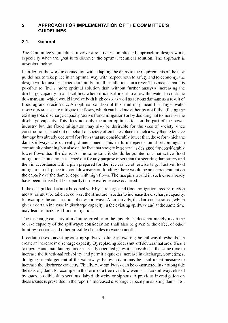
2.5. Legal and economlc aspects
Once the WUJ 'in" :;roup for" I'h er has 1:0111 111"1<:0 " ' work and the Jl.mcr :11111 I't'gu1:I I,oncumpanic-, 1:01lel:l'II<:J have acccprcd the , lutlon, il shall norrnally he prevenred and, ifrequired hy the '"huil111.1", esr.1" 11, heJ in "'Ille f"rll1 b~ the Wal r Ri1!hL, COUI1 , Dercollin):on the nature 01111<: sulution, Ihl\ i, j udgcd Il' I able In uike 1'1 , C" on a cunuuun ha, js rorthe entirc n v I' nr tor on lI1.h \"ld,,;11dam al . 1 lim e. in which '[1I1te\ L. howcver, the ovc all, ilU;l1l0 11 vho uld be prescu ted In il suirablc wuy Cc rtnin measnre« , for e "011'1,, Tilising theheil:' 1I 1nr Ihe 11111 ' 1'\ II'U, corc without the d.rrn o therwi-e being chunged. ma ' invulve asimplified approuch,
TII"texts Ihil' h" \" e been udded to the \\';11 er I(Ighl ' Act 111 connerrinn \v itllthe rigtu inccrtuitI
ca,c' to ' UJ ,hllrg.: III .1' 1111 with th... uim n' pmlcc tll1 j1 .1,1.m'Il'lre" 1d.uu ur J um.' "nu Incumpensate for the dumage " fler the evem ' '' PJ"m Ihe UJ";I thut 111"1,, i.• II" ..Ihe' pal1~
L" I ice rneo,
In ccnain ense s. il m:l~ be considere d ratio nal to implcrucnt mc.l>ure, lm Il J am in order 1llIl "';cl ~llmC Illh~ r Jl.Ul ~ trum Il lluw, vhich the laner cnnnot wp.' with, Here, of et ur-e ili, the responvihility n r III owners of the dams 10reach an agrcement on .1, "I Uli llll Df IhisI)'I"" :lIld the r; II1lll LlaI cDmpeuxuu un fllr hoth the reconstrucnon mcasures and for v [lCr.l l ionand rnaintenancc cos r- a, we ll il S produc tiou lu,,,",, connec ted '" uh iI.
The n-vised liabilhy , iluulttll' lhal nC\\ Icgisla[ion ' Ilneerning "stri t linbi lity" Ii.c, the d.uno wne ha' the full respom ltlllil)', irrc-pecuv . Df", hether he \l " , 11 ').:liJ.:"ru o,' not) involvesma necd I••tie considered in onncci ion with design
Tbe A 'O L 'gal ornnuuee handle-, legal muners 111 " LJ lIIleCLiu/J with adaptauon t l l theCemmittcc's gulde lmes
Figurr 3,1. 711<' photo uuph shows hcad I...u t'.> rtf"/r,'wll [mm Slll.~Jm l'o...rr Plun t iIIhiKizj1011" cond i tious , TI,,' /0 ,' ,"' ,\ <In' " .\llrlit'lIr'rd III/",'r, l /U' bridg» mu] (1Ir1/U'"
111',1'/0 '(11" 1/" "" '" P r/1"1 orI' ;I'II/r,, ).
12

3. INVESTIGATIONS CONCERNING THE DESIGN FLOODDETERMINATION FOR A RIVER SYSTEM
3.1. General
When designing a river system, consideration must be given both to factors that aredependent on the river as weil as to the preconditions for each existing dam in the riversystem. A presentation is given below of studies that primarily concern the river.
During design work, and particularly when selecting the optimal solution, it is of courseimportant that the basic assumptions are correct, for cxample that dams which are assumedto be surcharged can actually withstand this and that the spillways actually have the capacityassumed. This rueans that oncc a preliminary design has been made a careful check mustbe made for each dam to ensure that it meets the requirements imposed on it by the solution,or that modifications to rneet the requircmcnts imposed are possible and their costsacceptable. Alternatively. the design work shall be repeated, i.e. a different or modifiedsolution should be developed.
The design tlood aecording to the Comrnittee has been judged to have a return time of at least10 000 years, and during check calculations for a tlood of this magnitude there is not thesame need for safety factors conccrning, for exarnple, loads as with a more common loadcase. Besides this design flood, a tlow with a return time of 100 years shall be combined witha higher wind velocity than the Comrnittee's design tlood and it is not necessarily clearwhich case will be the decisivc load case, so for example, for an upstream slope, a checkmust be made for both cases. AIso cases with a sudden shutdown of the turbines, wherebythe turbine water tlow is to be discharged through the spillway, may be possible and thedischargc capacity must in such case be sufficient and, depending on the rate at which thewater rises in the reservoir, perhaps rapidly available. In such cases it shall normally bepossible to cope with this by only using one of the gate systems, i.e. AC or DC-operatedgates. An analysis should also be made of the consequences of incorrect operation of gatesin upstream dams. If a critical situation could occur from such gate operation, measuresshould perhaps be taken to prevent an unintentional opening of this kind.
A description is given below of certain factors that have proved to be of particular interestin connection with design work and the studies on these subjects,
3.2. Limiting sections in watercourses
Expcriencc shows that there are often other sections in a watercourse apart from the damsthat serve as hydraulic contral structures for flows generated in a high-tlood situation. Thisaffects both now design and consequence classification of the dams.
3.2.1. Influence on Consequence Class
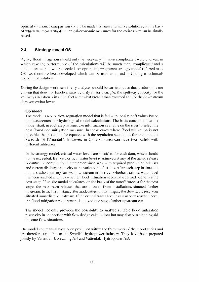
A naturally narraw section (or limiting scction, i.e. a section with steep hydraulic gradient,for instanee a critical section) upstream of a certain dam may, for example, restrict thevolume ofwater released in connection with a dam failure (see fig.3.2) and which continues
13
BEFORE CONSTRUCTION
Water level at high flow
Threshold
AFTER CONSTRUCTION
Water level at normal flow
Water level at high flow
I
Water volumenot released atdam failure
Threshold
Water volumereleased atdam failure
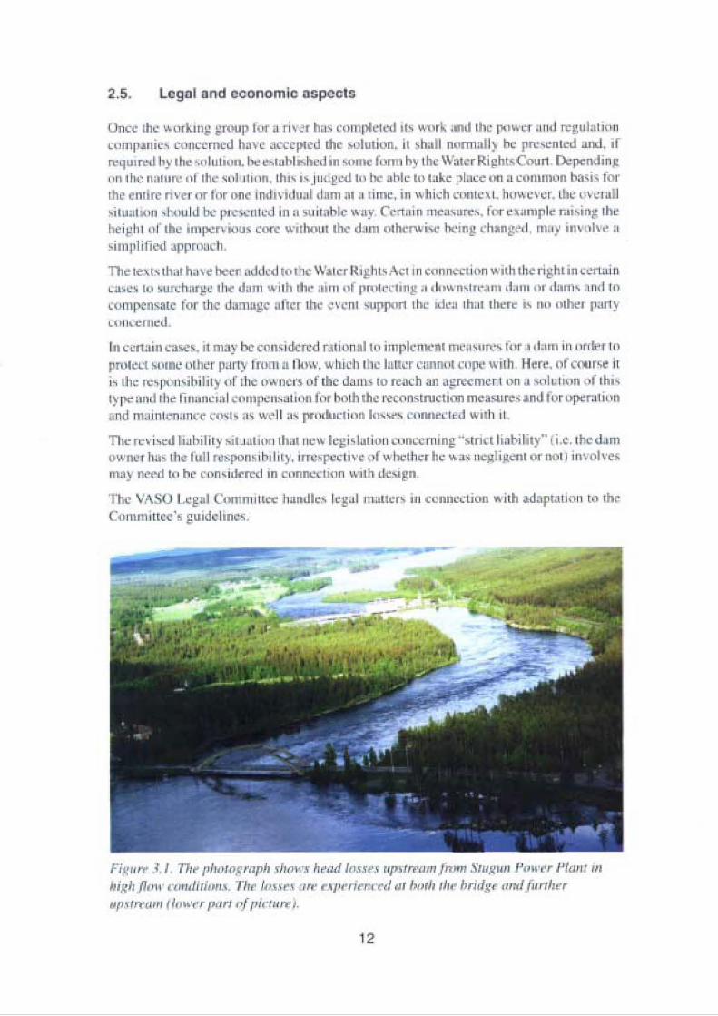
Figure 3.2. Example. The figure illustrates how a thresho Id. if it is a critical section athigh flow, can restrict the water volume released in case ofa dam failure.
to the next downstream dam so much that the latter dam can cope with the situation withoutcollapsing.
3.2.2. Effect on the design
A natural narrow section upstream of the spillway in the vicinity of a dam means that thewater level will rise more than it would have done if this section had not existed before thebalance is achieved between runoff from upstream of the narrow section and the dischargethrough the spillway. This means that flooding may occur upstream of the limiting section(see fig. 3.2) and it is of course necessary for this to be known when calculating the waterlevels that would occur during the design flood. Subsequently, a check must be made thatthe system can withstand these water levels (particularly upstream of the narrow section).
A limiting section downstream from the spillway can in certain cases reduce the dischargecapacity by backwater effects, which means that the calculated discharge will not occur untila higher reservoir level is reached than otherwise.
It is worth noting in this context that flooding upstream of a naturally narrow section doesnot normally have any connection with the existence of the dams downstream but dependson the high flowas such.
14
BEFORE CONSTRUCTION
Water level at high Ilow
I~
I...J
AFTER CONSTRUCTION
Water level at normal flowWater level at high Ilow
SECTION I-I
I~
Water retention level(normal water level )
Threshold
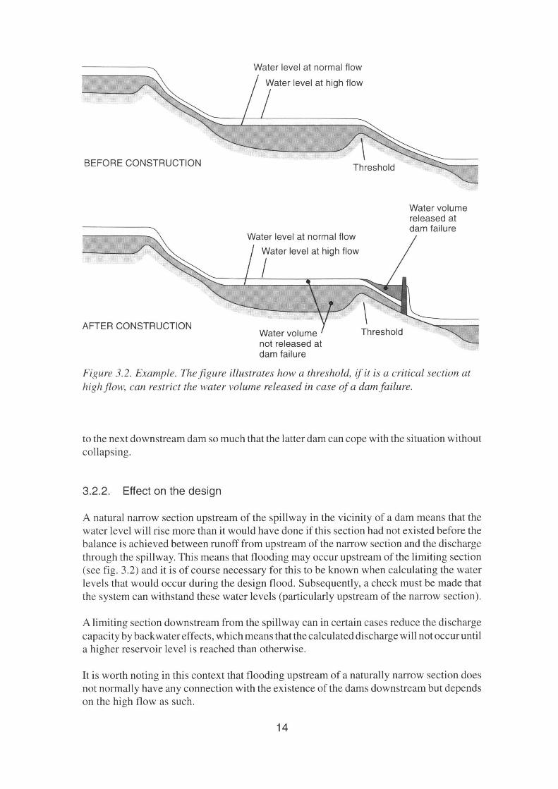
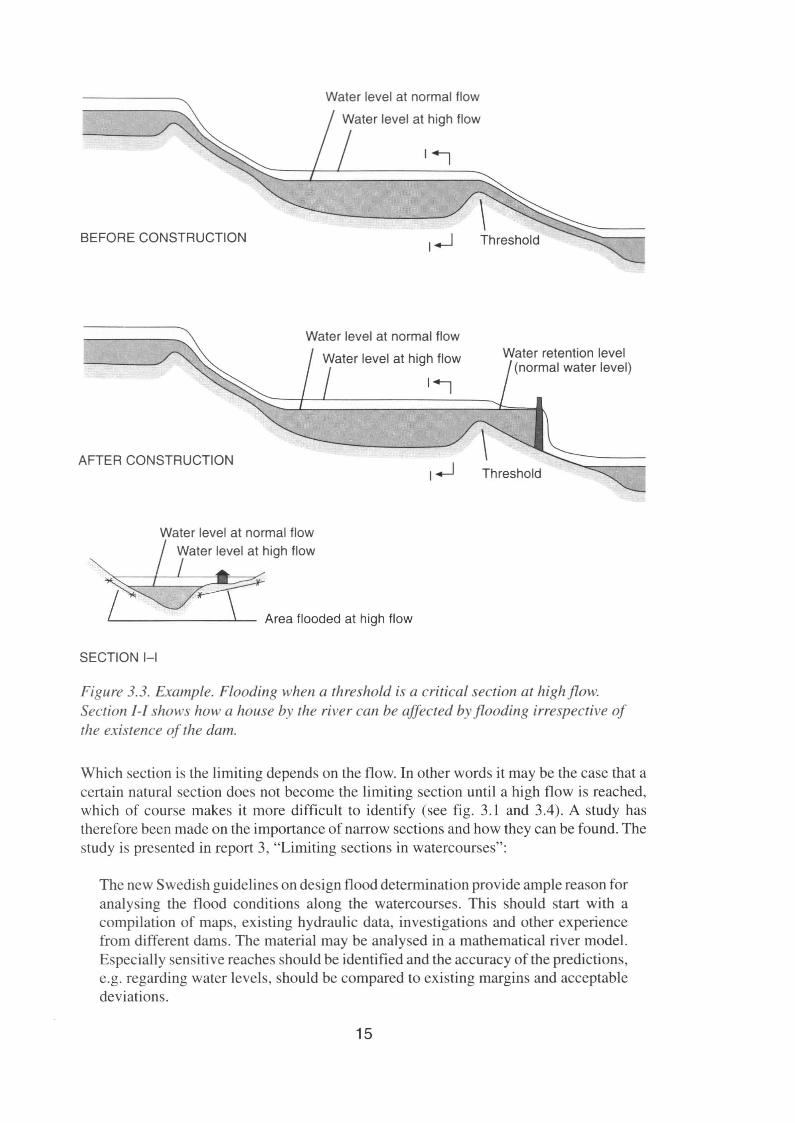
Figl/re 3.3. Example. Flooding when a threshold is a critical section at high flow.Section I-I shows how a house by the river can be affected byflooding irrespective ofthe existence of the dam.
Which section is the limiting depend s on the flow. In other word s it may be the case that acerta in natural sec tion does not become the limiting sectio n until a high flow is reached,which of co urse makes it more difficult to identify (see tig. 3. 1 and 3.4). A study hastherefore been made on the importance of narrow sections and how they can be found. Thestudy is presented in report 3, "Limning sec tions in watercourses" :
The new Swe dish guide lines on design flood determinat ion provide ampl e reason foranalysing the flood co nditions along the waterco urses . Thi s shouId start with aco mpilation of maps, existing hydraul ic data, invest igations and other ex periencefrom different dam s. The material may be ana lysed in a mathematical rive r model.Espec ially sensitive reaches should be identified and the accuracy of the predictions,e.g. rega rding water levels. should be co mpared to existing margins and acceptabledevi ations .
15

r,.u" •4 no. r"'""''''rit ,.... ,~ /" ..«' ""d" ~i.~ '1,.. ".,.,,,,, ..,, "' ,., ". '1"'>f(;"u..k" I"m•.• "'"...,'flo"" i, ,., ,h< ",.... M"'" h,1 .o.'!"'d.' ~·ni"."J, P,,,,y,PI"", / b. & ..~."",,,,,
I" e, .~.•,,, "....mM" ""i '.....' fi ...........' ~........;,,,r.,.o' ,I",,","" d"..-.,.",Id .... ,.,,~ '«·od
~O.,' 1>:. ~"" ,,,,,,I I ... f<'y "...~m' "'O"";,n~ ~,m'''''"' tl, . ,j,"" ,.,.h<fJa....."o.' I"",,nO1>01,1'"" n""h. ,!'<lo""" ..."'''' ..,....,,""'" '01".trl.""'''' '. o"lu",...~dl., I'<, nt... Il<r< ,l>< ...,"' .",,10 I>r<,.,"I Il< n'" ~.." .' """ •."."" , ",..~'''mno"o,
bol~ 10'0' " 8'''''' '' ' to ,mpro" tl>< g<om<In< ... t"" h~drau l~' int""""'''''' ' /lo,uld ..t; "' .... """,.< "''''''"~, ""il "'fl"""0"'",' 1><'>.00 to I Il< fd<nt,tk.. " .."f ",'",'Il<. ~ 11 h"o<p ~yd,,"I", . c.wlt<u,., lo. m"""" ","c;al "CC"'"", .."'I '" j ",ld m<1_ '"""I"'''' ""nol 1'1' '"" « 1-0., ~ ", nd,u~. ,. ~..... '""'l'i"~ n '" "", t. .." -.l"f;"r"... ,,f ~ .,.,1. -.l " "'. 10 nn.. Sr,lI...y....1 ' um. "," " ~,.,.. u. ;"harg< ,,,,,,,,, ity "","lo in ,l>< f,,,, lo"""'o .... u""o h n" .. ".""''''"''"t, The",'mi" mo}' " ," ,'on,","ly .... ..... I ~ «>J '" • rn,,,lJ<m,~,,'" n'<f """Id
T" ""1010"""'_" ma)' "" ,,,..o th.ll ,hr ,t~' ol<="'" ""'"', to n r.oJ ,h< limItIO. <,K''''''' in•~..,.....,'" ,.., ..... t"" ,mr"".,.... " t od<'"" " ,"~ '""m."", I, ,n"'*, ,,,",,..n,,, k' n..~'.n,.:C","O«"''''l"'''''''' , I..~n,.,,,,,, 0001""'1~ to .... ""I< ,,,, ..k o[0'0 ,II< ~' '''M!O '·"P""It~·
ni tll< ' l" II..·.y .. d,tf''''ElI ""'''''"' ""ch
3.3. Landslides in river bluffs
In general, it can be stated that landslides may incur considerablc risks to society. Normally, theproblem is not specifically related to hydropower but may in certain cases be of importance todam safety. Ifa landslide in a river bluff were to occur in connection with a design flood (e.g.triggcrcd by erosion eaused by the high tlood) it could lead to an impoundment of the riverupstream from the slide and if this were to occur near a spillway section in the dam it could leadto clogging or impair the runoffto one or several spillways. Inthe event ofa major landslide neara dam. a large surge wave could occur and be so powerful that it broke over the crest of the dam.Against this background. a study has been made concerning landslides in river bluffs. The studyon these issues is presented in report 4, "Landslides in river bluffs":
River bluffs are steep slopes formed by erosion in silty and sandy river deposits. Theyoccur along river valleys in the middle ofSweden in areas below the highest shorelineformed during the post-glacial period. Duc to the ongoing land elevation the rivershave eroded terraces formed by their earlier depositions. The formation of high riverbluffs has thus been enabled at the riversides. at some places up to 50 m high and withan average inclination of 45°. According to a traditional slope stability analysis theyare too steep to be stable. The fact that they remain standing can mainly be explainedby the occurrcnce of negative pore pressures and cementation effects.
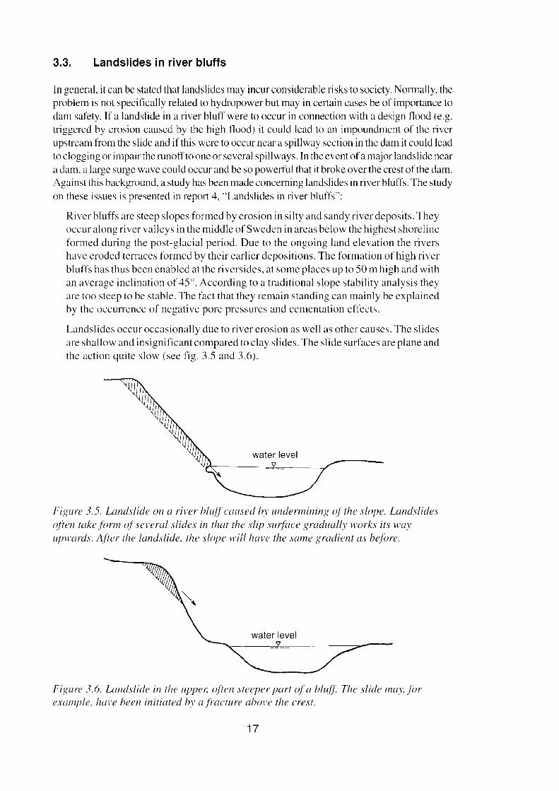
Landslides occur occasionally due to river erosion as weIl as other causes. The slidesare shallow and insignificant compared to clay slides. The slide surfaccs are plane andthe action quite slow (see fig. 3.5 and 3.6).
water level'V
Figure 3.5. Landslide on a river btuffcaused by undermining ojthe slope. Landslideso/ten takeform ofseveral slides in that the slip surface graduallv works its wayupwards. A/ter the landslide. the slope will have the same gradient as bejore.
water level'V
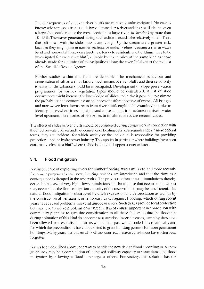
Figure 3.6. Landslida in the upper; o/ten steeper part of« bluff. The slide may.forexample, have been initiated by ajracture above the erest.
17
The conscqucnccs of xlides in river bluffs are relativelv uninvestigated, No case isknown where masses from a slidc have dammed up a river and it is not likely that evena large slide could reduce the cross-section in a large river (in Sweden) by more thanIO-IS'ir. The wavcs gcncratcd during such a slide are said to be relatively small. Trcesthat fall down with the slide masses and caught by the stream are a grenter risk.bccause they might jarn in narrow seetioris or under bridges. eausing a rise in waterIevel and horizontal forccs on structures. Risks to residents and buildings have to beinvestigated for each river bluff. suitably by invcntories of the same kind as thosealrcady made for a nurnber of municipallties aJong the river Dalälven at the rcquestof the Swedish Resene Agency.
Furthcr studies within this field are desirable. The mechanical behaviour andcementation of silt as weil as failure rncchanisms of ri ver bluffs and their sensitivityto externa] disturbance should be investigated. Development of slope preservationprogrammcs for various vegetation types should be considered. A list of slideoccurrences might increase the knowlcdgc of slides and make it possible to estimatethe prohability and economic consequences of different course ofcvents. All bridgesand narrow seetioris downstrcam from river bluffs oughtto be examined in order toidentify places where trees might jam and cause darnagc to structures or a rise in waterIevel upstrcaru. luventories of risk zones in inhabited areas are recornrncndcd.
The effects of slides in river bluffs should be considered during design work in connection with
the cffcct on watercourses and the occurrence offloating debris. As regards xlides in rnore generalterms, they are incidents for which society or the individual is responsiblc for providingprotection - not the hydropower industry.This applies in particular where buildings have been
constructed close to a bluff where a slide is bound to happen sooner or later.
3.4. Flood mitigation
A conscquence of exploiting rivers for lumber floating, water milis etc. and more recentlyfor power purposes is that new, limiting reaches are introduced and that the flow as aconsequence is damped in the reservoirs. The prcvious, oftcn annual, inundations therebycease. In the case of very high flows inundations similar to those that occurrcd in the pastmay oeeur since the tlood mitigation capacity of the reservoir then may be insufficient. Thenatural flood mitigation is obstructed by ditch excavation and deforcstation as weil as bythe construction of permanent or ternporary dykes against flooding, which during recentyears have eaused problems in sevcral European rivers. Such dykes prov ide local proteetjonbut may lcad to worse problems downstream. It is of course important in connection withcommunity planning to give duc consideration to all these Iactors so that the floodingsduring a situation of this kind do not come as a surprisc. In certain cases, camping sites havebeen allowed to bc cstablished in areas which in the past were flooded almost annually andfor which the preconditions have not cxistcd to grant building permits for more permanent
buildings. Many years later. when a flood has occurred, these circurnstances have orten beenforgotten.
As has been described above. one way to handle the new design flood according to the newguidefines may be a combination of increased spillway capacity at some dams and tloodmitigation by allowing a flood surcharge at others, For society. this solution has the
18
....._.,......."., """"h ~"I ..... 'o_......... ~"".. I1o"" _ ,r ,..' ,1"0:
....Il~.n '4'&'''1 ~ ~
n....""', p_hol 1l.'......_n""" ...~.·_ ~".. I1o.oI........... I"'"...d,........ ~ ~ _' 'D S~N; .1oD.-
n..~ ~"" p~........, n..>I~.a.._,._...l-.~ Io.,.... .-.I_.S._. n.. •• '....··_01....."..," • ....,.,f-tpn ~~...... ~__.._,'....."J•• ,eI.. ,_,..........
"""--"'"---'~--~._' ._--..._.."..... ll.o.ol_....,..._.... ....- _... .-........ .- __ .OS 1"0: -"" ""' _ _
•• dmd "" 110 --... """ "'_oII! .. _.-.. .--1<> ~.. ,..... _ ..1"'",,__ --.~..,-""' 0p0.T__• f'_.. ...-..1"'--_ ....-.__ ...• , ' ...1 n..""' ............._""""'_"'>dw"' "t-.._.......... _ ..... --. ..~_ .. I"o: '" ....-- _ ..
f,...... 1 \' ~ 'I"i"''''_lo.- '''''''- .. _ .....""_~._..._ • .,.... 1>'>..-.
.... r ..............~""- "' .., .... oI _ •• _ ..
'__",'" ' __.."..-,.,. >1.,-. """..-_ ....,.-........ ,., ...... "'1 _ "'-~• ..-_r-..._ __~~ d...,.._ p ___ _ ••, lk><Id<'e•• , """."... ,"' _- ..
Th< , ,00 1' ,,~, "ri~,"", lIy "",fId«j ,,,,I, k' .1",,1 .. ,!Il . « ;1< II<~>.I m'''f'"'''''. bo' .. "'''"'''''I""n' 11 ",,,,00..,,) lo' """ " ""~.",,n '" ~,,,,,,.I - "" n.,.".. ", >.I r"" " '"
1\ ri, l ,""cm",)' (~ ,h;, ',I'" ""')'~.';I)· , ;1< . .., .." ., impt<''''''' I'" ..'""ht'I«'"""",.....~ " I.,~, 1'",,, l>k W h., ,~)""~;loN< ri", ;n 0«1<, I."" kl ...1""," '11< 01{'.",,,.I<,,l>k ...-"1''''' h., h<,," n ..... ,n ,h;, ''''''"''. " n~'h .1<.., "'. ""'00, """...,"". t,,",
,l1<", ar< .. ' ""',, ,i,. ~It,..m, ,,, l1< ,'"n,;o",'" "',1"1 ~"..,"''''' ' "'I'''''"' ,h<
''''''I'' ""',,"'
" h<n" , .,.o"" ,,, ,..., ".1""""" ' 0 " ..,' MI""I" , l ",h"","" .,1,,"h<""""I """"..nb."n"," "f" ,""" ,.. h< m..Jo lO ~,II<",", "'Y'. ,,, "".ud< ,h< "',on,"" ,,,.,, mal on'"'""".Y.... .-oJ"""," "t 'h" l"..n." '"'"''' ,,,.,,,", ....,,1'''' .... ".""... <,·,1""""", .."cn 1'"""" , I"" "" ".,,,,,,,..s...,.,, 'n II", "uJ}' ho" t>«n ''''on th< I•• n, oj ,II<...-"""''''''''' '"'" ,'",,,,_ ne«",,,l' ,n,.<1<, .-.. 11..>.1 m"'f""'" ,>I' .." O,,, 'Yl""''" h< ,·,..."oJe",,) ",h , t.."")' 1'"."t"" ...t'.1~. f"- '"t oj 'k''''
., ",'."'"'1....... ,",h< "LoJ, ,h'" ,h<.l, tlicuilie, "~ ~',ot<J ""h "' ;1 . "'," m;Ii.,.,;',n '''"''h< ~,~".. oI.n !Il" '1r< "I .......·""'""l"""'" """,y """,IJ.,!.,.~, 1""'''''''' ho "',,;,loJ, oJ tn" "" rm....."'n~l.-d ,,·H.. n.. od rtliII ~.II,.... . ".,,"' oJ lIw, ""fui"-" ...,.:.to,k,"'"nn,,,,,... ".n'm''' ...... ",II", ""f"''''',,) '......-"""" ".J. ''I"'"'''J..oo ,·""""t "I,p;H",~ ~""<'" lo' "" cDri<d "W, 'I\n ..,h ' ho <"""" ""1""'<~ uf "'0"", ,"'",kl h< ..·0......Thi, """""'".. " '" . m Kdm.... " " " ,Ile "'".."' .,...." ,," . ~~ "'" 1"",""1",,,.1COOln",·,,,., "n I~", n.m, _ lem.D
t,.,.", j .H tJI< <~.'I_"' ...,' ~' IIh" ""; ,10< ,.""";_, I>u'li <'I"...,". "","II"." '" ,h,"'''1n<rtI ""''''''''",'''"" 1'''' p/><*' '."" ,' " " _ ..~"" ",'". 1;....,.~,
3.5. Flood mitigation during the compliance stage
During the period up until when the dams have been entirely adapted to the new guidelines,it may however, be necessary (and suitable) to use a flood mitigation approach if a flow wereto occur which is greater than the installations are currently designed to withstand. It istherefore important to have sufficient knowledge of each river in order to be able to judgethe possibi lities of mitigating the t100d during a period of this type. The legal conditions anddivision of responsibility for such flood mitigation measures should also have beenclarified.
There may also be good reason when the design work is carried out on the river to analysesituations that may arise if the turbine water tlow in a station does not stop (i.e. the station doesnot trip) at the same time as the stations further downstream have been tripped. This case meansthat a higher flow than expected will continue to the next dam. There isof course the opportunityto shut off the turbine water flow or not fully open a spillway, but this should in such case beplanned and agreed, especially if the rate at which the water level is rising is high. Preparednessfor such actions could be especially important during the compliance stage.
3.6. Dam break and impact calculations
The process of adapting to the Committee's guidelines is one reason for studying theconsequences of a dam break. The consequence classification for a dam is based on themarginal impacts of a dam break, i.e. dam age over and above the damage, which theextremely high flood eauses in itself. In some cases this may be easy to judge, but in manycases a more accurate calculation may be necessary ofwhat the consequences would be bothwith and with out a dam break in connection with successively increasing flow, In thiscontext it is a question of calculating how the body of the dam is successively eroded in aninitial stage and the flow thereby increases, and partIy how the water masses continuedownstream along the river. The study on these issues is presented in report IS, "Methodsfor dam break and impact calculations",
3.6.1. Dam break sequence
The question of how adam break is developed varies, of course, from case to case, but thereare often a number of common characteristics. If an embankment dam begins to beovertopped, this often takes place along a certain limited section of the dam whereby thedam starts to be eroded in this section so that the depth increases and erosion of the sidestakes place. The knowledge available conceming dam breaks that have occurred inembankment dams indicates that the dam break is developed relatively rapidly downtowards the faundatian level of the dam and willlaterspread mare slowly to the sides. Adambreak is often developed with surprisingly steep sides and even though major variationsexist depending on the size of the reservair etc., in the final stage the width of the openingat the toe is often one to two times the height. A study on this subject was presented atHydroPower '97 in Trondheim [9].
As regards the actual sequence of the dam break, i.e. how the opening widens in the verticaland horizontal axes with time, several established camputer programs are available, for
21
exarnple BREACH. A careful calculation of this development may sornctimcs be ncccssary,for exarnple, for objeets at risk in the vieinity of the dam. It is deemed possible to dcvclopa more physically correet description of the dcvcloprncnt time. sizc and form ofa dam break.Acareful evaluation of the program would be of interest. However, these questions have notbeen studied in any greaterdetail within the framework of this report series. Continued workis planned to be earried out jointly by the Swedish hydropower industry via El fors k AB.
3.6.2. Flood wave calculations
When it comes to the impaet of a partieular dam break. in the past investigations of anadvaneed and less advaneed nature have been performed for a number of dams. However,the potential for advaneed calculations has rapidly improved with time as a result. amongother things. of advances in computer teehnology. The consequences of extreme floods ina river valley have in the past not normally been studied. One of the activitics of this reportseries has been to look at existing methods to ealeulate how the water rcleascd by adambreak will propagate down by the river valley and also to analyse the eonsequencesalong a river in whieh the extreme runoff is assumed to flow unmitigated past the dams.
In general, it can be stated that for reservoirs with a large area and volume. the developmenttime for a dam break is of little importanee to the flood wave. On the other hand. the sizeof the fai lure opening is of great importancc. In the ease of high dams with small reservoirs,as regards both area and volumc, the development time of the dam failure is of greatimportanee. The importance of the various dam break parameters decreases. however, withincreasing distance from the dam.
3.6.3. Impact calculations
When analysing the impact of a dam break, the break sequenee and the hydrograph, whiehis a conscquence of the dam break sequcncc are used as input values for the continuedealculation of how the flood wave will propagate down the river. When calculating theimpact. a physieally eorreet mathematical model is needed in order to deseribe the unstcadyflow eondition in a dam break wave. A study has been made on this subject, whieh ispreserned in report 18. "Methods for dam break calculations":
A limiting faetor for accuracy when ealculating the impact of a dam failure is thetopographie maps available, usually with a S m eon tour interval. The accuraey couldbe improved by a systematic collection of calibration data during high floods and byimproved and more accurate maps with a Im contour interval in narrow river reaches,Improving maps along a whole river is prohibitively expensive. Mainly onedimensional mathematical models for t100d wave calculations are used..for exarnplcDAMBRK and Mike II. Two-dimensional dam break models or hydraulic modelstudies could be useful in very restricted areas. for example downstream from a damand where detailed and aceurate results are necdcd.
The mathernatical models utilising dynamic routing methods used today all suffermore or less from stability problems when ealculating flow conditlons near criticalflow. The elimination of such problems would !cad to lower dam break calculationcosts in the future. A substantiai part of the total cost of dam break calculations
22
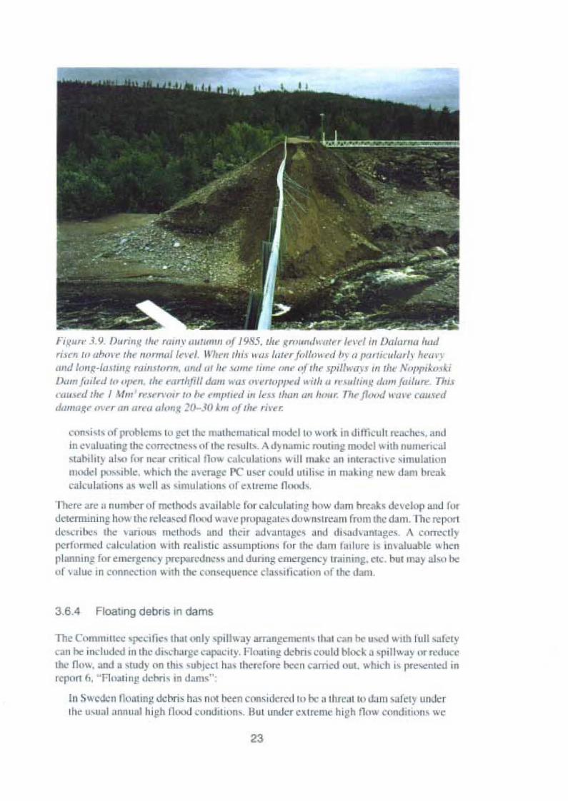
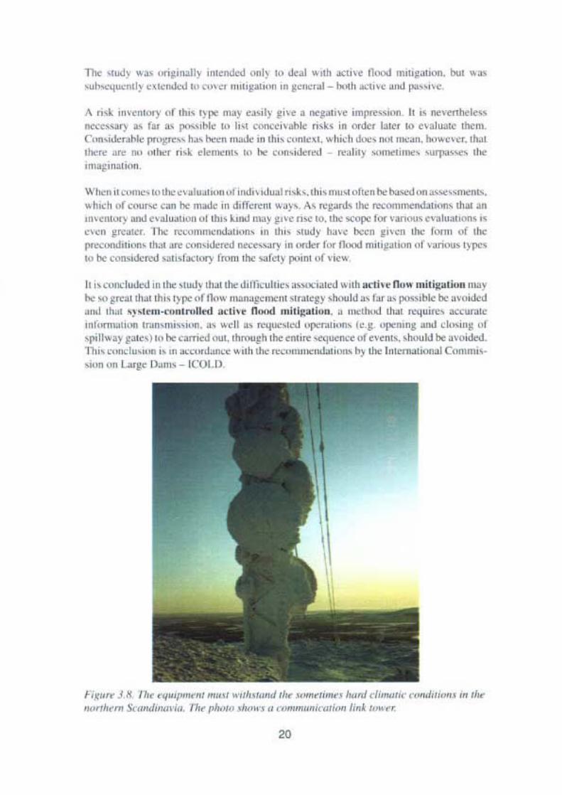
n g ll r r 3. 9. J)lI rill ~ th« ra tn v d1II /11 /1J 0 1 1985, II,,' , 'm urrd ,·:., / r II" I il , Dalurnu 1....1ris..., r" ,,1'111 'r l ir normal levet. II'lrcrr /ili, II u" 11111'" "1/,,,,', '( I>y o 1'<lIlintlw " 1,,'1/1'\'"'Id 1"" 1:-111.11111,1: ruins torm. nr rf '" I". .\(111/" tim, /lir;' I ~r thr ~I' ,/II1·I1,\.f /1/111" """I't ,i/W.l j
Dcun f ,"l f el t" ope«. th, <'ilnl"m "<1111 II',,, 11" "'/"1'/" '01 with o' ' lllt"l,~' ,11/1/1 {tu11m' TI u,'1111.1('11 th 1 .\//11 ' rrsrrvorrm b "fIIt""'" II' less thun , 1/1 honr: / , fl""" u 0 1', ' IUW,'eI
damag» l " er 1111 1I /'t /I /11" ",, 10-3IJ Åm "f til riv« r.
"o",i '1\ nf (l lem.. lo ~CI the matbc ma tica l nu I 1111 Wlln.. in dittlc uli teach ".llIdiII evulu ung the corrccmcw " 1the revultv. A J nanu mut mg II .) w ilh nu rue rical. lahi ht ~ .11" , fur n nr criu ".,1Ilow calculauon- wrll make ;111 mrcn...1I\·C imulati II
model I' 1 vihle, which thc : ve •p re u. er cuuld utili: i II ma ing n \\ dam l'c;\lcatculation-, ,I' weil", -imulation. "revueme n.."d .
'Fh ere an: " numb... r " I mcrh s available tor calcularing' how dam hrcak s JCI'el"p "HJ fil,dcrernuning how the relca-cd OIlOJ wuve plllp.l!!al" , dnwnvtr xrm from the dam. The reportdc -.:rihc - the vanou, 11l ' l hl1d~ anJ Iheir adv.nu ge - .111 J Ili'4ld\ anlage, . ,\ currect lypcrfbrmed calcu lation with realistic assumptiou , fur Ih., dam farture i invalua le whenI lunnms for elllergell"Y pn:parcdn. " and JUllIIg cllIergcncy training. etc, but fIlJ) ab" be:,l v.iluc 111 onnccuon wuh the nsequence I,,,,i licalinn ,' the dam,
3.6. 10811ng debns In dams
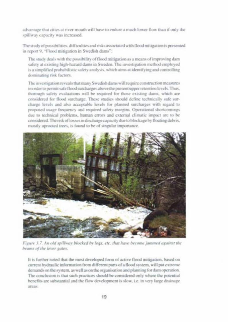
The Comnuuec ' JlC nf that only ' pilll\o1)' lIfr.ln~ m,'III' th.r t can u ·J with Iul l safi I .C.1I1 be includcd in the dl,ch.u ' l-.lp.leil ~' . Flual ing el .bri could block 01 'f illway ur redu -cthe now. und a tudy "n Ihis -ubjc ct ha., the re in ,... been arrled I1UI. whic h i, prese nred inreport fl , " Flo.uin ' .I·hö, In ;lIl1S"
III Sweden nuatin!:dcbris ha, ni I been w n,il lcrctl lO hl:a thrc.n In dam : akl) underrhe uvunlnnnunl hiph l100J 'llnJ ilinn" BUI under extrem high nu, comlition w,
23
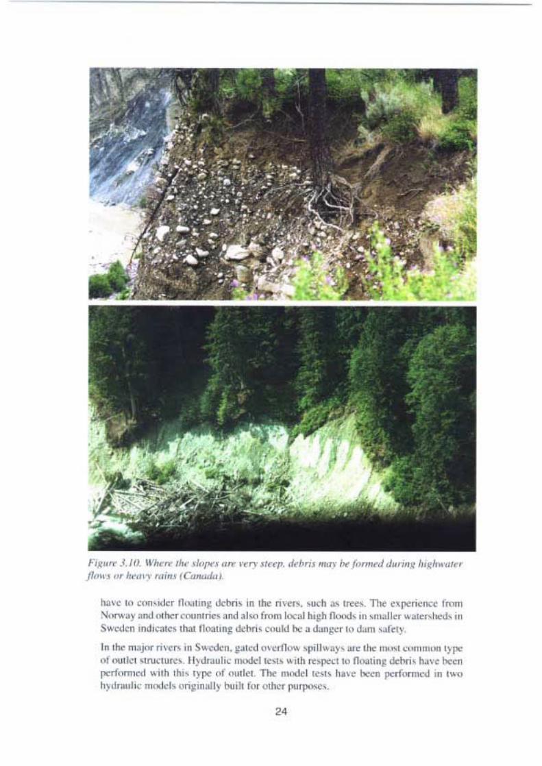
F.~.". .l . ltI. ".~,,,. Ih. "U'I'" "'" ,~n' .""r.Jt~n.< ...n "'.1"'-.1 d.,."~ ~,"~•."",fl,,,, ,,' """,. ,.Ii•.• ,('"",oJ.,.
""" tu ".",,-,<, Il," 'n~.J<l>n' in "'" nm " ""'h ~, '1'«,. TO< "1"'-;'''';< In'ffi" ''''''Y .od " "",,,,,,n,,,..,.oo . 1", In'ffi k .1 h,~h fh", '" ",..II", ~"",,,I""', '"~ w«lrn """""« th.. n""" n~ d""", , "....Id "" • d""~,, II' ""'" ,.f<'y
In,"" "" J"< m, ,, '" S" ,*" ~..,~ """/k,,, ' 1"11,,,,, ... ,I-.< n"'''' , ..", """' 'l P<nI .... ,,~ ."\.:, ,,« 1l,~,," I ", ",,01<1 .,," ,,"" ""1"'" n. n."';n~ d<hn, h..·< h«nf"' rt,,,,,,,,,, "'''h '"" 'Yl'< '~ "",..... Th< """"I ",.. Ju .. """" 1"'11',"""'; 'n ,,,n"~·d"...",· "'....·1. on~,".II ;- ~ ," ,,. "''''.. P"fl'O""',
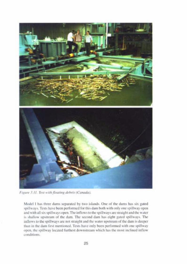
/, ..... .. 1I 1.... "'fI<""...-..'n........
\t. ""11~ Ih= "l'Of_~' ,..""L-lo. On• •O"" <lom. lIP ~'._'1"'1...) ,. T... , t.xI1 ('<"f,,,,,,,,J I,.... ".tom ..oh .. "h ,..I, ·,_ 'I"""'~ "I,.n....1.. uh . 11" . , ,,,II ,, "I'" n.T!><olnl]".. , l.. 110< '1"11.. , ,, .... '''.,~h, .".j, l ''' .. >I'T" -1>.11 1 "f"I"""" ,. Ih< ""'" 111< "",.,.j 14m t." ,;~hl pl«I .... " .. , ,, Tb<1lIJ1<o.. , lh< ""1I...y',,, ... " r..~1M _,1>1 III< ....... 'f"I",.m ,,(,hr <lom" <l«P.TI..... In ,"'.l.m !;'" __-.I. r , ,,' ""I, lun ""n ~ ,_ ""II ,•.,..... ,h< '1"11"'" 100.-..... r .10 «_ ..ho<h '"', , "" ,..,h"'" .n,...,-,-,,-
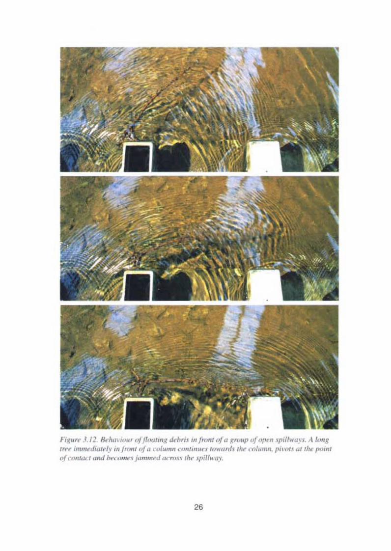
Fi.~"" · .I. /2. H. /ra 1"11' III j1"al/ll~ dchrts /Il [nmtoj« groI II' "f "/'1'11 '1"//\\'1/1-'. A /,'"g",. illllll ,·,jillll'l.l' III 1"111111 II t't'/II11111 continu .\ Im. mr! Ih t' cohnnn, 1'"'"'' at th point
,~, ront,« t .111.1brromr» [unnnrd lJCnll .\ ihr J/JUlu'lY.
26
\l ud '11111,,, '" 'C:"I,,.I 'pi llway. lh c mll"'l tu Il " piliw,IY 1< ' llalghl.lIld ch ,,~. rdecper COIllI';HTlIlO Ih nther dam
• m,,1I pme an I pru e pl'lllb \\ ere u cd u 111' ''' -I tree-. The r" "l diameter i .l III Ihru ( lhe tree s' lcngth••l mca -ure Iound In rh ~ur\ cgl.l ll ' lu,lr. Pm ' , I spru e .IIC theIl1{lSI conunom r -e in Swed 'Il. T., dcxcril 'I I I I" w condit ionv .md the k ll)!l h " f lh,'trec 111 re luuo n lu rh" ' plllwa} IIlc di men-aonlcs« param le'" HIB amJUB r ' u, 'd.
Ine results f", 1TI 1II,' m..J~II':' I' II~\" incrc , d the undervrandi n Il Ih I h.J' iuu r01 Iloal 111 " dchn - : nd poin tcd out impon .un fol II If' tor all llW in~ debn lo 1'.1' th roucha 'I illwil} openmg 111 a d;ulI.The Il' I ' sho w Iha l onc such 'pill",:!) u, ually \\ ill nllowI '111"1e trec lu p.", with iIlcllgth 1\1 ice the width ur Ihc gale - Ihe rrcc will turn 10I c
d irecuon ur the nu",. nd Jl'l" the vpillw I) wuhour allY I' Ihlc:m . \Vh 'Il I\\1I tlc e,emungled wuh Ilnl· .1I1 Iber 011'1''''.1' h tbc 'lime [lill\l'i1Y' urening th -, d 'n"l 1';1' ' uca'l ly. One trce can rum 111 the dUl',:liu ll n r the 11.,\\ 1l<J1'1Il , I count o lthc ther trcet'octll)! turned ", fl '" till' piIlJr, , ( he mudcl I" .salso , h.." 'd l .uwith ma Il)' -pil lwuy«IIl' ,'1 tu cuc h other, the wuter 11m. would nLOI Ium t ik" ing l trce ~hnl' Ihe n'l\\d rrccu 11 a, wel l .• with only one ' pill",,) (, 'C Ii ' . 3.1~ t. The 1."1' ,11"HCH'.alc" l cimportnuce (,r a ~""J -prllway d srsn: III II <1<:1.ul. can unpruvc the ' ''1'.1 Hy 101II..uunu d ' t'!riv.
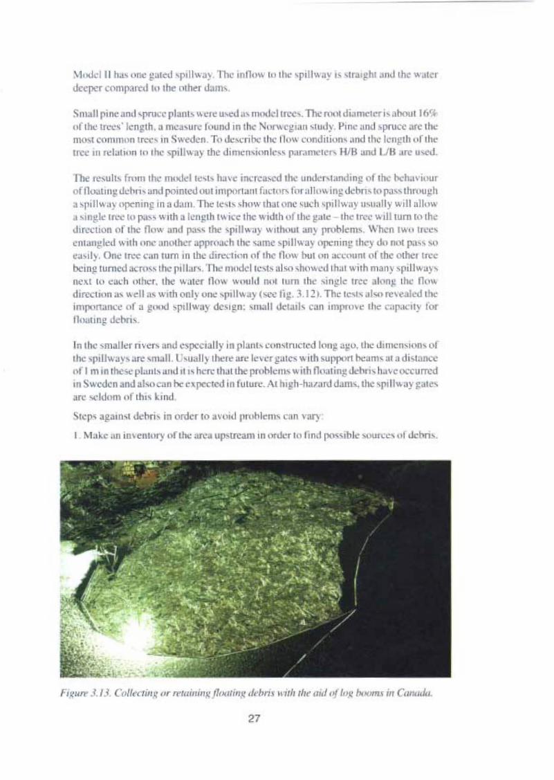
In the milller n ver» und espccially in pluru con-am red '"ng auo. the dimension«ofrh ' , pillway an: vrnall, lI aII ) Ihel e are h~\ er g ucs \\ uh upport bea mvar istance,'I I m III thcsc planl' i1Il" 'I I' h re th.n tlk- pr< hlcmv with Ou I t i n~ h", havc occ urredIII wcdcn and al. " an be C\J1<:Cled iIItuturc.A t h lg h· h;o ~.mj dalll, .thc ' 1'111\\ay g, 1(',are ..cld om I' f lin, \.. 111<1
SI ' ps aj!3l1lsl dchri-, in order to a\ """ "" ,1,,111, c III vnry
I "'t"k rn inH' l\Im y of the n:;l up tri: 1I\ m order hl 1111 I lXl' .1.11", ourccv••1<khn' .
27
~ . AIII.UI .,gcmcnl p l .:m f"'l hc lln·.II , o~ l ~mnnco \\ hcrc c .g UI.""' . lu ghe r than l ~I IIllCS
the spillw I ~ ul nIII!! are uikcn J u" Il . cr ovio n pn uec n n is perfo nned C"
·1. New ' pili",.I)" " ith all in iproved UCSIj; 1l in oul cr t« mini mrsc lhe ri s for l hn , lam.
5. J'll'parall"n" f r clearing III ' 1'11I" a~ s trum dcbru J n" h) using ma hmcs,hluslinf erc
fl , lmpr.. \ the uC' i)! n [f nid I' l lI wa~ s In " ":TC "'" the probabrliry lir tmublc-fre
p.""ali'· " ' dcbris.
A eo mbiru tionof lhe~ slCp' cou ld be the be -t s.. lut ion. One mu t look 1I1''' lI lhe whnlriver ' y. i crn and be uware Ihal solution uf dehri -, pn,llkms d l lI lIC dam m.IY t<X'1a dum downstrcam,
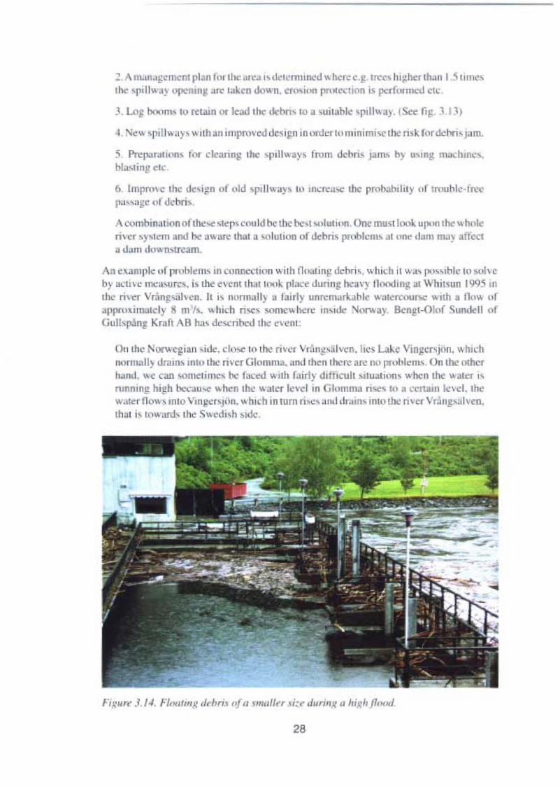
An example nr pn blem, III cnnn .ction with 1l" "ling dehriv, which il "',,, p",s.bk to solvcb)' active I1IC; sures . is the c\ ent tha t ro« . pl:I C during hc;,\')' rloodrn I " I Whitsun 1995 111lhc river Vrångsalven. II i, nnnnall) a tair! un rerna .ahl wute rcourse Wil l! 3 tl U11 liruJlpn1\imalcly m {s. \\ hi 'h n -.c, somc wherv m,,,I , o rway. Bengt-Olof unde ll ojGull» n!! Kraft AB h.l' desertbed II • evem:
On the Nllrwegian ,iue . d n", IUIhe river Vr:lI1g.s~ l\cn , III'S Like Vjllj:cr,jtlll. \\ hichno rm II ) dra rus min the rive r Glomma, and thcn rhc rc ar... nu 111>1 ICIlI' . Un the otherhand, \\ can vom lim' be tuced wuh f..irly d l t icult _uuauons wh n the ater rrunn ing hieh becau-e whe n the wa tcr lcvcl in JI ' fll m ri s III Il cruun level. the\I ater (h", s into Vi"!!C" (;11. w hich IJlIUII1 ri, c , :11 111 dr" ins i1I111 the ri \ er Vr:lngsnl\ en.[h~ 1 is IOwal\h the Swedish ' Ide .
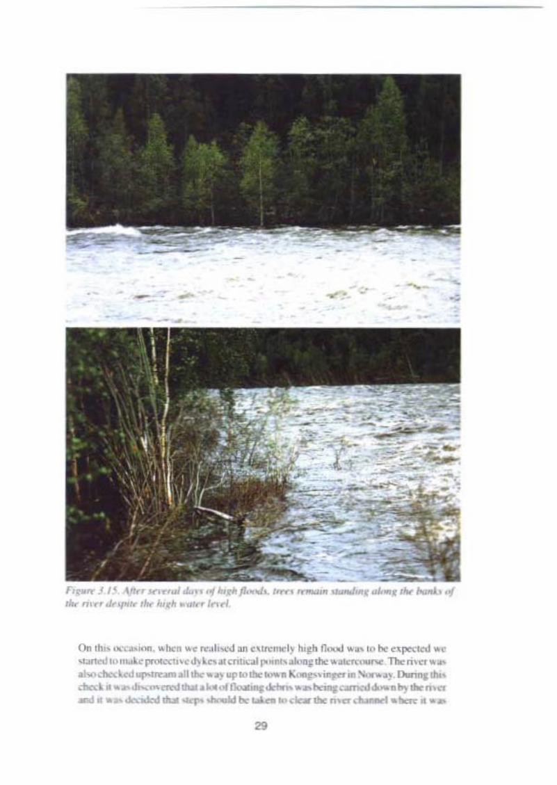
Figur« 3.1-1. n ,I(J/",g drbri.• ,~ " maller hr ,1ur"'.1: " 1ti,1:/rP'HJt1
28
---- -.-- .,
',..... .." ,__.0/..,.."'........... ..- -.... ......""_.0/Ho. ..,•••.,.." ~.....-"I<'orl
0" 'lo. ,~,- ,.. ..,,, Io J " ",..rl~ ""h 1Io~" ,O' "" ..p" ._., <~,,<""~ ~ p.""..,""' ,_ T1l< m ..
01."_",,,,_.._011 ""' "" .,,,,,,_" "''"'"' ~_ 0..,. .....doa:~ _ ....__.~.,.-..._ <>m«l "~ ...n ....._ "" _ ... <1 ..-._._•••
"

becoming clogged by trees and other debris that was being swept downstream.Particularly sensitive objects were spillways, bridges and other structures on and inthe river. In order to aequire tlcxibility and capacity in this work, a mobile crane witha grab claw was Ieased and put to work. The results were good and it proved to be arational way of keeping spillways and other eritiea! passages clear. The clearingoperations were probably decisive in being able to cope with and master the powerfulIlow, whieh at its peak was running at 80 mvs.
There are also examples of how large trees and islands of floating pcat have been removcdby boat or helicopter in heavy flooding situations.
The report describes the problem of floating debris and a number of possible solutions. Itstates that in norrnally high flood conditlons (with a return time of 40 or 50 years) floatingdebris has not poscd a safcty problem for dams ofConsequence Class I or II, bur at the sametime it is ernphasised that the spillways must funetion as planned even at higher tloods (froma 50 year return time up to the design flood as per the Commiuee 's guidelines) without beingblocked by tloating debris. It should be noted that even if the questions related to tloatingdebris are very important for Consequenee Class 1 dams aeeording to the Committeesdefinition, they should also be considered for Consequenee Class II dams, partly beeausethe safety of these dams shall be able to withstand a lOO-year tlood and partly because thecollapse of a Class II dam eould lead to the eoneentrated release of a large quaritity oftloating debris which can often constitute an additional risk to downstrearn dams. The reportalso recommends eontinued development work within the area.
Questions relatcd to floating debris are important and should be given special considerationin the continued work involved in adapting dams to the Comrnittee's guidelines and in thework on common guidelines for dam safety. Inventories should also be made of sourees offloating debris.
30
4. INVESTIGATIONS CONCERNING EMBANKMENT DAMS
4.1. General
River dimensioning is usually based on existing data concerning the power stations orregulation dams. and includes information on the level ofthe impervious core and dischargecapacities of the spill ways. It is. of coursc, very important for this information to be corrcctand that the dams mcct the rcquircments for dimensioning in other respects, Checks mustthcrcforc be carried out by carefully analysing each dam. This checking should also coverthe dam Ioundations. fl should be carried out before the selected solution is finallydetermined since it would otherwise be possible at a later stage, once the mcasurcs havebeen earried out, to find that the preconditions are not met and that the solution adoptedcannot be implemented or can only be implemented at a significantly higher cost. Inaddition. sensitivity analyses should be performed so that information is availablc on whattactors have a particularly strong impact on the course of events.
Checks of the kind outlined above should be made not on ly in connection with the newdesign flood but also concerning dam safcty requirernents in general. This applies inparticular. of coursc, 10 cmbankment dams of Consequence Class I but also to dams ofConscquence Class II.
A review is given below of factors that should be given particular attcntion.
4.2. Flood surcharge capacity of embankment dams
In those cases where the discharge capacity at the retention water level is lower than thedesign flood, the Committee 's guidelines permit that tcmporary f100d surcharge. i.e. fillingto a water level higher than the prescribed retention water level, may be employed inextreme cases in order to prevent dam failures in downstream dams. However, such f100dsurcharge may not be carried out so that the safety ofthc operator 's own dam is jeopardised.A survey has been carried out to clarify under which conditions a f100d surcharge may beemployed. The study is presented in report 15, "Flood surcharge capacity of embankmentdams":
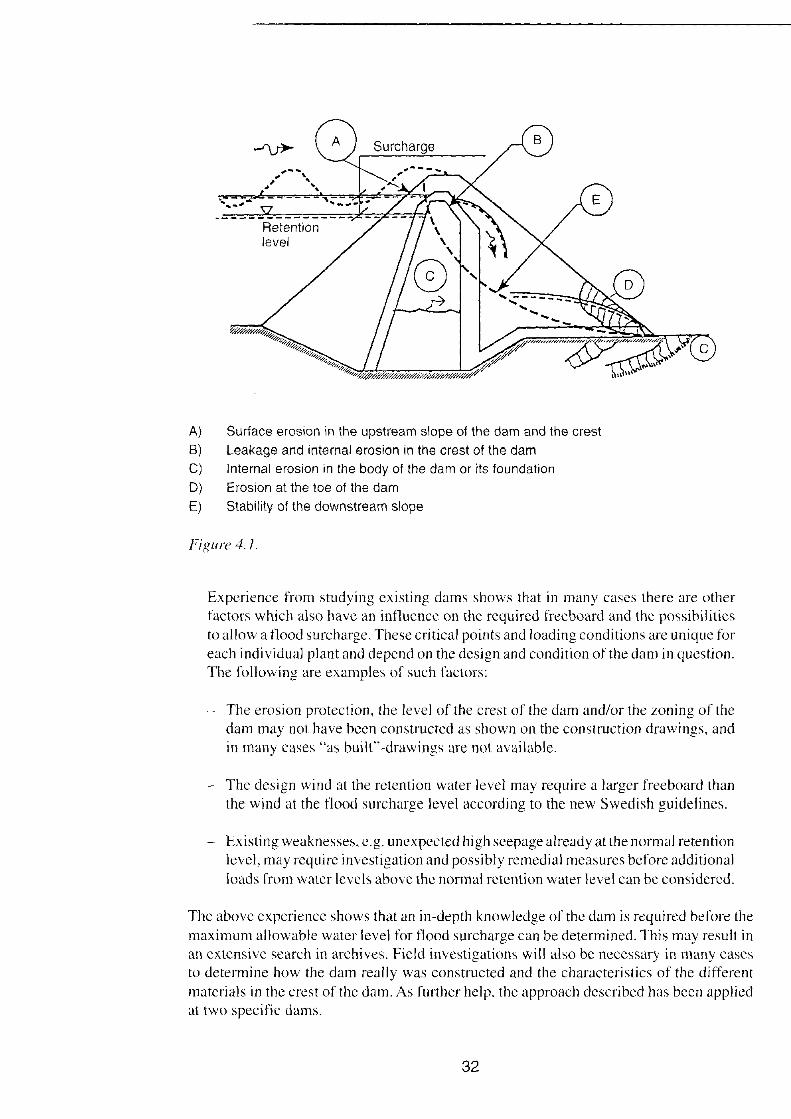
The following critical points, common to most of the plants, may determine themaximum allowablc water leve! (see fig. 4.1 ):
- The effect of waves.~ Intemal erosion in thc body of the dam or the foundation.- Seepagc/leakage and erosion in the crest of the dam.- Erosion at the toe of the dam.
The stability of the downstream slope.
The report deals with each of the above points in turn. Exarnples regarding estirnations of erosion rcsistance at the dam toe are also presentcd. Finally, the rep ortpresents examples of reinforcement measures, which may be necessary in order tosecure the dam for a flood surcharge - a water leve! above the normal retention level.
31
Retentionlevel
Sureharge
A) Surfaee erosion in the upstream slope of the dam and the crest
B) Leakage and internai erosion in the erest of the dame) Internai erosion in the body of the dam or its faundatianD) Erosion at the toe of the dam
E) Stability of the downstream slope
Figl/re 4.1.
Expcrience from studying existing dams shows that in many cases there are otherfaetors whieh also have an influence on the required freeboard and the possibilitiesto allow a f100d sureharge. These critical points and loading conditions are unique foreach indi viduaJ plant and depend on the design and condition of the dam in question.The following are examples of sueh faetors:
The erosion protection, the level of the erest of the dam and/or the zoning of thedam may not have been eonstrueted as shown on the construetion drawings, andin many cases "as builf'-drawings are not available.
- The design wind at the retention water level may require alarger freeboard thanthe wind at the t100d surcharge level according to the new Swedish guidefines.
- Existing weaknesses, e.g. unexpeeted high seepage already at the normal retentionlevel, may require investigation and possibly remediaI measures before additionalloads from water levels above the normal retention water level can be considered.
The above experience shows that an in-depth knowledge of the dam is required before themaximum allowable water level for t100d surcharge can be determined. This may result inan extensive seareh in arehives. Field investigations will also be necessary in many easesto determine how the dam really was eonstrueted and the charaeteristies of the differentmaterials in the crest of the dam. As further help, the approach described has been appliedat two specific dams.
32
4.3. The effect of waves
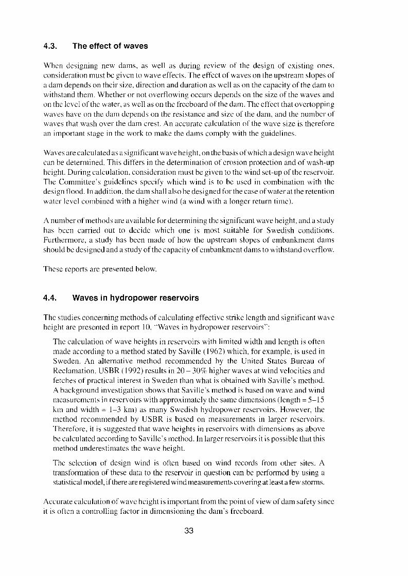
When designing new dams, as weil as during review of the design of existing ones,consideration must be given to wave effects. The effect ofwaves on the upstream slopes ofa dam depends on their size, direction and duration as weil as on the capacity of the dam towithstand them. Whether or not overtlowing occurs depends on the sizc of the waves andon the level of the water, as weil as on the freeboard of the dam. The effect that overtoppingwaves have on the dam depends on the resistance and size of the dam, and the number ofwaves that wash over the dam crest. An accurate calculation of the wave size is thereforean important stage in the work to make the dams comply with the guidelines.
Waves are calculated as a significant wave height, on the basis of which a design wave heightcan be detennined. This differs in the determination of erosion protection and of wash-upheight. During calculation, consideration must be given to the wind set-up of the reservoir.The Committee's guidelines spccify which wind is to be used in combination with thedesign flood. In addition, the dam shall also be designed for the case of water at the retentionwater level combined with a higher wind (a wind with a longer return time).
A number of methods are available for determining the significant wave height, and a studyhas been carried out to decide which one is most suitable for Swedish conditions.Furthermore, a study has been made of how the upstream slopes of embankment damsshould be designed and a study of the capacity of embankment dams to withstand overtlow.
Thcse reports are presented below.
4.4. Waves in hydropower reservoirs
The studies concerning methods of calculating effective strike length and significant waveheight are presented in report 10, "Waves in hydropower reservoirs":
The calculation of wave heights in reservoirs with limited width and length is oftenmade according to a method stated by SavilIe (1962) which, for exarnple, is used inSweden. An alternative method recommended by the United States Bureau ofReclamation, USBR (1992) results in 20 - 30% higher waves at wind velocities andfetehes of practical interest in Sweden than what is obtained with SaviIIe 's method.A background investigation shows that Savilles method is based on wave and windmeasurements in rcservoirs with approximately the same dimensions (length = 5-15km and width = 1-3 km) as many Swedish hydropower reservoirs. However, themethod recommended by USBR is based on measurernents in larger reservoirs.Therefore, it is suggested that wave heights in reservoirs with dimensions as abovebe calculated according to SavilIe 's method. In larger reservoirs it is possible that thismethod underestimates the wave height.
The selection of design wind is often based on wind records from other sites. Atransfonnation of these data to the reservoir in question can be perfonned by using astatistical model, ifthere are registered wind measurements covering at least a few storms,
Accurate calculation of wave height is important from the point of view of dam safety sinceit is orten a controlling factor in dimensioning the dam's freeboard.
33
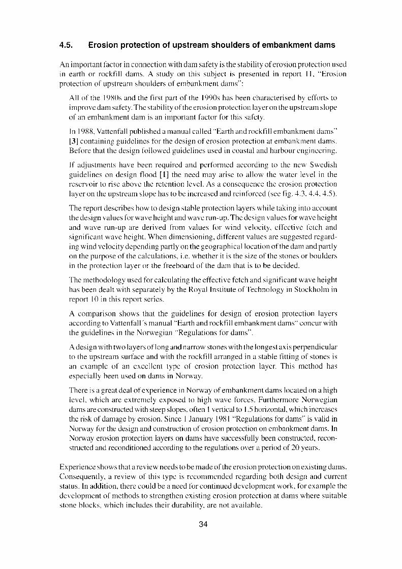
4.5. Erosion protection of upstream shoulders of embankment dams
An important factor in connection with dam safety is the stability of erosion protection usedin earth or rockfill dams. A study on this subject is presented in report II, "Erosionprotection of upstream shoulders of embankment dams":
All of the 19S0s and the first part of the 1990s has been characterised by efforts toimprove dam safety. The stability of the erosion protection layeron the upstream slopeof an embankment dam is an important factor for this safcty.
In 1988, Vattenfall published a manual called "Earth and rockfill embankment dams"[3] containing guidelines for the design of erosion protection at embankment dams.Before that the design followed guidelines used in coastal and harbour engineering.
If adjustrnents have been rcquired and performed according to the new Swedishguidelines on design flood [1] the need may arisc to allow the watcr level in thereservoir to rise above the retention level. As a consequence the erosion protectionlayer on the upstream slope has to be increased and reinforced (see fig. 4.3, 4.4, 4.5).
The report describes how to design stable protection layers while taking into accountthe design values forwave hcight and wave run-up. The design values for wave heightand wave run-up are derived from values for wind velocity, cffective fetch andsignificant wave height. When dimensioning, different values are suggested regarding wind velocity depcnding partly on the geographicallocation ofthe dam and partlyon the purpose of the calculations, i.e. whether it is the size of the stones or bouldersin the protection layer or the freeboard of the dam that is to be decided.
The methodology used for calculating the effectivc fctch and significant wave heighthas been dealt with separately by the Royal Institute of Technology in Stockholm inreport 10 in this report series.
A cornparison shows that the guidelines for design of erosion protection layersaccording to Vattenfall 's manual "Earth and rockfill embankment dams" concur withthe guidelines in the Norwegian "Regulations for dams".
A design with two layers oflong and narrow stones with the longest axis perpendicularto the upstream surface and with the rockfill arranged in a stable fitting of stones isan cxample of an excellent type of erosion protection layer. This method hasespecially been used on dams in Norway.
There is a great deal ofcxperience in Norway of embankment dams located on a highlcvcl, which are extremely exposed to high wave forces, Furthermore Norwegiandams are constructed with steep slopes, often I vertical to 1.5 honzontal. which increasesthe risk of damage by erosion. Since I January 1981 "Regulations for dams" is valid inNorway for the design and construction of erosion protection on embankment dams. InNorway erosion protection layers on dams have successfully been constructed, reconstructcd and reconditioned according to the regulations over a period of 20 years.
Experience shows that a review needs to be made of the erosion protection on existing dams.Consequently, a review of this type is recommended regarding both design and currentstatus. In addition, the re could be a need for continued development work, for example thedevelopment of methods to strengthen existing erosion protection at dams where suitablestone blocks. which includes their durability, are not available.
34
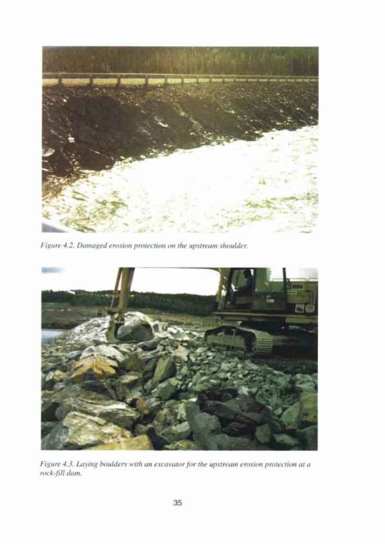
-.-~:-..-ij
" -, ,c
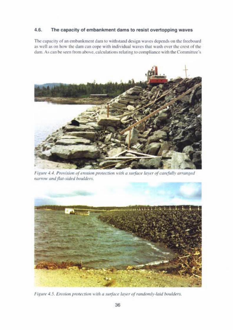
11>< <' p"' uyaf on<mM ,m,,"' ~'"" '" ....O!I~-.J "'.,.i~n "'''' "'Wn.l, "" u.,r~""' ,,<fl .. "" h".. ,'" d.\rn ""0 """" " 'uh ;r1di,·Hlu.oI "'V<' , <11 o"cr ,110: <I'<" '" ,I><~"n . '" ," 0 "" _" ' nom " • . <.""r kol Io~ ,o> " ompIi,n<' itfl '"" C ••,,,,,,,, ' .,
fi~." .. .. PR""'"'' of .a",,,,, pm,,,,,,,.. 0·,,10 " .'lo""''' I"""'1·"""'lolh ",,"",d'lam ..' ah<!fl"HiJ." "',./J",_

guidefines for dams of Conscquence Class I are carried out both with the water leve l at theretention water level and at possible Ilood surcharge leve!. In both cases, the level increaseswith a possiblc wind set-up of the reservoir water level. The study is presented in report 12,"The capacity of embankment dams to resist overtopping waves":
This stud y has been made in order to clarify what is required of the fil! in the crest andalso in the downstream slope and toe ofzoned earth fil! dams in order to resist erosionduc to overtopping waves. Consequently, the purpose of the study is also to give anindication of how the fil! material in the crest and shoulders affects the need forfrccboard.
A basis for the assessment ofnecessary minimum frceboard is obtained by calculatingthe water Ilow over the dam crest due to overtopping waves, the ability of the damcrest to resist wave erosion and also the stability of the downstream slope and toeagainst the pressure of overtopping waves.
A review of theoretical methods for the calculation of Ilow over the crest of earthfilldams due to overtopping waves shows that the unreliability of the results from suchcalculations is significant. The method that is proposed for such calculations isassumed to provide information about the magnitude of the Ilow. The tlow increasesrapidly with the size of the attacking waves. Therefore, the accuracy of the resultsdepends on correct estimations of the wave size.
The method mentioned in the report regarding stone design in dam crests in order toresist erosion by overtopping waves can be used for rough estimates. However, theresults of the calculations are unreliable.
If the dam shoulder fill is permeable, there wil! be agradual reduction of the surfaceIlow on the downstream slope ofthe dam due to overtopping waves. This should meanthat with the same fill material. the crest or the downstream toe will erode before thesurface material in the downstream shoulder. However, if the shoulder is made up ofmore fine-grained material, e.g. sand or sandy gravel, pore pressures may develop inthe downstream slope, which will result in insufficient stability with regard to slides.Repeated overtopping of the crest can therefore not be permitted if the shoulder fil!is constructed of such material.
If the shoulder fil I is permeable, the water which has Ilowed over and through the crestand core of a dam will be led into the fil! and then Ilow out at some low part of the damtoe, thus forming a water spring. Here, the Ilow rate depends on how the topographyof the terrain leads the water. A mathematical relation is proposed for the assessmentof necessary stone size in order to prevent erosion of the downstream toe.
With the purpose of demonstrating how much water can be conveyed due toovertopping waves, and the consequential demand for proper stone size, numericalexamples based on the characteristics of a typical zoned earth or rockfill dam areincluded in the report. The freeboard of the dam has been assumed to be 2.0 m and3.0 m, respectively. For the wave predictions an effective fetch of S km has beenassumed.
37
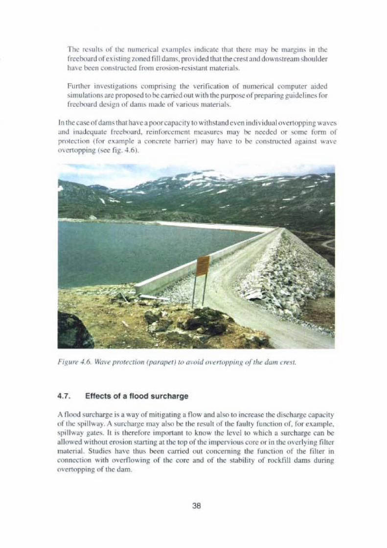
1 h' I ',u it "l the numencul ~ .lIl1pk, IIldlt:at~ Ih.ll thl.·l~ may be mar 'in' iII rheIrceboardIl ' e\iomllg 7 ned till dam . provide j th.u the C1 e~1 and Il< \Vl\~ I re; 1I11 shouklerh..w been con- tructed fmm ew,iun-rc:, i, 'anl rnatc rra!v.
Further invc sti 'ali(\I" ,"Illpri,in~ the verifi• •uion or numericnl cornpuier uidcdsirnularirm« are proposed 10 lIC carricd out with the purpose nf I'rep. ringguidclinl-'; forfrcchllalLJ de,ign ul ,b ill' lIlilde u l \'aIi ou, ma teriu l».
In 11 case nfdam: tluu have :'1 H,n':' 11,1 ity hl withsturnl evenindividuulovcnnpping W;I\ r-sand madequate fred'11;m!. ICmfllrt:c mcnl m u,un;, muy • nccdcd nr sorne form 01prorec tion l fnr exnmp le a "mCITt" ba rrler may han ' l " be consnuen-d ;\galll'l wavell\'cJlIIJlpinl,! 1,'1.'<:' ti l,: , -l ,Il ),
Figure -1,6, ~~I \ 't' r l'" r("I.' rioll (plll'tI{'(' fj /0 ta 'oh l 01 CI'1I 'l 'l,i llg "f lIre "<1111 crest.
4.7. Effects 01 a flood surcharge
A flood surcharge il. a way nf muigating now and lso 10 incrcasc the discharge ca paci tyof tbc xpillway. A surchnrge möt)' nlvo be tbc result of the l:Lully tunetlon IJ f, I f exnmple,'p ; lI w,,~' g;lIc,. Il i, therelnrc important 10 know the lcvcl lo which a surcharge can beallnwe I whhoiu erosion 't. rting at the rop of the irn pervious mc or in the ,, \ erl ~ in~ IiIlelmatertal. tudics have thus h-e n carricd out con ermng the funcrion oj the lille, In
connection ...uh overflowing nr ihe corc and of the ,Iabllily of rockfilt dams duringO\'t'rtnpping of the dam.
38
4.8. Erosion in the crest of the impervious core
The initial intention of this study was to describe the risks of erosion in the crest of theimpervious core if the water level were to rise so high that there was a tlow of water in thefilter above the corc (overllowing of the core). The study was subsequently extended toinclude a more general overview. analysis and review of established criteria for reliablefilter funetion with respect to broadly graded base material such as moraine for tlow paralIeIwith but also at right angles to the interface between base material and filter. The study ispresented in report 14, "Geornechanical filters and erosion in the crest of impervious core",
The report contains a selected review of theoretical and experimental investigationsin the field of granular or geomechanical filters and filtration phenomena. Part of thepurpose has been to distinguish between and prov ide appropriate design criteria fordifferent types of filter situations with regard to degree of stability, type of hydraulicload, gradation and effects of eohesion. Consequently, a distinction is made betweennow paralIeI and normal to the contact surface between the base (the erodible soil) andfilter material. cohesive and friction material. horizontal and vertical filter surfacesand geometrical and hydraulic filter criteria.
A geometrical filter criterion ensures that the base material is stable after an initial,small amount of volume loss irrespective of the hydraulie load applied on the filtercake. Sherard (1984) found that the equality Di/dR' = 9 corresponds to the geornetricalfilter criterion if the now is perpendieular to the base/filter interface. For cohesivebase soils, the critical grain size ratio can be as high as 60. On the other hand, if theflow is paralIei to the base/filter interface, erosion is not prevented to the same extentby rnechanical clogging. Hence, for friction materials the grain size ratio appears tobe somewhere in the range of 6 to 8.
For economical or practical reasons. hydraulic filter design may be utilised. Thismethod implies that the geometrical filter criterion is not satisfied and, as compensation for this simplification, the choice ofbase and filter material is related tothe designhydraulic load. Since the base material in such a case is subjected to a small but finiteerosion rate, the destabilising effect should be considered in the whole life span of thestructure. However, successive clogging of transported base grains. in variabledegree, leads to a decay in erosion with time which is a significant factor to thecapability of the hydraulic filter. Accordingly, the current investigation includeslaboratoryexperiments on filter development of widely graded base soils with tlowparalIeI to a honzontal interface. This problem is concurrent with the erosion processinduced by tlow over the moraine core in a rockfill dam and erosion in canal bottomsprovided with hydraulic filter material.
On the basis of a known grain size distribution curve for the base soil, the surface areaof the base soil that is exposed to tlow and available to erosion can be described asa function ofthe filter development and indirectly to the erosion depth in the base soil.The available area declines with continning erosion and thereby with continuing filterdevelopment. In the evaluation of the experimental results, the statistical relationshipbetween a dimensioniess parameter representing the transport rate, the available areaand another dimensionIess parameter representing the hydraulic load was determinedfrom multiple linear regression. Both dimensionless parameters were derived from
39
physical principles. The transport relationship is verified by the experimental resultswithin the ranges:
l.l l < d/()(/d'5< 4.43; O < X /d'5< 30; O < J < 40
and
The proposed rclationship can be used to describe the erosion process induced by waterovertopping the core in an earthtill dam as was done by Wörman & Skoglund (1992).
One conc!usion that can be drawn is that a filter can function even if the filter criteria arenot entirely rnet, but the fact cannot be ignored that material migration will take place in thelong term. Il should, however, be noted that the study prirnarily concerns tlows paralIeI tothe bas e material. During a high tlood situation, a short-term overtlowing of the core is morelikely to occur and the report indicates that in certain circumstances this may be accepted.
4.9. The stability of rockfiII dams during overflowing of the core
An investigation has been made of the behaviour of rockfill dams during increased leakageand during overtlowing of the core, the filter, the transitional layer or the rockfill. The studyis presented in report \7, "The stability of rockfill dams during overflowing of the core":
Rock-fill dams in Norway and Sweden are generally of similar design - a core ofmoraine, protected against erosion by surrounding sand filters downstream as weil asupstream. Outside the sand filter there is a transitional Iayer with somewhat coarsermaterials and then rockfill, usually consisting of stone without any special demandson assortment. In principle, each layer should function as a filter to the next layer,
A certain amount of water always seeps through the care. A sudden increase in thisseepage (without any connection to variations in the reservoir leveI) may be a sign ofan unstable core. If the seepage water is rnuddy it contains suspended material whichprobably originates from the core. This indicates a possible on-going materialtransportation from the core, which has to be carefully monitored by those responsiblefar the dam. In this situation, among others, it is very useful to know what seepage thedam can withstand from a stability point of view with regard to damage to the damtoe and in the rockfill downstream.
Another situation, of particular interest in connection with the reviewing of damsbrought about by the new Swedish guidelines on design flood, is when water tlowsover the care and into the downstream fill. Hypothetically, this can occur at very highflows, if the spillways are blocked or after a dam failure upstream. The reportdiscusses different scenarios due to water tlowing over the top of the care, the filter,the transitionaI layer or the rockfi Il , and also shows how calculations can beperformed. Furthermore, the report shows how to calculate the stability of the crest,the stones at the dam toe as weil as the rockfill and also to what level the water in thereservoir can rise before eausing a dam failure.
40
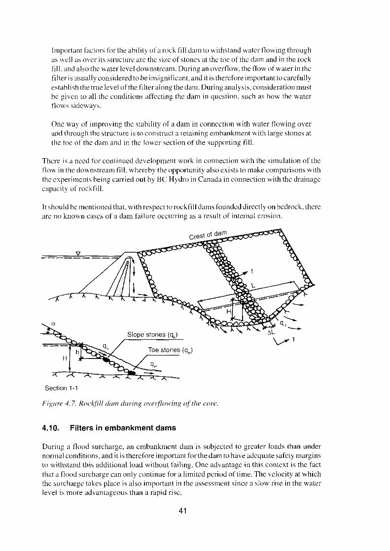
Slope stones (qh)
Toe stones (qH)
Irnportant factors for the ability of a rock fill dam to withstand water flowing throughas weil as over its structure are the size of stones at the toe of the dam and in the rockfill, and also the water level downstream. During an overflow, the flow ofwater in thefilter is usually considered to be insignificant, and it is therefore important to carefullyestablish the true level ofthe filter along the dam. During analysis, consideration mustbe given to all the conditions affecting the dam in question, such as how the waterflows sideways.
One way of improving the stability of a dam in connection with water flowing overand through the structure is to construct a retaining embankment with large stones atthe toe of the dam and in the lower section of the supporting fill.
There is a need for continucd development work in connection with the simulation of theflow in the downstream fill. whereby the opportunity also cxists to make comparisons withthe experiments being carried out by BC Hydro in Canada in connection with the drainagecapaci ty of rockfill.
[t should be mentioned that, withrespect to rockfill dams founded directly on bedrock. thereare no known cases of a dam failure occurring as a result of internaI erosion.
Section 1-1
Figure 4.7. Rockfil! dam during overflowing ofthe corc.
4.10. Filters in embankment dams
During a tlood surcharge. an embankment dam is subjected to greater loads than undernormal conditions, and it is therefore important for the dam to have adequate safety marginsto withstand this additionalload without failing. One advantage in this context is the factthat a flood surcharge can only continue for a limited period of time. The velocity at whichthe surcharge takes place is also important in the assessment since a slow rise in the waterlevel is more advantageous than a rapid rise.
41
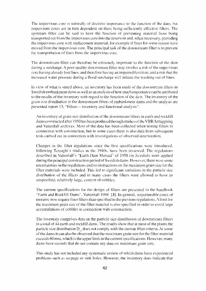
The impervious core IS naturally of decisive importance to the function of the dam, butimpervious corcs are in tum depcndent on there being sufficiently cffcctive filters. Theupstream filter can be said to have the function of preventing material from beingtransported out from the impervious core into the rcservoir and, whcn necessary, providingthe impervious core with replaccment material, for example if fines for sorne reason havemoved from the impcrvious core. The principal task of the downstream filter is to preventthe transporration of fines from the impervious corc,
The downstream filter can therefore be extremelv important to the function of the damduring a surcharge. A poor quality downstream filter may involve a risk of the imperviousCOlT having alrcady lost fines. and thcrcfore having an impaired function, and a risk that theincreascd water pressure during a Ilood surcharge will initiate the washing out of fines.
In view of what is stated above, an inventory has been made of the downstream filters inSwedish embankment dams as weil as an analysis ofhow much importance can be attributedto the results of the inventory with regard to the function of the dam. The inventory of thegrain size distribution in the downstream filters of embankment dams and the analysis arepresented report 13, "Filters - inventory and functional analysis":
An inventory of grain size distribution of the downstrcam filters in earth and rockfilldams constructed after 1950 has been produced through studies ofthe VBB Anläggningand Vattenfall archives. Most of the data has been collected when testing filters inconnection with construction. but in some cases therc is also data from suhsequenttests carried out in connection with investigations of obscrved deterioration.
Changes in the filter regulations since the first spccifications wcre introduced,following Terzaghi's studies in the 1940s. have been revicwcd, The regulationsdescribed in Vattenfalls "Earth Dam Manual" of 1958 (in Swedish) were appliedduring the principal construction period of Swedish dams. However, there were sameuncertainties in the regulations and no instructions on the maximum grain sizc for thefilter materials were included. This led to significant variations in the particle sizcdistribution of the filters and in many cases the filters were allowed to have anunspecificd, relatively largc, content of cobbles.
The current specifications for the design of filters are presenred in the handbook"Earth and Rockfilt Dams", Vattenfall 1988 131. In general. inipermeable cores ofrnoraine now require fincr filters than specified in the previous regulations. A limit forthe maximum grain size of the filter material is also specified in order to avoid largeaccumulations of cobbles in connection with construction,
The inventory compriscs data on the particle size distribution of downstrcarn filtersin a total of 44 earth and rockfill dams. The results show that at most of the plants theparticle size distribution D 15 does not comply with the currcnt filter criteria. At sorneof the dams it can also be obscrved that the maximum grain size for the filter materialexceeds 60 mm, which is the upper limit in the current specifications. However, manydams have records that do not contain any data on maximum grain size.
This study has not included any systematic review of which dams have experiencedproblems such as seepage or sink hales. However, the inventory does indicate that
42
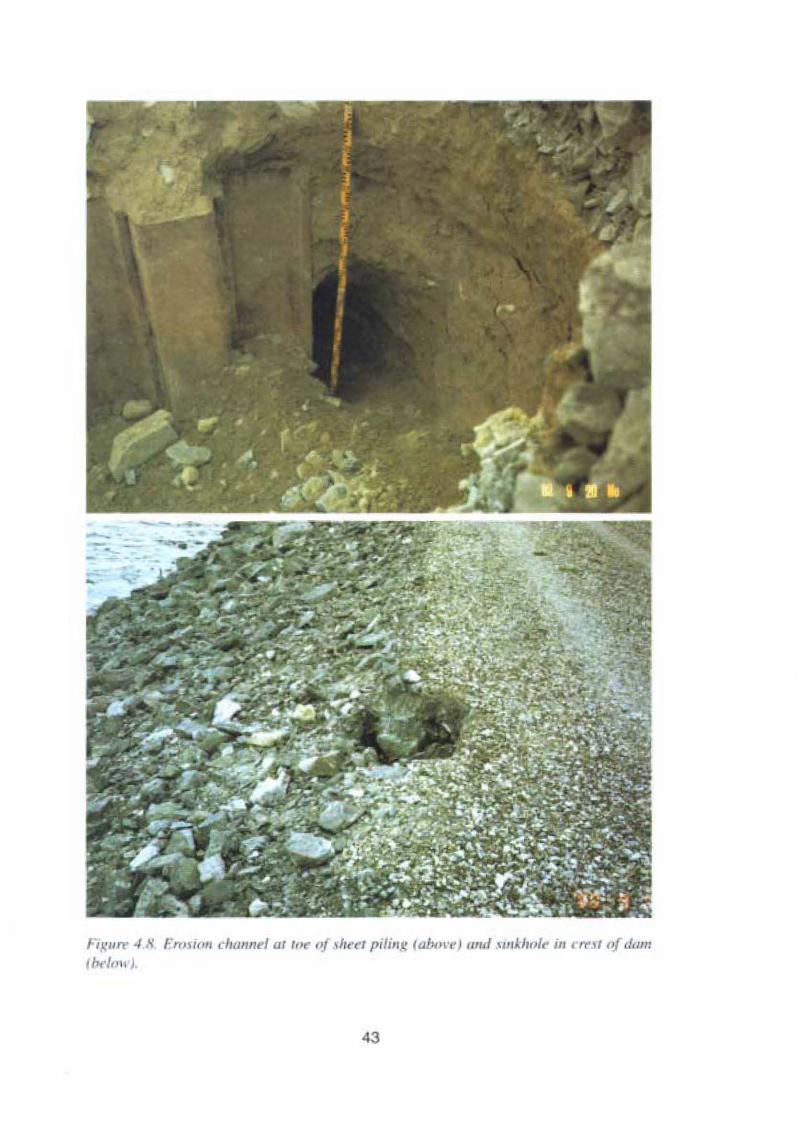
Figun: -I .•~ .r,H;" /II/IInd ut ro f) IIr""1 f'i/jll~ lubm'l'} III/JI ",.11",/.' iII r rrs t (~r dl/III
fbel.'" J,
43
Assumed pore pressure line during major leakage
Slip surfaces for stabil ity calculations
Supporting shoulder
Blasted rock
Filter
Figl/re 4.9. Reinforcement ojdownstream slum/der and toe with a retaining hank.
dams where such damage has occurred have downstream filters, which are among thecoarsest of those listed (see fig. 4.8). There is also information from the examinationof some dams with such damage, that the filters had both agenerally coarse level oflarge Dl) and a large content of cobbles, leading to separation with accumulations ofcobbles.
In those cases where the requirements made in the new filter regulations are not met, greaterattention should be given during scheduled and routine inspections to detecting the onsetof internaI erosion or seepage at an early stage. In addition, increased instrumentation canin many cases be recommended - in the first instance for seepage measurement. Forcmbankment dams in which the stability is not secured in connection with major seepage,reinforcement of the dam toe or the construction of a retaining bank of riprap on thedownstream side of the dam may be considered in order to increase stability. (See fig. 4.9)
It should be pointed out that the quality of the filter is very important also at normal waterleveIs.
Experience also shows that restrictions should be applied in addition to those specified inVattenfall's manual from 1988.
4.11. Ageing of embankment dams
When analysing the capacity of embankment dams to with stand new loads, it is of courseimportant to consider the changes that may have taken place since the dam was built whichmay be attributable to age. This applies to the dam as a whole, but since changes in theshoulders are easier to discover during inspections, etc. it is largely changes in theimpervious core and filters that are of particular interest since changes here are difficult todetect. Ageing is defined as the kind of changes that have a negative effect on dam safetyand which occur more than S years after the dam was completed.
44
Consequcntly, these quesrions have been investigated in a study by rueans of an inventory,which was carried out by sending a questionnaire to those people responsible for the safetyof dams higher than 15 m and to those who are ~nemhers of the Swedish Power Association.Subsequently, a eompilation was made of all the answers received, which were thenanalysed, An inventory and analysis of changes due to age are presented in report 16."Ageing of embankment dams":
The effects of ageing on Swedish earth and rockfill dams have been studied hycompiling the answers to an inquiry sent to owners of dams higher than 15 m.
In Sweden there are 119 earth and rockfiIl dams higher than 15 m. However, ifdeterioration was observed in lower dams, this information was also collectcd andincluded in the result.
The result of the inventory show that a total of 84 earth and rockfiIl dams, of which68 were higher than 15 m, had experienced sorne kind of ageing. The degree ofdeterioration varied to a great extent. In sorne cases erosion had been observed inriprap protection on the upstrcam slope of the dam. These types of deterioration havelittle, if any. influcnce upon the safety of the dam.
The ageing cases were grouped into 13 different types. Surface erosion was found tobe the most common type of deterioration. After that came sinkholes at the crest orshoulders of the dam. Sinkholes were in many cases reported to occur in cornbinationwith other types of ageing, e.g. seepage in the foundation or in the dam body.
Internai erosion is, aceording to statistics reported by ICOLD, the cause of a largeportion of the total number offailures in earth and rock-fill dams. InternaI erosion islinked to the cases of sinkholes and seepage reported in the inventory. Attentionshould be drawn to the se types of deterioration, since these in some cases eouldseriously affect the safety of the dams in question. The amount of seepage and theerosion resistance of the materials involved are factors that affect the development ofa possible failure.
The deterioration cases were almost all detected by "direct observations" in connection with plan ned inspections by operators or engineers. Thus, the surveillance of thedams is very important from a dam safety point of view. However, additionalinstrumentation should be considered in order to discover the ageing at an earlierstage. As a first step more dams should have a system installed for continuous seepagemeasurcmcnts.
Finally, the necessity of research regarding the ageing of embankment dams isdiscussed. It is proposed that the ageing phenornenon, which is difficult to detect,should be studied in order to reach a better understanding as weIl as obtainingappropriate methods for detection. Details from where the problems have occurred,e.g. the quaIity of the downstream filters in existing dams, especiaIly in the vicinityof eoncrete structures, should be studied.
45

The report confinns that with time. certain changes take place that may be of importanccto dam safety, which means that in general it is important to considor changes inembankment dams and in particular in connection with investigations inta the capacity ofa dam to withstand a flood surcharge. Il is also stated that the inspections by operators andengineers are important for the detection of damage and that increased instrumentation canin many cases be recommended.
46
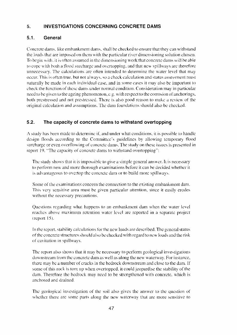
5. INVESTIGATIONS CONCERNING CONCRETE DAMS
5.1. General
Concrctc dams, like embankment dams, shall be checked to ensure that they can withstandthe loads that are imposed on thcrn with the particular river dirncnsioning solution ehosen.To begin with, it is oftcn assumed in the dimensioning work that concrete dams will be able
to eope with both a tlood surcharge and overtopping, and that new spillways are thereforcunnecessarv, The calculations are often intended to determinc the water level that mav, .oecur. This is often true, but not always. so a check calculation and status assessment mustnaturally be made in each individual case, and in some cases it may also be important tocheck the function of thcsc dams under normal condition. Consideration may in particularneed to be given to the ageing phenomenon, e.g. with respect to the corrosion ofanchorings,both prostressed and not prestressed. Thcrc is also good reason to make a review of theoriginal calculation and assumptions, The dam Ioundations should also be checked.
5.2. The capacity of concrete dams to with stand overtopping
A study has been made to dcterrnine if, and under what conditlons. it is possible to handledesign floods according to the Commiuees guidclines by allowing ternporary tloodsurcharge or even overflowing of eoneretc dams. The study on these issucs is presented inreport 19, "The capacity of eoneretc dams to withstand overtopping":
The study shows that it is impossiblc to give a simple general answer. It is necessaryto perform new and more thorough examinations before it can be decided whether itis advantagcous to overrop the eoneretc dam or to build more spillways,
Some of the examinations concern the connection to the existing embankment dam.This very sensitive area must be given particular attention, since it easily crodeswithout the necessary precautions.
Qucstions regarding what happens to an embankment dam when thc water levelrenehes above maximum retention water lcvcl are reported in a separate project(report 15).
In the report. stability calculations for the new loads are described. The general statusotthc concrete structures should also be checked with regard to new loads and the riskof cavitaiion in spillways,
The report also shows that it may be necessary to perform geological investigationsdownstream from the concrete dam as well as along the new waterway, For instance,therc may be a number of eraeks in the bedrock downstream and close to the dam. Ifsorne of this rock is torn up when overtopped, it could jeopardise the stabil ity of thedam. Thercfore the bedrock may need to be strengthened with concrcte, which isanchored and drained.
The geological investigation of the soil also gives the answer to the question ofwhcthcr there are some parts along the new waterway that are more sensitive to
47
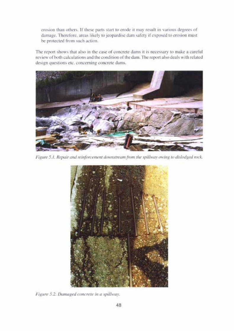
crn-io n tha u uthc rv. If thesc p"rh vturt tl' e rod il tII~y resulr in vaiious tle~l~es of
d:lIllug~ , lll"rcj",C . "fl"'" l ike ly I.. j'"I'P:lrJ"" dam , are t) if ", po..ed ll) cruvion mu- t• pro tecied Irnm such acrion.
n ie r"pon shllw. th,u .d,,, In rh " ISe Il f UHl reie Jan" il is necc-s r)' lo mak a lIr ~iu l
re vie .... uf hull, ca it'ulal iOllS a ll<J the cumJil illll ut Iii" J '" I1. n ie report a l", . <Je.d , wrth re lutcddC"1 1 n [uevtiun.... etc, .uncernine t:\II1crete mn~.
,. ...~ Ilr.. . ~ . /hl/l rJI crd I l>IUT(' / i ll a spiltwav.
48
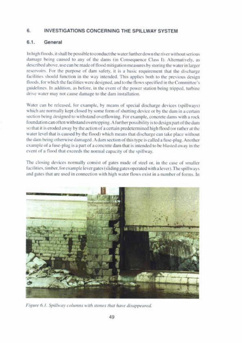
6. INVESTIGA,nONSCONCERNING THE SPIU WA,V SYSTEM
In" ,~h II.."h." ,t\ooll l>< p"'''hl<t" 00I'Id...1,h<'" , "" ,,,nh<, ,k,~ , '11< n ,.<, '" II ...., ,.,,;,..'J, ,,,,!,,, "" ,n~ e."-ro to ."~. of ,..' J,,,,,, "" ("",,~",,",., (l", l) "'lOel1l."w l~. Ib.....".·nt..-.I ..1-.,,<,"",can h<m.>do<,~ tl.,oj"""••",In no" ,n"" "~ """n~ ,t.:w"" m I.i,~<,
""""'" '' h .. ,h< "'''I''''''~ J, m "'fe',-, ;, ;, .1..,';' ''''I"''''''''''" ,h..>I Ih< 01.....'10.'.<10,',1""" , !>.. loJ I'"""t".. In ,h< ~ .~ .n'<r-.J.-.I. Th " "f'I'1.." "<n " , t'" I'f\'" , ..' <k,,~"
~..""', f... wnKh.h</ac ll'h '" "ot< ok"I''''--.l, , ,,.,l " ,,"" f1< ,~ , 'l"'·;r...1on , h<- r "mm,no,'-,~ ",": I ,,,,,, ,,, ...1"",,, .. 1><1.'« , ,n ,.... « en' "I ,h< P""''' "..h'''' I><In! "'1'1"--.1, '",/,,""J "'e ~,t<' """ "'. ,',"",d.d1"'t'" lO,h< J.un ;n"..II"," ",
\\ ,',' ,.., I>< "..lc.~. h. <'''''r'<, n1 n",.n, ,,[ '1'<'.,., J".-I...~ .k ,'~ "l"lIu~"
~'h ,d,",< n"f11",'I~ ~,.". , ..""J 0\ ~""" " " ," "r,"""mg .k,""< "-0) ..... ,,"on '" ..-«1.",""',,m h< , ,,~ ,....,~""" '" ~"o,,",nJ "'<rIk"",n~ . hl<<' ..mr'<." ....."'t< "","' """10.""'j,,,,,,"J.!I"'" <. n..11<n ~,,"""' oo ",<n,""';n~ . ,\ rnn h<r l'"",h< I"Y" ~, ok>i~n I"'" 01 ,..' dnm," ,h.. II "",,,d..J ' ~')' "~ ' /'<I" """ '~ " 'm"nprNctcmllllCd h ,~ " n.-...l ,... ,..I>< r .. ,I><~ ..<, k,d ,t\oo, "'"'. ..... ~) ,I>< n.., I, "'n",h "'.,, ", II... ,t hdl.'~' e .n '"'< plo• .-. ~." ....,,I><d" " h<,"~ ,.h,.""", olam,~<d. "',,",m '''''K'''~ III" 'H" ;,e" II.-.I. t'"",_"I"~ . .~"" ""
.",,"pk ,,' • 'n"'-J" u~ ". """ ,"" .«...-"',<olam 'n" ;' ,n,<nJo.-.I ho "" "'",.-oJ '''' '.' '" ,h<,,<nt ,,f. n,,-.I,~.. <, .«Jo. ,.... ",~m,1 ,'_" t~ .... .'" '1,"",.,.The ,'I ," ;n~ ok,,,'" """""II, ,.,,,,,,,, '..- ~..« nud< of ,,,,,,I ,-". ;n "" "'''' ,,[ , ,,"' Ie,I"" ,I" '"" ""oh<" t,~" "",pk"',C<""'''' "I,J mn ""·" 'l"" " '-.I "''' I> . 1..." .n"" ",II", ' ) '.nJ ~..." ,hol "" "",J '" ,""","~''' ,,, ~ l1h " ,~h ~ ..k'1 ~,... , . ,," '" • ""mh<, ,l (.-.m, . In
I " u,," ~.I .lriJl" "", .~.",", • uh >r,.,,, ,,",,h.,," """f'I",,,nJ.
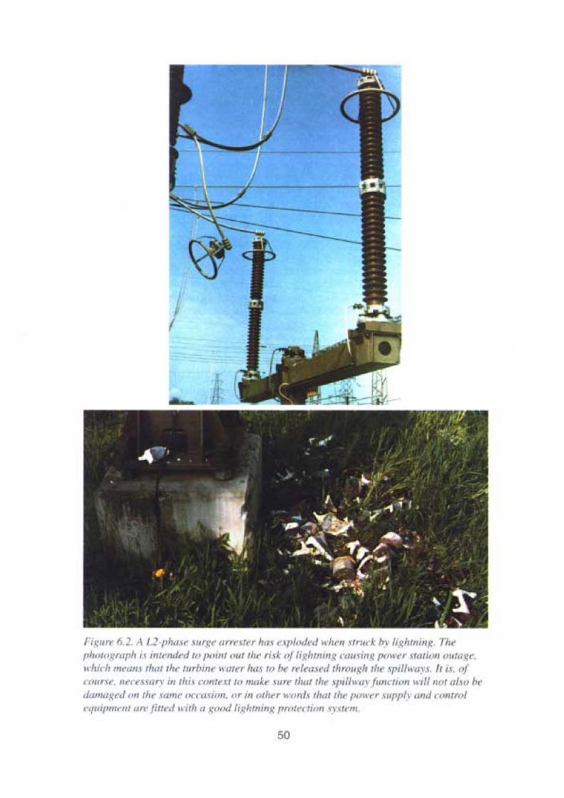
1'i~1I rt' ti.J.. A I.~ -"I",u .w ' g" arr,-'t,. , Iraf ,·.II,/,',I<'.l h'Ir,." ", 1 k by 1if,lJmil/!!" TlI"l"wtll}:"'riJ i" intrndrd to 1'''lI't "rtl th« ris): IIJ 1(~iJ lll illg c(///\ ;rr ~ I'"\\,,'T \·tlllioll (lll ltI~ " .
whlcl) m,-'IIl,' ,II(/t thr turbinr h'tIt..r IItlI '" f,,- r"'''''.I,-,1 '"rot,gll Iii .. Irif""'I."'. fr 1.1. r>jo m" ,. ' ..·.-e.l m"· ln th iv cont..U w /lir/k, III '" IIUlt th.. '/,111 1'''.\ [unruon "'111 110' IIf", l,,.ddIJUIL:t-a .m thr sam r Iwnui"JJ. o r in othrr wo nl v th.n tb» IU) H'('r HJP1'(\ (Hul ont ro]c'qrr'l un,'UI , ~n liuf-4J ~dth tJ good J;.~111J1ilI. I f,ro ,tr-rti rl1l x.y.u"..m
50

this context. gates also exist for other purposes. e.g, bottom outler gates for releasing the lastwater remaining in the rcscrvoir, but which are not intended to be opened at full waterpressute and for this reason cannot be uscd during a high Ilood. Therc are also skimmergutes, i.e.log floating gates, which are (or were) used for logging operations, but which havea limited discharge capacity.
Watcrways downstream from spillways must of eourse also be ablc to withstand the effectsof the flowing water throughout the period in question.
The Committee 's guidelines specify that only discharge from spillway devices, which canbe used with full rcliability and at short notice may be included in the discharge capacity.Thcy shall of course also have the capacity assumed in the dimensioning work.
The expression "with full reliability and at short notice" has been discussed, and theinterpretation that has been made can, with respect to dams in Conscquence Class l, besummarised to rnean that there should be redundancy with rcspect to for example powersupply in order to open the gates and thai "short noticc" should be seen in relation to the rateat which the water level in the reservoir rises and the capacity of the dam to withstand aternporary surcharge. The requirements will be formulated in guidelines that are workcd outjointly within the power industry.
The rate ofwatcr rise is normally (during river dimensioning) calculated on the basis of thedesign scqucnce. If the rate is low, there is a chance for certain mensures to be taken forcxarnple the connection of mobile power supply. Il should be notcd that according to theCornrnittee, the design flood has a certain charging period and that there is thereforc achancc to take certain action. such as incrcascd manning of the stations. At the same time,there are restrictions in the resources with respect, among other aspeers. to personnel, sincea design tlood concerns several or sornetimcs all the power stations and regulation storagesin the river in question.
Furthcrmorc, in certain cases redundant power supply (or some other system) is requiredin order to open gates which can cope with discharging turbine drive water when a stationis sudden ly switchcd off. In this case the rate ofwatcr risc, ofcourse, is the important factor,The redundancy requirernent has often been solved by installing two separate power supplysystems - one bascd on direct CUITent and the other on alternating current - which normallyopcrate on different gates.
As regards the demands for availability of the gates, therc are also differenees as a result ofgeographicallocation and thus associatcd temperature conditions. The probability of a highflood concurrent with conditions, which mean that gates may be frozen in place, requiresanalysis from case to case. This type of event may be rnore likely to occur in the southernparts of the country.
In connection with work on spillways and waterways, it is important to take dam safety intoconsideration by making a careful analysis before the work is started. Examples of suchmcasurcs could be not to work on several spillways at the same time, to have a standbypower uni t available at the gate, to have extra personnel on duty for the event of anernergency, etc. Carefully considered planning eould also significantly reduce the risks. Forexample. when rcplacing the wires on a gate. the new oncs should be on the site and checked
51

Fjgun' 6.3 . TiJ machinrrv (Jf,~f' j/hnl\' ~<11~.< ofT rr 1I0J <1"')1111' Ctl"JJ , .,,' ,T"',/IIk i" onlr tomak,' jr 1",·....r1>/,' to "IJ"" Iii. ~rllt'!{ /J"Til III.. 1',,,,,,' wl,l "rtr'~'II" I'",,','r Il/H'" jllj/..L1 IT i,lrerommendrd If> n 'pIll" ,Tir lumdl with nn ..lrctri« IlltJI"'; II ilil'l, ('(111 1, 1"'11 ' rrd "1/1/ th«rlcrtru : .\T.' "U 'frI il! (I rur (Jr lir! rotnvulrnt .{."-fu',.r
betore rh nid "ne~ n: re: moved. •mdalsoonIy one wlre should be l e 1110 V d and the II \~ onin t a l l e d . forc t h e n ex t Ll nl'l~ r c m oved. CK' . l'IlIC des i u u otthe~lI1C ha, iL' a r u l e been made
such. that one wir' " c noug h In n pcn il).
II il n,'. Ihe intention 01 thi s report serie. to determ ine J m;Lnd, in conncction WIthrcdundancy, for cxamplc. fur darn-, in diff erent consequence d asscs. This will he done a,,"' 11 nI' a seeond prnjcct. klO S 1111 1. which il in progress wirhin the power industry amiI r which the reports of this P'Oj" I , erve as inpul.
' I h-c ICJ1<l1l le ne, mctudcs reports 0 11 how the uClUlIJ dischal}:c cap"c i l~' " r xpillway» isdcrcrrn lncd,on rhe fu nct ionnl safery Of lhc <p lllway !!:l1C~ ,1I1U on the precond irio ns CI~ , f",the u-c of fusc-pluas 10 merense the disca,u e capaciry, The DCI artment ur Hydra nlicEnginccring at the Royal In ritute (1 Tcehrmlogy in Sh..:lo.hultll h.IS. with sUJ1 111 from the!",wer i nd ll s, ~'. s1U lied the r ossioilil) 01 uslng siphon vpillw öl}" 101' lhi.' same plIrpose.\\ lnch al,,, could be nf interest 111 1.
A sumrnnry j, given below oI' Ihc report- wrinen on the subjec: and al,o a 'IUJ~' "r thetcchnicnl potential fnr di.<charging rhrouph turnines. "'h ich has been earned 0 11 1within thisi ll\'e"iligalinll wnrk
52

6.2, Real spillway dls charge capacity
111 connccuun "' llh the work on :luapu nj1 the dam s lO ne w desrg n l100tls In :I C~ord;1I1 e withthe Comminee' s uuidel lu . • 11 i, imponam to usc mo CO/Te [ vulucs for the dischargecap:! Il)' of~pillways , Discharge wiII nunual ly lake pla c al a hiehe r wuter le, d (and hiehert lnw I than was o rigina ll}' a. SU1I1ctl, ' 111i 1101'11lally 1I1<':1I1S that the e ' i' lillg di,charge curvehas lo be exr rapola ted . Revi w of rhc spil lway capoci ty ca lc ulations have iII lIIany casesshown il to have been o vercsn mared ami pillwuy l e , ts with hi uh di. cha rtics hav e oftenrevenled design and con, rrucri n mi lakes. 1\ stu dy has rhe rcforc bee n made on how theact ual discharge e"l)ad'y .hnukl be de termined. which is prc -eutcd in report 5. " ReOl I
spillwuy discharge capacity":
T he report defi ne» I",U kindv uf 'pi llway Jisch.lrge ...a pac itie s 11'0 hyd ru ul lcSpill\\llY· cnpuci ty is in Ihis report de fi ned as II~ theoretical discha ree capac it orthesrruc turc wuh no regard lO res tn erlons iruposed by crosion. utundation, vibrntions e tc.o n [h" " ii i",a)' " r i l , -urrouruhnes. The tech nlca l s pllhu I) L~I It;ldt) is here defineda, the disc harge l~l l'aC i lY \\ illl reganl Iu suc lt lt!slr icl iug rad llr' .
53
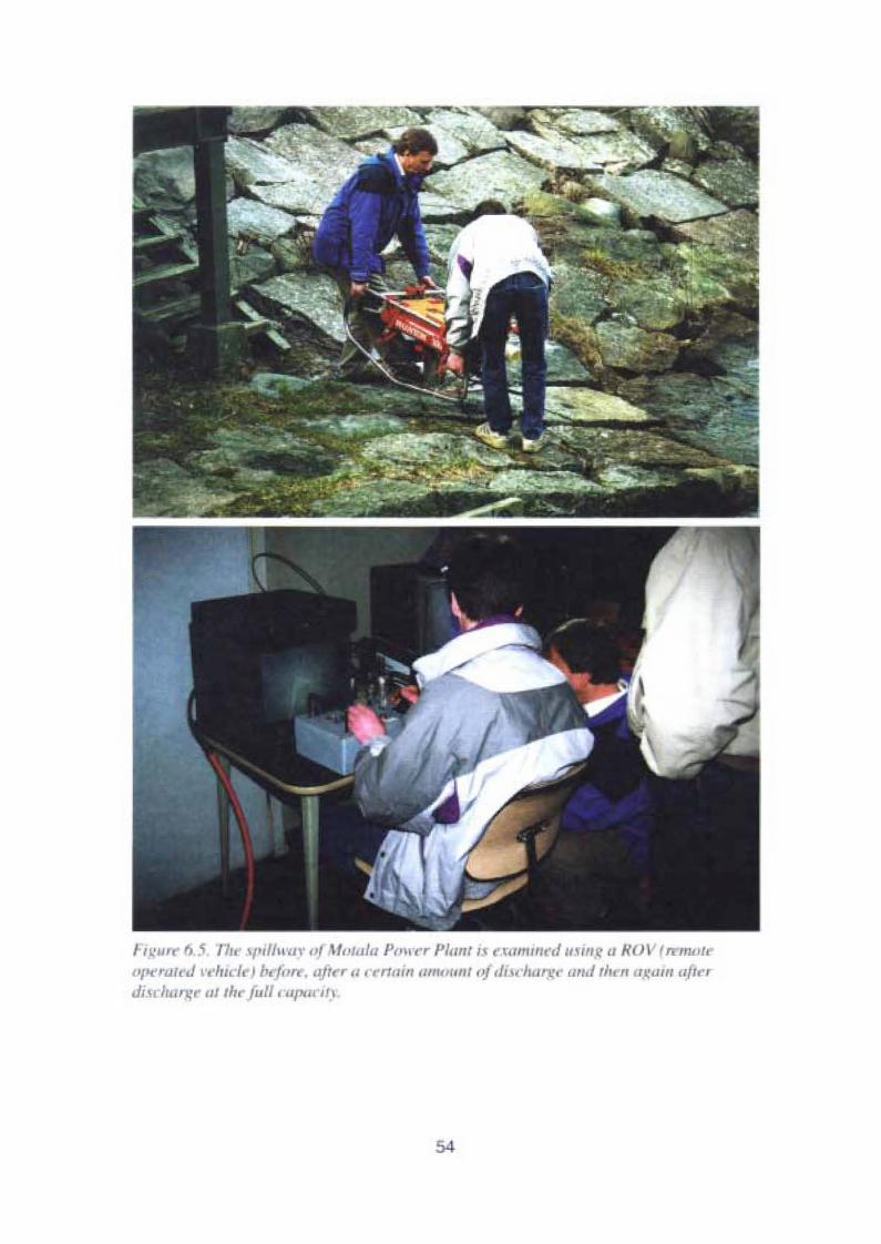
fi.~u', fl 5 Thr ".,I/"'UI' oj HoIU/U 1''''....r 1'/1/1'1 i, I<1/IIi",'d millg <I HUI' i remotr,,/ ,<'ra lr .! vchtc! ! bcfor«, "JI" II, r rta in om",o,1 oj di'dul/x" '/II,/,h. II u,~.JII' aftrr
di H tu '11" ut tlu fult "tll"'ClJ.l
54
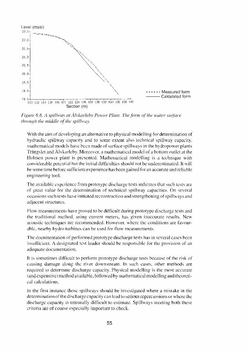
Level (masi)22.':;-
-=~-
22.0
21.5
21.0
20.5
20. Oj
'"'I::: " '"110 112 114 116 118 120 122 124 126 128
Sectian (m)
j i I I
130 132 134 136 138 140
- - - - - - Measured form--- Calculated form
Figure 6.6. A spillwas at Älvkarlebv Power Plant. Thefonn ofthe water surfacethrougli the middle of' the spillway.
With the aim of developing an alternative to physical modelling for determination ofhydraulic spillway capacity and to some extent also technical spillway capacity,mathematical models have been made of surface spillways in the hydropower plantsTrängslet and Älvkarleby. Moreover, a mathematical model of a bollom outlet at theHolmen power plant is presented. Mathematical modelling is a technique withconsidcrable potential but the initial difficulties should not be underestimated. It willbe sorne time beforc sufficient experience has been gained for an aceurate and reliableengineering tool.
The available expericnce from protoiype discharge tests indicates that such tests areof great value for the determination of technical spillway capacities, On severaloccasions such tests have initiated reeonstruction and strengthening of spillways andadjacent structures.
Flow measurements have proved to be difficult during prototype discharge tests andthe traditional rnethod. using current meters, has given inaccurate results, Newacoustic tcchniques are recommended. However, where the eonditions are favourablc, nearby hydro turbines can be used for now measurements,
The documentation of performed prototype discharge tests has in several cases beeninsufficient. A designated test leader should be responsible for the provision of anadequate documentation.
It is sometimes difficult to perform prototype discharge tests bccause of the risk ofeausing damage along the river downstream. In such cases, other methods arerequired to deterrnine discharge capacity. Physical modelling is the most accurate(and expensive) method available, followed by mathernatical modelling and theoretical calculations.
In the first inslance those spillways should be investigated where a mistake in thedetermination of the discharge capacity can Iead to serious repercussions or where thedischarge capacity is unusually difficult to estimate. Spillways meeting both thesecriteria are of course especially important to check.
55

Figur 6.7. Spi /IIL 'uy ...here the ....el \IYI.\ Ilamt/g,'d drt r ; l l j? «t«. 1.
-111<" iIlVC'lig;Ilillll , hll"'" Irull , .1 il ru,', nor alre uly h'~llm'll l~, '1 review : noulJ~ earned (11.11 u lthe li 'chll l'J.l ~ ' ''P'' ily01the spillwuys In Ihi> context. ensideration should be given 10 thoscfa~lors th"l mc specifled in rh • rcpOI1 This ,Ipph~s .lb(, lo <1.1111< nf Cl' Il' C'l lICIK'C' el.ls, II ••dlhllugh dum, 01COIl"'tI" mce 'Iu" I should be given pnurny, espcc mlly thovc th.u aredilf ·ul. Il a,scs~ correctly,
6.3, FunCllonal relIabIlIly of splllway gales
lC Conuniucc's euiucllnc- P'C ' Upp"'c. a pcciflcd ubove. lhllt " li ly lhu-e <.lis ' Iliug"dc viccs ,, 11Ich 1::111 be: used with lull rcliahiluy and III short notice rnay be: in luded incalculationvofdischarge cap, uv.A stud)' ha, thcreforc been made rcgardinp the tun nunalrcliabrlily III g.lt.:-" " hich b presenred iII Icpou 7. "Fuuctiunul i el iuhi litY•'[s pilI\l ny ~ lIle ,""
The ii rvI slllge 01 the illlcsri!!:llio!l consistcd III' collccnng iuformat ion on Iaulttrcqucncy, tbc most common taults and also possible breakdowilSofCXlstilll!spillwa~
~lIle' il ' .10 inqutry covennp major hydropower an I watcr r ~\l l a.ion enrcrprisc inSweden. The inquiry was tullowed l ~. pcrsoual visil" and rclephonc intervicw toensure n 1110 1 derai led comprlarion of ra IS. TIll' In \' CS" rat ion was subsequem lyextend LI ini" :1 ,c.und sia 'e which pmp.. -ed TOe.IS UTe ' ••md luter 'll,n inc luded sorneel cnl "ee, atul s,afe.)' .U1ul)',j ,
The mvc ntnrie» ..r tIll Ils and "rnhlern, , hu""...1 tluu mo re xerinu 1116 ent' lirilreaktluwns d ue I" the I.IL: or ,'ale lunc nuns are very rare. The p,'",e r intillSIl)' Wllrk,on. 1:11111 ' i11m:llnlailling and impmvinp il high IC\'dufd iw harge ,afel~ , _tal"d bclow
are l tew urea! of specral importance or where pmhkms have proved ... hccomparativel ' u, ulI l and thu» shouhl bc ~' I\cn special auc rnio n.
56
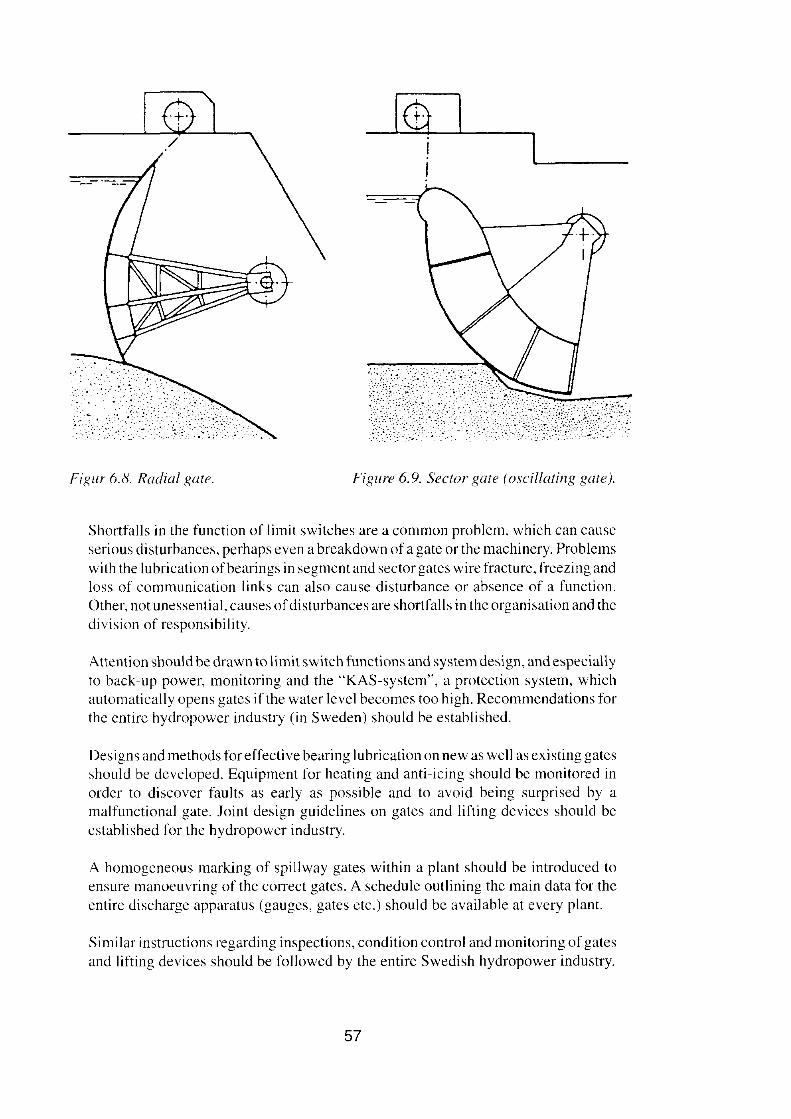
Figur 6.8. Radial gate. Figure 6.9. Sector gate (oscillating gate).
Shortfalls in the function of limit switches are a common problem, which can causeserious disturbances, perhaps even a breakdown of a gate or the machinery. Problemswith the lubrication ofbearings in segment and sector gates wire fracture, freezing andloss of communication links can also cause disturbance or absence of a function.Other, not unessential, eauses ofdisturbances are shortfalls in the organisation and thedivision of responsibility.
Attention should be drawn to limit switch functions and system design, and especiallyto back-up power, monitoring and the "KAS-system", a protection system, whichautomatically opens gates if the water leve I becomes too high. Recommendations forthe entire hydropower industry (in Sweden) should be established.
Designs and methods foreffective bearing lubrication on new as weil as existing gatesshould be devcloped. Equipment for heating and anti-icing should be monitored inorder to discover faults as earlyas possible and to avoid being surprised by amalfunctional gate. loint design guidelines on gates and lifting devices should beestablished for the hydropower industry.
Ahomogeneous marking of spillway gates within a plant should be introduced toensure manoeuvring of the correct gates. A schedule outlining the mai n data for theentire discharge apparatus (gauges, gates etc.) should be available at every plant.
Similar instructions regarding inspections, condition controi and monitoring of gatesand lifting devices should be followed by the entire Swedish hydropower industry.
57

The frequency of training should be increased for extreme situations such as longterm power failures and large floods acting simu1taneously on several power stationsalong a river. Improved routines regarding the reporting of incidents should beesrablished within the power industry.
The aim of the work has been to provide basic input for analysing the safety and reliabilityof common types of gate system. The report provides reliability assessments and proposalsfortechnical designs and equiprnent, and points out the irnportance ofdetailed operation andmaintenance procedures as wcll as training, practice and preparedness for extreme situations. The report also disensses requirements for the organisation needed to maintain a highlevel of discharge reliability. The views may be of value in more general terms. but therernay also be other acceptable solutions.
On the basis of questionnaires and intervicws held with operational stall at a number ofpower stations as part of the project. fault tree analyses have been performed for differenttypes of gates. These are presented briefly in an appendix to the report. Fault tree analyseshave been carried out for the spillway gates in Yngeredfors Powcr Plant by Sydkraft andearlier by Vattenfall for Stadsforsen Power Plant.
The report will also be used as a basis for the joint work that is being carried out within thepower industry in Sweden conceming common guidelines for dam safety among powercompanies, which also includes a common incident reporting system.
6.4. Fuse-plug as auxiliary spillway
The new guidelines for design floods are expected to involve the need for increaseddischarge capaeity at a number of dams and same form of fuse-plug eould then be a goodsolution. A study has therefore been made of when this type of spillway can be suitable andhow the design can be effected.
The Committee's guidelines indicating that only those discharge devices which can be usedwith full reliability and at short notice may be included in calculations of discharge capacitycan, depending on the conditions at the dam in question, be solved with various technicalsystems or by a high leve! of preparedness. One alternative could be to have an ernergencyspillway that opens if the normal spillway fails to open as intended. This spillway could beof the fuse-plug type, the activation of which could be either autornatic or manual.
A study on the question of fuse-plugs is presenred in report 8,"Fuse-plug as auxiliaryspillway at existing Swedish dams":
The stud y consists of a general analysis of the fuse-plug spillway and of its potentialas an auxiliary spillway at existing Swedish dams in connection with the applicationof the new Swedish guidelines tegarding design Hoads. Erodible dams as a particulartype of fuse-plug have been considered as being most appropriate for use underSwedish conditions and are therefore described in more detail in the report.
The repan gives recornmendations on the design of fuse-plugs that are to be built atexisting dams. The repan also shows how to conduct the analysis and the choice ofwhich type of spillway is most appropriate for use as an auxiliary spillway. Problems
58
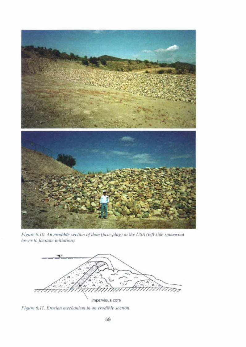
r, 'u " ," I (J ( 1/ ar -dtb! " 'U/"" or.11111I u» " ·'I"u.III i" II,,' U 'fl 1I[:fr vide somrwhat/0'" r to [ariun, initiation ;
,
trnpervious core
Figur» fl , II /OI",i"" mccluuu . lir III "'I ..n,hh/t· v aio».
59
that have been less studied and which are specific for Swedish conditions, e.g.freezing of the material. as weil as new problems appearing when a fuse-plug isintroduced at an existing dam are also mentioned.Some of the recommendations and conclusions of the repor! are as follows:
As a result of the ongoing river dimensioning review based on the new Swedishguidelines regarding design flood, sorne of the dams may be used for f100d mitigationand othcrs may need to be provided with an increased discharge capacity.
In cases where the discharge capacity has to be increased, the choice of a Iuse-plugas an auxiliary spillway may be advantageous if the floeds passing over it have areturn period of more than 100 years. The advantages are a generally lower cost asweil as the fact that the fuse-plug activation system is independent of the mamspillway activation system and usually automatic (self-acting).
The required discharge capacity during design t100d has to be unconditionallyavailable at all times. To guarantee this. redundant systems may be used for activatingthe opening systems for gates. An alternative solution could be to build an emergencyspillway, for instance a fuse-plug with an automatic activation system, independentof the activation system of the mai n spillway.
Many parameters and circumstances deterrnine the choice of solution, especiallywhen building auxiliary spillways at existing dams, and therefore each case has to bestudied individually. Besides the technical and economical aspects there are also legalproblems that have to be clarified as weil as psychological effects on the populationliving in the vicinity of the dams. The fact that the expericnce of building andexploiting fuse-plugs is lirnited makes the analysis of this solution more difficultcompared to others.
When adapting existing Swedish dams to the Cornrnittee's guidelines, increased spillwaycapacity or emergency spillways may be required at some dams. Inthese cases, a fusc-plug,for example an erodible section of the dam, may be an alternative. The report analyses thepreconditions for this solution as weil as its advantages and disadvantages. Various typesof problems and solutions that are covered in the investigation in connection with fuse-plugs(e.g. downstream erosion proteetion) mayaIso be of interest for other types of spillway orin order to study flows through dams. Studies of the function of an erodible section of dammay also be of value for dam safety analyses in general.
When ehoosing solutions, it is important also to deal with problems that occur in connectionwith unintentional activation and, as far as emergency spillways are concerned, the case inwhich not only the normal spillway but also the auxiliary spillway opens by mistake. A riskstudy of the alternatives is recommended.
6.5. Discharge through the turbines
During the coursc of the Cornmittee's work, it was discussed how to view the question ofwater release through the turbines, and the Committee decided, with the justification thatit would be reduced owing to a high tailwater level, that it should not be counted in thedischarge capacity (during the calculation work it is (according to the guidelines) assumedthat the turbine drive flow will stop from and including the ninth day of the t100d sequence,when the extreme rain occurs). Another reason for not counting turbine drive flow is the risk
60
of a station being sh ut down (tripped). the prohability ofwhich is greaterduring a high flood
situation than under normal conditions. There rnay be stations, howevcr, where the tailwaterlevel has little or no effect, and at which it is thus possible to use discharge through the
turbines as an alternative to building a new spillway. For this reason. a case study has beenmade concerning the possibilities of using the turbine waterways.
In order to gain an overview of the potential and problems involved, data from a real hydropower station with Kaplan-type turbines has been used and alternative ways, in a high tloodsituation. of dischargirig through the turbines without connection to the grid have been
studied, i.e. without the braking effect of the generators. A shutdown of power plantsfollowing a loss of the grid must be assumed to be likely during a high flood situation.
The main alternatives idcntificd are:
- the runner blades on the unit are rcrnoved- the unit is locked to prevent rotation
- the unit is allowed to race at high speed without being braked
(There may also be alternatives incorporating house turbine operation and wrongly combined(over-opened) turbincs which, however, have not been studied in any greater detail).
As abasic focus for the study, a discharge (min 220 mvs) of the same size as the turbine drive
water tlow was selected. At a tlow that is so high for a measure of this type to be necessary,large head Iosses occur downstream in the case studied (a tailwater level 2-m higher than
normal). The upstream level isjudged in this case todepend also on the Iact that this increaseis nccded in order (togethcr with discharge through the turbine) to obtain a sufficiently highdischarge capacity at the spillways.
If the runner blades are rernoved, the now through the turbines wi II only be controlled bythe guide vane openings. It has not been possible to find any model tests that show the tlow
as a function of the guide vane openings, but it is judged purely theoretically to be possibleto diseharge 250 m'/s at the heads in question. In this case too, there will probably bevibrations and a risk of damage to bcarings, runner charnbcr, tailrace tunnel, etc. Whicheverrncthod is used to rernove the runner blades depcnds on how much time is available, but the
fastest and at the same time most drastic way would be to cut away the blades by earbon arecutting. The method rnay be judged as being Ieasiblc and realistic. but owing to the cost ofreplacing the runner blades and the risks involved in the dismantling operation, which is
expected to take place under watcr, the remainder of the study was focuscd on the otheral ternati ves.
In the alternative involving a permanently braked unit and runner blades opened to themaximum extent (and lockcd), the tlow is estirnatcd to be approximatcly l30m'/s accordingto mode! tests. Bcfore adopting this mcthod, further studies are required, for exarnpleconcerning locking methods for the shaft, load cascs, etc.
In the alternative involving racing without braking, two cascs can be identified:
racing with combined turbine
- uncombined racing
Following contacts with the manufacturer, it is decmed that long-term racing in excess of
twice the synchronous speed should not be allowed, which in the case studied means arestriction to 150 rpm. A reservation is, however, made regarding the possible harmful
vibrations and that the bearing temperature does not become too high.
61
In the casc of racing with uncombined turbine. the study showcd that in the mostuntavourable case the maximum speed would be rcachcd at a hcad of somewhat below 5m and the discharge would be approx. 240 rnvs. At a head of 7 m, the speed would be 190rpm and the flow approx. 290 rnvs. The runner blades and guide vanes are assumed to belockcd. The assessment made was that even if the dcsircd flow could be aehieved in thiscase. harm ful vibrations would be likely to occur, which could shake the benrings. runncrcharnbcr, tailrace, etc. apart. A limitation of the speed could be achievcd by throttling thetlow with, for exarnple, a tailrace gate,
In the case of racing with a combined turbine, it is decmed theoretically possible toachieve a now of 250 mvs, and up to a net head of 7 m a speed of 150 rpm should not beexceeded. In order to determine the now (i,e, how large a guide vane opcning can bepermitted), which can be released through the uni t without serious problems occurring. aplant test was deemed to be the most suitable solution, The continued work on the unitstuelied is being focused on this,
During contacts with turbine manufaoturers. it has been discovered thai model tests werecarried out for several French power stations during the 60s with regard to the possibilityof allowing the unit to race for a longer period and determining the now thai could then beacceptable, Several tests were also carried out on installations. The results of the testsindicated that cavitation problems and instability in connection with uncombined units arethe lirniting factors and that large runner angles are Iavourable in order to allow throughlarge tlows. A certain number of trials were carried out in cornbination with a throttlingtailrace gate, which gave very good results (quict and smooth operation even when racing).Flows up to maximum operating tlow were tested in this way,
The possibilities ofusing turbine waterways in combination with high tlows appeal' to existand can, at stations with favourable conditions, have a valuc both as part of the futuresolution for how to discharge the design tlood and to provide the chance to improve thepossibilities for coping with a very high tlood that occurs before the facilities have beenreconstructed, in which the discharge capacity shall be increased. Furtherrnore, the methodeould in certain cases provide standby capacity if one of the ordinary spillways is notworking. In order to avoid blocking of intakes, ongoing efforts will probably be necdcd toclean them throughout the period in question.
If it beeomes necessary to avcrt a dam failure with serious consequences, exceptionaldamage to turbines and generators can of course be accepted. A precondition for being ablcto usc this option is that a comprehensive review and documentation be made of how it canbe effected at the station in question and that the authority exists for making a rapid deeisionon action to be taken.
According to the assignmcnt, an analysis of the discharge possibilities through the turbinehas been conducted in the form of a short Ieasibility study and is not reported in any wayother than that outlined above. The work has been carried out by Vattenfall Vattenkraft incc-operation with Vattenfall Utveckling AB and Vattenfall Hydropower AB.
Il should be emphasised that the inclusion of discharge through the turbine waterways in thedimensioning work involves a departure from the Comrnittee's guidelines and shouldtherefore be approved by the VASa Dam Committee.
62

7. INVESTIGATIONS CONCERNING MONITORINGAND EXAMINATION OF EMBANKMENT DAMS
7.1. General
During adaptation to the Cornmittees guidelincs, the solutions in certain cases are judgedto involve mitigation by ternporary flood surcharge of certain dams. In order to be able tousc this possibility, a determination must be made of what technically the dam can actuallywithstand - on the one hand more theoretically with respect to the structure of the dam, etc ..as weil as on the basis of what conditron the dam is in. Furthermorc, it is important to be ableto assess the real cross-seetioris of the dam, in particular the levels of the impermeable careand the overlying filter as weil as any low points for these along the dam.
Status inspection is also important in the future in order to be able to detect and, wherencccssury. repair changes that may affcct the function of the dam both generally andspecifically in conjunction with a temporary tlood surcharge. Dams are also affected bychanges due to ageing, which means that the development of methods for monitoring andexamination that can at an early stage detect small changes is also of interest from the pointof view of general dam safety. The inspection of dams is earried out in different ways andwith somcwhat different aims throughout the lifetime of the dam.
During the construction stage, construction inspection is carried out and, in connectionwith the Iirst impoundment, functional inspection that then continues for several years aftercornmi sSlomng.
Following this, dams are monitored during the operational stage in various ways as part ofthe work on dam safery by means of operational inspections that are carried out at variousintervals, Ifdarnage is discovered, it is subjected to special examination. Simi larly, a specialinvestigation may be necessary if a study needs to be made of the capacity of the dam towithstand some form of new load, for example a l100d surcharge. Monitoring aims, at anearl y stage, at detecting damage so that repairs or same other suitable action can be carriedout at the right time. Monitoring also includes, for example, obsetving seepage through thedam and discovering settlements or abnormal rnovcments. Monitoring can with certainmcthods take place continuously in terms ofboth time and along the entire length of the damby instrumentation of the dam for e.g. leakage measurcment, whereby the water that seepsthrough the dam is collected at a number of rneasuring points. With other methods, themonitoring is carried out at certain intervals in time or at certain selected points along thedam.
If damage is discovered, there willnormally be an examination to determine the reason.extent and suitable mcasures in which context both well-tried, traditional as weil as newinvestigation methods can be used. Once the damage has been repaired, a new examinationcan be made of the area in question to check that the results intended have been achieved.
Certain methods can be uscd for both monitoring and examination. When selectingmethods, one iniportant factor is whether the investigation can be carried out continuouslyalong the entire length of the dam, for a plane through the dam, along a line or only give alocal random sample or a mean value for, for example, a certain part of the dam. Anotherfactor is what the method primarily investigates and what connection it has with the
63
condition of the dam. The more indirect factors are studied, the greater the risk can be ofother factors, irrelevant to the safety of the dam, having an influence on the results andgiving wrong indications or diffuse results that are difficult to interpret. In the same way,it is, of course, desirable that natural variations in the dam, for example regarding the levelofcompaction or water content, can be separated from Iaults and changes in the dam. Duringrepair work, it may also be of interest to be able to follow how, for exarnple, grout isdispersed and the effects of the repairs on, for exarnple, seepage. Tt is also of interest incertain cases to know how long it takes to obtain the results.
Of particular interest are certain methods that make it possible, after damage has beendiscovered, to compare a measurement over the area damaged with an earlier measurement(fingerprint) and preferably. by for example computer tomography, obtaining a picture ofthe change. It is important in this context for the mcasurements to be corrected for differentwater levels in the dam on the measurement occasions,
Costs and time expenditure are other important factors in connection with choice of methodand are strongly influenced by what measures need to be taken in the dam in order to carryout measurements. It is of course preferable that little or no measures need to be taken, forexample ground-penetrating radar measurement from the top surface of the dam or thatalready installed equipment can be used, e.g. water level tubes. Methods that requiremeasures such as sampling by drilling or the installation of new tubes for measurementalways involve undesirable encroachment on the dam structure and often high costs, whichmay limit their use to limited areas where damage is indicated in other ways.
During more recent years, the power industry in co-operation with the Swedish Council forBuilding Research and the Royal Institute of Technology have carried out a number ofprojects in connection with the status inspection of embankment dams, including groundpenetrating radar measurements for checking the crest level of the impervious core and theimpervious core from both the dam crest and between boreholes, which has made it possibleto carry out tomographic analysis of the measurement area. Furthermore, automatic systemsfor seepage measurement by the collection of leachate have been further developed andmethods for seepage measurement by the analysis oftemperature variations in the dam havebeen developed.
Within the framework of the present report series connected with the Committee'sguidelines, a study and compilation have been made oftraditional methods for checking thestatus of embankment dams and several studies concerning more recent methods.
International experience and the fact that the installations are growing older have shown thatthere may also be a need for a more detailed evaluation of the safety of the facilities.Vattenfall has started a successive safety review of its most important facilities. Theevaluations comprise for example a review of design data and comparisons with currentguidelines for construction and operational safety, but also an evaluation of informationgained in connection with status inspection. The studies carried out in connection withstatus inspection may also be of value in this context.
The investigations are presented below:
64
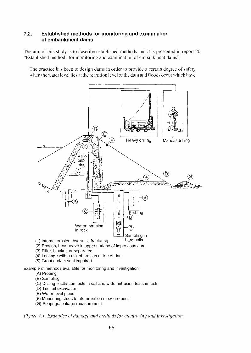
7.2. Established methods for monitoring and examinationof embankment dams
The aim of this study is to describe established methods and it is presented in report 20,"Established methods for monitoring and examination of embankment dams";
The practice has been to design dams in order to provide a certain degree of safetywhen the water leveIlies at the retention level of the dam and tloods occur which have
Heavy drilling
~ Pmb"9
~~ B
Water intrusion min rock ~ S B l' ,
amp Ing In(1) Internai erosion, hydraulic fracturing hard soils(2) Erosion, frost heave in upper surface of impervious core(3) Filter, blocked or separated(4) Leakage with a risk of erosion at toe of dam(5) Grout curtain seal impaired
Example of methods available for monitoring and investigation:(A) Probing(B) Sampling(e) Drilling, infiltration tests in soil and water intrusion tests in rock(D) Test pit excavation(E) Water level pipes(F) Measuring studs for deformation measurement(G) Seapage/leakage measurement
Manual drilling
Figl/re 7./. Examples ofdamag« and methodsfor monitoring and investigation.
65
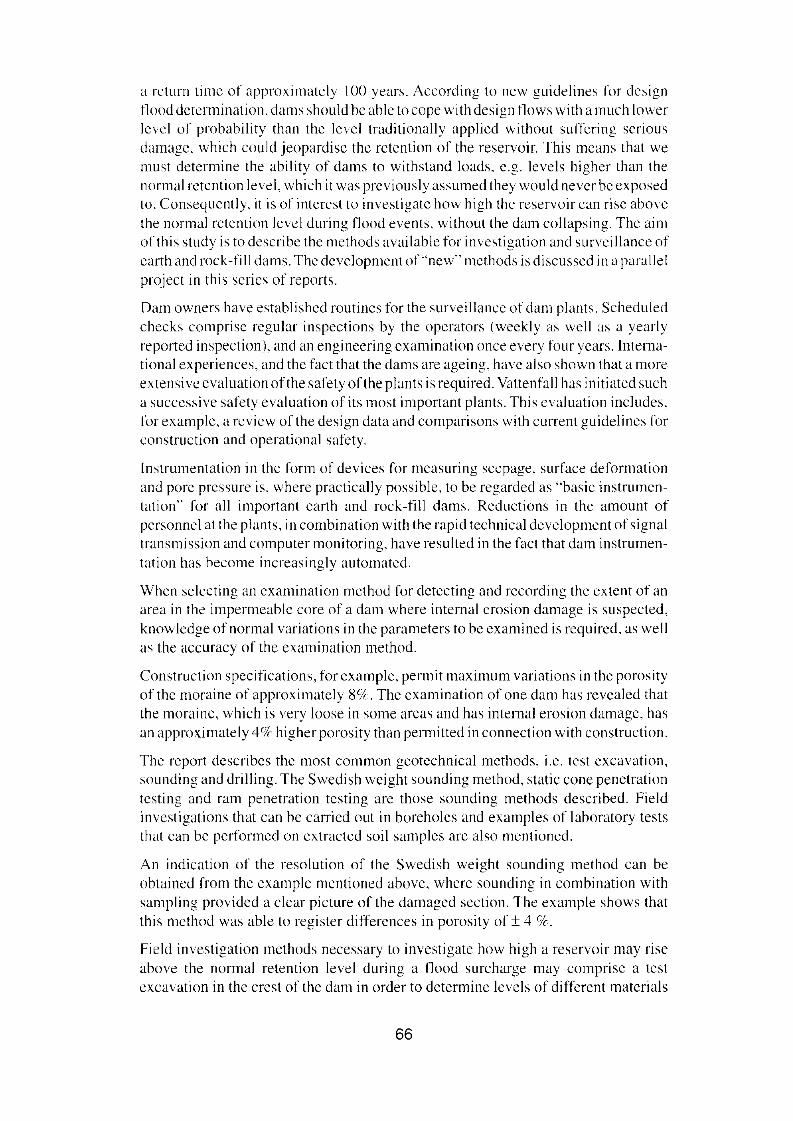
a return time of approximatcly 100 years. According to ncw guidelines for designflood determination, dams should be able to cope with design tlows with a much lowerlevel of prohability than the leve I traditionally applied without suffcring scriousdamage, which could jeopardise the retention of the reservoir, This means that wemust determine the ability of dams to withstand loads, C.g. levels higher than thenormal retention level, which it was previously assumed they would nevcr be exposedto. Consequenily, it is of interest to investigate how high the reservoir can rise abovethe normal retention lcvel during tlood everus. without the dam collapsing. The aimof this study is to describe the methods available for investigation and survcillance ofearth and rock-Iill dams. The development of "new" mcthods is discussed in a parallelproject in this series of reports.
Dam owners have establishcd routines for the surveillancc of dam plants. Scheduledchecks comprisc regular inspections by the operarors (weekly as weil as a yearlyreported inspection), and an engineering examination once every four years.lnternational experiences, and the fact that the dams are ageing, have also shown that a moreextensi ve evaluation of the safety of the plants is required. Vattenfall has initiated sucha successive safety evaluation of its most important plants. This evaluation includes,for example, a review of the design data and cornparisons with current guidelines forconstruction and operational safety.
Instrumentation in the form of devices for measuring seepage. surface deformationand pore prcssure is, where practically possible, to be regarded as "basic instrumcntation" for all important earth and rock-fill dams. Reductions in the amount ofpersonnel at the plants, in combination with the rapid tcchnical development of signaltransmission and computer rnonitoring, have resulted in the fact that dam instrumentation has become increasingly autornated.
When selecting an examination method for detecting and recording the extent of anarea in the impermeablc core of a dam where internaI erosion darnage is suspected,knowledge of normal variations in the parameters to be examined is required, as weilas the accuracy of the examination method.
Construction specifications, for exarnple, permit maximum variations in the porosityof the moraine of approximately 8o/c. The examination of one dam has rcvcaled thatthe moraine, which is very loose in some areas and has interna] erosion darnage, hasan approximately 4% higher porosity than permitted in connection with construction.
The report describes the most common geotechnical methods, i.e. test excavation,sounding and drilling. The Swedish weight sounding method, static cone penetrationtesting and ram penetration testing are those sounding methods described. Fieldinvestigations that can be carried out in boreholes and examples of laboratory teststhat can be performed on extractcd soil samples are also mentioned.
An indication of the resolution of the Swedish weight sounding method can beobtained from the example mentioned above, where sounding in combination withsampling provided a clcar picture of the damaged section. The exarnple shows thatthis mcthod was able to register differcnces in porosity of ± 4 %.
Field investigation methods necessary to investigate how high a reservoir may riseabove the normal retention level during a flood surcharge may comprise a testexcavation in the crest of the dam in order to determine leve Is of different materials
66
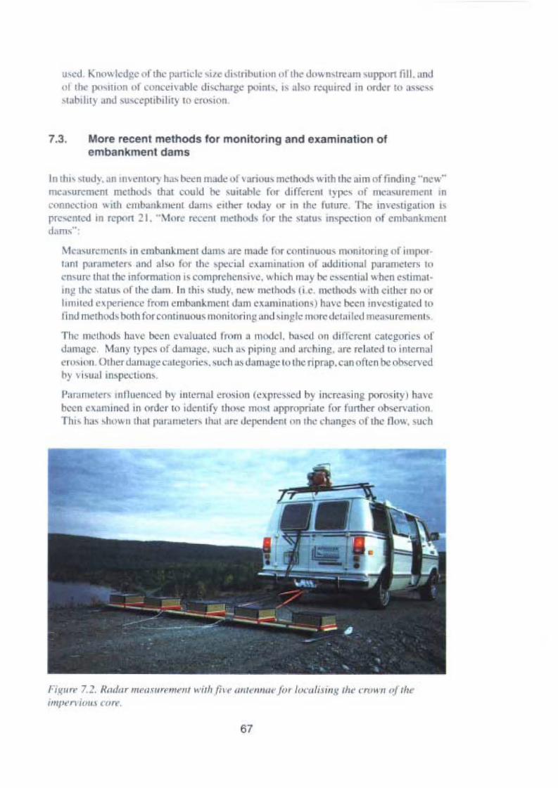
' ''~ I Knowlcdg n i the pantele ile Ji 'lIihull UII "I II • down trcarn upp"n fi l I. .mJu l III (1("nll'n u l conccivabl ui 'l'hal~c po in. " is al. n quirc m ordc r 10 ,I' ,
' l,loal ny ..nusu epub.li l ro en " 'l II
7.3. More recent melhods for moniloring lind oxamination ofembankmenl dams
In thl' 'lUJ) , an Im "ml'r) h..., been made uf vuriou-, mcthodvwith rh • im of indrng "ne w"mcasurcmcnt mcthodv thai could c ui tahlc fnr different 'YJlC' 01 ",C"'UI,,", ,' III In
conncc u n wuh "lIIbanLIII""t darn euber 'nd"y nr In the I UIIIIl' , 'I h mvcsupau on I '
pre 111.:0 III report ~ I. " M. r rceCIII IIIclh"J f.' r the ,Ialu m pccuon (If crnban '111, 111d. rnx" :
M asur -mcnn III cmbankment da ms are made I r conunuou« mnnnorinj! o illlP'"t.m t p.rramctcrv • nd al-,o I. r lite ' 1'C..: iaJ cvaminauon n i uddrnonal parumctcrs In
'n urr thnt thc III ormnuon ,\ centpreben ivc, which Illa ' be essenli..1wh n estimatIII)! the . t.nu , nrthe lam, In lh i, tudy, new merbods I i e. merbods With eirh '1 no ur11I1I1Il'tl cvpene n e from eml ankmcnt dam cxaminanuns ) huve been invc tigutcd In
lind method vboth to rc omluuousmonitorin ' "ud single lT1 lrc. k l.tilcd mcncuremcms
Th e me rheds ha ve bee n cvalua tcd fW ill :l nu...1 I. h,,'cc l o n d in .rem careporte 0 1
damagc . Many t~ pcs of tlalllagc . such as pipin ' . LTHI areh inf" l trl: 1~ I "r ('(l l o in temalCI"' " ' II.Ot he : d'lJ m.g~ c"I~l!uriC\ . suc h ,,-s dUIll"gc 10the n prap . ca n ottc n hc obscrvedhy vi ' u.1I inspccuun- ,
I':lronll te r- mlluenced h~ intcrnal eros ion (c~prcs.sc I hy in .rca sing porosity t haveb, n c xanu ued III " der 10 idenlif~ I hmc mo-a l.pprnpri;lJ ' or fun h r observat ionIhi hoL' 1lt.\\\'lI lh al p.uumeter-, thut are dependenr on the chnngcs 01 the 110w, uch
Fi ' .m · 7.~ . Hm/flr 1II"("'rt I'NIII'1l1 ...i lll {i, ,//I /C'Il/W" fO T lo, 'u/,,,i IlK rh.. emil" oft lu:impcr» lou» ('orf.
67

Single halemeasurement
- Transmitter
- Receiver
Transmitter ~ "
Cross hale measurement
Rocktyp A l.
Rocktyp B
Figure 7.3. Singel hole and cross hole measurement by nieans ofborehole radar accordlng to
Andersson et al (1992).
___ J
'. ,I s.:-~ - .,.•.
~
, ../1 \
,-,
/ - - - - - - -; ;... / / l" , . ,/, - -. /. \
-,
-;/.
\. '- .- ./ I
\ I .-=x--I, - - - -- --- / I I
X x x -, x x x X / X x I x x\ J
I ; I Ix x x - - - - - x I x /x x
\ fx \ x x x x x X / X I X x
\ /\ , / Ix x x x , / X x I x x x\
~x
/x x x X - - - - - -.r x x x X\ /
x X \ X/
-, x x x x X / X X X, /x x -, x x x X X / X X X
<, /
'il, /X X X X X X /
/x X X
Figure 7.4. Principle for electrical resistivity medsurement (modified jrom Rubinson andCoruh, 1988).
68

Temp °C20
18
16
14
12
10
8
6
4
2
Observation tubedownstream fromimpervious core--- Level: +65.2
Level: +64.7Level: +63.7
Level: +62.7Level: +61.7
Level: +60.7--- Level: +60.1
o I I ] I I I i I I , I
Oct Jan Apr Jul19881989
i I I I I I I I I l I i
Oct Jan Apr Jul1990
I i ~ [ I I j ,
Oct Jan Apr Jul1991
Figure 7.5. Temperature variations in a water leve' pipe at defined leve/s.
as hydraulic conductivity, are more sensitive than parameters dependent on changesof the soil rnatrix, for example density and resistivity. The evaluation model alsoincludes an assessment of accuracy and resolution. The methods have been dividedinto Non-Destructive Testing rnethods, Borehole methods and Other methods. Majorconc!usions regarding the most appropriate methods are summarised below.
Non-Destructive TestingGround-penetrating radar measures differences in electric conductivity or in radiowave velocity in the soil. These parameters depend on grain size and porosity. Thepotential for the method is examination, if possible by repeated measurements.
The resisti vitYin embankment dams is mainly dependent on water content. At presentresistivity measurements are quick but the accuracy is presently not so high. However.the method can be further developed.
Different rates of leakage water will cause anomalies in the self-potential along thedam. These variations can be used for leakage detection. Measurements of resistivityand self-potential are suitable bot h for regular monitoring and for more detailedexaminations of dams.
Borehole methodsThe basic principle for borehole radar and ground penetrating radar is the same. Byusing tomographic analyses on measurements between two boreholes, the accuracycan be increased. The method is appropriate for single examinations of dams.
The sonic cross-hole and the borehole radar methods use a similar technique, butinstead of analysing electromagnetic waves the Sonic Cross-Hole method analysessound waves. The methods are very much the same regarding accuracy and applications.
69
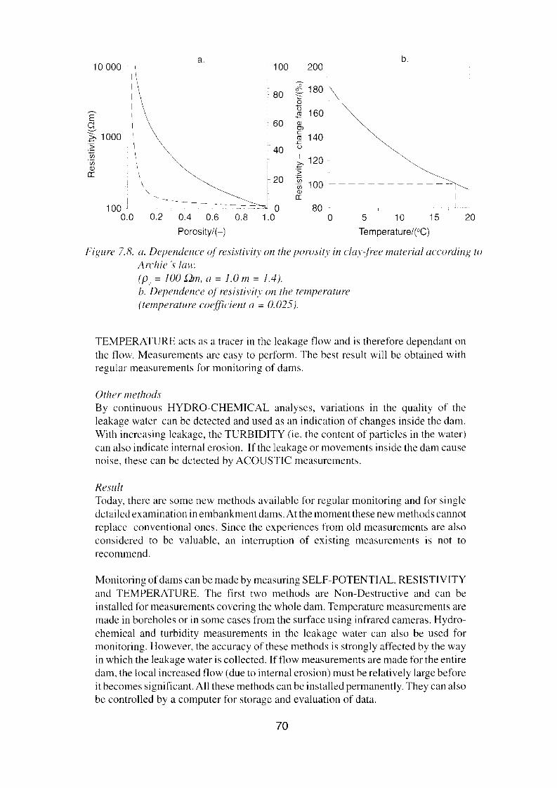
a. b.10000 100 200
80<fl. 180 \coo 160E J'l
c: 60 '"OJ
Z, 1000 c140t1l
s:> 40 o.~
~ 120(f) \<D 'ser: \ i 20 .~
\ i 'u; 100-, C '", er:
I -_._---...,.~80100 J O
0.0 0.2 0.4 0.6 0.8 1.0 O 5 10 15 20Porosity/(-) Ternperature/r-C]
Figure 7.8. a. Dependence ofresistivitv on the porosity in clav-jree material according to
Archie 's law.
(P, = 100 Dm, a =1.0 m = 1.4).b. Dependence o] resistivitv on the temperatu re(temperature cocfficient a = (J.(25).
TEMPERATURE acts as a tracer in the leakage flow and is therefore dependant onthe flow. Measurements are easy to perform. The best result will be obtained withregular measurements for monitoring of dams.
Other methodsBy continuous HYDRO-CHEMICAL analyses. varratrons in the quality of theleakage water can be dctected and used as an indication of changes inside the dam.With increasing Icakage, the TURBIDITY (ie. the content of particles in the water)can also indicate internai erosion. Ifthc leakage or movements inside the dam causenoise, these can be detected by ACOUSTIC measurements.
ResultToday, there are some new methods availablc for regular monitoring and for singledetailcd examination in embankment dams. At the moment these new methods cannotreplace conventionaI ones. Since the experiences from old measurements are alsoconsidered to be valuable, an interruption of existing measurements is not torecommend.
Monitoring of dams can be made by measuring SELF-POTENTIAL RESISTIVITYand TEMPERATURE. The first two methods are Non-Destructive and can beinstalled for measurements covering the whole dam. Temperature measurements aremade in boreholes or in some cases from the surface using infrared cameras. Hydrochemical and turbidity measurements in the leakage water can also be used formonitoring. However, the accuracy of these methods is strongly affected by the wayin which the leakage water is collected. Ifflow measurements are made for the entiredam, the local increased flow (due to internai erosion) must be relatively large beforeit becomes significant. All these methods can be installed permanently. They can alsobe controlled by a computer for storage and evaluation of data.
70

None of these new methods are generally recomrnended for examination of thecapacity to allow watcr level above reservoir water level. Howcver, georadarmeasurernents can be useful to identify scctions with low levels of the core crest.
The location of the leakage must be known before a detailed investigation. 'I'hus.quick and non-destructive methods such as SELF-POTENTIAL GEORADAR andRESISTIVITY measurcments are recornmended, dcspite little or no expericncc ofthe methods in Sweden. After localization of the leakage, more detailed measurements can be made using boreholc rnethods, such as BOREHOLE RADAR andSONIC CROSS-HOLE measurements. In many cascs TEMPERATURE measurements can be usefu!.
The investigation summarises and compares the suitability of more recent methods fordifferent purposes in the present situation and for the typcs of darnage that may occur inernbankment dams, and also comments on the potential of the methods for dcvclopment.
In connection with the above, pilot projects have been conducted for several differentmethods, narnely one project that aims at determining where the seepage comes from bymeans of isotopic analysis of the water and two projects which aim at detecting deviationsin the water tlows in dams by means of electrical methods.
7.4. Isotopic analysis of seepage from dams
The project aims at testing a method in order to determine whether the water founddownstream from a dam is seepage from the reservoir or local runoff from the downstrearnside of the dam. The investigation is presented in report 22, "Isotopic analys is of seepagefrom dams":
Analyses of the stable isotope oxygen-IS were uscd to determine if water, founddownstream from a reservoir, was seepage or local runoff generated from an areadownstream from the dam. The concentration of the stable isotope was analysed insamples from the reservoir, the groundwater and also the suspected seepage. Thereservoir level, the seepage hydrograph and precipitation were also analysed to studytheir interaction. The method was applied to the Grundsjö dam in the River Ljusnanand the Flåsjö dam in the River Ljungan. It was shown that the water founddownstrearn of the Flåsjö dam probably origmates from the reservoir, while thesuspected leakage at the Grundsjö dam is probably locally generared runoff downstream of the dam.
An assessment of the potentialoffered by the rnethod, however, is that the results of the pilottests were not entirely unanimous and that a certain amount of support must be accepted inorder to verify the interpretation. Furthermore, the isotope analysis has to be carried out inthe laboratory, which exeludes methods in those cases where an automatie monitoring isrequired.
71

7.5. Monitoring of the impervious core by measuringthe self-potential and resistivity
The project is presented in report 23, "Monitoring the function of the impervious core bymeasuring the self-potential and resistivity'':
InternaI erosion in embankment dams is a common cause of dam failures. The use ofgeophysics in the mapping of electrical phenomena and also the monitoring ofchanges in parameters addressing geo-electrical methods is considered to be atechnique with high potential for detecting inhomogeneities at the dam core whichmay later lead to fatal internai erosion.
A project was started in 1992 with the principal aim of devcloping a prototype for adam monitoring system based on frequent measurements at many point s of theapparent resistivity and self-potential of a dam.
I PEGE~HUSE:T
(Water level gauge area)
Figure 7.6. Basic diagram ofmeasurement system.
The system was developed and installed in the Suorva dam in 1993, where measurements have been carried out since August 1993.
The system performs these measurements automatically. Communication with thesystem is maintained via modem. For example this allows the remote setting ofparameters for data acquisition as well as remote error diagnosis.
In general, the data quality has been satisfaotory. During the period with unfrozenground (May-October) the data quality has been very good. However, frozen groundduring the winter has prevented the injection of a current strong enough to maintaingood signal to noise ratios, hampering effective resistivity surveys.
72

Plastie bueket
Coneetion box = intelligent relay.Cable
"~-o • ~-,""'-.::r--'_._
:~~-_.~~i (. ,.,' _.' ~ \~:~-:;~)~~::.i .Insulation
Surfacem"'d~~!?{f;t;~~~~ ~i~~~f;>;;of the dam- o.oo,'.o>'~;/)4.ooo):'i.toooL~-~l~ o"'~~J~0-,"t;/4i'i'oo.oi
/ '~.- /
moraln, Potential eleetrode
Figure 7.7. Basic mode! of electrode installation.
Self-potential measurements show that a streaming potential is developed within thedam, thus enabling studies of the homogeneity in seepage and changes in zetapotential with time.
The results indicate four (possibly five) sections in the dam where anomalousbehaviour in the self-potential is recognised and interpreted as inhornogeneousseepage.
The resistivity data from this dam are difficult to interpret as several different sources forresistivity variations probably interact. The problems are emphasised due to lack ofresistivity monitoring of a closed cycle in water levels where there is a hiatus of 10m.
The results of the self-potential measurements appear to be particularly promising. In thefollowing related project, a study has been made which includes, among other things, thecffect of temperature on resistivity reaction.
7.6. Monitoring of the impervious core by analysingvariations in resistivity
The project is presented in report 24,"Monitoring of the function of the impervious core byanalysing variations in resistivity":
International experience has shown that there is a need of developing methods andmethodology for seepage monitoring in embankment dams, which is the backgroundand motive for this project. Of particuIar interest are methods able to register smallseepage changes in the dam, i.e. in an early stage before internaI erosion starts to affectthe security of the dam.
73

----------------------
Since temperature affccts the resistivity, the basic hypothesis orthis project is that theseasonal resistivity variation, as well as the temperature variation, can be used fordeteeting increased seepage. The aim is also to atternpt to quantify the water tlow bystudying the resistivity variation and further develop the interpretation methodologydeveloped for temperature measurernents.
The data aequisition system uscd is computer controlled and includes a rcsisiivitymeter. a switch box and multi-core cables, In this application mensurements arecarried out by using permanently iristalled electrodes, which each time are connectedto the multi-core cables, The clectrodes consist of stainless steel plates buried inshallow pits which were back-filled with fine-grained material. Only a cable end isvisible at each elcetrode arter the back-fill.
Resistivity measurernents were earried out in the ernbankment dams at Lövön andMoforsen with approximately two months interva!. In total. eight measurernents wereearried out at Lövön and six at Motorsen. Wenner configuration was uscd both alLövön and Motorsen. In addition, pole-pole configuration was used at Moforsen toinerease the depth penetration on the relatively short dam.
Qualitative interpretation of resistivity data was made by plotting data in pseudoseetioris. Quantitative interpretation was carried out by using two-dimcnsionalnumerical inversion, where the software autornatically adjusts the interpreted modelresistivities to fit the field data.
The quantitative interpretation of water flow through the dam is based on the Iact thata variation in resistivity in the reservoir watcr will propagate into the dam with theseepage water, The variation due to variations in ion content will travel with porevelecity. whereas the variation due to temperature will move with the thermalveloeity. The time variation in the resistivity in the dam can be mortitored by meansof repeated resistivity measurernents.
The simplest way of evaluating consists ofcomparing extreme values ror the absoluteresistivity in the reservoir and the interpreted resistivity in the ernbankment dam. Thediagrams are used to calculate phase shifts for the highest and lowest values,
Evaluation of the amplitude can be made on the assurnption that observed resistivityvariations in the ernbankment dam emanates from the temperature variation in thereservoir, The attenuation thus arising can be attributed primarily to heat conductionperpendicularto the flow direction. An independent evaluation can thus be made withthe two methods. which allows some controi of the result.
The measurernents from Lövön showa significant variation along the profile. TheWenner measurements gave very stable results. Comparisons with temperaturerneasurements were made in one section in a standpipe located in the filter downstream. Evaluation of the resistivity data aceording to the amplitude method gaveapproximately the same result as the phase shift method. However. the temperaturemeasurements gave a higher llow concentrated to a smaller zone, whereas the resultscorrelate better at depth. The ditferences are reasonable considering the highervertical resolution of the temperature data compared to the resistivity data.
74

The rcsistivity mensurements at Motorsen wcrc earried out along three lines: alongthe dam crest and the two tcrraccs. The variation in measurcd data is smaller than forl.övön, but the interpretation resulted in significant variations with time. The polepole configuration gives alarger depth penetration than Wcnner, but poorer verticalresolution. In addition, pole-pole data is more susceptible to noise, duc to the longreferencc cables.
At Molorsen temperature mcusuremcnts were carried out in three standpipes. wherethe result can be used for comparison betwecn the methods. EvaIuation of thercsistivity mcasurernents gavc results in rather good accordance with the temperaturemensurements.
SP-measuremcnts at Lövön gave stable results, with a small variation. However, atMo-forsen the SP-result is considered unreliable.
In conclusion. the water see page can be detccted and to some extent quantified by theinterpretation of resistivity data. The method can be further improved in all parts ofthe system, as in installations, resistivity interpretation, seepage evaluation andpresentation of results. By using new numerical models. the inlluence of 3D-effectsand other various sources of disturbance can also be assessed.
At present the method is most suitable for longer dams. Both measurement andinterpretation are rnore complicated for short and high dams, and a differentrncthodology necds to be used. Thus there is a need for lurther developrnent for suchdams. The potentially low detection levels me an a possihility of detecting internaIerosion at an earl y stage. Since the rnethod is non-destructi ve the development in timecan also be monitored.
The rnethod appears to be prornising for the rnonitoring of'dams, particularly in combinationwith temperature measurernents.
75

76
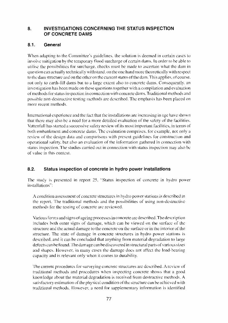
8. INVESTIGATIONS CONCERNING THE STATUS INSPECTIONOF CONCRETE DAMS
8.1. General
When adapting to the Committces guidefines. the solution is deemed in certain cases toinvolve mitigation by the temporary flood surcharge of certain dams, In order to be able toutilise the possibilities for surcharge. checks must be made to ascertain what the dam inquestion can actually technically withstand. on the one hand more theoretically with respectto the dam structure and on the other on the current status of the dam. This applies, ofcourse.not only to earth-fil] dams but to a large extent also to eoneretc dams. Conscquently, aninvestigation has been made on these questions together with a compilation and evaluationofrnethods for status inspection in connection with concrete dams. Traditional methods andpossible non-destructive testing methods are described. The emphasis has been placed onmore recent methods.
International expericnce and the fact that the installations are increasing in age have shownthat there mayaIso be a need for a more detailed evaluation of the safety of the facilities.Vattenfall has started a successive safety review of its most important facilities, in tenns ofboth embankment and eoneretc dams. The evaluation cornprises, for exarnple, not only areview of the design data and comparisons with present guidelines for construction andoperational safety, but also an evaluation of the information gathered in connection withstatus inspection. The studies carried out in connection with status inspection may also beof value in this context.
8.2. Status inspection of concrete in hydro power installations
The study is presented in report 25. "Status inspection of concrete in hydro powerinstallations":
A condition assessment of concrete structures in hydro power stations is described inthe report. The traditional methods and the possibilities of using non-destructivemethods for the testing of concrete are reviewed.
Various forms and signs ofageing processcs in concrete are described. The descriptionincludes both outer signs of darnage, which can be viewed on the surface of thestructure and the actual damage to the concrete on the surface or in the interior of thestructure. The state of damage in concrete structures in hydro power stations isdescribed, and it can be concluded that anything from material degradation to largedcfects can be found. The damage can be discovered in structural parts of various sizesand shapes. However, in many cases the damage doc s not affect the load-bearingcapacity and is relevant only when it comes to durability.
The current procedures for surveying concrete structures are described. A review oftraditional methods and procedures when inspecting concrete shows that a goodknowledge about the material degradation is received from destructive methods. Asatisfactory estimation of the physical condition ofthc structure can be achieved withtraditional methods. However, a need for supplementary information is identified
77
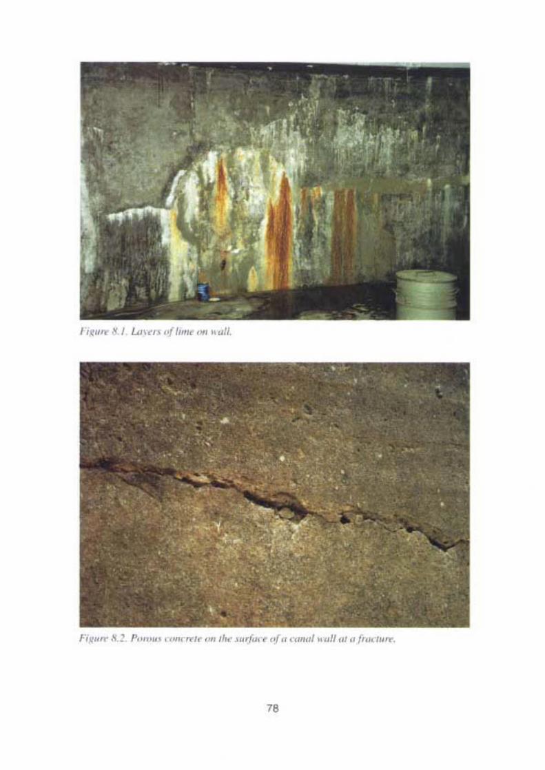
"
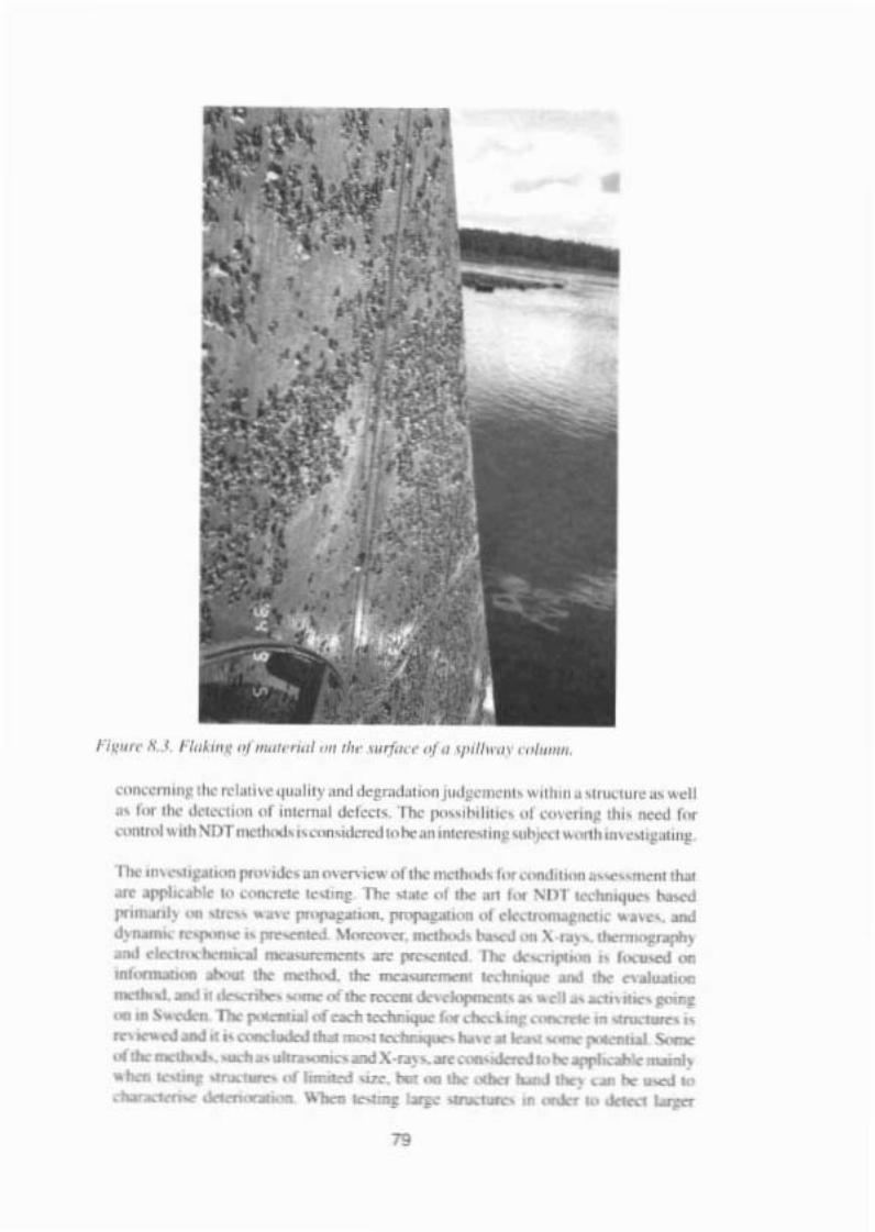
" '"' , "" 01" . .....1," ...,o ol<'c......."'"jUd~....."" ~ ,'h.., • ~ ',...,u," .. • • 11.. I". , dn ,.'" ,( ,""'.....1ol<l'"<l' Il., I'~" "'I" ",, .~ ,,~<'On. 'h.. _ h., S IJT........ I-,,,'''',.I<..,..,, .... .. ,.........,.. """"" .....hm...." ..'''l!
110< '"" , "".. ..., "'."'..,.. '" ,h< ma I,." ' ....... ,"'"'"" arf'l>< '" «__ .., TIo< ...... ,( I •• , 1> 1' -,...._
1"'_) '. """ ~ ""'I"F. .... ""..- "' _'" •••~ -'~_ .....,.- \-"._.J<~ \ ..)...... , ' )aM _'"'__ lO<.....,.- ,... "' .-",._ ,. 1,._ ...'""--- 110< """".L "'" " ~ -' __ _-_<#""' "" , , -....S_ 110:"....-"'_ : ""._ _, .."" _1 1 •__ 4 _ .._I"-.I~_<# _ __ __._\ .r~ .._'_ i4 ~._----..__........-.-...., ..--"k"'_ ..__ loiJ< _ .-. • .-. '" -. l.oJI<r

Jcfn-'s_ II c. I"",I, 1",_",J uII e lect rom.rgne tic ".I\'cs and h", frequen ) stcc" " .1\ c, cun
h • II'C'J.
The rn"'t"thm" h.I'c,I ..n 'OT." hrch an be uved f....r evalu.uing the rencral s,..te " fu vt ru tun: . •m; di'clIs cd uch an l S'iC"nJ n i of the g e l roll ' tal "n m. I ' on theh."I' ..f In.:al dciccuon nf de fect u mg fnr e ample srre v wuve -hoc, nr r.1brech..,.. , '\ nnlhe'l,u"lhi h.~ i, 'uu", an auuunnted restin •p ",..dure v urh as "':.111 mil '
"-i,~II"" .J, ·lIm"li tlf./ witl) II ,"', ' drit t gi""\ an id<'IJ I) //Je 'tJlII rrtr III thr strnrture.
BO
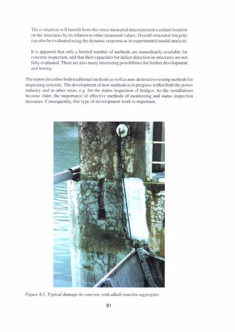
r > cv.iluuuun will benefi t Irnm thtvSin c rncnsurcd dm" reprosent a ccrtam locauonon the -tructure- ho ' il' relauon In other m casurcd value-, Overull -trurtural i rll ~~ril }
can a lso I~ cvaluuted u,ing rh dyna nn response a, in C! perimenral modul anal i.
II " "rp.Jrenl Ihl l onI)' .1 lim" Ii number of methods ur • inllllt.''I.l ialcl) a' arlahle fn rc.. neretc mspecuon, and Ih:ll thcir ca p: II1C' l r dc tcct dciection in strucrurev are notfull} C!' alu ated, There are "I ..., man)' ini :f,' slin!! po sihi lll.C' lo / funher deveh pmenl.1IIJ te sun..l .
The report devcribe-,both IraJi lioo.llllle lh v ; 'weil OI-s 11011 ..strucu ve lC,U II" Il lClho d , forin'l CIIn!! conc 'le , I'he d'" lopmc nt 01new m thods is in progrc" .... ithin borh the pnwerinJu'll) und in other are.iv, e.g fo r II • srarus inspectiou uf bridp ·s. A. the in. lalbl illllber. une older, the importart 'C 01.:1 ccuvc mcthods ot monno nng and '1.IIU' invpectionincrcas l , Conscqucmly. Ihis typc of d -velopmem Vo·(lrJ.. Ls importunr.
Figur 8.5. Typical damagc ir, concret« 11 irir alkall-rra rtiv« 1IJ: ·"'.liar".
81

82
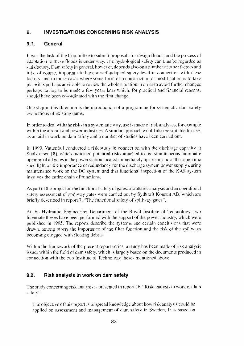
9. INVESTIGATIONS CONCERNING RISK ANALYSIS
9.1. General
It was the task of the Committee to submit proposals for design floods, and the process ofadaptation to these floods is under way. The hydrological safety can thus be regarded assatisfactory. Dam safcty in general. however, depends also on a number of other factors andit is. of course, important to have a well-adapted safcty level in connection with thesefäetors. and in those cases where sorne fonn of reconstruction or modification is to takeplace il is perhaps advisable to review the whole situation in order to avoid lurther changesperhaps having to be made a few years later which, for practical and finaneial reasons.should have been co-ordinated with the first change.
One step in this direction is the introduction of a programme for systematic dam safetyevaluatrons of existing dams.
In order to deal with the risks in a systematic way, use is made of risk analyses. for examplewithin the aircraft and power industries. A similar approach would also be suitable for usc,as an aid in work on dam safety and a number of studies have been carried out.
In 1990, Vattenfall conducted a risk study in connection with the discharge capacity atStadsforsen [8], which indicated potential risks attached to the simultaneous automaticopening of all gates in the power station located immediately upstream and at the same timeshed light on the irnportance of redundancy for the discharge system power supply duringmaintenance work on the DC systern and that functional inspcction of the KAS systeminvolves the entire chain of functions.
As part ofthe project on the functional safety ofgates, a fault tree analysis and an operaticmalsafety assessment of spillway gates were carried out hy Sydkraft Konsult AB, which arebriefly described in report 7, "The functional safety of spillway gates",
At the Hydraulic Engineering Department of the Royal Institute of Technology, twolicentiate theses have been performed with the support of the power industry, which werepublished in 1995. The reports describe the systems and certain conclusions that weredrawn, among others the importance of the filter function and the risk of the spillwaysbecoming clogged with tloating debris.
Within the framework of the present report series, a study has been made of risk analysisissues within the field of dam safety, which is largely based on the documents produced inconnection with the two Institute of Technology the ses mentioned above.
9.2. Risk analysis in work on dam safety
The study concerning risk analysis is presented in report 26, "Risk analysis in work on damsafety":
The objective of this report is to spread knowledge about how risk analysis could beapplied on assessment and management of dam safety in Sweden. Il is based on
83
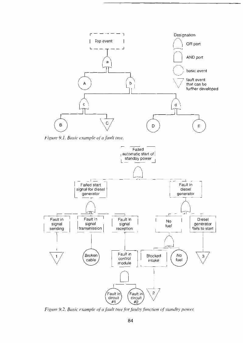
fault eventthat can befurther developed
r-----,
I Top event
Designatian
O OR port
O AND port
O basic event
\7
Figure 9.1. Basic example ofafault tree.
Dieselgenerator
~ils to start
Nofuel
Blockedintake
Fault incontroimodule
Fault insignal
reception
I Failedautomatic start of
standby power
Fault insignal
transmission
Failed startsignal for diesel
generator
Fault insignal
sending
Figure 9.2. Basic example ojajault treejorfaulryfunction of standbv powet:
84
international experience of risk analysis of dam installations, and describes thepUI'pose, possibilities and principal steps of the methodology.
Of about 900 hydropower dams currently existing in Sweden, 143 are classified ashigh dams (i.e. dam height over 15 m). This dam population is ageing, placing moreand more ernphasis on the need for maintaining proper safety at these installations.Although dam failures are infrcqucnt, the consequences of a single failure may besevere and should by all practical rneans be avoided. It is imperative that the risksplaced on society by these structures are systematically evaluated and assessed interms of improving overall safcty and minimising the impacts of possible failure. Inthis. risk analysis can be an effieient tool.
The use of risk analysis is weil ostablished in performing safety assessment analysesof many different technical systems, but has only to a limited extcnt been uscd for theassessment of dam safety in Sweden. Since the 1970s researchers in several eountrieshave tried to make risk analysis an effeetive means of dam safety evaluation. In recentyears the work has been intensified. and today risk analysis is actively being used inthis field.
Risk analysis is defined as any number of means or methods to identify and evaluaterisks. Simply put, risk analysis for the assessmentofdam safety involves identificationof all series of events that may cause dam Iailure, estimation of the probability of the seevents. the eonsequenees eaused by thern, and cvaluation of the effeet of remediaImeasures. The objeetive of a risk analysis safety assessment of a dam installation isto identify the major eontributing risk factors of the system and cvaluate how the y maybe minimised in an effective way, Ultirnately, the aim is to reduce the residual risk toan acceptable levcl.
The purpose is not to determine an absolute measure ofthe safety of a dam installation.The real utility of the approach lies in assessing dam safety on a relative basis. Thatis, when one has determined the risk at a certain dam, one should evaluate the effectsof alternative risk reducing measures.
A proper start-up of a risk analysis is a workshop where a projeet group, eonsisting ofexperts in all relevant areas, screens failure modes and derives failure probabilities.An appropriate application of risk analysis for Swedish eonditions would best beaccornplished by the use of both event trees and fault trees, Event trees can be usedto analyse complete sequenees of dam failure, whereas the analysis of sub-systems isbetter suited to fault tree analyxis.
Today, the use of expertjudgement for estimation of failure probabilities is essential.This is, among other things, due to the fact that the available documentation of daminstallations and the database on historical incidents is commonly insufficient. Theestablishment of an adequate system for the reporting of incident data would be ofconsiderable benefit for future risk analyses.
Risk analysis safety assessments are heavily dependent on the quality of the availabledata. Throughout the analysts all assumptions and reasoning. and the documentationthey are based upon, should be carefully documented. This cnables future up-dating
85
or the analysis. ror cxample if lurther documentation and data becornes available orif the level or detail should be increased.
Risk analysts is decmed to be a valuabIe tooI in connection with dam safety, primarily inorder to give insight into where the wcakest links are to be found and how resources for damsafety can best be apportioncd. The method, which so far has only been tested to a limitedextern in this country, is attracting considetable attention and can be expccted to be used alot morc in the Iuture. This is one ofthe areas being given priori ty by the power industry forcontinued development work. Work is in progress within the industry on introducing acommon system for incident reporting. which is expccted to give better input for Iuturc riskanalyses.
9.3. Incident reporting
The feedback of expcrience from evcnts and incidents that have taken place is an extrernelyvaluable way of increasing safcty. During the developrnent of the power industry, theemphasis lay on transferring experiencc within the design and construction areas. and howsystematic this process was varics from company to company and probably also in time.
During the operatiorull stage there has also been a feedback of experience, which can beillustrated by several of the reports in the series. However, it has not been systematic in theoperational stage, which means that a considerable amount of data on safety is missing.
Other areas have had effective systems of incident reporting for many years, particularly thenuclear power and aircraft industries, and experience from this has been extremely good.
As a step in the work on improving the safety, a system ofincident reporting shouId thereforebe introduced within the dam safety area, and in order to make it as effective as possible itshould be adopted for common use throughout the hydropower sector. It is of course aIsoimportant for the system to be uscd in order to reach conc!usions and spread information onthem. In report 7 "The functional safety of spillway gatcs", it was also proposed that thesystem for incident reporting should be improved by establishing routines for circulationwithin the power industry, which could lead to improved designs and safety procedures. Theinternational exchange of experience with in the field of dam safety is aIso of significantvalue in this context. A comparison can be made with en-operation within the nuclear powerarea between different owners concerning the registration and proeossing of componentfaults.
Work is at present in progress within the RIDAS project on developing a common incidentreporting system for the hydropower area. During Spring 1997, work started on the testingof a proposal for a reporting system at a certain number ofplants and the intention is, as soonas certain adjustments have been made, to apply the system within the entire hydro powerseeter.
86

10. RESEARCH AND DEVELOPMENT WITHIN THE FIELDOF DAM SAFETY
The power industry has in recent years conducted extremely active research and developmentwork within the field of dam safety through the Association of Swedish Water RegulationEnterprises, VASO and the power industry s organisation for energy-related research,ELFORSK. The present series of reports is an example of this. The research within the areahas also been supported by both project assignments and more general support to, above all,the Department of Hydraulic Engineering at the Royal Institute ofTechnology, Stockholmbut also to the Institutes of Technology in Luleå (now Luleå University) and Lund.
This has meant that the universitieslinstitutes have in recent years been able to run doctorateand licentiate courses closely connected with dam safety issues, some of which have beencompleted.
Among the development projects carried out, mention can be made of methods for the statusinspection of dams, in which the results of certain projects have been so good that themethods have been used for the investigation of sinkholes at the Bennett Dam in Canada,which is one of the largest embankment dams in the world.
In addition to recommendations and what is otherwise stated in reports included in thisseries, there is good reason to continue working on questions such as organisation, manmachine interfaces, preparedness and a continued investment in research and developmentefforts both nationally and internationally within both traditional dam safety issues and inconnection with those mentioned above.
87

88
11. CONCLUSIONS AND RECOMMENDATIONS
The consequence classification and dimensioning guidelines proposed by the Committeefor Design Flood Determination (the Committee) involves a significant tightening of therequirements for Consequence Class I dams with respect to design tlood. A dam failure canhave serious consequences. and the principal responsibility for the safety of a dam rests withthe owners.
Whcn they were issued in 1989, the Committee's guidelines were regarded by man y asinvolving exceptionally high flows, but as calculations were successively completed fordifferent rivers, and following the experience gained in connection with floods thatoccurred in Sweden in both 1993 and 1995 coupled with the heavy flooding that took placein Norway and Germany in 1995 and later, this view has changed and thcre has been ageneral acceptance of the level applied in the guidelines.
In addition to the recommendations and the other statements made in the reports inc!udedin this series, therc is every reason to continue working on questions such as organisation,man-machine interfaces and preparedness, and to make further research and developmentefforts both nationally and intemationally on traditional questions connected with damsafety as weil as on those specified above. This work has already started.
It is important that the work which has already started on adaptation to the Committee 'sguidelines should be carried out in a responsible and competent way, and suitable that in thiscontext an extensive overview should be made of the safety level so that the increase in thedam safety Icvel aimed at in the Comrnittee's work will really be achieved, even wherefactors other than high floods involve significant risk factors. This could, for exarnple,concern the design ofthe dam or its current status. It is particularly important, of course, thatconsideration be given to other similar factors in time where rebuilding is to be carried outso that major resources are not wasted without achieving the required increase in safetylevel, Risk analysis is deemed to be a valuable tool in work connected with dam safety,inC!uding this particular aspect.
An incident reporting system is judged to give the preconditions necessary to continueworking systematically on finding ways of improving dam safety. A system of this kind isat present being devcloped for the purpose of dam safety.
In certain cases, there may be uncertainty concerning the effects of certain factors. Shouldthis be so, sensitivity analysis is recommended in order to shed further light on the matter.Consideration can be given to uncertainty regarding the real discharge capacity of aspillway. for exarnplc, by analysing which water levels in the reservoir will be theconsequence of different assumptions. If there is considerable uncertainty, whereverpossible testing should be carried out. A systematic way of analysing and evaluating thesafety of existing dams is the so-called SEED analysis (Safety Evaluation of ExistingDams), which has been developed by the Bureau of Rec!amation and is applied in the USAand various other parts of the world. Similar detailed evaluations of dam safety have beencarricd out for a number of dams in Sweden and are recommended in the power sectorguidelines for dam safety, RIDAS.
During the adaptation or compliance process for existing dams, it is also important to
89

carefully review conceivable occurrences and thus learn the way the system functions whileat the same time acquiring a mental preparedness for entirely unanticipated combinationsof events in connection with high floods. For this reason. it is also important for personnelwith positions of responsibility for the rivers to take part in or follow the work. It is alsoimportant to clarify instructions and areas of authority so that the measures assumed inconnection with the dimensioning work are really adopted if the need arises. The sameapplies to agreements between different companies, which in a critical situation must cooperate in an effective way. It is also important for attention to be given to questionsconceming dam safety, for example in connection with the increased use of contractors orwhere the manning situation changes, which may have an influence on call-out responsetimes and thereby mean that the need for and demands on the reliability of systems forautomatic monitoring and control increase in connection, for example, with spillway gates.
90

12. REFERENCES
12.1. Survey and Development Projects related tothe new Swedish Guidelines for Design Flood Determination
1. HuvudrapportMain report. see 2Malte Cedersträm. vattenfall AB
2. Main report (this report)Malte Cedcrstrom, vattenfall AB
3. Dimensionerande sektioner i vattendragLimiting sections in watercoursesKarl Ryl/ers. VBB Anläggning AB. SWECO
4. Skred i niporLandslides in river bluffsRolf Christiansson, vattenfall Hydropowcr ABErik Ane't; Vattentall Hydropower AB
5. Verklig avbördningskapacitetReal spillwav discharge capacitvNils Johansson, Vauenfall Utveckling ABKarl Ryt/ers. VBB Anläggning AB, SWECO
6. Drivgods vid dammarFloating debris in damsNils Johansson. vattenfall Utveckling AB
7. Utskovsluckors funktionssäkerhetFunctional reliability ofspillway gatesStefan Lagerholm. Svdkraft Konsult ABBengt Lundh. Svdkraft Konsult AB. et al
8. Fuseplug som kompletterande utskov vid befintliga svenska dammarFuse-plug as auxiliary spillway at existing Swedish damsMichaela Dan, Royal Institute of Technologv, Stockholm
9. Flödesdämpning vid svenska dammarFlood mitigation in Swedish damsKarl Ryl/ers, VBB Anläggning AB, SWECOJohn-Edvin Sandell, vattenfall AB
10. Vågor i vattenkraftmagasinWaves in hydropower reservairsKlas Cederwall. Royal Institute of Technology, StockholmHans Bergh, Royal Institute ofTechnology, Stockholm
91

11. Erosionsskydd för fyllningsdammars uppströmsslänterErosion proteetlon of upstream shoulders ofcmhankment damsKenneth Burstedt. Båkab Energi ABRov Nilsson, Vattenfall Hydropower ABSven-Erik Paulsson. VBB Anläggning AB, SWECO
12. Fyllningsdammars förmåga att tåla överspolande vågorThe capacity ofembankment dams to resist overtopping wavesÅke Nilsson, VBB Anläggning AB, SWECOPer Vallandel; VBB Anliiggning AB, SWECO
13. Filter - inventering och funktionsanalysFilters - inventorv andfunctional analvsisÅke Nilsson, VBB Anliiggning AB, SWECO
14. Geomekaniska filter och erosion i tätkärnans krönGeomechanicalfilters and erosion in the crest ofthe impervious coreAnders Wörman, Uppsala UniversityOlivier Blanc, Chalmers University
15. Fyl1ningsdammars förmåga att tåla överdämningFlood surcharge capocity of emhankment damsÅke Nilsson, VBB Anläggning AB, SWECORoy Nilsson, Vattenfall Hydropower AB
16. Åldersförändringar ifyllningsdammarAgeing of embankmcnt damsÅke Nilsson, VBB Anläggning AB, SWECO
17. Stenfyllningsdammars stabilitet vid genomströmningThe stability ojrockfill dams during overflowing ofthe core@ivind Solvik, Norway
18. Metoder för dammbrottsberäkningarMethodsfor dam break calculationsNils Johansson, vattenfall Utveckling AB
19. Betongdammars förmåga att tåla överströmningThe capacity ofconcrete dams to withstand overtoppingGeorg Andersson, Vattenfall ABBengt Forsberg, Vattenfall Hydropower AB
20. Beprövade metoder för tillståndskontroll av fyllningsdammarEstablished methods for monitoring and examination ofcmbankmcnt damsÅke Nilsson, VBB Anläggning AB, SWECO
92

21. Nyare metoder för tillståndskontroll av fyllningsdammarMore recent methods for the status inspection ofembankment damsSam Johansson, J& W Anläggning ABMaria Bartsch, J& W Anläggning ABOla Landin. J& W Anläggning ABGerhard Barmen, Lund UniversityThorleif Dahlin, Lund UniversityPeter Ulriksen. Lund University
22. Isotopanalys av läckvatten från dammarlsotopic analysis o/ seepage [rom damsKatarina Losjä. SMHISten Bergström, SMHI
23. Övervakning av tätkärnans funktion genom mätning av självpotentialoch resistivitetMonitoring the function ofthe impervious core bv measuring the self-potential andresistivityCarl-Axel Triumf Triunipli Geophysics ABHans Thunehcd, Luleå UniversityArne Enstrom; Luleå University
24. Övervakning av tätkärnans funktion genom analys av resistivitetsvariationerMonitoring ofthefunction ojthe impervious core by analysing variations inresistivitvSam Johansson, HydroResearchThorleif Dahlin, Lund University
25. Tillståndskontroll av betong i vattenkraftanläggningarStatus inspection oj" concrete in hvdropower installationsUlrika Wiberg, vattenjall Utveckling AB
26. Riskanalys i dammsäkerhetsarbetetRisk analvsis in work on dam safetvMaria Bartsch. Roval Institute of Technology. Stockholm
93

12.2. Other references
l. Riktlinjer för bestämning av dimensionerande flöden fördammanläggningar.Slutrapport från Flödeskornmitten. Starens Vattenfallsverk, Svenska Kraftverksföreningen, Sveriges Meteorologiska och Hydrologiska Institut 1990.(Guidelinesjor designflood determination)
2. Vattenlagen.(Water riglas act.)
3. Jord- och stenfyllningsdammar. Vattenfall \988.(Earth and rockfill dams.)
4. Fångdammar - ras och tillbud vid svenska vattenkraftverk.Vattenfall V 1991/27.(Cojferdams - dambreaks and incidents at Swedish hydropower plants.i
5. Ökad avbördningsförmåga i befintliga dammar. VASTlVattenfal1.(lncreased discharge capocity in existing dams.)
6. Älvsäkerhet. SOV 1995AO.(Safety during high floods and dam safety.)
7. RäddningstjänstIagen (~43). Meddelande från Räddningsverket 1994:2(Rulesfrom the Swedish rescue agency.)
8. Riskstudie över avbördningssystemet i Stadsforsen. Vattenfall U I 990! 34.(Risk study on the spillwa» system in Stadsforsen. )
9. Hydropower '97. E. Broch & D. K. Lysne, N. Flatabl'l, E. Helland-Hansen.A. A. BalkemafRotterdam/Brookfield 1997.
10. RIDAS - kraftföretagens riktlinjer för dammsäkerhet.Svenska Kraftverksföreningen \997.(RIDAS - the Swedish Power Association guidelinesfor dam safety.)
11. Hävertutskov för fyllningsdammar. KTH, Vattenbyggnad, report no 39, 1988.(Using siphon spillway to increase the discharge capacity.]
For references given in extracts from reports, see the report.
94

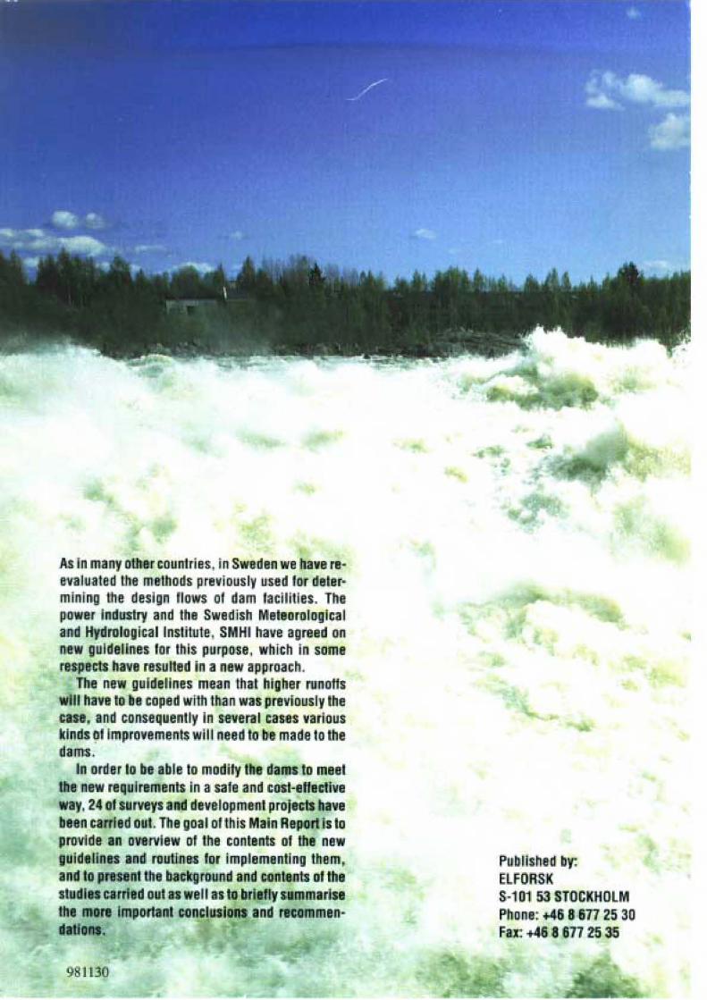
AsInmany other eounlrles, inSWBdenwe have rellvaluatBd Ihe melhods prevlously used for deler·mlnlng Ihe design 1I 0ws of dam lacilltles. Thepower Industry and the Swedish Meleorologlcaland Hydrologlcal (nslitute, SMHI have agreed onnew guidelInes lor thls purpcse, which in samerespests have resul1ed Ina new approach.
The new guIde lines mean thai hlgher runoflswill have lobe coped wilh thanwas prevloLlsly Iheease, and consequenll~ In several cases varlouskindsol lmprovements will nesd tobe made toIhedams.
In order lo be ableto modity Ihe dams to meelthe n wrequiremenls In asal and cosl·eflecli veway, 2401 surveys and dBvelopmen1 proj cls havebeen tarrledoul.The goal 01 Ihis MalnReport Isloprovlde an overvlew 01 Ihe conlents of Ihe newguide lines and roullnBl for implementing Ihem,and lo presenl the background and conlenls ollhesIudiescarrled oulasweil as tobrieflys mmarlseIhe more Importanl concluslons and recommen·dal/ollS.
9 1130
Pub llshed by:ELf ORSKS-101 53 STOCKHOLMPhone: +46 8 677 25 30far. +46 8 677 2535
Copyright © 2022 FDOKUMEN