Liquid water transport in a mixed-wet gas diffusion layer of a polymer electrolyte fuel cell
11
Chemical Engineering Science 63 (2008) 1081 – 1091 www.elsevier.com/locate/ces Liquid water transport in a mixed-wet gas diffusion layer of a polymer electrolyte fuel cell Puneet K. Sinha, Chao-Yang Wang ∗ Electrochemical Engine Center (ECEC), and Department of Mechanical and Nuclear Engineering, The Pennsylvania State University, University Park, PA 16802, USA Received 13 August 2007; received in revised form 30 October 2007; accepted 4 November 2007 Available online 13 November 2007 Abstract After PTFE treatment, a gas diffusion layer (GDL) of a polymer electrolyte fuel cell (PEFC) features mixed wettability, which substantially impacts liquid water transport and associated mass transport losses. A pore-network model is developed in this work to delineate the effect of GDL wettability distribution on pore-scale liquid water transport in a GDL under fuel cell operating conditions. It is found that in a mixed- wet GDL liquid water preferentially flows through connected GDL hydrophilic network, and thereby suppresses the finger-like morphology observed in a wholly hydrophobic GDL. The effect of GDL hydrophilic fraction distribution is investigated, and the existence of an optimum hydrophilic fraction that leads to the least mass transport losses is established. The need for controlled PTFE treatment is stressed, and a wettability-tailored GDL is proposed. 2007 Elsevier Ltd. All rights reserved. Keywords: Polymer electrolyte fuel cell; Mixed wettability; Gas diffusion layer; Liquid water transport; Pore-network modeling 1. Introduction Owing to their high energy efficiency, low noise, and min- imal pollution, fuel cells are widely regarded as 21st cen- tury energy-conversion devices for automotive, stationary and portable applications. Among them, the polymer electrolyte fuel cell (PEFC) has emerged as the most promising power source for a broad range of applications. PEFC is of a lay- ered structure consisting of: a membrane electrode assembly (MEA) comprising a proton exchange membrane sandwiched between two catalyst layers (CL), two porous gas diffusion lay- ers (GDL), and two bipolar plates with embedded gas channels. Protons and electrons produced by hydrogen oxidation reac- tion (HOR) in the anode CL flow through the membrane and the external circuit, respectively, and participate in the oxygen reduction reaction (ORR) in the cathode CL to generate water and waste heat. ∗ Corresponding author. Tel.: +1 814 863 4762; fax: +1 814 863 4848. E-mail address: [email protected] (C.-Y. Wang). 0009-2509/$ - see front matter 2007 Elsevier Ltd. All rights reserved. doi:10.1016/j.ces.2007.11.007 Despite tremendous progress in overall cell performance has been made in the past decade, a pivotal performance/durability limitation in PEFCs centers on the transport of product liquid water and resulting flooding in the constituent components. Liquid water blocks reactant transport through the GDL, and incurs mass transport losses by hindering oxygen transport to the active reaction sites in the CL. The GDL, thus, plays a crucial role in the water management which requires a delicate balance between membrane hydration and water removal from the CL and GDL. Carbon-fiber based porous materials, namely non-woven and woven carbon paper and carbon cloth with a thickness of ∼ 200 m, are typically used for the PEFC GDL owing to their high porosity (∼ 70% or higher) and good electrical/thermal conductivity. SEM micrographs of a carbon paper and a carbon cloth are shown in Fig. 1. To facilitate liquid water removal from GDL, the GDL is treated with PTFE with loading varying from 5 to 30 wt% in order to induce and/or enhance hydrophobicity (Mathias et al., 2003). However, the wide range of wetting characteristics of carbon-based materials (Weber et al., 2004) as well as possible anomaly in the PTFE treatment renders part
Transcript of Liquid water transport in a mixed-wet gas diffusion layer of a polymer electrolyte fuel cell
Chemical Engineering Science 63 (2008) 1081–1091www.elsevier.com/locate/ces
Liquid water transport in a mixed-wet gas diffusion layer of a polymerelectrolyte fuel cell
Puneet K. Sinha, Chao-Yang Wang∗
Electrochemical Engine Center (ECEC), and Department of Mechanical and Nuclear Engineering, The Pennsylvania State University,University Park, PA 16802, USA
Received 13 August 2007; received in revised form 30 October 2007; accepted 4 November 2007Available online 13 November 2007
Abstract
After PTFE treatment, a gas diffusion layer (GDL) of a polymer electrolyte fuel cell (PEFC) features mixed wettability, which substantiallyimpacts liquid water transport and associated mass transport losses. A pore-network model is developed in this work to delineate the effect ofGDL wettability distribution on pore-scale liquid water transport in a GDL under fuel cell operating conditions. It is found that in a mixed-wet GDL liquid water preferentially flows through connected GDL hydrophilic network, and thereby suppresses the finger-like morphologyobserved in a wholly hydrophobic GDL. The effect of GDL hydrophilic fraction distribution is investigated, and the existence of an optimumhydrophilic fraction that leads to the least mass transport losses is established. The need for controlled PTFE treatment is stressed, and awettability-tailored GDL is proposed.� 2007 Elsevier Ltd. All rights reserved.
Keywords: Polymer electrolyte fuel cell; Mixed wettability; Gas diffusion layer; Liquid water transport; Pore-network modeling
1. Introduction
Owing to their high energy efficiency, low noise, and min-imal pollution, fuel cells are widely regarded as 21st cen-tury energy-conversion devices for automotive, stationary andportable applications. Among them, the polymer electrolytefuel cell (PEFC) has emerged as the most promising powersource for a broad range of applications. PEFC is of a lay-ered structure consisting of: a membrane electrode assembly(MEA) comprising a proton exchange membrane sandwichedbetween two catalyst layers (CL), two porous gas diffusion lay-ers (GDL), and two bipolar plates with embedded gas channels.Protons and electrons produced by hydrogen oxidation reac-tion (HOR) in the anode CL flow through the membrane andthe external circuit, respectively, and participate in the oxygenreduction reaction (ORR) in the cathode CL to generate waterand waste heat.
∗ Corresponding author. Tel.: +1 814 863 4762; fax: +1 814 863 4848.E-mail address: [email protected] (C.-Y. Wang).
0009-2509/$ - see front matter � 2007 Elsevier Ltd. All rights reserved.doi:10.1016/j.ces.2007.11.007
Despite tremendous progress in overall cell performance hasbeen made in the past decade, a pivotal performance/durabilitylimitation in PEFCs centers on the transport of product liquidwater and resulting flooding in the constituent components.Liquid water blocks reactant transport through the GDL, andincurs mass transport losses by hindering oxygen transport tothe active reaction sites in the CL. The GDL, thus, plays acrucial role in the water management which requires a delicatebalance between membrane hydration and water removal fromthe CL and GDL.
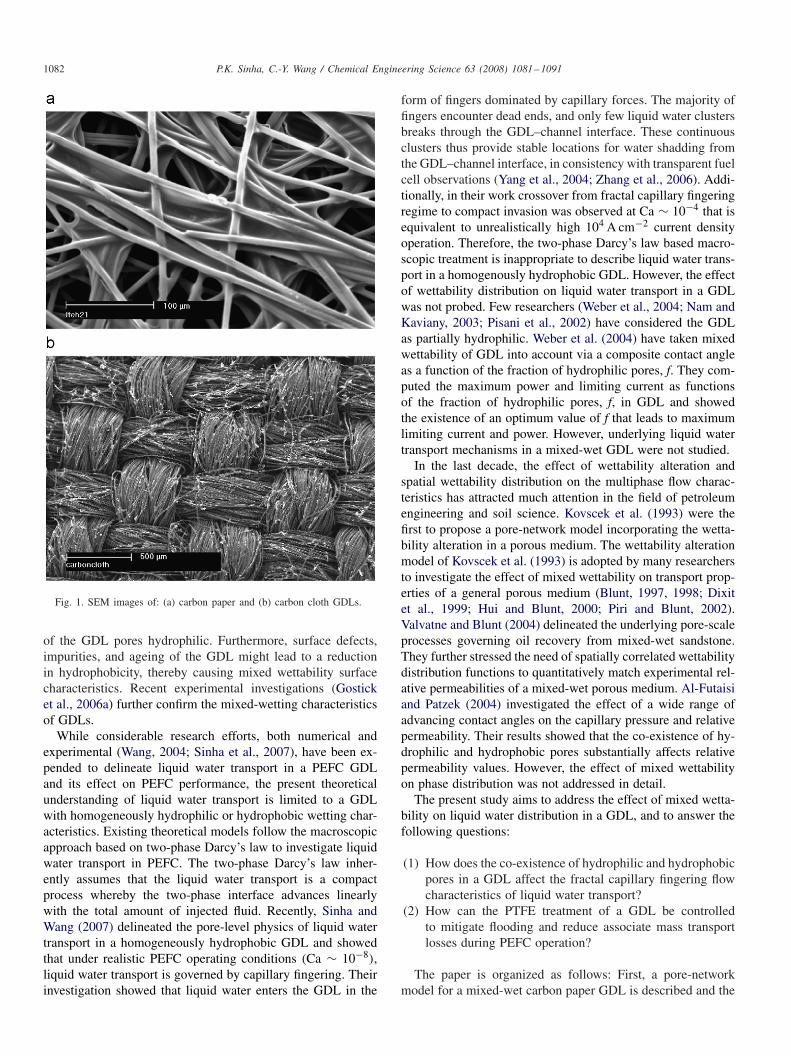
Carbon-fiber based porous materials, namely non-wovenand woven carbon paper and carbon cloth with a thickness of∼ 200 �m, are typically used for the PEFC GDL owing to theirhigh porosity (∼ 70% or higher) and good electrical/thermalconductivity. SEM micrographs of a carbon paper and a carboncloth are shown in Fig. 1. To facilitate liquid water removal fromGDL, the GDL is treated with PTFE with loading varying from5 to 30 wt% in order to induce and/or enhance hydrophobicity(Mathias et al., 2003). However, the wide range of wettingcharacteristics of carbon-based materials (Weber et al., 2004)as well as possible anomaly in the PTFE treatment renders part
1082 P.K. Sinha, C.-Y. Wang / Chemical Engineering Science 63 (2008) 1081–1091
Fig. 1. SEM images of: (a) carbon paper and (b) carbon cloth GDLs.
of the GDL pores hydrophilic. Furthermore, surface defects,impurities, and ageing of the GDL might lead to a reductionin hydrophobicity, thereby causing mixed wettability surfacecharacteristics. Recent experimental investigations (Gosticket al., 2006a) further confirm the mixed-wetting characteristicsof GDLs.
While considerable research efforts, both numerical andexperimental (Wang, 2004; Sinha et al., 2007), have been ex-pended to delineate liquid water transport in a PEFC GDLand its effect on PEFC performance, the present theoreticalunderstanding of liquid water transport is limited to a GDLwith homogeneously hydrophilic or hydrophobic wetting char-acteristics. Existing theoretical models follow the macroscopicapproach based on two-phase Darcy’s law to investigate liquidwater transport in PEFC. The two-phase Darcy’s law inher-ently assumes that the liquid water transport is a compactprocess whereby the two-phase interface advances linearlywith the total amount of injected fluid. Recently, Sinha andWang (2007) delineated the pore-level physics of liquid watertransport in a homogeneously hydrophobic GDL and showedthat under realistic PEFC operating conditions (Ca ∼ 10−8),liquid water transport is governed by capillary fingering. Theirinvestigation showed that liquid water enters the GDL in the
form of fingers dominated by capillary forces. The majority offingers encounter dead ends, and only few liquid water clustersbreaks through the GDL–channel interface. These continuousclusters thus provide stable locations for water shadding fromthe GDL–channel interface, in consistency with transparent fuelcell observations (Yang et al., 2004; Zhang et al., 2006). Addi-tionally, in their work crossover from fractal capillary fingeringregime to compact invasion was observed at Ca ∼ 10−4 that isequivalent to unrealistically high 104 A cm−2 current densityoperation. Therefore, the two-phase Darcy’s law based macro-scopic treatment is inappropriate to describe liquid water trans-port in a homogenously hydrophobic GDL. However, the effectof wettability distribution on liquid water transport in a GDLwas not probed. Few researchers (Weber et al., 2004; Nam andKaviany, 2003; Pisani et al., 2002) have considered the GDLas partially hydrophilic. Weber et al. (2004) have taken mixedwettability of GDL into account via a composite contact angleas a function of the fraction of hydrophilic pores, f. They com-puted the maximum power and limiting current as functionsof the fraction of hydrophilic pores, f, in GDL and showedthe existence of an optimum value of f that leads to maximumlimiting current and power. However, underlying liquid watertransport mechanisms in a mixed-wet GDL were not studied.
In the last decade, the effect of wettability alteration andspatial wettability distribution on the multiphase flow charac-teristics has attracted much attention in the field of petroleumengineering and soil science. Kovscek et al. (1993) were thefirst to propose a pore-network model incorporating the wetta-bility alteration in a porous medium. The wettability alterationmodel of Kovscek et al. (1993) is adopted by many researchersto investigate the effect of mixed wettability on transport prop-erties of a general porous medium (Blunt, 1997, 1998; Dixitet al., 1999; Hui and Blunt, 2000; Piri and Blunt, 2002).Valvatne and Blunt (2004) delineated the underlying pore-scaleprocesses governing oil recovery from mixed-wet sandstone.They further stressed the need of spatially correlated wettabilitydistribution functions to quantitatively match experimental rel-ative permeabilities of a mixed-wet porous medium. Al-Futaisiand Patzek (2004) investigated the effect of a wide range ofadvancing contact angles on the capillary pressure and relativepermeability. Their results showed that the co-existence of hy-drophilic and hydrophobic pores substantially affects relativepermeability values. However, the effect of mixed wettabilityon phase distribution was not addressed in detail.
The present study aims to address the effect of mixed wetta-bility on liquid water distribution in a GDL, and to answer thefollowing questions:
(1) How does the co-existence of hydrophilic and hydrophobicpores in a GDL affect the fractal capillary fingering flowcharacteristics of liquid water transport?
(2) How can the PTFE treatment of a GDL be controlledto mitigate flooding and reduce associate mass transportlosses during PEFC operation?
The paper is organized as follows: First, a pore-networkmodel for a mixed-wet carbon paper GDL is described and the
P.K. Sinha, C.-Y. Wang / Chemical Engineering Science 63 (2008) 1081–1091 1083
algorithms to simulate two-phase flow in the generated porenetwork are presented. Then, the effect of GDL hydrophilicfraction and spatial wettability distribution on liquid watertransport is elucidated. The role of controlled PTFE treatmenton flooding mitigation is discussed, and a wettability-tailoredGDL incurring the least mass transport losses is proposed.
2. Pore-network model
2.1. GDL network structure
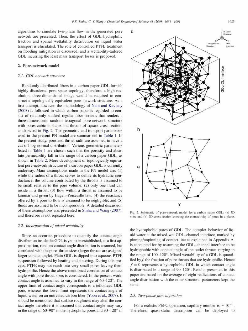
Randomly distributed fibers in a carbon paper GDL furnishhighly disordered pore space topology; therefore, a high res-olution, three-dimensional image would be required to con-struct a topologically equivalent pore-network structure. As afirst attempt, however, the methodology of Nam and Kaviany(2003) is followed in which carbon paper is regarded to con-sist of randomly stacked regular fiber screens that renders athree-dimensional random tetragonal pore-network structurewith pores cubic in shape and throats of square cross section,as depicted in Fig. 2. The geometric and transport parametersused in the present PN model are summarized in Table 1. Inthe present study, pore and throat radii are assumed to have acut-off log normal distribution. Various geometric parameterslisted in Table 1 are chosen such that the porosity and abso-lute permeability fall in the range of a carbon paper GDL, asshown in Table 2. More development of topologically equiva-lent pore-network structure of a carbon paper GDL is currentlyunderway. Main assumptions made in the PN model are: (1)while the radius of a throat serves to define its hydraulic con-ductance, the volume contributed by the throats is assumed tobe small relative to the pore volume; (2) only one fluid canreside in a throat; (3) flow within a throat is assumed to belaminar and given by Hagen–Poiseuille law; (4) the resistanceoffered by a pore to flow is assumed to be negligible; and (5)fluids are assumed to be incompressible. A detailed discussionof these assumptions was presented in Sinha and Wang (2007),and therefore is not repeated here.
2.2. Incorporation of mixed wettability
Since an accurate procedure to quantify the contact angledistribution inside the GDL is yet to be established, as a first ap-proximation, random contact angle distribution is assumed, butcorrelated with the pore–throat sizes (larger throats are assignedlarger contact angle). Plain GDL is dipped into aqueous PTFEsuspension followed by heating and sintering. During this pro-cess, PTFE may not reach into very small pores leaving themhydrophilic. Hence the above-mentioned correlation of contactangle with pore throat sizes is considered. In the present work,contact angle is assumed to vary in the range of 60–120◦. Theupper limit of contact angle corresponds to a teflonized GDLpore, whereas the lower limit represents the contact angle ofliquid water on an untreated carbon fiber (Yoon et al., 2007). Itshould be mentioned that surface roughness may alter the con-tact angle therefore it is assumed that contact angle may varyin the range of 60–90◦ in the hydrophilic pores and 90–120◦ in
Fig. 2. Schematic of pore-network model for a carbon paper GDL: (a) 3Dview and (b) 2D cross section showing the connectivity of pores in a plane.
the hydrophobic pores of GDL. The complex behavior of liq-uid water at the mixed-wet GDL–channel interface, marked bypinning/unpinning of contact line as explained in Appendix A,is accounted for by assuming the GDL–channel interface to behydrophobic with contact angle of the outlet throats varying inthe range of 100–120◦. Mixed wettability of a GDL is quanti-fied by f, the fraction of pore throats that are hydrophilic. Hencef = 0 represents a hydrophobic GDL in which contact angleis distributed in a range of 90–120◦. Results presented in thispaper are based on the average of eight realizations of contactangle distribution with the other structural parameters kept thesame.
2.3. Two-phase flow algorithm
For a realistic PEFC operation, capillary number is ∼ 10−8.Therefore, quasi-static description can be deployed to
1084 P.K. Sinha, C.-Y. Wang / Chemical Engineering Science 63 (2008) 1081–1091
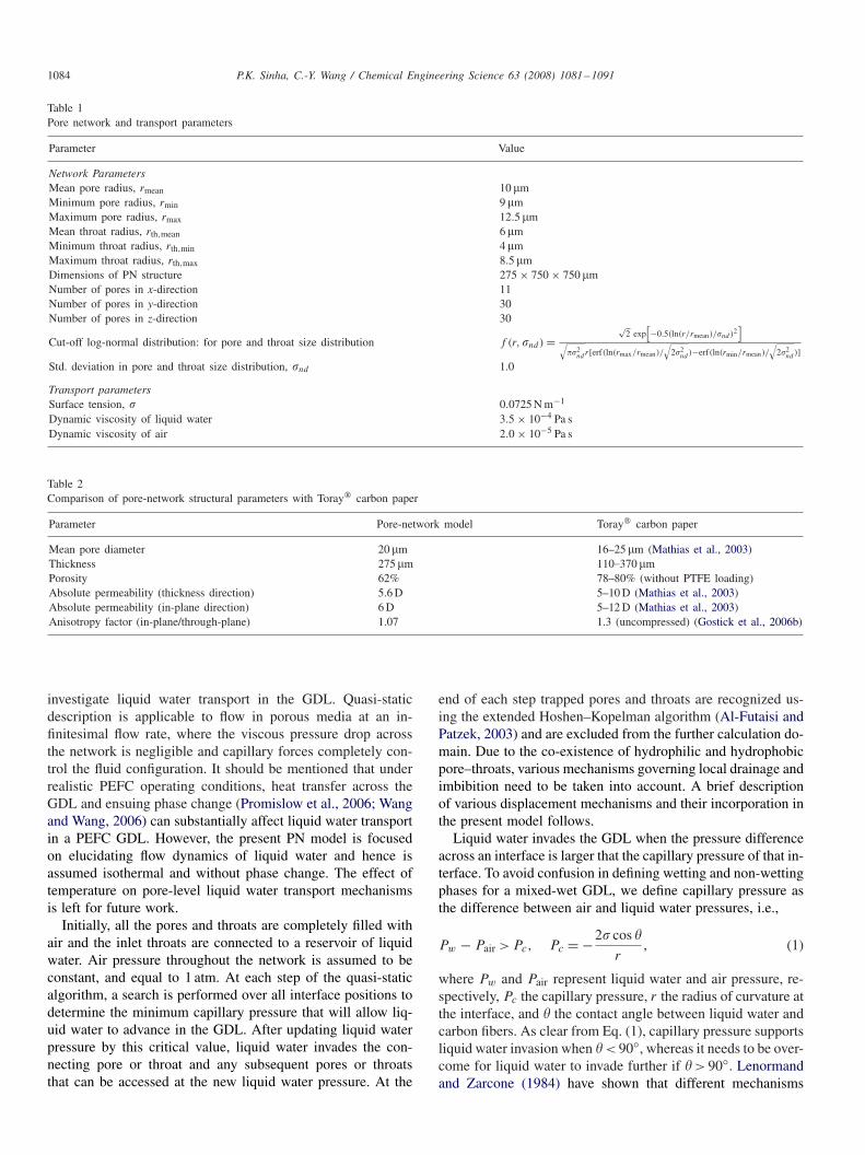
Table 1Pore network and transport parameters
Parameter Value
Network ParametersMean pore radius, rmean 10 �mMinimum pore radius, rmin 9 �mMaximum pore radius, rmax 12.5 �mMean throat radius, rth,mean 6 �mMinimum throat radius, rth,min 4 �mMaximum throat radius, rth,max 8.5 �mDimensions of PN structure 275 × 750 × 750 �mNumber of pores in x-direction 11Number of pores in y-direction 30Number of pores in z-direction 30
Cut-off log-normal distribution: for pore and throat size distribution f (r,�nd ) =√
2 exp[−0.5(ln(r/rmean)/�nd )2
]√
��2nd r[erf(ln(rmax/rmean)/
√2�2
nd )−erf(ln(rmin/rmean)/
√2�2
nd )]Std. deviation in pore and throat size distribution, �nd 1.0
Transport parametersSurface tension, � 0.0725 N m−1
Dynamic viscosity of liquid water 3.5 × 10⁻⁴ Pa sDynamic viscosity of air 2.0 × 10⁻⁵ Pa s
Table 2Comparison of pore-network structural parameters with Toray� carbon paper
Parameter Pore-network model Toray� carbon paper
Mean pore diameter 20 �m 16–25 �m (Mathias et al., 2003)Thickness 275 �m 110.370 �mPorosity 62% 78–80% (without PTFE loading)Absolute permeability (thickness direction) 5.6 D 5–10 D (Mathias et al., 2003)Absolute permeability (in-plane direction) 6 D 5–12 D (Mathias et al., 2003)Anisotropy factor (in-plane/through-plane) 1.07 1.3 (uncompressed) (Gostick et al., 2006b)
investigate liquid water transport in the GDL. Quasi-staticdescription is applicable to flow in porous media at an in-finitesimal flow rate, where the viscous pressure drop acrossthe network is negligible and capillary forces completely con-trol the fluid configuration. It should be mentioned that underrealistic PEFC operating conditions, heat transfer across theGDL and ensuing phase change (Promislow et al., 2006; Wangand Wang, 2006) can substantially affect liquid water transportin a PEFC GDL. However, the present PN model is focusedon elucidating flow dynamics of liquid water and hence isassumed isothermal and without phase change. The effect oftemperature on pore-level liquid water transport mechanismsis left for future work.
Initially, all the pores and throats are completely filled withair and the inlet throats are connected to a reservoir of liquidwater. Air pressure throughout the network is assumed to beconstant, and equal to 1 atm. At each step of the quasi-staticalgorithm, a search is performed over all interface positions todetermine the minimum capillary pressure that will allow liq-uid water to advance in the GDL. After updating liquid waterpressure by this critical value, liquid water invades the con-necting pore or throat and any subsequent pores or throatsthat can be accessed at the new liquid water pressure. At the
end of each step trapped pores and throats are recognized us-ing the extended Hoshen–Kopelman algorithm (Al-Futaisi andPatzek, 2003) and are excluded from the further calculation do-main. Due to the co-existence of hydrophilic and hydrophobicpore–throats, various mechanisms governing local drainage andimbibition need to be taken into account. A brief descriptionof various displacement mechanisms and their incorporation inthe present model follows.
Liquid water invades the GDL when the pressure differenceacross an interface is larger that the capillary pressure of that in-terface. To avoid confusion in defining wetting and non-wettingphases for a mixed-wet GDL, we define capillary pressure asthe difference between air and liquid water pressures, i.e.,
Pw − Pair > Pc, Pc = −2� cos �
r, (1)
where Pw and Pair represent liquid water and air pressure, re-spectively, Pc the capillary pressure, r the radius of curvature atthe interface, and � the contact angle between liquid water andcarbon fibers. As clear from Eq. (1), capillary pressure supportsliquid water invasion when � < 90◦, whereas it needs to be over-come for liquid water to invade further if � > 90◦. Lenormandand Zarcone (1984) have shown that different mechanisms
P.K. Sinha, C.-Y. Wang / Chemical Engineering Science 63 (2008) 1081–1091 1085
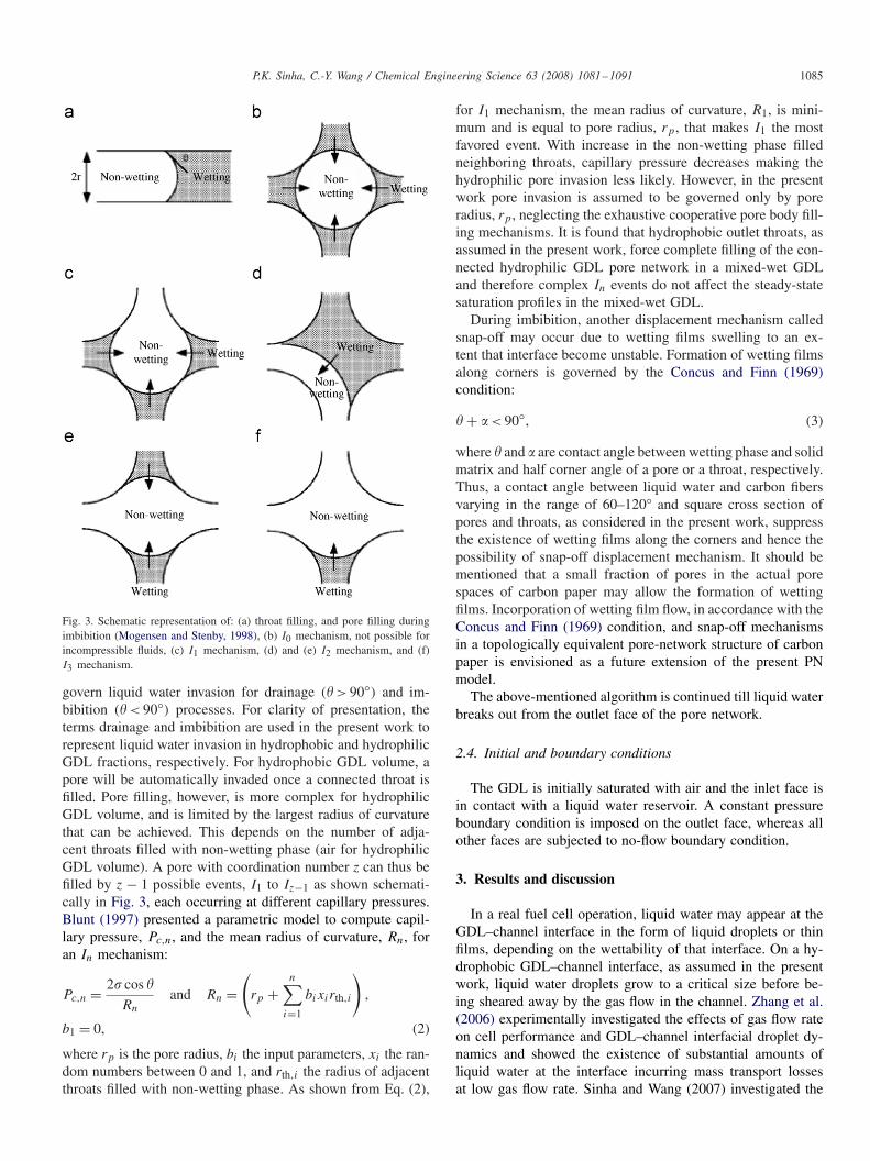
Fig. 3. Schematic representation of: (a) throat filling, and pore filling duringimbibition (Mogensen and Stenby, 1998), (b) I0 mechanism, not possible forincompressible fluids, (c) I1 mechanism, (d) and (e) I2 mechanism, and (f)I3 mechanism.
govern liquid water invasion for drainage (� > 90◦) and im-bibition (� < 90◦) processes. For clarity of presentation, theterms drainage and imbibition are used in the present work torepresent liquid water invasion in hydrophobic and hydrophilicGDL fractions, respectively. For hydrophobic GDL volume, apore will be automatically invaded once a connected throat isfilled. Pore filling, however, is more complex for hydrophilicGDL volume, and is limited by the largest radius of curvaturethat can be achieved. This depends on the number of adja-cent throats filled with non-wetting phase (air for hydrophilicGDL volume). A pore with coordination number z can thus befilled by z − 1 possible events, I1 to Iz−1 as shown schemati-cally in Fig. 3, each occurring at different capillary pressures.Blunt (1997) presented a parametric model to compute capil-lary pressure, Pc,n, and the mean radius of curvature, Rn, foran In mechanism:
Pc,n = 2� cos �
Rn
and Rn =(
rp +n∑
i=1
bixirth,i
),
b1 = 0, (2)
where rp is the pore radius, bi the input parameters, xi the ran-dom numbers between 0 and 1, and rth,i the radius of adjacentthroats filled with non-wetting phase. As shown from Eq. (2),
for I1 mechanism, the mean radius of curvature, R1, is mini-mum and is equal to pore radius, rp, that makes I1 the mostfavored event. With increase in the non-wetting phase filledneighboring throats, capillary pressure decreases making thehydrophilic pore invasion less likely. However, in the presentwork pore invasion is assumed to be governed only by poreradius, rp, neglecting the exhaustive cooperative pore body fill-ing mechanisms. It is found that hydrophobic outlet throats, asassumed in the present work, force complete filling of the con-nected hydrophilic GDL pore network in a mixed-wet GDLand therefore complex In events do not affect the steady-statesaturation profiles in the mixed-wet GDL.
During imbibition, another displacement mechanism calledsnap-off may occur due to wetting films swelling to an ex-tent that interface become unstable. Formation of wetting filmsalong corners is governed by the Concus and Finn (1969)condition:
� + � < 90◦, (3)
where � and � are contact angle between wetting phase and solidmatrix and half corner angle of a pore or a throat, respectively.Thus, a contact angle between liquid water and carbon fibersvarying in the range of 60–120◦ and square cross section ofpores and throats, as considered in the present work, suppressthe existence of wetting films along the corners and hence thepossibility of snap-off displacement mechanism. It should bementioned that a small fraction of pores in the actual porespaces of carbon paper may allow the formation of wettingfilms. Incorporation of wetting film flow, in accordance with theConcus and Finn (1969) condition, and snap-off mechanismsin a topologically equivalent pore-network structure of carbonpaper is envisioned as a future extension of the present PNmodel.
The above-mentioned algorithm is continued till liquid waterbreaks out from the outlet face of the pore network.
2.4. Initial and boundary conditions
The GDL is initially saturated with air and the inlet face isin contact with a liquid water reservoir. A constant pressureboundary condition is imposed on the outlet face, whereas allother faces are subjected to no-flow boundary condition.
3. Results and discussion
In a real fuel cell operation, liquid water may appear at theGDL–channel interface in the form of liquid droplets or thinfilms, depending on the wettability of that interface. On a hy-drophobic GDL–channel interface, as assumed in the presentwork, liquid water droplets grow to a critical size before be-ing sheared away by the gas flow in the channel. Zhang et al.(2006) experimentally investigated the effects of gas flow rateon cell performance and GDL–channel interfacial droplet dy-namics and showed the existence of substantial amounts ofliquid water at the interface incurring mass transport lossesat low gas flow rate. Sinha and Wang (2007) investigated the
1086 P.K. Sinha, C.-Y. Wang / Chemical Engineering Science 63 (2008) 1081–1091
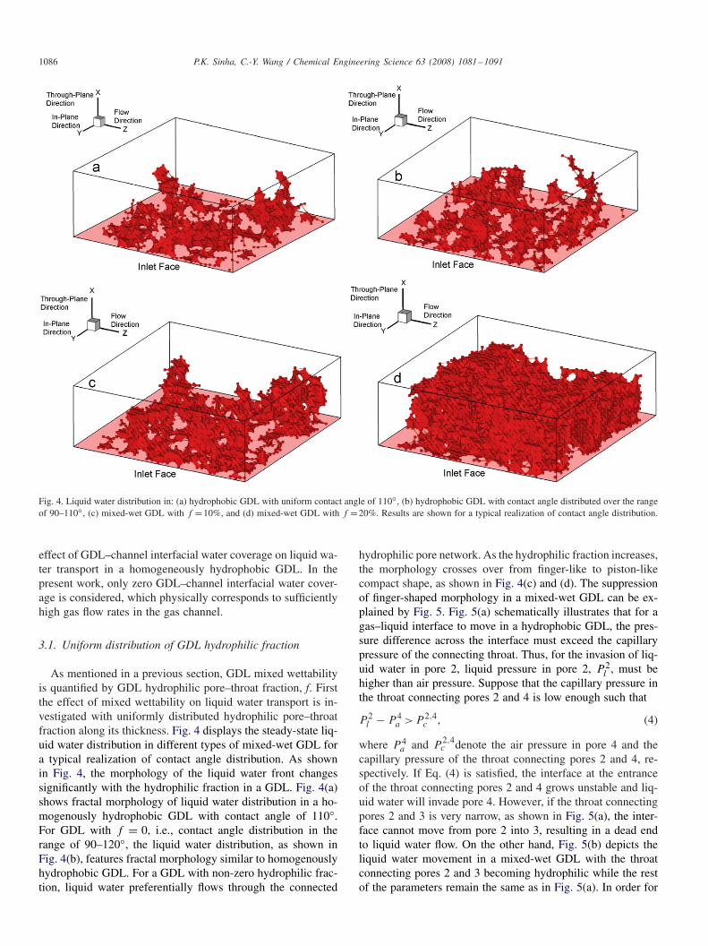
Fig. 4. Liquid water distribution in: (a) hydrophobic GDL with uniform contact angle of 110◦, (b) hydrophobic GDL with contact angle distributed over the rangeof 90–110◦, (c) mixed-wet GDL with f =10%, and (d) mixed-wet GDL with f =20%. Results are shown for a typical realization of contact angle distribution.
effect of GDL–channel interfacial water coverage on liquid wa-ter transport in a homogeneously hydrophobic GDL. In thepresent work, only zero GDL–channel interfacial water cover-age is considered, which physically corresponds to sufficientlyhigh gas flow rates in the gas channel.
3.1. Uniform distribution of GDL hydrophilic fraction
As mentioned in a previous section, GDL mixed wettabilityis quantified by GDL hydrophilic pore–throat fraction, f. Firstthe effect of mixed wettability on liquid water transport is in-vestigated with uniformly distributed hydrophilic pore–throatfraction along its thickness. Fig. 4 displays the steady-state liq-uid water distribution in different types of mixed-wet GDL fora typical realization of contact angle distribution. As shownin Fig. 4, the morphology of the liquid water front changessignificantly with the hydrophilic fraction in a GDL. Fig. 4(a)shows fractal morphology of liquid water distribution in a ho-mogenously hydrophobic GDL with contact angle of 110◦.For GDL with f = 0, i.e., contact angle distribution in therange of 90–120◦, the liquid water distribution, as shown inFig. 4(b), features fractal morphology similar to homogenouslyhydrophobic GDL. For a GDL with non-zero hydrophilic frac-tion, liquid water preferentially flows through the connected
hydrophilic pore network. As the hydrophilic fraction increases,the morphology crosses over from finger-like to piston-likecompact shape, as shown in Fig. 4(c) and (d). The suppressionof finger-shaped morphology in a mixed-wet GDL can be ex-plained by Fig. 5. Fig. 5(a) schematically illustrates that for agas–liquid interface to move in a hydrophobic GDL, the pres-sure difference across the interface must exceed the capillarypressure of the connecting throat. Thus, for the invasion of liq-uid water in pore 2, liquid pressure in pore 2, P 2
l , must behigher than air pressure. Suppose that the capillary pressure inthe throat connecting pores 2 and 4 is low enough such that
P 2l − P 4
a > P 2,4c , (4)
where P 4a and P
2,4c denote the air pressure in pore 4 and the
capillary pressure of the throat connecting pores 2 and 4, re-spectively. If Eq. (4) is satisfied, the interface at the entranceof the throat connecting pores 2 and 4 grows unstable and liq-uid water will invade pore 4. However, if the throat connectingpores 2 and 3 is very narrow, as shown in Fig. 5(a), the inter-face cannot move from pore 2 into 3, resulting in a dead endto liquid water flow. On the other hand, Fig. 5(b) depicts theliquid water movement in a mixed-wet GDL with the throatconnecting pores 2 and 3 becoming hydrophilic while the restof the parameters remain the same as in Fig. 5(a). In order for
P.K. Sinha, C.-Y. Wang / Chemical Engineering Science 63 (2008) 1081–1091 1087
1 2 3
4
1 2 3
4
1 2 3
4
Dead end
1 2 3
4
HO
HO
HI1 2 3
4
HO
HO
HI331 2 3
4
HO
HO
HI
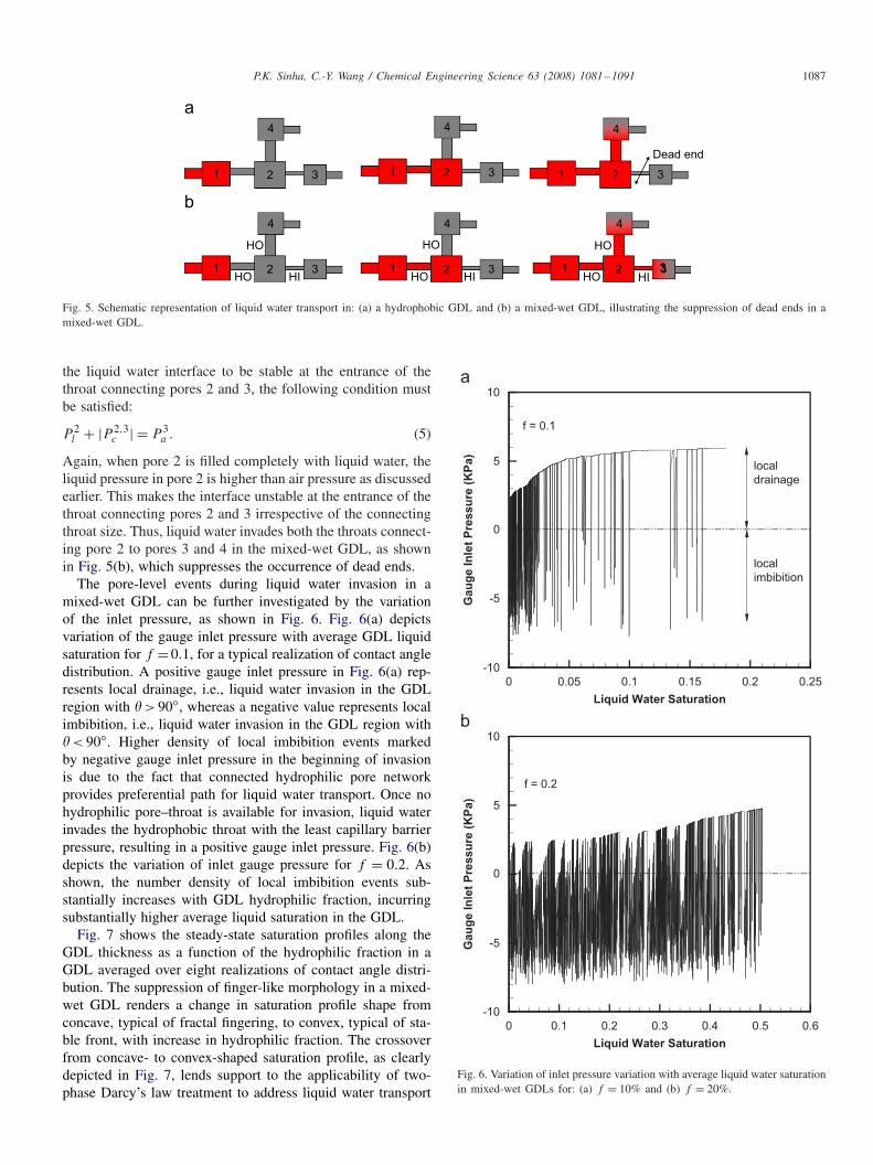
Fig. 5. Schematic representation of liquid water transport in: (a) a hydrophobic GDL and (b) a mixed-wet GDL, illustrating the suppression of dead ends in amixed-wet GDL.
the liquid water interface to be stable at the entrance of thethroat connecting pores 2 and 3, the following condition mustbe satisfied:
P 2l + |P 2,3
c | = P 3a . (5)
Again, when pore 2 is filled completely with liquid water, theliquid pressure in pore 2 is higher than air pressure as discussedearlier. This makes the interface unstable at the entrance of thethroat connecting pores 2 and 3 irrespective of the connectingthroat size. Thus, liquid water invades both the throats connect-ing pore 2 to pores 3 and 4 in the mixed-wet GDL, as shownin Fig. 5(b), which suppresses the occurrence of dead ends.
The pore-level events during liquid water invasion in amixed-wet GDL can be further investigated by the variationof the inlet pressure, as shown in Fig. 6. Fig. 6(a) depictsvariation of the gauge inlet pressure with average GDL liquidsaturation for f = 0.1, for a typical realization of contact angledistribution. A positive gauge inlet pressure in Fig. 6(a) rep-resents local drainage, i.e., liquid water invasion in the GDLregion with � > 90◦, whereas a negative value represents localimbibition, i.e., liquid water invasion in the GDL region with� < 90◦. Higher density of local imbibition events markedby negative gauge inlet pressure in the beginning of invasionis due to the fact that connected hydrophilic pore networkprovides preferential path for liquid water transport. Once nohydrophilic pore–throat is available for invasion, liquid waterinvades the hydrophobic throat with the least capillary barrierpressure, resulting in a positive gauge inlet pressure. Fig. 6(b)depicts the variation of inlet gauge pressure for f = 0.2. Asshown, the number density of local imbibition events sub-stantially increases with GDL hydrophilic fraction, incurringsubstantially higher average liquid saturation in the GDL.
Fig. 7 shows the steady-state saturation profiles along theGDL thickness as a function of the hydrophilic fraction in aGDL averaged over eight realizations of contact angle distri-bution. The suppression of finger-like morphology in a mixed-wet GDL renders a change in saturation profile shape fromconcave, typical of fractal fingering, to convex, typical of sta-ble front, with increase in hydrophilic fraction. The crossoverfrom concave- to convex-shaped saturation profile, as clearlydepicted in Fig. 7, lends support to the applicability of two-phase Darcy’s law treatment to address liquid water transport
Liquid Water Saturation
Gau
ge In
let
Pre
ssu
re (
KP
a)
0 0.05 0.1 0.15 0.2 0.25
-10
-5
0
5
10
local
drainage
local
imbibition
f = 0.1
Liquid Water Saturation
Gau
ge In
let
Pre
ssu
re (
KP
a)
0 0.1 0.2 0.3 0.4 0.5 0.6
-10
-5
0
5
10
f = 0.2
Fig. 6. Variation of inlet pressure variation with average liquid water saturationin mixed-wet GDLs for: (a) f = 10% and (b) f = 20%.
1088 P.K. Sinha, C.-Y. Wang / Chemical Engineering Science 63 (2008) 1081–1091
Fractional Distance along GDL Thickness
Liq
uid
Wate
r satu
rati
on
0.2 0.4 0.6 0.8 10
0.2
0.4
0.6
0.8
1
constant contact angle (110°)f = 0.0f = 0.1f = 0.2
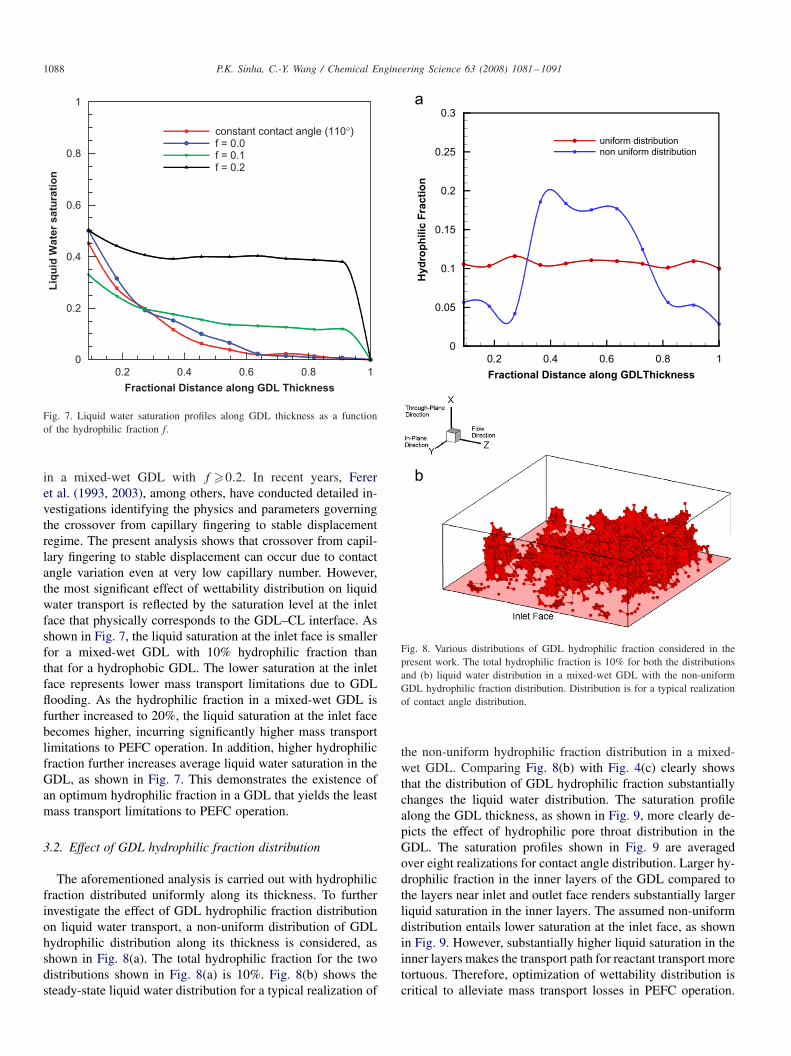
Fig. 7. Liquid water saturation profiles along GDL thickness as a functionof the hydrophilic fraction f.
in a mixed-wet GDL with f �0.2. In recent years, Fereret al. (1993, 2003), among others, have conducted detailed in-vestigations identifying the physics and parameters governingthe crossover from capillary fingering to stable displacementregime. The present analysis shows that crossover from capil-lary fingering to stable displacement can occur due to contactangle variation even at very low capillary number. However,the most significant effect of wettability distribution on liquidwater transport is reflected by the saturation level at the inletface that physically corresponds to the GDL–CL interface. Asshown in Fig. 7, the liquid saturation at the inlet face is smallerfor a mixed-wet GDL with 10% hydrophilic fraction thanthat for a hydrophobic GDL. The lower saturation at the inletface represents lower mass transport limitations due to GDLflooding. As the hydrophilic fraction in a mixed-wet GDL isfurther increased to 20%, the liquid saturation at the inlet facebecomes higher, incurring significantly higher mass transportlimitations to PEFC operation. In addition, higher hydrophilicfraction further increases average liquid water saturation in theGDL, as shown in Fig. 7. This demonstrates the existence ofan optimum hydrophilic fraction in a GDL that yields the leastmass transport limitations to PEFC operation.
3.2. Effect of GDL hydrophilic fraction distribution
The aforementioned analysis is carried out with hydrophilicfraction distributed uniformly along its thickness. To furtherinvestigate the effect of GDL hydrophilic fraction distributionon liquid water transport, a non-uniform distribution of GDLhydrophilic distribution along its thickness is considered, asshown in Fig. 8(a). The total hydrophilic fraction for the twodistributions shown in Fig. 8(a) is 10%. Fig. 8(b) shows thesteady-state liquid water distribution for a typical realization of
Fractional Distance along GDLThickness
Hyd
rop
hilic
Fra
cti
on
0.2 0.4 0.6 0.8 1
0
0.05
0.1
0.15
0.2
0.25
0.3
uniform distribution
non uniform distribution
Fig. 8. Various distributions of GDL hydrophilic fraction considered in thepresent work. The total hydrophilic fraction is 10% for both the distributionsand (b) liquid water distribution in a mixed-wet GDL with the non-uniformGDL hydrophilic fraction distribution. Distribution is for a typical realizationof contact angle distribution.
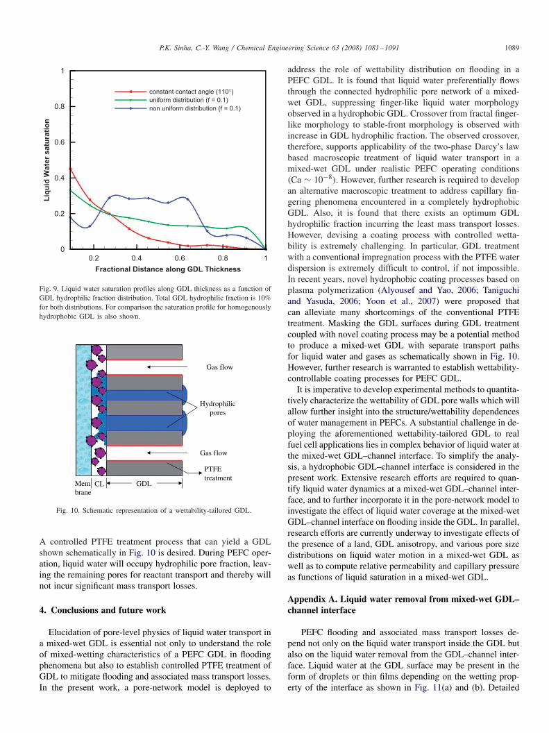
the non-uniform hydrophilic fraction distribution in a mixed-wet GDL. Comparing Fig. 8(b) with Fig. 4(c) clearly showsthat the distribution of GDL hydrophilic fraction substantiallychanges the liquid water distribution. The saturation profilealong the GDL thickness, as shown in Fig. 9, more clearly de-picts the effect of hydrophilic pore throat distribution in theGDL. The saturation profiles shown in Fig. 9 are averagedover eight realizations for contact angle distribution. Larger hy-drophilic fraction in the inner layers of the GDL compared tothe layers near inlet and outlet face renders substantially largerliquid saturation in the inner layers. The assumed non-uniformdistribution entails lower saturation at the inlet face, as shownin Fig. 9. However, substantially higher liquid saturation in theinner layers makes the transport path for reactant transport moretortuous. Therefore, optimization of wettability distribution iscritical to alleviate mass transport losses in PEFC operation.
P.K. Sinha, C.-Y. Wang / Chemical Engineering Science 63 (2008) 1081–1091 1089
Fractional Distance along GDL Thickness
Liq
uid
Wate
r satu
rati
on
0.2 0.4 0.6 0.8 1
0
0.2
0.4
0.6
0.8
1
constant contact angle (110°)uniform distribution (f = 0.1)
non uniform distribution (f = 0.1)
Fig. 9. Liquid water saturation profiles along GDL thickness as a function ofGDL hydrophilic fraction distribution. Total GDL hydrophilic fraction is 10%for both distributions. For comparison the saturation profile for homogenouslyhydrophobic GDL is also shown.
Membrane
Gas flow
Gas flow
Hydrophilicpores
PTFEtreatment
GDLCL
Fig. 10. Schematic representation of a wettability-tailored GDL.
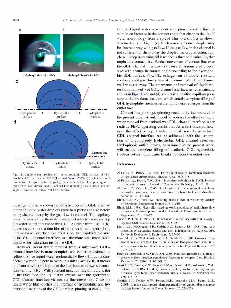
A controlled PTFE treatment process that can yield a GDLshown schematically in Fig. 10 is desired. During PEFC oper-ation, liquid water will occupy hydrophilic pore fraction, leav-ing the remaining pores for reactant transport and thereby willnot incur significant mass transport losses.
4. Conclusions and future work
Elucidation of pore-level physics of liquid water transport ina mixed-wet GDL is essential not only to understand the roleof mixed-wetting characteristics of a PEFC GDL in floodingphenomena but also to establish controlled PTFE treatment ofGDL to mitigate flooding and associated mass transport losses.In the present work, a pore-network model is deployed to
address the role of wettability distribution on flooding in aPEFC GDL. It is found that liquid water preferentially flowsthrough the connected hydrophilic pore network of a mixed-wet GDL, suppressing finger-like liquid water morphologyobserved in a hydrophobic GDL. Crossover from fractal finger-like morphology to stable-front morphology is observed withincrease in GDL hydrophilic fraction. The observed crossover,therefore, supports applicability of the two-phase Darcy’s lawbased macroscopic treatment of liquid water transport in amixed-wet GDL under realistic PEFC operating conditions(Ca ∼ 10−8). However, further research is required to developan alternative macroscopic treatment to address capillary fin-gering phenomena encountered in a completely hydrophobicGDL. Also, it is found that there exists an optimum GDLhydrophilic fraction incurring the least mass transport losses.However, devising a coating process with controlled wetta-bility is extremely challenging. In particular, GDL treatmentwith a conventional impregnation process with the PTFE waterdispersion is extremely difficult to control, if not impossible.In recent years, novel hydrophobic coating processes based onplasma polymerization (Alyousef and Yao, 2006; Taniguchiand Yasuda, 2006; Yoon et al., 2007) were proposed thatcan alleviate many shortcomings of the conventional PTFEtreatment. Masking the GDL surfaces during GDL treatmentcoupled with novel coating process may be a potential methodto produce a mixed-wet GDL with separate transport pathsfor liquid water and gases as schematically shown in Fig. 10.However, further research is warranted to establish wettability-controllable coating processes for PEFC GDL.
It is imperative to develop experimental methods to quantita-tively characterize the wettability of GDL pore walls which willallow further insight into the structure/wettability dependencesof water management in PEFCs. A substantial challenge in de-ploying the aforementioned wettability-tailored GDL to realfuel cell applications lies in complex behavior of liquid water atthe mixed-wet GDL–channel interface. To simplify the analy-sis, a hydrophobic GDL–channel interface is considered in thepresent work. Extensive research efforts are required to quan-tify liquid water dynamics at a mixed-wet GDL–channel inter-face, and to further incorporate it in the pore-network model toinvestigate the effect of liquid water coverage at the mixed-wetGDL–channel interface on flooding inside the GDL. In parallel,research efforts are currently underway to investigate effects ofthe presence of a land, GDL anisotropy, and various pore sizedistributions on liquid water motion in a mixed-wet GDL aswell as to compute relative permeability and capillary pressureas functions of liquid saturation in a mixed-wet GDL.
Appendix A. Liquid water removal from mixed-wet GDL–channel interface
PEFC flooding and associated mass transport losses de-pend not only on the liquid water transport inside the GDL butalso on the liquid water removal from the GDL–channel inter-face. Liquid water at the GDL surface may be present in theform of droplets or thin films depending on the wetting prop-erty of the interface as shown in Fig. 11(a) and (b). Detailed
1090 P.K. Sinha, C.-Y. Wang / Chemical Engineering Science 63 (2008) 1081–1091
Hydrophilicsurface
Hydrophobicsurface
Hydrophobicsurface
Hydrophobicsurface
Hydrophobicsurface
Hydrophobicsurface
Hydrophobic (θ θ > 90°) Hydrophilic (0°<θ θ <90°)
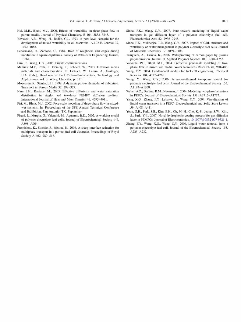
Fig. 11. Liquid water droplets on: (a) hydrophobic GDL surface; (b) hy-drophilic GDL surface at 70 ◦C (Lim and Wang, 2003), (c) schematic rep-resentation of liquid water droplet growth with contact line pinning on amixed-wet GDL surface, and (d) contact line unpinning once a critical contactangle is reached on mixed-wet GDL surface.
investigations have shown that on a hydrophobic GDL–channelinterface liquid water droplets grow to a particular size beforebeing sheared away by the gas flow in channel. The capillarypressure exerted by these droplets substantially increases liq-uid water saturation inside the GDL. As clear from Fig. 11(b),due to its curvature, a thin film of liquid water on a hydrophilicGDL–channel interface will exert a positive capillary pressureat the GDL–channel interface, and therefore will force 100%liquid water saturation inside the GDL.
However, liquid water removal from a mixed-wet GDL–channel interface is more complex, and can be envisioned asfollows: Since liquid water preferentially flows through a con-nected hydrophilic pore network in a mixed-wet GDL, it breaksout from a hydrophilic pore at the interface, as shown schemat-ically in Fig. 11(c). With constant injection rate of liquid waterat the inlet face, the liquid film spreads over the hydrophilicGDL–channel interface via contact line movement. Once theliquid water film touches the interface of hydrophilic and hy-drophobic sections of the GDL surface, pinning of contact line
occurs. Liquid water movement with pinned contact line re-sults in an increase in the contact angle that changes the liquidwater morphology from a spread film to a droplet as shownschematically in Fig. 11(c). Such a newly formed droplet maybe sheared away with gas flow. If the gas flow in the channel isnot sufficient to shear away the droplet, the droplet contact an-gle will keep increasing till it reaches a threshold value, �c, thatunpins the contact line. Further movement of contact line overthe GDL–channel interface will cause enlargement of dropletsize with change in contact angle according to the hydropho-bic GDL surface, �HO. The enlargement of droplet size willcontinue until gas flow shears it or more hydrophilic channelwall wicks it away. The emergence and removal of liquid wa-ter from a mixed-wet GDL–channel interface, as schematicallyshown in Figs. 11(c) and (d), results in a positive capillary pres-sure at the breakout location, which entails complete filling ofGDL hydrophilic fraction before liquid water emerges from theoutlet face.
Contact line pinning/unpinning needs to be incorporated inthe present pore-network model to address the effect of liquidwater removal from a mixed-wet GDL–channel interface underrealistic PEFC operating conditions. As a first attempt, how-ever, the effect of liquid water removal from the mixed-wetGDL–channel interface can be addressed with the assump-tion of a completely hydrophobic GDL–channel interface.Hydrophobic outlet throats, as assumed in the present work,will ensure complete filling of available GDL hydrophilicfraction before liquid water breaks out from the outlet face.
References
Al-Futaisi, A., Patzek, T.W., 2003. Extension of Hoshen–Kopleman algorithmto non-lattice environments. Physica A 321, 665–678.
Al-Futaisi, A., Patzek, T.W., 2004. Secondary imbibition in NAPL-invadedmixed-wet sediments. Journal of Contaminant Hydrology 74, 61–81.
Alyousef, Y., Yao, S.C., 2006. Development of a silicon-based wettabilitycontrolled membrane for microscale direct methanol fuel cells. MicrofluidNanofluid 2, 337–344.
Blunt, M.J., 1997. Pore level modeling of the effects of wettability. Societyof Petroleum Engineering Journal 2, 449–510.
Blunt, M.J., 1998. Physically based network modeling of multiphase flowin intermediate-wet porous media. Journal of Petroleum Science andEngineering 20, 117–125.
Concus, P., Finn, R., 1969. On the behavior of a capillary surface in a wedge.Applied Mathematical Sciences 63, 292–299.
Dixit, A.B., McDougall, S.R., Sorbie, K.S., Buckley, J.S., 1999. Pore-scalemodeling of wettability effects and their influence on oil recovery. SPEReservoir Evaluation & Engineering 2, 25–36.
Ferer, M., Sams, W.N., Geisbrecht, R.A., Smith, D.H., 1993. Crossover fromfractal to compact flow from simulations of two-phase flow with finiteviscosity ratio in two-dimensional porous media. Physical Review E 47,2713–2723.
Ferer, M., Bromhal, G.S., Smith, D.H., 2003. Pore-level modeling of drainage:crossover from invasion percolation fingering to compact flow. PhysicalReview E 67, 051601-1–051601-12.
Gostick, J.T., Fowler, M.W., Ioannidis, M.A., Pritzer, M.D., Volfkovich, Y.M.,Sakars, A., 2006a. Capillary pressure and hydrophilic porosity in gasdiffusion layers for polymer electrolyte fuel cells. Journal of Power Sources156, 375–387.
Gostick, J.T., Fowler, M.W., Pritzer, M.D., Ioannidis, M.A., Behra, L.M.,2006b. In-plane and through-plane permeability of carbon-fiber electrodebacking layers. Journal of Power Sources 162, 228–238.
P.K. Sinha, C.-Y. Wang / Chemical Engineering Science 63 (2008) 1081–1091 1091
Hui, M.H., Blunt, M.J., 2000. Effects of wettability on three-phase flow inporous media. Journal of Physical Chemistry, B 104, 3833–3845.
Kovscek, A.R., Wong, H., Radke, C.J., 1993. A pore-level scenario for thedevelopment of mixed wettability in oil reservoirs. A.I.Ch.E. Journal 39,1072–1085.
Lenormand, R., Zarcone, C., 1984. Role of roughness and edges duringimbibition in square capillaries. Society of Petroleum Engineering Journal,13264.
Lim, C., Wang, C.Y., 2003. Private communications.Mathias, M.F., Roth, J., Fleming, J., Lehnert, W., 2003. Diffusion media
materials and characterization. In: Lietsich, W., Lamm, A., Gasteiger,H.A. (Eds.), Handbook of Fuel Cells—Fundamentals, Technology andApplications, vol. 3, Wiley, Chicester, p. 517.
Mogensen, K., Stenby, E.H., 1998. A dynamic pore-scale model of imbibition.Transport in Porous Media 32, 299–327.
Nam, J.H., Kaviany, M., 2003. Effective diffusivity and water saturationdistribution in single- and two-layer PEMFC diffusion medium.International Journal of Heat and Mass Transfer 46, 4595–4611.
Piri, M., Blunt, M.J., 2002. Pore-scale modeling of three-phase flow in mixed-wet systems. In: Proceedings of the SPE Annual Technical Conferenceand Exhibition, San Antonio, TX, September.
Pisani, L., Murgia, G., Valentini, M., Aguanno, B.D., 2002. A working modelof polymer electrolyte fuel cells. Journal of Electrochemical Society 149,A898–A904.
Promislow, K., Stockie, J., Wetton, B., 2006. A sharp interface reduction formultiphase transport in a porous fuel cell electrode. Proceedings of RoyalSociety A 462, 789–816.
Sinha, P.K., Wang, C.Y., 2007. Pore-network modeling of liquid watertransport in gas diffusion layer of a polymer electrolyte fuel cell.Electrochimica Acta 52, 7936–7945.
Sinha, P.K., Mukherjee, P.P., Wang, C.Y., 2007. Impact of GDL structure andwettability on water management in polymer electrolyte fuel cells. Journalof Materials Chemistry 17, 3089–3103.
Taniguchi, A., Yasuda, K., 2006. Waterproofing of carbon paper by plasmapolymerization. Journal of Applied Polymer Science 100, 1748–1753.
Valvatne, P.H., Blunt, M.J., 2004. Predictive pore-scale modeling of two-phase flow in mixed wet media. Water Resources Research 40, W07406.
Wang, C.Y., 2004. Fundamental models for fuel cell engineering. ChemicalReviews 104, 4727–4766.
Wang, Y., Wang, C.Y., 2006. A non-isothermal two-phase model forpolymer electrolyte fuel cells. Journal of the Electrochemical Society 153,A1193–A1200.
Weber, A.Z., Darling, R.M., Newman, J., 2004. Modeling two-phase behaviorsin PEFCs. Journal of Electrochemical Society 151, A1715–A1727.
Yang, X.G., Zhang, F.Y., Lubawy, A., Wang, C.Y., 2004. Visualization ofliquid water transport in a PEFC. Electrochemical and Solid State Letters59, A408–A411.
Yoon, G.H., Park, S.B., Kim, E.H., Oh, M.-H., Cho, K.-S., Jeong, S.W., Kim,S., Park, Y.-I., 2007. Novel hydrophobic coating process for gas diffusionlayer in PEMFCs, Journal of Electroceramics, 10.1007/s10832-007-9321-1.
Zhang, F.Y., Wang, X.G., Wang, C.Y., 2006. Liquid water removal from apolymer electrolyte fuel cell. Journal of the Electrochemical Society 153,A225–A232.