Study of Employee Welfare in Merchant Ships employing Indian ...
Upload
independentCategory
view
2download
0
Author's personal copy
A direct borohydride fuel cell employing a sago gel polymerelectrolyte
A. Jamaludin, Z. Ahmad, Z.A. Ahmad, A.A. Mohamad*
School of Materials and Mineral Resources Engineering, Universiti Sains Malaysia, 14300 Nibong Tebal, Penang, Malaysia
a r t i c l e i n f o
Article history:
Received 7 May 2010
Received in revised form
6 July 2010
Accepted 6 July 2010
Available online 11 August 2010
Keywords:
Direct borohydride fuel cell
Gel polymer electrolyte
Sago
Oxygen consumption
a b s t r a c t
The electrochemistry of a direct borohydride fuel cell based on a gel polymer electrolyte
was studied. Sago is a type of natural polymer, was employed as the polymer host for the
electrolyte. An electrolyte with a composition of sago ! 6 M KOH ! 2 M NaBH4 was
prepared and evaluated as a novel gel polymer electrolyte for a direct borohydride fuel cell
system because it exhibited a high electrical conductivity of 0.270 S cm"1. The rate at which
oxygen was consumed at the cathode can be related to the electric current by comparing
the calculated number of electrons reacted per molecule of oxygen for different currents
supplied to the fuel cell. From the oxygen consumption data, it was deduced that four
electrons reacted per molecule of oxygen. The performance of the fuel cell was measured
in terms of its currentevoltage, discharge and open circuit voltage measurements. The
maximum power density obtained was 8.818 mW cm"2 at a discharge performance of
w230 mA h and nominal voltage of 0.806 V. The open circuit voltage of the cells was about
0.900 V and sustained for 23 h.
ª 2010 Professor T. Nejat Veziroglu. Published by Elsevier Ltd. All rights reserved.
1. Introduction
Fuel cells are energy conversion device which have become anattractive alternative energy source to oil, natural gas andconventional fossil fuel combustion engine [1,2]. A fuel cellconverts chemical energy into electrical energy and generates
electricity as long as fuel and oxidant are supplied into thesystem. Among the assorted types of fuel cells available,H2eO2 fuel cells gained more attention as they produce purewater as a byproduct. Alkaline fuel cell (AFC) is one type of fuelcell classified as H2eO2 fuel cell. In fact, AFC has an advantagebecause the less corrosive nature of AFC’s componentsensures a greater potential longevity [3]. An AFC that directlyutilizes a borohydride compound as fuel in an aqueous alka-line medium is termed a direct borohydride fuel cell (DBFC).DBFCs are one of the most exciting energy technologiesdeveloped to solve the hydrogen storage and fuel efficiency
issue [4e6]. Their electric performances can be enhanced byusing an aqueous solution of potassium borohydride (KBH4) orsodium borohydride (NaBH4) [7,8]. They are grouped ascomplex hydrides containing large amounts of hydrogen. Forexample, NaBH4 contains 10.6 wt.% of hydrogen [9]. Further-more, borohydride is chemically stable and non-combustible
hence easy to be store. The reaction product is also recyclable[10]. The chemical reactions at the anode and cathode ina DBFC are given by the following:
Anode reaction : 2H2 ! 4OH"/4H2O! 4e" (1)
Cathode : O2 ! 2H2O! 4e"/4OH" (2)
Overall net reaction : 2H2 !O2/2H2O (3)
A critical safety issue arises, however, from the leakageand evaporation of the conventional alkaline aqueous
* Corresponding author. Tel.: !604 599 6118; fax: !604 594 1011.E-mail address: [email protected] (A.A. Mohamad).
Avai lab le a t www.sc iencedi rec t .com
journa l homepage : www.e lsev ier . com/ loca te /he
i n t e r n a t i o n a l j o u r n a l o f h y d r o g e n en e r g y 3 5 ( 2 0 1 0 ) 1 1 2 2 9e1 1 2 3 6
0360-3199/$ e see front matter ª 2010 Professor T. Nejat Veziroglu. Published by Elsevier Ltd. All rights reserved.doi:10.1016/j.ijhydene.2010.07.037
Author's personal copy
electrolyte employed in an AFC system. Instead of utilizing
a solid electrolyte that gives poor conductivity and poorsurface contact, the introduction of the gel polymer elec-trolyte (GPE) into a DBFC system was found to be the bestalternative.
To be applied in fuel cells or any other electrochemicaldevices, GPEs need to exhibit high ionic conductivity and anability to sustain high electrochemical activities. Therefore,a suitable polymer hostmust be chosen to ensure that the GPEhas good characteristics. Recently, electrolytes based onnatural polymers, such as starch [11,12], cellulose [13] andchitosan [14e16], have been proposed. Sago, or metroxylon
sago, is another possible candidate starch to be the polymerhost to produce the GPE. Sago is awhite, tasteless and odorlessnatural polymer possessing biodegradability and low toxicity.Furthermore, sago exhibits gel-like characteristics when dis-solved in water.
In the present work, the possibility of using sago as a gelwas investigated. Sago-based GPEs with an optimum compo-sition of potassium hydroxide (KOH) and NaBH4 wereprepared to achieve high ionic conductivities. The influence ofdifferent concentrations of KOH and NaBH4 in the GPE wereinvestigated by impedance spectroscopy and viscosity
studies. The electrochemical properties of the DBFCs werethen studied through oxygen consumption, discharge char-acteristic, open circuit voltage (Voc), currentevoltage (IeV) andcurrent densityepower-density (JeP) measurements.
2. Experimental
Sago powder (Nee Seng Ngeng & Sons Sago Industries Sdn.Bhd., Sarawak), KOH (Merck) and NaBH4 (Sigma Aldrich)were used as the starting materials in the preparation of theGPEs. Firstly, 2.0 g of sago powder was added to 20 ml ofdeionized water, and the mixture was stirred and heateduntil the sago powder was fully dissolved and formeda transparent gel solution. The gel solution was then cooledto room temperature. After that, 20 ml of KOH solution wasadded to the gel solution in different concentrations.Homogenization of the GPE was achieved by continuously
stirring the mixed solutions. Finally, the GPE preparationwas followed by the addition of different concentrations of20 ml NaBH4 solution. The KOH pellets and NaBH4 granuleswere not directly added to the sago gel solution to preventagglomeration. The compositions of the samples weresago ! x M KOH ! y M NaBH4, where x # 0, 1, 2, 3, 4, 5, 6, 7, 8and 9, and y # 0, 1, 2 and 3.
Conductivity measurements of the GPE samples were thencarried out using an Autolab PGSTAT 30 system witha frequency response analyzer (FRA) module at roomtemperature. The samples were connected to the systemusing a Teflon casing with stainless steel (SS) electrodes and
a spacer filled with the GPE. The conductivities of the GPEsamples without fuel addition were measured first, followedby the GPE samples with fuel addition. The bulk resistances(Rb) of the GPE samples obtained from the impedance spec-trum were collected over a frequency range between 0.1 Hzand 1.0 MHz with amplitude of 0.01 V.
Viscosity (h) measurements were then carried out for three
batches of GPE samples. The first batch was pure sago GPEswith different weights of sago powder in deionized water. Thesecond batch was sago GPEs with different KOH concentra-tions, and the final batch was sago ! KOH GPEs with differentNaBH4 concentrations. The preparation methods of thesamples were same as for the conductivity measurements.The viscosities of the samples were measured using a Haakeviscotester VT550 at room temperature.
The commercial anode, C/Ni (ECT, UK), was placed at thebottom of a plastic beaker, while the commercial cathode,MnOx/C fiber on Ni mesh (ECT, UK), was attached to one of the
open ends of a hollow plastic cylinder. Both the anode andcathode had an active area of 16.0 cm2. The prepared 60 ml ofsago ! KOH ! NaBH4 GPE solution was then poured into thebeaker to fill the space between the anode and cathode. Thedistance between anode and cathode is 1.2 cm. One side of thecathode was in contact with the GPE solution, while the otherside was exposed to the air. In order to measure the currentand voltage of the DBFC system, two wires were connected tothe anode and cathode terminals.
The performance of the DBFC system was evaluated byemploying the optimum GPE composition that gave the best
conductivity value. Firstly, oxygen (O2) consumption at thecathode in the DBFC system was measured by the gas-displacement method. From the O2 reduction reaction occur-ring at the cathode as shown in Eq. (2), the rate at which the O2
was consumed can be related to the electric current. Thenumbers of electrons reacted per molecule of oxygen werecalculated by dividing the number of electrons that flowedround the circuit by the number of oxygenmolecules involvedin the reaction. The ideal gas law formula, as shown in Eq. (4),was used in the calculation.
PV # nRT (4)
where P is the atmospheric pressure, V is the volume ofwater rose in the pipette, n is the amount of oxygen gas inmoles, R is the gas constant, and T is the room temperature.
The fuel cell was connected to a variable resistor in series withan ammeter. The oxygen consumption measurement kit wasalso set up with a clamped 10 ml pipette, which was con-nected to the fuel cell with a flexible tube. The pipette was halfimmersed in a beaker filled with water. The variable resistorwas adjusted to control the current flow within a range ofbetween 20 and 80mA. Once the circuit was completed, it wasobserved that thewater level rose up the pipette very slowly. Atimer was started when the water level inside the pipette wasjust above the outside level. The time for the water level tochange by 1.0 cm3 was taken. While the water was rising, the
load resistor was adjusted to keep the current constant. Afterthat, the load was disconnected, and the pipette was removedfrom the water to empty it and then replaced. These stepswere repeated with different currents.
The discharge profile at a constant current of 10.0 mA andthe Voc of the DBFC system were also evaluated using a New-are BTS. In order to plot the IeV and JeP curves, the DBFC wasdischarged with various current ranges using an AutolabPGSTAT 30 with a general purpose electrochemical system(GPES) module. All the measurements and evaluations werecarried out at room temperature.
i n t e rn a t i o n a l j o u r n a l o f h y d r o g e n en e r g y 3 5 ( 2 0 1 0 ) 1 1 2 2 9e1 1 2 3 611230
Author's personal copy
3. Results and discussion
3.1. Sago gel polymer electrolyte characterization:conductivity
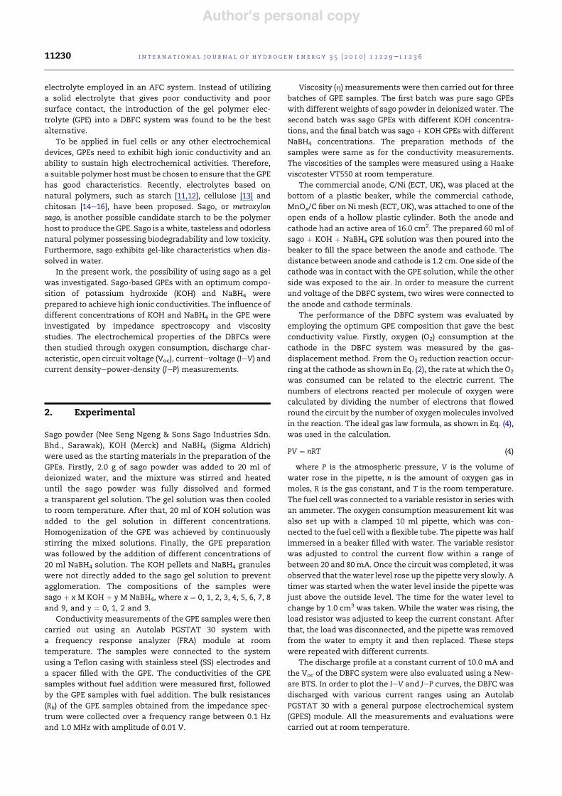
Fig. 1 shows the Nyquist plot for the GPE based on sago andKOH. The results show that with the addition of KOH to thesago gel, the plots were identified by non-vertical spikesintersecting on the Zr axis. These behaviors were presumablydue to an inhomogeneous electrode/electrolyte surfacecontact. However, the spike angles were just slightly (about80$) lower than the theoretical perpendicular angle. The
performance of these gels were therefore better than thereported impedance spectrum performance of solid polymerelectrolytes, which had spike angles of less than 70$ [17]. Fig. 1(a) gives the average Rb value for the pure sago GPE at(1027 % 80) U. The addition of KOH into the sago GPE signifi-cantly decreased the bulk resistance in the electrolyte system.The average Rb value for the sago GPEwith 3MKOHaddedwas(1.154% 0.020)Uwhile the lowest Rb valuewas (0.675% 0.003)Uwith 6 M KOH added, as presented in Fig. 1(b) and (c) respec-tively. However, the Rb value was slightly increased to(0.688 % 0.016) U when a high concentration of 9 M KOH was
added, as shown in Fig. 1(d).The Rb valueswere then converted into ionic conductivities
(s) using the following equation:
s # tRbA
(5)
where t is the thicknessof theTeflonspacerwhere thesagoGPEfills, and A is the electrode/electrolyte surface contact area.Fig. 2 shows thedependenceof the conductivity of the sagoGPE
with different concentrations of KOH. The pure sago GPE hada very low conductivity of (2.01% 15.7)& 10"4 S cm"1. The ionicconductivity increased steadily as 1 M KOH was introducedinto the sago GPE. As the concentration of KOHwas increased,the ionic conductivity increased sharply from the order of10"4 S cm"1 to 10"1 S cm"1. The ionic conductivity continued toincrease as greater concentrations of KOHwas added until 6 MKOH is reached. The highest ionic conductivity value at this
Fig. 1 e Impedance plot for GPEs with different concentrations of KOH: (a) pure sago, (b) 1e3 M KOH, (c) 4e6 M KOH and (d)7e9 M KOH.
Fig. 2 e Conductivity dependence of the sago gel polymerelectrolyte with different concentrations of KOH at 25 $C.
i n t e r n a t i o n a l j o u r n a l o f h y d r o g e n en e r g y 3 5 ( 2 0 1 0 ) 1 1 2 2 9e1 1 2 3 6 11231
Author's personal copy
point was (3.05 % 0.01) & 10"1 S cm"1. Beyond 6 M of KOH, theionic conductivity decreased slightly and then remained
constant. This conductivityof thesagoGPEwashigher than thealkaline solid polymer electrolyte which had conductivity onthe order of 10"4 S cm"1 [18,19].
The observed trend of ionic conductivity results can beexplained by the following. The pure sago GPE had a very lowconductivity, which may be attributed to possible impuritiespresent.TheeffectofKOHadditioncanbeseenclearly fromthesteady increase in the ionic conductivity of the sago GPE. KOHsupplied free OH" ions which are the charge carriers in theelectrolyte system.At lowerconcentrationsofKOH, fewchargecarriersexistedso that ionic conductivity correspondinglykept
low in value [20]. The addition of higher concentrations of KOHincreased the ionic conductivity due to an increase in thenumber of OH" ions available in the electrolyte. However, the
ionic conductivity dropped slightly and remained constant
once a maximumwas reached at 6 M KOH added. This can beexplained by the limitations of the free charge carrier. As theKOHconcentration increased, the free ionswould tend to comecloser to each other, resulting in the formation of ion pairs. Ionpairs are held together byCoulombattraction,which is a directconsequent of the mass law effect on ionization equilibria inelectrolytic solutions. Therefore, the number of free ions willdecrease at high concentrations and result in the observeddecrease in conductivity.
NaBH4was added into the sago GPE as the fuel for the DBFCsystem. Because the dissolved NaBH4 was directly added into
the system, the hydrogen gas (H2) would be readily availablefor the hydrogen oxidation reaction at the anode without anyexternal supply. The H2 was produced through hydrolysis ofNaBH4 as shown in Eq. (6). The presence of the borate productwould not interfere the system because it is relatively inert [1]:
NaBH4 ! 2H2O/NaBO2 ! 4H2 (6)
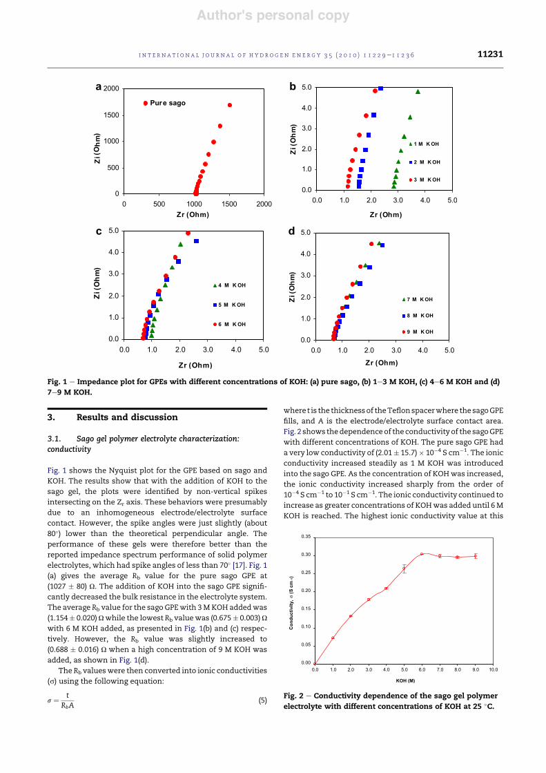
It was expected that adding more NaBH4 into the sago GPEwould improve the conductivity of the sago GPE. However,there was fluctuation in conductivity as seen in Fig. 3 due tothe effervescence of H2 (g) from the system since the H2 affectthe conductivity of GPE system. The presence of H2 mayprovide extra energy to the GPE system, thereby enhancing or/and interfering the mobility of the charge carriers. The GPE
with the optimum composition of sago ! 6 M KOH ! 2 MNaBH4 gave the best conductivity of (0.270% 0.005) S cm"1 andwas chosen to be employed in the DBFC fabrication.
3.2. Sago gel polymer electrolyte characterization:viscosity
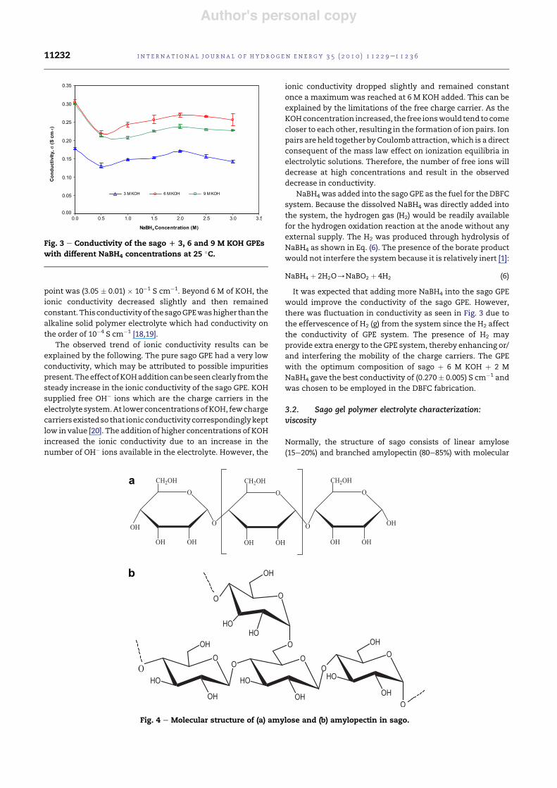
Normally, the structure of sago consists of linear amylose(15e20%) and branched amylopectin (80e85%) with molecular
Fig. 3 e Conductivity of the sago D 3, 6 and 9 M KOH GPEswith different NaBH4 concentrations at 25 $C.
a
b
Fig. 4 e Molecular structure of (a) amylose and (b) amylopectin in sago.
i n t e rn a t i o n a l j o u r n a l o f h y d r o g e n en e r g y 3 5 ( 2 0 1 0 ) 1 1 2 2 9e1 1 2 3 611232
Author's personal copy
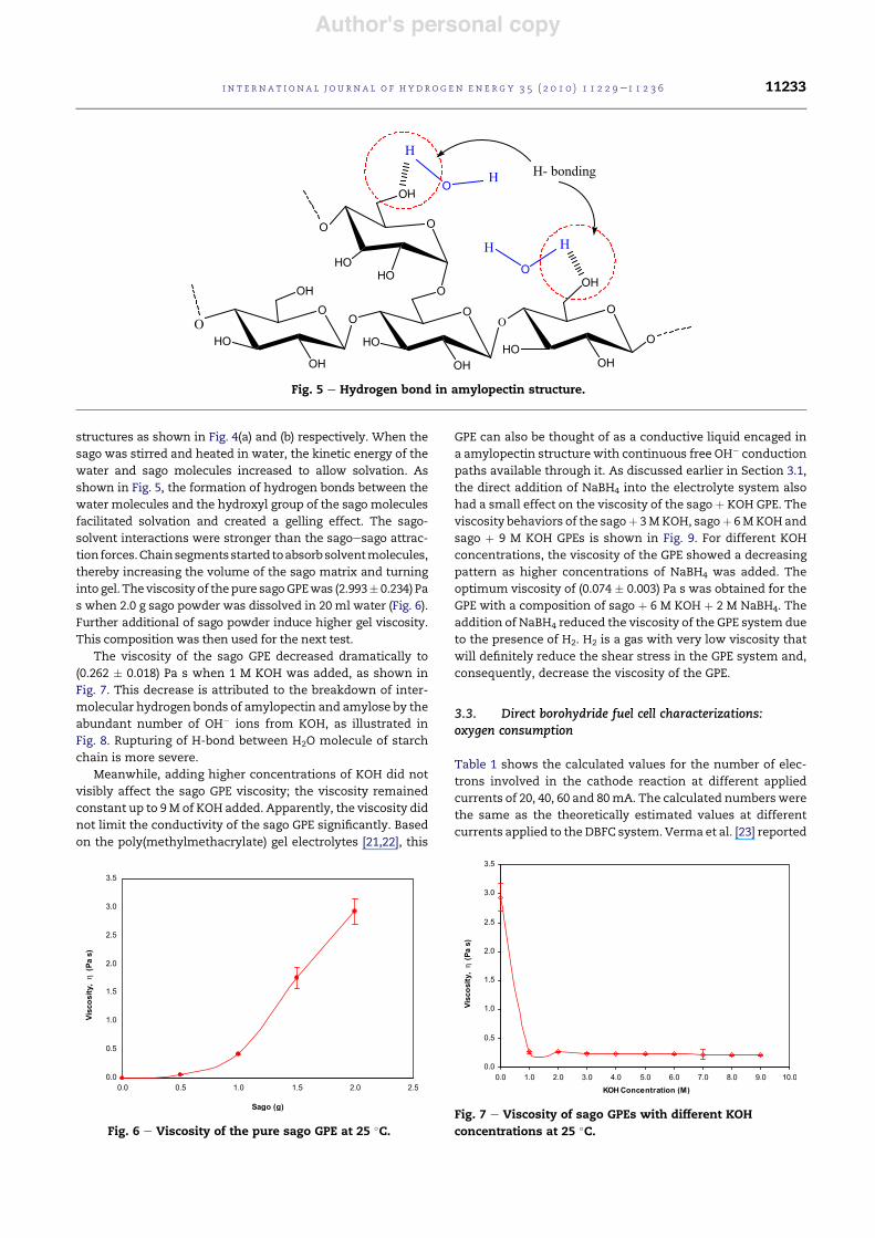
structures as shown in Fig. 4(a) and (b) respectively. When thesago was stirred and heated in water, the kinetic energy of the
water and sago molecules increased to allow solvation. Asshown in Fig. 5, the formation of hydrogen bonds between thewater molecules and the hydroxyl group of the sago moleculesfacilitated solvation and created a gelling effect. The sago-solvent interactions were stronger than the sagoesago attrac-tionforces.Chainsegmentsstarted toabsorbsolventmolecules,thereby increasing the volume of the sago matrix and turninginto gel. The viscosity of thepure sagoGPEwas (2.993% 0.234) Pas when 2.0 g sago powder was dissolved in 20 ml water (Fig. 6).Further additional of sago powder induce higher gel viscosity.This composition was then used for the next test.
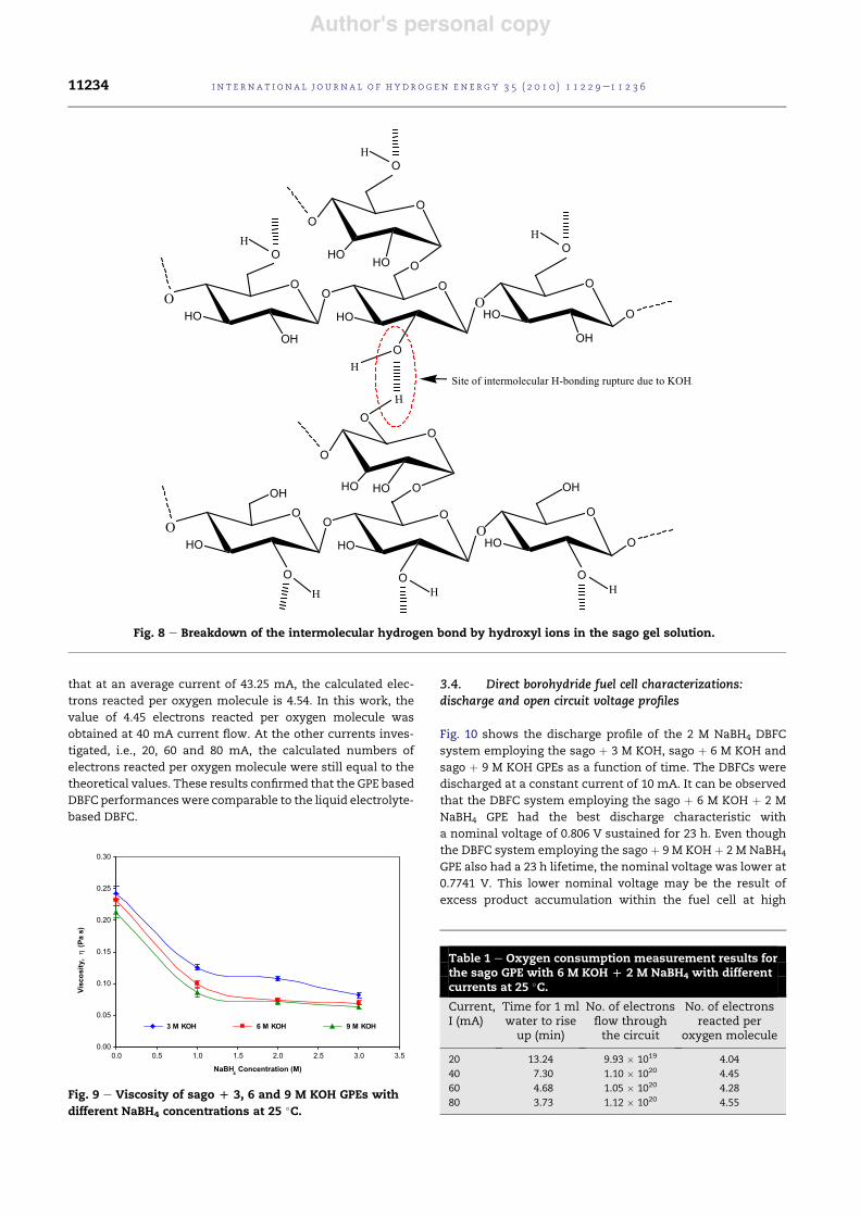
The viscosity of the sago GPE decreased dramatically to(0.262 % 0.018) Pa s when 1 M KOH was added, as shown inFig. 7. This decrease is attributed to the breakdown of inter-molecular hydrogen bonds of amylopectin and amylose by theabundant number of OH" ions from KOH, as illustrated inFig. 8. Rupturing of H-bond between H2O molecule of starchchain is more severe.
Meanwhile, adding higher concentrations of KOH did notvisibly affect the sago GPE viscosity; the viscosity remainedconstant up to 9M of KOH added. Apparently, the viscosity didnot limit the conductivity of the sago GPE significantly. Based
on the poly(methylmethacrylate) gel electrolytes [21,22], this
GPE can also be thought of as a conductive liquid encaged ina amylopectin structure with continuous free OH" conduction
paths available through it. As discussed earlier in Section 3.1,the direct addition of NaBH4 into the electrolyte system alsohad a small effect on the viscosity of the sago ! KOH GPE. Theviscosity behaviors of the sago! 3MKOH, sago! 6MKOHandsago ! 9 M KOH GPEs is shown in Fig. 9. For different KOHconcentrations, the viscosity of the GPE showed a decreasingpattern as higher concentrations of NaBH4 was added. Theoptimum viscosity of (0.074 % 0.003) Pa s was obtained for theGPE with a composition of sago ! 6 M KOH ! 2 M NaBH4. Theaddition of NaBH4 reduced the viscosity of the GPE system dueto the presence of H2. H2 is a gas with very low viscosity that
will definitely reduce the shear stress in the GPE system and,consequently, decrease the viscosity of the GPE.
3.3. Direct borohydride fuel cell characterizations:oxygen consumption
Table 1 shows the calculated values for the number of elec-trons involved in the cathode reaction at different appliedcurrents of 20, 40, 60 and 80mA. The calculated numbers werethe same as the theoretically estimated values at differentcurrents applied to the DBFC system. Verma et al. [23] reported
Fig. 5 e Hydrogen bond in amylopectin structure.
Fig. 6 e Viscosity of the pure sago GPE at 25 $C.Fig. 7 e Viscosity of sago GPEs with different KOHconcentrations at 25 $C.
i n t e r n a t i o n a l j o u r n a l o f h y d r o g e n en e r g y 3 5 ( 2 0 1 0 ) 1 1 2 2 9e1 1 2 3 6 11233
Author's personal copy
that at an average current of 43.25 mA, the calculated elec-trons reacted per oxygen molecule is 4.54. In this work, the
value of 4.45 electrons reacted per oxygen molecule wasobtained at 40 mA current flow. At the other currents inves-tigated, i.e., 20, 60 and 80 mA, the calculated numbers ofelectrons reacted per oxygen molecule were still equal to thetheoretical values. These results confirmed that the GPE basedDBFC performanceswere comparable to the liquid electrolyte-based DBFC.
3.4. Direct borohydride fuel cell characterizations:discharge and open circuit voltage profiles
Fig. 10 shows the discharge profile of the 2 M NaBH4 DBFCsystem employing the sago ! 3 M KOH, sago ! 6 M KOH andsago ! 9 M KOH GPEs as a function of time. The DBFCs weredischarged at a constant current of 10 mA. It can be observedthat the DBFC system employing the sago ! 6 M KOH ! 2 MNaBH4 GPE had the best discharge characteristic witha nominal voltage of 0.806 V sustained for 23 h. Even thoughthe DBFC system employing the sago ! 9 M KOH ! 2 M NaBH4
GPE also had a 23 h lifetime, the nominal voltage was lower at0.7741 V. This lower nominal voltage may be the result ofexcess product accumulation within the fuel cell at high
Fig. 8 e Breakdown of the intermolecular hydrogen bond by hydroxyl ions in the sago gel solution.
Fig. 9 e Viscosity of sago D 3, 6 and 9 M KOH GPEs withdifferent NaBH4 concentrations at 25 $C.
Table 1 e Oxygen consumption measurement results forthe sago GPE with 6 M KOH D 2 M NaBH4 with differentcurrents at 25 $C.
Current,I (mA)
Time for 1 mlwater to rise
up (min)
No. of electronsflow throughthe circuit
No. of electronsreacted per
oxygen molecule
20 13.24 9.93 & 1019 4.0440 7.30 1.10 & 1020 4.4560 4.68 1.05 & 1020 4.2880 3.73 1.12 & 1020 4.55
i n t e rn a t i o n a l j o u r n a l o f h y d r o g e n en e r g y 3 5 ( 2 0 1 0 ) 1 1 2 2 9e1 1 2 3 611234
Author's personal copy
reactant concentrations, which affected the performance. Anominal voltage of 0.743 V was obtained for the DBFC with the
sago! 3MKOH! 2MNaBH4 GPE, which lasted for 22 h. At lowKOH concentrations, reactant depletion may cause the DBFCsystem to have shorter lifetimes. From the results, differentKOH concentrations slightly affected the performance of theDBFC systems. The calculated discharge performance for theDBFCs employing the sago! 3MKOH! 2MNaBH4, sago! 6MKOH! 2 MNaBH4 and sago! 9 M KOH! 2 MNaBH4 GPEs were220, 230 and 230 mA h respectively. If the DBFCs werecontinuously suppliedwith fresh reactant and fuel, we believethat the discharge efficiencies could be improved as fuelcrossover issues could be reduced. Since this workwas carried
out in order to study the performance of DBFCs with a fixedamount of sago ! KOH ! NaBH4, the set up did not involvetanks for reactant and fuel stocks.
The voltage stability of the DBFC was investigated bymeasuring the VOC. Fig. 11 shows the VOC of the 2 M NaBH4
DBFCs employing the sago ! 3 M KOH, sago ! 6 M KOH andsago ! 9 M KOH GPEs. Without any load applied to the DBFCs,
the VOC were recorded every 60 min for 24 h at room
temperature. It can be seen that all the DBFCs demonstratedgood voltage stability. The DBFC employing the sago ! 6 MKOH GPE gave highest average VOC value of (0.926 % 0.009) V.DBFCs employing the sago ! 3 M KOH and sago ! 9 M KOHGPEs exhibited slightly lower VOC values of (0.882 % 0.006) Vand (0.904 % 0.004) V respectively. The stable voltage achievedby the DBFCsmay be explained by the good reactant tolerancewithin the system that was sufficient for 24 h of storage.Consequently, these results show that the DBFCs had gooddurabilities at room temperature and were able to satisfy therequirements as power sources.
3.5. Direct borohydride fuel cell characterizations: IeVand JeP curves
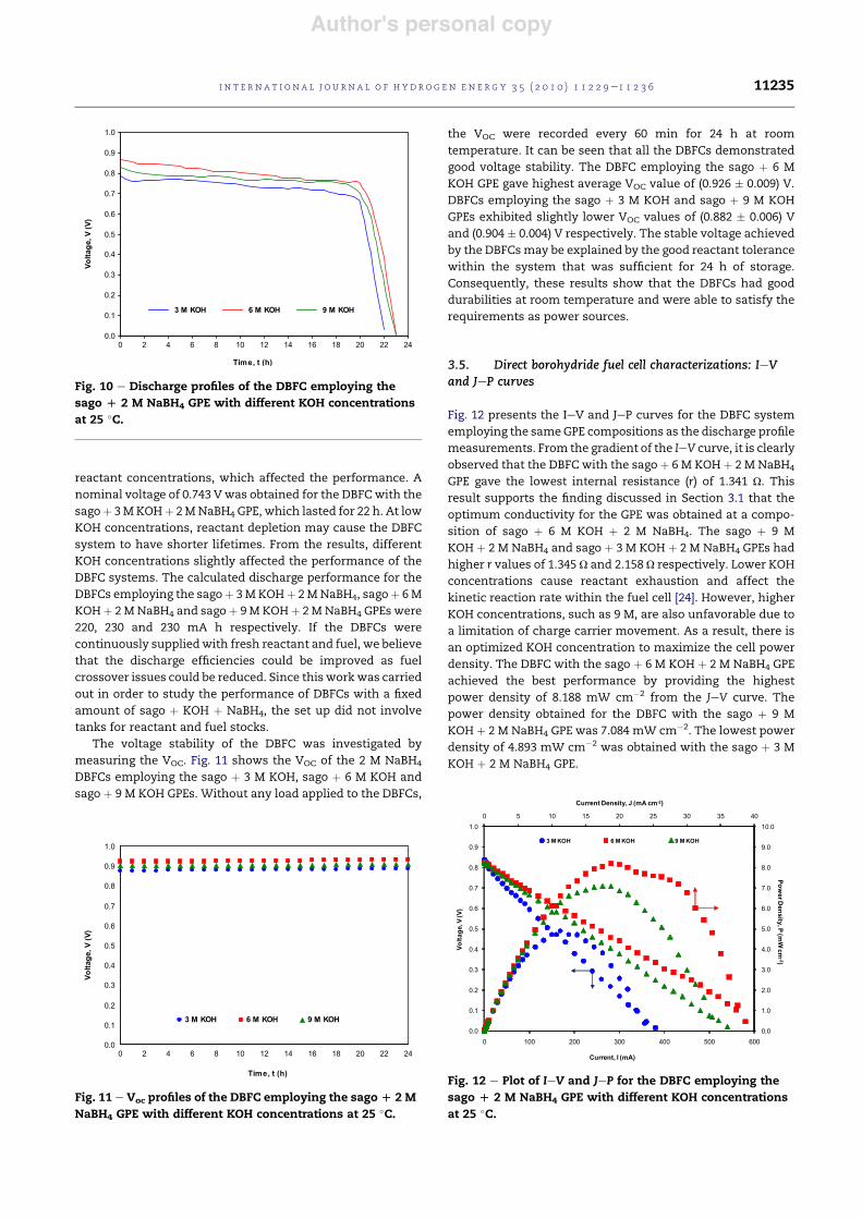
Fig. 12 presents the IeV and JeP curves for the DBFC systememploying the sameGPE compositions as the discharge profilemeasurements. From the gradient of the IeV curve, it is clearlyobserved that the DBFC with the sago ! 6 M KOH ! 2 M NaBH4
GPE gave the lowest internal resistance (r) of 1.341 U. This
result supports the finding discussed in Section 3.1 that theoptimum conductivity for the GPE was obtained at a compo-sition of sago ! 6 M KOH ! 2 M NaBH4. The sago ! 9 MKOH ! 2 M NaBH4 and sago ! 3 M KOH ! 2 M NaBH4 GPEs hadhigher r values of 1.345 U and 2.158 U respectively. Lower KOHconcentrations cause reactant exhaustion and affect thekinetic reaction rate within the fuel cell [24]. However, higherKOH concentrations, such as 9 M, are also unfavorable due toa limitation of charge carrier movement. As a result, there isan optimized KOH concentration to maximize the cell powerdensity. The DBFC with the sago ! 6 M KOH ! 2 M NaBH4 GPE
achieved the best performance by providing the highestpower density of 8.188 mW cm"2 from the JeV curve. Thepower density obtained for the DBFC with the sago ! 9 MKOH ! 2 M NaBH4 GPE was 7.084 mW cm"2. The lowest powerdensity of 4.893 mW cm"2 was obtained with the sago ! 3 MKOH ! 2 M NaBH4 GPE.
Fig. 10 e Discharge profiles of the DBFC employing thesago D 2 M NaBH4 GPE with different KOH concentrationsat 25 $C.
Fig. 11 e Voc profiles of the DBFC employing the sagoD 2 MNaBH4 GPE with different KOH concentrations at 25 $C.
Fig. 12 e Plot of IeV and JeP for the DBFC employing thesago D 2 M NaBH4 GPE with different KOH concentrationsat 25 $C.
i n t e r n a t i o n a l j o u r n a l o f h y d r o g e n en e r g y 3 5 ( 2 0 1 0 ) 1 1 2 2 9e1 1 2 3 6 11235

Author's personal copy
4. Conclusion
New GPEs based on sago ! KOH ! NaBH4 were prepared. Thebest GPE composition of sago ! 6 M KOH ! 2 M NaBH4 yieldeda high ionic conductivity of (0.270 % 0.005) S cm"1. Theviscosity of the GPE did not show major changes and therewere nomajor effects on the system. A DBFC utilizing this GPEsystem demonstrated good electrochemical capability. Theeffects of reactant and fuel concentration on the DBFC systemwere investigated through cell characterizations. The theo-
retical number of electrons reacted per oxygen molecule wasalso verified through oxygen consumption measurements.These results suggest that a sago-based GPE is suitable to beapplied in a DBFC for electrochemical device applications. Itsperformance is also comparable with a liquid-based DBFC.
Acknowledgements
A.J. would like to thank MOSTI for the NSF scholarship andUSM-RU-PRGS for their financial support via Grant (8031001).Z.A.A and A.A.M. wish to thank USM-RU for their financialsupport via Grant (811103).
r e f e r e n c e s
[1] Ma J, Choudhury NA, Sahai Y. A comprehensive review ofdirect borohydride fuel cells. Renew Sust Energ Rev 2010;14:183e99.
[2] Celik C, Boyaci San FG, Sarac HI. Effects of operationconditions on direct borohydride fuel cell performance.J Power Sources 2008;185:197e201.
[3] Antolini E, Gonzalez ER. Alkaline direct alcohol fuel cells.J Power Sources 2010;195:3431e50.
[4] Gyenge E, Atwan M, Northwood D. Electrocatalysis ofborohydride oxidation on colloidal Pt and Pt-alloys (Pt-Ir, Pt-Ni, and Pt-Au) and application for direct borohydride fuel cellanodes. J Electrochemical Soc 2006;153:A150e8.
[5] Fakioglu E, Yurum Y, Nejat Veziroglu T. A review of hydrogenstorage systems based on boron and its compounds. Int JHydrogen Energy 2004;29:1371e6.
[6] Celik C, San FGB, Sarac HI. Influences of sodium borohydrideconcentration on direct borohydride fuel cell performance. JPower Sources 2010;195:2599e603.
[7] Ma J, Liu Y, Liu Y, Yan Y, Zhang P. A membraneless directborohydride fuel cell using LaNiO3-catalysed cathode. FuelCells 2008;8:394e8.
[8] Jamard R, Salomon J, Martinent-Beaumont A, Coutanceau C.Life time test in direct borohydride fuel cell system. J PowerSources 2009;193:779e87.
[9] Liu BH, Li ZP, Arai K, Suda S. Performance improvement ofa micro borohydride fuel cell operating at ambientconditions. Electrochimica Acta 2005;50:3719e25.
[10] Cheng H, Scott K. Determination of kinetic parameters forborohydride oxidation on a rotating Au disk electrode.Electrochimica Acta 2006;51:3429e33.
[11] Lopes LVS, Dragunski DC, Pawlicka A, Donoso JP. Nuclearmagnetic resonance and conductivity study of starch basedpolymer electrolytes. Electrochim Acta 2003;48:2021e7.
[12] Mattos RI, Tambelli CE, Donoso JP, Pawlicka A. NMR study ofstarch based polymer gel electrolytes: humidity effects.Electrochim Acta 2007;53:1461e5.
[13] Yue Z, McEwen IJ, Cowie JMG. Novel gel polymer electrolytesbased on a cellulose ester with PEO side chains. Solid StateIonics 2003;156:155e62.
[14] Ng LS, Mohamad AA. Protonic battery based on a plasticizedchitosan-NH4NO3 solid polymer electrolyte. J Power Sources2006;163:382e5.
[15] Ng LS, Mohamad AA. Effect of temperature on theperformance of proton batteries based on chitosan-NH4NO3-EC membrane. J Membr Sci 2008;325:653e7.
[16] Seo JA, Koh JH, Roh DK, Kim JH. Preparation andcharacterization of crosslinked proton conductingmembranes based on chitosan and PSSA-MA copolymer.Solid State Ionics 2009;180:998e1002.
[17] Wu Q, Zhang J, Sang S. Preparation of alkaline solid polymerelectrolyte based on PVA-TiO2-KOHeH2O and itsperformance in ZneNi battery. J Phys Chem Solids 2008;69:2691e5.
[18] Mohamad AA, Arof AK. Effect of storage time on theproperties of PVA-KOH alkaline solid polymer electrolytesystem. Ionics 2006;12:57e61.
[19] Mohamad AA, Arof AK. Plasticized alkaline solid polymerelectrolyte system. Mater Lett 2007;61:3096e9.
[20] Srivastava N, Chandra S. Studies on a new proton conductingpolymer system: poly(ethylene succinate) ! NH4ClO4. EurPolym J 2000;36:421e33.
[21] Bohnke O, Frand G, Rezrazi M, Rousselot C, Truche C. Fastion transport in new lithium electrolytes gelled with PMMA.1. Influence of polymer concentration. Solid State Ionics1993;66:97e104.
[22] Deepa M, Sharma N, Agnihotry SA, Chandra R, Sekhon SS.Effect of mixed salts on the properties of gel polymericelectrolytes. Solid State Ionics 2002;148:451e5.
[23] Verma A, Jha AK, Basu S. Manganese dioxide as a cathodecatalyst for a direct alcohol or sodium borohydride fuel cellwith a flowing alkaline electrolyte. J Power Sources 2005;141:30e4.
[24] O’Hayre RP, Cha SW, Colella W, Prinz FB, editors. Fuel cellfundamentals. New York: John Wiley & Sons; 2006.
i n t e rn a t i o n a l j o u r n a l o f h y d r o g e n en e r g y 3 5 ( 2 0 1 0 ) 1 1 2 2 9e1 1 2 3 611236
Copyright © 2022 FDOKUMEN