Relative Energetics at the Semiconductor/Sensitizing Dye/Electrolyte Interface
10
Subscriber access provided by Flinders University Library The Journal of Physical Chemistry B is published by the American Chemical Society. 1155 Sixteenth Street N.W., Washington, DC 20036 Article Relative Energetics at the Semiconductor/Sensitizing Dye/Electrolyte Interface Arie Zaban, Suzanne Ferrere, and Brian A. Gregg J. Phys. Chem. B, 1998, 102 (2), 452-460 • DOI: 10.1021/jp972924n Downloaded from http://pubs.acs.org on December 4, 2008 More About This Article Additional resources and features associated with this article are available within the HTML version: • Supporting Information • Links to the 9 articles that cite this article, as of the time of this article download • Access to high resolution figures • Links to articles and content related to this article • Copyright permission to reproduce figures and/or text from this article
Transcript of Relative Energetics at the Semiconductor/Sensitizing Dye/Electrolyte Interface

Subscriber access provided by Flinders University Library
The Journal of Physical Chemistry B is published by the American Chemical Society.1155 Sixteenth Street N.W., Washington, DC 20036
Article
Relative Energetics at the Semiconductor/Sensitizing Dye/Electrolyte InterfaceArie Zaban, Suzanne Ferrere, and Brian A. Gregg
J. Phys. Chem. B, 1998, 102 (2), 452-460 • DOI: 10.1021/jp972924n
Downloaded from http://pubs.acs.org on December 4, 2008
More About This Article
Additional resources and features associated with this article are available within the HTML version:
• Supporting Information• Links to the 9 articles that cite this article, as of the time of this article download• Access to high resolution figures• Links to articles and content related to this article• Copyright permission to reproduce figures and/or text from this article
Relative Energetics at the Semiconductor/Sensitizing Dye/Electrolyte Interface
Arie Zaban,* ,† Suzanne Ferrere, and Brian A. Gregg*National Renewable Energy Laboratory, 1617 Cole BouleVard, Golden, Colorado 80401-3393
ReceiVed: September 8, 1997; In Final Form: NoVember 6, 1997
Chemical oxidation, spectro-electrochemical reduction, and potential-dependent photoluminescence wereemployed to investigate changes in the redox potential of eight different adsorbed sensitizing dyes relative tothe potentials of the semiconductor and the electrolyte solution. The redox potentials of the investigateddyes were pH-independent in solution but developed a pH dependence that varied between 21 and 53 mV perpH unit upon adsorption to an oxide surface. Electrochemical experiments show that the apparent redoxpotential of the dye could also be influenced by an external bias applied to the electrode. The adsorption-induced potential changes were found to depend on both the dye structure and the electrolyte composition.A proposed model that considers the position of the specifically adsorbed dye relative to the ionic doublelayer at the electrode/electrolyte interface explains these results qualitatively. When the dye is mostly insidethe double layer, its potential will tend to follow changes in the semiconductor potential; when it is mostlyoutside, its potential will be almost independent of the semiconductor. The fact that the potential of thesensitizing dye is not fixed relative to either the semiconductor or the electrolyte solution has importantimplications for the understanding and optimization of dye-sensitized cells.
Introduction
Sensitization of wide band gap semiconductors with organicand inorganic dyes is currently of great interest in solar energyconversion systems.1 Dye-sensitized solar cells that convertlight to electrical energy at efficiencies as high as 10%,2,3 andother applications like self-powered electrochromic windows4
and light-emitting diodes5 have been reported. Studies concern-ing the fundamental understanding of the dye-TiO2 system6-10
and new materials like other high surface area semiconduc-tors11,12 and new sensitizers13-16 have appeared recently. Theincreasing research effort toward higher efficiencies and solid-state versions of these cells17-21 is evident from the literature.The dye-sensitization process is based on charge separation
at the semiconductor/dye/electrolyte interface.22 Fast electroninjection from the dye to the semiconductor occurs uponillumination followed by hole transfer to the electrolyte solution(regeneration of the dye).22-24 Many factors, such as thedistance between the dye and the semiconductor,25 the type ofbond that connects them26,27 and the properties of the redoxcouple in the electrolyte solution,28 influence the efficiency ofthe process.Perhaps the most fundamental property that should be
considered during the design of such cells is the relative energiesat the semiconductor/dye/electrolyte interface. The dye excited-state oxidation potential has to be more negative than thesemiconductor conduction band potential to enable the electroninjection, and the oxidation potential of the dye must be morepositive than the redox couple in the electrolyte solution toprovide the driving force for the hole transfer.22,29 Within theselimits, the cell performance is affected by the exact position ofthe relative potentials. A change in either of the two drivingforces impacts both the short circuit photocurrent and the opencircuit photovoltage of the cell.22,30 Therefore, optimization of
the dye-sensitized solar cells must involve considerationsregarding the semiconductor, dye, and electrolyte energetics.29
All four potentials that affect the semiconductor/dye/electrolyte interface can be measured separately: the conductionband potential of the high surface area semiconductor can beresolved by measurements of its absorption31 or reflection32
during a potential sweep, the oxidation potential of the dye insolution and the potential of the redox couple can be measuredby cyclic voltammetry,33 and the dye’s excited-state potentialcan be estimated from its oxidation potential and the excited-state energy.13,22 However, measurements of these potentialsunder working cell conditions, i.e., when the dye is adsorbedonto the semiconductor and the electrolyte solution is present,are more complicated. The complexity arises mostly from thelimited electrochemical window resulting from the insulatingnature of the TiO2 at positive bias34 and the tendency of thedye to desorb at negative bias.6 It is, therefore, usually assumedthat the potentials measured individually still pertain when thecomplete solar cell is assembled.In a previous paper35we reported measurements of the redox
potential of one ruthenium-based dye adsorbed on TiO2 as afunction of solution pH. The redox potential was determinedby chemical oxidation with aqueous bromine solution. Wefound that, upon adsorption onto the TiO2, the redox potentialof the dye became pH-dependent, changing by 53 mV per pHunit, although the potential of the dye in solution was indepen-dent of pH. The pH sensitivity of the redox potential inducedby adsorption onto TiO2 was assumed to be correlated to thewell-known movement of the TiO2 conduction band by 59 mVper pH unit.36,37 However, at that point we were unable toprovide a definitive mechanism for this process.In this paper, a more comprehensive study of the effect of
adsorption on the redox potential of the dye is reported. Theredox potential was investigated by chemical oxidation, spectro-electrochemical reduction, and potential dependent photolumi-nescence. Five ruthenium dyes, two phthalocyanine dyes, and
† Current address: Department of Chemistry, Bar-Ilan University, RamatGan 52900, Israel.
452 J. Phys. Chem. B1998,102,452-460
S1089-5647(97)02924-6 CCC: $15.00 © 1998 American Chemical SocietyPublished on Web 01/08/1998

a perylene dye were investigated. The six dyes tested for pHdependence exhibited a pH-dependent redox potential inducedby adsorption to TiO2 or to insulating Al2O3. The magnitudeof the pH sensitivity varied between 21 and 53 mV per pH unitdepending on the dye structure. Electrochemical experimentsshowed that the redox potential of the dye was also affected byan externally applied bias. This sensitivity to pH and electricalbias depends both on the ability of electrolyte ions to penetratethe dye layer and on the dye structure. The crucial parameteris the position of the specifically adsorbed dye relative to theionic double layer (Helmholtz and diffuse layers). The mech-anism by which the adsorption affects the redox potential, andthe importance of these findings to the design and understandingof dye-sensitized systems, will be discussed.
Experimental
Materials and Methods. 2,2′-bipyridine, 4,4′-dimethyl-2,2′-bipyridine, 3,4,9,10-perylenetetracarboxylic acid dianhydride,and RuCl3‚3H2O were obtained from Aldrich. 4,4′-Dicarboxylicacid-2,2′-bipyridine was obtained from Alfa/Aesar. All othersynthetic starting materials were reagent or ACS grade.Preparation of Pyridyl Ligands. 1,2-bis[4′-methyl-2,2′-
bipyridyl-4-yl]ethane,38 4,4′-bis(bromomethyl)-2,2′-bipyridine,39and 4-bromo-2,2′-bipyridine40 were prepared via publishedprocedures. 4,4′-Bis(diethyl methylphosphonate)-2,2′-bipyridinewas prepared from 4,4′-bis(bromomethyl)-2,2′-bipyridine ac-cording to a method used by Hupp41 and chromatographed onsilica gel using 10% acetone in dichloromethane as eluent.4-Bromo-2,2′-bipyridine was converted to 4-diethyl phospho-nate-2,2′-bipyridine using the procedure of Hirao et al.42
4,4′,5,5′-Tetramethyl-2,2′-bipyridine was a gift of Professor C.Michael Elliott, prepared from 3,4-lutidine.43 4′-Diethyl phos-phonate-2,2′:6′,2′′-terpyridine was prepared via the same three-step sequence employed by Gra¨tzel.42,44,45
[RuII (4′-phosphonic acid-2,2′:6′,2′′-terpyridine)(1,2-bis[4′-methyl-2,2′-bipyridyl-4-yl]ethane)(CN)] (Dye 1). [Ru(4′-diethyl phosphonate-2,2′:6′,2′′-terpyridine)(Cl)3] was preparedvia a modification of a literature procedure.46 In a typicalpreparation, 800 mg of RuCl3‚3H2O (3.07 mmol) was dissolvedin 175 mL of absolute ethanol and degassed with N2. To thesolution was added 1.13 g (3.05 mmol) of 4′-diethyl phospho-nate-2,2′:6′,2′′-terpyridine, and the reaction mixture refluxed for5 h under N2. The brown solution was allowed to cool to roomtemperature and the resulting copper-colored precipitate wascollected by vacuum filtration. The product was rinsed with 3× 25 mL portions of ethanol and dried under vacuum. A typicalyield was 1.3 g (74%). Subsequently, [Ru(4′-diethyl phospho-nate-2,2′:6′,2′′-terpyridine)(1,2-bis(4′-methyl-2,2′-bipyridyl-4-yl)ethane)(Cl)] was prepared by reaction of 3.0 g of [1,2-bis(4′-methyl-2,2′-bipyridyl-4-yl)ethane] (8.2 mmol) and 900 mg of[Ru(4′-diethylphosphonate-2,2′:6′,2′′-terpyridine)(Cl)3] (1.56mmol) in 100 mL of dimethylformamide. The mixture wasbrought to reflux under N2, and within 15 min the solution wasa deep crimson color. Refluxing was continued for 5 h, afterwhich time all of the dimethylformamide was removed by rotaryevaporation. The product mixture was redissolved in water andfiltered to remove unreacted ligand. The pH of the aqueoussolution was brought to 1 with concentrated hydrochloric acid,and then refluxed overnight to effect hydrolysis of the phos-phonate ester groups, yielding [RuII(4′-phosphonic acid-2,2′:6′,2′′-terpyridine)(1,2-bis[4′-methyl-2,2′-bipyridyl-4-yl]ethane)-(Cl)]. The complex could be isolated from water as thezwitterionic “[RuII(4′-P(O)(OH)(O-)-2,2′:6′,2′′-terpyridine)(1,2-bis[4′-methyl-2,2′-bipyridyl-4-yl]ethane)(Cl-)]” and was then
reacted overnight with 1.0 g of NaCN (20 mmol) in∼60 mLof refluxing dimethylformamide containing 20 mL of 0.1 MNaOH. After rotary evaporation of all solvent, the complexwas redissolved in water and the pH lowered to∼2 by theaddition of dilute trifluoromethanesulfonic acid. The precipi-tated product was collected by filtration and dried under vacuum.[RuII (4′-phosphonic acid-2,2′:6′,2′′-terpyridine)(4,4′-di-
methyl-2,2′-bipyridine)(CN)] (Dye 2). This complex wasprepared in identical fashion to dye 1, except that in theintermediate step to prepare [Ru(4-diethylphosphonate-2,2′:6′,2′′-terpyridine)(4,4′-dimethyl-2,2′-bipyridine)(Cl)] 153.8 mgof [Ru(4′-diethylphosphonate-2,2′:6′,2′′-terpyridine)(Cl)3] (0.267mmol) and 65.2 mg of 4,4′-dimethyl-2,2′-bipyridine (0.35 mmol)were used.[RuII (4-phosphonic acid-2,2′-bipyridine) 2(1,2-bis[4′-meth-
yl-2,2′-bipyridyl-4-yl]ethane)] (Dye 3). [RuII(4-diethyl phos-phonate-2,2′-bipyridine)2Cl2] was prepared according to aliterature preparation47 using 483 mg of 4-diethyl phosphonate-2,2′-bipyridine (1.65 mmol), 216 mg of RuCl3‚3H2O (0.825mmol), and 233 mg of LiCl (5.5 mmol). The product wasconverted to [RuII(4-phosphonic acid-2,2′-bipyridine)2Cl2 byrefluxing overnight in 0.5 M HCl. The product was refluxedin dimethylformamide containing 853 mg of 1,2-bis[4′-methyl-2,2′-bipyridyl-4-yl]ethane (2.3 mmol) for approximately 16 h.The dimethylformamide was rotary evaporated, and the reactionmixture was redissolved in water and filtered to remove excessligand. The aqueous portion was rotary evaporated to drynessand then dried under vacuum.[RuII (4,4′-bis(methylphosphonic acid)-2,2′-bipyridine) 2-
(4,4′,5,5′-tetramethyl-2,2′-bipyridine)] (Dye 4). [RuII(4,4′-bis[diethyl methylphosphonate]-2,2′-bipyridine)2Cl2] was pre-pared via modification of a literature preparation,47 using 305mg of 4,4′-bis(diethyl methylphosphonate)-2,2′-bipyridine (0.669mmol), 87.0 mg of RuCl3‚3H2O (0.333 mmol), and 94 mg ofLiCl (2.2 mmol). Subsequently, 100.3 mg of [RuII(4,4′-bis[diethyl methylphosphonate]-2,2′-bipyridine)2Cl2] (0.0925mmol) and 39 mg of 4,4′,5,5′-tetramethyl-2,2′-bipyridine (0.20mmol) in 3 mL of dimethylformamide and 2 mL of 0.1 M KOHwere refluxed for 6 h under an argon atmosphere. The reactionmixture was rotary evaporated to dryness, redissolved in water,and made neutral by the addition of dilute sulfuric acid. Excess,unreacted 4,4′,5,5′-tetramethyl-2,2′-bipyridine was filtered fromthe aqueous solution; the pH was made to∼1 and the solutionrefluxed overnight to ensure hydrolysis of the phosphonategroups. All attempts to crash the complex out of aqueoussolution via pH manipulation were unsuccessful. Instead, thepH was made neutral by addition of dilute NaOH and thesolution rotary evaporated to dryness. Redissolution in ethanolallowed the filtering out of excess salts.M-4,4′,4′′,4′′′-tetracarboxyphthalocyanines (Dyes 5 and 6).
FeIII -4,4′,4′′,4′′′-tetracarboxyphthalocyanine (dye 6) was pre-pared according to Shirai et al.48 MgII-4,4′,4′′,4′′′-tetracarboxy-phthalocyanine (dye 5) was prepared similarly; however,magnesium acetate was used in place of the metal chloride.Purity of the phthalocyanines was assessed via absorptionspectra and cyclic voltammetry.3,4,9,10-Perylenedihydroxamic Acid Dianhydride (Dye 7).
The dye was prepared by variation of the method employed byFord to prepare the di(glycyl)imide derivative.49 3,4,9,10-Perylenetetracarboxylic acid dianhydride (260 mg, 0.663 mmol)was suspended in∼25 mL of dimethyl sulfoxide and heated to90 °C. Hydroxylamine hydrochloride (1.1 g, 16 mmol) andKOH (900 mg, 16 mmol) dissolved in∼20 mL of water weresubsequently added to the hot suspension. A condenser was
Redox Potential of Sensitizing Dyes J. Phys. Chem. B, Vol. 102, No. 2, 1998453
attached, and heating was continued for 3 h. The darkprecipitate was collected on a 0.45µm filter and then heated in0.5 M HCl. The acidified precipitate was again collected andrinsed with water. The product was purified by recrystallizationin methanol and dried under vacuum. Although the initial yieldis high (>90%), due to its sparing solubility in methanol, yieldsafter purification are much lower (∼10%). Its identity wasconfirmed by absorption and infrared spectra.[RuII (4,4′-dicarboxylic acid-2,2′-bipyridine) 2(4,4′-dimethyl-
2,2′-bipyridine)][PF 6]2 (Dye 8). [RuII(4,4′-dicarboxylic acid-2,2′-bipyridine)2Cl2] was prepared according to Meyer47 em-ploying 913.3 mg of 4,4′-dicarboxylic acid-2,2′-bipyridine(3.740 mmol), 488.4 mg of RuCl3‚3H2O (1.871 mmol), and 529mg of LiCl (12.5 mmol). Next, 409 mg of [RuII(4,4′-dicarboxylic acid-2,2′-bipyridine)2Cl2] (0.62 mmol) was reactedwith 136 mg of 4,4′-dimethyl-2,2′-bipyridine (0.739 mmol) in∼50 mL dimethylformamide containing 10 mL of 0.1 M NaOH.The solvent was rotary evaporated and the reaction mixturedissolved in water; the pH was made neutral by the addition ofdilute trifluoromethanesulfonic acid, and excess ligand wasfiltered off. The pH was lowered further to pH 2; an aqueous,saturated solution of ammonium hexafluorophosphate wasadded. There was only partial precipitation of the complex asthe PF6- salt; the precipitated portion was collected by vacuumfiltration, rinsed with water, and dried under vacuum.TiO2 Electrodes. Conductive glass substrates (Libby Owens
Ford, 10Ω/square F-SnO2) were cleaned by overnight immer-sion in a solution of KOH in 2-propanol, rinsed with deionizedwater, and dried in a nitrogen stream. The TiO2 colloidalsuspension (preparation reported elsewhere35) was spread overthe substrate with a glass rod using adhesive tape as spacers.The films were fired at 450°C for 45 min in air, resulting in analmost transparent film. The films thickness was 4µm in thechemical oxidation experiments and 1.5µm in the electrochemi-cal experiments. The dyes were adsorbed by immersing theelectrodes overnight in a 0.5 mM aqueous or acetonitrile solutionof the dye.Measurements. Electrochemical measurements were per-
formed with a PAR 173 potentiostat in a three-electrodearrangement. Potentials are reported vs SCE. Absorptionspectra were measured with a HP 8453 spectrophotometer usingan undyed nanocrystalline TiO2 electrode as a reference.Fluorescence emission spectra were measured with an AmincoBowman AB2 Spectrofluorometer employing a front faceelectrochemical cell. Both the spectro-electrochemical reductionand the potential-dependent photoluminescence experimentswere done in dry conditions using a sealed cell that was loadedin a nitrogen atmosphere glovebox. The electrolyte solutionwas 0.1 M LiClO4 or 0.1 M tetrabutylammonium hexafluoro-phosphate (TBAPF6) in dry acetonitrile (Burdick & Jackson,distilled over calcium hydride). The reference electrode forthese experiments was a silver wire calibrated vs ferrocene/ferrocenium and reported vs SCE.The oxidation or reduction potentials of the different ruthenium-
based dyes in solution were determined by cyclic voltammetry.The experiments used a platinum or glassy carbon workingelectrode, an SCE reference electrode, and a platinum counterelectrode. In one case (dye 5) the oxidation potential wasdetermined by spectrochemical titration. An I2 oxidizingsolution was added to the dye solution, and the fraction ofoxidized dye was determined from the change in the solutionabsorption spectrum. A plot of the fraction of oxidized dye asa function of the solution potential yielded the oxidationpotential.
The chemical oxidation experiments were carried out usingan aqueous solution of either Br2 or I2 as the oxidizing solution.The concentration of the oxidizing species (Br2 or I2) in thesolution was 104 times higher than the amount of dye on thefilm, so the change in potential of the solution resulting fromoxidation of the dye was negligible. The fraction of dyeoxidized in each experiment was fitted to the potential of thespecific oxidizing solution, measured both before and after thedye oxidation. A stock solution of 20 mM Br2 or I2 in HClO4
was made at pH 2, and the pH was adjusted by addition ofNaOH. The ionic strength was approximately constant through-out the pH range. Control experiments at higher ionic strengthsup to 200 mM showed no change in the fraction of oxidizeddye with increasing ionic strength.
Results and Discussion
Cyclic voltammetry was employed to measure the oxidationpotentials of the different ruthenium dyes in solution as afunction of solution pH (cyclic voltammograms of dye 1 werereported in ref 35). The oxidation potential of the phthalocya-nine dye (dye 5) as a function of the solution pH was resolvedby spectrochemical titration experiments (see ExperimentalSection). The formal potentials of the different dyes in solutionare listed in Table 1. The electron-transfer processes in all casesare chemically reversible and the dyes are stable in bothoxidation states. Over the pH range of our experiments (pH2-8), the oxidation potentials of all dyes in solution were foundto be independent of pH.Once adsorbed to the nanocrystalline TiO2 film, the dyes
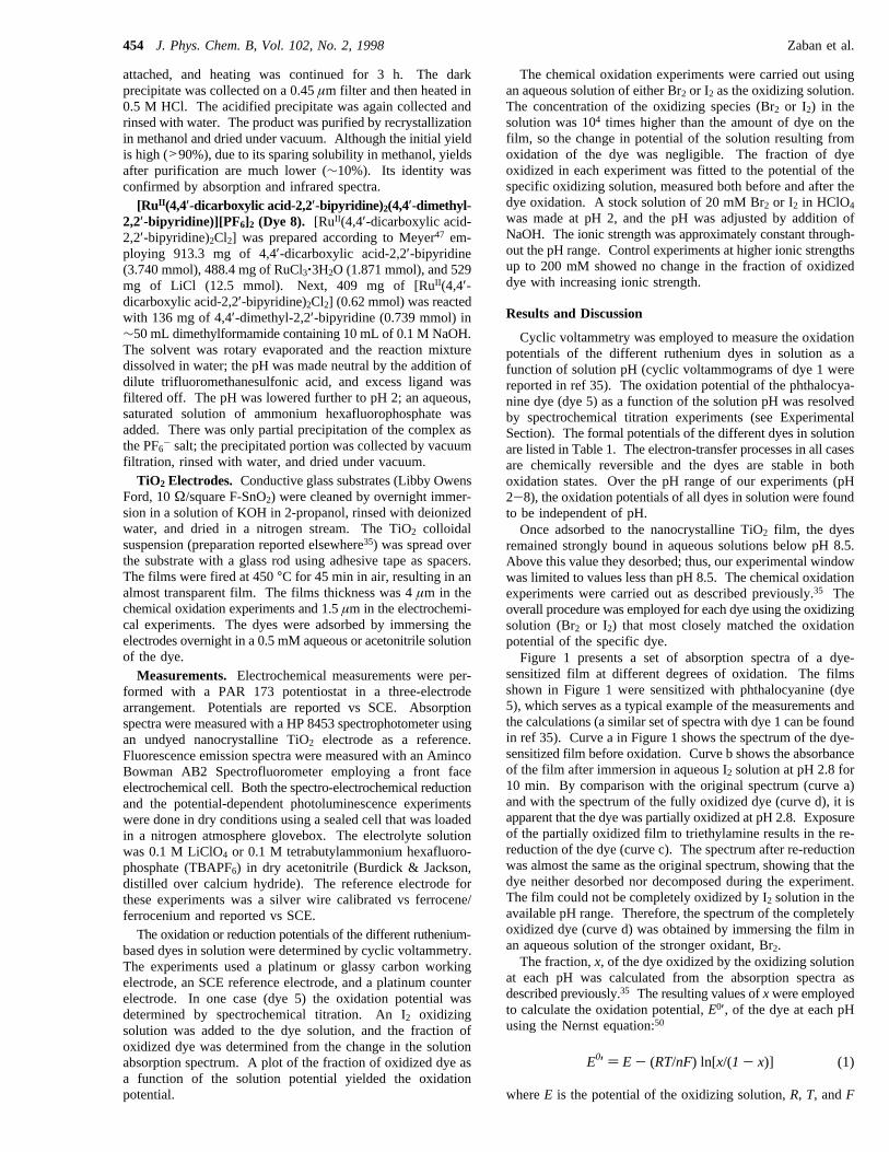
remained strongly bound in aqueous solutions below pH 8.5.Above this value they desorbed; thus, our experimental windowwas limited to values less than pH 8.5. The chemical oxidationexperiments were carried out as described previously.35 Theoverall procedure was employed for each dye using the oxidizingsolution (Br2 or I2) that most closely matched the oxidationpotential of the specific dye.Figure 1 presents a set of absorption spectra of a dye-
sensitized film at different degrees of oxidation. The filmsshown in Figure 1 were sensitized with phthalocyanine (dye5), which serves as a typical example of the measurements andthe calculations (a similar set of spectra with dye 1 can be foundin ref 35). Curve a in Figure 1 shows the spectrum of the dye-sensitized film before oxidation. Curve b shows the absorbanceof the film after immersion in aqueous I2 solution at pH 2.8 for10 min. By comparison with the original spectrum (curve a)and with the spectrum of the fully oxidized dye (curve d), it isapparent that the dye was partially oxidized at pH 2.8. Exposureof the partially oxidized film to triethylamine results in the re-reduction of the dye (curve c). The spectrum after re-reductionwas almost the same as the original spectrum, showing that thedye neither desorbed nor decomposed during the experiment.The film could not be completely oxidized by I2 solution in theavailable pH range. Therefore, the spectrum of the completelyoxidized dye (curve d) was obtained by immersing the film inan aqueous solution of the stronger oxidant, Br2.The fraction,x, of the dye oxidized by the oxidizing solution
at each pH was calculated from the absorption spectra asdescribed previously.35 The resulting values ofxwere employedto calculate the oxidation potential,E0′, of the dye at each pHusing the Nernst equation:50
whereE is the potential of the oxidizing solution,R, T, andF
E0′ ) E- (RT/nF) ln[x/(1- x)] (1)
454 J. Phys. Chem. B, Vol. 102, No. 2, 1998 Zaban et al.

are the Boltzmann constant, the temperature, and the Faradayconstant, respectively, andn is the number of electrons involved
in the oxidation process. For all dyes a linear correlationbetween the oxidation potential of the adsorbed dye (E0′) and
TABLE 1: pH-Dependent Redox Potential Induced in Sensitizing Dyes by Specific Adsorption onto Oxide Surfaces
Redox Potential of Sensitizing Dyes J. Phys. Chem. B, Vol. 102, No. 2, 1998455
the pH of the oxidizing solution was found. In Figure 2, forexample, the oxidation potential of dye 5 when adsorbed ontoTiO2 is plotted as a function of the pH of the oxidizing solution.As the pH increases,E0′ decreases by 20.6( 1.8 mV per pHunit, in contrast to the pH-independent oxidation potential whendye 5 is dissolved in solution. The linear correlation betweenE0′ of the adsorbed dye 5 and the pH predicts that at pH 0 theoxidation potential will be shifted 83( 13 mV positive of itssolution value. The corresponding values for all dyes studied(dyes 1 through 6) are presented in Table 1. The oxidationpotentials of all six dyes became pH-sensitive upon adsorptiononto TiO2, the dependence varying between 21 and 53 mV perpH unit.In a previous paper,35 we proposed two possible mechanisms
for the induced pH dependence. Both mechanisms suggestedthat the induced pH dependence was related to the well-known59 mV per unit pH shift of the flat band potential of oxidesemiconductors.36,37 The flat band potential shift was proposedto affect the adsorbed dye (i) by the strong electronic interactionbetween the dye and the TiO2 that is necessary to achieve thehigh quantum efficiencies (>80%) for electron injection ob-served in these systems or (ii) by the influence of theelectrostatic field caused by the adsorption of ions (H+ and OH-)on the semiconductor surface.Chemical oxidation experiments on dye 1 adsorbed onto high
surface area aluminum oxide films were performed in order tocheck the validity of the first mechanism. Insulating aluminumoxide was chosen to exclude the possibility of electronicinteractions between the dye and the substrate. The conductionband of Al2O3 is much too far negative to interact with the dye.The pH dependence of dye 1 on Al2O3 was identical to that onTiO2 (Table 1). These results clearly indicate that electronicinteractions between the dye and the oxide surface are notnecessary to induce the pH dependence.The second mechanism, on the other hand, is consistent with
the results reported in Table 1. The influence of an electric
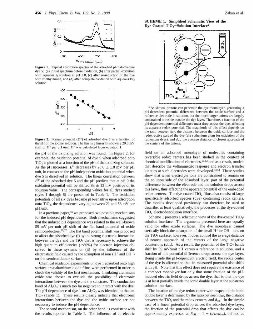
field on an adsorbed monolayer of molecules containingreversible redox centers has been studied in the context ofchemical modification of electrodes,51,52and as a result, modelsthat describe the voltammetric response and electron transferkinetics at such electrodes were developed.53,54 These studiesshow that when electrolyte ions are constrained to remain onthe solution side of the adsorbed layer, part of the potentialdifference between the electrode and the solution drops acrossthis layer, thus affecting the apparent potential of the embeddedredox centers. The dye-coated TiO2 films also consist of largespecifically adsorbed species (dye) containing redox centers.The models developed previously can therefore be used todescribe, at least qualitatively, the processes at the dye-coatedTiO2 electrode/solution interface.Scheme 1 presents a schematic view of the dye-coated TiO2/
solution interface. The arguments presented here are equallyvalid for other oxide surfaces. The dye monolayer cannotsterically block the adsorption of the small H+ or OH- ions onthe TiO2 surface; however, it does control the average distanceof nearest approach of the centers of the large negativecounterions (dion). As a result, the potential of the TiO2 bandsshift by 59 mV/unit pH versus a reference in solution, and afraction of this potential difference drops across the dye layer.Being inside the pH-dependent electric field, the redox centerof the dye is affected so that its measured potential also shiftswith pH. Note that this effect does not require the existence ofa compact monolayer but only that some fraction of the pH-induced electric field drops across the dye, that is, that the dyeis at least partially inside the ionic double layer at the substrate/solution interface.The location of the dye redox center with respect to the ionic
double layer is determined by the ratio betweendRO, the distancebetween the TiO2 and the redox centers, anddion. In the simplecase of a linear potential drop across the adsorbed dye layer,the fraction of the potential drop that affects the dye can beapproximately expressed asSpH ) 1 - (dRO/dion), defined as
Figure 1. Typical absorption spectra of the adsorbed phthalocyaninedye 5: (a) initial spectrum before oxidation, (b) after partial oxidationwith aqueous I2 solution at pH 2.8, (c) after re-reduction of the dyewith triethylamine, and (d) after complete oxidation with aqueous Br2
solution.
Figure 2. Formal potential (E0′) of adsorbed dye 5 as a function ofthe pH of the iodine solution. The line is a linear fit showing 20.6 mVshift of E0′ per pH unit.E0′ was calculated from equation 1.
SCHEME 1: Simplified Schematic View of theDye-Coated TiO2-Solution Interfacea
a As shown, protons can penetrate the dye monolayer, generating apH-dependent potential difference between the oxide surface and areference electrode in solution, but the much larger anions are largelyconstrained to reside outside the dye layer. Therefore, a fraction of thepH-dependent potential difference must drop across the dye, affectingits apparent redox potential. The magnitude of this affect depends onthe ratio betweendRO, the distance between the oxide surface and theredox-active part of the dye (the ruthenium atom for oxidation of theruthenium dyes), anddion, the average distance of closest approach ofthe centers of the anions.
456 J. Phys. Chem. B, Vol. 102, No. 2, 1998 Zaban et al.
the sensitivity. The maximum potential shift of 59 mV/unitpH occurs whenSpH ) 1 and may approach zero whenSpH )0. High Smeans that the redox potential of the dye closelyfollows the flat band potential of the semiconductor, while lowSmeans it is almost independent of changes in the semiconduc-tor potential. The exact electric field distribution at this interfacedepends on a number of factors such as the dielectric propertiesof the solution and the dye, the geometry of the surface, thedye coverage, the identity and concentration of the electrolyteions, etc. The potential drop across the dye layer is notnecessarily linear, and the linear illustration in Scheme 1 is justthe simplest case. Qualitatively, however,SpH will be employedbelow to explain the variation in pH dependence between thedifferent dyes.According to the proposed model (Scheme 1), the sensitivity
of the dye redox potential to pH-induced changes in thesemiconductor potential depends on the molecular structure ofthe dye, other factors being constant. To check the validity ofthe model, the sensitivities of dye 1 and dye 2, that differ onlyby the additional outboard bipyridine linked to dye 1 (Table1), were measured. The distances between the redox center ofthese dyes (the ruthenium atom in the case of oxidation of RuII
to RuIII ) and the TiO2 (dRO) should be similar, as both dyesadsorb to the TiO2 through their phosphonic acid group.However,dion of dye 1 is expected to be larger thandion of dye2, because of the additional bipyridine. Therefore, theSpH value(1 - dRO/dion) of dye 1 should be larger than theSpH value ofdye 2. The measured sensitivity to pH of dye 1 (54 mV/pH,Table 1) is, in fact, higher than the measured sensitivity of dye2 (43 mV/pH), in agreement with the proposed model.Precise simulation of the potential distribution across the dye
layer and accurate calculations of eitherdRO or dion are beyondthe scope of this work. But a qualitative discussion of the pHsensitivities of the various dyes is possible. The reason thatdye 1 has a higherSpH value than dye 2 was just discussed.Both dye 3 and dye 1 show a large pH dependence, probablydue to the size of the external bipyridine ligand that increasesthe nearest approach distance of the negative ions (dion). Thelower sensitivity of dye 4 compared to dye 2 may result fromthe following: the additional methyl on the phosphonic acidbonding group of dye 4 that decreasesSpH, the different bondingof dye 4 to the TiO2 (through 2 to 3 bonding groups), or theeffect of the unbound, ionizable phosphonic acid group on thepotential distribution across the dye layer. The adsorbedphthalocyanine dyes (dyes 5 and 6) have the smallest inducedpH dependence. These dyes probably adhere to the TiO2
through all four carboxylic acid groups in a flat configuration.Their redox center is delocalized over the whole molecule ratherthan being localized on a specific atom. The small sensitivityto the pH-induced band edge movement measured for these dyesmay indicate thatdRO anddion of the phthalocyanine dyes arealmost the same.Additional support for the proposed description of the dye-
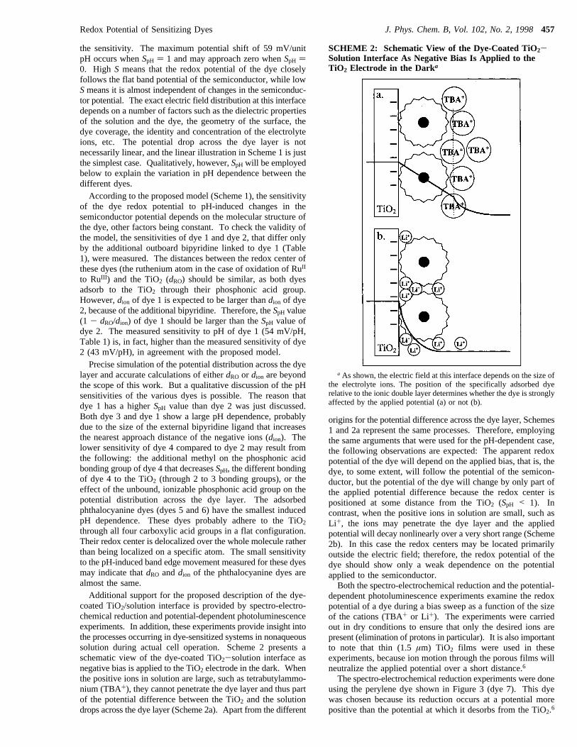
coated TiO2/solution interface is provided by spectro-electro-chemical reduction and potential-dependent photoluminescenceexperiments. In addition, these experiments provide insight intothe processes occurring in dye-sensitized systems in nonaqueoussolution during actual cell operation. Scheme 2 presents aschematic view of the dye-coated TiO2-solution interface asnegative bias is applied to the TiO2 electrode in the dark. Whenthe positive ions in solution are large, such as tetrabutylammo-nium (TBA+), they cannot penetrate the dye layer and thus partof the potential difference between the TiO2 and the solutiondrops across the dye layer (Scheme 2a). Apart from the different
origins for the potential difference across the dye layer, Schemes1 and 2a represent the same processes. Therefore, employingthe same arguments that were used for the pH-dependent case,the following observations are expected: The apparent redoxpotential of the dye will depend on the applied bias, that is, thedye, to some extent, will follow the potential of the semicon-ductor, but the potential of the dye will change by only part ofthe applied potential difference because the redox center ispositioned at some distance from the TiO2 (SpH < 1). Incontrast, when the positive ions in solution are small, such asLi+, the ions may penetrate the dye layer and the appliedpotential will decay nonlinearly over a very short range (Scheme2b). In this case the redox centers may be located primarilyoutside the electric field; therefore, the redox potential of thedye should show only a weak dependence on the potentialapplied to the semiconductor.Both the spectro-electrochemical reduction and the potential-
dependent photoluminescence experiments examine the redoxpotential of a dye during a bias sweep as a function of the sizeof the cations (TBA+ or Li+). The experiments were carriedout in dry conditions to ensure that only the desired ions arepresent (elimination of protons in particular). It is also importantto note that thin (1.5µm) TiO2 films were used in theseexperiments, because ion motion through the porous films willneutralize the applied potential over a short distance.6
The spectro-electrochemical reduction experiments were doneusing the perylene dye shown in Figure 3 (dye 7). This dyewas chosen because its reduction occurs at a potential morepositive than the potential at which it desorbs from the TiO2.6
SCHEME 2: Schematic View of the Dye-Coated TiO2-Solution Interface As Negative Bias Is Applied to theTiO2 Electrode in the Darka
a As shown, the electric field at this interface depends on the size ofthe electrolyte ions. The position of the specifically adsorbed dyerelative to the ionic double layer determines whether the dye is stronglyaffected by the applied potential (a) or not (b).
Redox Potential of Sensitizing Dyes J. Phys. Chem. B, Vol. 102, No. 2, 1998457
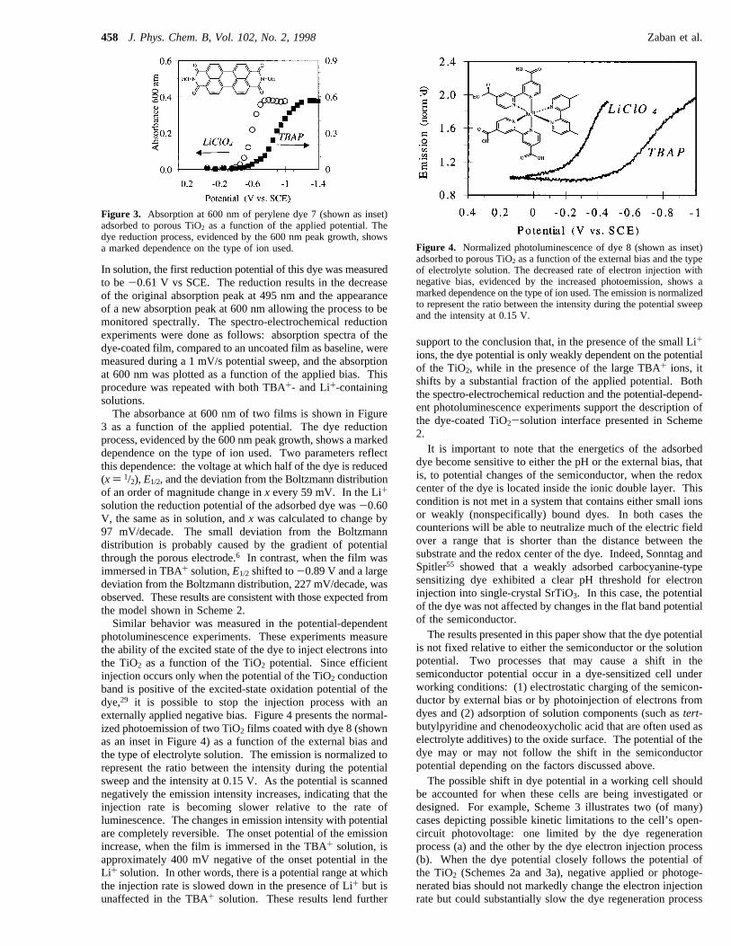
In solution, the first reduction potential of this dye was measuredto be-0.61 V vs SCE. The reduction results in the decreaseof the original absorption peak at 495 nm and the appearanceof a new absorption peak at 600 nm allowing the process to bemonitored spectrally. The spectro-electrochemical reductionexperiments were done as follows: absorption spectra of thedye-coated film, compared to an uncoated film as baseline, weremeasured during a 1 mV/s potential sweep, and the absorptionat 600 nm was plotted as a function of the applied bias. Thisprocedure was repeated with both TBA+- and Li+-containingsolutions.The absorbance at 600 nm of two films is shown in Figure
3 as a function of the applied potential. The dye reductionprocess, evidenced by the 600 nm peak growth, shows a markeddependence on the type of ion used. Two parameters reflectthis dependence: the voltage at which half of the dye is reduced(x) 1/2), E1/2, and the deviation from the Boltzmann distributionof an order of magnitude change inx every 59 mV. In the Li+
solution the reduction potential of the adsorbed dye was-0.60V, the same as in solution, andx was calculated to change by97 mV/decade. The small deviation from the Boltzmanndistribution is probably caused by the gradient of potentialthrough the porous electrode.6 In contrast, when the film wasimmersed in TBA+ solution,E1/2 shifted to-0.89 V and a largedeviation from the Boltzmann distribution, 227 mV/decade, wasobserved. These results are consistent with those expected fromthe model shown in Scheme 2.Similar behavior was measured in the potential-dependent
photoluminescence experiments. These experiments measurethe ability of the excited state of the dye to inject electrons intothe TiO2 as a function of the TiO2 potential. Since efficientinjection occurs only when the potential of the TiO2 conductionband is positive of the excited-state oxidation potential of thedye,29 it is possible to stop the injection process with anexternally applied negative bias. Figure 4 presents the normal-ized photoemission of two TiO2 films coated with dye 8 (shownas an inset in Figure 4) as a function of the external bias andthe type of electrolyte solution. The emission is normalized torepresent the ratio between the intensity during the potentialsweep and the intensity at 0.15 V. As the potential is scannednegatively the emission intensity increases, indicating that theinjection rate is becoming slower relative to the rate ofluminescence. The changes in emission intensity with potentialare completely reversible. The onset potential of the emissionincrease, when the film is immersed in the TBA+ solution, isapproximately 400 mV negative of the onset potential in theLi+ solution. In other words, there is a potential range at whichthe injection rate is slowed down in the presence of Li+ but isunaffected in the TBA+ solution. These results lend further
support to the conclusion that, in the presence of the small Li+
ions, the dye potential is only weakly dependent on the potentialof the TiO2, while in the presence of the large TBA+ ions, itshifts by a substantial fraction of the applied potential. Boththe spectro-electrochemical reduction and the potential-depend-ent photoluminescence experiments support the description ofthe dye-coated TiO2-solution interface presented in Scheme2.It is important to note that the energetics of the adsorbed
dye become sensitive to either the pH or the external bias, thatis, to potential changes of the semiconductor, when the redoxcenter of the dye is located inside the ionic double layer. Thiscondition is not met in a system that contains either small ionsor weakly (nonspecifically) bound dyes. In both cases thecounterions will be able to neutralize much of the electric fieldover a range that is shorter than the distance between thesubstrate and the redox center of the dye. Indeed, Sonntag andSpitler55 showed that a weakly adsorbed carbocyanine-typesensitizing dye exhibited a clear pH threshold for electroninjection into single-crystal SrTiO3. In this case, the potentialof the dye was not affected by changes in the flat band potentialof the semiconductor.The results presented in this paper show that the dye potential
is not fixed relative to either the semiconductor or the solutionpotential. Two processes that may cause a shift in thesemiconductor potential occur in a dye-sensitized cell underworking conditions: (1) electrostatic charging of the semicon-ductor by external bias or by photoinjection of electrons fromdyes and (2) adsorption of solution components (such astert-butylpyridine and chenodeoxycholic acid that are often used aselectrolyte additives) to the oxide surface. The potential of thedye may or may not follow the shift in the semiconductorpotential depending on the factors discussed above.The possible shift in dye potential in a working cell should
be accounted for when these cells are being investigated ordesigned. For example, Scheme 3 illustrates two (of many)cases depicting possible kinetic limitations to the cell’s open-circuit photovoltage: one limited by the dye regenerationprocess (a) and the other by the dye electron injection process(b). When the dye potential closely follows the potential ofthe TiO2 (Schemes 2a and 3a), negative applied or photoge-nerated bias should not markedly change the electron injectionrate but could substantially slow the dye regeneration process
Figure 3. Absorption at 600 nm of perylene dye 7 (shown as inset)adsorbed to porous TiO2 as a function of the applied potential. Thedye reduction process, evidenced by the 600 nm peak growth, showsa marked dependence on the type of ion used. Figure 4. Normalized photoluminescence of dye 8 (shown as inset)
adsorbed to porous TiO2 as a function of the external bias and the typeof electrolyte solution. The decreased rate of electron injection withnegative bias, evidenced by the increased photoemission, shows amarked dependence on the type of ion used. The emission is normalizedto represent the ratio between the intensity during the potential sweepand the intensity at 0.15 V.
458 J. Phys. Chem. B, Vol. 102, No. 2, 1998 Zaban et al.

as the ground-state oxidation potential of the dye becomes morenegative than the solution potential. On the other hand, if thedye potential is almost fixed relative to the solution (Schemes2b and 3b), a negative shift in TiO2 potential should not slowthe regeneration rate but may substantially slow the injectionrate. Other limitations of the open-circuit photovoltage are alsopossible, but whether the dye moves with the TiO2 potential ornot is clearly an important factor to be considered whenattempting to understand or control the open-circuit voltage.Most of the currently reported dye-sensitized solar cells
consist of liquid electrolytes containing small positive andnegative ions (Li+, I-, and I3-). In these systems only smallpotential shifts of the dye relative to solution, but large shiftsrelative to the semiconductor, may be anticipated. In funda-mental investigations, however, large potential shifts may occurrelative to solution when large counterions are used. Largeshifts in the dye potential may also occur in solid-state versionsof the dye-sensitized cell.In an earlier paper6 we reported that electric fields in porous
TiO2 electrodes are neutralized over a short range due to ionmotion through the pores of the TiO2. As a result, a gradientof potential is created both across the porous TiO2 and in theelectrolyte solution that penetrates the pores. In the currentpaper, changes in the relative potentials at the TiO2/dye/electrolyte interface were revealed. When both studies are takeninto account, the following picture emerges: during photovoltaicoperation, the potentials of the TiO2, the solution, and the dyemay all vary with distance from the substrate electrode and mayvary with respect to each other. That is, the local potential ofall three components of the system may vary in a complicatedway throughout the film. This suggests that theoretical modeling
of these systems may be very difficult. In any case, the usualmodels borrowed from standard semiconductor physics are notapplicable to these electrodes.
Conclusion
The effect of specific adsorption to oxide surfaces on theredox potential of sensitizing dyes was studied. The investigateddyes exhibited adsorption-induced pH-dependent redox poten-tials that varied between 21 and 53 mV per pH unit dependingon the dye structure. The redox potential of the dye was alsoaffected by externally applied biases. The magnitude of theseeffects depended on the ability of the electrolyte ions to penetratethe dye layer as well as on the dye structure. When thesensitizing dye is primarily inside the ionic double layer at thesemiconductor oxide/solution interface, its redox potential willtend to follow the changes in the semiconductor potential.When the dye is primarily outside the double layer, its potentialwill be almost independent of the semiconductor potential. Thefact that the potential of the dye is not fixed relative to eitherthe semiconductor or the electrolyte solution has importantimplications for the understanding and optimization of dye-sensitized solar cells.
Acknowledgment. We are grateful to the U.S. Departmentof Energy for funding this research. A.Z. was supported by theOffice of Energy Efficiency and Renewable Energy, Office ofUtility Technologies, Photovoltaics Division; S.F. was supportedby the Office of Energy Research, Office of Computational andTechnology Research, Advanced Energy Projects Division; andB.A.G. was supported by the Office of Energy Research,Division of Basic Energy Sciences, Chemical Sciences Division.
References and Notes
(1) Gerfin, T.; Gratzel, M.; Walder, L. InMolecular LeVel ArtificialPhotosynthetic Materials; Karlin, K. D., Ed.; John Wiley & Sons, Inc.:New York, 1997; pp 345-393.
(2) O’Regan, B.; Gra¨tzel, M. Nature1991, 353, 737-740.(3) Nazeeruddin, M. K.; Kay, A.; Rodicio, I.; Humphry-Baker, R.;
Muller, E. L., P; Vlachopoulos, N.; Gra¨tzel, M. J. Am. Chem. Soc.1993,115, 6382-6390.
(4) Bechinger, C.; Ferrere, S.; Zaban, A.; Sprague, J.; Gregg, B. A.Nature1996, 383, 608-610.
(5) Athanassov, Y.; Rotzinger, F. P.; Pechy, P.; Gra¨tzel, M. J. Phys.Chem. B1997, 101, 2558.
(6) Zaban, A.; Meier, A.; Gregg, B. A.J. Phys. Chem. B, in press.(7) Lindstrom, H.; Rensmo, H.; So¨dergren, S.; Solbrand, A.; Lindquist,
S. E.J. Phys. Chem.1996, 100, 3084.(8) Cao, F.; Oskam, G.; Meyer, G. J.; Searson, P. C.J. Phys. Chem.
1996, 100, 17021.(9) Konenkamp, R.; Wahi, A.; Hoyer, P.Thin Solid Films1994, 246,
13.(10) Boschloo, G. K.; Goossens, A.; Schoonman, J.J. Electroanal.
Chem.1997, 428, 25.(11) Bedja, I.; Kamat, P. V.; Hua, X.; Lappin, A. G.; Hotchandani, S.
Langmuir1997, 13, 2398.(12) Bedja, I.; Hotchandani, S.; Kamat, P. V.J. Phys. Chem.1994, 98,
4133-4140.(13) Ferrere, S.; Zaban, A.; Gregg, B. A.J. Phys. Chem. B1997, 101,
4490-4493.(14) Kay, A.; Gratzel, M. J. Phys. Chem.1993, 97, 6272-6277.(15) Kohle, O.; Ruile, S.; Gra¨tzel, M. Inorg. Chem.1996, 35, 4779.(16) Vogel, R.; Pohl, K.; Weller, H.Chem. Phys. Lett.1990, 174, 241.(17) Hagfeldt, A.; Didriksson, B.; Palmqvist, T.; Lindstrom, H.; So¨der-
gren, S.; Rensmo, H.; Lindquist, S. E.Sol. Energy Mater. Sol. Cells1994,31, 481.
(18) O’Regan, B.; Schwartz, D. T.J. Appl. Phys.1996, 80, 4749.(19) Cao, F.; Oskam, G.; Searson, P. C.J. Phys. Chem.1995, 99, 17071.(20) Tennakone, K.; Kumara, G. R. R. A.; Kumarasinghe, A. R.;
Wijayantha, K. G. U.; Sirimanne, P. M.Semicond. Sci. Technol.1995, 10,1689.
(21) Murakoshi, K.; Kogure, R.; Yanagida, S.Chem. Lett.1997, 5, 471.(22) Hagfeldt, A.; Gra¨tzel, M. Chem. ReV. 1995, 95, 49-68.
SCHEME 3: Simplified Energy Diagram of theSemiconductor/Dye/Electrolyte Interface in a WorkingDye-Sensitized Cella
a The diagrams on the left illustrate the energetics at short circuit,while the diagrams on the right indicate two of the possible kineticlimitations to the open-circuit photovoltage,Voc. (a) When the dyepotential approximately follows the semiconductor potential (conditionsof Scheme 2a),Voc could be limited by the decreasing rate of oxidizeddye regeneration by solution species. (b) When the dye potential isapproximately independent of the semiconductor potential (conditionsof Scheme 2b),Voc could be limited by the decreasing rate ofphotoinjection into the semiconductor. There are many other possiblekinetic limitations toVoc.
Redox Potential of Sensitizing Dyes J. Phys. Chem. B, Vol. 102, No. 2, 1998459

(23) Burfeint, B.; Hannappel, T.; Storck, W.; Willig, F.J. Phys. Chem.1996, 100, 16463-16465.
(24) Rabani, J.; Ushida, K.; Koichi, Y.; Stark, J.; Gershuni, S.; Kira, A.J. Phys. Chem. B1997, 101, 3136.
(25) Argazzi, R.; Bignozzi, C. A.; Heimer, T. A.; Meyer, G. J.Inorg.Chem.1997, 36, 2-3.
(26) Murakoshi, K.; Kano, G.; Wada, Y.; Yanagida, S.; Miyazaki, H.;Matsumoto, M.; Murasawa, S.J. Electroanal. Chem.1995, 396, 27-34.
(27) Heimer, T. A.; D’Arcangelis, S. T.; Farzad, F.; Stipkala, J. M.;Meyer, G. J.Inorg. Chem.1996, 35, 5319.
(28) Huang, S. Y.; Schlichtho¨rl, G.; Nozik, A. J.; Gra¨tzel, M.; Frank,A. J. J. Phys. Chem. B1997, 101, 2576-2582.
(29) Parkinson, B. A.; Spitler, M. T.Electrochim. Acta.1992, 37, 943.(30) Sodergren, S.; Hagfeldt, A.; Olsson, J.; Lindquist, S. E.J. Phys.
Chem.1994, 98, 5552.(31) Fitzmaurice, D.Sol. Energy Mater. Sol. Cells1994, 32, 289.(32) Lyon, L. A.; Hupp, J. T.J. Phys. Chem.1995, 99, 15718.(33) Elliott, C. M.; Hershenhart, E. J.J. Am. Chem. Soc.1982, 104,
7519.(34) Cao, F.; Oskam, G.; Searson, P. C.; Stipkala, J. M.; Heimer, T. A.;
Farzad, F.; Meyer, G. J.J. Phys. Chem.1995, 99, 11974.(35) Zaban, A.; Ferrere, S.; Sprague, J.; Gregg, B. A.J. Phys. Chem.
1997, 101, 55-57.(36) Nozik, A. J.Annu. ReV. Phys. Chem.1978, 29, 189-222.(37) Gerischer, H.Electrochim. Acta1989, 34, 1005.(38) Elliott, C. M.; Freitag, R. A.; Blaney, D. D.J. Am. Chem. Soc.
1985, 107, 4647-4655.
(39) Gould, S.; Strouse, G.; Meyer, T. J.; Sullivan, B. P.Inorg. Chem.1991, 30, 2942-2949.
(40) Jones, R. A.; Roney, B. D.; Sasse, W. H. F.; Wade, K. O.J. ChemSoc. B1967, 106-111.
(41) Yan, S. G.; Hupp, J. T.J. Phys. Chem.1996, 100, 6867-6870.(42) Hirao, T.; Masunaga, T.; Ohshiro, Y.; Agawa, T.Synthesis1981,
1, 56-57.(43) Sasse, W. H. F.; Whittle, C. P.J. Am. Chem. Soc.1961, 83, 1347.(44) Pechy, P.; Rotzinger, F. P.; Nazeeruddin, M. K.; Kohle, O.;
Zakeeruddin, S. M.; Humphry-Baker, R.; Gra¨tzel, M.J. Chem. Soc., Chem.Commun.1995, 65-66.
(45) Constable, E. C.; Ward, M. D.J. Chem. Soc., Dalton Trans.1990,1405.
(46) Sullivan, B. P.; Calvert, J. M.; Meyer, T. J.Inorg. Chem1980, 19,1404-1407.
(47) Sullivan, B. P.; Salmon, D. J.; Meyer, T. J.Inorg. Chem1978, 17,3334-3341.
(48) Shirai, H.; Yagi, S.; Suzuki, A.; Hojo, N.Makromol. Chem.1977,178, 1889-1895.
(49) Ford, W. E.J. Photochem.1987, 37, 189-204.(50) Bard, A. J.; Faulkner, L. R.Electrochemical Methods Fundamental
and Applications; John Wiley & Sons: New York, 1980.(51) Chidsey, C. E. D.Science1991, 251, 919.(52) Finklea, H. O.; Hanshew, D. D.J. Am. Chem. Soc.1992, 114, 3173.(53) Smith, C. P.; White, H. S.Anal. Chem.1992, 64, 2398-2405.(54) Creager, S. E.; Weber, K.Langmuir1993, 9, 844-850.(55) Sonntag, L. R.; Spitler, M. T.J. Phys. Chem.1985, 89, 1453.
460 J. Phys. Chem. B, Vol. 102, No. 2, 1998 Zaban et al.