
Principles of fluid and electrolyte balance in surgical patients
A
aXdfPabro©
K
1
aobtlit
o
0d
Available online at www.sciencedirect.com
Journal of Power Sources 179 (2008) 532–540
Pt-based electrocatalysts for polymer electrolyte membrane fuelcells prepared by supercritical deposition technique
Ayse Bayrakceken a, Alevtina Smirnova b, Usanee Kitkamthorn b,1,Mark Aindow b, Lemi Turker c, Inci Eroglu a, Can Erkey d,∗a Department of Chemical Engineering, Middle East Technical University, Ankara 06531, Turkey
b Department of Chemical, Materials and Biomolecular Engineering, and Institute of Materials Science,University of Connecticut, Storrs, CT 06269-3136, USA
c Department of Chemistry, Middle East Technical University, Ankara 06531, Turkeyd Department of Chemical and Biological Engineering, Koc University, 34450 Sariyer, Istanbul, Turkey
Received 24 August 2007; received in revised form 11 December 2007; accepted 24 December 2007Available online 4 January 2008
bstract
Pt-based electrocatalysts were prepared on different carbon supports which are multiwall carbon nanotubes (MWCNTs), Vulcan XC 72R (VXR)nd black pearl 2000 (BP2000) using a supercritical carbon dioxide (scCO2) deposition technique. These catalysts were characterized by using-ray diffraction (XRD), high-resolution transmission electron microscopy (HRTEM) and cyclic voltammetry (CV). XRD and HRTEM resultsemonstrated that the scCO2 deposition technique enables a high surface area metal phase to be deposited, with the size of the Pt particles rangingrom 1 to 2 nm. The electrochemical surface areas (ESAs) of the prepared electrocatalysts were compared to the surface areas of commercial ETEKt/C (10 wt% Pt) and Tanaka Pt/C (46.5 wt% Pt) catalysts. The CV data indicate that the ESAs of the prepared Pt/VXR and Pt/MWCNT catalystsre about three times larger than that of the commercial ETEK catalyst for similar (10 wt% Pt) loadings. Oxygen reduction activity was investigated
y hydrodynamic voltammetry. From the slope of Koutecky–Levich plots, the average number of electrons transferred in the oxygen reductioneaction (ORR) was 3.5, 3.6 and 3.7 for Pt/BP2000, Pt/VXR and Pt/MWCNT, correspondingly, which indicated almost complete reduction ofxygen to water.2008 Published by Elsevier B.V.
lyme
tohaioo
eywords: Supercritical carbon dioxide deposition; Electrocatalyst; Carbon; Po
. Introduction
A polymer electrolyte membrane fuel cell (PEMFC) containsmembrane electrode assembly (MEA) typically consisting
f an ionically conducting polymeric membrane sandwichedetween two electronically conducting electrodes. Typical elec-rodes for PEMFC applications are made of a gas diffusion
ayer (usually porous carbon paper or carbon cloth) support-ng a layer of finely dispersed Pt on carbon catalyst. Platinum ishe most extensively used metal in the anode and cathode elec-∗ Corresponding author. Tel.: +90 2123381866; fax: +90 2123381548.E-mail address: [email protected] (C. Erkey).
1 Present address: School of Metallurgical Engineering, Suranaree Universityf Technology, Muang, Nakorn Ratchasima 30000, Thailand.
lot
diac[
378-7753/$ – see front matter © 2008 Published by Elsevier B.V.oi:10.1016/j.jpowsour.2007.12.086
r electrolyte membrane fuel cell; Platinum
rodes of PEMFCs because of its high catalytic activity for bothxidation and reduction reactions [1]. The high cost of Pt is pro-ibitive for commercialization of PEMFCs and research effortsre directed to reduce the amount of platinum utilized by improv-ng membrane electrode assembly preparation techniques [2–5]r structures of carbon-supported catalysts [6,7]. The activitiesf the catalysts depend on several parameters such as the cata-yst preparation technique, the type of carbon support, propertiesf the precursor, accessibility of the metal on the support, andesting conditions.
In the past, several different methods were utilized toeposit platinum on different carbon supports; these include:
mpregnation-reduction [8] microemulsion-based synthesis [9]nd ion exchange [10]. The carbon supports used included Vul-an XC 72 R (VXR) [11], multiwall carbon nanotube (MWCNT)12,13], carbon aerogel [14], activated carbon [15], black pearl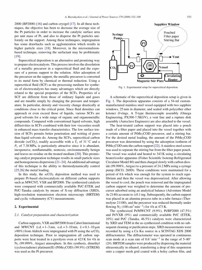
f Power Sources 179 (2008) 532–540 533
2ntpfhhb[
tosttssrSaacagcdistdPiaiao[
pswPha
2
2
a>dpN(w
FmwkEa
maFpPwThCippltccAwmfl
a1bsrd
A. Bayrakceken et al. / Journal o
000 (BP2000) [16] and carbon cryogel [17]. In all these tech-iques, the objective has been to decrease the average size ofhe Pt particles in order to increase the catalytic surface areaer unit mass of Pt, and also to disperse the Pt particles uni-ormly on the support. Among these techniques, impregnationas some drawbacks such as agglomeration which results inigher particle sizes [18]. Moreover, in the microemulsion-ased technique, removing the surfactant may be problematic19].
Supercritical deposition is an alternative and promising wayo prepare electrocatalysts. This process involves the dissolutionf a metallic precursor in a supercritical fluid and the expo-ure of a porous support to the solution. After adsorption ofhe precursor on the support, the metallic precursor is convertedo its metal form by chemical or thermal reduction. Using aupercritical fluid (SCF) as the processing medium for synthe-is of electrocatalysts has many advantages which are directlyelated to the special properties of the SCFs. Properties of aCF are different from those of ordinary liquids and gasesnd are tunable simply by changing the pressure and temper-ture. In particular, density and viscosity change drastically atonditions close to the critical point. Since fluid densities canpproach or even exceed those of liquids, various SCFs areood solvents for a wide range of organic and organometallicompounds. Compared with conventional liquid solvents, highiffusivities in SCFs combined with their low viscosities resultn enhanced mass transfer characteristics. The low surface ten-ion of SCFs permits better penetration and wetting of poreshan liquid solvents do. Among the SCFs, supercritical carbonioxide (scCO2), readily accessible with a Tc of 31 ◦C and ac of 7.38 MPa, is particularly attractive since it is abundant,
nexpensive, nonflammable, nontoxic, environmentally benignnd leaves no residue on the treated medium [20]. This promis-ng catalyst preparation technique results in small particle sizesnd homogeneous dispersions [21–24]. An additional advantagef this technique is the ability to thermodynamically control25,26] the metal loading.
In this study, the scCO2 deposition method was used torepare Pt-based electrocatalysts on different carbon supportsuch as MWCNT, VXR and BP2000. The synthesized catalystsere compared with commercially available Pt/C-ETEK andt/C-Tanaka catalysts by means of X-ray diffraction (XRD),igh-resolution transmission electron microscopy (HRTEM)nd cyclic voltammetry (CV) measurements.
. Experimental
.1. Catalyst preparation and characterization
Carbon supports, VXR and BP2000 from Cabot Internationalnd MWCNT (i.d. = 1–3 nm, o.d. = 3–10 nm, L = 0.1–10 �m90%) from Aldrich were impregnated with Pt using the scCO2eposition technique. Prior to impregnation all carbon sup-
orts were heat treated in a pyrolysis oven at 423 K for 4 h in2 (99.999%, Airgas) atmosphere. In this synthesis, dimethylcyclooctadiene) platinum(II) (PtMe2COD) (99.9%) (STREM)as used as the Pt precursor.
s(uo
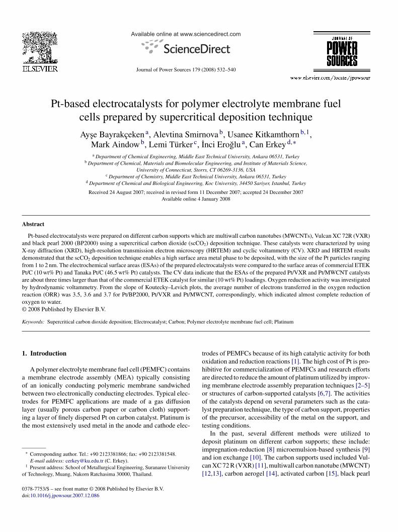
Fig. 1. Experimental setup for supercritical deposition.
A schematic of the supercritical deposition setup is given inig. 1. The deposition apparatus consists of a 54-ml custom-anufactured stainless steel vessel equipped with two sapphireindows, 25 mm in diameter, and sealed with poly(ether etheretone) O-rings. A T-type thermocouple assembly (Omegangineering, PX300-7.5KGV), a vent line and a rupture diskssembly (Autoclave Engineers) are also attached to the vessel.
The heat-treated carbon support was placed into a pouchade of a filter paper and placed into the vessel together withcertain amount of PtMe2COD precursor, and a stirring bar.
or the desired metal loading, the amount of the PtMe2CODrecursor was determined by using the adsorption isotherm oftMe2COD onto the carbon support [22]. A stainless steel screenas used to separate the stirring bar from the filter paper pouch.he vessel was sealed and heated to 343 K using a circulatingeater/cooler apparatus (Fisher Scientific Isotemp Refrigeratedirculator Model 80) and then charged slowly with carbon diox-
de (99.998%, Airgas) to a pressure of 24.2 MPa using a syringeump (ISCO, 260D). These conditions were maintained for aeriod of 6 h which was enough for the system to reach equi-ibrium and then the vessel was depressurized. After allowinghe vessel to cool, the pouch was removed and the impregnatedarbon support was weighed to determine the amount of pre-ursor adsorbed using an analytical balance (Adventure Modelr 2140) accurate to ±0.1 mg. Subsequently, the carbon supportas placed in an alumina process tube in a tube furnace (Ther-olyne 21100), and the precursor was reduced thermally underowing N2 (100 cm3 min−1) for 4 h at 473 K.
The synthesized Pt/MWCNT (9.9%), Pt/BP2000 (47.5%)nd Pt/VXR (9%) and commercially available Pt/C (ETEK,0%) and Pt/C (Tanaka, 46.5%) catalysts were characterizedy XRD and TEM in the as-synthesized condition with no sub-equent cleaning or purification steps. XRD measurements wereecorded by using a Cu K� source in a SCINTAG XDS 2000iffractometer. The diffractometer was operated in continuous
can mode at a scan rate of 0.6◦ min−1 in the range of 5–80◦2θ). HRTEM samples were produced by dispersing the materialltrasonically in ethanol, transferring a drop of this suspensionnto a copper mesh grid coated with a holey carbon film, and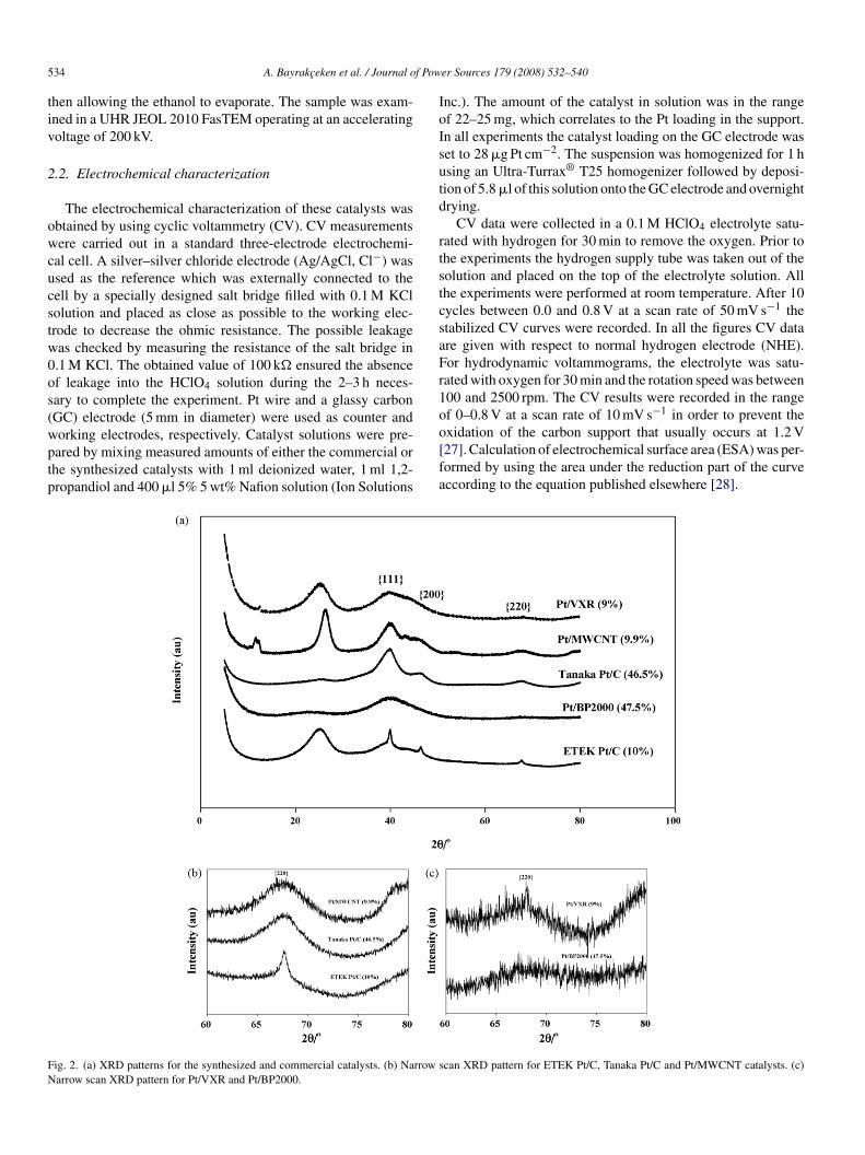
5 f Pow
tiv
2
owcucstw0os(wptp
IoIsutd
rtstcsaFr1o
FN
34 A. Bayrakceken et al. / Journal o
hen allowing the ethanol to evaporate. The sample was exam-ned in a UHR JEOL 2010 FasTEM operating at an acceleratingoltage of 200 kV.
.2. Electrochemical characterization
The electrochemical characterization of these catalysts wasbtained by using cyclic voltammetry (CV). CV measurementsere carried out in a standard three-electrode electrochemi-
al cell. A silver–silver chloride electrode (Ag/AgCl, Cl−) wassed as the reference which was externally connected to theell by a specially designed salt bridge filled with 0.1 M KClolution and placed as close as possible to the working elec-rode to decrease the ohmic resistance. The possible leakageas checked by measuring the resistance of the salt bridge in.1 M KCl. The obtained value of 100 k� ensured the absencef leakage into the HClO4 solution during the 2–3 h neces-ary to complete the experiment. Pt wire and a glassy carbonGC) electrode (5 mm in diameter) were used as counter and
orking electrodes, respectively. Catalyst solutions were pre-ared by mixing measured amounts of either the commercial orhe synthesized catalysts with 1 ml deionized water, 1 ml 1,2-ropandiol and 400 �l 5% 5 wt% Nafion solution (Ion Solutionso[fa
ig. 2. (a) XRD patterns for the synthesized and commercial catalysts. (b) Narrow sarrow scan XRD pattern for Pt/VXR and Pt/BP2000.
er Sources 179 (2008) 532–540
nc.). The amount of the catalyst in solution was in the rangef 22–25 mg, which correlates to the Pt loading in the support.n all experiments the catalyst loading on the GC electrode waset to 28 �g Pt cm−2. The suspension was homogenized for 1 hsing an Ultra-Turrax® T25 homogenizer followed by deposi-ion of 5.8 �l of this solution onto the GC electrode and overnightrying.
CV data were collected in a 0.1 M HClO4 electrolyte satu-ated with hydrogen for 30 min to remove the oxygen. Prior tohe experiments the hydrogen supply tube was taken out of theolution and placed on the top of the electrolyte solution. Allhe experiments were performed at room temperature. After 10ycles between 0.0 and 0.8 V at a scan rate of 50 mV s−1 thetabilized CV curves were recorded. In all the figures CV datare given with respect to normal hydrogen electrode (NHE).or hydrodynamic voltammograms, the electrolyte was satu-ated with oxygen for 30 min and the rotation speed was between00 and 2500 rpm. The CV results were recorded in the rangef 0–0.8 V at a scan rate of 10 mV s−1 in order to prevent the
xidation of the carbon support that usually occurs at 1.2 V27]. Calculation of electrochemical surface area (ESA) was per-ormed by using the area under the reduction part of the curveccording to the equation published elsewhere [28].can XRD pattern for ETEK Pt/C, Tanaka Pt/C and Pt/MWCNT catalysts. (c)
f Pow
3
a[
a{PowwrfPTdXapm
cPatatotcastfit
fwotvtc
4
olaehtV
ptl(ibPt
aStfahtintaPprWh[
isptctli
TE
C
PPPPP
A. Bayrakceken et al. / Journal o
. Results and discussion
The carbon supports used in this study were VXR, BP2000nd MWCNT which have total surface areas of 235 [8], 145029] and 300 (Aldrich) m2 g−1, respectively.
The XRD spectra for the prepared and commercial catalystsre presented in Fig. 2(a). For all catalysts the characteristic1 1 1}, {2 0 0}, {2 2 0} peaks for face-centered cubic (fcc)t were obtained. Because the {1 1 1}, and {2 0 0} Pt peaksverlapped the broad C peaks, the sizes of the Pt particlesere calculated from the Scherrer equation using the half fullidth at half maximum of the {2 2 0} reflection [30]. High-
esolution XRD spectra obtained over the range 2θ = 60–80◦rom the catalysts ETEK Pt/C, Tanaka Pt/C, Pt/MWCNT andt/BP2000, Pt/VXR are given in Fig. 2(b) and (c), respectively.he equivalent surface area (SA) of the metal phase (Pt) wasetermined using the mean particle sizes obtained from theRD data [31]. The mean particle sizes are given in Table 1
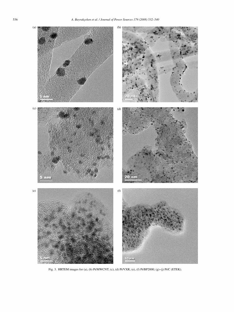
nd indicate that highly dispersed Pt catalysts with small Ptarticle sizes were obtained by using the scCO2 depositionethod.HRTEM images obtained from the synthesized and commer-
ial catalysts are presented in Fig. 3 for Pt/MWCNT (a), (b);t/VXR (c), (d); Pt/BP2000 (e), (f) and ETEK Pt/C (g)–(j). Ingreement with XRD data, it can be seen that a small Pt par-icle size of about 1–2 nm and uniform Pt distribution can bechieved using the scCO2 deposition method. From the litera-ure [32] and the ETEK company data the size of the Pt particlesf ETEK Pt/C (10 wt%) catalyst was around 2–3 nm. However,he calculations based on the XRD data gave a particle size oflose to 6 nm. The reason for this discrepancy is that there isbroad Pt particle size distribution in the ETEK catalyst as
hown by the TEM data presented in Fig. 3(g)–(j). On the con-rary, there is a good agreement between XRD and TEM dataor the samples synthesized by the scCO2 deposition technique,ndicating that they have a very narrow particle size distribu-ion.
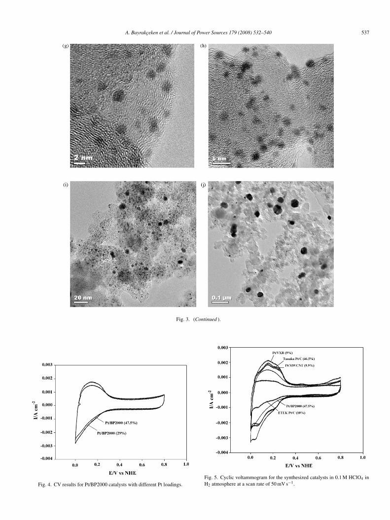
Among the carbon supports, the BP2000 has the highest sur-ace area and it is this support on which the highest Pt loadingas achieved in this work (47.5%). This is due to highest uptakef the Pt precursor due to the highest surface area. However, forhe Pt/BP2000 catalysts that have different Pt loadings, the ESAalues obtained were approximately the same, presumably due
o similar size of the Pt particles (≈1 nm in diameter) which wasonfirmed by the XRD measurements.CV results for the Pt/BP2000 catalysts which have 29 and7.5 wt% Pt loadings are given in Fig. 4. The catalytic activity
peab
able 1lectrochemical and total surface area of the prepared and commercial catalysts
atalyst d (nm)a SAPt (m2 g−1) ESA
t/C (ETEK) 6 46.73 57t/VXR (scCO2) 1.2 233.64 173t/MWCNT (scCO2) 2 140.2 130t/BP2000 (scCO2) 1 280.4 102t/C (Tanaka) 2 140.2 128
a From XRD data.
er Sources 179 (2008) 532–540 535
f these catalysts are very similar despite substantially differentoadings. As demonstrated by the CV data in Fig. 5, the catalyticctivity of the Pt/VXR prepared by supercritical deposition forlectro-oxidation and reduction of hydrogen is substantiallyigher than the catalytic activity of commercial Pt/VXR. Amonghe three different supports utilized in supercritical deposition,XR has the highest catalytic activity.The calculated surface area and electrochemical surface area
arameters are given in Table 1. Although Pt/VXR (scCO2) hashe highest ESA and a low particle diameter (Table 1), the Pt uti-ization is only 74%. It can be assumed that in the case of small∼1 nm) Pt particles, the accessibility of the metal particles evenn liquid electrolyte is more critical due to the partially hydropho-ic nature of the carbon support. For Pt/MWCNT (scCO2) andt/C (Tanaka), which have larger Pt particles (2 nm), the utiliza-
ion of Pt seems to be higher.The ESA values for the Pt/BP2000 catalysts which have 29
nd 47.5 wt% Pt loadings are 110 and 102 m2 g−1, respectively.imilar ESA values at substantially different loadings indicate
hat ESAs are primarily governed by the platinum particle sizeor the same support. Even though the particle size of Pt on VXRnd BP2000 is approximately the same, the ESA of Pt/VXR isigher which results in a large difference in the Pt utilization forhese two materials (Table 1). This could be due to differencesn the structures of the carbon supports for these two catalysts,amely by the higher micropore volume of BP2000. Some ofhe platinum nanoparticles may be residing in the microporesnd the electrolyte may not be contacting these particles. Thet utilization value of over 100% in the case of Pt/C (ETEK)resumably arises because the Pt particle size is not uniform, asevealed in the HRTEM images from this material (Fig. 3(g)–(j)).
e note, however, that Pt utilization values of over 100%ave been reported elsewhere for ETEK Pt/C (20%) catalyst33].
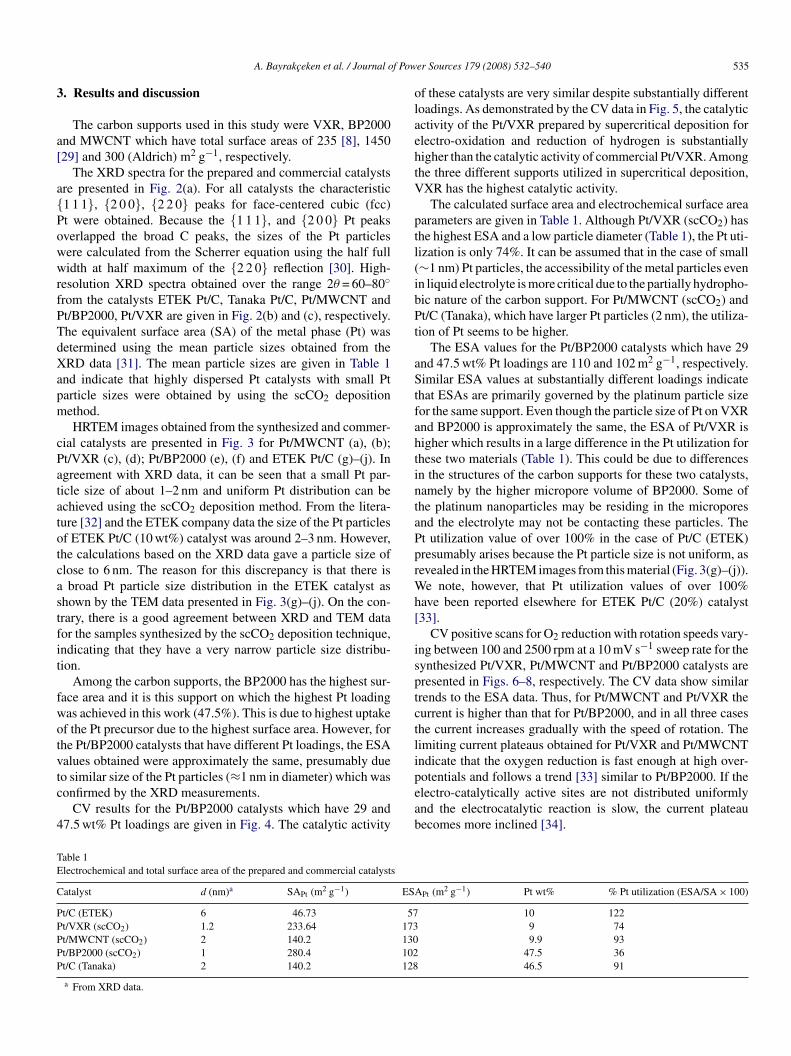
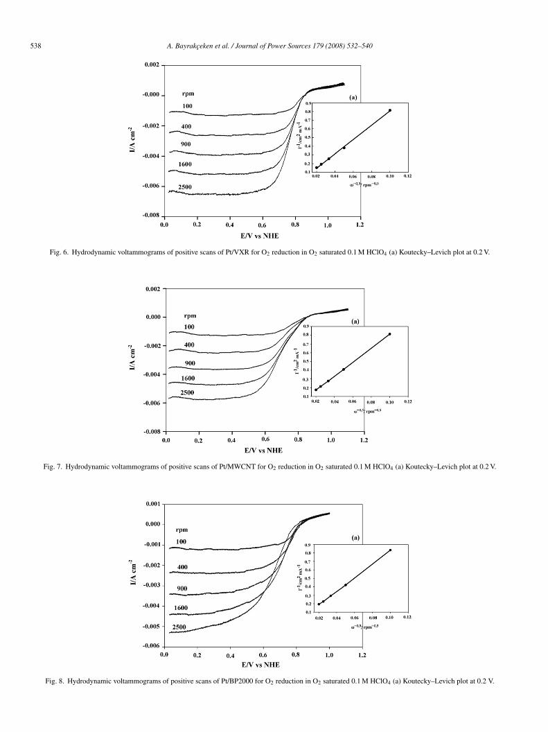
CV positive scans for O2 reduction with rotation speeds vary-ng between 100 and 2500 rpm at a 10 mV s−1 sweep rate for theynthesized Pt/VXR, Pt/MWCNT and Pt/BP2000 catalysts areresented in Figs. 6–8, respectively. The CV data show similarrends to the ESA data. Thus, for Pt/MWCNT and Pt/VXR theurrent is higher than that for Pt/BP2000, and in all three caseshe current increases gradually with the speed of rotation. Theimiting current plateaus obtained for Pt/VXR and Pt/MWCNTndicate that the oxygen reduction is fast enough at high over-
otentials and follows a trend [33] similar to Pt/BP2000. If thelectro-catalytically active sites are not distributed uniformlynd the electrocatalytic reaction is slow, the current plateauecomes more inclined [34].Pt (m2 g−1) Pt wt% % Pt utilization (ESA/SA × 100)
10 1229 749.9 93
47.5 3646.5 91
536 A. Bayrakceken et al. / Journal of Power Sources 179 (2008) 532–540
Fig. 3. HRTEM images for (a), (b) Pt/MWCNT; (c), (d) Pt/VXR; (e), (f) Pt/BP2000; (g)–(j) Pt/C (ETEK).
A. Bayrakceken et al. / Journal of Power Sources 179 (2008) 532–540 537
Fig. 3. (Continued ).
Fig. 4. CV results for Pt/BP2000 catalysts with different Pt loadings.Fig. 5. Cyclic voltammogram for the synthesized catalysts in 0.1 M HClO4 inH2 atmosphere at a scan rate of 50 mV s−1.
538 A. Bayrakceken et al. / Journal of Pow
Fig. 6. Hydrodynamic voltammograms of positive scans of Pt/VXR for O2 red
Fig. 7. Hydrodynamic voltammograms of positive scans of Pt/MWCNT for O2 r
Fig. 8. Hydrodynamic voltammograms of positive scans of Pt/BP2000 for O2 re
er Sources 179 (2008) 532–540
uction in O2 saturated 0.1 M HClO4 (a) Koutecky–Levich plot at 0.2 V.
eduction in O2 saturated 0.1 M HClO4 (a) Koutecky–Levich plot at 0.2 V.
duction in O2 saturated 0.1 M HClO4 (a) Koutecky–Levich plot at 0.2 V.
A. Bayrakceken et al. / Journal of Pow
Fc
p
Tiplgcppm
B
wtcdctt(
wefTca
raia1t
r1amoraTiOrbwOr
4
ustdiredascPaa
gPtwaofa
A
aU
R
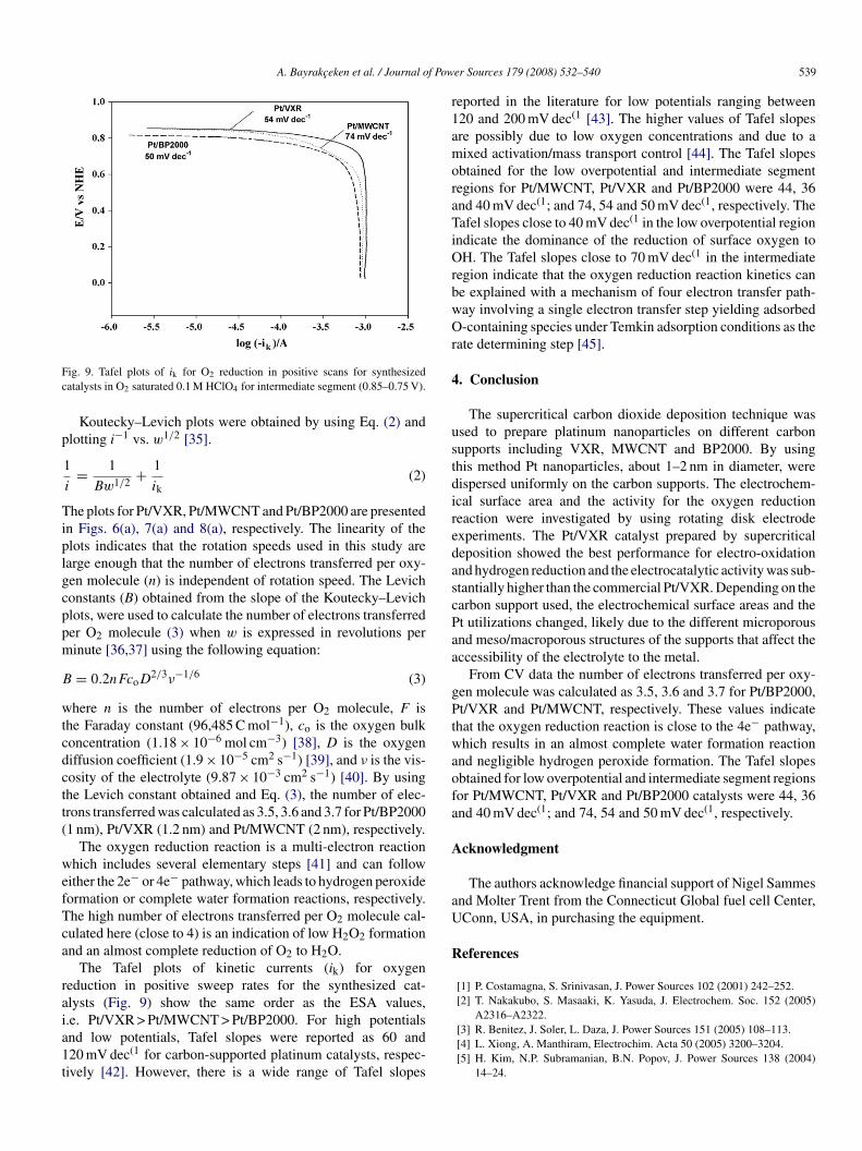
ig. 9. Tafel plots of ik for O2 reduction in positive scans for synthesizedatalysts in O2 saturated 0.1 M HClO4 for intermediate segment (0.85–0.75 V).
Koutecky–Levich plots were obtained by using Eq. (2) andlotting i−1 vs. w1/2 [35].
1
i= 1
Bw1/2 + 1
ik(2)
he plots for Pt/VXR, Pt/MWCNT and Pt/BP2000 are presentedn Figs. 6(a), 7(a) and 8(a), respectively. The linearity of thelots indicates that the rotation speeds used in this study arearge enough that the number of electrons transferred per oxy-en molecule (n) is independent of rotation speed. The Levichonstants (B) obtained from the slope of the Koutecky–Levichlots, were used to calculate the number of electrons transferreder O2 molecule (3) when w is expressed in revolutions perinute [36,37] using the following equation:
= 0.2nFcoD2/3ν−1/6 (3)
here n is the number of electrons per O2 molecule, F ishe Faraday constant (96,485 C mol−1), co is the oxygen bulkoncentration (1.18 × 10⁻⁶ mol cm−3) [38], D is the oxygeniffusion coefficient (1.9 × 10⁻⁵ cm2 s−1) [39], and ν is the vis-osity of the electrolyte (9.87 × 10⁻³ cm2 s−1) [40]. By usinghe Levich constant obtained and Eq. (3), the number of elec-rons transferred was calculated as 3.5, 3.6 and 3.7 for Pt/BP20001 nm), Pt/VXR (1.2 nm) and Pt/MWCNT (2 nm), respectively.
The oxygen reduction reaction is a multi-electron reactionhich includes several elementary steps [41] and can follow
ither the 2e− or 4e− pathway, which leads to hydrogen peroxideormation or complete water formation reactions, respectively.he high number of electrons transferred per O2 molecule cal-ulated here (close to 4) is an indication of low H2O2 formationnd an almost complete reduction of O2 to H2O.
The Tafel plots of kinetic currents (ik) for oxygeneduction in positive sweep rates for the synthesized cat-lysts (Fig. 9) show the same order as the ESA values,
.e. Pt/VXR > Pt/MWCNT > Pt/BP2000. For high potentialsnd low potentials, Tafel slopes were reported as 60 and20 mV dec(1 for carbon-supported platinum catalysts, respec-ively [42]. However, there is a wide range of Tafel slopeser Sources 179 (2008) 532–540 539
eported in the literature for low potentials ranging between20 and 200 mV dec(1 [43]. The higher values of Tafel slopesre possibly due to low oxygen concentrations and due to aixed activation/mass transport control [44]. The Tafel slopes
btained for the low overpotential and intermediate segmentegions for Pt/MWCNT, Pt/VXR and Pt/BP2000 were 44, 36nd 40 mV dec(1; and 74, 54 and 50 mV dec(1, respectively. Theafel slopes close to 40 mV dec(1 in the low overpotential region
ndicate the dominance of the reduction of surface oxygen toH. The Tafel slopes close to 70 mV dec(1 in the intermediate
egion indicate that the oxygen reduction reaction kinetics cane explained with a mechanism of four electron transfer path-ay involving a single electron transfer step yielding adsorbed-containing species under Temkin adsorption conditions as the
ate determining step [45].
. Conclusion
The supercritical carbon dioxide deposition technique wassed to prepare platinum nanoparticles on different carbonupports including VXR, MWCNT and BP2000. By usinghis method Pt nanoparticles, about 1–2 nm in diameter, wereispersed uniformly on the carbon supports. The electrochem-cal surface area and the activity for the oxygen reductioneaction were investigated by using rotating disk electrodexperiments. The Pt/VXR catalyst prepared by supercriticaleposition showed the best performance for electro-oxidationnd hydrogen reduction and the electrocatalytic activity was sub-tantially higher than the commercial Pt/VXR. Depending on thearbon support used, the electrochemical surface areas and thet utilizations changed, likely due to the different microporousnd meso/macroporous structures of the supports that affect theccessibility of the electrolyte to the metal.
From CV data the number of electrons transferred per oxy-en molecule was calculated as 3.5, 3.6 and 3.7 for Pt/BP2000,t/VXR and Pt/MWCNT, respectively. These values indicate
hat the oxygen reduction reaction is close to the 4e− pathway,hich results in an almost complete water formation reaction
nd negligible hydrogen peroxide formation. The Tafel slopesbtained for low overpotential and intermediate segment regionsor Pt/MWCNT, Pt/VXR and Pt/BP2000 catalysts were 44, 36nd 40 mV dec(1; and 74, 54 and 50 mV dec(1, respectively.
cknowledgment
The authors acknowledge financial support of Nigel Sammesnd Molter Trent from the Connecticut Global fuel cell Center,Conn, USA, in purchasing the equipment.
eferences
[1] P. Costamagna, S. Srinivasan, J. Power Sources 102 (2001) 242–252.[2] T. Nakakubo, S. Masaaki, K. Yasuda, J. Electrochem. Soc. 152 (2005)
A2316–A2322.[3] R. Benitez, J. Soler, L. Daza, J. Power Sources 151 (2005) 108–113.[4] L. Xiong, A. Manthiram, Electrochim. Acta 50 (2005) 3200–3204.[5] H. Kim, N.P. Subramanian, B.N. Popov, J. Power Sources 138 (2004)
14–24.
5 f Pow
[
[
[
[
[
[[
[
[[
[[
[
[
[
[
[
[
[
[
[
[
[
[[
[
[
[
[
[
[
[
[
40 A. Bayrakceken et al. / Journal o
[6] T. Kawaguchi, W. Sugimoto, Y. Murakami, Y. Takasu, J. Catal. 229 (2005)176–184.
[7] Z. Zhou, W. Zhou, S. Wang, G. Wang, L. Jiang, H. Li, G. Sun, Q. Xin,Catal. Today 93 (2004) 523–528.
[8] J. Zhang, X. Wang, C. Wu, H. Wang, B. Yi, H. Zhang, React. Kinet. Catal.Lett. 83 (2004) 229–236.
[9] M.J. Escudero, E. Hontanon, S. Schwartz, B. Boutonnet, L. Daza, J. PowerSources 106 (2002) 206–214.
10] Y. Shao, G. Yin, J. Wang, Y. Gao, P. Shi, J. Power Sources 161 (2006)47–53.
11] V. Raghuveer, A. Manthiram, Electrochem. Solid-State Lett. 7 (2004)A336–A339.
12] Z. Liu, X. Lin, J.Y. Lee, W. Zhang, M. Han, L.M. Gan, Langmuir 18. (2002)4054–4060.
13] W. Li, C. Liang, W. Zhou, J. Qiu, Z. Zhou, G. Sun, Q. Xin, J. Phys. Chem.B 107 (2003) 6292–6299.
14] J. Marie, S. Berthon-Fabry, P. Achard, M. Chatenet, A. Pradourat, E.Chainet, J. Non-Crystal. Solids 350 (2004) 88–96.
15] J. Maruyama, I. Abe, Electrochim. Acta 48 (2003) 1443–1450.16] K. Amine, K. Yasuda, H. Takenaka, Ann. Chim. Sci. Mat. 23 (1998)
331–335.17] B.M. Babic, Lj.M. Vracar, V. Radmilovic, N.V. Krstajic, Electrochim. Acta
51 (2005) 3820–3826.18] C.L. Hui, X.G. Li, I.M. Hsing, Electrochim. Acta 51 (2005) 711–719.19] K.M.K. Yu, C.M.Y. Yeung, D. Thompsett, S.C. Tsang, J. Phys. Chem. B
107 (2003) 4515–4526.20] Y. Zhang, C. Erkey, J. Supercrit. Fluids 38 (2006) 252–267.21] A. Bayrakceken, U. Kitkamthorn, M. Aindow, C. Erkey, Scr. Mater. 56
(2007) 101–103.22] Y. Zhang, D. Kang, C. Saquing, M. Aindow, C. Erkey, Ind. Eng. Chem.
Res. 44 (2005) 4161–4164.23] A. Smirnova, X. Dong, H. Hara, N. Sammes, J. Fuel Cell Sci. Technol. 3
(2006) 477–481.24] Y. Zhang, D. Kang, M. Aindow, C. Erkey, J. Phys. Chem. B 109 (2005)
2617–2624.25] C.D. Saquing, T.T. Cheng, M. Aindow, C. Erkey, J. Phys. Chem. B 108
(2004) 7716–7722.
[[
[
er Sources 179 (2008) 532–540
26] C.D. Saquing, D. Kang, M. Aindow, C. Erkey, Micropor. Mesopor. Mater.80 (2005) 11–23.
27] H.A. Gasteiger, J.E. Panels, S.G. Yan, J. Power Sources 127 (2004)162–171.
28] A. Smirnova, X. Dong, H. Hara, A. Vasiliev, N. Sammes, Int. J. HydrogenEnergy 30 (2005) 149–158.
29] M. Kruk, M. Jaroniec, Y. Bereznitzki, J. Colloid Interface Sci. 182 (1996)282–286.
30] Z.W. Zhao, Z.P. Guo, J. Ding, D. Wexler, Z.F. Ma, D.Y. Zhang, H.K. Liu,Electrochem. Commun. 8 (2006) 245–250.
31] A. Pozio, M.D.E. Francesco, A. Cemmi, F. Cardellini, L. Giorgi, J. PowerSources 105 (2002) 13–19.
32] F. Gloaguen, J.M. Leger, C. Lamy, J. Appl. Electrochem. 27 (1997)1052–1060.
33] J. Shan, P.G. Pickup, Electrochem. Acta 46 (2000) 119–125.34] K. Suarez-Alcantara, A. Rodrıguez-Castellanos, R. Dante, O. Solorza-
Feria, J. Power Sources 157 (2006) 114–120.35] M. Bron, S. Fiechter, M. Hilgendorff, P. Bogdanoff, J. Appl. Chem. 32
(2002) 211–216.36] R. Gonzalez-Cruz, O. Solorza-Feria, J. Solid State Electrochem. 7 (2003)
289–295.37] F. Dundar, A. Smirnova, X. Dong, A. Ata, N. Sammes, J. Fuel Cell Sci.
Technol. 3 (2006) 428–433.38] S.K. Zecevic, J.S. Wainright, M.H.S Litt, L.J. Gojkovic, R.F. Savinell, J.
Electrochem. Soc. 144 (1997) 2973–2982.39] S.K. Zecevic, J.S. Wainright, M.H.S Litt, L.J. Gojkovic, R.F. Savinell, J.
Electrochem. Soc. 144 (1997) 2973–2982.40] R.M.Q. Mello, E.A. Ticianelli, Electrochim. Acta 42 (1997) 1031–
1039.41] N.M. Markovic, T.J. Schmidt, V. Stamenkovic, P.N. Ross, Fuel Cells 1
(2001) 105–116.42] O. Antoine, Y. Bultel, R. Durand, J. Electroanal. Chem. 499 (2001)
85–94.43] E.H. Yu, K. Scott, R.W. Reeve, Fuel Cells 3 (2003) 169–176.44] E. Antolini, L. Giorgi, A. Pozio, E. Passalacqua, J. Power Sources 77 (1999)
136–142.45] J. Jiang, B. Yi, J. Electroanal. Chem. 577 (2005) 107–115.
Copyright © 2022 FDOKUMEN