Review High temperature (HT) polymer electrolyte membrane fuel cells (PEMFC) e A review
15
Review High temperature (HT) polymer electrolyte membrane fuel cells (PEMFC) e A review Amrit Chandan a , Mariska Hattenberger a , Ahmad El-kharouf a , Shangfeng Du a , Aman Dhir a , Valerie Self b , Bruno G. Pollet c , Andrew Ingram a , Waldemar Bujalski a, * , 1 a Centre for Hydrogen and Fuel Cell Research, School of Chemical Engineering, The University of Birmingham, Edgbaston B15 2TT, UK b Tata Motors (UK), Warwick University, Coventry CV14, UK c HySA Systems Competence Centre, SAIAMC, University of the Western Cape, Private Bag X17, Bellville 7535, Cape Town, South Africa highlights < We examine the state of the art developments for the High Temperature Polymer Electrolyte Membrane Fuel Cells (HT-PEMFC). < We review the current literature concerning the HT-PEMFC ranging from the cell materials to the stack and stack testing. < Advantages of HT-PEMFC type of system as compared with standard PEMFCs are discussed. < The need for further research in this field, in order to fulfil those systems potential, is highlighted. article info Article history: Received 27 July 2012 Received in revised form 4 November 2012 Accepted 29 November 2012 Available online 28 January 2013 Keywords: Fuel cell Intermediate/high temperature PEM Stack Bipolar plate Catalyst layer Gas diffusion layer abstract One possible solution of combating issues posed by climate change is the use of the High Temperature (HT) Polymer Electrolyte Membrane (PEM) Fuel Cell (FC) in some applications. The typical HT-PEMFC operating temperatures are in the range of 100e200 C which allows for co-generation of heat and power, high tolerance to fuel impurities and simpler system design. This paper reviews the current literature concerning the HT-PEMFC, ranging from cell materials to stack and stack testing. Only acid doped PBI membranes meet the US DOE (Department of Energy) targets for high temperature membranes operating under no humidification on both anode and cathode sides (barring the durability). This eliminates the stringent requirement for humidity however, they have many potential drawbacks including increased degradation, leaching of acid and incompatibility with current state-of-the-art fuel cell materials. In this type of fuel cell, the choice of membrane material determines the other fuel cell component material composition, for example when using an acid doped system, the flow field plate material must be carefully selected to take into account the advanced degradation. Novel research is required in all aspects of the fuel cell components in order to ensure that they meet stringent durability requirements for mobile applications. Ó 2012 Elsevier B.V. All rights reserved. Abbreviations: BMIMBF 4 , 1-butyl-3-methylimidazolium tetrafluoroborate; PDMS, poly(-dimethylsiloxane); BPC, bipolar configuration; PEMFC, proton exchange membrane fuel cell; BPP, bipolar plate; PFSA, perfluorinated sulfonic acid; BuMeImBF 4 , 1-butyl-3-methylimidazolium tetrafluoroborate; PGM, platinum group metal; CCM, catalyst-coated method; PPBI, [2,2 0 -(m-pyrazolidene)-5,5 0 -bibenzimidazole]; CHP, combined heat and power; PVDF, poly(vinylidene fluoride); CTFE, chlorotrifluoroethylene; PVI, polyvinylimidazole; DMAc, dimethyl acetamide; RH, relative humidity; DMF, dimethyl formamide; S/GO, sulfonated graphene oxide; DMSO, dimethyl sulfoxide; S/PEEK, sulfonated poly(ether ether ketone); DOE, US Department of Energy; S/PI, sulfonated polyimide; EMI, 1-ethyl-3 methyl imidazolium; S/PS, sulfonated poly styrene; EMIMBF 4 , 1-ethyl-3 methylimidazolium tetrafluoroborate; S/PSU, sulfonated polysulfone; ESA, electrochemical surface area; SiWA, silicotungstic acid; FFP, flow field plate; SPAES, sulfonated poly(arylene ether sulfone); GDE/GDL, gas diffusion electrode/layer; SPESK, sulfonated poly(ether sulfone ketone); HFC, hydrogen fuel cell; SPPSQ, sulfonated poly(phenylmethyl silsesquioxane); HT/IT/LT, high/intermediate/low temperature; TEOS, tetraethoxysilane; MEA, membrane electrode assembly; TEP, triethyl phosphate; MTEOS, methyltriethoxysilane; TFSI, bis-(trifluoromethanesulfonyl) imide; NMP, N-methyl-2-pyrrolidone; TMOS, triethyl phosphate; NS, nanosheet; TMPS, trimethox- ypropylsilane; OCV, open circuit voltage; VTMOS, vinyltrimethoxysilane; ORR, oxygen reduction reaction; WC, with cardo e indicating presence of a lactonic group in the polymer; P/TFE, poly/tetrafluoroethylene; ZrSPP, zirconium sulphophenylphosphonate; PBI, polybenzimidazole. * Corresponding author. Tel.: þ44 (0) 121 414 5279; fax: þ 44 (0)121 414 5324. E-mail address: [email protected] (W. Bujalski). 1 Web: www.fuelcells.bham.ac.uk. Contents lists available at SciVerse ScienceDirect Journal of Power Sources journal homepage: www.elsevier.com/locate/jpowsour 0378-7753/$ e see front matter Ó 2012 Elsevier B.V. All rights reserved. http://dx.doi.org/10.1016/j.jpowsour.2012.11.126 Journal of Power Sources 231 (2013) 264e278
-
Upload
independent -
Category
Documents
-
view
0 -
download
0
Transcript of Review High temperature (HT) polymer electrolyte membrane fuel cells (PEMFC) e A review

at SciVerse ScienceDirect
Journal of Power Sources 231 (2013) 264e278
Contents lists available
Journal of Power Sources
journal homepage: www.elsevier .com/locate/ jpowsour
Review
High temperature (HT) polymer electrolyte membrane fuel cells(PEMFC) e A review
Amrit Chandan a, Mariska Hattenberger a, Ahmad El-kharouf a, Shangfeng Du a, Aman Dhir a, Valerie Self b,Bruno G. Pollet c, Andrew Ingram a, Waldemar Bujalski a,*,1
aCentre for Hydrogen and Fuel Cell Research, School of Chemical Engineering, The University of Birmingham, Edgbaston B15 2TT, UKb Tata Motors (UK), Warwick University, Coventry CV14, UKcHySA Systems Competence Centre, SAIAMC, University of the Western Cape, Private Bag X17, Bellville 7535, Cape Town, South Africa
h i g h l i g h t s
< We examine the state of the art developments for the High Temperature Polymer Electrolyte Membrane Fuel Cells (HT-PEMFC).< We review the current literature concerning the HT-PEMFC ranging from the cell materials to the stack and stack testing.< Advantages of HT-PEMFC type of system as compared with standard PEMFCs are discussed.< The need for further research in this field, in order to fulfil those systems potential, is highlighted.
a r t i c l e i n f o
Article history:Received 27 July 2012Received in revised form4 November 2012Accepted 29 November 2012Available online 28 January 2013
Keywords:Fuel cellIntermediate/high temperature PEMStackBipolar plateCatalyst layerGas diffusion layer
Abbreviations: BMIMBF4, 1-butyl-3-methylimidamembrane fuel cell; BPP, bipolar plate; PFSA, perfluorcatalyst-coated method; PPBI, [2,20-(m-pyrazolidene)-PVI, polyvinylimidazole; DMAc, dimethyl acetamide; Rsulfonated poly(ether ether ketone); DOE, US Departm1-ethyl-3 methylimidazolium tetrafluoroborate; S/PSsulfonated poly(arylene ether sulfone); GDE/GDL, gapoly(phenylmethyl silsesquioxane); HT/IT/LT, high/inMTEOS, methyltriethoxysilane; TFSI, bis-(trifluoromeypropylsilane; OCV, open circuit voltage; VTMOS, vinpolymer; P/TFE, poly/tetrafluoroethylene; ZrSPP, zirco* Corresponding author. Tel.: þ44 (0) 121 414 5279
E-mail address: [email protected] (W. Bujals1 Web: www.fuelcells.bham.ac.uk.
0378-7753/$ e see front matter � 2012 Elsevier B.V.http://dx.doi.org/10.1016/j.jpowsour.2012.11.126
a b s t r a c t
One possible solution of combating issues posed by climate change is the use of the High Temperature(HT) Polymer Electrolyte Membrane (PEM) Fuel Cell (FC) in some applications. The typical HT-PEMFCoperating temperatures are in the range of 100e200 �C which allows for co-generation of heat andpower, high tolerance to fuel impurities and simpler system design. This paper reviews the currentliterature concerning the HT-PEMFC, ranging from cell materials to stack and stack testing. Only aciddoped PBI membranes meet the US DOE (Department of Energy) targets for high temperaturemembranes operating under no humidification on both anode and cathode sides (barring the durability).This eliminates the stringent requirement for humidity however, they have many potential drawbacksincluding increased degradation, leaching of acid and incompatibility with current state-of-the-art fuelcell materials. In this type of fuel cell, the choice of membrane material determines the other fuel cellcomponent material composition, for example when using an acid doped system, the flow field platematerial must be carefully selected to take into account the advanced degradation. Novel research isrequired in all aspects of the fuel cell components in order to ensure that they meet stringent durabilityrequirements for mobile applications.
� 2012 Elsevier B.V. All rights reserved.
zolium tetrafluoroborate; PDMS, poly(-dimethylsiloxane); BPC, bipolar configuration; PEMFC, proton exchangeinated sulfonic acid; BuMeImBF4, 1-butyl-3-methylimidazolium tetrafluoroborate; PGM, platinum group metal; CCM,5,50-bibenzimidazole]; CHP, combined heat and power; PVDF, poly(vinylidene fluoride); CTFE, chlorotrifluoroethylene;H, relative humidity; DMF, dimethyl formamide; S/GO, sulfonated graphene oxide; DMSO, dimethyl sulfoxide; S/PEEK,ent of Energy; S/PI, sulfonated polyimide; EMI, 1-ethyl-3 methyl imidazolium; S/PS, sulfonated poly styrene; EMIMBF4,U, sulfonated polysulfone; ESA, electrochemical surface area; SiWA, silicotungstic acid; FFP, flow field plate; SPAES,s diffusion electrode/layer; SPESK, sulfonated poly(ether sulfone ketone); HFC, hydrogen fuel cell; SPPSQ, sulfonatedtermediate/low temperature; TEOS, tetraethoxysilane; MEA, membrane electrode assembly; TEP, triethyl phosphate;thanesulfonyl) imide; NMP, N-methyl-2-pyrrolidone; TMOS, triethyl phosphate; NS, nanosheet; TMPS, trimethox-yltrimethoxysilane; ORR, oxygen reduction reaction; WC, with cardo e indicating presence of a lactonic group in thenium sulphophenylphosphonate; PBI, polybenzimidazole.; fax: þ 44 (0)121 414 5324.ki).
All rights reserved.
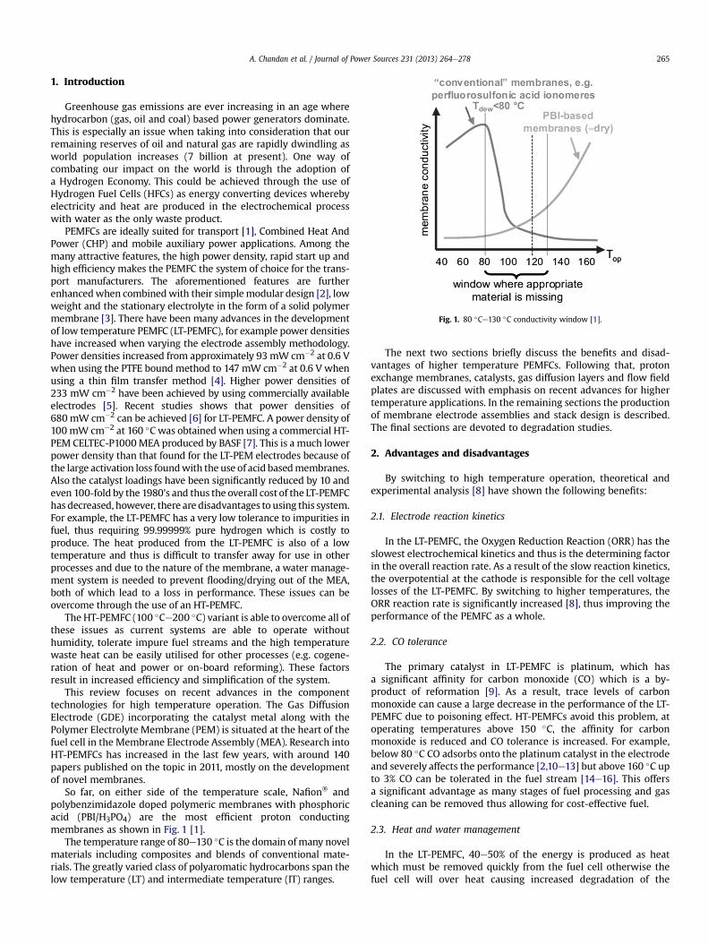
Fig. 1. 80 �Ce130 �C conductivity window [1].
A. Chandan et al. / Journal of Power Sources 231 (2013) 264e278 265
1. Introduction
Greenhouse gas emissions are ever increasing in an age wherehydrocarbon (gas, oil and coal) based power generators dominate.This is especially an issue when taking into consideration that ourremaining reserves of oil and natural gas are rapidly dwindling asworld population increases (7 billion at present). One way ofcombating our impact on the world is through the adoption ofa Hydrogen Economy. This could be achieved through the use ofHydrogen Fuel Cells (HFCs) as energy converting devices wherebyelectricity and heat are produced in the electrochemical processwith water as the only waste product.
PEMFCs are ideally suited for transport [1], Combined Heat AndPower (CHP) and mobile auxiliary power applications. Among themany attractive features, the high power density, rapid start up andhigh efficiency makes the PEMFC the system of choice for the trans-port manufacturers. The aforementioned features are furtherenhancedwhen combinedwith their simplemodular design [2], lowweight and the stationary electrolyte in the form of a solid polymermembrane [3]. There have been many advances in the developmentof low temperature PEMFC (LT-PEMFC), for example power densitieshave increased when varying the electrode assembly methodology.Power densities increased from approximately 93mW cm�2 at 0.6 Vwhen using the PTFE bound method to 147 mW cm�2 at 0.6 V whenusing a thin film transfer method [4]. Higher power densities of233 mW cm�2 have been achieved by using commercially availableelectrodes [5]. Recent studies shows that power densities of680 mW cm�2 can be achieved [6] for LT-PEMFC. A power density of100 mW cm�2 at 160 �C was obtained when using a commercial HT-PEM CELTEC-P1000MEA produced by BASF [7]. This is a much lowerpower density than that found for the LT-PEM electrodes because ofthe large activation loss foundwith the use of acid basedmembranes.Also the catalyst loadings have been significantly reduced by 10 andeven 100-fold by the 1980’s and thus the overall cost of the LT-PEMFChas decreased, however, there are disadvantages to using this system.For example, the LT-PEMFC has a very low tolerance to impurities infuel, thus requiring 99.99999% pure hydrogen which is costly toproduce. The heat produced from the LT-PEMFC is also of a lowtemperature and thus is difficult to transfer away for use in otherprocesses and due to the nature of the membrane, a water manage-ment system is needed to prevent flooding/drying out of the MEA,both of which lead to a loss in performance. These issues can beovercome through the use of an HT-PEMFC.
The HT-PEMFC (100 �Ce200 �C) variant is able to overcome all ofthese issues as current systems are able to operate withouthumidity, tolerate impure fuel streams and the high temperaturewaste heat can be easily utilised for other processes (e.g. cogene-ration of heat and power or on-board reforming). These factorsresult in increased efficiency and simplification of the system.
This review focuses on recent advances in the componenttechnologies for high temperature operation. The Gas DiffusionElectrode (GDE) incorporating the catalyst metal along with thePolymer Electrolyte Membrane (PEM) is situated at the heart of thefuel cell in the Membrane Electrode Assembly (MEA). Research intoHT-PEMFCs has increased in the last few years, with around 140papers published on the topic in 2011, mostly on the developmentof novel membranes.
So far, on either side of the temperature scale, Nafion� andpolybenzimidazole doped polymeric membranes with phosphoricacid (PBI/H3PO4) are the most efficient proton conductingmembranes as shown in Fig. 1 [1].
The temperature range of 80e130 �C is the domain ofmany novelmaterials including composites and blends of conventional mate-rials. The greatly varied class of polyaromatic hydrocarbons span thelow temperature (LT) and intermediate temperature (IT) ranges.
The next two sections briefly discuss the benefits and disad-vantages of higher temperature PEMFCs. Following that, protonexchange membranes, catalysts, gas diffusion layers and flow fieldplates are discussed with emphasis on recent advances for highertemperature applications. In the remaining sections the productionof membrane electrode assemblies and stack design is described.The final sections are devoted to degradation studies.
2. Advantages and disadvantages
By switching to high temperature operation, theoretical andexperimental analysis [8] have shown the following benefits:
2.1. Electrode reaction kinetics
In the LT-PEMFC, the Oxygen Reduction Reaction (ORR) has theslowest electrochemical kinetics and thus is the determining factorin the overall reaction rate. As a result of the slow reaction kinetics,the overpotential at the cathode is responsible for the cell voltagelosses of the LT-PEMFC. By switching to higher temperatures, theORR reaction rate is significantly increased [8], thus improving theperformance of the PEMFC as a whole.
2.2. CO tolerance
The primary catalyst in LT-PEMFC is platinum, which hasa significant affinity for carbon monoxide (CO) which is a by-product of reformation [9]. As a result, trace levels of carbonmonoxide can cause a large decrease in the performance of the LT-PEMFC due to poisoning effect. HT-PEMFCs avoid this problem, atoperating temperatures above 150 �C, the affinity for carbonmonoxide is reduced and CO tolerance is increased. For example,below 80 �C CO adsorbs onto the platinum catalyst in the electrodeand severely affects the performance [2,10e13] but above 160 �C upto 3% CO can be tolerated in the fuel stream [14e16]. This offersa significant advantage as many stages of fuel processing and gascleaning can be removed thus allowing for cost-effective fuel.
2.3. Heat and water management
In the LT-PEMFC, 40e50% of the energy is produced as heatwhich must be removed quickly from the fuel cell otherwise thefuel cell will over heat causing increased degradation of the

Table 1Targets for proton exchange membranes for transport application [25,26].
Characteristic 2015 Target
Maximum operating temperature 120 �CUnassisted start up from temperature �40 �CConductivity 0.1 S cm�1 (120 �C)
0.07 S cm�1 (Ambient temperature)0.01 S cm�1 (�20 �C)
Area specific resistance 0.02 U cm2
Relative humidity/inlet watervapour partial pressure
50%/1.5 kPa
Hydrogen/oxygen crossover at 1 atm 2 mA cm�2
Cost 20 US$/m2
Durability with cycling 5000 h
A. Chandan et al. / Journal of Power Sources 231 (2013) 264e278266
materials. As the operating temperature of the PEMFC is increased,the heat transfer rate increases as there is a larger temperaturegradient between the fuel cell and the external environment. For anLT-PEMFC system, the heat removal using existing radiator tech-nology found in transport vehicles is often insufficient. As a result,specialised cooling technology is required, all of which adds to theBalance of Plant (BoP) costs associated with the PEMFC. Increasingthe temperature of the PEMFC will allow for existing coolingarchitectures present in transport vehicles to be used thusincreasing the weight and mass specific energy densities and theoverall energy efficiency. The efficiency can be further increasedwhen cogeneration [17] and on-board reforming [8,14] areconsidered.
When operating at lower temperature (80 �C or less) underatmospheric pressure a dual phase water system is present in thefuel cell. This dual phase water systemmust be kept in tight controldue to the stringent humidification requirements of the membrane,which makes water management difficult. Higher operatingtemperatures mean that water management is simplified signifi-cantly as there is only a single (gaseous) phase present. This meansthat the transport of water in the membrane, electrodes anddiffusion layer is easier and flow field plate design can be greatlysimplified [10,11,13]. Another effect of the higher temperatures isthat the reactant and product gases are expected to have increaseddiffusion rates [9] and with no liquid water present to block theelectrochemically active surface area thus allowing for more reac-tions to occur. Both the simplified heat and water managementmean that much simpler flow field designs can be used whichshould help decrease the overall cost of the stack as machiningplates should be cheaper.
2.4. Alternative catalysts
Due to the increased electrode kinetics at higher temperatures,it becomes possible to utilise alternative catalysts [12] at theelectrodes, thus significantly reducing the cost of the PEMFC. Forexample, due to the higher temperatures, iron (Fe) may be used asa catalyst to facilitate the reactions [18]. Other work has beenperformed with the use of cobalt (Co) as a catalyst for the fuelcell [19].
Fig. 2. CO coverage on a platinum surface at a hydrogen pressure of 0.5 bar. Differentconcentrations of CO is shown [13].
3. Disadvantages
Many years have been devoted to optimising the low temper-ature technology and each component within the PEMFC. Forexample, GDE, MEA, gaskets, bipolar plates and the rest of the BoPhave been optimised for operation up to 80 �C; still, however manyissues remain unresolved. When temperature exceeds 100 �Cdehydration of conventional membranes, which require humidifi-cation to aid proton conductivity, is experienced. This yields largeohmic losses, lower operating cell voltages and power densities[20]. Acidebase HT membranes, for example phosphoric aciddoped PBI type materials, are thought to be a way of addressingdehydration issues; however, acid leaching from these materialsleads to serious degradation of the fuel cell components. This inturn affects the power density and the performance/efficiency ofthe fuel cell. The other concern which could affect commercialviability is the increased start-up time (up to 40min in some cases).The high temperature fuel cell must slowly be brought up to itsoperating temperature which could mean waiting for half an hourafter start-up before any current can be drawn. As the averagedriving range is only around 23 miles per day in the UK (based on2009 data), this would rule out HT-PEMFC use for any shortdistance driving [21].
4. Progress towards high temperature operations
4.1. Membranes
4.1.1. TargetsThe main objectives for all researchers in the development of
novel membrane materials are to increase the performance anddurability and to reduce the overall cost of fuel cells [22]. Table 1lists the 2015 US DOE targets for HT-PEM materials. The targetsincorporate the most important characteristics for PEMs, i.e. highconductivity, good thermal, mechanical and chemical stability,acceptable durability, compatibility with other fuel cell compo-nents, materials that are easy to work with and that can be recycledin an environmentally friendly manner [2,23,24].
Although the DoE target temperature is 120 �C, manyresearchers are aiming for temperatures up to 200 �C as increasedtemperature leads to increased CO tolerance of the electrocatalyst[13]. CO tolerance is understood to mean operation in the pres-ence of CO with voltage loss at the hydrogen electrode of less than10e20 mV [13]. CO tolerance is related to the thermodynamics ofcompetitive CO and H2 adsorption (and fractional coverage, q) onthe platinum surface of the catalyst. Fig. 2 shows the fractionalcoverage for different concentrations of CO at varying tempera-ture. It has been shown that qCO should be below 0.9 for tolerance.The dissociative adsorption of H2 becomes more thermodynami-cally beneficial at higher temperatures than the associativeadsorption of CO so at higher temperatures enough hydrogen isadsorbing on platinum sites for adequate hydrogen reduction.
A 2005 cost analysis [27] of an 80 kW HT-PEMFC system pro-jected a cost of 56 US $/kW for the MEA, assuming production of500,000 units which represents 83% of the cost of the stack. In 2009
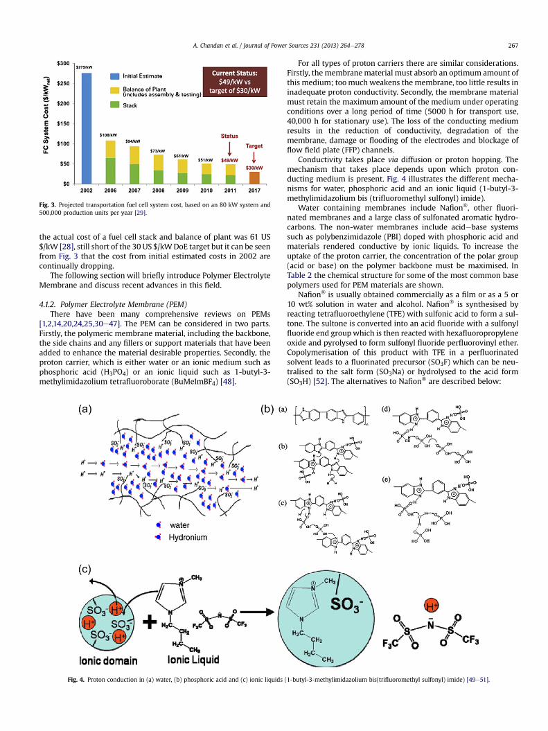
Fig. 3. Projected transportation fuel cell system cost, based on an 80 kW system and500,000 production units per year [29].
A. Chandan et al. / Journal of Power Sources 231 (2013) 264e278 267
the actual cost of a fuel cell stack and balance of plant was 61 US$/kW [28], still short of the 30 US $/kWDoE target but it can be seenfrom Fig. 3 that the cost from initial estimated costs in 2002 arecontinually dropping.
The following section will briefly introduce Polymer ElectrolyteMembrane and discuss recent advances in this field.
4.1.2. Polymer Electrolyte Membrane (PEM)There have been many comprehensive reviews on PEMs
[1,2,14,20,24,25,30e47]. The PEM can be considered in two parts.Firstly, the polymeric membrane material, including the backbone,the side chains and any fillers or support materials that have beenadded to enhance the material desirable properties. Secondly, theproton carrier, which is either water or an ionic medium such asphosphoric acid (H3PO4) or an ionic liquid such as 1-butyl-3-methylimidazolium tetrafluoroborate (BuMeImBF4) [48].
Fig. 4. Proton conduction in (a) water, (b) phosphoric acid and (c) ionic liquids (
For all types of proton carriers there are similar considerations.Firstly, the membranematerial must absorb an optimum amount ofthis medium; toomuch weakens themembrane, too little results ininadequate proton conductivity. Secondly, the membrane materialmust retain the maximum amount of the medium under operatingconditions over a long period of time (5000 h for transport use,40,000 h for stationary use). The loss of the conducting mediumresults in the reduction of conductivity, degradation of themembrane, damage or flooding of the electrodes and blockage offlow field plate (FFP) channels.
Conductivity takes place via diffusion or proton hopping. Themechanism that takes place depends upon which proton con-ducting medium is present. Fig. 4 illustrates the different mecha-nisms for water, phosphoric acid and an ionic liquid (1-butyl-3-methylimidazolium bis (trifluoromethyl sulfonyl) imide).
Water containing membranes include Nafion�, other fluori-nated membranes and a large class of sulfonated aromatic hydro-carbons. The non-water membranes include acidebase systemssuch as polybenzimidazole (PBI) doped with phosphoric acid andmaterials rendered conductive by ionic liquids. To increase theuptake of the proton carrier, the concentration of the polar group(acid or base) on the polymer backbone must be maximised. InTable 2 the chemical structure for some of the most common basepolymers used for PEM materials are shown.
Nafion� is usually obtained commercially as a film or as a 5 or10 wt% solution in water and alcohol. Nafion� is synthesised byreacting tetrafluoroethylene (TFE) with sulfonic acid to form a sul-tone. The sultone is converted into an acid fluoride with a sulfonylfluoride end groupwhich is then reactedwith hexafluoropropyleneoxide and pyrolysed to form sulfonyl fluoride perfluorovinyl ether.Copolymerisation of this product with TFE in a perfluorinatedsolvent leads to a fluorinated precursor (SO3F) which can be neu-tralised to the salt form (SO3Na) or hydrolysed to the acid form(SO3H) [52]. The alternatives to Nafion� are described below:
1-butyl-3-methylimidazolium bis(trifluoromethyl sulfonyl) imide) [49e51].
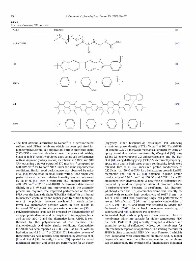
Table 2Structures of common PEM materials.
Name Structure Ref
Nafion�/PFSA [147]
PBI [8]
SPEEK [148]
SPI [149]
SPSU [150]
A. Chandan et al. / Journal of Power Sources 231 (2013) 264e278268
� The first obvious alternative to Nafion� is a perfluorinatedsulfonic acid (PFSA) membrane which has been optimised forhigh temperature fuel cell application. Various short side chain(SSC) PFSAs have been developed over the years and notably,Stassi et al. [53] recently obtained good single cell performancewith an Aquivion (Solvay Solexis) membrane at 130 �C and 100%RH obtaining a power output of 870 mW cm�2 compared to620 mW cm�2 for Nafion� N112 under the same experimentalconditions. Similar good performance was observed by Aricoet al. [54] for Aquivion in small stack testing. Good single cellperformance at reduced relative humidity was also observedby Tu et al. [55] with a composite SSC ionomer achieving488 mW cm�2 at 95 �C and 40%RH. Performance deterioratedslightly in a 5 kV stack and improvements in the assemblyprocess are required. The improved performance of the SSCPFSA over the long side chain PFSA (like Nafion�) is attributedto increased crystallinity and higher glass transition tempera-ture of the polymer. Increased mechanical strength makeslower EW membranes possible which in turn results inincreased IEC and proton charge carrier concentration [56].
� Polybenzimidazole (PBI) can be prepared by polymerisation ofan appropriate diamine and carboxylic acid in polyphosphoricacid at 180e200 �C and the alternative form, ABPBI, is syn-thesised by the polymerisation of the diamine 3,4-diamonobenzoic acid under similar conditions. Conductivityfor ABPBI has been reported as 0.08 S cm�1 at 140 �C with nohydration and 0.2 S cm�1 at 20%RH [57]. Extensive reviews ofthese materials have recently been published by Assensio et al.[8] and Li et al. [58]. Recently, Lin et al. [59] reported increasedmechanical strength and single cell performance for an epoxy
(diglycidyl ether bisphenol-A) crosslinked PBI achievinga maximum power density of 172 mW cm�2 at 160 �C and 0%RH(at around 0.25 V). Increased mechanical strength by using anepoxy cross-linker has been confirmed byWang et al. [60] using1,3-bis(2,3-epoxypropoxy)-2,2-dimethylpropane and by Hanet al. [61] using 4,40-diglycidyl (3,30,5,50-tetramethylbiphenyl)epoxy resin and in both cases proton conductivity levels wereretained. Kim et al. [62] measured proton conductivity of0.12 S cm�1 at 150 �C at 0%RH for a benzoxazine cross-linked PBImembrane and Aili et al. [63] obtained in-plane protonconductivity of 0.14 S cm�1 at 150 �C and 20%RH for a PBIcrosslinked with divinylsulfone. A new type of sulfonated PBIprepared by random copolymerisation of disodium 4,6-bis(4-carboxyphenoxy) benzene-1,3-disulfonate, 4,4_-dicarbox-ydiphenyl ether and 3,3_-diaminobenzidine was recently re-ported with relatively high conductivity of 0.037 S cm�1 at170 �C and 0 %RH (and promising single cell performance ofaround 300 mW cm�2) [64] and impressive conductivity of0.376 S cm�1 180 �C and 0%RH was reported by Mader andBenicewicz [65,66] for a block copolymer consisting ofsulfonated and non-sulfonated PBI segments.
� Sulfonated hydrocarbon polymers form another class ofmembranes which are suitable for higher temperature PEMfuel cells. Park et al. [46] recently compiled a detailed andextensive review of sulfonated hydrocarbon membranes forintermediate temperature application. The startingmaterial forSPEEK is often commercial PEEK (Victrex or Fumatech) which isthen sulfonated with concentrated sulphuric acid. A higherdegree of control over the sulfonation level in the membranecan be achieved by the synthesis of a functionalised monomer
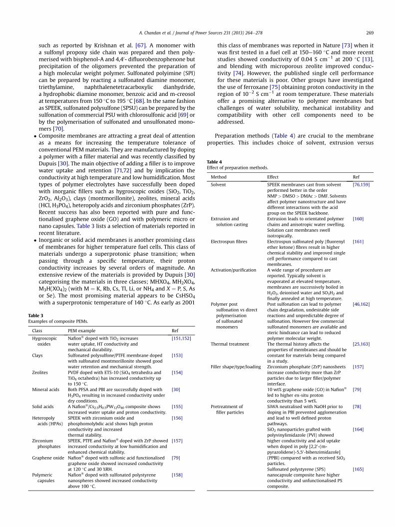
Table 4Effect of preparation methods.
Method Effect Ref
Solvent SPEEK membranes cast from solventperformed better in the orderNMP > DMSO > DMAc > DMF. Solventsaffect polymer nanostructure and havedifferent interactions with the acidgroup on the SPEEK backbone.
[76,159]
Extrusion andsolution casting
Extrusion leads to orientated polymerchains and anisotropic water swelling.Solution cast membranes swellisotropically.
[160]
Electrospun fibres Electrospun sulfonated poly (fluorenylether ketone) fibres result in higherchemical stability and improved singlecell performance compared to castmembranes.
[161]
Activation/purification A wide range of procedures arereported. Typically solvent isevaporated at elevated temperature,membranes are successively boiled inH2O2, deionised water and SO3H2 andfinally annealed at high temperature.
Polymer post Post sulfonation can lead to polymer [46,162]
A. Chandan et al. / Journal of Power Sources 231 (2013) 264e278 269
such as reported by Krishnan et al. [67]. A monomer witha sulfonyl propoxy side chain was prepared and then poly-merised with bisphenol-A and 4,40- difluorobenzophenone butprecipitation of the oligomers prevented the preparation ofa high molecular weight polymer. Sulfonated polyimine (SPI)can be prepared by reacting a sulfonated diamine monomer,triethylamine, naphthalenetetracarboxylic dianhydride,a hydrophobic diamine monomer, benzoic acid and m-creosolat temperatures from 150 �C to 195 �C [68]. In the same fashionas SPEEK, sulfonated polysulfone (SPSU) can be prepared by thesulfonation of commercial PSU with chlorosulfonic acid [69] orby the polymerisation of sulfonated and unsulfonated mono-mers [70].
� Composite membranes are attracting a great deal of attentionas a means for increasing the temperature tolerance ofconventional PEMmaterials. They are manufactured by dopinga polymer with a filler material and was recently classified byDupuis [30]. The main objective of adding a filler is to improvewater uptake and retention [71,72] and by implication theconductivity at high temperature and low humidification. Mosttypes of polymer electrolytes have successfully been dopedwith inorganic fillers such as hygroscopic oxides (SiO2, TiO2,ZrO2, Al2O3), clays (montmorillonite), zeolites, mineral acids(HCl, H3PO4), heteropoly acids and zirconium phosphates (ZrP).Recent success has also been reported with pure and func-tionalised graphene oxide (GO) and with polymeric micro ornano capsules. Table 3 lists a selection of materials reported inrecent literature.
� Inorganic or solid acid membranes is another promising classof membranes for higher temperature fuel cells. This class ofmaterials undergo a superprotonic phase transition; whenpassing through a specific temperature, their protonconductivity increases by several orders of magnitude. Anextensive review of the materials is provided by Dupuis [30]categorising the materials in three classes; MHXO4, MH2XO4,M3H(XO4)2 (with M ¼ K, Rb, Cs, Tl, Li, or NH4 and X ¼ P, S, Asor Se). The most promising material appears to be CsHSO4with a superprotonic temperature of 140 �C. As early as 2001
Table 3Examples of composite PEMs.
Class PEM example Ref
Hygroscopicoxides
Nafion� doped with TiO2 increaseswater uptake, HT conductivity andmechanical durability.
[151,152]
Clays Sulfonated polysulfone/PTFE membrane dopedwith sulfonated montmorillonite showed goodwater retention and mechanical strength.
[153]
Zeolites PVDF doped with ETS-10 (SiO4 tetrahedra andTiO6 octahedra) has increased conductivity upto 150 �C.
[154]
Mineral acids Both PFSA and PBI are successfully doped withH3PO4 resulting in increased conductivity underdry conditions.
[30]
Solid acids A Nafion�/Cs2.5H0.5PW12O40 composite showsincreased water uptake and proton conductivity.
[155]
Heteropolyacids (HPAs)
SPEEK with zirconium oxide andphosphomolybdic acid shows high protonconductivity and increasedthermal stability.
[156]
Zirconiumphosphates
SPEEK, PTFE and Nafion� doped with ZrP showedincreased conductivity at low humidification andenhanced chemical stability.
[157]
Graphene oxide Nafion� doped with sulfonic acid functionalisedgraphene oxide showed increased conductivityat 120 �C and 30 %RH.
[79]
Polymericcapsules
Nafion� doped with sulfonated polystyrenenanospheres showed increased conductivityabove 100 �C.
[158]
this class of membranes was reported in Nature [73] when itwas first tested in a fuel cell at 150e160 �C and more recentstudies showed conductivity of 0.04 S cm�1 at 200 �C [13],and blending with microporous zeolite improved conduc-tivity [74]. However, the published single cell performancefor these materials is poor. Other groups have investigatedthe use of ferroxane [75] obtaining proton conductivity in theregion of 10�2 S cm�1 at room temperature. These materialsoffer a promising alternative to polymer membranes butchallenges of water solubility, mechanical instability andcompatibility with other cell components need to beaddressed.
Preparation methods (Table 4) are crucial to the membraneproperties. This includes choice of solvent, extrusion versus
sulfonation vs directpolymerisationof sulfonatedmonomers
chain degradation, undesirable sidereactions and unpredictable degree ofsulfonation. However few commercialsulfonated monomers are available andsteric hindrance can lead to reducedpolymer molecular weight.
Thermal treatment The thermal history affects theproperties of membranes and should beconstant for materials being comparedin a study.
[25,163]
Filler shape/type/loading Zirconium phosphate (ZrP) nanosheetsincrease conductivity more than ZrPparticles due to larger filler/polymerinterface.
[157]
10 wt% graphene oxide (GO) in Nafion�
led to higher ex-situ protonconductivity than 5 wt%.
[79]
Pretreatment offiller particles
SiWA neutralised with NaOH prior todoping in PBI prevented agglomerationand lead to well defined protonpathways.
[78]
SiO2 nanoparticles grafted withpolyvinylimidazole (PVI) showedhigher conductivity and acid uptakewhen doped in poly [2,20-(m-pyrazolidene)-5,50-bibenzimidazole](PPBI) compared with as received SiO2
particles.
[164]
Sulfonated polystyrene (SPS)nanocapsule composite have higherconductivity and unfunctionalised PScomposite.
[165]

Table 5Summary of potential high temperature membrane materials.
Membrane material Conductivity/Temp/%RH Ref
Nafion�/(5 wt%) SPPSQ* 0.157 S cm�1 at 120 �C and 100%RH
[166]
PBI/H3PO4/(40%) SiWA 0.177 S cm�1 at 150 �C and 0%RH
[78]
Recast Nafion� ** 0.002 S cm�1 at 130 �C and 100%RH
[167]
Nafion� * 0.035 S cm�1 at 120 �C and 30%RH
[168]
Nafion� 117/(20 wt%) ZrSPP 0.1 S cm�1 at 100 �C and 90 %RH [169]Recast Nafion�/(20 wt%) ZrSPP* 0.05 S cm�1 at 110 �C and 98 %
RH[170]
Recast Nafion� */SGO 0.047 S cm�1 at 130 �C and 30%RH
[168]
SPEEK-WC 0.00022 S cm�1 at 96 �C and 85%RH
[171]
SPEEK-WC/SiW (9.6 wt%) 0.0013 S cm�1 at 96 �C and 85%RH
[171]
SPEEK/poly(imi-alt-CTFE) 0.001e0.015 S cm�1 at 120 �Cand 25e95 %RH
[172]
SPEEK/ZrPeNS) 0.079 S cm�1 at 150 �C and 100%RH
[157]
SPI with fluorene groups 1.67 S cm�1 at 120 �C and 100%RH
[149]
SPI with fluorene groups 0.003 S cm�1 at 160 �C and 12%RH
[173]
SPI with sulfophenoxypropoxypendants
1 S cm�1 at 120 �C at 100 %RH [174]
SPU with fluorene 0.5 S cm�1 at 110 �C and 50 %RH [175]CF6ePBI 0.12 S cm�1 at 175 �C and 10
%RH[109]
SO2ePBI 0.12 S cm�1 at 180 �C and 5%RH [176]PBI/SPAES 0.045 S cm�1 at 200 �C no
external humidification[177]
PSU with pyridine andhydroquinone groups
0.02 S cm�1 at 120 �C 0 %RH [23]
72TEOSe18PDMSe10PO(OCH3)3/40%[EMI][TFSI]
0.00487 S cm�1 150 �C 0 %RH [178]
TMOSeTMPSeTEP/(40%)BMIMBF4
0.006 S cm�1 150 �C 0 %RH [179]
30TMOSe30TEOSe30MTEOSe10PO(OCH3)3/(40%)EMIMBF4
0.01 S cm�1 155 �C 0 %RH [180]
60TMOSe30VTMOSe10PO(OCH3)3/(40%)EMIMBF4
0.0089 S cm�1 155 �C 0 %RH [180]
*Membrane cast from 5 wt% Nafion� 1100 solution, DuPont. **Membrane cast fromNafion� resin, Shandong Dongyue Polymer Material Co. Ltd.
A. Chandan et al. / Journal of Power Sources 231 (2013) 264e278270
casting and thermal post-treatment [56,76]. When inorganicadditives are used, the preparation of the additive as well as thecomposite membrane materials are crucial to the performance ofthe materials [71].
Fig. 5. Single cell conductivity of PBI doped with various loadings of silicotungstic
Table 5 summarises data on promising high temperaturemembrane materials and the entries that are highlighted have metDoE targets for 2015.
It is clear that various materials exist which satisfy either hightemperature or low humidity requirements, but that fewer exist thatsatisfyboth requirementsat thesametime.Anhydrousmaterials suchas polybenzimidazole show the best potential for high temperatureapplication and hydrated materials, such as polysulfones and poly-imides would be best suited for intermediate application.
Both temperature ranges show benefits and drawbacks. Theanhydrous materials like PBI offer high current densities at hightemperature (Fig. 5) but concerns remain regarding low tempera-ture operation, acid leaching and the long start-up time. Recentlyhowever, an innovative method of imbibing the conductive phos-phoric acid via the electrodes and gas diffusion layers (rather thandoping the PBI membrane) has shown promising fast start-upresults. Wannek et al. [57,77] reported a power density of120 mW at 600 mV after only 11 min of operation for an ABPBImembrane.
The highly specialised new fluorinated and polyaromatic hydro-carbon materials show promising high temperature conductivity(Fig. 6) but the humidity requirement adds cost and complication tothe balance of plant. This could be acceptable if the power output issignificantly increased and if long term thermal, chemical andmechanical durability can be shown through in-situ testing.
4.2. Catalysts
Within the LT-PEMFC, one aspect that has received a lot ofattention is the catalyst layer. This is potentially one of the biggestchallenges for the widespread usage of PEMFC technology ascurrently the catalyst layer within the PEMFC contains platinum,a PGM (Platinum Group Metal). The DOE have set targets for thePGM loading in the stack for 2015 (see Table 6 [81]). The degra-dation of the platinum is common when the fuel cell is used forextended periods of time [82]. In PEMFC systems, the catalyst layeris a complex structure that consists of support material (carbonblack) and an ionomer (Nafion�) for proton conduction. This layermust be sufficiently porous for the removal of waste water andtransport of the reactant gases.
One of the major issues with using platinum as a catalyst is itspropensity to degrade. There are three main mechanisms that arewidely accepted as being the methods of degradations: (i) thecarbon supports corrode [83]; (ii) the platinum particles dissolve,leading to particle growth via Ostwald ripening, when the platinumis deposited [84]; (iii) the platinum particles agglomerate andsinter together on the carbon support via passive diffusionprocesses [85]. Novel methods for LT-PEMFC catalyst layer fabri-cation to increase active platinum surface area and thus decrease
acid. Temperatures (a) 120, (b) 150 and (c) 180 �C all with dry fuel gas [78].

Fig. 6. Power curves showing the performance of Nafion� e GO composite membrane (left) [79] and poly(arylene ether sulfone ketone) with optimised Nafion� free MEA [79,80].
A. Chandan et al. / Journal of Power Sources 231 (2013) 264e278 271
overall platinum levels are demonstrated by Curnick et al. [86].They found that, by using the ionomer (Nafion�) as a surfactant,they were able to stabilise the platinum particles by both steric andelectrostatic mechanism (see Fig. 7 [86]). They also found that theycould achieve good interfacial contact between these two phases,which remained upon adding the carbon support. This wasadvantageous because it led to a highly effective distribution ofNafion� ionomer allowing for good contact between the platinumand the proton conducting network (allowing for 90% utilization ofplatinum) [86]. Further research would be required to see whetherit is possible to utilise the same techniques using the hightemperature PBI based membrane ionomers and to see if this willallow for such a high level of platinum utilisation.
It may also be possible to use alternative catalysts to platinumdue to the increased reaction kinetics (due to the increased oper-ating temperatures). There are other metals that are able to catalysethe ORR, for example iron and cobalt. Villers et al. [18] havedemonstrated that the catalyst supportmaterial plays a large role inthe catalytic activity. Interestingly, they found for an LT-PEMFCsystem, that the nitrogen content on the surface of the catalysthad a large effect on the catalytic activity of the iron. It is alsopossible to use platinum based binary electrocatalyst alloys such asPtFe, PtCo, PtNi, PtCr and Pt/RuO2eSiOx which exhibit much highercatalytic activity than pure Pt for the ORR reactions [87e89].Recently, platinum based binary electrocatalyst were also tested forHT-PEMFC conditions, such as, Pt/SnOx [90] and PtCo [54]. It wasfound that the use of these catalyst layers enhance the stability andperformance of the fuel cell at HT operating conditions.
4.3. Gas diffusion layer and flow field plates
The porous GDL plays an essential role to assist the reactions onthe catalyst layer by diffusing the reactants from the flow channelsto reach the active sites on the catalyst. It also enhances humidi-fication in the membrane by allowing water vapour to diffuse alongwith the reactants. At the same time liquid water produced on the
Table 6US DOE targets for PGM loading in the stack.
Characteristics Units Stack targets
2010 2015
PGM total content(both electrode)
g/kW (rated) 0.3 0.2
PGM total loading mg PGM/cm�2 electrode area 0.3 0.2
cathode can flow out of the cell to prevent water flooding andblocking of the active sites on the catalyst [42]. However, no liquidwater is expected to be present when operating at temperaturesover 100 �C, therefore, the demand on GDL properties for watertransport at high temperature is reduced. The GDL offers a sup-porting structure for the catalyst layer and links the catalystparticles electronically. It is an electrically conducting medium thattransfers electrons between the catalyst layer and the bipolar plate[91]. State of the art GDLmaterials seem to be used for both lowandhigh temperature PEMFCs. Table 7 shows some types of GDLs usedin HT-PEMFCs in literature. To the authors knowledge, only onepaper has been found in the literature on GDLs for high tempera-ture, i.e., Lobato et al. [92] which studied the effect of PTFE loadingin the GDL on PBI-based PEM fuel cell. It was reported that lowerPTFE loading results in a higher cell performance but it hasa negative effect on the mechanical properties of the GDL and a 10%PTFE loading is suggested as an optimumvalue for HT PEM. Furtherwork is required to optimize GDL properties for HT-PEM fuel cells.
The Flow Field Plate (FFP) supplies and distributes the reactantsover the GDL, removes water, collects current, and providesmechanical support for the cell or stack. The DOE have set targetsfor 2015 for the FPP (see Table 8 [81]). Graphite plates have beentraditionally used in fuel cells because of their chemical stabilityand high electrical conductivity, whichmakes them suitable for HT-PEMFC. Metallic plates are considered superior alternatives forgraphite plates due to the reduction in cost, increased volumetricpower density and higher mechanical strength [93]. The hightemperature cell operation prevents the formation of liquid waterin the cell, therefore, allows the use of a wider range of flow fielddesigns without facing the water management problem. The effectof flow field designs for HT-PEM has been studied both experi-mentally [7] and by modelling [94,95]. These studies show thesignificant effect of flow field design on the performance, andfocuses on the pressure and current distribution over the surface ofthe cell. There are different configurations of flow channel, all ofwhich are machined onto the FFP plates. These various configura-tions have been studied in an attempt to find an optimum designfor fuel cell operation. Parallel [15,96], single serpentine [97e103],multiple serpentine [104], etc. are the most common designs usedin PEMFC.
Temperature increase enhances the degradation process andputs higher demand on the material stability. Recently, Hartniget al. [105] studied the effect of bipolar plate degradation in a hightemperature acid based fuel cell on the overall performance; thestudy shows a significant effect of the material surface morphology
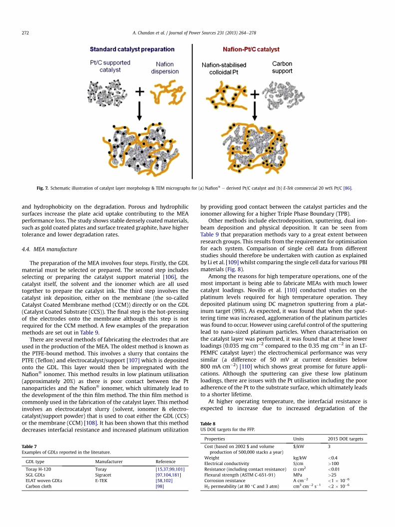
Fig. 7. Schematic illustration of catalyst layer morphology & TEM micrographs for (a) Nafion� e derived Pt/C catalyst and (b) E-Tek commercial 20 wt% Pt/C [86].
Table 8US DOE targets for the FFP.
A. Chandan et al. / Journal of Power Sources 231 (2013) 264e278272
and hydrophobicity on the degradation. Porous and hydrophilicsurfaces increase the plate acid uptake contributing to the MEAperformance loss. The study shows stable densely coated materials,such as gold coated plates and surface treated graphite, have highertolerance and lower degradation rates.
4.4. MEA manufacture
The preparation of the MEA involves four steps. Firstly, the GDLmaterial must be selected or prepared. The second step includesselecting or preparing the catalyst support material [106], thecatalyst itself, the solvent and the ionomer which are all usedtogether to prepare the catalyst ink. The third step involves thecatalyst ink deposition, either on the membrane (the so-calledCatalyst Coated Membrane method (CCM)) directly or on the GDL(Catalyst Coated Substrate (CCS)). The final step is the hot-pressingof the electrodes onto the membrane although this step is notrequired for the CCM method. A few examples of the preparationmethods are set out in Table 9.
There are several methods of fabricating the electrodes that areused in the production of the MEA. The oldest method is known asthe PTFE-bound method. This involves a slurry that contains thePTFE (Teflon) and electrocatalyst/support [107] which is depositedonto the GDL. This layer would then be impregnated with theNafion� ionomer. This method results in low platinum utilisation(approximately 20%) as there is poor contact between the Ptnanoparticles and the Nafion� ionomer, which ultimately lead tothe development of the thin film method. The thin film method iscommonly used in the fabrication of the catalyst layer. This methodinvolves an electrocatalyst slurry (solvent, ionomer & electro-catalyst/support powder) that is used to coat either the GDL (CCS)or the membrane (CCM) [108]. It has been shown that this methoddecreases interfacial resistance and increased platinum utilization
Table 7Examples of GDLs reported in the literature.
GDL type Manufacturer Reference
Toray H-120 Toray [15,37,99,101]SGL GDLs Sigracet [97,104,181]ELAT woven GDLs E-TEK [58,102]Carbon cloth [98]
by providing good contact between the catalyst particles and theionomer allowing for a higher Triple Phase Boundary (TPB).
Other methods include electrodeposition, sputtering, dual ion-beam deposition and physical deposition. It can be seen fromTable 9 that preparation methods vary to a great extent betweenresearch groups. This results from the requirement for optimisationfor each system. Comparison of single cell data from differentstudies should therefore be undertaken with caution as explainedby Li et al. [109] whilst comparing the single cell data for various PBImaterials (Fig. 8).
Among the reasons for high temperature operations, one of themost important is being able to fabricate MEAs with much lowercatalyst loadings. Novillo et al. [110] conducted studies on theplatinum levels required for high temperature operation. Theydeposited platinum using DC magnetron sputtering from a plat-inum target (99%). As expected, it was found that when the sput-tering time was increased, agglomeration of the platinum particleswas found to occur. However using careful control of the sputteringlead to nano-sized platinum particles. When characterisation onthe catalyst layer was performed, it was found that at these lowerloadings (0.035 mg cm�2 compared to the 0.35 mg cm�2 in an LT-PEMFC catalyst layer) the electrochemical performance was verysimilar (a difference of 50 mV at current densities below800 mA cm�2) [110] which shows great promise for future appli-cations. Although the sputtering can give these low platinumloadings, there are issues with the Pt utilisation including the pooradherence of the Pt to the substrate surface, which ultimately leadsto a shorter lifetime.
At higher operating temperature, the interfacial resistance isexpected to increase due to increased degradation of the
Properties Units 2015 DOE targets
Cost (based on 2002 $ and volumeproduction of 500,000 stacks a year)
$/kW 3
Weight kg/kW <0.4Electrical conductivity S/cm >100Resistance (including contact resistance) U cm2 <0.01Flexural strength (ASTM C-651-91) MPa >25Corrosion resistance A cm�2 <1 � 10�6
H2 permeability (at 80 �C and 3 atm) cm3 cm�2 s�1 <2 � 10�6
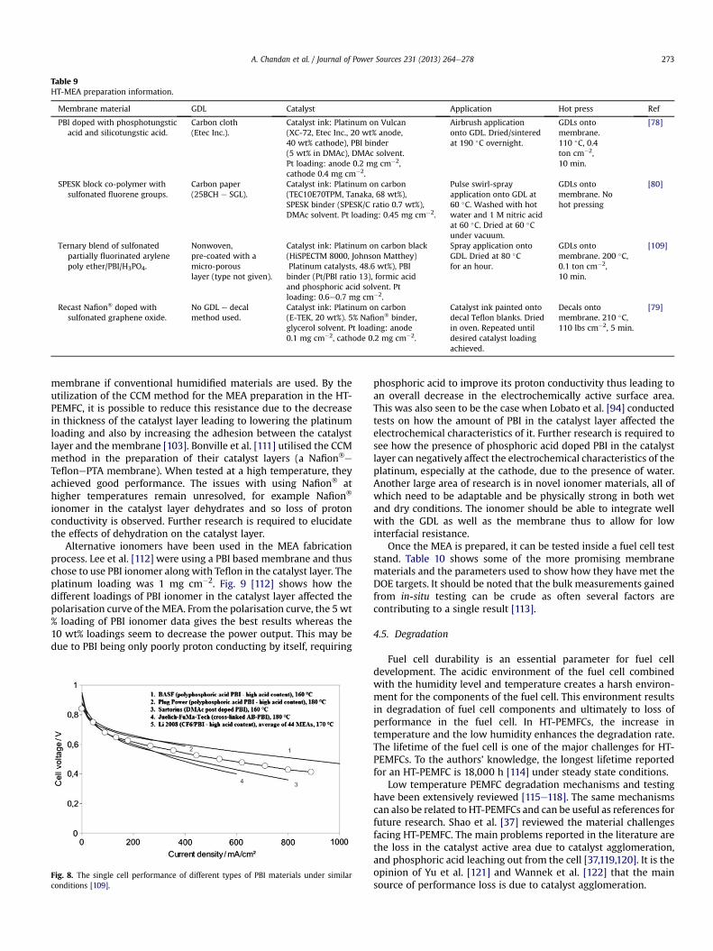
Table 9HT-MEA preparation information.
Membrane material GDL Catalyst Application Hot press Ref
PBI doped with phosphotungsticacid and silicotungstic acid.
Carbon cloth(Etec Inc.).
Catalyst ink: Platinum on Vulcan(XC-72, Etec Inc., 20 wt% anode,40 wt% cathode), PBI binder(5 wt% in DMAc), DMAc solvent.Pt loading: anode 0.2 mg cm�2,cathode 0.4 mg cm�2.
Airbrush applicationonto GDL. Dried/sinteredat 190 �C overnight.
GDLs ontomembrane.110 �C, 0.4ton cm�2,10 min.
[78]
SPESK block co-polymer withsulfonated fluorene groups.
Carbon paper(25BCH e SGL).
Catalyst ink: Platinum on carbon(TEC10E70TPM, Tanaka, 68 wt%),SPESK binder (SPESK/C ratio 0.7 wt%),DMAc solvent. Pt loading: 0.45 mg cm�2.
Pulse swirl-sprayapplication onto GDL at60 �C. Washed with hotwater and 1 M nitric acidat 60 �C. Dried at 60 �Cunder vacuum.
GDLs ontomembrane. Nohot pressing
[80]
Ternary blend of sulfonatedpartially fluorinated arylenepoly ether/PBI/H3PO4.
Nonwoven,pre-coated with amicro-porouslayer (type not given).
Catalyst ink: Platinum on carbon black(HiSPECTM 8000, Johnson Matthey)Platinum catalysts, 48.6 wt%), PBIbinder (Pt/PBI ratio 13), formic acidand phosphoric acid solvent. Ptloading: 0.6e0.7 mg cm�2.
Spray application ontoGDL. Dried at 80 �Cfor an hour.
GDLs ontomembrane. 200 �C,0.1 ton cm�2,10 min.
[109]
Recast Nafion� doped withsulfonated graphene oxide.
No GDL e decalmethod used.
Catalyst ink: Platinum on carbon(E-TEK, 20 wt%). 5% Nafion� binder,glycerol solvent. Pt loading: anode0.1 mg cm�2, cathode 0.2 mg cm�2.
Catalyst ink painted ontodecal Teflon blanks. Driedin oven. Repeated untildesired catalyst loadingachieved.
Decals ontomembrane. 210 �C,110 lbs cm�2, 5 min.
[79]
A. Chandan et al. / Journal of Power Sources 231 (2013) 264e278 273
membrane if conventional humidified materials are used. By theutilization of the CCM method for the MEA preparation in the HT-PEMFC, it is possible to reduce this resistance due to the decreasein thickness of the catalyst layer leading to lowering the platinumloading and also by increasing the adhesion between the catalystlayer and the membrane [103]. Bonville et al. [111] utilised the CCMmethod in the preparation of their catalyst layers (a Nafion�e
TeflonePTA membrane). When tested at a high temperature, theyachieved good performance. The issues with using Nafion� athigher temperatures remain unresolved, for example Nafion�
ionomer in the catalyst layer dehydrates and so loss of protonconductivity is observed. Further research is required to elucidatethe effects of dehydration on the catalyst layer.
Alternative ionomers have been used in the MEA fabricationprocess. Lee et al. [112] were using a PBI based membrane and thuschose to use PBI ionomer along with Teflon in the catalyst layer. Theplatinum loading was 1 mg cm�2. Fig. 9 [112] shows how thedifferent loadings of PBI ionomer in the catalyst layer affected thepolarisation curve of theMEA. From the polarisation curve, the 5wt% loading of PBI ionomer data gives the best results whereas the10 wt% loadings seem to decrease the power output. This may bedue to PBI being only poorly proton conducting by itself, requiring
Fig. 8. The single cell performance of different types of PBI materials under similarconditions [109].
phosphoric acid to improve its proton conductivity thus leading toan overall decrease in the electrochemically active surface area.This was also seen to be the case when Lobato et al. [94] conductedtests on how the amount of PBI in the catalyst layer affected theelectrochemical characteristics of it. Further research is required tosee how the presence of phosphoric acid doped PBI in the catalystlayer can negatively affect the electrochemical characteristics of theplatinum, especially at the cathode, due to the presence of water.Another large area of research is in novel ionomer materials, all ofwhich need to be adaptable and be physically strong in both wetand dry conditions. The ionomer should be able to integrate wellwith the GDL as well as the membrane thus to allow for lowinterfacial resistance.
Once the MEA is prepared, it can be tested inside a fuel cell teststand. Table 10 shows some of the more promising membranematerials and the parameters used to show how they have met theDOE targets. It should be noted that the bulk measurements gainedfrom in-situ testing can be crude as often several factors arecontributing to a single result [113].
4.5. Degradation
Fuel cell durability is an essential parameter for fuel celldevelopment. The acidic environment of the fuel cell combinedwith the humidity level and temperature creates a harsh environ-ment for the components of the fuel cell. This environment resultsin degradation of fuel cell components and ultimately to loss ofperformance in the fuel cell. In HT-PEMFCs, the increase intemperature and the low humidity enhances the degradation rate.The lifetime of the fuel cell is one of the major challenges for HT-PEMFCs. To the authors’ knowledge, the longest lifetime reportedfor an HT-PEMFC is 18,000 h [114] under steady state conditions.
Low temperature PEMFC degradation mechanisms and testinghave been extensively reviewed [115e118]. The same mechanismscan also be related to HT-PEMFCs and can be useful as references forfuture research. Shao et al. [37] reviewed the material challengesfacing HT-PEMFC. The main problems reported in the literature arethe loss in the catalyst active area due to catalyst agglomeration,and phosphoric acid leaching out from the cell [37,119,120]. It is theopinion of Yu et al. [121] and Wannek et al. [122] that the mainsource of performance loss is due to catalyst agglomeration.
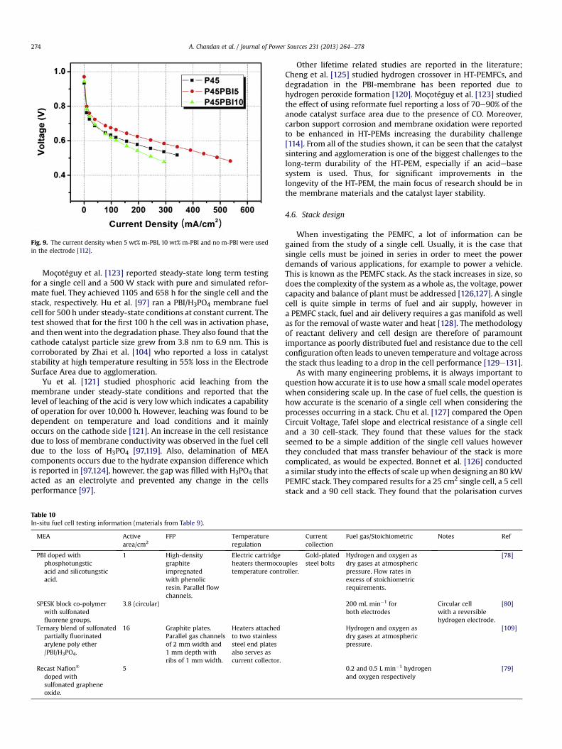
Fig. 9. The current density when 5 wt% m-PBI, 10 wt% m-PBI and no m-PBI were usedin the electrode [112].
A. Chandan et al. / Journal of Power Sources 231 (2013) 264e278274
Moçotéguy et al. [123] reported steady-state long term testingfor a single cell and a 500 W stack with pure and simulated refor-mate fuel. They achieved 1105 and 658 h for the single cell and thestack, respectively. Hu et al. [97] ran a PBI/H3PO4 membrane fuelcell for 500 h under steady-state conditions at constant current. Thetest showed that for the first 100 h the cell was in activation phase,and thenwent into the degradation phase. They also found that thecathode catalyst particle size grew from 3.8 nm to 6.9 nm. This iscorroborated by Zhai et al. [104] who reported a loss in catalyststability at high temperature resulting in 55% loss in the ElectrodeSurface Area due to agglomeration.
Yu et al. [121] studied phosphoric acid leaching from themembrane under steady-state conditions and reported that thelevel of leaching of the acid is very low which indicates a capabilityof operation for over 10,000 h. However, leaching was found to bedependent on temperature and load conditions and it mainlyoccurs on the cathode side [121]. An increase in the cell resistancedue to loss of membrane conductivity was observed in the fuel celldue to the loss of H3PO4 [97,119]. Also, delamination of MEAcomponents occurs due to the hydrate expansion difference whichis reported in [97,124], however, the gap was filled with H3PO4 thatacted as an electrolyte and prevented any change in the cellsperformance [97].
Table 10In-situ fuel cell testing information (materials from Table 9).
MEA Activearea/cm2
FFP Temperatureregulation
PBI doped withphosphotungsticacid and silicotungsticacid.
1 High-densitygraphiteimpregnatedwith phenolicresin. Parallel flowchannels.
Electric cartridgeheaters thermocoutemperature contr
SPESK block co-polymerwith sulfonatedfluorene groups.
3.8 (circular)
Ternary blend of sulfonatedpartially fluorinatedarylene poly ether/PBI/H3PO4.
16 Graphite plates.Parallel gas channelsof 2 mm width and1 mm depth withribs of 1 mm width.
Heaters attachedto two stainlesssteel end platesalso serves ascurrent collector.
Recast Nafion�
doped withsulfonated grapheneoxide.
5
Other lifetime related studies are reported in the literature;Cheng et al. [125] studied hydrogen crossover in HT-PEMFCs, anddegradation in the PBI-membrane has been reported due tohydrogen peroxide formation [120]. Moçotéguy et al. [123] studiedthe effect of using reformate fuel reporting a loss of 70e90% of theanode catalyst surface area due to the presence of CO. Moreover,carbon support corrosion and membrane oxidation were reportedto be enhanced in HT-PEMs increasing the durability challenge[114]. From all of the studies shown, it can be seen that the catalystsintering and agglomeration is one of the biggest challenges to thelong-term durability of the HT-PEM, especially if an acidebasesystem is used. Thus, for significant improvements in thelongevity of the HT-PEM, the main focus of research should be inthe membrane materials and the catalyst layer stability.
4.6. Stack design
When investigating the PEMFC, a lot of information can begained from the study of a single cell. Usually, it is the case thatsingle cells must be joined in series in order to meet the powerdemands of various applications, for example to power a vehicle.This is known as the PEMFC stack. As the stack increases in size, sodoes the complexity of the system as awhole as, the voltage, powercapacity and balance of plant must be addressed [126,127]. A singlecell is quite simple in terms of fuel and air supply, however ina PEMFC stack, fuel and air delivery requires a gas manifold as wellas for the removal of waste water and heat [128]. The methodologyof reactant delivery and cell design are therefore of paramountimportance as poorly distributed fuel and resistance due to the cellconfiguration often leads to uneven temperature and voltage acrossthe stack thus leading to a drop in the cell performance [129e131].
As with many engineering problems, it is always important toquestion how accurate it is to use how a small scale model operateswhen considering scale up. In the case of fuel cells, the question ishow accurate is the scenario of a single cell when considering theprocesses occurring in a stack. Chu et al. [127] compared the OpenCircuit Voltage, Tafel slope and electrical resistance of a single celland a 30 cell-stack. They found that these values for the stackseemed to be a simple addition of the single cell values howeverthey concluded that mass transfer behaviour of the stack is morecomplicated, as would be expected. Bonnet et al. [126] conducteda similar study into the effects of scale upwhen designing an 80 kWPEMFC stack. They compared results for a 25 cm2 single cell, a 5 cellstack and a 90 cell stack. They found that the polarisation curves
Currentcollection
Fuel gas/Stoichiometric Notes Ref
plesoller.
Gold-platedsteel bolts
Hydrogen and oxygen asdry gases at atmosphericpressure. Flow rates inexcess of stoichiometricrequirements.
[78]
200 mL min�1 forboth electrodes
Circular cellwith a reversiblehydrogen electrode.
[80]
Hydrogen and oxygen asdry gases at atmosphericpressure.
[109]
0.2 and 0.5 L min�1 hydrogenand oxygen respectively
[79]

A. Chandan et al. / Journal of Power Sources 231 (2013) 264e278 275
(see Fig. 10 [111]) for the three different sizes seemed to be inconcordance thus suggesting that a single cell can be used topredict stack behaviour. When studying the single cell and the 5cell stack in further detail, they found that the effect of fuel flowhadlittle effect on the cell voltages. Moving from single cell to stackoperation is favourable due to the possibilities for greater fueleconomy and power capabilities [127]. For LT-PEMFC systems, it isof paramount importance to have excellent water and thermalmanagement systems in place to accommodate the non-uniformityof the cell potential, reactant concentration and temperature [132].Theoretically, by switching to high temperature operation, thewater and thermal management should be easier as there is onlya single phase of water vapour and a more significant temperaturegradient.
In contrast, it has also been shown that a single cell cannot beused to predict the behaviour of a stack. Urbani et al. [133] foundthat the relative humidity at the anode and cathode causeda difference in the polarisation curves of a single cell and a 5 cellstack. When a high relative humidity was used at both the anodeand the cathode, they also found that the stack performancesuffered due to flooding of the cells. When the cell and stack wererun at 80 �C, fuel and air pressure were at 1.5 bar and a current of0.4 A cm�2 was drawn, they found an 8% decrease in the perfor-mance of the stack [111].
Another area where a single cell behaviour cannot be used topredict stack behaviour is heat management. Chu et al. [127] foundthis when studying a 30 cell stack. Due to the large number of cells,an even heating effect could not easily be applied to the cells andheat generated from the fuel cell reactions was very difficult toremove from the interior of the stack. This resulted in a differenceof 26 �C from the interior of the stack to the exterior.
Very little work has been conducted into whether or not an HT-PEM single cell results will allow for accurate prediction of thebehaviour of a stack. In particular, the fact that there will be simplerwater and heat management will mean that small scale studiesshould have greater validity as the mass transport problems thatplague LT-PEMFC systems should not be an issue. Further researchis required to see if this is true. It would also be of interest to see ifan HT-PEM small stack could be used to predict the behaviour ofa larger stack. In LT-PEMFC systems, it was found [128,134e136]that small scale stacks could be used to predict the behaviour oflarger scale stacks although it was acknowledged that BoP was verydifferent for different sizes of stack, for example San Martin et al.[134] found that a 1 kW stack required both an air compressor andcooling fan while the cooling fan was the only requirement fora 40 kW stack. Due to the simplification of high temperatureoperation, it would be beneficial to see how the BoP requirementschange as the stack is increased in size.
Fig. 10. Polarisation curve comparison for single cell and a 5 cell pilot stack.
Cooling of the stack is one of the big design considerations whendeveloping a stack for a particular application. There are two maintypes of cooling infrastructure that are usedwithin the stack: (i) theair/cathode cooling system and (ii) the liquid cooling system. Theprinciple behind the air/cathode cooling system is that the cathodeor air gas is also used to remove the heat generated by the stack.This is often the cheaper method of cooling the stack as the onlybalance of plant required is an air pump to pass air though the cell[137,138]. Depending on the size of the stack, this pump wouldalready be present so not much modification is required. Thedownside of this type of cooling system is that it is not suitable forlarge power applications as the parasitic drain on power becomestoo high. On the other hand, the liquid cooling systemworks by theintroduction of cooling plates in the stack [139,140]. A liquid ispumped through these channels and heat is removed from thestack by this heat exchanger effect. This type of cooling is suitablefor large scale stacks as scaling up this liquid cooling system doesnot increase the power demands of the balance of plant signifi-cantly, furthermore the coolant could be integrated into othersystems, for example refrigeration systems, to allow the waste heatto be used for an otherwise energy intensive purpose [141].
One of themajor differences between high temperature and lowtemperature operation is the required levels of cooling in the stack.LT-PEMFCs require a greater level of cooling due to the lack ofa sufficient temperature gradient for passive cooling. This closecontrol of temperature is further complicated by the relativehumidity requirements of themembrane [127]. In LT-PEMFC stacks,the waste heat is taken away through a heat exchange process,either by air cooling or liquid cooling, and then can be used in thehumidification process for the inlet hydrogen streams. By recyclingthis heat it is possible to drastically increase the fuel cell efficiency.Giddey et al. [135] constructed a 1 kW LT-PEMFC stack system andcalculated the various efficiencies. They found that on average, theirstack operated at 41% efficiency when the generated heat was notrecycled but when used in a CHP capacity, efficiencies of 80% wererecorded. In an anhydrous HT-PEMFC system, with PBI or ionicliquid membrane material, there is no need for this humidificationprocess. Due to the high temperature operation, it is not necessaryto actively cool the cells in the same way as an LT-PEMFC system[142]. If the HT-PEMFC stack is being used in a stationary powergeneration capacity then it may be possible for the waste heat to beused for CHP. In a transport application, it may be possible toremove the heat by integrating the stack cooling system with theexisting engine cooling infrastructure. Further research is requiredto identify the optimum cooling method for vehicular applications.
Another major issue with stack design for LT-PEMFC is thatwater management is difficult to balance [143]. Too little water andthe membrane dehydrates, which causes a decrease in the fuel cellperformance. Too much water and the electrocatalyst layer willflood which leads to a decrease in the fuel cell performance. Asa result, design of the flow fields [93] and the material selection forthe GDL is of paramount importance. When higher operatingtemperatures are used in the stack, the reaction product is water inthe gas phase and as such it is much simpler to remove througha passive diffusion process. This is advantageous for severalreasons, for example the design of the flow field plates becomessimpler which means that the stack design can be simplified [93].However, it must be noted that the higher temperature will resultin higher rates of degradation for the individual materials. Furtherresearch would be required into how the water level will affect thestack performance.
The fuel cell stack consists of a number of single cells beingjoined in series. Practically, this means that the cathode of one cellis connected to the anode of the adjacent cell. The most commonconfiguration is the bipolar stack (see Fig. 11).
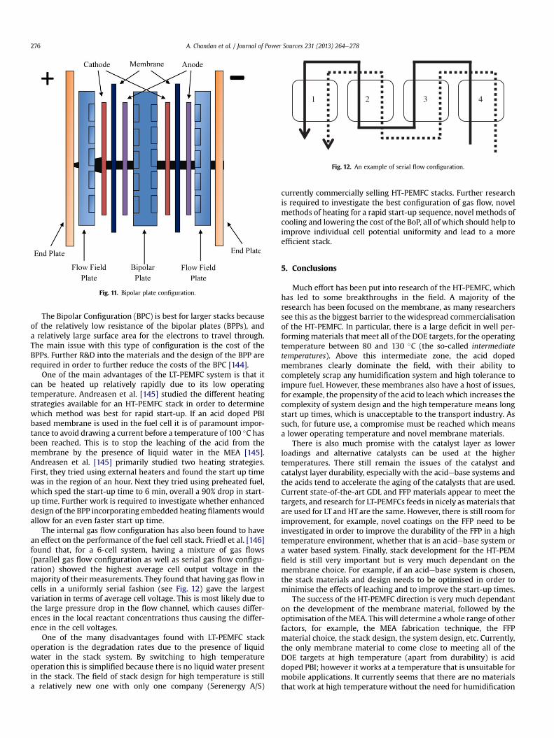
Fig. 11. Bipolar plate configuration.
1 2 3 4
Fig. 12. An example of serial flow configuration.
A. Chandan et al. / Journal of Power Sources 231 (2013) 264e278276
The Bipolar Configuration (BPC) is best for larger stacks becauseof the relatively low resistance of the bipolar plates (BPPs), anda relatively large surface area for the electrons to travel through.The main issue with this type of configuration is the cost of theBPPs. Further R&D into the materials and the design of the BPP arerequired in order to further reduce the costs of the BPC [144].
One of the main advantages of the LT-PEMFC system is that itcan be heated up relatively rapidly due to its low operatingtemperature. Andreasen et al. [145] studied the different heatingstrategies available for an HT-PEMFC stack in order to determinewhich method was best for rapid start-up. If an acid doped PBIbased membrane is used in the fuel cell it is of paramount impor-tance to avoid drawing a current before a temperature of 100 �C hasbeen reached. This is to stop the leaching of the acid from themembrane by the presence of liquid water in the MEA [145].Andreasen et al. [145] primarily studied two heating strategies.First, they tried using external heaters and found the start up timewas in the region of an hour. Next they tried using preheated fuel,which sped the start-up time to 6 min, overall a 90% drop in start-up time. Further work is required to investigate whether enhanceddesign of the BPP incorporating embedded heating filaments wouldallow for an even faster start up time.
The internal gas flow configuration has also been found to havean effect on the performance of the fuel cell stack. Friedl et al. [146]found that, for a 6-cell system, having a mixture of gas flows(parallel gas flow configuration as well as serial gas flow configu-ration) showed the highest average cell output voltage in themajority of their measurements. They found that having gas flow incells in a uniformly serial fashion (see Fig. 12) gave the largestvariation in terms of average cell voltage. This is most likely due tothe large pressure drop in the flow channel, which causes differ-ences in the local reactant concentrations thus causing the differ-ence in the cell voltages.
One of the many disadvantages found with LT-PEMFC stackoperation is the degradation rates due to the presence of liquidwater in the stack system. By switching to high temperatureoperation this is simplified because there is no liquid water presentin the stack. The field of stack design for high temperature is stilla relatively new one with only one company (Serenergy A/S)
currently commercially selling HT-PEMFC stacks. Further researchis required to investigate the best configuration of gas flow, novelmethods of heating for a rapid start-up sequence, novel methods ofcooling and lowering the cost of the BoP, all of which should help toimprove individual cell potential uniformity and lead to a moreefficient stack.
5. Conclusions
Much effort has been put into research of the HT-PEMFC, whichhas led to some breakthroughs in the field. A majority of theresearch has been focused on the membrane, as many researcherssee this as the biggest barrier to the widespread commercialisationof the HT-PEMFC. In particular, there is a large deficit in well per-formingmaterials that meet all of the DOE targets, for the operatingtemperature between 80 and 130 �C (the so-called intermediatetemperatures). Above this intermediate zone, the acid dopedmembranes clearly dominate the field, with their ability tocompletely scrap any humidification system and high tolerance toimpure fuel. However, these membranes also have a host of issues,for example, the propensity of the acid to leach which increases thecomplexity of system design and the high temperature means longstart up times, which is unacceptable to the transport industry. Assuch, for future use, a compromise must be reached which meansa lower operating temperature and novel membrane materials.
There is also much promise with the catalyst layer as lowerloadings and alternative catalysts can be used at the highertemperatures. There still remain the issues of the catalyst andcatalyst layer durability, especially with the acidebase systems andthe acids tend to accelerate the aging of the catalysts that are used.Current state-of-the-art GDL and FFP materials appear to meet thetargets, and research for LT-PEMFCs feeds in nicely as materials thatare used for LT and HT are the same. However, there is still room forimprovement, for example, novel coatings on the FFP need to beinvestigated in order to improve the durability of the FFP in a hightemperature environment, whether that is an acidebase system ora water based system. Finally, stack development for the HT-PEMfield is still very important but is very much dependant on themembrane choice. For example, if an acidebase system is chosen,the stack materials and design needs to be optimised in order tominimise the effects of leaching and to improve the start-up times.
The success of the HT-PEMFC direction is very much dependanton the development of the membrane material, followed by theoptimisation of theMEA. This will determine awhole range of otherfactors, for example, the MEA fabrication technique, the FFPmaterial choice, the stack design, the system design, etc. Currently,the only membrane material to come close to meeting all of theDOE targets at high temperature (apart from durability) is aciddoped PBI; however it works at a temperature that is unsuitable formobile applications. It currently seems that there are no materialsthat work at high temperature without the need for humidification

A. Chandan et al. / Journal of Power Sources 231 (2013) 264e278 277
apart from acid doped PBI or ioniceliquid doped materials. Fortransport applications, it appears that the trend has veered towardsintermediate temperatures with some humidification always beingrequired.
References
[1] C. Wieser, Fuel Cells 4 (2004) 245e250.[2] R. Devanathan, Energy & Environmental Science 1 (2008) 101e119.[3] J. Jagur-Grodizinski, Polymers for Advanced Technologies 18 (2007)
785e799.[4] Y.-G. Chun, C.-S. Kim, D.-H. Peck, D.-R. Shin, Journal of Power Sources 71
(1998) 174e178.[5] A. Therdthianwong, P. Saenwiset, S. Therdthianwong, Fuel 91 (2012)
192e199.[6] B. Millington, S. Du, B.G. Pollet, Journal of Power Sources 196 (2011) 9013e
9017.[7] R. Taccani, N. Zuliani, International Journal of Hydrogen Energy 36 (2011)
10282e10287.[8] J.A. Asensio, E.M. Sanchez, P. Gomez-Romero, Chemical Society Reviews 39
(2010) 3210e3239.[9] X. Glipa, A. Hogarth, in, Johnson Matthey Technology Centre (2001) 1e68.
[10] P. Costamagna, C. Yang, A.B. Bocarsly, S. Srinivasan, Electrochimica Acta 47(2002) 1023e1033.
[11] S. Reichman, A. Ulus, E. Peled, Journal of The Electrochemical Society 154(2007) B327eB333.
[12] M. Rikukawa, K. Sanui, Progress in Polymer Science 25 (2000) 1463e1502.[13] C. Yang, P. Costamagna, S. Srinivasan, J. Benziger, A.B. Bocarsly, Journal of
Power Sources 103 (2001) 1e9.[14] Q. Li, R. He, J.O. Jensen, N.J. Bjerrum, Chemistry of Materials 15 (2003) 4896e
4915.[15] C. Pan, R. He, Q. Li, J.O. Jensen, N.J. Bjerrum, H.A. Hjulmand, A.B. Jensen,
Journal of Power Sources 145 (2005) 392e398.[16] Q. Li, H. Ronghuan, G. Ji-An, J.O. Jensen, N.J. Bjerrum, Journal of the Elec-
trochemical Society 150 (2003) A1599eA1605.[17] M. Martinez, Y. Molmeret, L. Cointeaux, C. Iojoiu, J.-C. Leprêtre, N. El Kissi,
P. Judeinstein, J.-Y. Sanchez, Journal of Power Sources 195 (2010) 5829e5839.
[18] D. Villers, X. Jacques-Bedard, J.P. Dodelet, Journal of the ElectrochemicalSociety 151 (2004) A1507eA1515.
[19] H.-S. Oh, J.-G. Oh, B. Roh, I. Hwang, H. Kim, Development of highly active andstable non-precious oxygen reduction catalysts for PEM fuel cells usingpolypyrrole and a chelating agent, Electrochemistry Communications 13(2011) 879e881.
[20] S. Bose, T. Kuila, T.X.H. Nguyen, N.H. Kim, K.-t. Lau, J.H. Lee, Polymermembranes for high temperature proton exchange membrane fuel cell:Recent advances and challenges, Progress in Polymer Science 36 (2011)813e843.
[21] L. Avery, in, Department for Transport (2009).[22] Y. Wang, K.S. Chen, J. Mishler, S.C. Cho, X.C. Adroher, Applied Energy 88
(2011).[23] J.K. Kallitsis, M. Geormezi, S.G. Neophytides, Polymer International 58 (2009)
1226e1233.[24] K. Miyatake, M. Watanabe, Electrochemistry 73 (2005) 12e19.[25] S.J. Hamrock, M.A. Yandrasits, Polymer Reviews 46 (2006) 219e244.[26] M. Mamlouk, K. Scott, International Journal of Energy Research 35 (2011)
507e519.[27] E.J. Carlson, P. Kopf, J. Sinha, S. Sriramulu, Y. Yang, in, National Renewable
Energy Laboratory, 2005.[28] J. Spendelow, J. Marcinkoski, in, DOE (2009).[29] O.o.E.E.a.R, Energy, U.S. Department of Energy, Washington, 2011.[30] A.-C. Dupuis, Progress in Materials Science 56 (2011) 289e327.[31] H. Bai, W.S.W. Ho, Polymer International 60 (2011) 26e41.[32] S.J. Peighambardoust, S. Rowshanzamir, M. Amjadi, International Journal of
Hydrogen Energy 35 (2010) 9349e9384.[33] N. Gourdoupi, J.K. Kallitsis, S. Neophytides, Journal of Power Sources 195
(2010) 170e174.[34] S.M.J. Zaidi, Research Trends in Polymer Electrolyte Membranes for PEMFC,
Springer Science þ Business Media, 2009.[35] R.H. Puffer, S.J. Rock, Journal of Fuel Cell Science and Technology 6 (2009).[36] K.E. Martin, J.P. Kopasz, Fuel Cells 9 (2009) 356e362.[37] Y. Shao, G. Yin, Z. Wang, Y. Gao, Journal of Power Sources 167 (2007)
235e242.[38] K. Miyatake, M. Watanabe, Journal of Materials Chemistry 16 (2006) 4465e
4467.[39] B. Smitha, S. Sridhar, A.A. Khan, Journal of Membrane Science 259 (2005)
10e26.[40] M.E. Schuster, W.H. Meyer, Annual Review of Materials Research 33 (2003)
233e261.[41] J. Roziere, D.J. Jones, Annual Review of Materials Research 33 (2003) 503e555.[42] V. Mehta, J.S. Cooper, Journal of Power Sources 114 (2003) 32e53.[43] A. Glusen, D. Stolten, Chemie Ingenieur Technik 75 (2003) 1591e1597.[44] J.A. Kerres, Journal of Membrane Science 185 (2001) 3e27.
[45] P. Costamagna, S. Srinivasan, Journal of Power Sources 102 (2001) 242e252.[46] C.H. Park, C.H. Lee, M.D. Guiver, Y.M. Lee, Progress in Polymer Science 36
(2011) 1443e1498.[47] A. El-Kharouf, A. Chandan, M. Hattenberger, B.G. Pollet, Proton exchange
membrane fuel cell degradation and testing: review, Journal of the EnergyInstitute 85 (2012) 188e200.
[48] S.Z. Yi, F.F. Zhang, W. Li, C. Huang, H.N. Zhang, M. Pan, Journal of MembraneScience 366 (2011) 349e355.
[49] W.H.J. Hogarth, J.C. Diniz da Costa, G.Q. Lu, Journal of Power Sources 142(2005) 223e237.
[50] Y.L. Ma, J.S. Wainright, M.H. Litt, R.F. Savinell, Journal of The ElectrochemicalSociety 151 (2004) A8eA16.
[51] M.K. Mistry, S. Subianto, N.R. Choudhury, N.K. Dutta, Langmuir 25 (2009)9240e9251.
[52] R. Souzy, B. Ameduri, Progress in Polymer Science 30 (2005) 644e687.[53] A. Stassi, I. Gatto, E. Passalacqua, V. Antonucci, A.S. Arico, L. Merlo, C. Oldani,
E. Pagano, Journal of Power Sources 196 (2011) 8925e8930.[54] A.S. Arico, A. Stassi, E. Modica, R. Ornelas, I. Gatto, E. Passalacqua,
V. Antonucci, Journal of Power Sources 178 (2008) 525e536.[55] Z. Tu, H. Zhang, Z. Luo, J. Liu, Z. Wan, M. Pan, Journal of Power Sources 222
(2013) 277e281.[56] K.D. Kreuer, M. Schuster, B. Obliers, O. Diat, U. Traub, A. Fuchs, U. Klock,
S.J. Paddison, J. Maier, Journal of Power Sources 178 (2008) 499e509.[57] C. Wannek, W. Lehnert, J. Mergel, Journal of Power Sources 192 (2009)
258e266.[58] Q. Li, J.O. Jensen, R.F. Savinell, N.J. Bjerrum, Progress in Polymer Science 34
(2009) 449e477.[59] H.L. Lin, Y.C. Chou, T.L. Yu, S.W. Lai, International Journal of Hydrogen Energy
37 (2012) 383e392.[60] S. Wang, G. Zhang, M. Han, H. Li, Y. Zhang, J. Ni, W. Ma, M. Li, J. Wang, Z. Liu,
L. Zhang, H. Na, International Journal of Hydrogen Energy 36 (2011) 8412e8421.
[61] M.M. Han, G. Zhang, Z.G. Liu, S.A. Wang, M.Y. Li, J. Zhu, H.T. Li, Y. Zhang,C.M. Lew, H. Na, Journal of Materials Chemistry 21 (2011) 2187e2193.
[62] S.K. Kim, S.W. Choi, W.S. Jeon, J.O. Park, T. Ko, H. Chang, J.C. Lee, Macro-molecules 45 (2012) 1438e1446.
[63] D. Aili, Q.F. Li, E. Christensen, J.O. Jensen, N.J. Bjerrum, Polymer International60 (2011) 1201e1207.
[64] L. Sheng, H.J. Xu, X.X. Guo, J.H. Fang, L.A. Fang, J. Yin, Journal of Power Sources196 (2011) 3039e3047.
[65] J.A. Mader, B.C. Benicewicz, Fuel Cells 11 (2011) 222e237.[66] J.A. Mader, B.C. Benicewicz, Macromolecules 43 (2010) 6706e6715.[67] R.L. Thankamony, J.M. Hwang, T.H. Kim, Journal of Membrane Science 392
(2012) 58e65.[68] K. Miyatake, T. Yasuda, M. Watanabe, Journal of Polymer Science Part A-
Polymer Chemistry 46 (2008) 4469e4478.[69] Y. Devrim, S. Erkan, N. Bac, I. Eroglu, International Journal of Hydrogen
Energy 34 (2009) 3467e3475.[70] C. Iojoiu, J.Y. Sanchez, High Performance Polymers 21 (2009) 673e692.[71] B.P. Tripathi, V.K. Shahi, Organic–inorganic nanocomposite polymer elec-
trolyte membranes for fuel cell applications, Progress in Polymer Science 36(2011) 945e979.
[72] C. Laberty-Robert, K. Valle, F. Pereira, C. Sanchez, Chemical Society Reviews40 (2011) 961e1005.
[73] S.M.Haile, D.A. Boysen, C.R.I. Chisholm, R.B.Merle, Nature 410 (2001) 910e913.[74] J.H. Piao, S.J. Liao, Z.X. Liang, Journal of Power Sources 193 (2009) 483e487.[75] E.M. Tsui, M.M. Cortalezzi, M.R. Wiesner, Journal of Membrane Science 306
(2007) 8e15.[76] S. Kaliaguine, S.D. Mikhailenko, K.P. Wang, P. Xing, G. Robertson, M. Guiver,
Catalysis Today 82 (2003) 213e222.[77] C. Wannek, I. Konradi, J. Mergel, W. Lehnert, International Journal of
Hydrogen Energy 34 (2009) 9479e9485.[78] A. Verma, K. Scott, Journal of Solid State Electrochemistry 14 (2010) 213e219.[79] H. Zarrin, D. Higgins, Y. Jun, Z. Chen, M. Fowler, The Journal of Physical
Chemistry C 115 (2011) 20774e20781.[80] B. Bae, T. Yoda, K. Miyatake, M. Uchida, H. Uchida, M. Watanabe, Journal of
Physical Chemistry B 114 (2010) 10481e10487.[81] U.S.D.o, Energy, US DOE, 2010.[82] D. Larminie, in.[83] B. Avasarala, R. Moore, P. Haldar, Electrochimica Acta 55 (2010) 4765e4771.[84] P.J. Ferreira, G.J. la O, Y. Shao-Horn, D. Morgan, R. Makharia, S. Kocha,
H.A. Gasteiger, Journal of the Electrochemical Society 152 (2005) A2256eA2271.
[85] H. Yuan, H. Song, X. Qiu, W. Zhu, L. Chen, Electrochemistry Communications12 (2010) 14e17.
[86] O.J. Curnick, P.M. Mendes, B.G. Pollet, Electrochemistry Communications 12(2010) 1017e1020.
[87] C. lamy, D.J. Jones, C. Coutanceau, P. Brault, S. Martemianov, Y. Bultel, Elec-trochimica Acta, 2010.
[88] P.C. Jennings, B.G. Pollet, R.L. Johnston, Physical Chemistry Chemical Physics,2012.
[89] Q. Zeng, L. Zheng, J. Zeng, S. Liao, Journal of Power Sources 205 (2012)201e206.
[90] J. Parrondo, F. Mijangos, B. Rambabu, Journal of Power Sources 195 (2010)3977e3983.
A. Chandan et al. / Journal of Power Sources 231 (2013) 264e278278
[91] A. El-kharouf, B.G. Pollet, Chapter 4-gas diffusion media and their degrada-tion, in: Polymer Electrolyte Fuel Cell Degradation, Academic Press, Boston,2012, pp. 215e247.
[92] J. Lobato, P. Cañizares, M.A. Rodrigo, C. Ruiz-López, J.J. Linares, Journal ofApplied Electrochemistry 38 (2008) 793e802.
[93] P.J. Hamilton, B.G. Pollet, Fuel Cells 10 (2010) 489e509.[94] J. Lobato, P. Cañizares, M.A. Rodrigo, J.J. Linares, F.J. Pinar, International
Journal of Hydrogen Energy 35 (2010) 1347e1355.[95] T. Sousa, M. Mamlouk, K. Scott, C.M. Rangel, Fuel Cells 12 (2012) 566e576.[96] C. Pan, Q. Li, J.O. Jensen, R. He, L.N. Cleemann, M.S. Nilsson, N.J. Bjerrum,
Q. Zeng, Journal of Power Sources 172 (2007) 278e286.[97] J. Hu, H. Zhang, Y. Zhai, G. Liu, J. Hu, B. Yi, Electrochimica Acta 52 (2006)
394e401.[98] P. Krishnan, J.-S. Park, C.-S. Kim, Journal of Power Sources 159 (2006) 817e823.[99] Y. Song, Y. Wei, H. Xu, M. Williams, Y. Liu, L.J. Bonville, H. Russell Kunz,
J.M. Fenton, Journal of Power Sources 141 (2005) 250e257.[100] F. Seland, T. Berning, B. Børresen, R. Tunold, Journal of Power Sources 160
(2006) 27e36.[101] J. Lobato, P. Canizares, M.A. Rodrigo, J.J. Linares, J.A. Aguilar, Journal of
Membrane Science 306 (2007) 47e55.[102] S.-Y. Lee, T. Yasuda, M. Watanabe, Journal of Power Sources 195 (2010)
5909e5914.[103] J. Zhang, Z. Xie, J. Zhang, Y. Tang, C. Song, T. Navessin, Z. Shi, D. Song,
H. Wang, D.P. Wilkinson, Z.-S. Liu, S. Holdcroft, Journal of Power Sources 160(2006) 872e891.
[104] Y. Zhai, H. Zhang, D. Xing, Z.-G. Shao, Journal of Power Sources 164 (2007)126e133.
[105] C. Hartnig, T.J. Schmidt, Electrochimica Acta 56 (2011) 4237e4242.[106] S. Sharma, B.G. Pollet, Journal of Power Sources 208 (2012) 96e119.[107] E.A. Ticianelli, C.R. Derouin, S. Srinivasan, Journal of Electroanalytical
Chemistry and Interfacial Electrochemistry 251 (1988) 275e295.[108] H.A. Gasteiger, J.E. Panels, S.G. Yan, Journal of Power Sources 127 (2004)
162e171.[109] Q. Li, J.O. Jensen, C. Pan, V. Bandur, M.S. Nilsson, F. Schonberger, A. Chromik,
M. Hein, T. Haring, J. Kerres, N.J. Bjerrum, Fuel Cells 8 (2008) 188e199.[110] E. Novillo, M. Pardo, A. Garcia-Luis, Journal of Fuel Cell Science and Tech-
nology 8 (2011).[111] L.J. Bonville, H.R. Kunz, Y. Song, A. Mientek, M. Williams, A. Ching,
J.M. Fenton, Journal of Power Sources 144 (2005) 107e112.[112] H.-J. Lee, B.G. Kim, D.H. Lee, S.J. Park, Y. Kim, J.W. Lee, D. Henkensmeier,
S.W. Nam, H.-J. Kim, H. Kim, J.-Y. Kim, International Journal of HydrogenEnergy 36 (2011) 5521e5526.
[113] D.J.L. Brett, A.R. Kucernak, P. Aguiar, S.. Atkins, N.P. Brandon, R. Clague,L.F. Cohen, G. Hinds, C. Kalyvas, G.J. Offer, B. Ladewig, R. Maher, A. Marquis,P. Shearing, N. Vasileiadis, V. Vesovic, ChemPhysChem 11 (2010) 2714e2731.
[114] J.O. Jensen, Q. Li, C. Pan, N.J. Bjerrum, H.C. Rudbeck, T. Steenberg, in: 18thWorld Hydrogen Energy Conference, 2010.
[115] S. Zhang, X. Yuan, H. Wang, W. Mérida, H. Zhu, J. Shen, S. Wu, J. Zhang,International Journal of Hydrogen Energy 34 (2009) 388e404.
[116] W. Schmittinger, A. Vahidi, Journal of Power Sources 180 (2008) 1e14.[117] P. Rama, R. Chen, J. Andrews, Proceedings of the Institution of Mechanical
Engineers, Part A: Journal of Power and Energy 222 (2008) 421e441.[118] J. Wu, X.Z. Yuan, J.J. Martin, H. Wang, J. Zhang, J. Shen, S. Wu, W. Merida,
Journal of Power Sources 184 (2008) 104e119.[119] Y. Zhai, H. Zhang, G. Liu, J. Hu, B. Yi, Journal of The Electrochemical Society
154 (2007) B72eB76.[120] G. Liu, H. Zhang, J. Hu, Y. Zhai, D. Xu, Z.-g . Shao, Journal of Power Sources 162
(2006) 547e552.[121] S. Yu, L. Xiao, B.C. Benicewicz, Fuel Cells 8 (2008) 165e174.[122] C. Wannek, B. Kohnen, H.F. Oetjen, H. Lippert, J. Mergel, Fuel Cells 8 (2008)
87e95.[123] P. Moçotéguy, B. Ludwig, J. Scholta, Y. Nedellec, D.J. Jones, J. Rozière, Fuel
Cells 10 (2010) 299e311.[124] H.L. Lin, Y.S. Hsieh, C.W. Chiu, T.L. Yu, L.C. Chen, Journal of Power Sources 193
(2009) 170e174.[125] X. Cheng, J. Zhang, Y. Tang, C. Song, J. Shen, D. Song, J. Zhang, Journal of
Power Sources 167 (2007) 25e31.[126] C. Bonnet, S. Didierjean, N. Guillet, S. Besse, T. Colinart, P. Carré, Journal of
Power Sources 182 (2008) 441e448.[127] D. Chu, R. Jiang, Journal of Power Sources 80 (1999) 226e234.[128] K.S. Dhathathreyan, P. Sridhar, G. Sasikumar, K.K. Ghosh, G. Velayutham,
N. Rajalakshmi, C.K. Subramaniam, M. Raja, K. Ramya, International Journalof Hydrogen Energy 24 (1999) 1107e1115.
[129] S. Pandiyan, K. Jayakumar, N. Rajalakshmi, K.S. Dhathathreyan, InternationalJournal of Heat and Mass Transfer 51 (2008) 469e473.
[130] P. Rodatz, F. Büchi, C. Onder, L. Guzzella, Journal of Power Sources 128 (2004)208e217.
[131] R. Eckl, W. Zehtner, C. Leu, U. Wagner, Journal of Power Sources 138 (2004)137e144.
[132] M. Miller, A. Bazylak, Journal of Power Sources 196 (2011) 601e613.[133] F. Urbani, O. Barbera, G. Giacoppo, G. Squadrito, E. Passalacqua, International
Journal of Hydrogen Energy 33 (2008) 3137e3141.[134] J.I. San Martin, I. Zamora, J.J. San Martin, V. Aperribay, E. Torres, P. Eguia,
Energy 35 (2010) 1898e1907.
[135] S. Giddey, F.T. Ciacchi, S.P.S. Badwal, Journal of Power Sources 125 (2004)155e165.
[136] C. Tori, M. Baleztena, C. Peralta, R. Calzada, E. Jorge, D. Barsellini,G. Garaventta, A. Visintin, W.E. Triaca, International Journal of HydrogenEnergy 33 (2008) 3588e3591.
[137] A.J. del Real, A. Arce, C. Bordons, Journal of Power Sources 173 (2007) 310e324.[138] A. Heinzel, F. Mahlendorf, O. Niemzig, C. Kreuz, Journal of Power Sources 131
(2004) 35e40.[139] O.J. Murphy, A. Cisar, E. Clarke, Electrochimica Acta 43 (1998) 3829e3840.[140] J. Hamelin, K. Agbossou, A. Laperrière, F. Laurencelle, T.K. Bose, International
Journal of Hydrogen Energy 26 (2001) 625e629.[141] J. Clement, X. Wang, Applied Thermal Engineering 50 (2013) 268e274.[142] J. Scholta, M. Messerschmidt, L. Jörissen, C. Hartnig, Journal of Power Sources
190 (2009) 83e85.[143] A. Bazylak, International Journal of Hydrogen Energy 34 (2009) 3845e3857.[144] X.G. Li, M. Sabir, International Journal of Hydrogen Energy 30 (2005)
359e371.[145] S.J. Andreasen, S.K. Kær, International Journal of Hydrogen Energy 33 (2008)
4655e4664.[146] A. Friedl, S.D. Fraser, W.R. Baumgartner, V. Hacker, Journal of Power Sources
185 (2008) 248e260.[147] S. Banerjee, D.E. Curtin, Journal of Fluorine Chemistry 125 (2004) 1211e
1216.[148] C. Iojoiu, F. Chabert, M. Maréchal, N.E. Kissi, J. Guindet, J.Y. Sanchez, Journal of
Power Sources 153 (2006) 198e209.[149] K. Miyatake, B. Bae, M. Watanabe, Polymer Chemistry, 2011, UK.[150] J. Parvole, P. Jannasch, Macromolecules 41 (2008) 3893e3903.[151] G.B. Ye, K. Li, C.A. Xiao, W. Chen, H.N. Zhang, M. Pan, Journal of Applied
Polymer Science 120 (2011) 1186e1192.[152] Z.B.Wang,H.L. Tang,M. Pan, Journal ofMembraneScience 369 (2011) 250e257.[153] D.M. Xing, G.H. He, Z.J. Hou, P.W. Ming, S.F. Song, International Journal of
Hydrogen Energy 36 (2011) 2177e2183.[154] T. Sancho, J. Soler, M.P. Pina, Journal of Power Sources 169 (2007) 92e97.[155] M. Amirinejad, S.S. Madaeni, E. Rafiee, S. Amirinejad, Cesium hydrogen salt of
heteropolyacids/Nafion nanocomposite membranes for proton exchangemembrane fuel cells, Journal of Membrane Science 377 (2011) 89e98.
[156] D.X. Luu, D. Kim, Journal of Membrane Science 371 (2011) 248e253.[157] Y. Kozawa, S. Suzuki, M. Miyayama, T. Okumiya, E. Traversa, Solid State Ionics
181 (2010) 348e353.[158] H. Pu, D. Wang, Z. Yang, Journal of Membrane Science 360 (2010) 123e129.[159] M.-S. Jun, Y.-W. Choi, J.-D. Kim, Journal of Membrane Science.[160] J. Peron, A. Mani, X.S. Zhao, D. Edwards, M. Adachi, T. Soboleva, Z.Q. Shi,
Z. Xie, T. Navessin, S. Holdcroft, Journal of Membrane Science 356 (2010)44e51.
[161] W. Liu, S.J. Wang, M. Xiao, D.M. Han, Y.Z. Meng, Chemical Communications48 (2012) 3415e3417.
[162] M.M. Nasef, H. Saidi, K.M. Dahlan, Polymer International 60 (2011) 186e193.[163] L. Maldonado, J.C. Perrin, J. Dillet, O. Lottin, Journal of Membrane Science 389
(2012) 43e56.[164] H. Namazi, H. Ahmadi, Journal of Power Sources 196 (2011) 2573e2583.[165] C. Liang, C. Nagami, T. Maruyama, T. Sotani, H. Matsuyama, Journal of Applied
Polymer Science 109 (2008) 3739e3745.[166] S.E. Nam, S.O. Kim, Y. Kang, J.W. Lee, K.H. Lee, Journal of Membrane Science
322 (2008) 466e474.[167] J.J. Yuan, H.T. Pu, Z.L. Yang, Journal of Polymer Science Part A-Polymer
Chemistry 47 (2009) 2647e2655.[168] H. Zarrin, Y. Jun, M. Fowler, Z. Chen, Abstract #643, 219th ECS Meeting, �
2011, The Electrochemical Society, 2011.[169] M. Casciola, D. Capitani, A. Comite, A. Donnadio, V. Frittella, M. Pica,
M. Sganappa, A. Varzi, Fuel Cells 8 (2008) 217e224.[170] Y.T. Kim, K.H. Kim, M.K. Song, H.W. Rhee, Current Applied Physics 6 (2006)
612e615.[171] E. Fontananova, F. Trotta, J.C. Jansen, E. Drioli, Journal of Membrane Science
348 (2010) 326e336.[172] G. Frutsaert, G. David, B. Ameduri, D.J. Jones, J. Roziere, X. Glipa, Journal of
Membrane Science 367 (2011) 127e133.[173] X.H. Ye, H. Bai, W.S.W. Ho, Journal of Membrane Science 279 (2006)
570e577.[174] K. Miyatake, T. Yasuda, M. Hirai, M. Nanasawa, M. Watanabe, Journal of
Polymer Science Part A-Polymer Chemistry 45 (2007) 157e163.[175] B. Bae, T. Yoda, K. Miyatake, H. Uchida, M. Watanabe, Angewandte Chemie-
international Edition 49 (2010) 317e320.[176] Q.F. Li, H.C. Rudbeck, A. Chromik, J.O. Jensen, C. Pan, T. Steenberg,
M. Calverley, N.J. Bjerrum, J. Kerres, Journal of Membrane Science 347 (2010)260e270.
[177] H.S. Lee, A. Roy, O. Lane, J.E. McGrath, Polymer 49 (2008) 5387e5396.[178] G. Lakshminarayana, M. Nogami, I.V. Kityk, Energy 35 (2010) 5260e5268.[179] G. Lakshminarayana, R. Vijayaraghavan, M. Nogami, I.V. Kityk, Journal of The
Electrochemical Society 158 (2011) B376eB383.[180] G. Lakshminarayana, M. Nogami, I.V. Kityk, Journal of Alloys and Compounds
509 (2011) 2238e2242.[181] N.N.Krishnan,H.-J. Lee,H.-J. Kim, J.-Y. Kim, I.Hwang, J.H. Jang, E.A.Cho, S.-K. Kim,
D. Henkensmeier, S.-A. Hong, T.-H. Lim, European Polymer Journal 46 (2010)1633e1641.