Lensfree Fluorescent On-Chip Imaging of Transgenic Caenorhabditis elegans Over an Ultra-Wide...
9
Lensfree Fluorescent On-Chip Imaging of Transgenic Caenorhabditis elegans Over an Ultra-Wide Field-of-View Ahmet F. Coskun 1. , Ikbal Sencan 1. , Ting-Wei Su 1. , Aydogan Ozcan 1,2 * 1 Electrical Engineering Department, University of California Los Angeles, Los Angeles, California, United States of America, 2 California NanoSystems Institute (CNSI), Los Angeles, California, United States of America Abstract We demonstrate lensfree on-chip fluorescent imaging of transgenic Caenorhabditis elegans (C. elegans) over an ultra-wide field-of-view (FOV) of e.g., .2–8 cm 2 with a spatial resolution of ,10mm. This is the first time that a lensfree on-chip platform has successfully imaged fluorescent C. elegans samples. In our wide-field lensfree imaging platform, the transgenic samples are excited using a prism interface from the side, where the pump light is rejected through total internal reflection occurring at the bottom facet of the substrate. The emitted fluorescent signal from C. elegans samples is then recorded on a large area opto-electronic sensor-array over an FOV of e.g., .2–8 cm 2 , without the use of any lenses, thin-film interference filters or mechanical scanners. Because fluorescent emission rapidly diverges, such lensfree fluorescent images recorded on a chip look blurred due to broad point-spread-function of our platform. To combat this resolution challenge, we use a compressive sampling algorithm to uniquely decode the recorded lensfree fluorescent patterns into higher resolution images, demonstrating ,10 mm resolution. We tested the efficacy of this compressive decoding approach with different types of opto-electronic sensors to achieve a similar resolution level, independent of the imaging chip. We further demonstrate that this wide FOV lensfree fluorescent imaging platform can also perform sequential bright-field imaging of the same samples using partially-coherent lensfree digital in-line holography that is coupled from the top facet of the same prism used in fluorescent excitation. This unique combination permits ultra-wide field dual-mode imaging of C. elegans on a chip which could especially provide a useful tool for high-throughput screening applications in biomedical research. Citation: Coskun AF, Sencan I, Su T-W, Ozcan A (2011) Lensfree Fluorescent On-Chip Imaging of Transgenic Caenorhabditis elegans Over an Ultra-Wide Field-of- View. PLoS ONE 6(1): e15955. doi:10.1371/journal.pone.0015955 Editor: Eleftherios Mylonakis, Massachusetts General Hospital, United States of America Received September 30, 2010; Accepted November 30, 2010; Published January 6, 2011 Copyright: ß 2011 Coskun et al. This is an open-access article distributed under the terms of the Creative Commons Attribution License, which permits unrestricted use, distribution, and reproduction in any medium, provided the original author and source are credited. Funding: A. Ozcan gratefully acknowledges the support of NSF (CAREER Award on BioPhotonics), the Office of Naval Research (ONR) under the Young Investigator Award 2009 and the NIH Director’s New Innovator Award - Award Number DP2OD006427 from the Office of the Director, National Institutes of Health. The authors also acknowledge the support of the Okawa Foundation, Vodafone Americas Foundation, DARPA DSO (under 56556-MS-DRP), NSF BISH program (under Awards # 0754880 and 0930501), NIH (under 1R21EB009222-01), and AFOSR (under Project #08NE255). The funders had no role in study design, data collection and analysis, decision to publish, or preparation of the manuscript. Competing Interests: The authors have declared that no competing interests exist. * E-mail: [email protected] . These authors contributed equally to this work. Introduction C. elegans is an important model organism that has been widely studied in various fields such as genetics [1], oncology [2] and neurobiology [3]. Wide-field optical imaging of C. elegans is an essential need for all these fields to enable high-throughput screening of this model organism. While several high-throughput imaging platforms have been successfully demonstrated so far [4–13], the main stream for this application involves the use of lens-based conventional optical microscopes which can only provide a limited field-of-view (FOV) of e.g., #1mm 2 , and therefore require mechanical scanning to provide a larger imaging FOV. In addition to this, such conventional optical microscopy platforms are rather bulky, and do not provide a decent match in terms of compactness to micro-fluidic technologies that are becoming widely used today in high-throughput screening of C. elegans. To provide an alternative solution to this imaging need, here we demonstrate ultra-wide field fluorescent imaging of transgenic C. elegans over an FOV of .2–8 cm 2 with a spatial resolution of ,10 mm. This platform relies on lensfree on-chip imaging which, broadly defined, is becoming an important substitute for conven- tional microscopes especially for high-throughput imaging applica- tions [14–21]. In our on-chip fluorescent imaging platform (see Fig. 1), transgenic C. elegans samples are excited through a prism interface where the excitation light is rejected based on total internal reflection (TIR) that is occurring at the bottom facet of the glass substrate. The emitted fluorescent signal from the body of the worm does not entirely obey TIR and therefore can be detected by a wide- field opto-electronic sensor-array e.g., a charge-coupled-device (CCD) without the use of any lenses. This detection process occurs through a wide angular range (corresponding to numerical aperture of ,1.0) and because the fluorescent emission from the sample is not directional, the point-spread-function of such a lensfree fluorescent imaging platform will be rather broad, which will significantly limit the achievable raw spatial resolution. To combat this problem we have recently demonstrated the use of a deconvolution approach (namely the Lucy-Richardson algorithm [22–24]) to achieve ,40– 50mm resolution in lensfree fluorescent imaging of e.g., labeled white blood cells [14]. While this is still a useful resolution level for on-chip detection and counting of e.g., rare cells, a significant performance improvement would be needed to lensfree image C elegans samples with much better resolution. PLoS ONE | www.plosone.org 1 January 2011 | Volume 6 | Issue 1 | e15955
Transcript of Lensfree Fluorescent On-Chip Imaging of Transgenic Caenorhabditis elegans Over an Ultra-Wide...
Lensfree Fluorescent On-Chip Imaging of TransgenicCaenorhabditis elegans Over an Ultra-Wide Field-of-ViewAhmet F. Coskun1., Ikbal Sencan1., Ting-Wei Su1., Aydogan Ozcan1,2*
1 Electrical Engineering Department, University of California Los Angeles, Los Angeles, California, United States of America, 2 California NanoSystems Institute (CNSI), Los
Angeles, California, United States of America
Abstract
We demonstrate lensfree on-chip fluorescent imaging of transgenic Caenorhabditis elegans (C. elegans) over an ultra-widefield-of-view (FOV) of e.g., .2–8 cm2 with a spatial resolution of ,10mm. This is the first time that a lensfree on-chipplatform has successfully imaged fluorescent C. elegans samples. In our wide-field lensfree imaging platform, the transgenicsamples are excited using a prism interface from the side, where the pump light is rejected through total internal reflectionoccurring at the bottom facet of the substrate. The emitted fluorescent signal from C. elegans samples is then recorded on alarge area opto-electronic sensor-array over an FOV of e.g., .2–8 cm2, without the use of any lenses, thin-film interferencefilters or mechanical scanners. Because fluorescent emission rapidly diverges, such lensfree fluorescent images recorded ona chip look blurred due to broad point-spread-function of our platform. To combat this resolution challenge, we use acompressive sampling algorithm to uniquely decode the recorded lensfree fluorescent patterns into higher resolutionimages, demonstrating ,10 mm resolution. We tested the efficacy of this compressive decoding approach with differenttypes of opto-electronic sensors to achieve a similar resolution level, independent of the imaging chip. We furtherdemonstrate that this wide FOV lensfree fluorescent imaging platform can also perform sequential bright-field imaging ofthe same samples using partially-coherent lensfree digital in-line holography that is coupled from the top facet of the sameprism used in fluorescent excitation. This unique combination permits ultra-wide field dual-mode imaging of C. elegans on achip which could especially provide a useful tool for high-throughput screening applications in biomedical research.
Citation: Coskun AF, Sencan I, Su T-W, Ozcan A (2011) Lensfree Fluorescent On-Chip Imaging of Transgenic Caenorhabditis elegans Over an Ultra-Wide Field-of-View. PLoS ONE 6(1): e15955. doi:10.1371/journal.pone.0015955
Editor: Eleftherios Mylonakis, Massachusetts General Hospital, United States of America
Received September 30, 2010; Accepted November 30, 2010; Published January 6, 2011
Copyright: � 2011 Coskun et al. This is an open-access article distributed under the terms of the Creative Commons Attribution License, which permitsunrestricted use, distribution, and reproduction in any medium, provided the original author and source are credited.
Funding: A. Ozcan gratefully acknowledges the support of NSF (CAREER Award on BioPhotonics), the Office of Naval Research (ONR) under the YoungInvestigator Award 2009 and the NIH Director’s New Innovator Award - Award Number DP2OD006427 from the Office of the Director, National Institutes ofHealth. The authors also acknowledge the support of the Okawa Foundation, Vodafone Americas Foundation, DARPA DSO (under 56556-MS-DRP), NSF BISHprogram (under Awards # 0754880 and 0930501), NIH (under 1R21EB009222-01), and AFOSR (under Project #08NE255). The funders had no role in study design,data collection and analysis, decision to publish, or preparation of the manuscript.
Competing Interests: The authors have declared that no competing interests exist.
* E-mail: [email protected]
. These authors contributed equally to this work.
Introduction
C. elegans is an important model organism that has been widely
studied in various fields such as genetics [1], oncology [2] and
neurobiology [3]. Wide-field optical imaging of C. elegans is an
essential need for all these fields to enable high-throughput
screening of this model organism. While several high-throughput
imaging platforms have been successfully demonstrated so far
[4–13], the main stream for this application involves the use of
lens-based conventional optical microscopes which can only provide
a limited field-of-view (FOV) of e.g., #1mm2, and therefore require
mechanical scanning to provide a larger imaging FOV. In addition
to this, such conventional optical microscopy platforms are rather
bulky, and do not provide a decent match in terms of compactness
to micro-fluidic technologies that are becoming widely used today in
high-throughput screening of C. elegans.
To provide an alternative solution to this imaging need, here we
demonstrate ultra-wide field fluorescent imaging of transgenic C.
elegans over an FOV of .2–8 cm2 with a spatial resolution of
,10 mm. This platform relies on lensfree on-chip imaging which,
broadly defined, is becoming an important substitute for conven-
tional microscopes especially for high-throughput imaging applica-
tions [14–21]. In our on-chip fluorescent imaging platform (see
Fig. 1), transgenic C. elegans samples are excited through a prism
interface where the excitation light is rejected based on total internal
reflection (TIR) that is occurring at the bottom facet of the glass
substrate. The emitted fluorescent signal from the body of the worm
does not entirely obey TIR and therefore can be detected by a wide-
field opto-electronic sensor-array e.g., a charge-coupled-device
(CCD) without the use of any lenses. This detection process occurs
through a wide angular range (corresponding to numerical aperture
of ,1.0) and because the fluorescent emission from the sample is not
directional, the point-spread-function of such a lensfree fluorescent
imaging platform will be rather broad, which will significantly limit
the achievable raw spatial resolution. To combat this problem we
have recently demonstrated the use of a deconvolution approach
(namely the Lucy-Richardson algorithm [22–24]) to achieve ,40–
50mm resolution in lensfree fluorescent imaging of e.g., labeled
white blood cells [14]. While this is still a useful resolution level for
on-chip detection and counting of e.g., rare cells, a significant
performance improvement would be needed to lensfree image C
elegans samples with much better resolution.
PLoS ONE | www.plosone.org 1 January 2011 | Volume 6 | Issue 1 | e15955
For this end, in this manuscript we demonstrate the use of a
more appropriate reconstruction algorithm for lensfree on-chip
imaging of transgenic C. elegans samples to achieve a significantly
improved resolution of ,10 mm over a wide FOV. This approach
is based on compressive sampling theory [25–27], which aims to
recover a sparse function from much fewer samples than it would
be required according to Shannon’s sampling theorem. Trans-
genic C. elegans samples by definition satisfy the sparsity constraint
of compressive sampling, and therefore can be efficiently decoded
by using various compressive decoders that have been developed
recently [28–30]. Our results constitute the first time that alensfree on-chip platform has successfully imaged fluo-rescent C. elegans samples.
In addition to wide-field fluorescent imaging, we also demon-
strate that the same lensfree on-chip platform can also conduct
bright-field transmission imaging of C. elegans samples using
partially coherent digital in-line holography [18,19], which is
coupled to the same platform through the top facet of the prism as
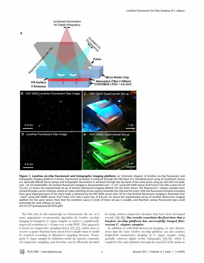
Figure 1. Lensfree on-chip fluorescent and holographic imaging platform. (a) Schematic diagram of lensfree on-chip fluorescent andholographic imaging platform is shown. Fluorescent excitation is achieved through the side facet of a rhomboid prism using an incoherent source(i.e. spectrally filtered Xenon lamp); and holographic illumination is achieved through the top facet of the same prism using an LED (632 nm peak,and ,20 nm bandwidth). (b) Lensfree fluorescent imaging is demonstrated over .2 cm2 using KAF-8300 sensor (Full Frame CCD with a pixel size of5.4 mm). (c) shows the experimental set-up of lensfree fluorescent imaging platform for the same sensor. The fluorescent C. elegans samples wereexcited through a prism interface, where an index matching oil was used to assemble the chip and the prism. Only the fluorescent emission emergingfrom gene-expressed parts of the worm body is detected by the KAF-8300 sensor-chip. (d) On-chip lensfree fluorescent imaging is illustrated over.8cm2 using KAF-39000 sensor (Full Frame CCD with a pixel size of 6.8 mm). (e) shows the experimental set-up of lensfree fluorescent imagingplatform for the same sensor. Note that the excitation source in both of these set-ups is tunable, and therefore various fluorescent dyes couldpotentially be used without an issue.doi:10.1371/journal.pone.0015955.g001
Lensfree Fluorescent On-Chip Imaging of C. elegans
PLoS ONE | www.plosone.org 2 January 2011 | Volume 6 | Issue 1 | e15955
illustrated in Fig. 1. We believe that such ultra-wide field dual-
mode imaging of C. elegans on a chip might provide a useful high-
throughput tool for biomedical research in various fields including
genetics, oncology and neurobiology.
Results and Discussion
Initially, to test the performance of our lensfree on-chip imaging
platform, we imaged fluorescent micro-beads (4 mm diameter,
Excitation: 505nm, Emission: 515nm) by using two different
sensor chips as illustrated in Fig. 1. In specific, we worked with two
full-frame CCD chips namely, KODAK KAF-8300 (5.4 mm pixel
size, ,2.4 cm2 active imaging area) and KODAK KAF-39000
(6.8 mm pixel size, ,18 cm2 active imaging area). In our lensfree
fluorescent imaging modality, because the fluorescent detection
occurs at extremely oblique angles on the sensor chip, depending
on the opto-electronic design of the pixels and the underlying
circuitry of a given chip, the fluorescent point-spread function
(PSF) of our platform would exhibit a noticeable variance in its 2D
pattern from one sensor-chip to another, which requires
calibration of each chip by measuring its unique PSF. Therefore
the main purpose of using different sensor chips in this work was to
demonstrate sensor independent performance of our lensfree
imaging modality.
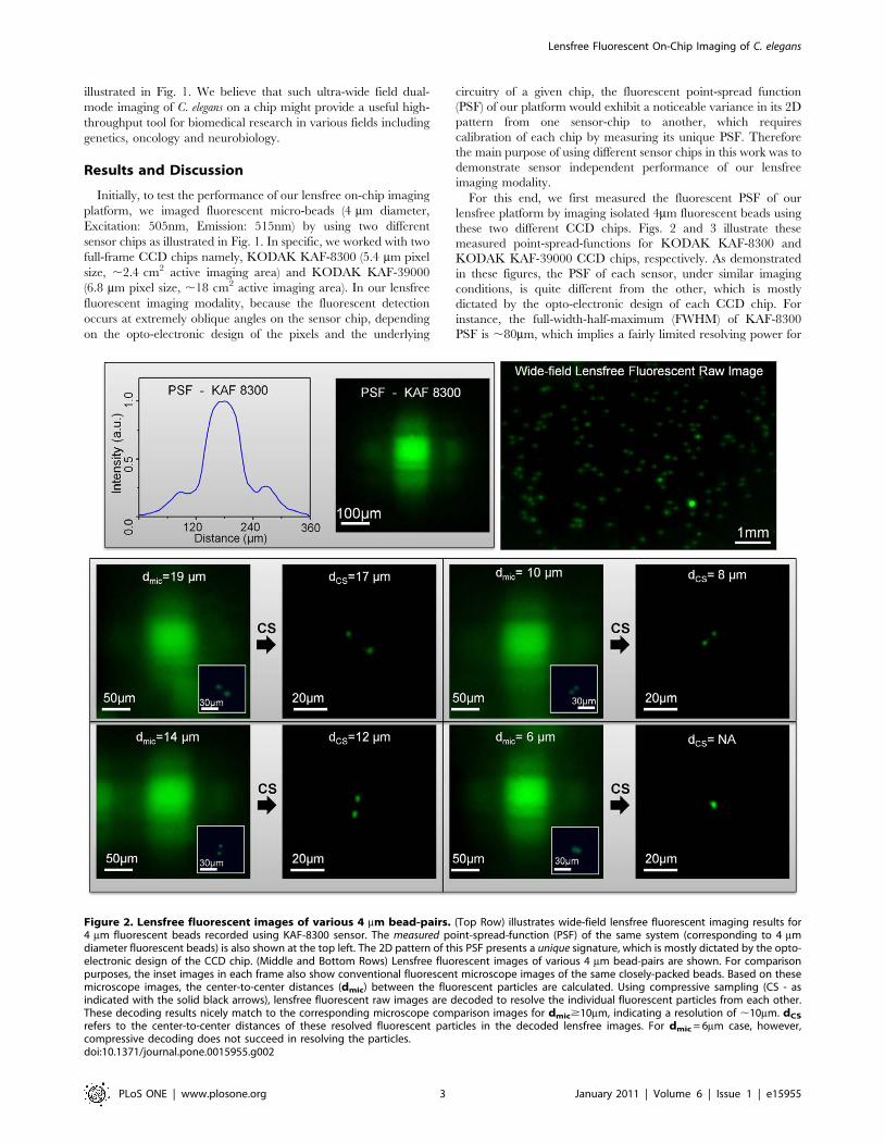
For this end, we first measured the fluorescent PSF of our
lensfree platform by imaging isolated 4mm fluorescent beads using
these two different CCD chips. Figs. 2 and 3 illustrate these
measured point-spread-functions for KODAK KAF-8300 and
KODAK KAF-39000 CCD chips, respectively. As demonstrated
in these figures, the PSF of each sensor, under similar imaging
conditions, is quite different from the other, which is mostly
dictated by the opto-electronic design of each CCD chip. For
instance, the full-width-half-maximum (FWHM) of KAF-8300
PSF is ,80mm, which implies a fairly limited resolving power for
Figure 2. Lensfree fluorescent images of various 4 mm bead-pairs. (Top Row) illustrates wide-field lensfree fluorescent imaging results for4 mm fluorescent beads recorded using KAF-8300 sensor. The measured point-spread-function (PSF) of the same system (corresponding to 4 mmdiameter fluorescent beads) is also shown at the top left. The 2D pattern of this PSF presents a unique signature, which is mostly dictated by the opto-electronic design of the CCD chip. (Middle and Bottom Rows) Lensfree fluorescent images of various 4 mm bead-pairs are shown. For comparisonpurposes, the inset images in each frame also show conventional fluorescent microscope images of the same closely-packed beads. Based on thesemicroscope images, the center-to-center distances (dmic) between the fluorescent particles are calculated. Using compressive sampling (CS - asindicated with the solid black arrows), lensfree fluorescent raw images are decoded to resolve the individual fluorescent particles from each other.These decoding results nicely match to the corresponding microscope comparison images for dmic$10mm, indicating a resolution of ,10mm. dCS
refers to the center-to-center distances of these resolved fluorescent particles in the decoded lensfree images. For dmic = 6mm case, however,compressive decoding does not succeed in resolving the particles.doi:10.1371/journal.pone.0015955.g002
Lensfree Fluorescent On-Chip Imaging of C. elegans
PLoS ONE | www.plosone.org 3 January 2011 | Volume 6 | Issue 1 | e15955
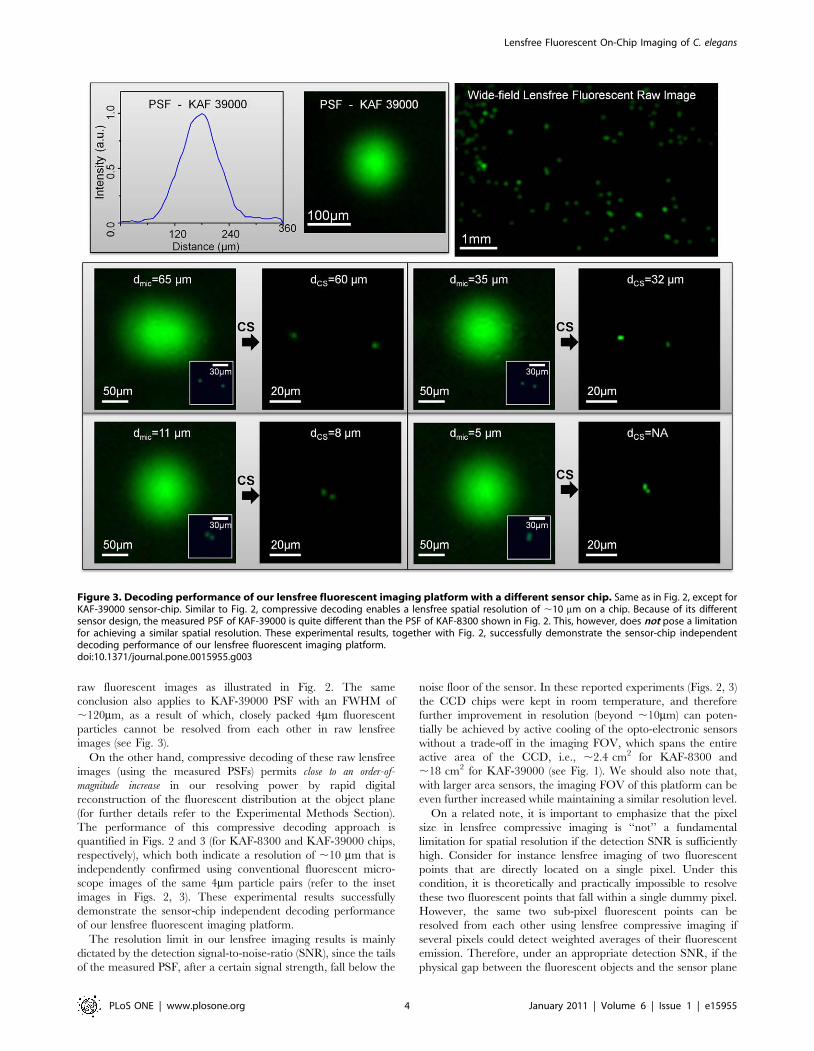
raw fluorescent images as illustrated in Fig. 2. The same
conclusion also applies to KAF-39000 PSF with an FWHM of
,120mm, as a result of which, closely packed 4mm fluorescent
particles cannot be resolved from each other in raw lensfree
images (see Fig. 3).
On the other hand, compressive decoding of these raw lensfree
images (using the measured PSFs) permits close to an order-of-
magnitude increase in our resolving power by rapid digital
reconstruction of the fluorescent distribution at the object plane
(for further details refer to the Experimental Methods Section).
The performance of this compressive decoding approach is
quantified in Figs. 2 and 3 (for KAF-8300 and KAF-39000 chips,
respectively), which both indicate a resolution of ,10 mm that is
independently confirmed using conventional fluorescent micro-
scope images of the same 4mm particle pairs (refer to the inset
images in Figs. 2, 3). These experimental results successfully
demonstrate the sensor-chip independent decoding performance
of our lensfree fluorescent imaging platform.
The resolution limit in our lensfree imaging results is mainly
dictated by the detection signal-to-noise-ratio (SNR), since the tails
of the measured PSF, after a certain signal strength, fall below the
noise floor of the sensor. In these reported experiments (Figs. 2, 3)
the CCD chips were kept in room temperature, and therefore
further improvement in resolution (beyond ,10mm) can poten-
tially be achieved by active cooling of the opto-electronic sensors
without a trade-off in the imaging FOV, which spans the entire
active area of the CCD, i.e., ,2.4 cm2 for KAF-8300 and
,18 cm2 for KAF-39000 (see Fig. 1). We should also note that,
with larger area sensors, the imaging FOV of this platform can be
even further increased while maintaining a similar resolution level.
On a related note, it is important to emphasize that the pixel
size in lensfree compressive imaging is ‘‘not’’ a fundamental
limitation for spatial resolution if the detection SNR is sufficiently
high. Consider for instance lensfree imaging of two fluorescent
points that are directly located on a single pixel. Under this
condition, it is theoretically and practically impossible to resolve
these two fluorescent points that fall within a single dummy pixel.
However, the same two sub-pixel fluorescent points can be
resolved from each other using lensfree compressive imaging if
several pixels could detect weighted averages of their fluorescent
emission. Therefore, under an appropriate detection SNR, if the
physical gap between the fluorescent objects and the sensor plane
Figure 3. Decoding performance of our lensfree fluorescent imaging platform with a different sensor chip. Same as in Fig. 2, except forKAF-39000 sensor-chip. Similar to Fig. 2, compressive decoding enables a lensfree spatial resolution of ,10 mm on a chip. Because of its differentsensor design, the measured PSF of KAF-39000 is quite different than the PSF of KAF-8300 shown in Fig. 2. This, however, does not pose a limitationfor achieving a similar spatial resolution. These experimental results, together with Fig. 2, successfully demonstrate the sensor-chip independentdecoding performance of our lensfree fluorescent imaging platform.doi:10.1371/journal.pone.0015955.g003
Lensfree Fluorescent On-Chip Imaging of C. elegans
PLoS ONE | www.plosone.org 4 January 2011 | Volume 6 | Issue 1 | e15955
can be increased to perform efficient spatial encoding of the
fluorescent objects, resolving of arbitrarily sub-pixel point sources
would be feasible. The fundamental limitation to this resolving
power is therefore the detection SNR, which determines how
many pixels can independently and accurately measure the
lensfree fluorescent contributions of the particles. Therefore, for
a practical SNR level, there is always an optimum gap range
between the object and sensor planes, which we found to be ,50–
200 mm for our CCD chips at room temperature.
After this initial characterization of the performance of our
wide-field fluorescent imaging platform, we next imaged trans-
genic C. elegans samples (refer to the Methods Section for details)
over a wide FOV using the same lensfree configuration depicted in
Fig. 1. The results of these imaging experiments are summarized
in Figs. 4 and 5 (as well as Appendix S1, see e.g., Figures S3 and
S4), which also provide conventional fluorescent microscope
images of the same samples for comparison purposes. As shown
in these figures, raw lensfree fluorescent signatures of the worms
are highly blurred due to our broad PSFs. However, using the
measured PSF of each platform, these lensfree signatures can be
compressively decoded to digitally yield much higher resolution
images of the fluorescent regions located within the C. elegans body,
which very well agree with the images obtained using a regular
lens-based fluorescent microscope (see Figs. 4, 5). These
experimental results successfully demonstrate the efficacy of our
compressive decoding approach to image transgenic C. elegans
samples using lensfree fluorescent on-chip imaging over an ultra-
wide FOV that covers the entire active area of the CCD chip (e.g.,
.2–8 cm2).
We should also note that, the presented on-chip microscopy
platform could potentially achieve multi-color imaging of
biological samples labeled with multiple distinct targets. In our
reported experiments, monochrome CCD chips were used to
achieve single color lensfree fluorescent imaging; however, the use
of e.g., RGB CCD chips could be utilized to image multiple colors.
Unlike conventional lens-based fluorescent microscopy the use of
an RGB sensor chip does not immediately bring color imaging
capability since without the use of any lenses, all the colors mix
with each other at the sensor plane due to unavoidable diffraction.
Therefore, lensfree fluorescent imaging might require a more
sophisticated compressive decoder to enable separation of multiple
colors using raw format RGB images, which was not at the focus of
this work.
In addition to fluorescent imaging, our lensfree on-chip
platform also permits holographic transmission imaging [18,19]
of the worms using the top interface of the same prism that is used
in fluorescent excitation (see Fig. 1). In this lensfree holographic
imaging approach, a spatially incoherent quasi-monochromatic
source such as a light-emitting-diode (LED) illuminates the
samples of interest after being spatially filtered by a large aperture
(e.g., 0.05–0.1 mm diameter). This incoherent light source picks
up partial spatial coherence that is sufficiently large to record
lensfree in-line holograms of the worms on the CCD chip. These
acquired in-line holograms can then be rapidly processed using
iterative recovery algorithms [18,19] to create lensfree transmis-
sion images of the C. elegans samples over the entire active area of
the sensor-chip, matching the imaging FOV of the fluorescent
channel. Figs. 4, 5 illustrate such reconstructed lensfree holo-
graphic images of the samples, where the lensfree fluorescent
images of the same worms were also digitally super-imposed,
creating a hybrid image of the C. elegans (i.e., both fluorescent and
transmission). It is evident from these lensfree images that the
spatial resolution of our platform is modest compared to a regular
lens-based microscope. On the other hand, the main advantages of
our platform are its ultra-wide FOV and compact on-chip
interface (see Fig. 1) which might provide an important match
for ultra-high throughput screening of C. elegans samples within
automated micro-fluidic systems.
Finally, we would like to also point to an alternative lensfree
imaging configuration that can also perform fluorescent imaging of
C. elegans samples on a chip. In this modified configuration (refer to
Appendix S1 and Figures S1, S2 for details), we make use of a
fiber-optic faceplate inserted underneath the sample substrate to
control and tailor the fluorescent PSF of the imaging platform.
Compressive decoding of transgenic C. elegans samples using these
altered fluorescent PSFs yields similar imaging results as in Figs. 4,
5 (see Appendix S1 and Figures S3, S4). This modified
configuration can conveniently tailor the fluorescent PSF of the
imaging platform to enhance the detection SNR, especially at
larger gaps between the object and sensor planes. This could be an
important advantage if physical separation between the sample
and the sensor-chip is required. Despite this important flexibility,
this faceplate based lensfree imaging approach has one limitation:
The holographic imaging channel is now significantly distorted
since the modes of the fiber-optic faceplate mess the complex
spatial frequency content of the holographic field propagating
toward the sensor-array. For further details on this modified
lensfree on-chip configuration and its C. elegans imaging results,
refer to Appendix S1.
In conclusion, we have demonstrated lensfree fluorescent
imaging of transgenic C. elegans over an ultra wide field-of-view
of .2–8 cm2 with a spatial resolution of ,10 mm. This is the first
time that a lensfree on-chip imaging platform has achieved
fluorescent imaging of C. elegans. We tested the efficacy of this on-
chip imaging approach with different types of opto-electronic
sensors to achieve a similar resolution level independent of the
imaging chip. Furthermore, we demonstrated that this wide FOV
lensfree fluorescent imaging platform can also perform bright-field
imaging of the same samples using partially-coherent lensfree
digital in-line holography. This unique combination permits ultra-
wide field dual-mode imaging of C. elegans which could provide a
useful tool for e.g., high-throughput screening applications.
Materials and Methods
Design of the fluorescent and holographic lensfree on-chip imaging system
Our lensfree imaging system utilizes a rhomboid prism to
achieve fluorescence excitation through its side facet as shown in
Fig. 1. After interacting with the entire body of the worm, pump
photons are rejected by TIR occurring at the bottom glass
substrate. To create a sufficient dark-field background, the weakly
scattered pump photons that do not obey TIR are also rejected by
an additional absorption filter (see Fig. 1), as a result of which only
the fluorescent emission from the objects is detected by the opto-
electronic sensor-array.
Note that unlike conventional lens-based fluorescent microsco-
py, the use of thin-film interference filters in our platform is not
trivial since rejection of pump photons in a lensfree imaging
configuration would require deposition of much thicker interfer-
ence films to block a large angular range of pump photons. This
not only increases the cost but also requires the use of considerably
thick substrates due to higher stress in the thicker film, which
significantly weakens the SNR of the fluorescent PSF, also
degrading the achievable resolution. Therefore, we avoided using
such interference based fluorescent filters, and instead, fabricated
absorption based filters that have dyes coated on ultra-thin glass
substrates (,30 mm).
Lensfree Fluorescent On-Chip Imaging of C. elegans
PLoS ONE | www.plosone.org 5 January 2011 | Volume 6 | Issue 1 | e15955
Lensfree Fluorescent On-Chip Imaging of C. elegans
PLoS ONE | www.plosone.org 6 January 2011 | Volume 6 | Issue 1 | e15955
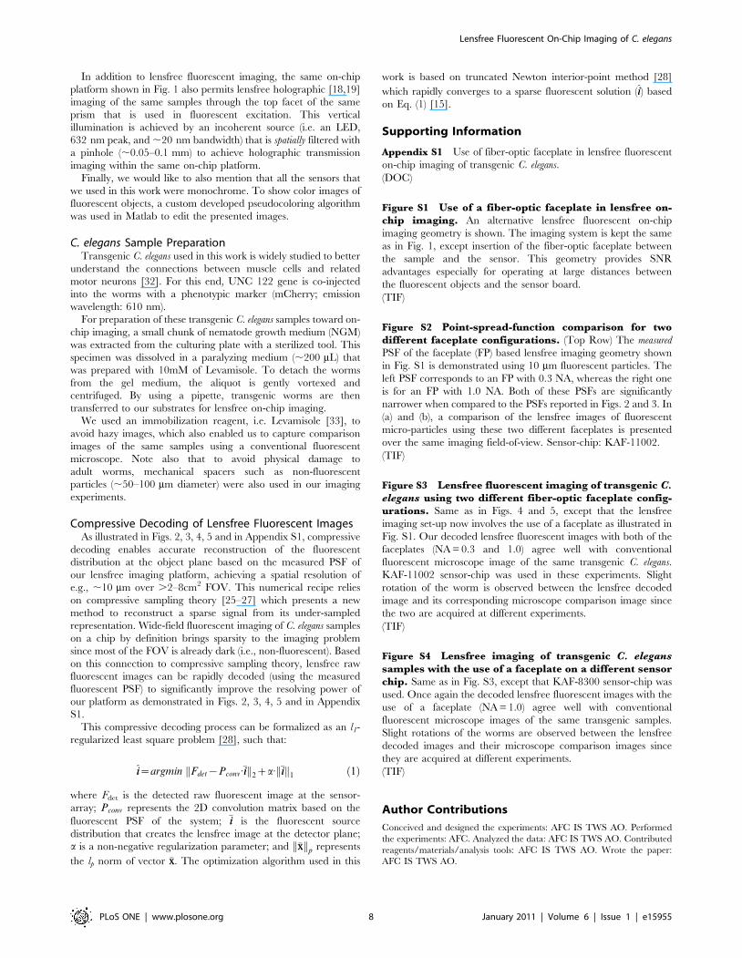
The fabrication recipe of these thin absorption filters includes
dissolving Orasol dyes in a small volume of cyclopentanone and
then adding KMPR 1005 Photoresist (,0.4 g ml21 dye concen-
tration), after which excess dye material was removed using a
0.45mm diameter mechanical filter [31]. This step is followed by
spin coating for 20 s at 2000 rpm, baking for 300 s at 100uC, flood
exposure at 13 mW/cm2 for 35 s, and finally baking for another
120 s at 100uC. Based on this recipe, we fabricated different long
pass absorption filters with cut-off wavelengths of 510nm, 540 nm
and 600 nm by using various types of Orasol dyes, including
Yellow 2RLN, Orange G, and Red BL, respectively. The rejection
ratio (,30–40 dB) of these fabricated absorption filters is
sufficiently large to create the necessary dark-field background
(together with TIR), making them rather useful in lensfree
fluorescent on-chip imaging applications.
Once fabricated, these absorption filters (total thickness
,40 mm; 10 mm filter+30 mm glass substrate) were placed directly
on the top of the active region of the CCD sensor, acting also as a
protector layer for the bare sensor surface. An additional
disposable ultra-thin glass substrate (,30 mm thick) was also used
between the sample and the absorption filter.
As for the excitation, an incoherent light source was used, which
was coupled from a Xenon lamp spectrally tuned to ,580 nm
(with 15 nm bandwidth) through a monochromator (MS260i,
Newport). During our experiments, the total power of excitation
was kept at ,1.0–1.5 mW for an FOV of .2 cm2.
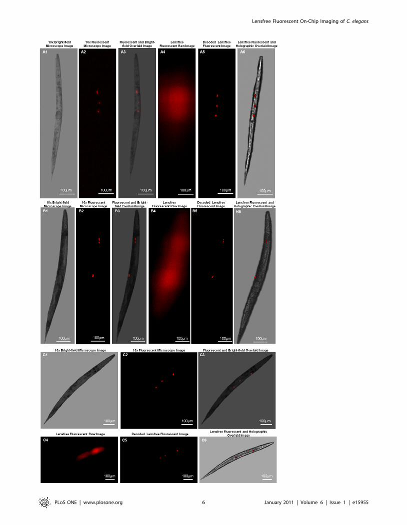
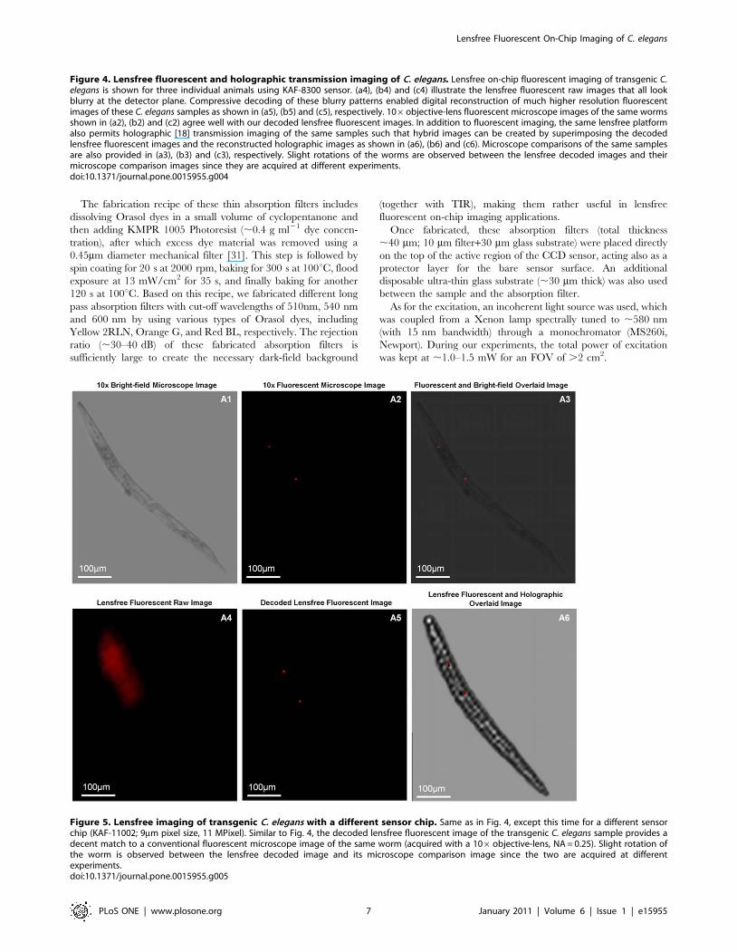
Figure 5. Lensfree imaging of transgenic C. elegans with a different sensor chip. Same as in Fig. 4, except this time for a different sensorchip (KAF-11002; 9mm pixel size, 11 MPixel). Similar to Fig. 4, the decoded lensfree fluorescent image of the transgenic C. elegans sample provides adecent match to a conventional fluorescent microscope image of the same worm (acquired with a 106objective-lens, NA = 0.25). Slight rotation ofthe worm is observed between the lensfree decoded image and its microscope comparison image since the two are acquired at differentexperiments.doi:10.1371/journal.pone.0015955.g005
Figure 4. Lensfree fluorescent and holographic transmission imaging of C. elegans. Lensfree on-chip fluorescent imaging of transgenic C.elegans is shown for three individual animals using KAF-8300 sensor. (a4), (b4) and (c4) illustrate the lensfree fluorescent raw images that all lookblurry at the detector plane. Compressive decoding of these blurry patterns enabled digital reconstruction of much higher resolution fluorescentimages of these C. elegans samples as shown in (a5), (b5) and (c5), respectively. 106objective-lens fluorescent microscope images of the same wormsshown in (a2), (b2) and (c2) agree well with our decoded lensfree fluorescent images. In addition to fluorescent imaging, the same lensfree platformalso permits holographic [18] transmission imaging of the same samples such that hybrid images can be created by superimposing the decodedlensfree fluorescent images and the reconstructed holographic images as shown in (a6), (b6) and (c6). Microscope comparisons of the same samplesare also provided in (a3), (b3) and (c3), respectively. Slight rotations of the worms are observed between the lensfree decoded images and theirmicroscope comparison images since they are acquired at different experiments.doi:10.1371/journal.pone.0015955.g004
Lensfree Fluorescent On-Chip Imaging of C. elegans
PLoS ONE | www.plosone.org 7 January 2011 | Volume 6 | Issue 1 | e15955
In addition to lensfree fluorescent imaging, the same on-chip
platform shown in Fig. 1 also permits lensfree holographic [18,19]
imaging of the same samples through the top facet of the same
prism that is used in fluorescent excitation. This vertical
illumination is achieved by an incoherent source (i.e. an LED,
632 nm peak, and ,20 nm bandwidth) that is spatially filtered with
a pinhole (,0.05–0.1 mm) to achieve holographic transmission
imaging within the same on-chip platform.
Finally, we would like to also mention that all the sensors that
we used in this work were monochrome. To show color images of
fluorescent objects, a custom developed pseudocoloring algorithm
was used in Matlab to edit the presented images.
C. elegans Sample PreparationTransgenic C. elegans used in this work is widely studied to better
understand the connections between muscle cells and related
motor neurons [32]. For this end, UNC 122 gene is co-injected
into the worms with a phenotypic marker (mCherry; emission
wavelength: 610 nm).
For preparation of these transgenic C. elegans samples toward on-
chip imaging, a small chunk of nematode growth medium (NGM)
was extracted from the culturing plate with a sterilized tool. This
specimen was dissolved in a paralyzing medium (,200 mL) that
was prepared with 10mM of Levamisole. To detach the worms
from the gel medium, the aliquot is gently vortexed and
centrifuged. By using a pipette, transgenic worms are then
transferred to our substrates for lensfree on-chip imaging.
We used an immobilization reagent, i.e. Levamisole [33], to
avoid hazy images, which also enabled us to capture comparison
images of the same samples using a conventional fluorescent
microscope. Note also that to avoid physical damage to
adult worms, mechanical spacers such as non-fluorescent
particles (,50–100 mm diameter) were also used in our imaging
experiments.
Compressive Decoding of Lensfree Fluorescent ImagesAs illustrated in Figs. 2, 3, 4, 5 and in Appendix S1, compressive
decoding enables accurate reconstruction of the fluorescent
distribution at the object plane based on the measured PSF of
our lensfree imaging platform, achieving a spatial resolution of
e.g., ,10 mm over .2–8cm2 FOV. This numerical recipe relies
on compressive sampling theory [25–27] which presents a new
method to reconstruct a sparse signal from its under-sampled
representation. Wide-field fluorescent imaging of C. elegans samples
on a chip by definition brings sparsity to the imaging problem
since most of the FOV is already dark (i.e., non-fluorescent). Based
on this connection to compressive sampling theory, lensfree raw
fluorescent images can be rapidly decoded (using the measured
fluorescent PSF) to significantly improve the resolving power of
our platform as demonstrated in Figs. 2, 3, 4, 5 and in Appendix
S1.
This compressive decoding process can be formalized as an l1-
regularized least square problem [28], such that:
ii~argmin Fdet{Pconv:�iik k2za: �iik k1 ð1Þ
where Fdet is the detected raw fluorescent image at the sensor-
array; Pconv represents the 2D convolution matrix based on the
fluorescent PSF of the system; �ii is the fluorescent source
distribution that creates the lensfree image at the detector plane;
a is a non-negative regularization parameter; and �xxk kp represents
the lp norm of vector �xx. The optimization algorithm used in this
work is based on truncated Newton interior-point method [28]
which rapidly converges to a sparse fluorescent solution (ii) based
on Eq. (1) [15].
Supporting Information
Appendix S1 Use of fiber-optic faceplate in lensfree fluorescent
on-chip imaging of transgenic C. elegans.
(DOC)
Figure S1 Use of a fiber-optic faceplate in lensfree on-chip imaging. An alternative lensfree fluorescent on-chip
imaging geometry is shown. The imaging system is kept the same
as in Fig. 1, except insertion of the fiber-optic faceplate between
the sample and the sensor. This geometry provides SNR
advantages especially for operating at large distances between
the fluorescent objects and the sensor board.
(TIF)
Figure S2 Point-spread-function comparison for twodifferent faceplate configurations. (Top Row) The measured
PSF of the faceplate (FP) based lensfree imaging geometry shown
in Fig. S1 is demonstrated using 10 mm fluorescent particles. The
left PSF corresponds to an FP with 0.3 NA, whereas the right one
is for an FP with 1.0 NA. Both of these PSFs are significantly
narrower when compared to the PSFs reported in Figs. 2 and 3. In
(a) and (b), a comparison of the lensfree images of fluorescent
micro-particles using these two different faceplates is presented
over the same imaging field-of-view. Sensor-chip: KAF-11002.
(TIF)
Figure S3 Lensfree fluorescent imaging of transgenic C.elegans using two different fiber-optic faceplate config-urations. Same as in Figs. 4 and 5, except that the lensfree
imaging set-up now involves the use of a faceplate as illustrated in
Fig. S1. Our decoded lensfree fluorescent images with both of the
faceplates (NA = 0.3 and 1.0) agree well with conventional
fluorescent microscope image of the same transgenic C. elegans.
KAF-11002 sensor-chip was used in these experiments. Slight
rotation of the worm is observed between the lensfree decoded
image and its corresponding microscope comparison image since
the two are acquired at different experiments.
(TIF)
Figure S4 Lensfree imaging of transgenic C. eleganssamples with the use of a faceplate on a different sensorchip. Same as in Fig. S3, except that KAF-8300 sensor-chip was
used. Once again the decoded lensfree fluorescent images with the
use of a faceplate (NA = 1.0) agree well with conventional
fluorescent microscope images of the same transgenic samples.
Slight rotations of the worms are observed between the lensfree
decoded images and their microscope comparison images since
they are acquired at different experiments.
(TIF)
Author Contributions
Conceived and designed the experiments: AFC IS TWS AO. Performed
the experiments: AFC. Analyzed the data: AFC IS TWS AO. Contributed
reagents/materials/analysis tools: AFC IS TWS AO. Wrote the paper:
AFC IS TWS AO.
Lensfree Fluorescent On-Chip Imaging of C. elegans
PLoS ONE | www.plosone.org 8 January 2011 | Volume 6 | Issue 1 | e15955
References
1. Lehner B, Crombie C, Tischler J, Fortunato A, Fraser AG (2006) Systematic
mapping of genetic interactions in Caenorhabditis elegans identifies common
modifiers of diverse signaling pathways. Nat Genet 38: 896–903.
2. Pinkston-Gosse J, Kenyon C (2007) DAF-16/FOXO targets genes that regulate
tumor growth in Caenorhabditis elegans. Nat Genet 39: 1403–1409.
3. Mellem JE, Brockie PJ, Madsen DM, Maricq AV (2008) Action potentials
contribute to neuronal signaling in C. elegans. Nat Neurosci 11: 865–867.
4. Yanik MF, Cinar H, Cinar HN, Chisholm AD, Jin Y, et al. (2004) Neurosurgery:
Functional regeneration after laser axotomy. Nature 432: 822.
5. Rohde CB, Zeng F, Gonzalez-Rubio R, Angel M, Yanik MF (2007) Microfluidic
system for on-chip high-throughput whole-animal sorting and screening at
subcellular resolution. Proceedings of the National Academy of Sciences 104:
13891–13895.
6. Crane MM, Chung K, Lu H (2009) Computer-enhanced high-throughput
genetic screens of C. elegans in a microfluidic system. Lab Chip 9: 38.
7. Chokshi TV, Bazopoulou D, Chronis N (2010) An automated microfluidic
platform for calcium imaging of chemosensory neurons in Caenorhabditis elegans.
Lab Chip Available at: http://pubs.rsc.org/en/Content/ArticleLanding/2010/
LC/C004658B. Accessed 3 September 2010.
8. Burns AR, Kwok TCY, Howard A, Houston E, Johanson K, et al. (2006) High-
throughput screening of small molecules for bioactivity and target identification
in Caenorhabditis elegans. Nat Protocols 1: 1906–1914.
9. Dupuy D, Bertin N, Hidalgo CA, Venkatesan K, Tu D, et al. (2007) Genome-
scale analysis of in vivo spatiotemporal promoter activity in Caenorhabditis
elegans. Nat Biotech 25: 663–668.
10. Rea SL, Wu D, Cypser JR, Vaupel JW, Johnson TE (2005) A stress-sensitive
reporter predicts longevity in isogenic populations of Caenorhabditis elegans.
Nat Genet 37: 894–898.
11. Doitsidou M, Flames N, Lee AC, Boyanov A, Hobert O (2008) Automated
screening for mutants affecting dopaminergic-neuron specification in C. elegans.
Nat Methods 5: 869–872.
12. Pulak R (2006) Techniques for analysis, sorting, and dispensing of C. elegans on
the COPAS flow-sorting system. Methods Mol Biol 351: 275–286.
13. Semple JI, Garcia-Verdugo R, Lehner B (2010) Rapid selection of transgenic C.
elegans using antibiotic resistance. Nat Meth 7: 725–727.
14. Coskun AF, Su T, Ozcan A (2010) Wide field-of-view lens-free fluorescent
imaging on a chip. Lab Chip 10: 824–827.
15. Coskun AF, Sencan I, Su T, Ozcan A (2010) Lensless wide-field fluorescent
imaging on a chip using compressive decoding of sparse objects. Opt Express 18:
10510–10523.
16. Seo S, Su T, Tseng DK, Erlinger A, Ozcan A (2009) Lensfree holographic
imaging for on-chip cytometry and diagnostics. Lab Chip 9: 777–787.
17. Seo S, Isikman SO, Sencan I, Mudanyali O, Su T, et al. (2010) High-Throughput Lens-Free Blood Analysis on a Chip. Analytical Chemistry 82:
4621–4627.18. Isikman SO, Sencan I, Mudanyali O, Bishara W, Oztoprak C, et al. (2010)
Color and monochrome lensless on-chip imaging of Caenorhabditis elegans overa wide field-of-view. Lab Chip 10: 1109–1112.
19. Mudanyali O, Tseng D, Oh C, Isikman SO, Sencan I, et al. (2010) Compact,
light-weight and cost-effective microscope based on lensless incoherentholography for telemedicine applications. Lab Chip 10: 1417–1428.
20. Tseng D, Mudanyali O, Oztoprak C, Isikman SO, Sencan I, et al. (2010)Lensfree microscopy on a cellphone. Lab Chip 10: 1787.
21. Su T, Isikman SO, Bishara W, Tseng D, Erlinger A, et al. (2010) Multi-angle
lensless digital holography for depth resolved imaging on a chip. Opt Express 18:9690–9711.
22. RICHARDSON WH (1972) Bayesian-Based Iterative Method of ImageRestoration. J Opt Soc Am 62: 55–59.
23. Lucy LB (1974) An iterative technique for the rectification of observed
distributions. The Astronomical Journal 79: 745.24. Biggs DSC, Andrews M (1997) Acceleration of iterative image restoration
algorithms. Appl Opt 36: 1766–1775.25. Donoho D (2006) Compressed sensing. Information Theory, IEEE Transactions
on 52: 1289–1306.26. Candes E, Tao T (2006) Near-Optimal Signal Recovery From Random
Projections: Universal Encoding Strategies? Information Theory, IEEE
Transactions on 52: 5406–5425.27. Candes EJ, Romberg JK, Tao T (2006) Stable signal recovery from incomplete
and inaccurate measurements. Comm Pure Appl Math 59: 1207–1223.28. Seung-JeanKim, Koh K, Lustig M, Boyd S, Gorinevsky D (2007) An Interior-
Point Method for Large-Scale l1-Regularized Least Squares. Selected Topics in
Signal Processing, IEEE Journal of 1: 606–617.29. Candes E, Romberg J, Tao T (2006) Robust uncertainty principles: exact signal
reconstruction from highly incomplete frequency information. InformationTheory, IEEE Transactions on 52: 489–509.
30. Bioucas-Dias J, Figueiredo M (2007) A New TwIST: Two-Step IterativeShrinkage/Thresholding Algorithms for Image Restoration. Image Processing,
IEEE Transactions on 16: 2992–3004.
31. Richard C, Renaudin A, Aimez V, Charette PG (2009) An integrated hybridinterference and absorption filter for fluorescence detection in lab-on-a-chip
devices. Lab Chip 9: 1371–1376.32. Loria PM, Hodgkin J, Hobert O (2004) A Conserved Postsynaptic Transmem-
brane Protein Affecting Neuromuscular Signaling in Caenorhabditis elegans.
J Neurosci 24: 2191–2201.33. Kural C, Nonet ML, Selvin PR (2009) FIONA on C. elegans. Biochemistry 48:
4663.
Lensfree Fluorescent On-Chip Imaging of C. elegans
PLoS ONE | www.plosone.org 9 January 2011 | Volume 6 | Issue 1 | e15955