Fluorescent electronic - WordPress.com
22
-
Upload
khangminh22 -
Category
Documents
-
view
0 -
download
0
Transcript of Fluorescent electronic - WordPress.com


Dimensions in mm
Fluorescent electronic
EB-PRIMALUME
EB-PRIMALUME
DefinitionSlim, lightweight high-frequency (> 42kHz) electronic ballast for TLD fluorescent lamps at 220 – 240V 50/60Hz.
Features & Benefits:
Applications
TYPE A B C D E
Up to 25% reduction in energy consumption at constant luminous flux compared with conventional gear. The combination of EB-P and Master TL-D lamps offer low energy consumption resulting in reduced cost of ownership. Piece of mind by excelling the current industry standard for electronic ballast, the ballast offers power factor is more than 0.97 and Total Harmonic Distortion THD is < 10%.System reliability for ignition and operation is achieved with the programmed start: (warm start) ignition method. Preheating the lamp electrodes; this enables the lamps to be switched on and off without reducing useful life.Up to50% longer lamp life than using conventional ballasts.EB-P is Equipped with electrode heating cut-off circuit, ensuring optimal lamp operation with respect to lumen curve of the lamp and reduction in system energy losses.Smart power: offering a constant light output, independent of mains voltage fluctuations.Unit is protected against excessive mains voltages and incorrect connections.Automatic stop circuit is activated within five seconds in case of lamp failure (Safety stop); once the lamp has been replaced, the ballast resets automatically.
•
•
•
••
•
•
•
Typical areas of application include:• Department stores, Malls, Shops, Hyper-and Supermarkets• Office buildings, Banks, government ministries• Industrial premises
Philips qualityThis assures optimum quality regarding:• System supplier
As manufacturer of lamps, electronic control gear and lighting control equipment, Philips ensures that, from the earliest development stage, optimum lamp/ballast performance is maintained.
• International standards Philips Electronic Ballast’s complies with all relevant international standards and regulations.
E
B
D
EB-P 118 TLD ICC 265 280 30 28 4.2
EB-P 218 TLD ICC 265 280 30 28 4.2
EB-P 3/418 TLD ICC 265 280 39 28 4.2
EB-P 136 TLD ICC 265 280 30 28 4.2
EB-P 236 TLD ICC 265 280 30 28 4.2
EB-P 336 TLD ICC 265 280 39 28 4.2
EB-P 158 TLD ICC 265 280 30 28 4.2
EB-P 258 TLD ICC 265 280 30 28 4.2
TECHNOLOGY
S&E

2
Compliances and approvals
• RFI<30 MHz EN 55015 (EMC)• RFI>30 MHz EN 55015 Ed 7.1 * * Note: ballast range will comply to Ed. 7.1 per mid 2008 Mandatory per Aug 2010.• Harmonics IEC 61000-3-2• Immunity EN 61547 IEC 61000-4-4 Class3 IEC 61000-4-5 Class3 IEC 61000-4-11• Safety IEC 61347-2-3• Performance IEC 60929: 2006 IEC 60081 (Program start)• Vibration & bump tests EN 60068-2-6-FC EN 60068-2-29-Eb
• Quality standard ISO 9001• Environmental standard ISO 14001 RoHS compliant Humidity IEC 61347-1 EMI CISPR 15• Approval marks ENEC, EMV-VDE AS/NZS C-Tick CCC• Temp. declared
thermally protected EN 61347-1 • CE marking
110
Technical data in relation to energy saving (all typical values at Vmains =230V)
tbc = to be confirmed
tbc = to be confirmed
Lamp Qty. of Ballast System Lamp Ballast CELMA THD
Lamps Power Power Losses
W W W EEI
Lamp Qty. of Ballast Power Ballast Oper Wiring
Lamps Factor Lumen Freq diagram
Factor (nom) kHz fig.
Technical data for installation Mains operationRated mains voltage 220-240 VWith tolerances for performance -8% +6% 202-254 VWith tolerances for safety: +/- 10% 198-264 V (3)
(3) Ignition and operation possible between 176-276 V Mains frequency 50/60 Hz
DC voltage operation during emergency back-up YesFor limited time (48Hrs) only: Required battery voltage for guaranteed ignition 198V - 254V Required battery voltage for burning lamps 176V - 254V
Notes:1. For continuous DC application, an external fuse should be used in the luminaires2. Continuous low DC voltages (<198V) can influence the lifetime of the ballast
TL-D 18W 1 EB-P 118 TLD ICC 0,95 1.00 46 1
TL-D 18W 2 EB-P 218 TLD ICC 0,98 1.05 46 2
TL-D 18W(tbc) 3 EB-P 3/418 TLD ICC (0,98) (0.95-1.05) (42) (3)
TL-D 18W(tbc) 4 EB-P 3/418 TLD ICC (0,98) (0.95-1.05) (42) (4)
TL-D 36W 1 EB-P 136 TLD ICC 0,98 1.00 46 1
TL-D 36W 2 EB-P 236 TLD ICC 0,98 1.00 46 2
TL-D 36W(tbc) 3 EB-P 336 TLD ICC (0,98) (0.95-1.05) (42) (3)
TL-D 58W 1 EB-P 158 TLD ICC 0,99 1.00 46 1
TL-D 58W 2 EB-P 258 TLD ICC 0,99 1.00 46 2
Fluorescent electronic EB-PRIMALUME
TL-D 18W 1 EB-P 118 TLD ICC 19 16.0 3.0 A2 10%
TL-D 18W 2 EB-P 218 TLD ICC 36 32.5 3.5 A2 10%
TL-D 18W (tbc) 3 EB-P 3/418 TLD ICC (57) (49.0) (8.0) A2 10%
TL-D 18W (tbc) 4 EB-P 3/418 TLD ICC (75) (65.5) (9.5) A2 10%
TL-D 36W 1 EB-P 136 TLD ICC 36 32.5 3.5 A2 10%
TL-D 36W 2 EB-P 236 TLD ICC 72 64.5 7.5 A2 10%
TL-D 36W (tbc) 3 EB-P 336 TLD ICC (108) (97) (11.0) A2 10%
TL-D 58W 1 EB-P 158 TLD ICC 55 50.5 4.5 A2 10%
TL-D 58W 2 EB-P 258 TLD ICC 108 100 8.0 A2 10%

3
Technical data for installation Earth leakage current < 0.5 mA per ballast
Total Harmonic Distortion (THD) < 10%
Ignition time Typically 1.6 sec.
Constant light operation In case of AC mains voltage fluctuations, within 202-254 V, the luminous flux Changes by a maximum of 5 %
Overvoltage protection 48 hrs at 320 V AC 2 hrs at 350 V AC
Cable Capacity Max 200pF between lamp wires lp-lp Max 200pF between lamp wires and earth lp-gnd EMI precautions have to be taken (7)
Dual fixture: master-slave Possible, in general a maximum of 2m lamp wires between ballast and lamp is allowed
Automatic restart after lamp yes: tested with a dip down to 30% replacement or voltage dip with a duration of 10 mains cycles
Insulation resistance test 500 V DC from Line/Neutral to Earth (not between Line and Neutral) Note: Ensure that the neutral is reconnected again after above mentioned test is carried out and before the installation is put in operation
Lamp current crest factor < 1.7
Mains current at 220/230V/240VBallast Input current 220 / 230 / 240V
A
EB-P 118 TLD ICC (1x18W TL-D) 0.09 / 0.09 / 0.07
EB-P 218 TLD ICC (2x18W TL-D) 0.17 / 0.16 / 0.14
EB-P 3/418 TLD ICC (3x18W TL-D) (tbc) / (0.25)/ (0.22)
EB-P 3/418 TLD ICC (4x18W TL-D) (tbc) / (0.33) / (0.30)
EB-P 136 TLD ICC (1x36W TL-D) 0.18 / 0.16 / 0.15
EB-P 236 TLD ICC (2x36W TL-D) 0.34 / 0.32 / 0.29
EB-P 336 TLD ICC (3x36W TL-D) (tbc) / (0.47) / (0.44)
EB-P 158 TLD ICC (1x58W TL-D) 0,27 / 0.23 / 0.22
EB-P 258 TLD ICC (2x58W TL-D) 0.51 / 0.48 / 0.44
Inrush currentballast Max. quantity of Inrush current
ballast per ½ value
Miniature Circuit time at typical
Breaker mains
Type B16 A impedance
EB-P 118 TLD ICC 1x18W TL-D 28 25A/200 µS
EB-P 218 TLD ICC 2x18W TL-D 28 25A/200 µS
EB-P 3/418 TLD ICC 3x18W TL-D 28 25A/200 µS
EB-P 3/418 TLD ICC 4x18W TL-D 12 35A/250 µS
EB-P 136 TLD ICC 1x36W TL-D 28 25A/200 µS
EB-P 236 TLD ICC 2x36W TL-D 28 25A/200 µS
EB-P 336 TLD ICC 3x36W TL-D 12 35A/250 µS
EB-P 158 TLD ICC 1x58W TL-D 28 25A/200 µS
EB-P 258 TLD ICC 2x58W TL-D 12 35A/250 µS
Conversion table for max. quantities of ballasts on other types of Miniature Circuit BreakerMCB Type Relative quantity of
ballasts
B 16A 100% (see table above)
B 10A 63%
C 16A 170%
C 10A 104%
L, I 16A 108%
L, I 10A 65%
G, U, II 16A 212%
G, U, II 10A 127%
K, III 16A 254%
K, III 10A 154%
Data is based on a mains supply with an impedance of 400 mΩ (equal to 15 m cable of 2.5mm2 and another 20m to the middle of the power distribution), under worst case conditions. With an impedance of 800 mΩ the number of ballasts can be increased by 10%.Measurements will be verified in real installations; therefore data are subject to change. In some cases the maximum number of ballasts is not determined by the MCB but by the maximum electrical load of the lighting installation. Note that the maximum number of ballasts is given when these are all switched on the same moment, i.e. by a wall switch. Measurements were carried out on single-pole MCB’s. For multi-pole MCB’s it is advisable to reduce the number of ballasts by 20%.The maximum number of ballasts which can be connected to one Residual Current Detector of 30mA is 30.The average cable capacity Lp-Gnd is 100pF per meter for standard installation wire Diameter 1.0 mm (bundled lamp wiring situation). For more information regarding this. subject consult the Philips Application guide to fluorescent lamp control gear (3222 635 59771 *May 2006)
Notes1.
2.
3.
4.
5.
6.
7.
Fluorescent electronic EB-PRIMALUME

Fluorescent electronic
4
Technical data for design and mounting in fixturesTemperaturesTemperature range to ignite lamp -25° to +50 °Cwith ignition aid
Storage Temperature -40° to +50 °CLifetime 50,000 HrsFailure rate less than 0.2% per 1000hrs of operation Max t case 70 °C
Lifetime of a ballast depends on the temperature of the ballast. This means there is a relation between the Tc point on the ballast and its lifetime. For more information regarding this subject consult the Philips Application guide to fluorescent lamp control gear (3222 635 59771 *May 2006)
Hum and noise level inaudible (< 30 dBa at 1 meter)
Outdoor use Ballast IP=23, in outdoor applications the Luminaires has to be sufficient IP rated. Permitted humidity is tested according to IEC 61347-1 par 11 Note that no moisture or condensation may Enter the ballast.
Connector type:Connection wiring is greatly simplified through use of insert contacts with pushbuttons. Earth connection can be made via housing.
Wire lengths:For optimal performance, note that following wires need to be kept short:For one lamp circuits keep wires to terminals 1 and 2 shortFor two lamp circuits keep wires to terminals 1, 2, 5 and 6 shortFor triple and quad lamp circuits keep wires to terminals 1, 2, 5, 6, 9 and 10 short
Wire cross-section:Mains 0.5 mm – 1.5 mm2
Lamp(s) connector 0.5 mm – 1.5 mm2
Strip length 9.0 – 10.0 mm
Wiring diagrams
Figure 1 Figure 2
Ordering and packing dataBallast Ordering weight Bulk packing
Number Qty. Dimensions Volume Weight EAN code EOC
LxWxH Gross
kg. pcs cm m3 kg
EB-P 118 TLD ICC 9137 130 20266 0.20 12 32.8x20.6x8.7 0.0058 2.9 8710163062389 871016306238930
EB-P 218 TLD ICC 9137 130 20366 0.20 12 32.8x20.6x8.7 0.0058 3.2 8710163062402 871016306240230
EB-P 3/418 TLD ICC 9137 130 20466 tbc 10 32.8x22.1x8.7 0.0063 3.1 XXXXXXXXXX41 XXXXXXXXXX130
EB-P 136 TLD ICC 9137 130 20666 0.20 12 32.8x20.6x8.7 0.0058 3.0 8710163062426 871016306242630
EB-P 236 TLD ICC 9137 130 20766 0.20 12 32.8x20.6x8.7 0.0058 3.0 8710163062440 871016306244030
EB-P 336 TLD ICC 9137 130 20866 tbc 10 32.8x22.1x8.7 0.0063 3.1 XXXXXXXXXX40 XXXXXXXXXXX30
EB-P 158 TLD ICC 9137 130 20966 0.20 12 32.8x20.6x8.7 0.0058 3.2 8710163062464 871016306246430
EB-P 258 TLD ICC 9137 130 21066 0.25 12 32.8x20.6x8.7 0.0058 3.3 8710163062488 871016306248830
Earthing Earthing of the ballast in a luminaires is necessary for EMC (Electromagnetic Compatibility)
The ballasts that are thermally protected use a protective method of another type providing equivalent thermal protection.
Fluorescent electronic EB-PRIMALUME
Dimensions in mm
EB-SELECTALUME
EB-SELECTALUME
TYPE A B C D E
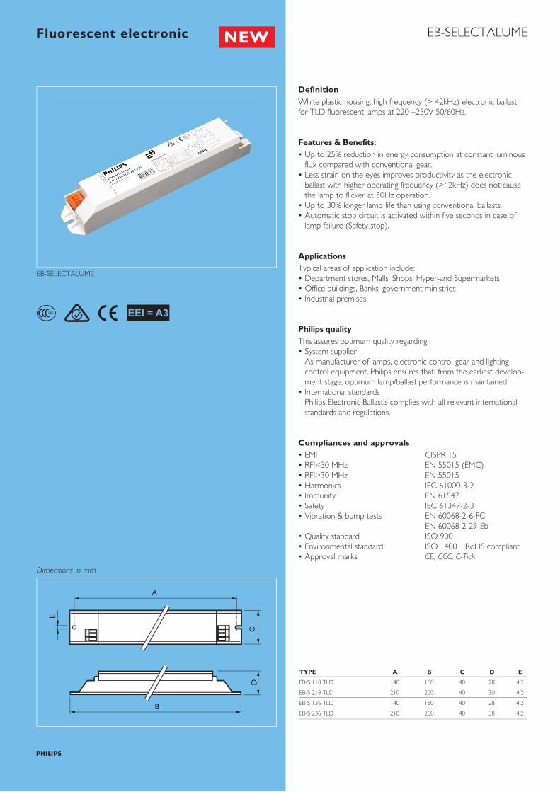
DefinitionWhite plastic housing, high frequency (> 42kHz) electronic ballast for TLD fluorescent lamps at 220 –230V 50/60Hz.
Features & Benefits:• Up to 25% reduction in energy consumption at constant luminous
flux compared with conventional gear.• Less strain on the eyes improves productivity as the electronic
ballast with higher operating frequency (>42kHz) does not cause the lamp to flicker at 50Hz operation.
• Up to 30% longer lamp life than using conventional ballasts.• Automatic stop circuit is activated within five seconds in case of
lamp failure (Safety stop).
ApplicationsTypical areas of application include:• Department stores, Malls, Shops, Hyper-and Supermarkets• Office buildings, Banks, government ministries• Industrial premises
Philips qualityThis assures optimum quality regarding:• System supplier
As manufacturer of lamps, electronic control gear and lighting control equipment, Philips ensures that, from the earliest develop-ment stage, optimum lamp/ballast performance is maintained.
• International standards Philips Electronic Ballast’s complies with all relevant international standards and regulations.
Compliances and approvals• EMI CISPR 15• RFI<30 MHz EN 55015 (EMC)• RFI>30 MHz EN 55015 • Harmonics IEC 61000-3-2• Immunity EN 61547• Safety IEC 61347-2-3• Vibration & bump tests EN 60068-2-6-FC, EN 60068-2-29-Eb• Quality standard ISO 9001• Environmental standard ISO 14001, RoHS compliant• Approval marks CE, CCC, C-Tick
E
B
D
S&E
EB-S 118 TLD 140 150 40 28 4.2
EB-S 218 TLD 210 200 40 30 4.2
EB-S 136 TLD 140 150 40 28 4.2
EB-S 236 TLD 210 200 40 38 4.2
Fluorescent electronic

2
Technical data for installation Mains operationRated mains voltage 220-230 VWith tolerances for safety: ± 10% 198-253 V (3)
(3) Ignition and operation possible 176-264 V betweenMains frequency 50/60 Hz
DC voltage operation during Noemergency back-upFor limited time (48Hrs) only:
Required battery voltage for 198V - 254Vguaranteed ignition Required battery voltage for 176V - 254V burning lamps
Notes:1. For continuous DC application, an external fuse should be used in
the luminaires2. Continuous low DC voltages (<198V) can influence the lifetime of
the ballast
Earth leakage current < 0.5 mA per ballast
Total Harmonic Distortion (THD) < 15%
Ignition time Typically 1.6 sec.
Constant light operation In case of AC mains voltage fluctuations, within 202-254 V, the luminous flux Changes by a maximum of ± 5%
Overvoltage protection 48 hrs at 270 V AC
Cable Capacity Max 120pF between lamp wires lp-lp Max 120pF between lamp wires and earth lp-gnd
Dual fixture: master-slave Possible, in general a maximum of 2m lamp wires between ballast and lamps are allowed
Automatic restart after lamp No replacement
Insulation resistance test 500 V DC from Line/Neutral to Earth (not between Line and Neutral) Note: Ensure that the neutral is reconnected again after above mentioned test is carried out and before the installation is put in operation
Lamp current crest factor < 1.7
Technical data in relation to energy saving (all typical values at Vmains =230V)Lamp Qty. of Ballast System Lamp Ballast CELMA THD
Nominal* Lamps Power Power Losses
W W W W EEI
TL-D 18W 1 EB-S 118 TLD 19 16.0 3.0 A3 15%
TL-D 18W 2 EB-S 218 TLD 37 32.0 4.0 A3 15%
TL-D 36W 1 EB-S 136 TLD 37 32.0 4.0 A3 15%
TL-D 36W 2 EB-S 236 TLD 72 64.0 8.0 A3 15%
Lamp Qty. of Ballast Power Ballast Oper Wiring
Lamps Factor Lumen Freq diagram
kHz fig.
TL-D 18W 1 EB-S 118 TLD 0.98 1.00 44 1
TL-D 18W 2 EB-S 218 TLD 0.98 1.00 44 2
TL-D 36W 1 EB-S 136 TLD 0.98 1.00 44 1
TL-D 36W 2 EB-S 236 TLD 0.98 1.00 44 2
Mains current at 220/230V/240VBallast Input current at 220 / 230 / 240
A
EB-S 118 TLD (1x18W TL-D) 0.08 / 0.09 / 0.07
EB-S 218 TLD (2x18W TL-D) 0.17 / 0.18 / 0.14
EB-S 136 TLD (1x36W TL-D) 0.16 / 0.17 / 0.15
EB-S 236 TLD (2x36W TL-D) 0.31 / 0.32 / 0.29
Inrush current Max. quantity of ballast per Inrush current ½ value
Miniature Circuit Breaker time at typical mains
Type B16 A impedance
EB-S 118 TLD (1x18W TL-D) 24 25A/200 µS
EB-S 218 TLD (2x18W TL-D) 24 25A/200 µS
EB-S 136 TLD (1x36W TL-D) 24 25A/200 µS
EB-S 236 TLD (2x36W TL-D) 24 25A/200 µS
EB-SELECTALUMEFluorescent electronic

Conversion table for max. quantities of ballasts on other types of Miniature Circuit BreakerMCB Type Relative quantity of ballasts
B 16A 100%(see table above)
B 10A 63%
C 16A 170%
C 10A 104%
L, I 16A 108%
L, I 10A 65%
G, U, II 16A 212%
G, U, II 10A 127%
K, III 16A 254%
K, III 10A 154%
3
Notes:1. Data is based on a mains supply with an impedance of 400 mΩ
(equal to 15 m cable of 2.5mm2 and another 20m to the middle of the power distribution), under worst case conditions. With an impedance of 800 mΩ the number of ballasts can be increased by 10%.
2. Measurements will be verified in real installations; therefore data are subject to change.
3. In some cases the maximum number of ballasts is not determined by the MCB but by the maximum electrical load of the lighting installation.
4. Note that the maximum number of ballasts is given when these are all switched on the same moment, i.e. by a wall switch.
5. Measurements were carried out on single-pole MCB’s. For multi-pole MCB’s it is advisable to reduce the number of ballasts by 20%.
6. The maximum number of ballasts which can be connected to one Residual Current Detector of 30mA is 30.
7. The average cable capacity Lp-Gnd is 100pF per meter for standard installation wire Diameter 1.0 mm (bundled lamp wiring situation). For more information regarding this subject consult the Philips Application guide to fluorescent lamp control gear.
Technical data for design and mounting in fixturesTemperaturesTemperature range to ignite lamp -55 C to +50 Cwith ignition aid
Storage Temperature -40 C to +50 CLifetime 30,000 HrsFailure rate less than 0.2% per 1000hrs of operation Max t case 65 C
Lifetime of a ballast depends on the temperature of the ballast. This means there is a relation between the Tc point on the ballast and its lifetime. For more information regarding this subject consult the Philips Application guide to fluorescent lamp control gear (3222 635 59771 *May 2006)
Hum and noise level inaudible (< 30 dBa at 1 meter)
Outdoor use Ballast IP=23, in outdoor applications the Luminaires has to be sufficient IP rated. Permitted humidity is tested according to IEC 61347-1 par 11 Note that no moisture or condensation may Enter the ballast.
Earthing Earthing of the ballast in a luminaires is necessary for EMC (Electromagnetic Compatibility)
The ballasts that are thermally protected use a protective method of another type providing equivalent thermal protection.
EB-SELECTALUMEFluorescent electronic
Connector type:Connection wiring is greatly simplified through use of insert contacts with push buttons. Earth connection can be made via housing.
Wire lengths:For optimal performance, note that following wires need to be kept short;For one lamp circuits keep wires to terminals 1 and 2 short;For two lamp circuits keep wires to terminals 1,2,3 and 4 short.
Wiring diagrams
Fig. 1 Fig. 2
Wire cross-section:Mains 0.5mm – 1.5mm2
Lamp(s) connector 0.5mm – 1.5mm2
Strip length 9.0 – 10.0 mm
EB-SEB-S

4
Ordering and packing dataBallast Ordering weight Packing
Number Qty. Dimensions Volume Weight EAN code EOC
L x W x H Gross
kg pcs cm m3 kg
EB-S 118 TLD 9137 130 21314 0.160 12 32.8x20.6x8.7 0.0058 2.9 8710163063928 871016306393530
EB-S 218 TLD 9137 130 21414 0.250 12 32.8x20.6x8.7 0.0058 3.2 8710163063966 871016306396630
EB-S 136 TLD 9137 130 21514 0.160 12 32.8x20.6x8.7 0.0058 3.0 8710163063942 871016306395930
EB-S 236 TLD 9137 130 21614 0.250 12 32.8x20.6x8.7 0.0058 3.0 8710163063980 871016306399730
EB-SELECTALUMEFluorescent electronic

Fluorescent electronic
EB-CERTALUME TLD
EB-CERTALUME
Type A B C D E
DefinitionCompact, lightweight, high-frequency electronic ballasts for TLDfluorescent lamps, for applications with 220V mains voltage.
Description• Up to 20% reduction in energy consumption at equal luminous
flux compared with conventional gear• Flicker-free, rapid start, no ignitor needed• Safe & reliable, up to 20,000hrs longer life• Multi-voltage ballast• Automatic stop circuit is activated in case of lamp failure• EMI CISPR 15 compliance, lower electromagnetic interference• Lower Harmonic, GB 17625.1 compliance
ApplicationsTypical areas of application include:• Department stores, shops, supermarkets, convenient stores and
public areas• Industrial premises, office buildings• Corridors, lighting boxes
Ideal for areas with low switching frequency (maximum 3 times aday)
Philips qualityThis implies optimum quality regarding• System supplier
As manufacturers of lamps and electronic control gear, Philips ensures that, from the earliest development stage, optimum lamp/ballast performance is maintained.
• CCC compliance
Compliances and approvals• RFI<30MHz CISPR 15• Harmonic GB 17625.1• Safety GB 19510.4, GB 19510.1• Quality standard ISO 9001• Environmental standard ISO 14001• CCC
EB-CertaLume 118 TLD 220V 140 150 40 28 4.2
EB-CertaLume 218 TLD 220V 140 150 40 28 4.2
EB-CertaLume 136 TLD 220V 140 150 40 28 4.2
EB-CertaLume 236 TLD 220V 200 210 40 30 4.2
Dimensions in mm
E
B
D
S&E

Fluorescent electronic EB-CERTALUME
Technical data in relation to energy savingLamp Qty. of Ballast System Lamp Ballast Wiring
Lamps Power Power Losses Diagram
W W W fig.
TLD 18W I EB-CertaLume 118 TLD 220V 18 16 2 1
TLD 18W 2 EB-CertaLume 218 TLD 220V 36 16 4 2
TLD 36W I EB-CertaLume 136 TLD 220V 36 32 4 1
TLD 36W 2 EB-CertaLume 236 TLD 220V 72 32 8 2
Lamp Qty. of Ballast Power Ballast THD Oper
Lamps factor Lumen Freq
Factor KHz
TL-D 18W 1 EB-CertaLume 118 TLD 220V > 0.95 0.95 < 25% > 42
TL-D 18W 2 EB-CertaLume 218 TLD 220V > 0.95 0.92 < 25% > 42
TL-D 36W 1 EB-CertaLume 136 TLD 220V > 0.95 0.95 < 25% > 42
TL-D 36W 2 EB-CertaLume 236 TLD 220V > 0.95 0.95 < 25% > 42
2
Hum and noise level < 30dB at 1m distance
Permitted humidity is tested according to IEC 61347-2-3.Note: that no moisture or condensation may enter the ballast.
Technical data for installation
Mains current at 220VBallast Input current
A
EB-CertaLume 118 TLD 220V 0.09
EB-CertaLume 218 TLD 220V 0.17
EB-CertaLume 136 TLD 220V 0.17
EB-CertaLume 236 TLD 220V 0.34
Inrush currentBallast Max. quantity of ballast
per Miniature Circuit
Breaker Type B16A
EB-CertaLume 118 TLD 220V 18
EB-CertaLume 218 TLD 220V 18
EB-CertaLume 136 TLD 220V 18
EB-CertaLume 236 TLD 220V 18
Mains operation Rated mains voltage 220 V With tolerance for safety: +10% -10% 198 - 242 V With tolerance for performance 165 - 253 V Mains frequency 50/60 Hz
Earth leakage currcent < 0.7 mA per ballast
Ignition time < 1.6 s
Over voltage protection 48 hrs at 276 V AC
Cable capacity max,120 pF between lamp wires and earth
Dual fixture: master-slave operation possible, in general max 2m length of lamp wires between ballast and lamp
Automatic restart after lamp no, manual restart replacement required
Insulation resistance test 500V DC from Line/Neutral to Earth (not between line and Neutral) Note: Ensure that the Neutral is reconnected again after above mentioned test is carried out and before the installation is put into operation.
Technical data for design and mounting EB-E ballasts in fixtures Temperatures Temperatures range to -10°C to 50°C ignite lamp with ignition aid Max tcase 65°C
Lifetime 20,000 hrs Failure rate < 0.4% per 1000 hrs
Notes:1. Data is based on a mains supply with an impedance of 400mΩ, under
worst case conditions. With an impedance of 800mΩ the number of ballasts can be increased by 10%.
2. Measurements will be verified in real installations; therefore data is subject to change.
3. In some cases the maximum number of ballasts is not determined by the MCB but by the maximum electrical load of the lighting installation.
4. Note that the maximum number of ballasts is given when these are all switched on at the same moment, i.e. by a wall switch.
5. Measurements were carried out on single-pole MCB's. For multi-pole MCB's, it is advised to reduce the number of ballasts by 20%.
6. The maximum number of ballasts which can be connected to one Residual Current Detector of 30mA is 30.

Technical data for installation
Fluorescent electronic EB-CERTALUME
Fig. 1 Fig. 2 Wiring diagrams
EB-CERTALUMEBallast
EB-CERTALUMEBallast
Ordering and packing dataBallast Ordering Number Weight Bulk packing Pallet
Qty. Dimensions Weight packing
L x W x H Gross carton / ballast
kg pcs cm kg pcs
EB-CertaLume 118 TLD 220V 9137 131 99014 0.08 20 30 x 20 x 7 2.0 120/2400
EB-CertaLume 136 TLD 220V 9137 131 99214 0.09 20 30 x 20 x 7 2.2 120/2400
EB-CertaLume 218 TLD 220V 9137 131 99114 0.09 20 30 x 20 x 7 2.1 120/2400
EB-CertaLume 236 TLD 220V 9137 131 99314 0.13 20 42 x 21 x 7 3.1 80/1600
3
Connection wiring is greatly simplified by the use of insert contacts with push buttons.
Wire cross-section:On the mains side: 0.5 - 1.5mm2
On the lamp side: 0.5 - 1.5mm2
Strip length: 9 - 10mm
Caution:After finishing system installation, please check carefully before you turnthe power on.1. Check whether lamp, ballast model and wiring are compatible
according to Philips EB-E Certalume datasheet.2. Be sure the ground terminal of ballast are connected with metal
luminaries or batten and earthed.3. Keep wires to terminals 1.2 & 3,4 short.

ii.
Comparison convensional Ballast cost consuming with Electronic Ballast cost consuming
Electromagnetic ballast BTA
Electronic ballast EBP
VS


Good for your business
Good for your environment