
ViSATRON - WordPress.com
84
ViSATRON Operating lnstructions Article No.: 10024 Edition: 04 U VN 115/87EMC, VN 115187 VN116187EMC, VN116187 VN 215 187 EMC, VN 215 I 8 7 SCHALLER-AUTOMATION INDUSTRIELLE AUTOMATIONSTECHNIK KG D-66440 Blieskastel/Saar . lndustriering 14 . Germany / SW Tel. ++ 49 (0) 6842 1508-0 . Telex 44 685 . Fax ++ 49 (0) 6842 1 508-260 [email protected] Ex Libris
-
Upload
khangminh22 -
Category
Documents
-
view
0 -
download
0
Transcript of ViSATRON - WordPress.com

ViSATRON Operating l nstructions Article No.: 10024 Edition: 04 U
VN 115/87EMC, VN 115187
VN116187EMC, VN116187
VN 215 187 EMC, VN 215 I 8 7
SCHALLER-AUTOMATION INDUSTRIELLE AUTOMATIONSTECHNIK KG
D - 6 6 4 4 0 Bl ieskastel /Saar . lndustr ier ing 1 4 . Germany / SW Tel. ++ 4 9 (0) 6842 1 5 0 8 - 0 . Telex 4 4 685 . Fax ++ 4 9 (0) 6842 1 508 -260
[email protected] Libris
ErmoOdessa

It is recommended to read this instruction manual
before commencing the repair, assembly or
commissioning of the oil mist detector system!
CAUTION: The manufacturer's warranty will become
void if these instructions are not followed!
Unless notified to the contrary, these operating
instructions are applicable for:
VN 115187-EMC
VN 116187-EMC
VN 215187- EMC
VN 115187
VN 116187
VN 215187
In case of an oil mist alarm, the oil mist
detector (OMD) must be in condition to react
within the next few seconds and shut down
the engine, in order to minimise immediate or
consequential damages!
The corresponding relay contacts are instantly
connected to trigger the alarm safety system!
A Safety Signs in general
A Safety Signs electrical
C'mos
[email protected] Libris
ErmoOdessa

...............
Inhalt, Index
1. Product Description
. . . . . . . . 8 2. lnstalation
4. Performance Test / Maintenance . . . . . . . . . . . . . . . . . . . . . . . . . . . .
5. Failures and Corrective Action . . . . . . . . . . . . . . . . . . . . . . . . . . . . .
7. Spare Parts . . . . . . . . . . . . . . . . . . . . . . .... . . . . .
8. Service Facility Addresses . . . . . . . . . . . . . . . . . . . . . . . . . . . . . . . . . . .
9. Brochures, Leaflets, etc. , . . . . . . . . . . . . . .
. . . . . . . . . . . . . . . . . . . . . . . . . . . . . . . . . . . . . . . . . . . . . . . . . . . . . . . . . . . + + + 10. General Information
11. Notes . . . . . . . . . . . . . . . . . . . . . . . . . . . . . . . . . . . . . . . . . . . . . . . . . . . . . . . . . . . . . . . . . . . . . . . . . .
12. Options . . . . . . . . . . . . . . . . . . . . . . .. . . . . . . . . . . . . . . . . . . . . . . .


Product Description
Application Oil mist detectors of the VISATRON series protect large diesel engines of all operation classes against serious damages originating from crankdrive bearing or
piston component overheating.
Functional Description The atmosphere of the crankcase compartments is continuously drawn out by
means of headers and directed through an optical opacity measuring track. In this measuring track the opacity (turbidity) of the drawn crankcase atmosphere is
determined by means of infrared light.
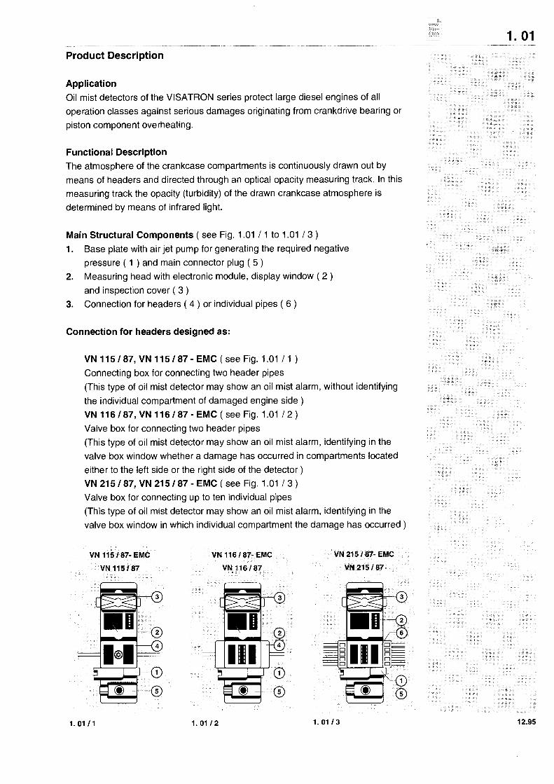
Main Structural Components ( see Fig. 1 .O1 / 1 to 1 .O1 / 3 )
1. Base plate with air jet pump for generating the required negative
pressure ( 1 ) and main connector plug ( 5 )
2. Measuring head with electronic module, display window ( 2 )
and inspection cover ( 3 )
3. Connection for headers ( 4 ) or individual pipes ( 6 )
Connection for headers designed as:
VN l l S l 8 7 , VN l l S I 8 7 - EMC (see Fig. 1.01 / 1 )
Connecting box for connecting two header pipes
(This type of oil mist detector may show an oil mist alarm, without identifying
the individual compartment of damaged engine side )
VN 116187, VN 116187- EMC (see Fig. 1.01 1 2 )
Valve box for connecting two header pipes (This type of oil mist detector may show an oil mist alarm, identifying in the
valve box window whether a damage has occurred in compartments located
either to the left side or the right side of the detector ) VN215/87,VN215/87-EMC(see Fig. 1.01 1 3 )
Valve box for connecting up to ten individual pipes (This type of oil mist detector may show an oil mist alarm, identifying in the
valve box window in which individual compartment the damage has occurred )

Technical Data
Operating voltage: 24 V DC +/- 25%, with reverse battery protection
Power consumption: Maximum 3 A
Electromagnetic
compatibility: Wiring failures:
50 Hz to 10 kHz, 3 V eff. 110 kHz to 50 MHz, 1 V eff.
Electromagnetic fields:
30 kHz to 200 MHz, field strength 10 V / m,
Damped oscillation:
1 MHz,l kV, 400 pulses per second,
High- energy pulses:
0.5 joule, 5 kV, Ri = 500 Q
Electromagnetic fields:
30 kHz to 1 GHz with 10 V/m, Acc. to IEC 801 - 3
( ambient class 3, 10 V / m, 30kHz - 16Hz )
Fast transients ( burst ):
Acc. to IEC 801 - 4, ( ambient class 3 )
Electrostatic discharge:
ACC. to IEC 801 - 2
Load to relay outputs: Maximum 60 V AC / DC, 2 A AC 1 DC, 60 W, 125 VA
Sensitivity: 1st row: switch position, 2nd and 3rd row: required
opacity for triggering an alarm
Switch position:
Alarm level: (% of opacity) of VN 115187- EMC 570 10,O 25,O and VN 115187
Alarm level: (% of opacity) of VN 116187-EMC and VN 116187 5 3 0fVN215187- EMC and VN 215 I 8 7

Technical Data
Negative
pressure measured:
Driving air for air jet pump:
Air consumption:
At least 60 mm, maximum 80 mm W.G.
in Measuring Unit
0.3 to 0.5 bar
Dependent on the number of
suction points, however, max. 1 normal m3 1 h
Protection: IP 44
Admissible operating
temperature range: 0° C bis +70° C
Admissible oil mist
temperaturerange: Maximum +70° C
Admissible storage and
transport temperature range: - 25" C bis +80° C
Humidity: Maximum 90% relative humidity
Vibration: Maximum acceleration 6 g
Dimensions:
Weights:
Pipe connections for
suction system:
( see drawings 1.04 I 1, 1.04 I 2, 1.05 I 1 )
VN l l 5 I 8 7 , V N 115187-EMC7.5 kg
VN l l 6 l 8 7 , V N 116187-EMC9.4 kg
VN 21 5 I 87, VN 21 5 I 87 - EMC 9.6 kg
VN 115187, VN 115187-EMCand
VN 116187, VN 116187- EMC
Header ( two pieces, 0 22 x 2 ( id . 18 mm )
maximum length: 9 m, R 112" and R 314"
VN 215187, VN 215187- EMC
Individual pipes (maximum 10 pieces ),
014 x 2 ( i.d. 1Omm ) maximum length: 9 m


Installation
General
It is important to emphasize cleanliness during the assembly work!
Clean pipelines and fastening parts before assembly.
Lay pipes in a stress- free manner!
Installation position of the device:
Locate the oil mist detector in a vertical position!
Make sure not to install the device within the airflow of blowers or air deflectors.
Suction pipes VN 115 / 87 - EMC and VN 116 / 87 - EMC ( see Fig. 2.1 / 1 )
Material: Seamless steel pipes,
header ( 1 ) 22 x 2 mm ( i.d. 18mm ), max. length: 9 m
suction pipes ( 2 ) 10 x 2 mm ( i.d. not less than 6mm )
Pipe Laying: Ascending to the device,
ascending gradient 2% to 4%, without sagging, avoid oil collection
( see Fig. 2.01 1 1 )

Headers above suction points for:
2.0211
Headers below suction points:
2 .0212
@) Header pipe 022 mm x 2 mm ( i.d. 18mm )
@ Compartment suction pipes to header 010 mm x 2 mm
( id . not less than 6mm )
@) Pipe end- siphon 100 mm with oil return back to the engine,
or 200 mm with oil discharge outside the engine

Suction pipes VN 21 5 1 87 - EMC, VN 21 5 / 87
Material: Seamless steel pipes, 14 mm x 2 mm ( i.d. 10mm )
Pipe Laying: Ascending to the device, ascending gradient 2 - 4% ( see Fig. 2. 03 I 1 )
Lay suction pipes in

Suction funnel in the crankcase compartment
The suction funnels have to be fitted in such a way that flooding by splashing
bearing oil or returning Piston cooling oil is avoided ( see Fig. 2. 04 1 1 ).
Caution: Make sure funnels are not interfering with
rotating or moving parts of the engine.

Installation of siphon blocks
Tightening torque: 30 Nm

0 Connection numbers - .- -".-" ".,*
Closed by * drain plug
Connectio, O sucfion pi,,
n for
Suction piping of VN 21 5 1 87 - EMC
Connecting flange, Valve box
left right
Unused pipe connection bores in flangeare to be plugged
with the supplied viton plugs.

Suction piping of VN 215 I 87 - EMC
Connecting flange, Valve box
left right
Unused pipe connection bores in flangeare to be plugged
with the supplied viton plugs.

No back pressure
and no oil collection
is allowed in
exhaustair pipe!
Parts are not included
in the scope of supply,
but they can be
purchased as an option!
Air supply
@) Discharge funnel
@ Draft air connection set
@ Exhaust air connection
Pressure regulator unit consisting of:
@ Throttle block
@ Pressure connection 2 - 12 bar
@) Pressure regulator
If parts are not included in the scope of supply they can be purchased as an option!
To avoid backpressure, lay exhaust pipes without any reducers (DN 22).
Avoid sagging and oil collection in pipes ( See drawing 2. 08 I 1 )
Electrical connection ( see Fig. 2. 09 I 1 )
Connection: 24 V DC
min. 18 V
max. 30 V
Power consumption: 3 A
Protection: 4 A with semi time- lag
When power is supplied by batteries, charging voltages of more than 30 V
might occur. These voltages are not permitted. Device will go into failure mode.
Voltage limiters must be installed! ( See Fig. 2. 09 / 2 )

Terminal Plan
2.0911
Power supply connection for battery supply


Commissioning
Adjust suction pressure
The suction pressure must be calibrated by adjusting the pressure regulator when
the engine is at a standstill. Make sure ventilation of the engine room is in operation
( pressure difference in room ). An increase or decrease of the pressure
in the crankcase compartment during operation and its effect on the flow velocity
of the oil mist in the suction pipes, is largely compensated by the internal restriction
integrated in the device. (e.g., +25 mm W. G. in the crankcase compartment against
the atmosphere account for an increase of the oil mist flow velocity in the suction
pipes of approx. 8%; +50 mm W. G. of approx. 14%, a negligible figure).
This is important because precipitation of minute oil droplets of the oil mist
increases with a too high flow rate, thus reducing the sensitivity of the device.
Pressure regulator unit I "T--3,
1. Connect U-tube pressure gauge at inspection cover. ( See Fig. 3.02 1 1 )
( Pressure gauge is included in the service box, available as an option )
2. Loosen nut (1) and turn setscrew (2) in clockwise direction gently up to the stop.
3. Open safety cover ( 3 ) at the throttle ( 5 ) and manually turn setscrew ( 4 )
in clockwise direction gently up to the stop.
4. Switch on compressed air supply with inlet pressure ( range 2 to 12 bar ).
The pressure gauge should now read zero pressure.
5. Turn setscrew ( 4 ) in counterclockwise direction until the U- tube
pressure gauge indicates a negative pressure of 80 mm W. G.
6. Close safety cover.
7. Turn setscrew ( 2 ) in counterclockwise direction until the negative pressure
is only 60 mm W. G.
8. Tighten counternut ( 1 ).
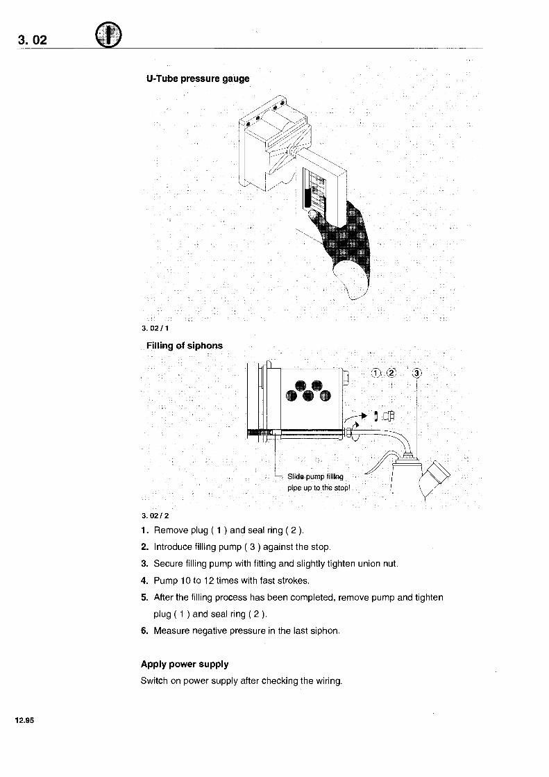
Remove plug ( 1 ) and seal ring ( 2 ).
Introduce filling pump ( 3 ) against the stop.
Secure filling pump with fitting and slightly tighten union nut.
Pump 10 to 12 times with fast strokes.
After the filling process has been completed, remove pump and tighten
plug ( 1 ) and seal ring ( 2 ).
Measure negative pressure in the last siphon.
Apply power supply
Switch on power supply after checking the wiring.

Device Operation
Control and display elements
After the preparation work has been carried out ( commissioning ) the device sets
itself to normal operation in approx. 30 seconds, after the power supply has been
switched on. This phase is indicated by a blinking LED No. 1.
The device only needs to be controlled, if:
- an oil mist alarm is recognized
- a malfunction of the oil mist detector is recognised
- the oil mist detector has to be maintained.
The present state of the device is indicated in the display window:
Visatron Display Window
5
Test -0
4
Alarm Level 1

Display and function during normal operation:
The basic state ( oil mist opacity below alarm level ) is marked by
( see Fig. 3. 03 I 1 ):
- green READY LED is on
- the percentage of change in oil mist opacity with regard to basic opacity is
shown on the opacity display
- TEST LED is off
- ALARM LED is off
- READY relay switched on
- ALARM relay switched off
- RESET button showing no function
- all valves in the valve box are opened, visible by the symbols displayed in the
inspection windows of the valve box
(onlyVN 116187- EMC,VN 116187andVN215187-EMC,VN215/87)
Opacity increase beyond search run level
The search run level is fixed to 10 % of the adjusted alarm level. Valves in the
valve box are activated according to a defined algorithm in order to find the
corresponding engine side or compartment showing an increasing opacity
( search run ). The search run can be interrupted by pressing the RESET button.
Further opacity increase beyond alarm level marked by:
- blinking red ALARM LED
- READY relay is switched on
- ALARM relay is switched on
- 3 red symbols in the inspection window of the valve box showing the
engine side on which the damage has occurred
(onlyVN 116187- EMC, VN 116187)
- a red symbol in the inspection window of the valve box showing the
compartment in which there is the highest opacity.
( only VN 21 51 87- EMC, VN 21 51 87 )
Alarm condition reset to basic state
- By pressing the RESET button
- If there is a device failure, e. g. breakdown of driving air supply
( READY LED is off )
Display and function in case of a failure
A failure is shown by:
- green READY LED switched off
- the LED assigned to the failure is blinking in the opacity display
- TEST LED switched off
- ALARM LED switched off
- READY relay switched off
- ALARM relay switched off
- RESET button toggling from fault indication to opacity display and vice versa
Oil mist opacity exceeds alarm level
- TEST LED is additionally switched on
- READY LED remains switched off
- ALARM LED remains switched off!
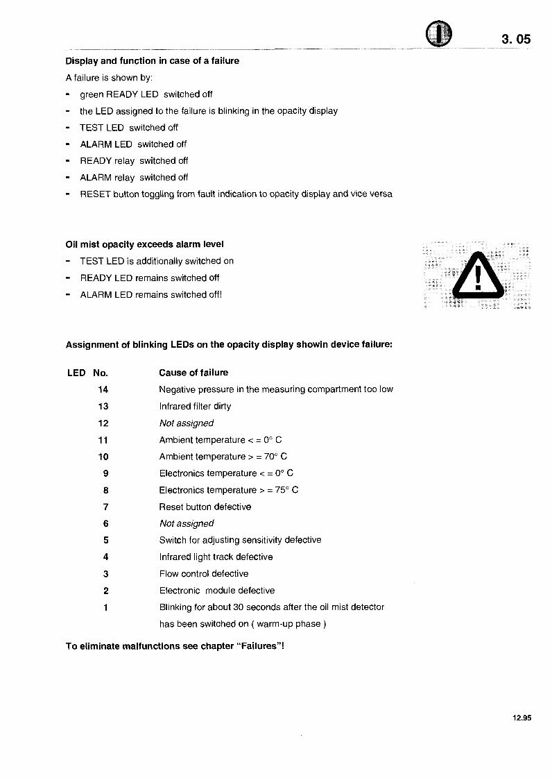
Assignment of blinking LEDs on the opacity display showin device failure:
LED No.
14
13
12
11
10
9
8
7
Cause of failure
Negative pressure in the measuring compartment too low
lnfrared filter dirty
Not assigned
Ambient temperature c = 0" C
Ambient temperature > = 70' C
Electronics temperature c = 0" C
Electronics temperature > = 75" C
Reset button defective
Not assigned
Switch for adjusting sensitivity defective
lnfrared light track defective
Flow control defective
Electronic module defective
Blinking for about 30 seconds after the oil mist detector
has been switched on ( warm-up phase )
To eliminate malfunctions see chapter "Failures"!

ALARM LEVEL Switch
Meaning of switch positions:
1 = Highest sensitivity
4 = Factory-set sensitivity
10 = Lowest sensitivity
To change sensitivity
( this must be done by authorized personnel only! ):
- Pull out plug with RESET button
- Unscrew measuring head casing
- Remove electronic module (see Fig. 6.0211)
- Adjust new sensitivity at ALARM LEVEL switch by means of a screwdriver
- Reinsert electronic module
- Screw on measuring head casing
- Reconnect plug with RESET button

Function of relay outputs
Function of READY relay
( corresponding to the state READY LED )
- The relay is switched on when the oil mist detector is in operation
Function of ALARM relay
The relay is switched on when the opacity exceeds the adjusted alarm level.
Wire break monitoring by the alarm system is made possible by wire break
resistors installed between contacts 7 and 8 as well as between 14 and 16
( 33 kQ factory-preset ).
To replace the line break resistors the electronic module must be removed.
The resistors are located near the relay on the lowest printed electronic board
(R222, R 223).
Attention:
In case of an oil mist alarm, the oil mist detector (OMD) must be in condition
to react within the next few seconds and shut down the engine,
in order to minimise immediate or consequential damages

Performance Test
A Attention
The engine is uncontrolled during this performance test!
A performance test of the device without an alarm being indicated externally
can be carried out as follows:
- Open the cover of the measuring head casing
- Wait until the READY LED is switched off ( after about 10 seconds ) and LED14
is blinking ( negative pressure in the measuring compartment too low )
- Darken the measuring track with filter glass or another object
- Search run ( as described in 3. 04 ) is started
- TEST LED lights up when alarm level is reached
- Alarm reset by pressing the RESET button
- By pressing the RESET button once again the display switches over
from fault indication to opacity display
- Close cover again
- Device is again ready for operation after about 15 seconds
( READY LED is switched on )
Attention
Take care that the cover of the measuring head casing is definitely closed
after the performance test has been carried out in order to ensure that the
engine is controlled again!

When painting works are carried out near the device,
the draft air supply to the device has to be turned off,
in order to prevent the scavenging air filters from clogging.
Shut Down
- Stop driving air supply
- Do not switch off the power supply
Storage
in closed rooms
T min -25°C
T max +80°C
Maximum air humidity 85%


Performance Test 1 Maintenance
Performance test
(To be preformed before the engine is started):
Pull out the main supply plug,
green READY LED will go off
Re- install main supply plug,
LED No. 1 is blinking for about 30 seconds, then:
the green READY LED and LED No. 1 light up.
Device is ready for operation
Open inspection cover at the measuring head.
After about 15 seconds the green READY LED and
LED No. 1 turn off simultaneously.
LED No. 14 is blinking
( meaning: negative pressure in the measuring compartment is too low )
Close inspection cover at the measuring head again.
LED No. 1 is blinking for about 15 seconds.
The green READY LED subsequently switches on.
Device is ready for operation.
Performance test with test vapour, e. g. vapour distillate from the service box
( to be performed only when engine is not running )
- Open crankcase - cover of a compartment in order to access
a suction pipe or sampling funnel.
- Fill the plastic bag ( found in the service box ) with vapour
- Affix the plastic bag to suction pipe or sampling funnel.
- Allow the oil mist detector to draw in the distillate vapour for
a minimum of 20 seconds.
- It depends on the vapour density and suction time ( at least 20 seconds )
1. whether an oil mist alarm is triggered, or
2. whether an oil mist alarm is triggered, and a search run is started, or during
the search run only one half or the engine or the
affected compartment is indicated.
( If the amount of vapour is insufficient or the suction time is too short, a wrong
compartment may be indicated in the display window of the valve box. )
12.95

Maintenance work to be carried out regularly. In case of non-compliance, the
manufacturer's liability expires. Maintenance work has to be documented.
Monthly: Check the negative pressure in the measuring head
( range 60 - 80 mm H20 )
Quarterly: Replace the sintered bronze filter in the measuring head.
Attention: Filters cannot be cleaned.
. ( see Fig. 5. 03 / 1 )
Clean the two fresh air bores in the measuring head
( see Fig. 5. 03 / 2 )
Clean the infrared filter glasses in the measuring head
( see Fig. 5. 04 / 1 )
Every 6 months: ( only with siphon block assembly system,
optional for all OMD device types )
In order to do so:
Remove header pipes from the connecting box,
( V N ll5/87- EMC, VN ll5/87) orfrom thevalve boxof
VN 116 / 87 - EMC, VN 1 1 6 / 87, or individual pipes from
valve box of VN 21 5 / 87 - EMC, VN 21 5 / 87
(to ensure that the device is not contaminated during the
cleaning operation). Remove siphon block plug, blow-clean the
siphons with compressed air (max. 7 bar), mount the header or
the individual suction pipes and siphon block plug,
tighten accordingly.
Subsequently fill the siphon blocks with lubricating oil
( see Fig. 3. 02 / 1 )

Annually: Replace the sintered bronze filter in the pressure reducer
(see Fig. 4. 03 / 1 )
In order to do so:
Turn off control air supply, remove plug ( 1 ) with O- ring ( 2 ),
detach sintered bronze filter (3), insert new filter, install and
tighten plug ( 1 ) with O-ring ( 2 ) and turn on the air supply.

Product Description
Application Oil mist detectors of the VISATRON series protect large diesel engines of all operation classes against serious damages originating from crankdrive bearing or
piston component overheating.
Functional Description The atmosphere of the crankcase compartments is continuously drawn out by
means of headers and directed through an optical opacity measuring track. In this measuring track the opacity (turbidity) of the drawn crankcase atmosphere is
determined by means of infrared light.
Main Structural Components ( see Fig. 1 .O1 / 1 to 1 .O1 / 3 )
1. Base plate with air jet pump for generating the required negative
pressure ( 1 ) and main connector plug ( 5 )
2. Measuring head with electronic module, display window ( 2 )
and inspection cover ( 3 )
3. Connection for headers ( 4 ) or individual pipes ( 6 )
Connection for headers designed as:
VN l l S l 8 7 , VN l l S I 8 7 - EMC (see Fig. 1.01 / 1 )
Connecting box for connecting two header pipes
(This type of oil mist detector may show an oil mist alarm, without identifying
the individual compartment of damaged engine side )
VN 116187, VN 116187- EMC (see Fig. 1.01 1 2 )
Valve box for connecting two header pipes (This type of oil mist detector may show an oil mist alarm, identifying in the
valve box window whether a damage has occurred in compartments located
either to the left side or the right side of the detector ) VN215/87,VN215/87-EMC(see Fig. 1.01 1 3 )
Valve box for connecting up to ten individual pipes (This type of oil mist detector may show an oil mist alarm, identifying in the
valve box window in which individual compartment the damage has occurred )

Technical Data
Operating voltage: 24 V DC +/- 25%, with reverse battery protection
Power consumption: Maximum 3 A
Electromagnetic
compatibility: Wiring failures:
50 Hz to 10 kHz, 3 V eff. 110 kHz to 50 MHz, 1 V eff.
Electromagnetic fields:
30 kHz to 200 MHz, field strength 10 V / m,
Damped oscillation:
1 MHz,l kV, 400 pulses per second,
High- energy pulses:
0.5 joule, 5 kV, Ri = 500 Q
Electromagnetic fields:
30 kHz to 1 GHz with 10 V/m, Acc. to IEC 801 - 3
( ambient class 3, 10 V / m, 30kHz - 16Hz )
Fast transients ( burst ):
Acc. to IEC 801 - 4, ( ambient class 3 )
Electrostatic discharge:
ACC. to IEC 801 - 2
Load to relay outputs: Maximum 60 V AC / DC, 2 A AC 1 DC, 60 W, 125 VA
Sensitivity: 1st row: switch position, 2nd and 3rd row: required
opacity for triggering an alarm
Switch position:
Alarm level: (% of opacity) of VN 115187- EMC 570 10,O 25,O and VN 115187
Alarm level: (% of opacity) of VN 116187-EMC and VN 116187 5 3 0fVN215187- EMC and VN 215 I 8 7

Technical Data
Negative
pressure measured:
Driving air for air jet pump:
Air consumption:
At least 60 mm, maximum 80 mm W.G.
in Measuring Unit
0.3 to 0.5 bar
Dependent on the number of
suction points, however, max. 1 normal m3 1 h
Protection: IP 44
Admissible operating
temperature range: 0° C bis +70° C
Admissible oil mist
temperaturerange: Maximum +70° C
Admissible storage and
transport temperature range: - 25" C bis +80° C
Humidity: Maximum 90% relative humidity
Vibration: Maximum acceleration 6 g
Dimensions:
Weights:
Pipe connections for
suction system:
( see drawings 1.04 I 1, 1.04 I 2, 1.05 I 1 )
VN l l 5 I 8 7 , V N 115187-EMC7.5 kg
VN l l 6 l 8 7 , V N 116187-EMC9.4 kg
VN 21 5 I 87, VN 21 5 I 87 - EMC 9.6 kg
VN 115187, VN 115187-EMCand
VN 116187, VN 116187- EMC
Header ( two pieces, 0 22 x 2 ( id . 18 mm )
maximum length: 9 m, R 112" and R 314"
VN 215187, VN 215187- EMC
Individual pipes (maximum 10 pieces ),
014 x 2 ( i.d. 1Omm ) maximum length: 9 m


Malfunctions
Failures and corrective action
A malfunction in the operation of the oil mist detector has occurred if:
- the green READY LED is off
- an LED assigned to the failure mode is blinking in the opacity display
A pending oil mist alarm is reset.
Failure:
No display in the inspection window, all LEDs off
Possible cause:
Breakdown of power supply
or voltage too low
Fuse in the measuring head
defective ( see F i g 5 06 / 1 )
Should there still be no indication
Remedy:
Check power supply
by: pulling off the main supply plug.
Between terminals 1 and 2 in the socket
on the base plate, check if 18V to 30V
is available.
Push on main plug and lock into place.
Make sure that the power supply does not
break down under the load of the
oil mist detector. ( voltage not below 18V )
Replace fuse in the measuring head
( 2 A, semi time lag )
by: pulling off the main supply plug.
Detach measuring head ( 8 screws )
Replace fuse by a new one.
Mount measuring head into position.
Push on main supply plug
and lock into place.
Replace the electronic module
( see Fig. 6. 02 1 1 )

Failure
LED No. 14 is blinking - negative pressure in the measuring head too low.
Possible causes: Remedy:
Open inspection cover Close inspection cover
Filter or water separator in the Clean accordingly, empty if necessary
air supply pipe clogged or filled
Pressure reducer misadjusted Readjust ( see chapter 3. 01 )
by vibration
Pressure restrictor misadjusted Readjust ( see chapter 3. 01 )
by vibration
Sintered bronze filter in the Replace bronze filter
pressure reducer clogged ( see Fig. 5. 03 / 1 )
by: Turn off the control air supply.
Release plug ( 1 ),
remove 0 - ring ( 2 ),
detach filter ( 3 ),
insert new filter ( 3 ),
mount 0- ring ( 2 ),
install and tighten plug ( 1 ),
Turn on air supply.
Sintered bronze filters in the Replace sintered bronze filters
measuring head clogged ( see Fig. 5. 03 / 1 )
by: opening the inspection cover.
Remove circlips.
Mount new filters ( always on both sides,
rough side outwards),
insert circlips,
close cover.

Possible causes: Remedy:
Fresh air bores for
flow control clogged
Leakage at the device
Clean both bores ( see F i g 5 03 / 2 )
by: opening the inspection cover.
Press cleaning pin contained in the
service box into the left or right fresh air
bore, respectively,
The bores can be seen from the side
of the scavenging air chamber.
Close inspection cover.
Check all pipes and seals
by: checking flexible expansion bellows
( accessible after the measuring head
has been dertached )
Replace damaged seals or
expansion bellows.
Exhaust air pipe malfunction Eliminate blockage of the exhaust air pipe,
the air must flow without restriction.

Failure
LED No. 13 is blinking - infrared filter clogged -
Possible causes: Remedy: ( see Fig. 5. 04 / 1 )
Infrared filter clogged Clean infrared filter
by: opening the inspection cover.
t Soak cotton stick (plastic only!) with alcohol.
Clean infrared filter with
cotton stick several times.
Rub infrared filter dry by means of
cotton stick. Make sure no fluff remains on
the infrared filter
Close inspection cover again.
If failure continues: Replace electronic module
( see Fig. 6. 02 / 1 )
Failure:
LED No. 11 is blinking - ambient temperature below 0" C
Possible causes: Remedy:
Engine compartment ventilator Change blowing direction of ventilator,
blows cold air onto the device. away from oil mist detector.
Failure:
LED No. 10 is blinking - ambient temperature above 70" C
Possible causes: Remedy:
Source of heat radiates Protect device against sources of heat
on the device. radiation, ensure an improved fresh air

Failure
LED No. 9 is blinking - electronic temperature below 0" C
Possible causes: Remedy:
Engine room ventilator blows Change blowing direction of the ventilator to
cold air onto the device. ensure that cold air it is not directed to the oil
mist detector
Failure
LED No. 8 is blinking - electronic temperature above 70" C
Possible causes: Remedy:
Source of heat radiates Protect device against sources of heat
on the device. radiation, improve fresh air circulation.
Failure
LED No. 7 is blinking - RESET button defective
Possible causes: Remedy:
Blocked RESET button Eliminate blocking
Failure
LED No. 5 is blinking - OMD sensitivity switch defective
Possible causes: Remedy:
Switch defective Replace electronic module
( see Fig. 6. 02 / 1 )
Failure
LED No. 4 is blinking - infrared light track defective
Possible causes:
Infrared filter clogged
Remedy:
Clean infrared filter ( see failure LED No. 13 )
If failure continues Replace electronic module ( see Fig. 6. 02 / 1 )
Failure
LEDs No. 3 or 2 are blinking
Possible causes: Remedy:
Electronic module defective Replace electronic module ( see Fig. 6. 02 / 1 )


Repairing
Replace electronic module / measuring head
Attention
If these factory pre- settings (resistors) are replaced by those with other values,
it must be ensured that a spare electronic module or the one in a
replacement measuring head is also modified accordingly!
Modifications have to be printed on the protecting cover plate on the rear side of the
measuring head casing, in the fields provided for this purpose.
( see Fig. 6. 01 I 1 )
Type VN 115187-
Serial No.
VN 116187 1
Oilmist - detector mounted on Main engine I I I I l u x . engine- I I
Display Panel
Adjustment by manufacturer:
Alarm Level ( swlch S1 )Poatlon - Resistor between alarm contact 7 8 k Ohm Resistor between alarm contact 15 16 k Ohm Mode (swlch 52 Optlon ) Postion - Altered adjustment tw H I V:
Alarm Level j swch S1 IPosltlon - Resstor between alarm contact 7 . 8 - k Ohm ~ e s i ~ t o r between alarm contact 15 16 - k Ohm Mode ( swlch 52 Optlon ) Postion
For rnanutacturer Only Lower
The wire break resistors are located on the first visible printed circuit board,
which is under the protecting cover plate, near the relays (R 222 and R 223)!
The resistors are designed as plug- in resistors and can be replaced
without soldering!
You find the ALARM LEVEL switch on the front display plate of the
electronic module ( see Fig. 3. 03 I 1 ).

Procedure: ( see Fig. 6. 02 1 1 )
- Pull off the main supply plug
- Dismantle the measuring head ( 8 screws )
If the electronic module is replaced or needs to be modified:
- Remove protecting cover plate ( 3 screws )
- Remove the 3 hexagon distance bolts
- Remove defective electronic module from the casing, first pulling off the
lateral flat cable plug from the socket in the casing.
- Mount new electronic module in reverse order
- Install protecting cover plate, fasten 3 screws
- Fasten measuring head, tighten 8 screws moderately.
- Push on main supply plug and lock it into place
- Carry out performance test ( see chapter 4.01 )
@ Dismantle cover plate by removing 3 screws
@ Loosen 3 hexagonal screws of module
@ Extract module
Attention:
The electronic module is equipped with components which are sensitive
against electrostatic discharges. A replacement must be carried out by
skilled personnel only! Do not touch infrared lenses or circuitry! Utilise
grounding strap on your wrist.

Leaks or failure of the valve box of VN 115 / 87 - EMC, VN 11 5 / 87
Remedy: ( see Fig. 6.03 I 1 )
Disconnect header pipes on the left and right side of connecting box ( 1 ),
push pipes aside to get free access.
Loosen the two screws ( 2 ) and ( 3 ) of the connecting box
Detach the connecting box and remove the gasket On principle, use new
Check if bores 1, 2 and 3 are free from dirt, blow them free with connecting box gasget!
compressed air
Clean the base plate cavity from oil.
Assembly in reverse order, utilising new gasket.
Leaks or failure of the valve box of VN 116 / 87 - EMC, VN 116 / 87
Remedy: ( see Fig. 6.04 I 1 )
Dismantle the pipe connecting blocks with the headers on the
right and left side
Push away the header pipes for free access to the valve box
Unscrew the valve control cable plug and loosen the four screws
( 3 ), ( 4 ), (5 ) und ( 6 ) of the valve box.
Detach valve box and remove seal
Check if bores 1, 2 and 3 are free from dirt, blow them free
with compressed air.
Clean the base plate cavity from oil.
Assembly in reverse order, utilising new seals and gasket

On principle, use new
valve box seals and
gasket!
Leak or failure of the valve box of VN 215 / 87 - EMC, VN 215 / 87
Remedy: ( see Fig.. 6. 04 I 2 )
Release the pipe connecting blocks ( 1 ) und ( 2 )
on the right and on the left side.
Push away blocks with with individual suction pipes for free access
to the valve box.
Unscrew valve control cable plug and loosen screws (3), (4), (5) und (6)
of the valve box
Detach valve box and remove seal
Check if bores 1, 2 and 3 are free from dirt, blow them free with
compressed air.
Clean the base plate cavity from oil.
Assembly in reverse order, on principle, use new valve box seals and gasket.

False alarm in the case of fire with smoke development in the engine room
In case of a fire with smoke development in the engine room, a false alarm cannot
be prevented since smoke may pass into the measuring track through the sintered
bronze filters in the measuring head. This condition induces an opacity which can
trigger an oil mist alarm.
Remedy: Install optional pressurised air scavenging system, available from the
manufacturer ( Press RESET button to reset the alarm )
Further possible failures
Sudden false alarms in very warm or cold climatic areas can be triggered by
humidity ( in the crankcase ) falling below the dew point:
water droplets passing the measuring track or dew on the filter glasses may trigger
a false alarm.
Remedy: Check negative pressure and calibrate to 60 mm W. G., if required.
Ventilation air fans, if any, blowing towards the device and
its suction pipes.
Change blowing direction ( install deflectors ) of the ventilator to ensure
that cold air it is not directed to the oil mist detector or suction pipes.
Check VISATRON heating system. ( The heating element is located in
the base plate and is hooked up with the connector plug
to the 24 V power supply!)
Furthermore, a measuring head heating system is available as an option
(see chapter "Options"!).


Spare Parts
7.01 11
VN l l 5 / 8 7 - EMC
VN 115/87
VN 215/87 - EMC

Item Description
VN 115/87
Article No. No. of pieces
1. Connecting casing 10202
2. Heating element 10051
3. Cable clip 10052
4. Lower VN part 10032
5. Seal 10206
6. Connecting socket 10033
7. Valve box seal 10049
8. Measuring head suspension, bottom 1001 9
9. Cap seal 10054
10. Screw plug R 114" 10083
11. Cover for measuring head ' 10088
12. Scavenging air filter 10042
13. Circlip for scavenging air filter 1 0041
Valve box VN 1 16 / 87
Heating element
Cable clip
Base plate
Oil reflux seal
Connecting socket
Oil mist seal
Seal for valve box
Measuring head suspension, bottom
Screw plug R 114"
Seal for ltem 10
Cover for measuring head
Scavenging air filter
Circlip for scavenging air filter
Measuring head VN 11 6 / 87
Valve box VN 21 5 / 87
Heating element
Base plate
Cable clip
Oil reflux seal
Connecting socket
Oil mist seal
Valve box seal
Measuring head suspension, bottom
Clamping plate for pipe connection
Screw plug R 114"
Seal for ltem 11
Cover for measuring head
Pipe connection, left
Scavenging air filter
ltem
14.
15.
16.
17.
18.
19.
24.
25.
26.
27.
28.
Description Article No. No. of pieces
Measuring head for VN 1 15/87
Expansion bellows
Measuring head suspension, top
Measuring head seal
Srew plug R 112"
Screw plug seal
Protecting cover for E-module
Fastening screw for E-module
Electronic module for VN 11 51 87
Fuse 2 A
Fuse cap
Expansion bellows
Measuring head suspension, top
Measuring head seal
Screw plug R 112"
Seal for ltem 19
Pipe connection
Seal for connecting casing
Protecting cover for E-module
Fastening screw for E-module
Electronic module VN 1 161 87
Fuse 2A
Fuse cap
Circlip for scavenging air filter
Measuring head for VN 215 / 87
Expansion bellows
Measuring head suspension, top
Measuring head seal
Pipe connection, right
Drain plug for pipe connection
Rubber sleeve for pipe connect.
Protecting cover for E-module
Fastening screw for E-module
Electronic module for VN 2151 87
Fuse 2A
Fuse cap

Item Description Article No.
VN l l 5 / 8 7 - EMC
Connecting casing
Heating element
Cable clip
Lower VN part
Seal
Connecting socket
Valve box seal
Measuring head suspension, bottom
Cap seal
Screw plug R 114"
Cover for measuring head
Scavenging air filter
Circlip for scavenging air filter
VN 116 /87 - EMC
Valve box VN 11 6 I 87 - EMC
Heating element
Cable clip
Base plate
Oil reflux seal
Connecting socket
011 mist seal
Seal for valve box
Measuring head suspension, bottom
Screw plug R 114"
Seal for ltem 10
Cover for measuring head
Scavenging air filter
Circlip for scavenging air filter
Measuring head VN 11 6 I 87- EMC
VN 2 1 5 / 8 7 - EMC
Valve box VN 215 187 - EMC
Heating element
Base plate
Cable clip
Oil reflux seal
Connecting socket
011 mlst seal
Valve box seal
Measuring head suspension, bottom
Clamping plate for pipe connection
Screw plug R 114"
Seal for ltem 11
Cover for measuring head
Pipe connection, left
No. of
pieces
1
1
1
1
1
1
1
2
2
1
1
2
2
1
1
1
1
1
1
1
1
2
1
2
1
2 i
2
1
1
1
1
1
1
1
1
1
2
2
1
2
1
1
Scavenging air filter 10042 2
ltem
14.
15.
16.
17.
18.
19.
24.
25.
26.
27.
28.
Description Article No.
Measuring head for VN 11518 -EMC 10601
Expansion bellows 10023
Measuring head suspension, top 1001 8
Measuring head seal 10698
Srew plug R 112" 10208
Screw plug seal 10209
Protecting cover for E-module 10084
Fastening screw for E-module 10085
Electronic module, VN 1 151 87-EMC 10603
Fuse 2 A 10043
Fuse cap 10087
Expansion bellows 10023
Measuring head suspension, top 1001 8
Measuring head seal 10698
Screw plug R 112" 10208
Seal for Item 19 10209
Pipe connection 1 031 2
Seal for connecting caslng 1 031 3
Protecting cover for E-module 10084
Fastening screw for E-module 10085
Electronic module VN 11 61 87- EMC 10707
Fuse 2A 1 0043
Fuse cap 10087
Circlip for scavenging air filter
Measuring head,VN 215 I 87- EMC
Expansion bellows
Measuring head suspension, top
Measuring head seal
Pipe connection, right
Drain plug for pipe connection
Rubber sleeve for pipe connect.
Protecting cover for E-module
Fastening screw for E-module
Electronic module VN 21 51 87- EMC
Fuse 2A
Fuse cap
7. 03 No. of
pieces
1
2
2
1
3
3
1
3
1
1
1

Service - Box

Designation
Manual in English
Quick connecting for U- tube manometer
Gasket
Wrench mounting of electronic module
Filter for pressure reducer
"Upper" spring for elastic mounting of the measuring head
"Upper" distance bolt for elastic mounting of the measuring head
Flexible clamp ring for distance bolts for mounting of the measuring head
"Lower" spring for elastic mounting of the measuring head
"Lower" distance bolt for elastic mounting of the measuring head
Oil return gasket VN 115 187 - EMC, VN 11 5 187
Bottle with alcohol
Cleaning needle
Cottonstick for cleaning of infrared filters
Bottle with slacked water
Screwdriver for mounting of measuring head
Screwdriver for adjustment of alarmborder
Coloured glas, 5%
Safety ring for fresh air filter
Fresh air filter
Flexible bellow for connection of measuring head with base plate
Fuse 2A 1 semi time- lag
Oil return gasket VN 11 6 187 - EMC, VN 11 6 187
Hexagon wrench for valve box mounting
Oil mist gasket valve box VN 116 1 87 - EMC, VN 11 6 1 87, and
VN 21 5 1 87 - EMC and VN 21 5 1 87
Lockplug for not connected tube at VN 215 187- EMC and VN 215 187
Rubberplate for tube connection at VN 21 5 1 87- EMC, VN 21 5 1 87
Mouth piece for cigarette burner
Ring box end wrench
Hexagon wrench for release of lockscrew at cover of measuring head
Screwdriver 4 mm
Pliers for mounting of safety rings for fresh air filters
Gasket for valve 1 box connecting frame
Plastic bag for cigarette smoke
Clamp plate for tube connection at VN 2
U- tube manometer
1 connecting cover
15 187- EMC, VN 215 I 87


VISATRON - Service Facility Adresses
Australia CJA Marine Technology Division of C. Johow & Assoc. PTY. LTD. Unit 3 136 Cochranes Road Moorabbin- Victoria 31 89 Phone-no.: ++61 - 3 - 95 32 13 86 Telefax-no.: ++61 - 3 - 95 32 14 13
Brazil Teletronic Equipamentos Eletronics Ltda. Av. Venezuela, 3- salas 602- 03- 04 CEP 20081 Rio de Janeiro, R. J. Phone-no.: ++55 - 21 - 2 53 60 07 Telefax- no.: ++55 - 21 - 5 16 16 29
Croatia Lemaar Co. Bosnaska 4 21 000 Split Phone-no.: ++385 - 58 - 4 18 01 Telefax- no.: ++385 - 58 - 4 18 01
Denmark J. Klitso A/ S Hirsemarken 1 3520 Farum Phone-no.: ++45 - 44 - 99 70 00 Telefax- no.: ++45 - 44 - 99 70 10 Telex-no.: 3 33 10
Germany Claus- D. Christophel Automations- und Elektrotechnik GmbH Georgswerder Bogen 7 21 109 Hamburg Phone-no.: ++49 - 40 - 75 49 66 0 Telefax- no.: ++49 - 40 - 75 49 66 24
Flnland Schaller Automation lndustrielle Automationstechnik KG lndustriering 14
66440 Blieskastel Germany Phone-no.: ++49 - 68 42 / 508 - 0 Telefax-no.: ++49 - 68 42 / 508 - 260 Telex-no.: 44 685
France Sofraret 48, Rue de Rome 75008 Paris Phone-no.: ++33 - 1 - 45 22 40 84
Telefax-no.: ++33 - 1 - 42 94 99 01 Telex-no.: 280 430
Greece Th. Mantanovitch S. A. 5 - 7 Aghiou Nicolaou Street 18537 Piraeus Phone-no.: ++3O - 1 - 4 51 38 68 Telefax Nr.: ++30 - 1 - 4 13 69 49 Telex-no.: 21 17 71
Hong Kong Hua Xing Equipment Ltd. 1 11 F Hong Kong Computer Centre, 54 - 62 Lockhart Road Wanchai, Hong Kong Phone-no.: ++852 - 8 65 68 03 Telefax-no.: ++852 - 8 61 14 70 Telex-no.: 6 53 97
Italy International Marine Equipment and Services Ing. A. Cacciottoli Sas Via Cassa di Risparmio 6 341 21 Trieste Phone-no.: ++39 - 40 - 66 05 50
Telefax-no.: ++39 - 40 - 66 06 20
Telex-no.: 46 02 09

Japan Nippon Vulkan Co. Ltd. Nikko Building, 2nd Floor 3- 372 Miyahara- Cho, Omiya
Saitama- PFT, Japan 330
Phone-no.: +t81 - 48 - 6 54 48 11
Telefax-no.: ++81 - 48 - 6 54 48 10
Korea BUM- A Trading Co. Ltd.
Hongsun Building, 166- 5
Samsung- Dong Kangnam- Ku
Seoul
Phone-no.: ++82 - 2 - 5 66 33 40
Telefax-no.: t t 8 2 - 2 - 5 65 00 64
Benelux Van Stigt B. V.
Avelingen- West 30
4202 MS Gorinchem Phone-no.: ++31 - 183 - 63 29 06
Telefax-no.: t+31 - 183 - 63 10 66
Norway Maxeta A/ S Porsgrunnsveien 225
3901 Porsgrunn
Phone-no.: ++47 - 35 - 59 77 55
Telefax-no.: t t 4 7 - 35 - 59 79 40
Poland P.P.H. Gdanpol Al. Niepodleglosci 739 A 80967 Sopot 1
Phone-no.: ++48 - 58 - 51 72 41
Telefax-no.: +t48 - 58 - 51 08 55
Singapore 2262
Bond lnstrumentation (Singapore) Pte. Ltd. 8 Gul Street 3
Singapore 629265
Phone-no.: ++65 - 8 61 42 79
Telefax-no.: ++65 - 8 62 40 62
Telex-no.: 5 06 50
Spain Guillermo F. Mallet S.A.
Boix Y Morer, 6
28003 Madrid Phone-no.: t+34 - 1 - 5 54 91 05
Telefax-no.: t+34 - 1 - 5 34 01 82
Bygap S.L. Rambla de Montserrat, 21
08290 Cerdanyola (Barcelona) Phone-no.: t+34 - 3 - 5 80 94 44
Telefax-no.: ++34 - 3 - 5 80 98 20
USA Diesel Monitoring Systems Inc.
4900 Mill Street
Building A-4
Reno, Nevada 8951 1
Phone-no.: t t 1 - 7 0 2 - 8 2 6 2 0 0 3
Telefax-no.: t t 1 - 7 02 - 8 26 20 04
United Kingdom Bond lnstrumentation
& Process Control Ltd.
Drakes Lane, Industrial Estate
Boreham1 Chelmsford
Essex CM3 3BE Phone-no.: +t44 - 2 45 - 36 01 91
Telefax-no.: t t 4 4 - 2 45 - 36 22 48
Telex-no.: 99 51 15


Brochures, Leaflets, etc.

VISATRON
I lo INFO
- PRINT NR. 180003
S C A L E R
OIL MIST DETECTORS SHORT FORM CATALOGUE
SYSTEMS FOR DIESEL ENGINE MONITORING

SCHALLER VISATRON OIL MIST DETECTORS PROTECT EACH DIESEL ENGINE TYPE IN MARINE STATIONARY MOBILE OPERATION
SHOWN BELOWARE THE POSSIBILITIES OF APPLYING THE VARIOUSVISATRON DETECTORSAND SUCTION SYSTEMS
The VISATROh 0 M st Detectors o'me Iypes VN 115 an0 VN 116 Jse a rleaaer-S~ct on-Lee Sysgm uhlch comb nes crank- case compamnenls for M c J a t ng !he crandcase almosphere wnereas 'ne Vt4 215 lype uses a Sing e-S~ctlon.Tuue Srjlem for Ind~vidual companment rnonltonng. Should t be ~mposs~ble to make use of the assembly arrangements shown below, a mod~fied mountlng verslon mlght posslbly be provldsd for upon request at our works
F?
S.08. SPEED Tho-STROKE CROSSMEAD D ESE- ENG [UES na$e relal ve large crankcase in, .nes comoared lo lhose of meo Lrn an0 n yh speea trmn paon englnes - i c novoLa crancase com parlnenls are genwa y mpervloJs y pallroneo and nerelo'e p n o l mot On w no1 CaLSe an, aooreclaoe f ON 0' Cralcase alrno sphere between the &m&&ents as is the case far trunk-piston engines. Only a m y slow build-up d oil mist occurs within the individual compariments unless damage is occurring. Therefor the highly sensetive VISATRON 216 using a SinqleSuctionTube System is ideally suited to monitoring slow speed crosshead engines.
115 Basic model, wlthout damage locallzatlon capabllry
N P E
VN 116 More sendt~ve model, H~ghly senstlve model, capable d indlcaUng the group permitting dlrect lndi- of crankcase compartments where cation d the damaged the damage has occurred crankcase compartment
headersuetion.tube s&lon left
Idw-sudion-tube header.suctionmt'- h-*-'~""lion-tube rnax. 5 single ma. 5 single- sectian right section left tion right suction-tubes left I suctian.tub@?. right
- I I I
a
m.
L I V MEDIUM AND HIGH SPEED TRUNK Header SuctionTube System su~table Sin lasuct~on-Tube S m appltcabie PISTON DIESEL ENGINES, IN LINE for all med~um and hlgh speed diesel to :I medfum and d&?speed dwwl AND V FORM VERSIONS englnes, Wpeclally regarding englne englnes where in case d damage a have aenerallv, unoartitloned oomwari confiauratlons where the crankcase vmform soreadlna of the ort mbst met%-and the mlsl formed in oase d sectlins are essentially unpamioned. throcgh thb whole"crankcase will take damage is therefore rap~dly spread The header tube connections for both more than 15 seconds (crankcase not through the entire crankcase For hot the VN 115 and VN 116 devrces are ent~rely open throughoui the length). spot tocallzaUon by the VISATRON types compatible In case that a higher sensitl- Spewally suhd to large med~um speed VN 116 and VN 215, spread~ng dthe 011 vlty 1s required, the type VN 115 can ea- engines where the removal of several mlst through the whde orankcase shall sdy be replaced by the VN 116 lnspectlon doors d crankcase cornpart. take more than approx 15 seo and 10 rnents when searching for the trouble sec , respectwely may be irksome.

INSTRUMENTS AND SPARE PARTS I VlSATRON OIL MIST DETECTORS
- SCHALLER AUTOMATON lndueerielle Autometlonstechnik KG I n d u s t z r i a r i n g .
OUTLINE DR
PART LIST
INSTRUMENTS
VISATRON VN 115 011 Mlst Detector VN 115
mi 2 Manuals ~n Engllsh Art No 10200 Manual ~n German Art No 10025
TECHNICAL FEATURES IN BRIEF
Manual ln Engllsn Art No 10024
SPARE PARTS FOR LONG VOYAGE EleCVon~c Module Art No 10203 to ~nstall in the measuring unlt
ALTERNATIVELY Compl Measuring Und VN 115 Art No 10201 Set d Small Spare Parts Art No 10056 kdentim for VN 11511181215) s t of Replaceroent Parts Art No 10059 (tdentloal fw VN 11511181215)
OPTIONS Pre~ure Reducer Art No 10001 (idemical for VN 1151116/215) Analog Opaclty Display Art No 1W57 (96xs6 built-In instrument, ldentlcal for VN 11511161215) Pmfmlng 0- An Ns 10015
ACCESSORIES S~NICB BDY An No 10055 hdernical for VN 115/116/215)
I E M INSTRUMENTS
2 01 VISATRON VN 116 Oil Mlst Detedor VN 116
lncl 2 Manuals ln EnglM Art No 10300 2 02 Manual in German Aci No 10025 2 03 Manual In English Art No 10024
SPARE PARTS FOR LONG VOYAGE 2 04 Elsdroruc Module Art No 10203
lo m a l l in the Measurmo Unit - like Item 1.04, as emergency spare part (funMion a$ VN 115)
ALTERNATIVELY 2.05. Compl. Measuring Unit VN 116
oom ridng Electronic Box VN 110 Art. NO. 10301 and h e Box Art. No. 10302
2.06. Set d Small Spare Pam Art. No. 1W56 2.07. Set of Replacement Pam An. No. 10059
OPTIONS 2.08. Pressure Reducer Art. No. 10001 2.09. Analog Opaciv Oiaplay Art No. 10057 2.10. Protectihg Cover Art. No. 10015
ACCESSORIES 2.11. Service Bax Art. Na. 10055
ITEM INSTRUMENTS
3 01 VISATRON VN 215 01 Msi Detector VN 235
lncl. 2 Manuals in Erlglsh Art No 10400 3 02 Manual m German Art No 10025 303 Manual ln Engltsh Art No 10024
SPARE PARTS FOR LONG VOYAGE 3 04 Eldctmnio Module Art No 10203
to lmtall in the Measurmg Und, l~ke Item 1.04, as emergenw spare pan (funmon ss VN 115)
ALTERNATIVELY 3 05 CompL Measurmg Unlt VN 215
mrnpnslng Eiectronro Box VN 215 Art No 10401 and Valve Box Art No 10402
3 06 Set of Small Spere Parts Art No 10036 3 07 Set of Replacement Parts Art No 10059
OPTIONS 3 08 PreSsure Reducer 3a9 Analog Opaody D~splay 8 l o Prowing Cwer
Alt No 10001 ... Art No. 10057 Art No. 10015 P
.
... . . -
valve bm
pfotedvlg wver (optional)
ACCESSORIES 3 11 S e ~ c e Box Art No. 10055 I "


TECHNICAL FEATURES IN BRIEF
ISATRON OIL MIST DETECTORS
tubs connector box threaded to169 Iite
cable for PTC heating inthe ham plate (auotdams of condensation water)
OUTLINE DRAWING I

TECHNICAL FEATURES IN BRIEF
ISATRON OIL MIST DETECTORS OUTLINE DRAWING

608- Fax: 1066421 608260 Telex: 44 885 Airport, SaearbrUckan
SUCTION SYSTEM
SENSITIVITY
I
IPF 'LY I SIGN 3 AND I

For ovar 30 yest8
- SCHALLm AUTOMATlON ' lndustrielie Automet ianstechnik KG- Indust;l
VISATRON OIL MIST DETECTORS MEET THE 3 FOLLOWING BASIC MAIN REQUIREMENTS HIGHEST POSSIBLE SENSlTlVlM to smallest auantaies of oil mlst - so that damaae can be detected while in Droaress
50 mg of sdspended oil per iter of air represents the lower limt for an explosive mixture (LEL- Lo. w Explosion Limt at an ignition ternperaNre of 500 ' C). The sensit;ve VISATRON Oil Mist Detec tors respond at a wncentration of less than 0.2 mgll, i. a 0.4% LEL.
I SHORTEST RESPONSE TIME -to oermit automatic stoodno of the enaine or reduction of ermine smed wi1n.n a lew seconds after me oil mist con.cenlraton has .ncreSed owina to the overheating I of enaine Darts
I In a test with a 6 cylinder in-line medium speed dlesel engine developing about S W O HP, a slight deformation of a ofston was used to induce oiston seizure. The resuit of the test after three hours: drop in engine speed (initlaton of semre): 2d seconos after tne commencement of the drop: detec- I tion d oil mist 'ncrease bv the VISATRON Detector: after a funher 4 seconds: shutdwn order from the oil mist debmor: 36 &on& after commencement ofthe drop in engine speed: manual stopping I of enaine because d considerable anomalus running noisa Inspection of the enaine revealed that one t;oYt had already been torn from the connecting-rid bmmg and that other bok were stretched. It would only have been a matter of seconds until the bearing had failed completely.
Every VISATRON Detector, Types VN 115/116/2l5, wuld in this provoked case of damage have per- mitted the engine to be stopped automatically and in tlma alkr a maximum d 24 seconds, thus pre- venting a mre consequential damage
EXTENSIVE MEASURES FOR ELIMINATION OF FALSE ALARMS - as an alarm prw~ded bv an unreliable device is likelv to be dimarded bv the shids oermnel when the stualion reallv be- wmea secious.
It ooes without w ino that safetv devices like oil mist detectors must be of a hiah aualitv desion I an; also be adapied-to the severe condmons experienced in shipboard operati$. ~unhirmor< must be ensured that environmental influences, as for examole contamration and violent vibrations. will not affect the safe action of the equipmems
An electronic self-balannng measuring system to maintain the sensltiv'ty at a constant value, scaven- ging all chamber for the optics, an antivibration suspension system, and quality assurance dunng pro duct~on are some of the major measures permitting to achim a high reliability of the ViSATRON De- tedars whh regard to failures and false alarms
Another imwrtant aoint is thatlhe VISATRON Detectors whioh werate seleotivelv in accordance with I an terati~n'~rocedure must provide reliable lndicaflon of the damaged compartrient - as otherwise. when no defect is found in the indicated wmoartment (such f a b indications mav owur wth linear
I Scanning Systems), the uncorrected malfunction will muse serious damage wh& the englne is put back into operation.

our wmpany has speciaiised in providing elentronic Our long experience in deveiopment and practical monitoring and control equipment f ~ r automation applination of sensorj as wdl as heavy-dutyelectm- projects as well as in the field of process monitoring, nic devioes lor the most severe environmental wn- We offer an exiemive range of up-to.date hardware diions has resulted in the VlSATRON series d low and software for industrial use. maintenanca Oil Mist Detection Systems for use
on ail types d higher output marine and stationary Diesel enginas.
our wmpany has also been busily engaged in the field of Diesel E n s n s Crankase Monitoring.
VISATRON OIL MlST DETECTORS FULFIL FURTHER I M P O R T A N T R E Q U I R E M E N T S NO COMM SSiONlhG for ad,ustmont when p,l ntooperatlon an0 no resen ng of the eqdpment du- r ng opera on - l h ~ s avo~dlng ado11 ona cost ar s ng from me Lse ol expens ve o&de spec a 61s along w~th eliminat~ng the possib~l~ty of undetected, erroneous settlng
VERY LOW MAINTENANCE REQUIREMENTS (BREAK DOWN SERVICE). Mostly after months of malntenancefree operatlon, a slgnal announces that an uncomplicated and quickly-executed main-
tenance operatlon has become necessary. Thus the main cause for instrument malfunct~on IS ell- minated.
SIMPLE INSTALLATION on the engine - eliminating the possibility of incorrect mounting and the resulting unsatisfactory functioning of the equipment; and the installation costs themselves are reduced.
FAIL-SAFECONTROL wlth a Secondary Alarm - for lmmedlate s~gnalltng that the equipment has fa~led.
SIMPLEST REPAIRABILITY due to the modular construction of the VISATRON Detectors - maklng ~t poss~ble to carry out repalrs by s~mply exchang~ng modules, wlthout calling in outside spec1al18ts (Replacement Serwce).
ARGELY hDEPENDEhT FROM PRESSAE VARATIOhS Ih ThE CRANKCASE - as a speca nozze n 'ne o separator ens-res (ha1 lhese hage a negl g b ~ e nf -ence on the f m ve.oc.ly of the od mlst in the suction svstem, because anv such pressure var~atlons could result in a loss of 011 rnlst by Increased flow veloclty and thus in a reduction in sensltmty.
VERY SLOW CONTAMINATtON OF THE OPTICAL SYSTEM due to scraveng~ng alr chambers
SELF-CALIBRATING AT HIGHEST SENSITIVIV by an eiectronlc control system
SURVEYANCE OF CORREU OIL MIST SUCTION by an AIRCON-SENSOR
NO WRONG COMPARTMENT INDICATION In case of damage by usmg a (patented) system wor- klno on an eliminat~on ~ r i n c i ~ l e l~terat~onl instead of a mechanical scannino svstem, whlch oermlts to &xrately locate the cornpartikt w~th the damaged part and the hlgh&t ill mlst concentratlon
DIRECT MOUNTING ON THE ENGINE allows short suctlon tubes and so nb suctlon delay
A SUMMARY OF THE VISATRON OIL MlST DETECTORS MAIN FEATURES IS GIVEN BELOW'
High sensitivity - No fixed maintenance intervals - Self-oalibrating over an extented range - Avoidance of false alarm - Automatic compensation of long-term changes due to contamination of the optical system, temperature drift and long-term changes in the electrical system - No wrong compartment indication - Self-checking and failsafe; passive alarm in the event of instrument malfunction - Fitted with advanced but proven electronic and fluidic components - Compact form combined with robust- ness - Simple to install - Direct mountina on the encline - Applicable to any tvpe and make of higher output diesel engine - Optimal prioe/&clency relation by various types-at choice.

DIESEL E N G I N E M O N i T O R l N G S Y S T E M S
OUR VISATRON OIL MIST DETECTORS ARE
PERFORMING CRUCIAL FUNCTIONS IN
MORE T H A N 15000 A P P L I C A T I O N S
T H R O U G H O U T T H E W O R L D
-Fax: [ O m 4 2 1 5 0 6 - 2 6 0 T e l e w : 44685
VISATRON D E T E C T O R S A SYSTEM WITH THE FOLLOWING ADVANTAGES
VISATRON DETECTORS FULFIL CLASSIFICATION SOCIETIES RULES 011 mist detectors of the VISATRON construction sertes have been ap- proved by classif~catlon societ~es throughout the world We would be pleased to send you a l~st of theappl~cable mles forVlSATRON devk ces upon request
COSTSAVING INSTALLATION BY PREASSEMBLED MOUNTING -S If the tubes are convent~onelly mounted on the englne, there must be a gradtent between the od mlst detector and the suctlon point In the crankcase so that dl d~scharged in the tubes can be evacuated.
However, I the tubes are Iald wlth VISATRON mountiip siphons it is no longer necessary to take the tube gradlent mto account.
The sarnpllng tubes wth 011 droplet labyrrnthes which can also be used for conventtonal mounting d~scharge the evacuated 011 mlst through the crankcase wall and Into the siphon blocks whlch also take up header- and s~nglesuct~on tubes. 011 havlng accumulated In the suct~on tubes by discharge of oli mist droplets is reclrculated to the crankcase by adra~nage in thes~phon blocks. The proper aphons ser- ve to lock the drainages agalnst thecrankcase so that no otl rnlst will fals~fyingly be evacuated at the rec~roulation potnt
The d~scharge 011 1s evacuated at each compartment by the siphon, se~aratelv for every sarn~l~na tubeas far as the single-suctlon tube w- stem ( T y p v ~ 215j.s concerned. Therefore heaoe; as ael as sngle- S L C ~ 0.1 ~ L W S can honronlaly oe ao on me outer crancase wa n a space-wing manner. The suctton hnes are connected to the sl- phons without any threads I. e. by av~brat~on-sdated and tens~onfree embedd~ng of the tubes between moulded rubber flns; moreover, da- mages by fractures at the squeezing polnts are thus prevented
The slphon mountrng system developed for ViSATRON oil mlst detec- tors allows a fail- and system-safe mountlng whlle reduc~ng work~ng t!- me and saving costs to a degree of well over 50% as experlance has shown (see also lnfo 8 - Mount~ng Accesso~res).
m - D W I D E REPLACLMENT SEW CE The modular construct.on of the VISATRON 0 1 m.st detectors makes it p&4ble in case of a repair to exchange the functional modules with plug-in connections (measuring unit, valve box) in the simplest way.
A worldwide Replacement Service especially suited to meet the d e mands of shipping companies guarantees the prompt attendance by our company or by a member d our worldwide representations or our additional sewicestations in important ports. In cased damage, replh cement subassemblies will be ddivered and installed and they will remain with the customer. Upon request, however, repaired subassemblies can also be takan back (see also lnfo 9 - Replacement Service).

SCHALLER VISATRON
REPRESENTATIONS in the follow~ng countries:
* Service assistance possible
Our range of DlEMOS products comprises: Qlesel Engine mni to r ing System)
FUMOS
qualiX analps of viscous media,
e. g. eavy 011, lubncat~ng 011, hydraulic oil
EEAROMOS monitoring of main bearings at combustion englnes
WAIOMOS determination of wafer content in heavy oils, lubricating oils, hydraulic 011s
WAINO-ADAPT limitmg value control for water content in oil, oil temperature, 011 filling level
SCHALLER AUTOMATION l n d u s t r i e l l e Auto rnationstechnik KG lnduetrlerlng 14 . D 66440 BlmekasGel . Germany Tel.: COE842l 508-0.Telex 44685. Fax. [ O E E 4 2 1 508-260 P.0 Box 1280 Commsrclal Airport Ssarbrucken


General Information
Recycling
Forms:
Error descriptions

SCHALLER - AUTOMATION lndustrlelle Automatlonstechnlk KG 66440 Blieskastel. lndustriering 1 4 Tel . : C 0 6 % 4 2 3 508-0, Fax C 0 6 8 4 2 3 508-260
Whv do vou declare this unit faulty 3
Please fill out this form sheet when replacing electronic card, measuring head or complete OMD and add the issued sheet to the unit when shipping it to SCHALLER Automation or Repesentative. Thanks in advance ! You can send this information sheet also by Fax or mail in case the VISATRON oil mist detector is malfunctioning. We will reply immediately giving you technical advice. Pleas write us particulars. [ Name: l~ouhaveonhand: Vessellplant: I Fax:
I ~anua l , Art. No 10024 0 -
Art. No. 10055 a 1.) Ready LED OFF Yes q No If Yes mark with a cross which LED on the LED chain (red LED'S from 1 to 14) is blinking:
Phone :
- - --
Please insert data to enable identification:
Oil Mist Detector Type: VN 1 15 1 87 , VN 1 16 I 87 , VN 21 5 1 87 C Serial No. : ( At label of measuring head ) example: 1 IS - I I I I I
0 0 0-00 0 0 0 ( 2 numbers, 1 alphabetical letter, dash(-), 5 numl
Oil Mist Detector is installed at : Main Engine Aux. Engine
Service Box, Art. No. 10055 U
Engine manufacturer:
1.1) In case No 14 is blinkina:
Telex :
LED No 14 k blink I
Installation instructions -
Replace Sintered bronze filter Clean fresh air bores( on both sides) Check I adjust suction pressure (60-80 mm water column)
\ I Measure air vacuum at detector
Malfunction still present Yes No
1.2) In case LED No. 13 is blinkina: Clean the infrared filter glasses on both sides with cotton sticks and alcohol or detergent.
Please turn page
3 . LED No. 13 Is blinking Malfunction still present Yes q No q Above described procedures performed yes 0 NO 0 If "no", due to the lack of :
spares 0, tools 0, time q

SCHALLER - AUTOMATION lndustrlelle Automatlonstechnlk KG 66440 Blieskastel, lndustrlering 1 4 Tel. :C068421 508-0, Fax C 0 6 8 4 2 1 508-260
2.) Condition of Reset Button: Button mechanically damaged: q No response when button is pressed
3.) Valve box working properly (if present) yes No
4.) Condition of cables of device, OK ? Yes No
5.) Condition of plugs , OK ? yes No
6.) No LED is illuminated at all yes No Check power supply at terminals I(+) and 2(-) with volt-meter
Minimum is 18 V =
Maximum is 30 V = value: 00 v
7.) Problems with performance: Emergency shut downs caused by Oil mist high concentration alarms without obvious reasons. 7.1) Device is giving oil mist alarm occasionally 0, or permanently q During: Engine start 0 Warm up 0
increasing load 0 decreasing load
shut down 0 various condition
7.1.2) Engine crankcase checked Yes No
If Yes damages found yes No
water leakage found yes No
condensed water found Yes No 7.1.3) Suction pipes and pipe connection box / valve box of device checked
yes 0 NO 0 If Yes: lots of oil found yes No
condensed water found yes 0 No 7.1.4) Open control cover and check inside
lots of oil found yes No
condensed water found yes No 7.1.5) Check suction pressure with U-Tube Manometer (see previous page)
Measured value: 000 mm WC ( normal: 60-80 mm Water column)
7.1.6) Position of Alarm level Switch S1 ( At display ) q Your additional Comments:
Yours truly ,
Schaller Automation Please turn page


Options
List of Options for VN 87
As an option, the following device extensions can be supplied for
the oil mist detectors of series 87:
Item Description
1 Protecting cover
2 Pressure control unit with input throttle
3 Typhoon filter
4 Measuring head heating system
5 Pressurised air scavenging
6 Analog opacity indicator
7 Siphon block assembly systems
Description of the individual items
ltem 1, Protecting cover
The protecting cover can easily be mounted on the four provided threads on the
base plate of the VN device. It serves to protect the device against mechanical
damage and contamination.
ltem 2, Pressure regulator unit
The pressure reducer unit consists of a pressure reducer and a throttle block.
Both parts are mounted together on a frame which is fastened by 3 screws, M8.
The pressure reducer device is especially designed to supply the draft air to the
VISATRON ( VN ) device. The throttle block ensures that the negative pressure
in the VN is limited and does not surpass 25% above of the calibrated negative
pressure, should a failure occur in the pressure reducer ( e. g. rupture of the
diaphragm, etc. ).
In addition, the throttle block is equipped with a filter to retain impurities
from the plant air supply.

ltem 3, Typhoon filter
The typhoon filter serves as a pre- filter for supplying fresh air to the scavenging
air chambers of the VN device.
The typhoon filter is laterally affixed to the protecting cover of the VN device.
The filter outlet and is joined to the air inlet at the inspection cover of the VN device
by means of a flexible hose.
The typhoon filter considerably increases the service life of the fresh air filter
(sinter bronze ), in particular, if the power plant is operated under contaminated
ambient air conditions, such as dusty air, or if the plant is operated in regions
where the air humidity is high. The typhoon filter is furnished with a filter cartridge
which can be cleaned with compressed air ( blowing from inside outwards )
or, if required, be replaced with by unscrewing the top cover.
The typhoon filter consists of:
- a complete filter
- a special inspection cover for the measuring head
- a connecting hose
ltem 4, Measuring head heating system
A standard heating element is installed in all the VN 87 series, in the base plate.
This heating unit might not be sufficient to cover all cases ( cases of extreme
humidity in the crankcase, higher water content in the lubricating oil or lower than
normal ambient temperatures ).
The measuring head heating system serves to warm up the top of the measuring
head and the crankcase gas flowing through the VN device, in order to avoid
condensation of water, especially in climatic zones with high humidity or low
temperatures. Condensation of water may trigger a false high oil mist alarm when
small droplets of water are detected by the optical measuring track and shut down
the engine.
The measuring head heating system can be mounted on top of the measuring
head and replaces the heating system in the base plate. The power supply is
connected in the same way as the heating system of the base plate by means of a
plug under the main Harting plug on the base plate.

ltem 5, Pressurised air scavenging
By means of driving air scavenging it is possible to provide filtered air to the
scavenging air chambers independent of the ambient air.
This option is recommended to prevent false alarms with consequential
engine shut downs due to a fire with smoke development in the engine room.
The smoke may reach the VN device, entering through the fresh air slots in the
inspection cover, passing through the fresh air filters ( sinter bronze filters ) to the
optical measuring track, triggering a high oil mist alarm. The pressurised air
scavening receives the air through the nozzle of the draft pump which is connected
with a hose to the special inspection cover on the measuring head. The air flow is
metered by special jets located in the nozzle and inspection cover.
ltem 6, Analogue opacity indicator
The analogue square shaped opacity indicator may be utilised for all VN 87 devices.
Its dimensions are 96 x 96 mm and it is appropriate for the installation into
switchboards or panels. The analogue opacity indicator is connected to the
terminals 9 (+) and 10 (-) of the VN 87 device. The relative distance to the adjusted
alarm level is indicated on a scale from 0 to 1, meaning 0% to 100% beeing away
from the alarm level.
Example: If the measured opacity has reached a value corresponding to 50%
of the adjusted alarm level, the analogue opacity indicator will display the value 0.5.
ltem 7, Siphon block assembly systems
Siphon blocks are devices which enable to drain the accumulated oil, from the oil
mist suction pipes, directly back to the engine crankcase. The siphon blocks allow
a horizontal suction pipe installation, from compartment to compartment.
Conventional suction pipe systems, without siphon blocks, require to be installed
with a gradient of 2% to 4% ascending to the VN device, in order to drain the
precipitated oil back to the engine.
It is imperative to drain the oil to the crankcase and avoid potential clogging.
Special engine-oriented assembly systems in modular design are available for
VISATRON Oil Mist Detectors for a large number of two- and four- stroke engine
types of various manufacturers.