Large-scale experimental evaluation and numerical simulation of a system of nonlinear energy sinks...
15
Large-scale experimental evaluation and numerical simulation of a system of nonlinear energy sinks for seismic mitigation Jie Luo a,⇑ , Nicholas E. Wierschem a , Sean A. Hubbard b , Larry A. Fahnestock a , D. Dane Quinn c , D. Michael McFarland b , Billie F. Spencer Jr. a , Alexander F. Vakakis d , Lawrence A. Bergman b a Department of Civil and Environmental Engineering, University of Illinois at Urbana-Champaign, 205 North Mathews Avenue, MC-250, Urbana, IL 61801, USA b Department of Aerospace Engineering, University of Illinois at Urbana-Champaign, 104 South Wright Street, MC-236, Urbana, IL 61801, USA c Department of Mechanical Engineering, The University of Akron, Akron, OH 44325-3903, USA d Department of Mechanical Science and Engineering, University of Illinois at Urbana-Champaign, 1206 West Green Street, MC-244, Urbana, IL61801, USA article info Article history: Received 6 November 2013 Revised 3 May 2014 Accepted 18 July 2014 Keywords: Dynamic vibration absorber Passive control Essential nonlinearity Shake table testing Seismic excitation abstract As a novel dynamic vibration absorber, the nonlinear energy sink has been studied for mitigating struc- tural and mechanical vibration through the last decade. This paper presents a series of large-scale exper- imental evaluations and numerical simulations on a system of nonlinear energy sink (NES) devices for mitigating seismic structural responses. Two distinct types of NES devices were installed in the top two floors of a large-scale model building structure. In the device system, four Type I NESs employing smooth essentially nonlinear restoring forces were used in conjunction with two single-sided vibro- impact (SSVI) NESs employing non-smooth impact nonlinearities. These NES devices utilize the existing structural mass and space of the model building to realize an integrated design of building structure with non-parasitic control devices. Scaled historic earthquake ground motions were implemented by a large- scale shake table as the base excitation input into the system. Direct comparisons between mitigated and unmitigated structural responses, including story displacement, column strain and base shear force, dem- onstrate that rapid mitigation of structural responses was achieved by the system of devices. Reductions of both peak and average values of structural responses were clearly observed. The synergistic effects obtained by simultaneously using two types of NES devices were demonstrated. To computationally investigate the mitigation performance of the devices subjected to a wide variety of ground motions, a numerical model was developed for the structure-NES system and two suites of earthquake ground motions representing distinct earthquake intensities were employed. Simulation results demonstrate that mitigation of structural responses caused by diverse earthquake ground motions can be achieved by a system of NES devices. Ó 2014 Elsevier Ltd. All rights reserved. 1. Introduction During the past several decades, a variety of passive energy dis- sipation devices have been proposed and developed for civil engi- neering applications [1,2]. By definition, passive devices are unpowered and utilize their intrinsic response to mitigate struc- tural vibration. Based on different operating mechanisms, these devices can be subdivided into dissipative vibration dampers and dynamic vibration absorbers (DVAs). The dissipative vibration dampers include various metallic dampers, friction dampers and viscoelastic dampers [3–5]. These devices achieve their vibration mitigation by transforming vibration energy into heat. Devices in the other category, the DVAs, typically consist of a mass-spring system with damping properties. These devices can absorb vibra- tion energy from the primary structure and locally dissipate it. The application of linear DVAs dates back to the first half of the twentieth century [6–8]. The natural frequency of the linear absor- ber is normally tuned to the vicinity of the most energetic struc- tural mode so that it can resonantly suppress the vibration at this mode. Due to its fixed natural frequency, the suppression bandwidth of the linear absorber is relatively narrow. Distinct from the linear absorbers, nonlinear DVAs employing smooth nonlinear spring components were proposed and found to be capable of sup- pressing vibratory motions over a broader frequency band [9,10]. http://dx.doi.org/10.1016/j.engstruct.2014.07.020 0141-0296/Ó 2014 Elsevier Ltd. All rights reserved. ⇑ Corresponding author. Address: Department of Civil and Environmental Engineering, University of Illinois at Urbana-Champaign, B112 Newmark Civil Engineering Laboratory, 205 North Mathews Avenue, Urbana, IL 61801, USA. E-mail addresses: [email protected] (J. Luo), [email protected] (N.E. Wierschem), [email protected] (S.A. Hubbard), [email protected] (L.A. Fahnestock), [email protected] (D. Dane Quinn), [email protected] (D. Michael McFarland), [email protected] (B.F. Spencer Jr.), [email protected] (A.F. Vakakis), [email protected] (L.A. Bergman). Engineering Structures 77 (2014) 34–48 Contents lists available at ScienceDirect Engineering Structures journal homepage: www.elsevier.com/locate/engstruct
Transcript of Large-scale experimental evaluation and numerical simulation of a system of nonlinear energy sinks...
Engineering Structures 77 (2014) 34–48
Contents lists available at ScienceDirect
Engineering Structures
journal homepage: www.elsevier .com/locate /engstruct
Large-scale experimental evaluation and numerical simulationof a system of nonlinear energy sinks for seismic mitigation
http://dx.doi.org/10.1016/j.engstruct.2014.07.0200141-0296/� 2014 Elsevier Ltd. All rights reserved.
⇑ Corresponding author. Address: Department of Civil and EnvironmentalEngineering, University of Illinois at Urbana-Champaign, B112 Newmark CivilEngineering Laboratory, 205 North Mathews Avenue, Urbana, IL 61801, USA.
E-mail addresses: [email protected] (J. Luo), [email protected](N.E. Wierschem), [email protected] (S.A. Hubbard), [email protected](L.A. Fahnestock), [email protected] (D. Dane Quinn), [email protected](D. Michael McFarland), [email protected] (B.F. Spencer Jr.), [email protected](A.F. Vakakis), [email protected] (L.A. Bergman).
Jie Luo a,⇑, Nicholas E. Wierschem a, Sean A. Hubbard b, Larry A. Fahnestock a, D. Dane Quinn c,D. Michael McFarland b, Billie F. Spencer Jr. a, Alexander F. Vakakis d, Lawrence A. Bergman b
a Department of Civil and Environmental Engineering, University of Illinois at Urbana-Champaign, 205 North Mathews Avenue, MC-250, Urbana, IL 61801, USAb Department of Aerospace Engineering, University of Illinois at Urbana-Champaign, 104 South Wright Street, MC-236, Urbana, IL 61801, USAc Department of Mechanical Engineering, The University of Akron, Akron, OH 44325-3903, USAd Department of Mechanical Science and Engineering, University of Illinois at Urbana-Champaign, 1206 West Green Street, MC-244, Urbana, IL61801, USA
a r t i c l e i n f o a b s t r a c t
Article history:Received 6 November 2013Revised 3 May 2014Accepted 18 July 2014
Keywords:Dynamic vibration absorberPassive controlEssential nonlinearityShake table testingSeismic excitation
As a novel dynamic vibration absorber, the nonlinear energy sink has been studied for mitigating struc-tural and mechanical vibration through the last decade. This paper presents a series of large-scale exper-imental evaluations and numerical simulations on a system of nonlinear energy sink (NES) devices formitigating seismic structural responses. Two distinct types of NES devices were installed in the toptwo floors of a large-scale model building structure. In the device system, four Type I NESs employingsmooth essentially nonlinear restoring forces were used in conjunction with two single-sided vibro-impact (SSVI) NESs employing non-smooth impact nonlinearities. These NES devices utilize the existingstructural mass and space of the model building to realize an integrated design of building structure withnon-parasitic control devices. Scaled historic earthquake ground motions were implemented by a large-scale shake table as the base excitation input into the system. Direct comparisons between mitigated andunmitigated structural responses, including story displacement, column strain and base shear force, dem-onstrate that rapid mitigation of structural responses was achieved by the system of devices. Reductionsof both peak and average values of structural responses were clearly observed. The synergistic effectsobtained by simultaneously using two types of NES devices were demonstrated. To computationallyinvestigate the mitigation performance of the devices subjected to a wide variety of ground motions, anumerical model was developed for the structure-NES system and two suites of earthquake groundmotions representing distinct earthquake intensities were employed. Simulation results demonstratethat mitigation of structural responses caused by diverse earthquake ground motions can be achievedby a system of NES devices.
� 2014 Elsevier Ltd. All rights reserved.
1. Introduction
During the past several decades, a variety of passive energy dis-sipation devices have been proposed and developed for civil engi-neering applications [1,2]. By definition, passive devices areunpowered and utilize their intrinsic response to mitigate struc-tural vibration. Based on different operating mechanisms, thesedevices can be subdivided into dissipative vibration dampers and
dynamic vibration absorbers (DVAs). The dissipative vibrationdampers include various metallic dampers, friction dampers andviscoelastic dampers [3–5]. These devices achieve their vibrationmitigation by transforming vibration energy into heat. Devices inthe other category, the DVAs, typically consist of a mass-springsystem with damping properties. These devices can absorb vibra-tion energy from the primary structure and locally dissipate it.The application of linear DVAs dates back to the first half of thetwentieth century [6–8]. The natural frequency of the linear absor-ber is normally tuned to the vicinity of the most energetic struc-tural mode so that it can resonantly suppress the vibration atthis mode. Due to its fixed natural frequency, the suppressionbandwidth of the linear absorber is relatively narrow. Distinct fromthe linear absorbers, nonlinear DVAs employing smooth nonlinearspring components were proposed and found to be capable of sup-pressing vibratory motions over a broader frequency band [9,10].
J. Luo et al. / Engineering Structures 77 (2014) 34–48 35
Another type of nonlinear DVA is the impact absorber [11,12]. Forthese devices, the moving mass impacts the primary structure andthe momentum transfer and energy dissipation caused by theinelastic impacts are utilized to mitigate the structural vibration.
Since the last decade, nonlinear energy sink (NES) devices havebeen studied as DVAs employing essentially nonlinear restoringforces. ‘‘Essential nonlinearity’’ means the absence (or nearabsence) of linear component in any portion of the entire load-dis-placement characteristic of the spring element providing therestoring force. The nonlinear dynamic response of structures withattached NESs has been studied through extensive analytical stud-ies and numerical simulations as well as a number of bench-scaleexperiments [13–22]. It has been demonstrated that whenattached to a primary structure, properly designed NES devicescan rapidly absorb vibration energy from the structure and locallydissipate it, leading to effective mitigations of structural vibrationresponses. A favorable phenomenon exhibited by the NES is tar-geted energy transfer (TET) [19], denoting the nearly one-way, irre-versible transfer of vibration energy from the primary structure toa set of a priori defined NESs, in which it is locally confined andrapidly dissipated without backscattering to the primary structure.Due to the nonlinear stiffness, the NES has no fixed natural fre-quency, and, hence, can resonantly interact with single or multiplestructural modes through isolated resonance capture or resonancecapture cascades, respectively [23]. These features enable the NESto act as local, passive boundary controllers, which can be regardedas nonlinear and broadband generalizations of the linear DVAswhose suppression band is relatively narrow [18,19]. Besidesabsorbing and dissipating energy, the NES can also redistributethe vibration energy from low-frequency modes to high-frequencymodes. This may benefit the vibration mitigation of many civilstructures that have much lower modal contributions to displace-ment responses from the high-frequency modes than those fromthe low-frequency modes.
These developments motivated further investigation of the NESdevices for hazard mitigation of civil engineering structures. Dur-ing a recent research project funded by the Defense AdvancedResearch Projects Agency, several types of NES devices were phys-ically designed, numerically simulated and experimentally testedon model building structures with different scales. Type I NES,the simplest form of the device, consists of a single-degree-of-free-dom (SDOF) moving mass coupled to the primary structurethrough essentially nonlinear spring and linear viscous dampingelements. A two-DOF form of the NES, Type III NES, is composedof two Type I devices connected in series. Distinct from thesetwo types employing smooth nonlinear restoring forces, a single-sided vibro-impact NES (SSVI NES) employs non-smooth impactnonlinearity between the device and the structure. These threetypes of NES were experimentally tested on a two-story small-scale model building using impulse-like base motions [24–26].Based on these small-scale studies, an innovative Type III NESemploying nonlinear restoring forces provided by speciallydesigned elastomeric bumpers was developed and tested on asix-story medium-sized model building [27,28]. Finally, theresearch work culminated in a series of large-scale experimentsof an approximately five-meter-high, nine-story steel frameequipped with four Type I and two SSVI NES devices using bothimpulsive and seismic base motions.
This paper presents the large-scale experimental evaluation of amodel building equipped with multiple NES devices for mitigationof seismic response. Different from previous experimental studiesin which a single type of NES device was tested on a small to med-ium-scale structure using impulsive base motions, in the presentedstudy, a nine-story large-scale model building structure was con-structed as the test bed. Furthermore, on this model building, sixNES devices of two distinct types were installed and operated
simultaneously in the experiments. Historic earthquake groundmotions with reduced scales were input into the structure-NESsystem by a large-scale shake table. The main purpose of theexperimental program is to explore the feasibility and effective-ness of applying the NES technology to the seismic protection oflarge civil structures. The NES devices in this study were originallydesigned to mitigate the structural vibration caused by a genericimpulse-like base excitation. The general design procedure usedis similar to that discussed in [28]. The first step was to developa multi-degree-of-freedom (MDOF) numerical model of the struc-ture equipped with the NES devices. This model was used to sim-ulate the responses of the structure-NES system subjected to thegiven impulse-like base motion. To determine the design variablesof the devices, mainly the stiffness parameters of the two types ofNES, a multi-variable numerical optimization was performed usingthe system model in MATLAB [29]. The values of the design vari-ables were iterated by the optimizer to achieve maximized first-mode effective damping. Finally, elastic cords and elastomericsprings were employed to approximately realize these numericallyoptimized design variables of the devices. The development of thenumerical model and physical configurations of the devices will befurther discussed in following sections.
The observed good performance in suppressing impulsivelyexcited vibration motivated the evaluation of the devices for seis-mic mitigation. Through numerical simulations performed beforethe seismic testing, it was found that these NES devices designedfor the impulsive loading can also provide significant responsereduction for earthquake ground motions whose input energy lev-els are similar to that of the impulsive base motion. This isexpected because the performance of the nonlinear device typi-cally depends on the input energy level to a certain degree. Accord-ing to a recent study [26], the SSVI NES can provide mitigation overa relatively broad range of input energies. Moreover, as one of theobjectives of this work was to evaluate the robustness of the sys-tem to multi-hazard scenarios, the devices were not re-designed.However, the design procedure described in the last paragraphfor impulse-like base motions is also applicable to designing thedevices for any earthquake ground motion of interest.
For the seismic testing, three historic earthquake groundmotions scaled at various levels were implemented as the baseexcitation. The performance of the multiple NESs was experimen-tally evaluated by direct comparisons of a variety of structuralresponses with and without the mitigation effect of the devices.The synergistic effects achieved by simultaneously using differenttypes of NES were also discussed. Finally, a numerical model ofthe structure-NES system was developed and simulations wereperformed using a variety of earthquake ground motions withdiverse characteristics to computationally evaluate the effective-ness and robustness of the devices.
2. Model building structure and nonlinear energy sink devices
2.1. Nine-story model building structure
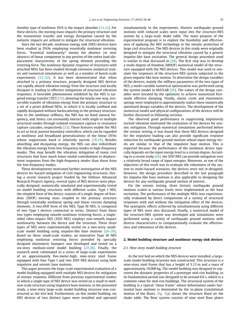
As the test bed on which the NES devices were installed, a large-scale model building structure was constructed. This structure is anine-story steel frame that has a height of 5.12 m and a mass ofapproximately 10,000 kg. The model building was designed to rep-resent the dynamic properties of a prototype mid-rise building, soits fundamental period was designed to be around 0.6 s, which is acommon value for mid-rise buildings. The structural system of thebuilding is a typical ‘‘shear frame’’ whose deformation under hor-izontal base motions is dominated by the in-plane translationalmotion of the floors. Fig. 1(a) shows the structure fixed on theshake table. The floor system consists of nine steel floor plates
36 J. Luo et al. / Engineering Structures 77 (2014) 34–48
supported by eight steel columns. All of the columns have rectan-gular cross-sections that possess a large aspect ratio, and the longsides of the cross-sections are parallel to the long sides of the floorplates. This design feature leads to significantly different lateralstiffnesses in the two orthogonal directions of the building. Inthe experiments, the structure was excited along the ‘‘loadingdirection’’ shown in Fig. 1(a) so that it can vibrate with large ampli-tudes about the weak axis of the building. Due to the substantiallyhigher stiffness in the other direction, the strong-axis and torsionalresponses caused by the minor asymmetries of the structure andthe load can be neglected. Mild structural steel was used to make
(a) Nine-story model building on shake table
(b) SSVI and Type I NES devices
(c) Strain gages attahced to a first-story central column
Fig. 1. Nine-story model building structure with multiple NESs.
the floor plates while the columns were made of A514 high-strength steel so that the structure can vibrate elastically with suf-ficiently large amplitudes. The specific dimensions of the majorstructural components are listed in Table 1.
After construction of the model building, experimental modaltesting was performed using a sine-sweep base excitation to iden-tify its dynamic properties. During the test, all the NES deviceswere locked to prevent their relative motion with respect to thestructure. Hence, they only act as mass fixed to the structure,and the structural response is basically linear. The natural frequen-cies and mode shapes of the nine translational modes about theweak axis of the structure were identified from the transfer func-tions of acceleration measurements. The identified natural fre-quencies are 1.74, 5.34, 9.10, 12.62, 15.81, 18.76, 21.48, 23.71and 25.27 Hz. Classical damping is assumed and the identifiedmodal damping ratios of the nine translational modes are around0.001, 0.001, 0.002, 0.0023, 0.0027, 0.0055, 0.0055, 0.0032 and0.0035, but they are found to vary slightly with different loadinglevels in the experiments. The possible causes may include shaketable-structure interaction and minor nonlinearities of the struc-tural connections.
2.2. The system of nonlinear energy sink devices
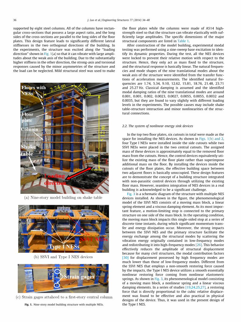
In the top two floor plates, six cutouts in total were made as thespace for installing the NES devices. As shown in Figs. 1(b) and 2,four Type I NESs were installed inside the side cutouts while twoSSVI NESs were placed in the two central cutouts. The assignedmass of these devices is approximately equal to the removed floormass from the cutouts. Hence, the control devices equivalently uti-lize the existing mass of the floor plate rather than superimposeadditional mass on the floor. By installing the devices inside thecutouts of the floor plates, the effective building space betweentwo adjacent floors is basically unoccupied. These design featuresare to demonstrate the concept of a building structure integratedwith non-parasitic control devices through utilizing the existingfloor mass. However, seamless integration of NES devices in a realbuilding is acknowledged to be a significant challenge.
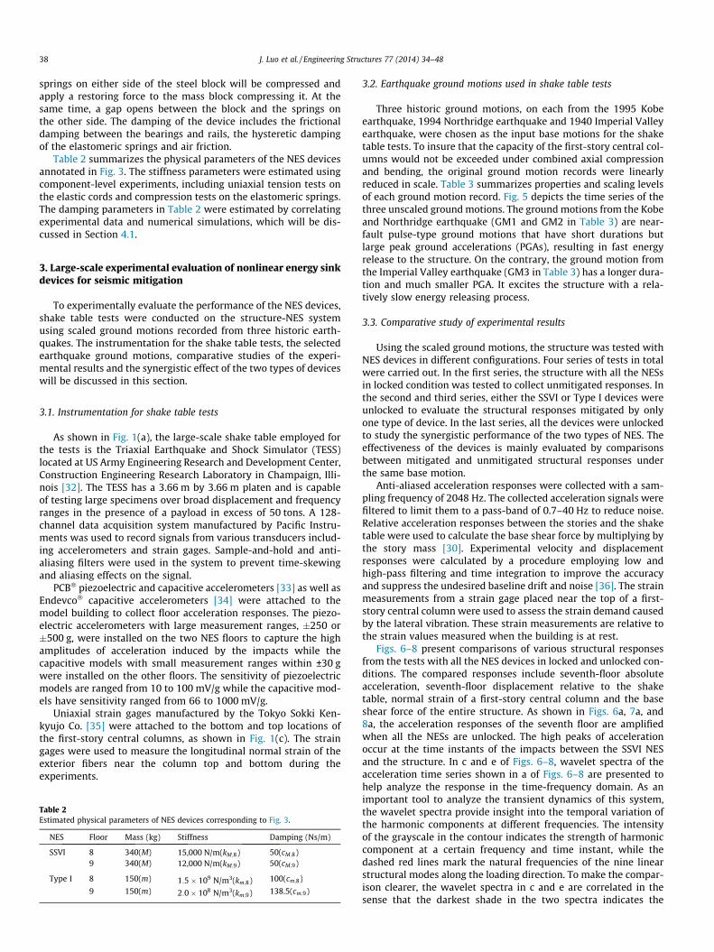
Fig. 3 is a schematic diagram of the structure with multiple NESdevices installed. As shown in the figure, the phenomenologicalmodel of the SSVI NES consists of a moving mass block, a linearspring element and a viscous damping element. As its most impor-tant feature, a motion-limiting stop is connected to the primarystructure on one side of the mass block. In the operating condition,the moving mass block impacts this single-sided stop at a series ofdiscrete time instants, during which significant momentum trans-fer and energy dissipation occur. Moreover, the strong impactsbetween the SSVI NES and the primary structure facilitate theenergy exchange among the structural modes by scattering thevibration energy originally contained in low-frequency modesand redistributing it into high-frequency modes [26]. This behavioreffectively reduces the amplitude of structural displacementbecause for many civil structures, the modal contribution factors[30] for displacement possessed by high frequency modes aremuch lower than those of low-frequency modes. Different fromthe SSVI NES that employs a non-smooth restoring force causedby the impacts, the Type I NES device utilizes a smooth essentiallynonlinear restoring force coming from nonlinear elastomericsprings. As shown in Fig. 3, its phenomenological model consistingof a moving mass block, a nonlinear spring and a linear viscousdamping elements. In a series of studies [19,24,25,27], a restoringforce that is directly proportional to the cubic relative displace-ment was found to be effective and also practical in physicaldesigns of the device. Thus, it was used in the present design ofthe Type I NES.
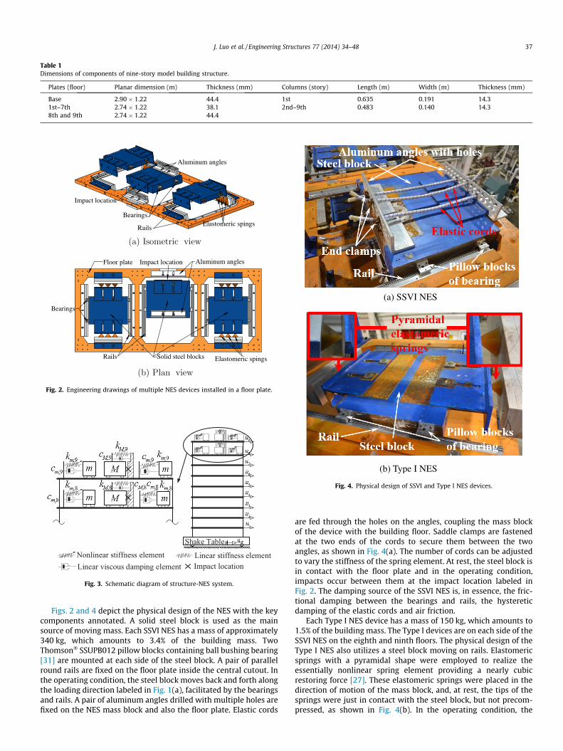
Table 1Dimensions of components of nine-story model building structure.
Plates (floor) Planar dimension (m) Thickness (mm) Columns (story) Length (m) Width (m) Thickness (mm)
Base 2.90 � 1.22 44.4 1st 0.635 0.191 14.31st–7th 2.74 � 1.22 38.1 2nd–9th 0.483 0.140 14.38th and 9th 2.74 � 1.22 44.4
Impact location
Aluminum angles
Rails
Bearings Elastomeric spings
Aluminum angles
Bearings
Rails
Floor plate
Solid steel blocks
Impact location
Elastomeric spings
Fig. 2. Engineering drawings of multiple NES devices installed in a floor plate.
Shake Table
Nonlinear stiffness element Linear stiffness elementLinear viscous damping element Impact location
Fig. 3. Schematic diagram of structure-NES system.
(a) SSVI NES
(b) Type I NES
Fig. 4. Physical design of SSVI and Type I NES devices.
J. Luo et al. / Engineering Structures 77 (2014) 34–48 37
Figs. 2 and 4 depict the physical design of the NES with the keycomponents annotated. A solid steel block is used as the mainsource of moving mass. Each SSVI NES has a mass of approximately340 kg, which amounts to 3.4% of the building mass. TwoThomson� SSUPB012 pillow blocks containing ball bushing bearing[31] are mounted at each side of the steel block. A pair of parallelround rails are fixed on the floor plate inside the central cutout. Inthe operating condition, the steel block moves back and forth alongthe loading direction labeled in Fig. 1(a), facilitated by the bearingsand rails. A pair of aluminum angles drilled with multiple holes arefixed on the NES mass block and also the floor plate. Elastic cords
are fed through the holes on the angles, coupling the mass blockof the device with the building floor. Saddle clamps are fastenedat the two ends of the cords to secure them between the twoangles, as shown in Fig. 4(a). The number of cords can be adjustedto vary the stiffness of the spring element. At rest, the steel block isin contact with the floor plate and in the operating condition,impacts occur between them at the impact location labeled inFig. 2. The damping source of the SSVI NES is, in essence, the fric-tional damping between the bearings and rails, the hystereticdamping of the elastic cords and air friction.
Each Type I NES device has a mass of 150 kg, which amounts to1.5% of the building mass. The Type I devices are on each side of theSSVI NES on the eighth and ninth floors. The physical design of theType I NES also utilizes a steel block moving on rails. Elastomericsprings with a pyramidal shape were employed to realize theessentially nonlinear spring element providing a nearly cubicrestoring force [27]. These elastomeric springs were placed in thedirection of motion of the mass block, and, at rest, the tips of thesprings were just in contact with the steel block, but not precom-pressed, as shown in Fig. 4(b). In the operating condition, the
38 J. Luo et al. / Engineering Structures 77 (2014) 34–48
springs on either side of the steel block will be compressed andapply a restoring force to the mass block compressing it. At thesame time, a gap opens between the block and the springs onthe other side. The damping of the device includes the frictionaldamping between the bearings and rails, the hysteretic dampingof the elastomeric springs and air friction.
Table 2 summarizes the physical parameters of the NES devicesannotated in Fig. 3. The stiffness parameters were estimated usingcomponent-level experiments, including uniaxial tension tests onthe elastic cords and compression tests on the elastomeric springs.The damping parameters in Table 2 were estimated by correlatingexperimental data and numerical simulations, which will be dis-cussed in Section 4.1.
3. Large-scale experimental evaluation of nonlinear energy sinkdevices for seismic mitigation
To experimentally evaluate the performance of the NES devices,shake table tests were conducted on the structure-NES systemusing scaled ground motions recorded from three historic earth-quakes. The instrumentation for the shake table tests, the selectedearthquake ground motions, comparative studies of the experi-mental results and the synergistic effect of the two types of deviceswill be discussed in this section.
3.1. Instrumentation for shake table tests
As shown in Fig. 1(a), the large-scale shake table employed forthe tests is the Triaxial Earthquake and Shock Simulator (TESS)located at US Army Engineering Research and Development Center,Construction Engineering Research Laboratory in Champaign, Illi-nois [32]. The TESS has a 3.66 m by 3.66 m platen and is capableof testing large specimens over broad displacement and frequencyranges in the presence of a payload in excess of 50 tons. A 128-channel data acquisition system manufactured by Pacific Instru-ments was used to record signals from various transducers includ-ing accelerometers and strain gages. Sample-and-hold and anti-aliasing filters were used in the system to prevent time-skewingand aliasing effects on the signal.
PCB� piezoelectric and capacitive accelerometers [33] as well asEndevco� capacitive accelerometers [34] were attached to themodel building to collect floor acceleration responses. The piezo-electric accelerometers with large measurement ranges, �250 or�500 g, were installed on the two NES floors to capture the highamplitudes of acceleration induced by the impacts while thecapacitive models with small measurement ranges within ±30 gwere installed on the other floors. The sensitivity of piezoelectricmodels are ranged from 10 to 100 mV/g while the capacitive mod-els have sensitivity ranged from 66 to 1000 mV/g.
Uniaxial strain gages manufactured by the Tokyo Sokki Ken-kyujo Co. [35] were attached to the bottom and top locations ofthe first-story central columns, as shown in Fig. 1(c). The straingages were used to measure the longitudinal normal strain of theexterior fibers near the column top and bottom during theexperiments.
Table 2Estimated physical parameters of NES devices corresponding to Fig. 3.
NES Floor Mass (kg) Stiffness Damping (Ns/m)
SSVI 8 340(M) 15,000 N/m(kM;8) 50(cM;8)9 340(M) 12,000 N/m(kM;9) 50(cM;9)
Type I 8 150(m) 1:5� 109 N/m3(km;8) 100(cm;8)
9 150(m) 2:0� 108 N/m3(km;9) 138.5(cm;9)
3.2. Earthquake ground motions used in shake table tests
Three historic ground motions, on each from the 1995 Kobeearthquake, 1994 Northridge earthquake and 1940 Imperial Valleyearthquake, were chosen as the input base motions for the shaketable tests. To insure that the capacity of the first-story central col-umns would not be exceeded under combined axial compressionand bending, the original ground motion records were linearlyreduced in scale. Table 3 summarizes properties and scaling levelsof each ground motion record. Fig. 5 depicts the time series of thethree unscaled ground motions. The ground motions from the Kobeand Northridge earthquake (GM1 and GM2 in Table 3) are near-fault pulse-type ground motions that have short durations butlarge peak ground accelerations (PGAs), resulting in fast energyrelease to the structure. On the contrary, the ground motion fromthe Imperial Valley earthquake (GM3 in Table 3) has a longer dura-tion and much smaller PGA. It excites the structure with a rela-tively slow energy releasing process.
3.3. Comparative study of experimental results
Using the scaled ground motions, the structure was tested withNES devices in different configurations. Four series of tests in totalwere carried out. In the first series, the structure with all the NESsin locked condition was tested to collect unmitigated responses. Inthe second and third series, either the SSVI or Type I devices wereunlocked to evaluate the structural responses mitigated by onlyone type of device. In the last series, all the devices were unlockedto study the synergistic performance of the two types of NES. Theeffectiveness of the devices is mainly evaluated by comparisonsbetween mitigated and unmitigated structural responses underthe same base motion.
Anti-aliased acceleration responses were collected with a sam-pling frequency of 2048 Hz. The collected acceleration signals werefiltered to limit them to a pass-band of 0.7–40 Hz to reduce noise.Relative acceleration responses between the stories and the shaketable were used to calculate the base shear force by multiplying bythe story mass [30]. Experimental velocity and displacementresponses were calculated by a procedure employing low andhigh-pass filtering and time integration to improve the accuracyand suppress the undesired baseline drift and noise [36]. The strainmeasurements from a strain gage placed near the top of a first-story central column were used to assess the strain demand causedby the lateral vibration. These strain measurements are relative tothe strain values measured when the building is at rest.
Figs. 6–8 present comparisons of various structural responsesfrom the tests with all the NES devices in locked and unlocked con-ditions. The compared responses include seventh-floor absoluteacceleration, seventh-floor displacement relative to the shaketable, normal strain of a first-story central column and the baseshear force of the entire structure. As shown in Figs. 6a, 7a, and8a, the acceleration responses of the seventh floor are amplifiedwhen all the NESs are unlocked. The high peaks of accelerationoccur at the time instants of the impacts between the SSVI NESand the structure. In c and e of Figs. 6–8, wavelet spectra of theacceleration time series shown in a of Figs. 6–8 are presented tohelp analyze the response in the time-frequency domain. As animportant tool to analyze the transient dynamics of this system,the wavelet spectra provide insight into the temporal variation ofthe harmonic components at different frequencies. The intensityof the grayscale in the contour indicates the strength of harmoniccomponent at a certain frequency and time instant, while thedashed red lines mark the natural frequencies of the nine linearstructural modes along the loading direction. To make the compar-ison clearer, the wavelet spectra in c and e are correlated in thesense that the darkest shade in the two spectra indicates the
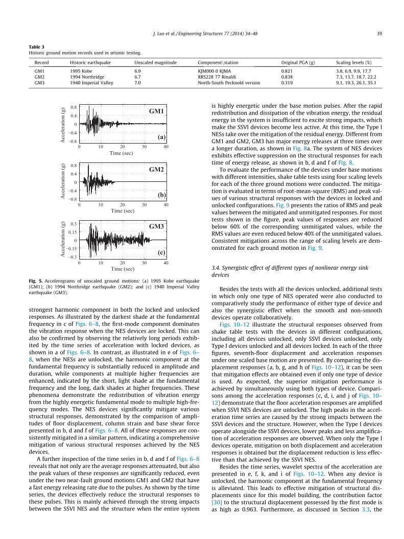
Table 3Historic ground motion records used in seismic testing.
Record Historic earthquake Unscaled magnitude Componentnstation Original PGA (g) Scaling levels (%)
GM1 1995 Kobe 6.9 KJM000 0 KJMA 0.821 3.8, 6.9, 9.9, 17.7GM2 1994 Northridge 6.7 RRS228 77 Rinaldi 0.838 7.3, 13.7, 18.7, 22.2GM3 1940 Imperial Valley 7.0 North-South Pecknold version 0.319 9.1, 19.3, 26.1, 35.1
0 10 20 30 40−0.8
−0.4
0
0.4
0.8
Time (sec)
Acc
eler
atio
n (g
) GM1
(a)
0 10 20 30 40−0.8
−0.4
0
0.4
0.8
Time (sec)
Acc
eler
atio
n (g
)
GM2
(b)
0 10 20 30 40−0.3
−0.15
0
0.15
0.3
Time (sec)
Acc
eler
atio
n (g
)
GM3
(c)
Fig. 5. Accelerograms of unscaled ground motions: (a) 1995 Kobe earthquake(GM1); (b) 1994 Northridge earthquake (GM2); and (c) 1940 Imperial Valleyearthquake (GM3).
J. Luo et al. / Engineering Structures 77 (2014) 34–48 39
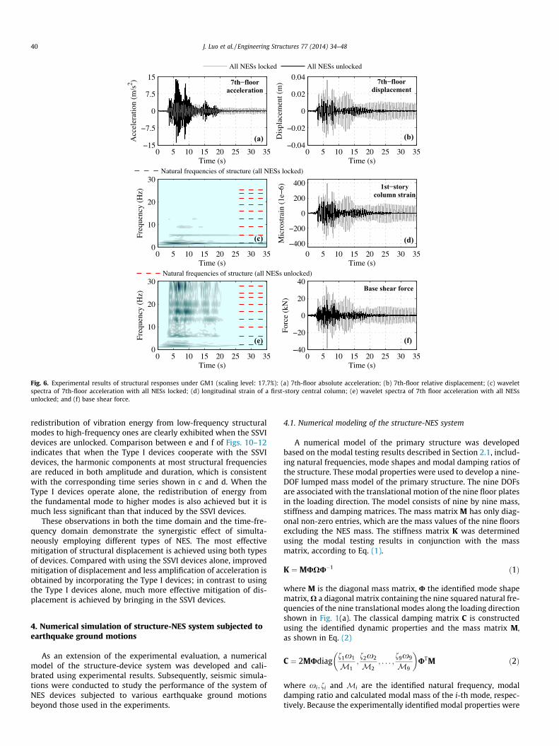
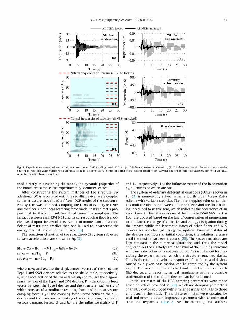
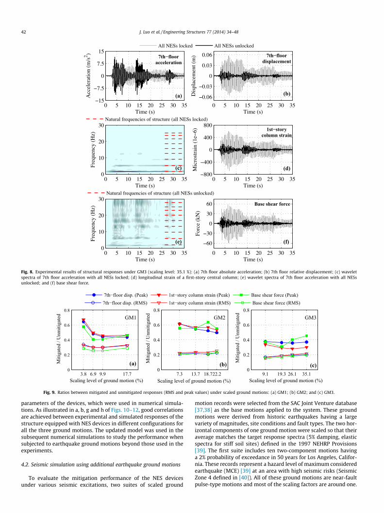
strongest harmonic component in both the locked and unlockedresponses. As illustrated by the darkest shade at the fundamentalfrequency in c of Figs. 6–8, the first-mode component dominatesthe vibration response when the NES devices are locked. This canalso be confirmed by observing the relatively long periods exhib-ited by the time series of acceleration with locked devices, asshown in a of Figs. 6–8. In contrast, as illustrated in e of Figs. 6–8, when the NESs are unlocked, the harmonic component at thefundamental frequency is substantially reduced in amplitude andduration, while components at multiple higher frequencies areenhanced, indicated by the short, light shade at the fundamentalfrequency and the long, dark shades at higher frequencies. Thesephenomena demonstrate the redistribution of vibration energyfrom the highly energetic fundamental mode to multiple high-fre-quency modes. The NES devices significantly mitigate variousstructural responses, demonstrated by the comparison of ampli-tudes of floor displacement, column strain and base shear forcepresented in b, d and f of Figs. 6–8. All of these responses are con-sistently mitigated in a similar pattern, indicating a comprehensivemitigation of various structural responses achieved by the NESdevices.
A further inspection of the time series in b, d and f of Figs. 6–8reveals that not only are the average responses attenuated, but alsothe peak values of these responses are significantly reduced, evenunder the two near-fault ground motions GM1 and GM2 that havea fast energy releasing rate due to the pulses. As shown by the timeseries, the devices effectively reduce the structural responses tothese pulses. This is mainly achieved through the strong impactsbetween the SSVI NES and the structure when the entire system
is highly energetic under the base motion pulses. After the rapidredistribution and dissipation of the vibration energy, the residualenergy in the system is insufficient to excite strong impacts, whichmake the SSVI devices become less active. At this time, the Type INESs take over the mitigation of the residual energy. Different fromGM1 and GM2, GM3 has major energy releases at three times overa longer duration, as shown in Fig. 8a. The system of NES devicesexhibits effective suppression on the structural responses for eachtime of energy release, as shown in b, d and f of Fig. 8.
To evaluate the performance of the devices under base motionswith different intensities, shake table tests using four scaling levelsfor each of the three ground motions were conducted. The mitiga-tion is evaluated in terms of root-mean-square (RMS) and peak val-ues of various structural responses with the devices in locked andunlocked configurations. Fig. 9 presents the ratios of RMS and peakvalues between the mitigated and unmitigated responses. For mosttests shown in the figure, peak values of responses are reducedbelow 60% of the corresponding unmitigated values, while theRMS values are even reduced below 40% of the unmitigated values.Consistent mitigations across the range of scaling levels are dem-onstrated for each ground motion in Fig. 9.
3.4. Synergistic effect of different types of nonlinear energy sinkdevices
Besides the tests with all the devices unlocked, additional testsin which only one type of NES operated were also conducted tocomparatively study the performance of either type of device andalso the synergistic effect when the smooth and non-smoothdevices operate collaboratively.
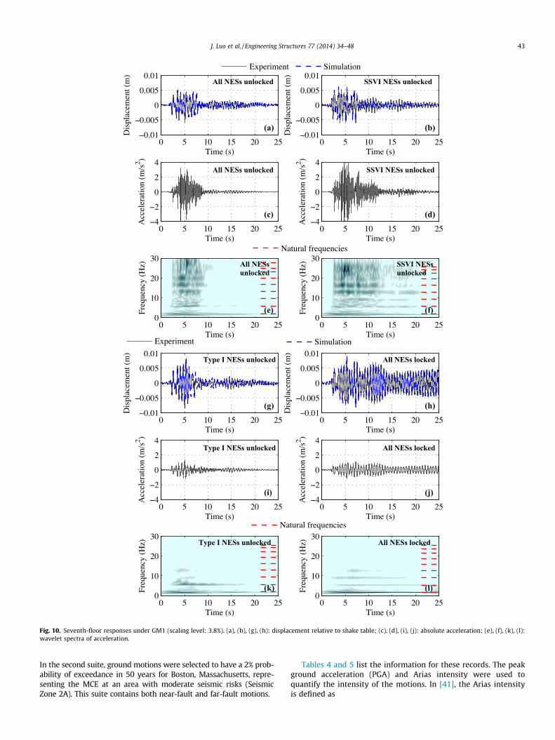
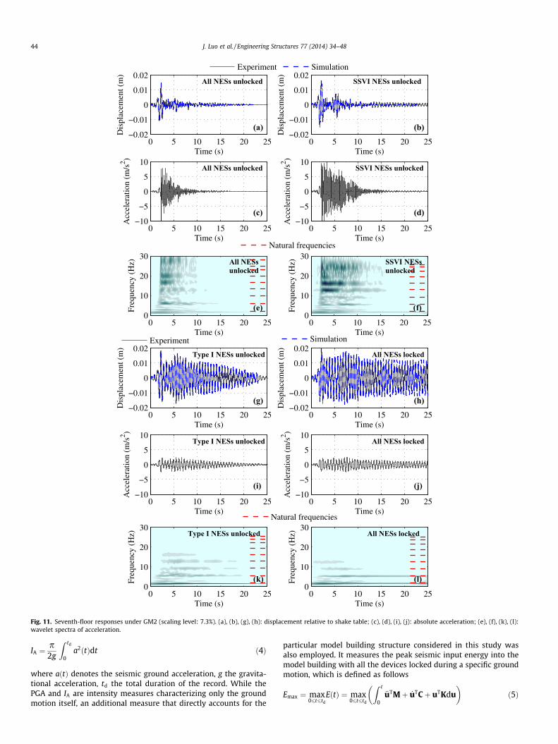
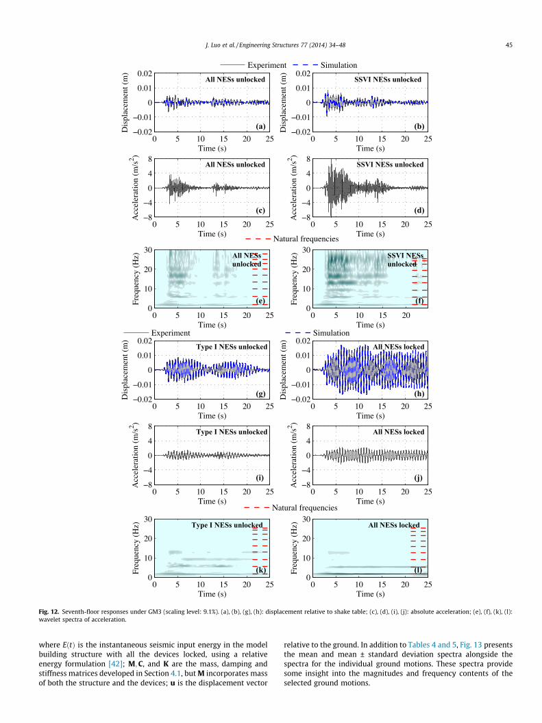
Figs. 10–12 illustrate the structural responses observed fromshake table tests with the devices in different configurations,including all devices unlocked, only SSVI devices unlocked, onlyType I devices unlocked and all devices locked. In each of the threefigures, seventh-floor displacement and acceleration responsesunder one scaled base motion are presented. By comparing the dis-placement responses (a, b, g, and h of Figs. 10–12), it can be seenthat mitigation effects are obtained even if only one type of deviceis used. As expected, the superior mitigation performance isachieved by simultaneously using both types of device. Compari-sons among the acceleration responses (c, d, i, and j of Figs. 10–12) demonstrate that the floor acceleration responses are amplifiedwhen SSVI NES devices are unlocked. The high peaks in the accel-eration time series are caused by the strong impacts between theSSVI devices and the structure. However, when the Type I devicesoperate alongside the SSVI devices, lower peaks and less amplifica-tion of acceleration responses are observed. When only the Type Idevices operate, mitigation on both displacement and accelerationresponses is obtained but the displacement reduction is less effec-tive than that achieved by the SSVI NES.
Besides the time series, wavelet spectra of the acceleration arepresented in e, f, k, and i of Figs. 10–12. When any device isunlocked, the harmonic component at the fundamental frequencyis alleviated. This leads to effective mitigation of structural dis-placements since for this model building, the contribution factor[30] to the structural displacement possessed by the first mode isas high as 0.963. Furthermore, as discussed in Section 3.3, the
0 5 10 15 20 25 30 35−15
−7.5
0
7.5
15
Time (s)
Acc
eler
atio
n (m
/s2 ) 7th−floor
acceleration
(a)
All NESs locked All NESs unlocked
Time (s)
Freq
uenc
y (H
z)
(c)
0 5 10 15 20 25 30 350
10
20
30Natural frequencies of structure (all NESs locked)
Time (s)
Freq
uenc
y (H
z)
(e)
0 5 10 15 20 25 30 350
10
20
30Natural frequencies of structure (all NESs unlocked)
0 5 10 15 20 25 30 35−0.04
−0.02
0
0.02
0.04
Time (s)
Dis
plac
emen
t (m
)
(b)
7th−floordisplacement
0 5 10 15 20 25 30 35−400
−200
0
200
400
Time (s)
Mic
rost
rain
(1e
−6)
(d)
1st−storycolumn strain
0 5 10 15 20 25 30 35−40
−20
0
20
40
Time (s)
Forc
e (k
N)
(f)
Base shear force
Fig. 6. Experimental results of structural responses under GM1 (scaling level: 17.7%): (a) 7th-floor absolute acceleration; (b) 7th-floor relative displacement; (c) waveletspectra of 7th-floor acceleration with all NESs locked; (d) longitudinal strain of a first-story central column; (e) wavelet spectra of 7th floor acceleration with all NESsunlocked; and (f) base shear force.
40 J. Luo et al. / Engineering Structures 77 (2014) 34–48
redistribution of vibration energy from low-frequency structuralmodes to high-frequency ones are clearly exhibited when the SSVIdevices are unlocked. Comparison between e and f of Figs. 10–12indicates that when the Type I devices cooperate with the SSVIdevices, the harmonic components at most structural frequenciesare reduced in both amplitude and duration, which is consistentwith the corresponding time series shown in c and d. When theType I devices operate alone, the redistribution of energy fromthe fundamental mode to higher modes is also achieved but it ismuch less significant than that induced by the SSVI devices.
These observations in both the time domain and the time-fre-quency domain demonstrate the synergistic effect of simulta-neously employing different types of NES. The most effectivemitigation of structural displacement is achieved using both typesof devices. Compared with using the SSVI devices alone, improvedmitigation of displacement and less amplification of acceleration isobtained by incorporating the Type I devices; in contrast to usingthe Type I devices alone, much more effective mitigation of dis-placement is achieved by bringing in the SSVI devices.
4. Numerical simulation of structure-NES system subjected toearthquake ground motions
As an extension of the experimental evaluation, a numericalmodel of the structure-device system was developed and cali-brated using experimental results. Subsequently, seismic simula-tions were conducted to study the performance of the system ofNES devices subjected to various earthquake ground motionsbeyond those used in the experiments.
4.1. Numerical modeling of the structure-NES system
A numerical model of the primary structure was developedbased on the modal testing results described in Section 2.1, includ-ing natural frequencies, mode shapes and modal damping ratios ofthe structure. These modal properties were used to develop a nine-DOF lumped mass model of the primary structure. The nine DOFsare associated with the translational motion of the nine floor platesin the loading direction. The model consists of nine by nine mass,stiffness and damping matrices. The mass matrix M has only diag-onal non-zero entries, which are the mass values of the nine floorsexcluding the NES mass. The stiffness matrix K was determinedusing the modal testing results in conjunction with the massmatrix, according to Eq. (1).
K ¼MUXU�1 ð1Þ
where M is the diagonal mass matrix, U the identified mode shapematrix, X a diagonal matrix containing the nine squared natural fre-quencies of the nine translational modes along the loading directionshown in Fig. 1(a). The classical damping matrix C is constructedusing the identified dynamic properties and the mass matrix M,as shown in Eq. (2)
C ¼ 2MUdiagf1x1
M1;f2x2
M2; . . . ;
f9x9
M9
� �UTM ð2Þ
where xi; fi and Mi are the identified natural frequency, modaldamping ratio and calculated modal mass of the i-th mode, respec-tively. Because the experimentally identified modal properties were
0 5 10 15 20 25 30
−30
−15
0
15
30
Time (s)
Acc
eler
atio
n (m
/s2 ) 7th−floor
acceleration
(a)
All NESs locked All NESs unlocked
Time (s)
Freq
uenc
y (H
z)
(c)
0 5 10 15 20 25 300
10
20
30Natural frequencies of structure (all NESs locked)
Time (s)
Freq
uenc
y (H
z)
(e)
0 5 10 15 20 25 300
10
20
30Natural frequencies of structure (all NESs unlocked)
0 5 10 15 20 25 30−0.08
−0.04
0
0.04
0.08
Time (s)
Dis
plac
emen
t (m
)
(b)
7th−floordisplacement
0 5 10 15 20 25 30−900
−450
0
450
900
Time (s)
Mic
rost
rain
(1e
−6)
(d)
1st−storycolumn strain
0 5 10 15 20 25 30−80
−40
0
40
80
Time (s)
Forc
e (k
N)
Base shear force
(f)
Fig. 7. Experimental results of structural responses under GM2 (scaling level: 22.2 %): (a) 7th floor absolute acceleration; (b) 7th floor relative displacement; (c) waveletspectra of 7th floor acceleration with all NESs locked; (d) longitudinal strain of a first-story central column; (e) wavelet spectra of 7th floor acceleration with all NESsunlocked; and (f) base shear force.
J. Luo et al. / Engineering Structures 77 (2014) 34–48 41
used directly in developing the model, the dynamic properties ofthe model are same as the experimentally identified values.
After constructing the system matrices of the structure, sixadditional DOFs associated with the six NES devices were coupledto the structure model and a fifteen-DOF model of the structure-NES system was obtained. Coupling the DOFs of each Type I NESand the floor, a nonlinear restoring force model that is directly pro-portional to the cubic relative displacement is employed. Theimpact between each SSVI NES and its corresponding floor is mod-eled based upon the law of conservation of momentum and a coef-ficient of restitution smaller than one is used to incorporate theenergy dissipation during the impacts [26].
The equations of motion of the structure-NES system subjectedto base accelerations are shown in Eq. (3).
M€uþ C _uþ Ku ¼ �M1€ug þ GIFI þ GVIFVI ð3aÞmI €wI ¼ �mI1€ug � FI ð3bÞmVI €wVI ¼ �mVI1€ug � FVI ð3cÞ
where u;wI and wVI are the displacement vectors of the structure,Type I and SSVI devices relative to the shake table, respectively;€ug is the acceleration of the shake table; mI and mVI are the diagonalmass matrices of the Type I and SSVI devices; FI is the coupling forcevector between the Type I devices and the structure, each entry ofwhich consists of a nonlinear restoring force and a linear viscousdamping force; FVI is the coupling force vector between the SSVIdevices and the structure, consisting of linear restoring forces andviscous damping forces; GI and GVI are the influence matrix of FI
and FVI, respectively; 1 is the influence vector of the base motion€ug, all entries of which are one.
The system of ordinary differential equations (ODEs) shown inEq. (3) is numerically solved using a fourth-order Runge–Kuttascheme with variable step size. The time-stepping solution contin-ues until the distance between either SSVI NES and the floor hold-ing it reduced to nearly zero, which indicates the occurrence of animpact event. Then, the velocities of the impacted SSVI NES and thefloor are updated based on the law of conservation of momentumto simulate the change of velocities and energy dissipation duringthe impact, while the kinematic states of other floors and NESdevices are not changed. Using the updated kinematic states ofthe devices and floors as initial conditions, the solution resumesuntil the next impact event occurs [26]. The system matrices arekept constant in the numerical simulation and, thus, the modelonly captures the elastodynamic behavior of the building structurewhile inelastic behavior is not considered. This is sufficient for sim-ulating the experiments in which the structure remained elastic.The displacement and velocity responses of the floors and devicescaused by a given base motion can be computed by the systemmodel. The model supports locked and unlocked states of eachNES device, and, hence, numerical simulations with any possibleconfiguration of the multiple devices can be performed.
Initial estimates of the NES damping parameters were madebased on values provided in [28], which are damping parametersof an NES device equipped with similar bearings and rails to thoseemployed in this study. Then, these estimates were updated bytrial and error to obtain improved agreement with experimentalstructural responses. Table 2 lists the damping and stiffness
0 5 10 15 20 25 30 35−15
−7.5
0
7.5
15
Time (s)
Acc
eler
atio
n (m
/s2 ) 7th−floor
acceleration
(a)
All NESs locked All NESs unlocked
Time (s)
Freq
uenc
y (H
z)
(c)
0 5 10 15 20 25 30 350
10
20
30Natural frequencies of structure (all NESs locked)
Time (s)
Freq
uenc
y (H
z)
(e)
0 5 10 15 20 25 30 350
10
20
30Natural frequencies of structure (all NESs unlocked)
0 5 10 15 20 25 30 35
−0.06
−0.03
0
0.03
0.06
Time (s)
Dis
plac
emen
t (m
) 7th−floordisplacement
(b)
0 5 10 15 20 25 30 35−800
−400
0
400
800
Time (s)
Mic
rost
rain
(1e
−6)
(d)
1st−storycolumn strain
0 5 10 15 20 25 30 35
−60
−30
0
30
60
Time (s)
Forc
e (k
N)
(f)
Base shear force
Fig. 8. Experimental results of structural responses under GM3 (scaling level: 35.1 %): (a) 7th floor absolute acceleration; (b) 7th floor relative displacement; (c) waveletspectra of 7th floor acceleration with all NESs locked; (d) longitudinal strain of a first-story central column; (e) wavelet spectra of 7th floor acceleration with all NESsunlocked; and (f) base shear force.
3.8 6.9 9.9 17.70
0.2
0.4
0.6
0.8
Miti
gate
d / U
nmiti
gate
d
Scaling level of ground motion (%)
GM1
(a)
7th−floor disp. (Peak) 1st−story column strain (Peak) Base shear force (Peak)
7.3 13.7 18.722.20
0.2
0.4
0.6
0.8
Miti
gate
d / U
nmiti
gate
d
Scaling level of ground motion (%)
(b)
GM2
7th−floor disp. (RMS) 1st−story column strain (RMS) Base shear force (RMS)
9.1 19.3 26.1 35.10
0.2
0.4
0.6
0.8
Miti
gate
d / U
nmiti
gate
d
Scaling level of ground motion (%)
(c)
GM3
Fig. 9. Ratios between mitigated and unmitigated responses (RMS and peak values) under scaled ground motions: (a) GM1; (b) GM2; and (c) GM3.
42 J. Luo et al. / Engineering Structures 77 (2014) 34–48
parameters of the devices, which were used in numerical simula-tions. As illustrated in a, b, g and h of Figs. 10–12, good correlationsare achieved between experimental and simulated responses of thestructure equipped with NES devices in different configurations forall the three ground motions. The updated model was used in thesubsequent numerical simulations to study the performance whensubjected to earthquake ground motions beyond those used in theexperiments.
4.2. Seismic simulation using additional earthquake ground motions
To evaluate the mitigation performance of the NES devicesunder various seismic excitations, two suites of scaled ground
motion records were selected from the SAC Joint Venture database[37,38] as the base motions applied to the system. These groundmotions were derived from historic earthquakes having a largevariety of magnitudes, site conditions and fault types. The two hor-izontal components of one ground motion were scaled so that theiraverage matches the target response spectra (5% damping, elasticspectra for stiff soil sites) defined in the 1997 NEHRP Provisions[39]. The first suite includes ten two-component motions havinga 2% probability of exceedance in 50 years for Los Angeles, Califor-nia. These records represent a hazard level of maximum consideredearthquake (MCE) [39] at an area with high seismic risks (SeismicZone 4 defined in [40]). All of these ground motions are near-faultpulse-type motions and most of the scaling factors are around one.
0 5 10 15 20 25−4
−2
0
2
4
Time (s)
Acc
eler
atio
n (m
/s2 )
All NESs unlocked
(c)
0 5 10 15 20 25−4
−2
0
2
4
Time (s)
Acc
eler
atio
n (m
/s2 )
SSVI NESs unlocked
(d)
0 5 10 15 20 25−4
−2
0
2
4
Time (s)
Acc
eler
atio
n (m
/s2 )
Type I NESs unlocked
(i)
0 5 10 15 20 25−4
−2
0
2
4
Time (s)
Acc
eler
atio
n (m
/s2 )
All NESs locked
(j)
0 5 10 15 20 25−0.01
−0.005
0
0.005
0.01
Time (s)
Dis
plac
emen
t (m
)(a)
All NESs unlocked
0 5 10 15 20 25−0.01
−0.005
0
0.005
0.01
Time (s)
Dis
plac
emen
t (m
)
(b)
SSVI NESs unlocked
0 5 10 15 20 25−0.01
−0.005
0
0.005
0.01
Time (s)
Dis
plac
emen
t (m
)
Type I NESs unlocked
(g)
0 5 10 15 20 25−0.01
−0.005
0
0.005
0.01
Time (s)
Dis
plac
emen
t (m
)
All NESs locked
(h)
Time (s)
Freq
uenc
y (H
z)
(e)
All NESsunlocked
0 5 10 15 20 250
10
20
30Natural frequencies
Time (s)
Freq
uenc
y (H
z)(f)
SSVI NESsunlocked
0 5 10 15 20 250
10
20
30
Time (s)
Freq
uenc
y (H
z)
(k)
Type I NESs unlocked
0 5 10 15 20 250
10
20
30Natural frequencies
Time (s)
Freq
uenc
y (H
z)
(l)
All NESs locked
0 5 10 15 20 250
10
20
30
SimulationExperiment
Experiment Simulation
Fig. 10. Seventh-floor responses under GM1 (scaling level: 3.8%). (a), (b), (g), (h): displacement relative to shake table; (c), (d), (i), (j): absolute acceleration; (e), (f), (k), (l):wavelet spectra of acceleration.
J. Luo et al. / Engineering Structures 77 (2014) 34–48 43
In the second suite, ground motions were selected to have a 2% prob-ability of exceedance in 50 years for Boston, Massachusetts, repre-senting the MCE at an area with moderate seismic risks (SeismicZone 2A). This suite contains both near-fault and far-fault motions.
Tables 4 and 5 list the information for these records. The peakground acceleration (PGA) and Arias intensity were used toquantify the intensity of the motions. In [41], the Arias intensityis defined as
0 5 10 15 20 25−10
−5
0
5
10
Time (s)
Acc
eler
atio
n (m
/s2 )
All NESs unlocked
(c)
0 5 10 15 20 25−10
−5
0
5
10
Time (s)
Acc
eler
atio
n (m
/s2 )
SSVI NESs unlocked
(d)
0 5 10 15 20 25−10
−5
0
5
10
Time (s)
Acc
eler
atio
n (m
/s2 )
Type I NESs unlocked
(i)
0 5 10 15 20 25−10
−5
0
5
10
Time (s)
Acc
eler
atio
n (m
/s2 )
All NESs locked
(j)
0 5 10 15 20 25−0.02
−0.01
0
0.01
0.02
Time (s)
Dis
plac
emen
t (m
)(a)
All NESs unlocked
0 5 10 15 20 25−0.02
−0.01
0
0.01
0.02
Time (s)
Dis
plac
emen
t (m
)
(b)
SSVI NESs unlocked
0 5 10 15 20 25−0.02
−0.01
0
0.01
0.02
Time (s)
Dis
plac
emen
t (m
)
Type I NESs unlocked
(g)
0 5 10 15 20 25−0.02
−0.01
0
0.01
0.02
Time (s)
Dis
plac
emen
t (m
)
All NESs locked
(h)
Experiment Simulation
Experiment SimulationTime (s)
Freq
uenc
y (H
z)
(e)
All NESsunlocked
0 5 10 15 20 250
10
20
30Natural frequencies
Time (s)
Freq
uenc
y (H
z)
(f)
SSVI NESsunlocked
0 5 10 15 20 250
10
20
30
Time (s)
Freq
uenc
y (H
z)
(k)
Type I NESs unlocked
0 5 10 15 20 250
10
20
30Natural frequencies
Time (s)
Freq
uenc
y (H
z)
(l)
All NESs locked
0 5 10 15 20 250
10
20
30
Fig. 11. Seventh-floor responses under GM2 (scaling level: 7.3%). (a), (b), (g), (h): displacement relative to shake table; (c), (d), (i), (j): absolute acceleration; (e), (f), (k), (l):wavelet spectra of acceleration.
44 J. Luo et al. / Engineering Structures 77 (2014) 34–48
IA ¼p2g
Z td
0a2ðtÞdt ð4Þ
where aðtÞ denotes the seismic ground acceleration, g the gravita-tional acceleration, td the total duration of the record. While thePGA and IA are intensity measures characterizing only the groundmotion itself, an additional measure that directly accounts for the
particular model building structure considered in this study wasalso employed. It measures the peak seismic input energy into themodel building with all the devices locked during a specific groundmotion, which is defined as follows
Emax ¼ max06t6td
EðtÞ ¼ max06t6td
Z t
0
€uTMþ _uTCþ uTKdu� �
ð5Þ
0 5 10 15 20 25−8
−4
0
4
8
Time (s)
Acc
eler
atio
n (m
/s2 )
All NESs unlocked
(c)
0 5 10 15 20 25−8
−4
0
4
8
Time (s)
Acc
eler
atio
n (m
/s2 )
SSVI NESs unlocked
(d)
0 5 10 15 20 25−8
−4
0
4
8
Time (s)
Acc
eler
atio
n (m
/s2 )
Type I NESs unlocked
(i)
0 5 10 15 20 25−8
−4
0
4
8
Time (s)
Acc
eler
atio
n (m
/s2 )
All NESs locked
(j)
0 5 10 15 20 25−0.02
−0.01
0
0.01
0.02
Time (s)
Dis
plac
emen
t (m
)(a)
All NESs unlocked
0 5 10 15 20 25−0.02
−0.01
0
0.01
0.02
Time (s)
Dis
plac
emen
t (m
)
(b)
SSVI NESs unlocked
0 5 10 15 20 25−0.02
−0.01
0
0.01
0.02
Time (s)
Dis
plac
emen
t (m
)
Type I NESs unlocked
(g)0 5 10 15 20 25
−0.02
−0.01
0
0.01
0.02
Time (s)
Dis
plac
emen
t (m
)
All NESs locked
(h)
Experiment Simulation
Experiment SimulationTime (s)
Freq
uenc
y (H
z)
(e)
All NESsunlocked
0 5 10 15 20 250
10
20
30Natural frequencies
Time (s)
Freq
uenc
y (H
z)(f)
SSVI NESsunlocked
0 5 10 15 200
10
20
30
Time (s)
Freq
uenc
y (H
z)
(k)
Type I NESs unlocked
0 5 10 15 20 250
10
20
30Natural frequencies
Time (s)
Freq
uenc
y (H
z)
(l)
All NESs locked
0 5 10 15 20 250
10
20
30
Fig. 12. Seventh-floor responses under GM3 (scaling level: 9.1%). (a), (b), (g), (h): displacement relative to shake table; (c), (d), (i), (j): absolute acceleration; (e), (f), (k), (l):wavelet spectra of acceleration.
J. Luo et al. / Engineering Structures 77 (2014) 34–48 45
where EðtÞ is the instantaneous seismic input energy in the modelbuilding structure with all the devices locked, using a relativeenergy formulation [42]; M;C, and K are the mass, damping andstiffness matrices developed in Section 4.1, but M incorporates massof both the structure and the devices; u is the displacement vector
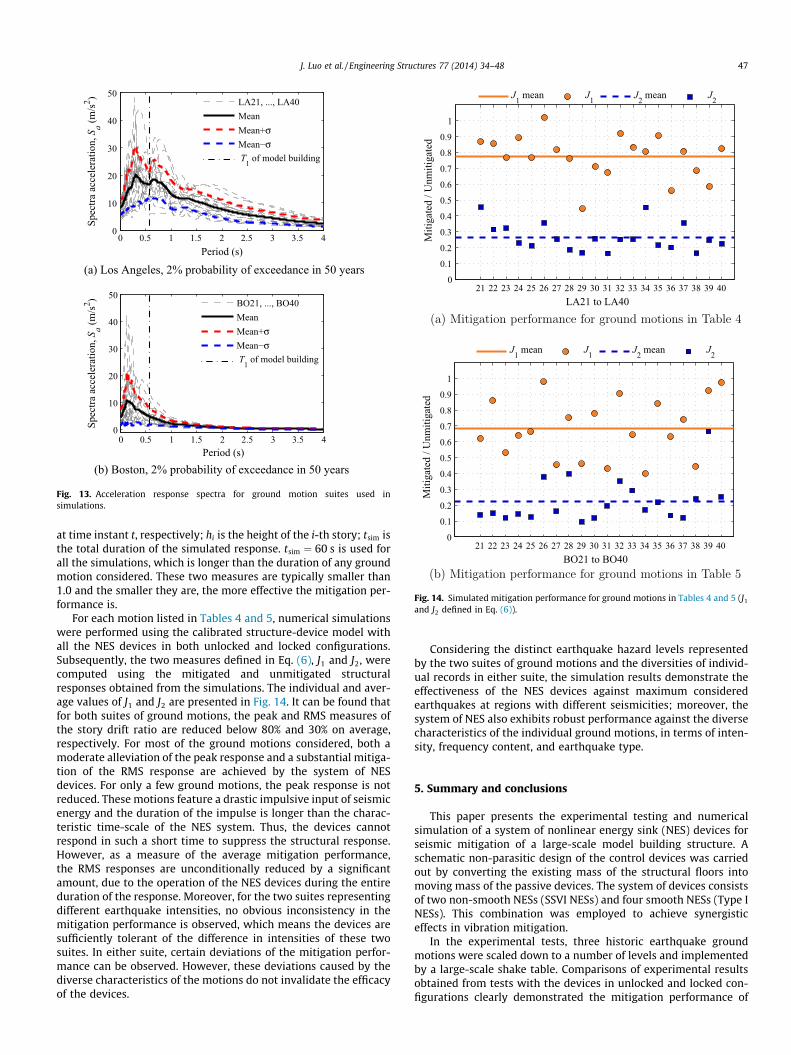
relative to the ground. In addition to Tables 4 and 5, Fig. 13 presentsthe mean and mean ± standard deviation spectra alongside thespectra for the individual ground motions. These spectra providesome insight into the magnitudes and frequency contents of theselected ground motions.
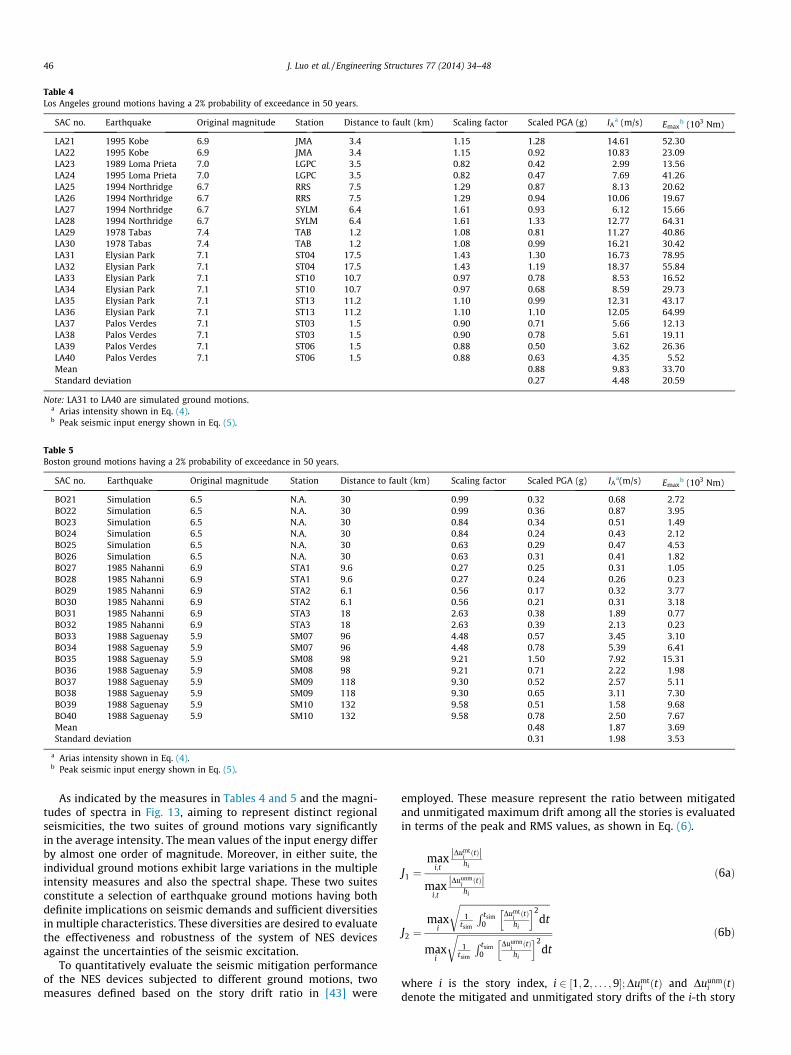
Table 4Los Angeles ground motions having a 2% probability of exceedance in 50 years.
SAC no. Earthquake Original magnitude Station Distance to fault (km) Scaling factor Scaled PGA (g) IAa (m/s) Emax
b (103 Nm)
LA21 1995 Kobe 6.9 JMA 3.4 1.15 1.28 14.61 52.30LA22 1995 Kobe 6.9 JMA 3.4 1.15 0.92 10.83 23.09LA23 1989 Loma Prieta 7.0 LGPC 3.5 0.82 0.42 2.99 13.56LA24 1995 Loma Prieta 7.0 LGPC 3.5 0.82 0.47 7.69 41.26LA25 1994 Northridge 6.7 RRS 7.5 1.29 0.87 8.13 20.62LA26 1994 Northridge 6.7 RRS 7.5 1.29 0.94 10.06 19.67LA27 1994 Northridge 6.7 SYLM 6.4 1.61 0.93 6.12 15.66LA28 1994 Northridge 6.7 SYLM 6.4 1.61 1.33 12.77 64.31LA29 1978 Tabas 7.4 TAB 1.2 1.08 0.81 11.27 40.86LA30 1978 Tabas 7.4 TAB 1.2 1.08 0.99 16.21 30.42LA31 Elysian Park 7.1 ST04 17.5 1.43 1.30 16.73 78.95LA32 Elysian Park 7.1 ST04 17.5 1.43 1.19 18.37 55.84LA33 Elysian Park 7.1 ST10 10.7 0.97 0.78 8.53 16.52LA34 Elysian Park 7.1 ST10 10.7 0.97 0.68 8.59 29.73LA35 Elysian Park 7.1 ST13 11.2 1.10 0.99 12.31 43.17LA36 Elysian Park 7.1 ST13 11.2 1.10 1.10 12.05 64.99LA37 Palos Verdes 7.1 ST03 1.5 0.90 0.71 5.66 12.13LA38 Palos Verdes 7.1 ST03 1.5 0.90 0.78 5.61 19.11LA39 Palos Verdes 7.1 ST06 1.5 0.88 0.50 3.62 26.36LA40 Palos Verdes 7.1 ST06 1.5 0.88 0.63 4.35 5.52Mean 0.88 9.83 33.70Standard deviation 0.27 4.48 20.59
Note: LA31 to LA40 are simulated ground motions.a Arias intensity shown in Eq. (4).b Peak seismic input energy shown in Eq. (5).
Table 5Boston ground motions having a 2% probability of exceedance in 50 years.
SAC no. Earthquake Original magnitude Station Distance to fault (km) Scaling factor Scaled PGA (g) IAa(m/s) Emax
b (103 Nm)
BO21 Simulation 6.5 N.A. 30 0.99 0.32 0.68 2.72BO22 Simulation 6.5 N.A. 30 0.99 0.36 0.87 3.95BO23 Simulation 6.5 N.A. 30 0.84 0.34 0.51 1.49BO24 Simulation 6.5 N.A. 30 0.84 0.24 0.43 2.12BO25 Simulation 6.5 N.A. 30 0.63 0.29 0.47 4.53BO26 Simulation 6.5 N.A. 30 0.63 0.31 0.41 1.82BO27 1985 Nahanni 6.9 STA1 9.6 0.27 0.25 0.31 1.05BO28 1985 Nahanni 6.9 STA1 9.6 0.27 0.24 0.26 0.23BO29 1985 Nahanni 6.9 STA2 6.1 0.56 0.17 0.32 3.77BO30 1985 Nahanni 6.9 STA2 6.1 0.56 0.21 0.31 3.18BO31 1985 Nahanni 6.9 STA3 18 2.63 0.38 1.89 0.77BO32 1985 Nahanni 6.9 STA3 18 2.63 0.39 2.13 0.23BO33 1988 Saguenay 5.9 SM07 96 4.48 0.57 3.45 3.10BO34 1988 Saguenay 5.9 SM07 96 4.48 0.78 5.39 6.41BO35 1988 Saguenay 5.9 SM08 98 9.21 1.50 7.92 15.31BO36 1988 Saguenay 5.9 SM08 98 9.21 0.71 2.22 1.98BO37 1988 Saguenay 5.9 SM09 118 9.30 0.52 2.57 5.11BO38 1988 Saguenay 5.9 SM09 118 9.30 0.65 3.11 7.30BO39 1988 Saguenay 5.9 SM10 132 9.58 0.51 1.58 9.68BO40 1988 Saguenay 5.9 SM10 132 9.58 0.78 2.50 7.67Mean 0.48 1.87 3.69Standard deviation 0.31 1.98 3.53
a Arias intensity shown in Eq. (4).b Peak seismic input energy shown in Eq. (5).
46 J. Luo et al. / Engineering Structures 77 (2014) 34–48
As indicated by the measures in Tables 4 and 5 and the magni-tudes of spectra in Fig. 13, aiming to represent distinct regionalseismicities, the two suites of ground motions vary significantlyin the average intensity. The mean values of the input energy differby almost one order of magnitude. Moreover, in either suite, theindividual ground motions exhibit large variations in the multipleintensity measures and also the spectral shape. These two suitesconstitute a selection of earthquake ground motions having bothdefinite implications on seismic demands and sufficient diversitiesin multiple characteristics. These diversities are desired to evaluatethe effectiveness and robustness of the system of NES devicesagainst the uncertainties of the seismic excitation.
To quantitatively evaluate the seismic mitigation performanceof the NES devices subjected to different ground motions, twomeasures defined based on the story drift ratio in [43] were
employed. These measure represent the ratio between mitigatedand unmitigated maximum drift among all the stories is evaluatedin terms of the peak and RMS values, as shown in Eq. (6).
J1 ¼max
i;t
DumtiðtÞj j
hi
maxi;t
DuunmiðtÞj j
hi
ð6aÞ
J2 ¼max
i
ffiffiffiffiffiffiffiffiffiffiffiffiffiffiffiffiffiffiffiffiffiffiffiffiffiffiffiffiffiffiffiffiffiffiffiffiffiffiffi1
tsim
R tsim0
DumtiðtÞ
hi
h i2dt
r
maxi
ffiffiffiffiffiffiffiffiffiffiffiffiffiffiffiffiffiffiffiffiffiffiffiffiffiffiffiffiffiffiffiffiffiffiffiffiffiffiffiffiffi1
tsim
R tsim0
DuumniðtÞ
hi
h i2dt
r ð6bÞ
where i is the story index, i 2 ½1;2; . . . ;9�; Dumti ðtÞ and Duunm
i ðtÞdenote the mitigated and unmitigated story drifts of the i-th story
0 0.5 1 1.5 2 2.5 3 3.5 40
10
20
30
40
50
Period (s)
(a) Los Angeles, 2% probability of exceedance in 50 years
Spec
tra a
ccel
erat
ion,
Sa
(m/s
2 ) LA21, ..., LA40MeanMean+σMean−σ T1 of model building
0 0.5 1 1.5 2 2.5 3 3.5 40
10
20
30
40
50
Period (s)(b) Boston, 2% probability of exceedance in 50 years
Spec
tra a
ccel
erat
ion,
Sa
(m/s
2 ) BO21, ..., BO40MeanMean+σMean−σ T1 of model building
Fig. 13. Acceleration response spectra for ground motion suites used insimulations.
21 22 23 24 25 26 27 28 29 30 31 32 33 34 35 36 37 38 39 400
0.1
0.2
0.3
0.4
0.5
0.6
0.7
0.8
0.9
1
LA21 to LA40
Miti
gate
d / U
nmiti
gate
d
J1 mean J1 J2 mean J2
(a) Mitigation performance for ground motions in Table 4
21 22 23 24 25 26 27 28 29 30 31 32 33 34 35 36 37 38 39 400
0.1
0.2
0.3
0.4
0.5
0.6
0.7
0.8
0.9
1
BO21 to BO40
Miti
gate
d / U
nmiti
gate
d
J1 mean J1 J2 mean J2
(b) Mitigation performance for ground motions in Table 5
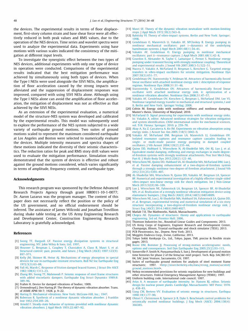
Fig. 14. Simulated mitigation performance for ground motions in Tables 4 and 5 (J1
and J2 defined in Eq. (6)).
J. Luo et al. / Engineering Structures 77 (2014) 34–48 47
at time instant t, respectively; hi is the height of the i-th story; tsim isthe total duration of the simulated response. tsim ¼ 60 s is used forall the simulations, which is longer than the duration of any groundmotion considered. These two measures are typically smaller than1.0 and the smaller they are, the more effective the mitigation per-formance is.
For each motion listed in Tables 4 and 5, numerical simulationswere performed using the calibrated structure-device model withall the NES devices in both unlocked and locked configurations.Subsequently, the two measures defined in Eq. (6), J1 and J2, werecomputed using the mitigated and unmitigated structuralresponses obtained from the simulations. The individual and aver-age values of J1 and J2 are presented in Fig. 14. It can be found thatfor both suites of ground motions, the peak and RMS measures ofthe story drift ratio are reduced below 80% and 30% on average,respectively. For most of the ground motions considered, both amoderate alleviation of the peak response and a substantial mitiga-tion of the RMS response are achieved by the system of NESdevices. For only a few ground motions, the peak response is notreduced. These motions feature a drastic impulsive input of seismicenergy and the duration of the impulse is longer than the charac-teristic time-scale of the NES system. Thus, the devices cannotrespond in such a short time to suppress the structural response.However, as a measure of the average mitigation performance,the RMS responses are unconditionally reduced by a significantamount, due to the operation of the NES devices during the entireduration of the response. Moreover, for the two suites representingdifferent earthquake intensities, no obvious inconsistency in themitigation performance is observed, which means the devices aresufficiently tolerant of the difference in intensities of these twosuites. In either suite, certain deviations of the mitigation perfor-mance can be observed. However, these deviations caused by thediverse characteristics of the motions do not invalidate the efficacyof the devices.
Considering the distinct earthquake hazard levels representedby the two suites of ground motions and the diversities of individ-ual records in either suite, the simulation results demonstrate theeffectiveness of the NES devices against maximum consideredearthquakes at regions with different seismicities; moreover, thesystem of NES also exhibits robust performance against the diversecharacteristics of the individual ground motions, in terms of inten-sity, frequency content, and earthquake type.
5. Summary and conclusions
This paper presents the experimental testing and numericalsimulation of a system of nonlinear energy sink (NES) devices forseismic mitigation of a large-scale model building structure. Aschematic non-parasitic design of the control devices was carriedout by converting the existing mass of the structural floors intomoving mass of the passive devices. The system of devices consistsof two non-smooth NESs (SSVI NESs) and four smooth NESs (Type INESs). This combination was employed to achieve synergisticeffects in vibration mitigation.
In the experimental tests, three historic earthquake groundmotions were scaled down to a number of levels and implementedby a large-scale shake table. Comparisons of experimental resultsobtained from tests with the devices in unlocked and locked con-figurations clearly demonstrated the mitigation performance of
48 J. Luo et al. / Engineering Structures 77 (2014) 34–48
the devices. The experimental results in terms of floor displace-ment, first-story column strain and base shear force were all effec-tively reduced in both peak values and RMS values, due to theoperation of the NES devices. Time series and wavelet spectra wereused to analyze the experimental data. Experiments using basemotions with various scales indicated the consistency of the miti-gation at different input levels.
To investigate the synergistic effect between the two types ofNES devices, additional experiments with only one type of devicein operation were conducted. Comparisons of the experimentalresults indicated that the best mitigation performance wasachieved by simultaneously using both types of devices. Whenthe Type I NESs were used alongside the SSVI NESs, the amplifica-tion of floor acceleration caused by the strong impacts werealleviated and the suppression of displacement responses wasimproved, compared with using SSVI NESs alone. Although usingthe Type I NESs alone can avoid the amplification of floor acceler-ation, the mitigation of displacement was not as effective as thatachieved by the SSVI NESs.
As an extension of the experimental evaluation, a numericalmodel of the structure-NES system was developed and calibratedby the experimental results. This model was subsequently usedto explore the performance of the NES system subjected to a widevariety of earthquake ground motions. Two suites of groundmotions scaled to represent the maximum considered earthquakeat Los Angeles and Boston were selected to numerically evaluatethe devices. Multiple intensity measures and spectra shapes ofthese motions indicated the diversity of their seismic characteris-tics. The reduction ratios for peak and RMS story drift values wereused to evaluate the mitigation performance. Simulation resultsdemonstrated that the system of devices is effective and robustagainst the ground motions considered, which varies significantlyin terms of amplitude, frequency content, and earthquake type.
Acknowledgments
This research program was sponsored by the Defense AdvancedResearch Projects Agency through grant HR0011-10-1-0077;Dr. Aaron Lazarus was the program manager. The content of thispaper does not necessarily reflect the position or the policy ofthe US government, and no official endorsement should beinferred. The assistance of James Wilcoski and Jonathan Trovillionduring shake table testing at the US Army Engineering Researchand Development Center, Construction Engineering ResearchLaboratory is gratefully acknowledged.
References
[1] Soong TT, Dargush GF. Passive energy dissipation systems in structuralengineering. NY: John Wiley & Sons, Ltd; 1997.
[2] Housner G, Bergman L, Caughey T, Chassiakos A, Claus R, Masri S, et al.Structural control: past, present, and future. J Eng Mech (ASCE) 1997;123(9):897–971.
[3] Kelly JM, Skinner RI, Heine AJ. Mechanisms of energy absorption in specialdevices for use in earthquake resistant structures. Bull NZ Soc Earthquake Eng1972;5(3):63–88.
[4] Pall AS, Marsh C. Response of friction damped braced frames. J Struct Div ASCE1982;108(6):1313–23.
[5] Zhang RH, Soong TT, Mahmoodi P. Seismic response of steel frame structureswith added viscoelastic dampers. Earthquake Eng Struct Dynamics 1989;8:389–96.
[6] Frahm H. Device for damped vibrations of bodies; 1909.[7] Ormondroyd J, Den Hartog JP. The theory of dynamic vibration absorber. Trans.
of ASME APM-50-7; 1928. p. 9–22.[8] Hartog D. Mechanical vibrations. New York: McGraw-Hill, Inc.; 1947.[9] Roberson R. Synthesis of a nonlinear dynamic vibration absorber. J Franklin
Inst 1952;254:205–20.[10] Arnold F. Steady-state behavior of systems provided with nonlinear dynamic
vibration absorbers. J Appl Mech 1955;22:487–92.
[11] Masri SF. Theory of the dynamic vibration neutralizer with motion-limitingstops. J Appl Mech 1972;39(2):563–8.
[12] Babitsky VI. Theory of vibro-impact systems. Berlin and New York: Springer;1998.
[13] Gendelman O, Manevitch LI, Vakakis AF, M’Closkey R. Energy pumping innonlinear mechanical oscillators: part i—dynamics of the underlyinghamiltonian systems. J Appl Mech 2001;68(1):34–41.
[14] Vakakis AF, Gendelman O. Energy pumping in nonlinear mechanicaloscillators: part ii—resonance capture. J Appl Mech 2001;68(1):42–8.
[15] Gourdon E, Alexander N, Taylor C, Lamarque C, Pernot S. Nonlinear energypumping under transient forcing with strongly nonlinear coupling: Theoreticaland experimental results. J Sound Vib 2007;300(3-5):522–51.
[16] Nucera F, Vakakis A, McFarland D, Bergman L, Kerschen G. Targeted energytransfers in vibro-impact oscillators for seismic mitigation. Nonlinear Dyn2007;50(3):651–77.
[17] Gendelman OV, Starosvetsky Y, Feldman M. Attractors of harmonically forcedlinear oscillator with attached nonlinear energy sink i: description of responseregimes. Nonlinear Dyn 2008;51:31–46.
[18] Starosvetsky Y, Gendelman OV. Attractors of harmonically forced linearoscillator with attached nonlinear energy sink. ii: optimization of anonlinear vibration absorber. Nonlinear Dyn 2008;51:47–57.
[19] Vakakis AF, Gendelman OV, Kerschen G, Bergman L, McFarland DM, Lee YS.Nonlinear targeted energy transfer in mechanical and structural systems, I andII. Berlin and New York: Springer Verlag; 2008.
[20] Colvin M. Energy sinks with nonlinear stiffness and nonlinear damping,Master’s thesis. University of Maryland; 2010.
[21] McFarland D. Signal processing for experiments with nonlinear energy sinks.In: Vakakis A, editor. Advanced nonlinear strategies for vibration mitigationand system identification. CISM international centre for mechanical sciences,vol. 518. Vienna: Springer; 2010. p. 259–70.
[22] Akay A, Xu Z, Carcaterra A, Ko IM. Experiments on vibration absorption usingenergy sinks. J Acoust Soc Am 2005;118(5):3043–9.
[23] Vakakis AF, McFarland DM, Bergman LA, Manevitch LI, Gendelman OV.Isolated resonance captures and resonance capture cascades leading tosingle- or multi-mode passive energy pumping in damped coupledoscillators. J Vib Acoust 2004;126(2):235–44.
[24] Quinn DD, Hubbard S, Wierschem N, Al-Shudeifat MA, Ott RJ, Luo J, et al.Equivalent modal damping, stiffening and energy exchanges in multi-degree-of-freedom systems with strongly nonlinear attachments. Proc Inst Mech Eng,Part K: J Multi-Body Dyn 2012;226(2):122–46.
[25] Wierschem NE, Quinn DD, Hubbard SA, Al-Shudeifat MA, McFarland DM, Luo J,et al. Passive damping enhancement of a two-degree-of-freedom systemthrough a strongly nonlinear two-degree-of-freedom attachment. J Sound Vib2012;331(25):5393–407.
[26] AL-Shudeifat MA, Wierschem N, Quinn DD, Vakakis AF, Bergman LA, SpencerBF. Numerical and experimental investigation of a highly effective single-sidedvibro-impact non-linear energy sink for shock mitigation. Int J Non-LinearMech 2013;52(0):96–109.
[27] Luo J, Wierschem NE, Fahnestock LA, Bergman LA, Spencer BF, Al-ShudeifatMA, et al. Realization of a strongly nonlinear vibration mitigation device usingelastomeric bumpers. J Eng Mech (ASCE) 2014;140(5):04014009.
[28] Wierschem NE, Luo J, Al-Shudeifat MA, Hubbard SA, Fahnestock LA, Quinn DD,et al. Bergman, experimental testing and numerical simulation of a six-storystructure incorporating a two-degree-of-freedom nonlinear energy sink. JStruct Eng (ASCE) 2014;140(6):04014027.
[29] Matlab 7.0, The Mathworks, Natick, Massachusetts.[30] Chopra AK. Dynamics of structures: theory and applications to earthquake
engineering. 3rd ed. Prentice Hall; 2006.[31] Thomson Industries Inc., Roundrail Linear Guides and Components; 2013.[32] US Army Corps of Engineers, Engineer Research and Development Center,
Champaign, Illinois, Triaxial earthquake and shock simulator (TESS); 2013.[33] PCB Piezotronics, Inc., Depew, New York; 2013.[34] Meggitts Endevco Corp., Irvine, California; 2013.[35] Tokyo Sokki Kenkyujo Co., Ltd., Tokyo, Japan, TML precise & flexible strain
gages; 2013.[36] Boore DM, Bommer JJ. Processing of strong-motion accelerograms: needs,
options and consequences. Soil Dyn Earthquake Eng 2005;25(2):93–115.[37] Somerville P, Smith N, Punyamurthula S, Sun J. Development of ground motion
time histories for phase 2 of the fema/sac steel project. Tech. Rep. SAC/BD-97/04, SAC Joint Venture, Sacramento, CA; 1997.
[38] Suites of earthquake ground motions for analysis of steel moment framestructures; 1997. <http://nisee.berkeley.edu/data/strong_motion/sacsteel/ground_motions.html>.
[39] Nehrp recommended provisions for seismic regulations for new buildings andother structures. Federal Emergency Management Agency (FEMA); 1997.
[40] Uniform building code. International code council; 1997.[41] Arias A. A measure of earthquake intensity. In: Hansen RJ, editor. Seismic
design for nuclear power plants. Cambridge, Massachusetts: MIT Press; 1970.p. 438–83.
[42] Uang CM, Bertero VV. Evaluation of seismic energy in structures. Earthqua1990;19(1):77–90.
[43] Ohtori Y, Christenson R, Spencer Jr B, Dyke S. Benchmark control problems forseismically excited nonlinear buildings. J Eng Mech (ASCE) 2004;130(4):366385.