Flicker Sources and Mitigation
6
M.M. Morcos, J.C. Gomez Flicker Sources and Mitigation Flicker is a power qual- ity problem that affects Voltage fluctuatfi our daily lives. A single in the power si light intensity change can be extremely annoying, de- frequently the, pending on the voltage fluc- tuation amplitude and by the eqi frequency. Flicker was al- ways considered a power ;. quality problem for only in- candescent lamps, but the phenomenon is now becom- ing noticeable in fluorescent lamps due to the increasing system pollution with interharmonics. Voltage fluctuations may originate in the power system, but most frequently they originate in the equipment or load con- nected to it. The primary generators of voltage fluctu- ation are arc furmaces, weld- ers, altemators, and motors. Utilities and potential us- ers of flicker-generating equipment should estimate their effect on other custom- ers beforehand. There are several empirical formulae and graphs that give approx- imate voltage perturbations. Some simple measures are available that can mitigate __ the flicker effect. If no mea- sures are applicable, the solution will demand a large investment on auxiliary equipment or electric system changes, or a large limitation on power availability. Voltage Fluctuation Flicker is defined as the "impression of fluctuating brightness or color, occurring when the frequency of observed variation lies be- tween a few hertz and the fusion frequency of images." When the .1 'Y- ii ns may ori inatvoltage magnitude varies due s y originate to fast load changes, power stem, but most flow to the equipment will normally vary. If the variation are generated is large enough or is within a certain critical frequency pment or range, the equipment perfor- mance can be affected. main problem of voltage fluctuations is usually the ef- fect on lighting loads, mainly when the illumination of the lamp varies with frequencies between and 10 Hz. Addi- tionally, the phenomenon can slightly affect other types of loads, e.g., motors, electronic devices, and process control- lers. Figure 1 shows a bus voltage flicker. Voltage fluctuation is a voltage regulation issue, which is a major problem in the electric power industry. The principal source of volt- age fluctuation leading to flicker is the electric arc fur- nace. Steel companies are r -00 a building more large-capac- ; t _t ity arc furnaces, as the cost S _. z of producing steel with such ' furnaces has become more __ competitive in comparison with the cost of other pro- cesses. Besides, air pollu- tion is more easily controlled with arc furnaces than with other types of furnaces. Electric utilities generally consider arc fur- naces as desirable loads due to the large amount of power re- quired and the high power factor (between 75 and 90%); however, arc furnaces cause numerous problems to the utility. Other loads that can generate voltage fluctuation, such as welders and wind turbines, do not reach the magnitude of the arc furnace perturbations. Sometimes the term voltage fluctuation is erroneously used as voltage sag, due to the old concept that any change in the lamp intensity is a "light flicker." Voltage sag is a reduction in the rms magnitude of the voltage from 10 to 90% with a duration from 0.5 cycle to minute [1]. Noncyclic flicker is defined as IEEE Power Engineering Review, November 2002 M.M. Morcos is with the Department of Electrical and Computer Engineering, Kansas State University, Manhattan, Kansas, USA. J. C. Gomez is with the Elec- tric Power System Protection Institute, Rio Cuarto National University, Rio Cuarto, Cordoba, Argentina. 0272-1 724/02/S1 7.00X)2002 IE 5
Transcript of Flicker Sources and Mitigation

M.M. Morcos, J.C. Gomez
Flicker Sourcesand Mitigation
Flicker is a power qual-ity problem that affects Voltage fluctuatfi
our daily lives. A single in the power silight intensity change can
be extremely annoying, de- frequently the,pending on the voltage fluc-tuation amplitude and by the eqifrequency. Flicker was al-ways considered a power ;.quality problem for only in-candescent lamps, but thephenomenon is now becom-ing noticeable in fluorescentlamps due to the increasingsystem pollution withinterharmonics. Voltagefluctuations may originate inthe power system, but mostfrequently they originate inthe equipment or load con-
nected to it. The primarygenerators of voltage fluctu-ation are arc furmaces, weld-ers, altemators, and motors.
Utilities and potential us-ers of flicker-generatingequipment should estimatetheir effect on other custom-ers beforehand. There areseveral empirical formulaeand graphs that give approx-imate voltage perturbations.Some simple measures are
available that can mitigate __the flicker effect. If no mea-
sures are applicable, the solution will demand a large investmenton auxiliary equipment or electric system changes, or a largelimitation on power availability.
Voltage FluctuationFlicker is defined as the "impression of fluctuating brightness or
color, occurring when the frequency of observed variation lies be-tween a few hertz and the fusion frequency of images." When the
.1
'Y-
ii
nsmay ori inatvoltage magnitude varies dues y originate to fast load changes, power
stem, but most flow to the equipment willnormally vary. If the variationare generated is large enough or is within a
certain critical frequencypment or range, the equipment perfor-
mance can be affected.
main problem of voltagefluctuations is usually the ef-
fect on lighting loads, mainlywhen the illumination of thelamp varies with frequenciesbetween and 10 Hz. Addi-
tionally, the phenomenon can
slightly affect other types ofloads, e.g., motors, electronicdevices, and process control-
lers. Figure 1 shows a busvoltage flicker.
Voltage fluctuation is a
voltage regulation issue,which is a major problem inthe electric power industry.The principal source of volt-age fluctuation leading toflicker is the electric arc fur-nace. Steel companies are
r-00 a building more large-capac-; t _t ity arc furnaces, as the costS _. z of producing steel with such
' furnaces has become more__ competitive in comparison
with the cost of other pro-cesses. Besides, air pollu-
tion is more easily controlled with arc furnaces than with othertypes of furnaces. Electric utilities generally consider arc fur-naces as desirable loads due to the large amount of power re-
quired and the high power factor (between 75 and 90%);however, arc furnaces cause numerous problems to the utility.Other loads that can generate voltage fluctuation, such as
welders and wind turbines, do not reach the magnitude of thearc furnace perturbations.
Sometimes the term voltage fluctuation is erroneously usedas voltage sag, due to the old concept that any change in thelamp intensity is a "light flicker." Voltage sag is a reduction inthe rms magnitude ofthe voltage from 10 to 90% with a durationfrom 0.5 cycle to minute [1]. Noncyclic flicker is defined as
IEEE Power Engineering Review, November 2002
M.M. Morcos is with the Department ofElectrical and Computer Engineering,Kansas State University, Manhattan, Kansas, USA. J. C. Gomez is with the Elec-tric Power System Protection Institute, Rio Cuarto National University, RioCuarto, Cordoba, Argentina.
0272-1 724/02/S1 7.00X)2002 IE 5

a1)0)
0.40.2Time (s)
Figure 1. Bus voltage flicker: supply voltage magnitude, 120 V; supply fre-quency, 60 Hz; voltage variation amplitude, 5.9% ; frequency voltage varia-tion, 10 Hz
that corresponding to occasional voltage fluctuations (less fre-quently than once per hour) such as that caused by the starting ofa motor, a phenomenon considered today as voltage sag [2]. Therepetitive character and voltage change magnitude are the prin-cipal differences between the two phenomena.
The concept of voltage fluctuation involves voltage magni-tude and frequency of occurrence. A utility's main concern isusually the restriction placed upon an individual industry dueto the effect upon other customers. Some utilities are con-
cerned with whether unacceptable voltage fluctuations in a
system will result in complaints from customers actually expe-riencing light flicker.
Human EffectLight flicker perception is a physiological process in which theeye and the brain take part. There are three important mecha-nisms that must be taken into account in order to understand thephenomenon:
. Dynamic characteristic of the lamp
. Nonlinear frequency characteristics of the eye/brain
. Adaptive time of the eye/brain.These mechanisms should be included in any flicker-measur-
ing device in order to reproduce the human effect.
Equipment EffectNo damage to equipment due to the flicker phenomenon has beenreported. Complaints are issued from time to time, but most origi-nate from voltage sags rather than from voltage fluctuations.
Permissible Levels of FlickerAs light flicker is the principal effect of voltage fluctuations, theprocedure to determine the detection and permissible levels willbe considered according to American and European develop-ments. The human factor is of great importance, and the lightingtype and intensity have considerable influence on the phenome-non. Other factors, such as ambient lighting level, room decora-tion, observer interest, and awareness, should be considered.Smaller wattage incandescent lamps change illumination more
quickly upon a change in voltage than lamps with heavier fila-ments due to their smaller thermal-time constant. Cyclic or rap-idly recurring voltage changes are generally more objectionablethan noncyclic; such factors complicate the problem of assign-ing limits to permissible voltage fluctuations.
6
Voltage flicker has generally been described in terms of in-candescent light flickering; however, its effect on fluorescentlighting has recently attracted the attention of both utilities andresearchers [3]. Numerous investigators have studied lightflicker; perhaps the most complete treatment of the subject wascarried out as early as 1937, with one of the results being acurve showing the cyclic pulsation of voltage at which lightflicker of a 115 V tungsten-filament lamp is just perceptible.The investigated frequency range was between 1 and 20 Hz,since, at higher frequencies, the phenomenon known as flickerfusion frequency (FFF) or critical fusion frequency (CFF) be-comes dominant. The FFF is that frequency level (between ap-proximately 40 and 56 Hz) above which the human eye doesnot perceive the flicker. Voltage fluctuations as low as 0.3 Vwere perceptible in 10% of the observations when the rate ofvariation was 8 cycles per second. In order for the variations tobe perceptible in 90% of the observations, for the same fre-quency, the voltage should be over 1 V. The range from 6 to 12Hz was the most critical frequency span.
Results of voltage flicker studies conducted around 1930 byGeneral Electric were directed to the production of the border-lines of both visibility and irritation. The curve included inGeneral Electric's Distribution Data Book has been widelyadopted by electric utilities. Westinghouse (in Electric UtilityEngineering Reference Book, Volume 3) published the resultsof a survey performed in 1959 of the flicker limits (or stan-dards) used by utilities serving more than one million custom-ers. The author's opinion was that most of the utility limits inapplication had been somewhat conservative. It was also hisopinion that reasonable limits should lie somewhere close tothe threshold of objection curve developed by ConsolidatedEdison, which was lately included in an IEEE Standard [4].The curve shown in Figure 2 is very similar to that previouslypresented by General Electric.
Another interesting study on single-frequency light flickerperception was done in England [5]. Results showed a consis-tently lower sensitivity (minimum perceptibility of 0.37% in-stead of 0.25%) than the GE curve, although the general shapeof both curves is in reasonable agreement. In this work, the man-ner in which the human eye perceives light flicker caused bymultiple sine-wave voltage disturbances was investigated. Re-sults show that the eye perceives light flicker in terms ofweighted root of the sum of the squares of the individual fre-quency components. If the two frequencies were in close prox-imity, then the sum of the components would be moreappropriate. This is one of the first references in which flicker isconsidered as a combined effect of several frequency compo-nents acting together, a concept that, after a long development,lead to the European flicker meter [5]. On the other hand, Amer-ican electric utilities have done very little research in on the sub-ject of flicker in recent years.
The International Electrotechnical Commission (IEC) hasstandardized a flicker meter that incorporates weighting curvesthat represent the response of the human eye to light variationsproduced in a 60 W, 230 V (also adapted to 120 V) double-coiled filament incandescent lamp. The meter output is given asper-unit flicker voltage, where one per unit is the level thatshould cause noticeable and annoying light flicker, consideredas the perception threshold for 50% of the human population.Flicker is defined in terms of incandescent lamps for its com-mon usage and sensitivity to voltage changes. Flicker is also ob-served with fluorescent lamps.
The European flicker measurement standards are IEC 868(initially presented in 1986), IEC 868 Amendment 1 (1990), and
IEEE Power Engineering Review, November 2002

IEC 61000-4-15 (1997), which give the specifics of a measure-
ment approach for flicker that can be adapted to a wide varietyof situations. The instrument is a specialized amplitude-modula-tion (AM) analyzer in which the carrier frequency is the mainfrequency, plus post-detection band-pass filtering to mimic theresponse characteristic of the lamp-eye-brain system [6].
Arc FurnacesElectric arc furnace loads often represent the single largestcustomer of an electric power utility system. Today, it is notunusual to provide power to arc furnace plants with supplytransformer ratings in excess of 100 MVA. Installations with200 MVA rating have also been reported. A typical arc furnacewill produce about 1 ton of steel per hour perMW of power in-put. About 450 to 600 kWh of heat energy are required to pro-cess a ton of cold scrap into usable molten steel. The arc issustained by an alternating current, and direct current furnacesare beginning to be popular. In the event that the arc lengthwould not change with time, the arc voltage/current character-istic would be time-invariant. The furnace would not give rise
to voltage fluctuations at the point ofcommon coupling (PCC),but only to voltage and current harmonics due to the intrinsicnonlinearity of the arc characteristic.
Voltage Variation StudiesExtensive studies on arc furnace loads have shown that voltagevariations, which it generates, with multiple frequencies, can
produce objectionable light flicker. Currently the main cause ofcustomer complaints due to light flicker is the voltage fluctua-tion generated by arc furnaces.
An arc furnace can operate without causing interference ifthe short circuit power at the supply terminal, when at its lowestlevel, is at least 80 to 100 times higher than the furnace power, a
figure that should be halved when applied to dc furnaces. Thisapproximation is extensively used as a rule-of-thumb for initialassessments [7]. However, the two parameters that mainly deter-mine voltage fluctuations produced by the furnace are the sys-tem impedance up to PCC and the impedance of the transformerplus the furnace. In 1966, a new constant was defined, the shortcircuit voltage depression (SCVD), which relates the arc fur-nace size to the system strength, that is, the change in voltage atthe PCC occurring when the furnace electrodes are taken fromopen to short circuit by dipping them in the molten charge.
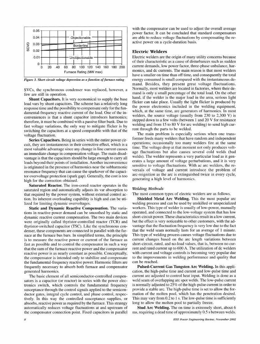
As the SCVD value changes with the arc furnace size, a sur-
vey was carried out in the U.K. in order to find the relationshipbetween this value and the number of customer complaints. Thesurvey results, together with the data compiled by the Interna-tional Union for Electroheat (UIE) and the International Unionof Producers and Distributors of Electric Energy (UNIPEDE),allow the construction of the graph shown in Figure 3, which hasbeen divided into three sections that correspond to objection-able, borderline, and unobjectionable SCVD values [7]. One ofthe actual trends is to use the SCVD value as a rough guide, inorder to determine if the present situation is acceptable or fur-ther study is necessary. Furthermore, it can be decided at the de-sign stage whether a planned installation of a new furnace willcause objectionable flicker.
The rapid improvements of power electronics technologieshave enabled ac competitive applications requiring high powerrectification, one of which is the dc arc furnace. The number of
dc arc furnace installations has increased rapidly in recent years(the first one was started in Germany in 1982), with the size of a
single unit reaching over 200 MW. The dc furnace typically has
IEEE Power Engineering Review, November 2002
5-004D. 3 \ K A/ Borderline of Irritation
a)3cm Borderline of Visibility of FlickerCZ
0I1 10 100 1000 10000 100000
Frequency of dips (1/Hour)
Figure 2. IEEE Standard 141-1993 curve ofborderlines ofvisibility and ir-ritation
less than one-third to one-half of the voltage fluctuations of anac arc furnace of similar size [7]. The main disadvantage of thedc furnace is the cost of high power semiconductors and ac linefilters. Also, dc arc furnaces generate much more harmonicsthan expected and cause flicker problems at remote locations(this time in fluorescent light), apparently due to improperly de-signed arc furnace filters. In this case, a near third harmonic(187 Hz) was presented with a magnitude of about 0.7% of thefundamental, causing a beating phenomenon. The same prob-lem can exist when ac arc furnaces and static var compensators(SVC) are installed together [3].A prediction of flicker levels associated with specific fur-
naces requires an accurate representation of the arc furnaceloads. One of the most important parts of the furnace load is theac electric arc. Calculation of the electrical properties of ac arc isdifficult because the dynamic behavior of the arc depends onseveral variables which are not fully understood. The arc varia-tion depends on the materials being melted and on the arc lengthand is highly random in nature. It has been found that arc varia-tions do not obey any uniform distribution.
Numerous attempts have been made to study the manner inwhich installed furnace load, system short circuit levels, and ob-served flicker levels are interrelated; no satisfactory predictivetechnique seems to have been developed. Such a model, to-gether with the flicker meter model, could be then used in simu-lation studies to assess voltage fluctuations and to study themerits of different compensation schemes.
Mitigation of Voltage FluctuationsWhen compared with other power quality troublesome emis-sions, flicker emission lends itself to being quite expensive tosolve. Repercussions on main supplies can be moderated by al-tering conditions in the supply, for example, increasing the fur-nace reactance by installing a choke. However, this leads toundesirable power reduction. Reducing the system reactance byreinforcing the main supply, or by moving the PCC upstream,both are quite expensive measures.
Light flicker caused by arc furnaces is mainly due to the reac-tive power flow from the system; therefore, any measure takentowards its control will partially reduce voltage fluctuations. Amajor advantage is that the reactive power supplied for the VARcompensator increases the steel production considerably. Themain mitigation methodologies are as follows.
Synchronous Condenser. The first solution was imple-mented by the installation of synchronous condensers in paral-lel with the system as a means of reducing system reactance.With the development of high-power semiconductors and
0.05
0.04 -Objectionablo 0.03 Borderline(D 0.02 _
0.01 Unobjectionable -
0 20 40 60 80 100 120 140 160 180 260Furnace Rating (MW max)
Figure 3. Short circuit voltage depression as a function offurnace rating
SVCs, the synchronous condenser was replaced, however, a
few are still in operation.Shunt Capacitors. It is very economical to supply the base
load vars by shunt capacitors. The scheme has a relatively longresponse time and the possibility to compensate only for the fun-damental-frequency reactive current of the load. One of the in-conveniences is that a shunt capacitor introduces harmonics;therefore, it must be combined with a passive filter bank. Due tofast voltage variations, the only way to mitigate flicker is byswitching the capacitors at a speed comparable with that of thevoltage fluctuation.
Series Capacitors. Being in series with the entire power cir-cuit, they are instantaneous in their corrective effect, which is a
most valuable advantage since any change in line current causes
an immediate change in compensation voltage. The main disad-vantage is that the capacitors should be large enough to carry allloads beyond their points of installation. Another inconvenienceis originated in the presence of harmonics near the subharmonicresonance frequency that can cause the sparkover of the capaci-tor overvoltage protection (spark gap). Generally, the cost is toohigh for the correction obtained.
Saturated Reactor. The iron-cored reactor operates in thesaturated region and automatically adjusts its var absorption tothat required by the power system, without external control ac-
tion. Its inherent overloading capability is high and can be uti-lized for limiting dynamic overvoltages.
Static and Dynamic Reactive Compensation. The varia-tions in reactive power demand can be smoothed by static anddynamic reactive current compensation. The two main deviceswere originally called thyristor-controlled reactor (TCR) andthyristor-switched capacitor (TSC). Like the synchronous con-
denser, these components are connected in parallel with the fur-nace at the furnace bus bars. In simplified terms, the principleis to measure the reactive power or current of the furnace as
fast as possible and to control the compensator in such a way
that the sum of the furnace reactive power and the compensatorreactive power is as nearly constant as possible. Conceptually,the compensator is intended only to stabilize and compensatethe fundamental-frequency reactive power. Harmonic filters are
frequently necessary to absorb both furnace and compensatorgenerated harmonics.
The basic element of all semiconductor-controlled compen-sators is a capacitor (or reactor) in series with the power elec-tronics switch, which controls the fundamental frequencysusceptance through the control signals applied to the semicon-ductor gates, integral cycle control, and phase control, respec-tively. In this way the controlled susceptance supplies, or
absorbs, reactive power as required by the furnace. This strategyautomatically reduces voltage fluctuations at and upstream ofthe compensator connection point. Fixed capacitors in parallel
8
with the compensator can be used to adjust the overall averagepower factor. It can be concluded that standard compensatorsare able to reduce voltage fluctuations by compensating the re-active power on a cycle-duration basis.
Electric WeldersElectric welders are the origin of many utility concerns becauseof their characteristic as a cause of disturbances such as suddencurrent demands, low power factor, three-phase unbalance, har-monics, and dc currents. The main reason is that most weldershave a smaller on time than off time, and consequently the totalenergy consumed is small compared with the instantaneous de-mand. Besides, they present great voltage fluctuations.Normally, most welders are located in factories, where their de-mand is only a small percentage of the total load. On the otherhand, if the welder is the major load in the area, serious lightflicker can take place. Usually the light flicker is produced bythe power electronics included in the welding equipment,which, at the same time, are generators of harmonics. In mostwelders, the source voltage (usually from 230 to 2,300 V) isstepped down to a few volts (between 1 and 20 V for resistancewelding and from 15 to 80 V for arc welding) to send high cur-rent through the parts to be welded.
The main problem is especially serious when one trans-former feeds many welders that have random and independentoperations; occasionally too many welders fire at the sametime. The voltage drop at that moment not only produces volt-age fluctuations but also causes several cold welds (badwelds). The welder represents a very particular load as it gen-erates a large amount of voltage perturbations, and it is verysensitive to voltage fluctuations. With ac arc welders, the re-versals of voltage and current introduce the problem ofarc-reignition as the arc is extinguished twice in every cycle,generating a high level of harmonics.
Welding MethodsThe most common types of electric welders are as follows.
Shielded Metal Arc Welding. This the most popular arcwelding process and can be used by unskilled or unspecializedworkers. This type of welder is usually of low-power, manuallyoperated, and connected to the low-voltage system that has lowshort-circuit power. These characteristics result in a low current,but the effect is very noticeable to other customers, with the ad-vantage that the fluctuation frequency is very low due to the factthat the weld seam normally lasts for an average of 1 minute.This type of welding process causes voltage fluctuations due tocurrent changes based on the arc length variations betweenshort-circuit, rated, and no-load values, that is, between no cur-rent and rated current up to 600 A. The utilization of dc welderswith current and voltage controls is becoming very popular dueto the improvements in welding performance and quality thatcan be reached.
Pulsed-Current Gas Tungsten Arc Welding. In this appli-cation, the high-pulse time and current and low-pulse time andcurrent are adjusted to control heat input. Welding is done as aweld seam of overlapping arc spot welds. The low-pulse currentis normally adjusted to 25% of the high-pulse current in order toprovide a stable arc. The high-pulse time is set to allow the for-mation of the molten pool, which has the penetration desired.This may vary from 0.2 to 1 s. The low-pulse time is sufficientlylong to allow the molten pool to partially freeze.
Stud Arc Welding. The on time is extremely short, about 6ms, requiring a dead time of approximately 0.5 s between welds.
IEEE Power Engineering Review, November 2002

The energy for making the weld is stored at a low voltage in
high-capacity capacitors, with a small load fluctuation trans-ferred to the supply. It can be characterized as arc welding andalso as resistance welding, being a hybrid between the two.
Resistance Welding. In this type, the current is appliedthrough electrodes to the parts to be welded, usually sheets ofsteel, iron, copper, etc. Resistance welders are characterized bylarge short-time currents from 1,000 A to as much as 50,000 A(applied only for a few cycles) followed by idle time from sev-
eral cycles up to a few seconds. As the key to a good spot andseam welding is the accurate heat control, the precise magnitudeand duration of the current are maintained by application of con-trolled semiconductors. The succession of individual voltagedips occurs at objectionable frequent intervals, leading to lightflicker. There are several resistance-welding processes, among
which resistance spot welding is the most popular. The weldingcurrent is timed precisely to bring the metal to the welding tem-perature and the melted pieces together in a small spot. If neces-sary, several of these spots are used in order to joint the metalpieces. The controller can be very simple, from merely an on/offtimer to an extremely complex controller having several me-
chanical and electrical steps of operation. From a voltage-fluc-tuation point of view, the whole welding process involvesseveral steps: preheat time, up-slope time, heat time, cool time,down-slope time, quench time, and temper time. Some control-lers use the stored-energy concept, and others use three-phasepower. New controllers include computers and adaptive control,which vary the welding schedule.
Mitigation TechniquesThe usual mitigation techniques are simply based on the com-
pensation of the reactive load using capacitors, which should bedone as soon as the reactive load appears since the main diffi-culty is fast detection and quick compensator connection. Onemethodology is based on the compensation of the reactive de-mand during the welding event using an adaptive var compensa-tor (AVC), which consists of thyristor-switched shuntcapacitors. Over-compensation can even boost the system volt-age and, therefore, may be used as a means of compensating thevoltage drop due to active load current.
When flicker is caused by a welding machine of large size(compared with the system short-circuit power), the solutioncan be reached by direct reactive compensation, using thewelder control circuit for the capacitor switch trigger withoutany delay. This methodology has been successfully applied to a
1.2 MVA welder connected to a low-voltage supply using a
compensator of four stages. A new technique has been recentlypresented, called current-pulse compensation, which is based ongenerating a transient pulse of current that resembles a mirrorimage of the welder current pulse. This transient pulse of currentis injected into the supply to significantly reduce the fundamen-tal and harmonic components of the welder current.
Generators
Prime Movers
Engine-driven generators are probably responsible for most ofthe rare cases of flicker originated out of the load. The origin ofthe fluctuations of generated voltage roots in the change of tan-gential forces and angular velocity. The total voltage variation isthe same as the speed variation, provided that the excitation isconstant, since the field time-constant of a typical engine-driven
IEEE Power Engineering Review, November 2002
generator is about 0.5 to 2 s, which is very large in comparisonwith the range of objectionable flicker.
Recently, this problem is confined to very small power sys-tems or where backup engine-driven generators are used. For in-stance, a 0.7% speed variation in two-stroke, 300 rpm primemovers would generate voltage fluctuation of same percentageand a frequency of 10 Hz. There is a reported case of light flicker(having a magnitude of nearly 3% and a frequency of 7.5 Hz)that has occurred due to misfiring of a four-cycle, 900 rpm,four-cylinder, methane fuel engine. The flicker frequency isvery near the maximum sensitivity of the human eye, and themagnitude is so large that it can annoy 90% of observers. In thiscase, many possible solutions were analyzed, such as adding aflywheel or a very fast excitation system, improving the re-sponse of the speed governor, or adding a static var system [8].
AlternatorsA symmetrical generator with constant load, excitation, and an-gular velocity produces a constant terminal voltage. If any ofthese conditions change, the terminal voltage also varies. It is pos-sible to have a sufficient degree of nonuniformity in the generatorair gap (eccentric rotor and/or stator) to cause pulsating terminalvoltage. However, today's commercial manufacturing tolerancesare so sufficiently close that no case of voltage fluctuation due tothis cause has occurred on power plants. It should be pointed outthat it is always possible to find the problem in alternators incor-rectly designed as well as built, but it is more the exception thanthe general rule. The only advisable action is the correction of thegenerator and prime mover design and/or construction.
Excitation systems are rarely the cause of voltage flicker dueto the high value of the field time-constant, usually more than 3 sfor power plant generators. Therefore, no matter how fast the ex-citation may change, the variation in the armature voltage willbe gradual.
Wind TurbinesThe use of wind turbines in isolated form or in a wind farm is be-coming widespread. At present, the quality of generated voltageand its impact on the power grid, especially high-power fluctua-tions resulting in flicker, are of concern to utilities and custom-ers. The main cause of flicker is due to the frequent switching onand off when the wind drives the generator to a speed around thecut-in speed. The utility to which generators are connected usu-ally limits the number of switching operations to no more thanthree to four times per hour. One possible solution is to keep therotor in standstill until the wind reaches a stable speed beyondthe cut-in value. In this way, a certain hysteresis in the switchingprocess is introduced, which reduces the flicker issue. Thisproblem is very noticeable when many individual generatorsform the wind farm, where the wind energy is not uniformly dis-tributed among them. Another utility compulsory limit is relatedto the network minimum short-circuit level, which should be atleast 20 times the wind generator rating. This limit cannot befulfilled easily due to the fact that strong winds are available inthe non-highly urbanized areas, where the supply systems areusually very weak.
The wind-turbine generator is also characterized by alow-frequency mode of oscillation. Random wind fluctuations,wind shear, and tower shadow effects may excite this mode, pro-ducing large ripple in the driving torque as well as in the gener-ated electric power, which can be noticed as a voltage flicker ofapproximately 0.5% at a frequency between 2 and 4 Hz. A popu-lar wind energy conversion system uses slip power recovery; it
9

employs a double-output induction generator, where the stator isdirectly connected to the grid and the rotor is connected to astatic converter. The existence of ripple in the generated torquemay damage the driven components. Besides, fluctuations of thegenerated electric power may cause a considerable flicker inweak grids. Several control strategies of static converters havebeen designed in order to provide damping to the oscillationmode. One of the proposed control systems follows the windspeed variations resulting in a large reduction of torque rippleand consequently controls the voltage fluctuations.
MotorsIn many cases, the voltage dip created during motor starting, ir-respective of the type of mechanical load, is erroneously consid-ered as voltage fluctuation, because, if it occurs too frequently, itwill cause light flicker. In the current treatment, this voltagedrop should be studied as voltage sag, since the starting fre-quency would not lie in the perception zone (6 to 10 Hz).
Heat PumpsA special situation is presented by heat pumps and air-condi-tioning equipment, which can be called to start as many as eighttimes per hour. Furthermore, the same secondary circuit or do-mestic network can supply more equipment whose additioncauses an important flicker issue. Mitigation can be done inthree ways: reduction of starting frequency, reduction of thestarting current magnitude, or simultaneous reduction of fre-quency and current magnitude. By providing sufficient storageof the generated heat, it is possible to reduce the starts to an ad-visable number of three to four starts per hour.
Reduction of the start current magnitude can be accom-plished by the addition of starters based on metallic resistances,electrolytic resistances, inductances, auto-transformers, elec-tronics (soft starters), etc. In all cases, the solution can be im-proved by the utilization of an off-load valve that equalizes thepressure on both sides of the compressor during starting. An-other possible solution is the use of electronic speed control,which, besides its higher cost, could create another problem dueto harmonic contamination.
Motor-Driven Pulsating (Reciprocating) LoadsThere are types equipment, such as air compressors, pumps,walking-beam oil pumps, etc., for which the motor load variescyclically with each power stroke, thus producing a correspond-ing variation in the line current and subsequent voltage fluctua-tion. Domestic refrigerators have caused this type ofperturbation in the past, but this problem now seldom occurs dueto design improvements that take the fluctuation frequency ofthe load into account. An air compressor driven by a 100 Hpwound-rotor induction motor presents current fluctuations witha maximum of 2.5 times its minimum value, in spite of the motorslip change. Comparatively small variations of voltage may beobjectionable if pulsation occurs 6 to 12 times per second,which is not unusual. For instance, a four-pole induction motordriving a refrigerator compressor has a speed of approximately1,800 rpm, which, when reduced by the normal 3.5 belt/wheelrelation to 514 rpm or 8.6 Hz, would cause a load change in thelowest part of the sensitivity curve. The main solution in thesecases roots in the equipment having enough inertia in order tolimit the variations in the motor armature current to a value notexceeding 66% of the full load current. If this is not the case, aflywheel can be added or a change in the belt/wheel relation canbe made.
The same reciprocating load may be objectionable in oneplace and not noted in another due to the effect of system imped-ance. That means that in a weak circuit the load pulsation willmagnify the voltage fluctuation leading to detectable lightflicker. There are cases of complaints of light flicker caused byrefrigerators' compressors (industrial or commercial), whichcan originate only in extremely weak residential distributionsystems. An analytical treatment of the dynamic behavior of in-duction motor (including the motor and machinery inertia) forconstant plus sinusoidal changing load has been reported, whichis especially applicable to alternative compressors [9].
Motor-Driven Intermittent and Irregular LoadsThe application of motor drives for which the nature of the workcalls for heavy overloads and for cyclic loads of long and irregu-lar periods can lead to light flicker. Motor currents in such in-stallations vary rapidly from light load through pullout at heavycurrent and high power factor to the high locked-rotor current atlow power factor. Saw mills, wood chippers, mixers, punchpresses, and shears are examples of applications where the loadgoes through large variations, but where flywheels and other de-sign features can limit both the rate of application and magni-tude of the load swings. Motors in these applications havespecial characteristics in order to supply the demanded loadwith minimum perturbation transferred to the electric powersystem. It is important to consider not only the power demandchange but also the change in reactive power demand, since bothdetermine the fluctuation in the supply voltage.
Mining application is a particular case; the presence of exca-vators and their location in remote areas that are served by smallrural electric utility companies supplying power to residentialand small commercial customers. Sometimes the excavators aredc-driven equipment for which the harmonics issue is added tothe flicker problem. This type of load is cyclical, having cycleduration of around 30 seconds, random peaking, and slow fluc-tuations with frequencies up to 3 Hz.
References[1] IEEE Recommended PracticeforEvaluating Electric Power System
Compatibility with Electronic Process Equipment, IEEE Standard1346, 1998.
[2] M.K. Walker, "Electric utility flicker limitations," IEEE Trans. In-dustry Applications, vol. IA-15, no. 6, pp. 644-655, 1979.
[3] L. Tang, et al., "Analysis of DC arc furnace operation and flickercaused by 187 Hz voltage distortion," IEEE Trans. Power Delivery,Vol. 9, No. 2, pp. 1098-1107, 1994.
[4] IEEE Recommended Practice for Electric Power Distribution forIndustrial Plants, IEEE Standard 141, 1993.
[5] W.B. Jervis, "An assessment of power system voltage disturbancesin terms of lamp flicker," in Proc. IEE Conference on Sources and Ef-fects of Power System Disturbances, pp. 71-76, 1982.
[6] IEC Flickermeter Functional and Design specifications, IEC publi-cation 868, 1986.
[7] S.R. Mendis, et al., "Investigation of transmission system voltageflicker due to multiple ac and dc furnace operations," IEEE Trans.Power Delivery, vol. 10, no. 1, pp. 483-496, 1995.
[8] P.M. Anderson and M. Mirheydar, "Analysis of a diesel-enginedriven generating unit and the possibility for voltage flicker," IEEETrans. Energy Conversion, vol. 10, no. 1, pp. 37-47, 1995.
[9] V. Cataliotti, V. Cecconi, and M. Lopis, "Sul flicker di tensioneprovocato da motori asincroni di grande potenza," L'EnergiaElettrica, no. 5, pp. 157-164, 1980.
IEEE Power Engineering Review, November 200210