
Unifying constructal theory of tree roots, canopies and forests

This article was published in an Elsevier journal. The attached copyis furnished to the author for non-commercial research and
education use, including for instruction at the author’s institution,sharing with colleagues and providing to institution administration.
Other uses, including reproduction and distribution, or selling orlicensing copies, or posting to personal, institutional or third party
websites are prohibited.
In most cases authors are permitted to post their version of thearticle (e.g. in Word or Tex form) to their personal website orinstitutional repository. Authors requiring further information
regarding Elsevier’s archiving and manuscript policies areencouraged to visit:
http://www.elsevier.com/copyright
Author's personal copy
Constructal cooling channels for micro-channel heat sinks
T. Bello-Ochende *, L. Liebenberg, J.P. Meyer
Department of Mechanical and Aeronautical Engineering, University of Pretoria, 0002 Pretoria, South Africa
Received 7 September 2006; received in revised form 26 February 2007Available online 20 April 2007
Abstract
This paper documents the geometric optimisation of a three-dimensional micro-channel heat sink. The objective is to minimise thepeak temperature from the walls to the coolant fluid. The optimisation is performed numerically by using the finite volume method.The numerical simulation was carried out on a unit cell with volume ranging from 0.1 mm3 to 0.9 mm3 and pressure drop between10 kPa and 75 kPa. The axial length of the micro-channel heat sink was fixed at 10 mm. The cross-sectional area of the micro-channelheat sink is free to morph with respect to the degree of freedoms provided by the aspect ratio and the solid volume fraction. The effect ofthe total solid volume fraction and the pressure drop on the aspect ratio, channel hydraulic diameter and peak temperature is investi-gated. The numerical results show that the degrees of freedom have a strong effect on the peak temperature and the maximum thermalconductance. The optimal geometric characteristics obtained numerically (the aspect ratio and the optimal channel shape (hydraulicdiameter)) are reported and compared with those obtained from approximate relationships using scale analysis. The predicted trendsare found to be in good agreement with the numerical results.� 2007 Elsevier Ltd. All rights reserved.
Keywords: Constructal; Micro-channel heat sinks; Conductance; Optimal geometry
1. Introduction
The quest for better designs for the cooling of heat gen-erating devices has been a driving force for innovation andnew fundamentals for heat transfer engineering and sci-ence. Micro-channel are currently in the forefront of cool-ing technologies, because of the difficulties of meeting withair-cooling techniques the cooling needs of devices withhigh heat flux (projected to exceed 100 W/cm2 [1–3]). Inmodern heat transfer, the challenge is how to cool, manu-facture, decreasing cost and optimise performance. Tosolve these problems, several novel techniques have beenproposed and studied theoretically, numerically and exper-imentally. A review of these techniques has been conductedby Dirker et al. [1].
With the recent development of reliable numerical pack-ages and their easy availability, optimisation of coupledconvective flow (forced and natural) and conduction heattransfer has become easier to implement, and more popu-lar. A review of the subject has been given by Bejan [4,5],which focuses on the generation of shape and structure infreely morphing convective systems, by maximising globalperformance subject to global constraints. This view isknown as constructal theory. An area where this theoryis of utmost importance is in heat transfer augmentation[6–9] were volumes reserved for fluids that act as a heatingor cooling agent are optimised.
Significant research [10–15] has also been conducted onthe flow and heat transfer characteristics of micro-channelheat-sinks, because of their promise to cool areas with highheat flux. These studies relied on numerical techniques andexperiments [11–19] to study the flow and heat transfercharacteristics of micro-channel heat sinks.
In the present paper, starting from a basic constructionunit (the elemental volume is the constructal approach), we
0017-9310/$ - see front matter � 2007 Elsevier Ltd. All rights reserved.
doi:10.1016/j.ijheatmasstransfer.2007.02.019
* Corresponding author. Tel.: +27 12 420 3105; fax: +27 12 362 5124.E-mail address: [email protected] (T. Bello-Ochende).
www.elsevier.com/locate/ijhmt
International Journal of Heat and Mass Transfer 50 (2007) 4141–4150

Author's personal copy
determine numerically the best possible geometry for amicro-channel heat sink. The total elemental volume andaxial length of the micro-channel heat sink is fixed. We seekto determine the best channel dimensions and system con-figuration that minimises the peak temperature when thepressure difference across the elemental volume is fixed.
2. Model and mathematical formulation
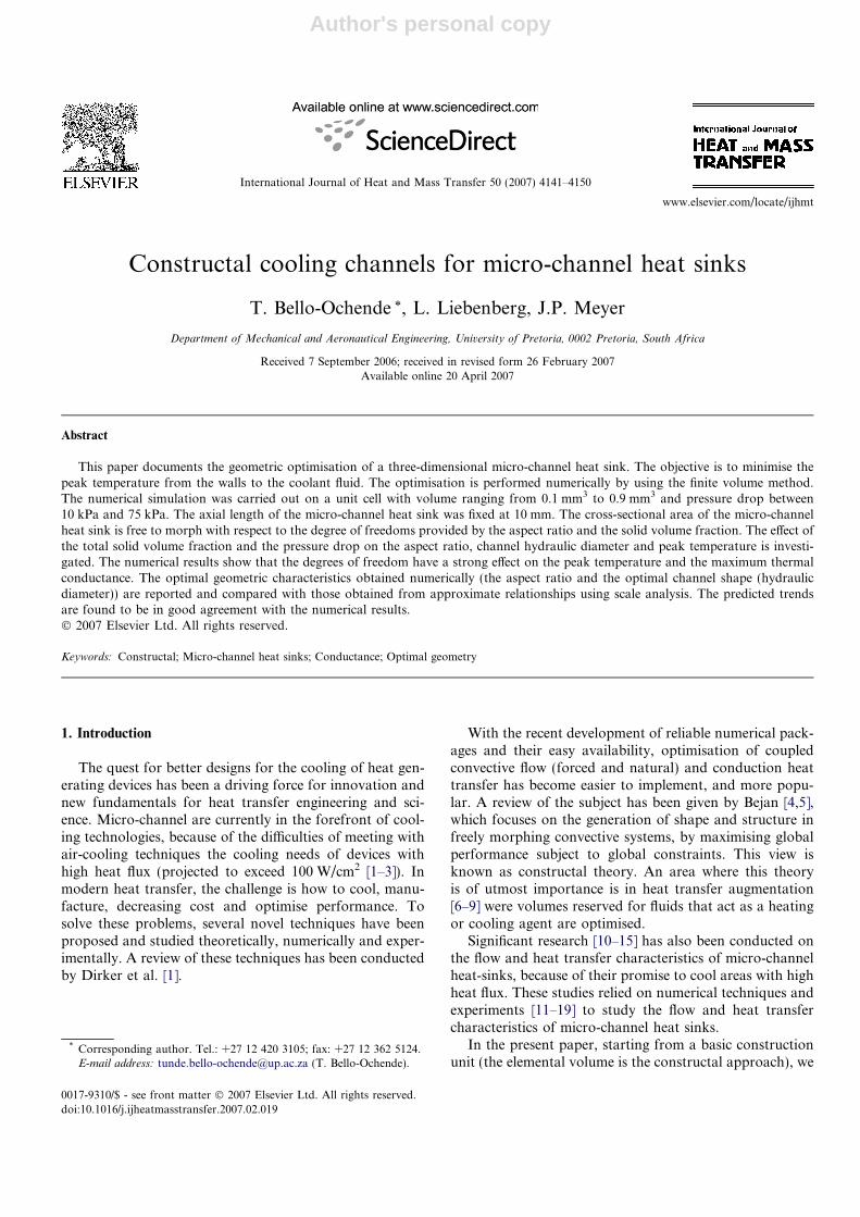
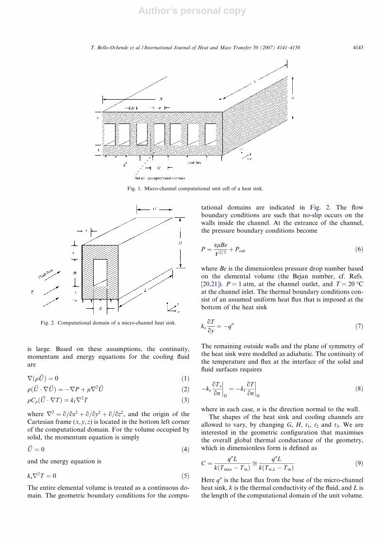
Fig. 1 shows a drawing of the physical model and thecomputational domain for a micro-channel heat sink. Heatis supplied to a highly conductive silicon substrate withknown thermal conductivity from a heating area locatedat the bottom of the heat sink. The heat is then removedby a fluid flowing through a number of micro-channels.Using the advantage of symmetry, we select for analysisan elemental volume (unit cell) consisting of a micro-chan-nel and the surrounding solid, as is shown in Fig. 2. Thiswork was based on the model of Qu and Mudawar [12]and Kawano et al. [17].
The heat transfer in the elemental volume is a conjugateproblem that combines heat conduction in the solid and
convective heat transfer in the liquid. The two heat transfermechanisms are coupled through the continuity of temper-ature and heat flux at the interface between the fluid andthe solid. The fluid with inlet temperature Tin is driventhrough the micro-channel by a fixed pressure differenceDP ¼ P ðz ¼ 0Þ � P ðz ¼ LÞ, which is maintained betweenthe channel inlet and outlet. The objective of the followinganalysis is to determine the heat transfer characteristicsfor a given micro-channel, and the best possible configura-tion (L, t1/t2, t2/t3, H/G) that corresponds to the maximalglobal thermal conductance, or global minimal thermalresistance.
The following assumptions were made to model the heattransfer and fluid flow in the elemental volume: the hydrau-lic diameter of the micro-channel under analysis is greaterthan 10 lm; for water, the continuum regime applies hencethe Navier–Stokes and Fourier equations can still be usedto describe the transport processes; steady-state conditionsfor flow and heat transfer; incompressible flow; the proper-ties of the solid and fluid are constant; and the heat transferdue to radiation and natural convection is negligible. Italso assumed that the number of elemental micro-channels
Nomenclature
A channel cross-sectional areaBe Bejan number based on a unit volume,
DPV 2=3=alBeL Bejan number based on L, DPL2=alB channels widthC dimensionless global conductanceCp specific heat at constant pressureDh hydraulic diameterf friction factorG width of computational domain (Bþ t1)�h average heat transfer coefficientH heightHc channel heightk thermal conductivityL axial lengthn normalnum number of channelsP pressurePc perimeter of micro-channelPo Poiseuille number based on hydraulic diameterPr Prandtl numberq total heat transferq00 heat fluxR thermal resistanceReDh
Reynolds number based on hydraulic diameterReL Reynolds number based on LT temperatureTw,L exit temperatureTin inlet temperatureTmax maximum temperature
t1 half thickness of vertical solidt2 base thicknesst3 top thicknessU average velocity~U velocity vectorV volumeW heat sink widthx; y; z Cartesian coordinates
Greek symbolsa thermal diffusivityD differencel viscositym kinematic viscosityq density/ volume fraction of solid materials shear stressX interface between the solid and fluid
Subscripts
c channelf fluidh hydraulic diameterin inletmax maximummin minimumopt optimumout outlets solid
4142 T. Bello-Ochende et al. / International Journal of Heat and Mass Transfer 50 (2007) 4141–4150
Author's personal copy
is large. Based on these assumptions, the continuity,momentum and energy equations for the cooling fluidare
rðq~UÞ ¼ 0 ð1Þqð~U � r~UÞ ¼ �rP þ lr2~U ð2ÞqCpð~U � rT Þ ¼ kfr2T ð3Þ
where r2 ¼ o=ox2 þ o=oy2 þ o=oz2, and the origin of theCartesian frame (x,y,z) is located in the bottom left cornerof the computational domain. For the volume occupied bysolid, the momentum equation is simply
~U ¼ 0 ð4Þ
and the energy equation is
ksr2T ¼ 0 ð5Þ
The entire elemental volume is treated as a continuous do-main. The geometric boundary conditions for the compu-
tational domains are indicated in Fig. 2. The flowboundary conditions are such that no-slip occurs on thewalls inside the channel. At the entrance of the channel,the pressure boundary conditions become
P ¼ alBe
V 2=3þ P out ð6Þ
where Be is the dimensionless pressure drop number basedon the elemental volume (the Bejan number, cf. Refs.[20,21]). P = 1 atm, at the channel outlet, and T = 20 �Cat the channel inlet. The thermal boundary conditions con-sist of an assumed uniform heat flux that is imposed at thebottom of the heat sink
ks
oToy¼ �q00 ð7Þ
The remaining outside walls and the plane of symmetry ofthe heat sink were modelled as adiabatic. The continuity ofthe temperature and flux at the interface of the solid andfluid surfaces requires
�ksoT s
on
����X
¼ �kfoTon
����X
ð8Þ
where in each case, n is the direction normal to the wall.The shapes of the heat sink and cooling channels are
allowed to vary, by changing G, H, t1, t2 and t3. We areinterested in the geometric configuration that maximisesthe overall global thermal conductance of the geometry,which in dimensionless form is defined as
C ¼ q00LkðT max � T inÞ
ffi q00LkðT w;L � T inÞ
ð9Þ
Here q00 is the heat flux from the base of the micro-channelheat sink, k is the thermal conductivity of the fluid, and L isthe length of the computational domain of the unit volume.
Fig. 1. Micro-channel computational unit cell of a heat sink.
Fig. 2. Computational domain of a micro-channel heat sink.
T. Bello-Ochende et al. / International Journal of Heat and Mass Transfer 50 (2007) 4141–4150 4143
Author's personal copy
The global conductance C is a dimensionless way ofexpressing the ratio of the total heat transfer rate q dividedby the largest excess temperature (T w;L � T in) reached atany point in the micro-channel heat sink. The maximumtemperature is expected to occur in the exit plane of themicro-channel heat sink. The reciprocal of C is the dimen-sionless global thermal resistance.
3. Numerical method and code validation
The finite volume method was used to solve the continu-ity, momentum and energy equations. A detailed explana-tion is given in Patankar [22]. In the finite volume methodthe domain is divided into a number of control volumessuch that there is one control volume surrounding eachgrid point. The grid point is located in the centre of thecontrol volume. The governing equation is integrated overeach control volume to derive algebraic equations contain-ing a point value of the dependent variable at the gridpoint. The discretised equations express the conservationprinciple for a finite volume.
The second order upwind scheme was used to model thecombined convection–diffusion effect in the transport equa-tions. The resulting algebraic equations were solved using aline-by-line tri-diagonal matrix inversion algorithm. TheSIMPLE algorithm [22] was then applied to solve the cou-pled systems of equations.
Convergence is obtained when the residuals for the massand momentum equation are smaller than 10�4, and theresidual of the energy equation becomes less than 10�9.A grid independence test was carried out for the micro-channel heat sink with the dimension given in Table 1.Tests show that for a control volume with a mesh size of25 in the x-direction, 50 in the y-direction and 150 in thez-direction assures a grid independent solution in whichthe maximum thermal resistance changes less than 2.5%when the mesh is sequentially doubled. This mesh alsoguaranteed that the numerical results obtained in this workare comparable with predictions and data obtained fromexperimental and numerical work.
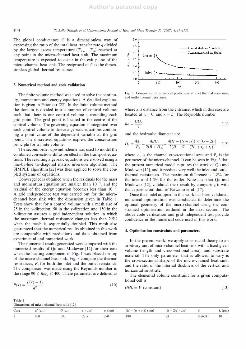
The numerical results generated were compared with thenumerical results of Qu and Mudawar [12] for their casewhen the heating component in Fig. 1 was placed on topof the micro-channel heat sink. Fig. 3 compare the thermalresistances, R, for both the inlet and the outlet resistance.The comparison was made using the Reynolds number inthe range 90 6 ReDh
6 400. These parameter are defined as
RðxÞ ¼ T ðxÞ � T 0
q00ð10Þ
where x is distance from the entrance, which in this case arelocated at x = 0, and x ¼ L. The Reynolds number
Re ¼ UDh
mð11Þ
and the hydraulic diameter are
Dh �4Ac
P c
¼ 4BH c
2ðBþ H cÞ¼ 4ðH � ðt2 þ t2ÞÞ � ðG� 2t1Þ
2ðH þ G� ð2t1 þ t2 þ t3ÞÞð12Þ
where Ac is the channel cross-sectional area and Pc is theperimeter of the micro-channel. It can be seen in Fig. 3 thatthe present numerical model captures the work of Qu andMudawar [12], and it predicts very well the inlet and outletthermal resistances. The maximum difference is 1.8% forthe inlet and 1.5% for the outlet. Note also that Qu andMudawar [12], validated their result by comparing it withthe experimental data of Kawano et al. [17].
Once the model adopted in this work has been validated,numerical optimisation was conducted to determine theoptimal geometry of the micro-channel using the con-strained optimisation outlined in the next section. Theabove code verification and grid-independent test provideconfidence in the numerical code used in this work.
4. Optimisation constraints and parameters
In the present work, we apply constructal theory to anarbitrary unit of micro-channel heat sink with a fixed givenvolume (length and cross-sectional area), and substratematerial. The only parameter that is allowed to vary isthe cross-sectional shape of the micro-channel heat sink,and the ratio of the internal thickness of the vertical andhorizontal substrate.
The elemental volume constraint for a given computa-tional cell is
GHL ¼ V ðconstantÞ ð13Þ
Table 1Dimensions of micro-channel heat sink [12]
Case H (lm) G (lm) t1 (lm) t2 (lm) ðH � ðt2 þ t3ÞÞ (lm) (G� 2t1Þ (lm) / L (lm)
1 900 100 22.5 270 180 28 0.6638 10
Fig. 3. Comparison of numerical predictions at inlet thermal resistance,and outlet thermal resistance.
4144 T. Bello-Ochende et al. / International Journal of Heat and Mass Transfer 50 (2007) 4141–4150

Author's personal copy
and the volume of the solid substrate is
2Ht1Lþ ðG� 2t1ÞLt2 þ ðG� 2t1Þt3L ¼ V s ðconstantÞ ð14Þ
For a fixed length we have
GH ¼ VL¼ A ðconstantÞ ð15Þ
The volume of the micro-channel is therefore
V f ¼ V � V s ðconstantÞ ð16Þ
Eq. (14) can also be expressed in terms of the solid volumefraction, / ¼ V s=V ¼ As=A. Eqs. (14)–(16) were solvedsimultaneously for t1, t2 and t3, such that for any changesin the assumed thickness and geometric parameters, the as-pect ratios (t1/t2, t2/t3, H/G and /), the total volume, andvolume of solid substrate remain fixed. The volume re-mains fixed, the cross-sectional shapes of the micro-channelheat sink change in such a way that the solid substrate con-ducts the heat from the base such that the thermal resis-tance is minimised. The total number of micro-channelsin the micro-channel heat sink arrangement is obtainedfrom
num ¼ WBþ 2t1
ð17Þ
for a fixed total width, W.
5. Scale analysis and the intersection of asymptotes method
In this section, we present the use of a scaling argumentto predict the optimal channel geometry that minimises theglobal thermal resistance or the maximum global thermalconductance. The following assumptions are madethroughout the analysis: uniform flow distribution (equalflow in all the channels, constant cross-sectional area ofthe channels, and no inlet or exit plenum losses), the Pra-ndtl number range Pr > 0.5, negligible axial conduction,and the thermal conductivity of the solid substrate is muchgreater than that of the fluid. The existence of an optimalarrangement can be expected based on the trade-off dem-onstrated in the forced convection cooling of electronicspackages [8], and the method outlined by Muzychka [23].To determine the optimal channel dimensions we use themethod of intersections of asymptotes [7] for a unitmicro-channel as shown in Fig. 2. The global thermal con-ductance scales are evaluated in two extreme limits (smallchannel and large channels).
The method of intersections of the asymptotes outlinedby Muzychka [23] is used for determining the optimal ductshape. In the limit of small channels, the micro-channellength is covered mainly by fully developed flow and theflow is mainly Hagen–Poiseuille flow, the maximum tem-perature difference occurs between the outlet wall and theinlet temperature of the micro-channel heat sink. Assumingthe total heat generated at the base of the micro-channel isconducted and deposited as heat current at the inner sur-
face of the duct, the total heat transfer for a small ductfor fully developed flow gives
qsmall ¼ qAcUCpðT w;L � T inÞ ð18Þ
where U is the average velocity defined as
U ¼ AcDPDh
lP cLPoð19Þ
Po is the Poiseuille number based on hydraulic diameter,and Po ¼ fReDh
=2, therefore Eq. (18) reduces to
qsmall ¼ ðT w;L � T inÞqCpA2
cDPDh
lP cLPoð20Þ
The resulting expression for the total heat transfer is
qsmall ¼ kfðT w;L � T inÞA2
c
P c
Dh
L3
BeL
Poð21Þ
BeL is the Bejan number based on the channel length(BeL ¼ DPL2=al). The resulting expression for dimension-less global thermal conductance is
Csmall ¼ 0:25D2
h
LV 1=3
BePo
ð22Þ
The above expression shows that for small channel thedimensionless thermal conductance, Csmall is directly pro-portional to D2
h.In the opposite extreme, for large channels the flow is
essentially a boundary layer flow, and the maximum tem-perature difference across the thermal boundary layer isgiven by
qlarge ¼ �hLP cðT w;L � T inÞ ð23Þ�hL ffi 0:453kfPr1=3Re1=2
L ð0:5 < Pr < 10Þ ð24Þ
where
ReL ¼U1L
mð25Þ
The core velocity U1 serves as the free stream velocity forthe boundary layer. This velocity follows from the longitu-dinal pressure force balance on the control volumeinscribed inside one channel
DPAc ffi �sP cL ð26Þ
where �s is the mean wall shear stress is obtained from theboundary layer solution referenced over the length L
�s ¼ 0:664qU 21Re�1=2
L ð27Þ
Finally, combining Eqs. (25)–(27) yields
ReL ¼DPAcL
0:664qm2P c
� �2=3
ð28Þ
Putting Eq. (28) into Eq. (23), the total heat transferbecomes
qlarge ffi 0:5192kfðT w;L � T inÞDPAcP 2
cLqm2
� �1=3
Pr1=3 ð29Þ
T. Bello-Ochende et al. / International Journal of Heat and Mass Transfer 50 (2007) 4141–4150 4145
Author's personal copy
or in terms of BeL,
qlarge ffi 0:5192kfðT w;L � T inÞAcP 2
c
L
� �1=3
Be1=3L ð30Þ
In dimensionless form the global thermal conductancebecomes
Clarge ¼ 1:31V 1=9L1=3
D2=3h
Be1=3 ð31Þ
The above expression shows that, Clarge is directly propor-
tional to D�2=3h . The dimensionless version of the equations
obtained in the two limits, Eqs. (22) and (31), are reportedin Fig. 4. The optimal channel shape can be approximatedas the Dh value where the two curve intersect
Dh;opt � 1:86ðL3V Þ1=6Po3=8Be�1=4 ð32ÞPo can be approximated using a single-term approximationfor the Poiseuille number [24,25] for H c > B
Po ¼ 12
1þ BH c
� �2
1� 192p5
BH c
tanh p2
H c
B
� �h i ð33Þ
Eq. (32) can be introduced in Eq. (22) or Eq. (31) todetermine the maximum dimensionless global thermalconductance
Cmax; theoretical � 0:864Be1=2
Po1=4ð34Þ
As shown above, the intersection of asymptotes methodand scale analysis are powerful tools that allows engineersand scientists to estimate trends and optimal configurations(see Ref. [7]), preface. It is important though to understandthe limits of the theoretical results obtained from Eqs. (32)and (34). There are only rough estimates of the results andthe trends. They have to be compared with the resultsobtained from numerical optimisation. The above relationsare valid for large Be. According to Knight et al. [13], therealistic dimensionless pressure drop number throughmicro-chips should be typically in the range of 108–1012.
6. Results: Optimal geometry for micro-channel heat sinks
In the preceding section an approximate method wasused to determine the optimal channel shape that mini-mises the global thermal conductance. A series of numeri-cal optimisations and calculations are conducted in thissection, and the results are presented in order to showthe effects of pressure drop, solid materials and the effectof the external aspect ratio for a fixed set of internal aspectratios (the ratio of base solid thickness to vertical thick-ness) on the optimal micro-channel geometry. Some impor-tant fluid flow and heat transfer parameters that areemployed in this study are summarised in Table 1. Thethermo-physical properties of water used in this study arebased on water at 20 �C. The volume of the micro-channelis fixed and it is based on the data given by Qu and Muda-war [12]. The thermal conductivity of the solid substrate(silicon) was taken to be 148 W/m K. The applied heat fluxat the bottom of the micro-channel was fixed at 100 W/cm2. We seek to determine the best geometry that mini-mises the maximum excess temperature, Tmax or the overallglobal conductance.
The micro-channel heat sink has five degrees of freedom,L, H/G, t1/t2, t2/t3 and /. For this study three degrees of free-dom was fixed L, t1/t2 and t2/t3 while the other two wereallowed to vary with the assumed pressure drop. In the firststage of the optimisation, we fixed the internal structure ofthe micro-channel by setting (t1=t2 ¼ 0:08, t2=t3 ¼ 1 and/ ¼ 0:8). The total volume of the unit micro-channel wasset in the range 0.01 mm3
6 V 6 0.9 mm3, the axial lengthof the micro-channel was fixed at 10 mm, and a unit cross-sectional area varies from 0.01 to 0.09 mm2. The micro-channel heat sink is expected to occupy a total base surfacearea of 10 mm � 10 mm.
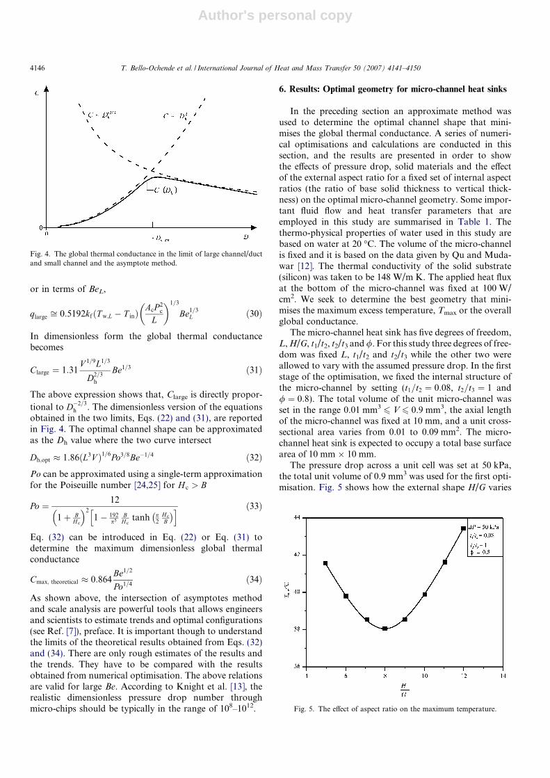
The pressure drop across a unit cell was set at 50 kPa,the total unit volume of 0.9 mm3 was used for the first opti-misation. Fig. 5 shows how the external shape H/G varies
Fig. 4. The global thermal conductance in the limit of large channel/ductand small channel and the asymptote method.
Fig. 5. The effect of aspect ratio on the maximum temperature.
4146 T. Bello-Ochende et al. / International Journal of Heat and Mass Transfer 50 (2007) 4141–4150
Author's personal copy
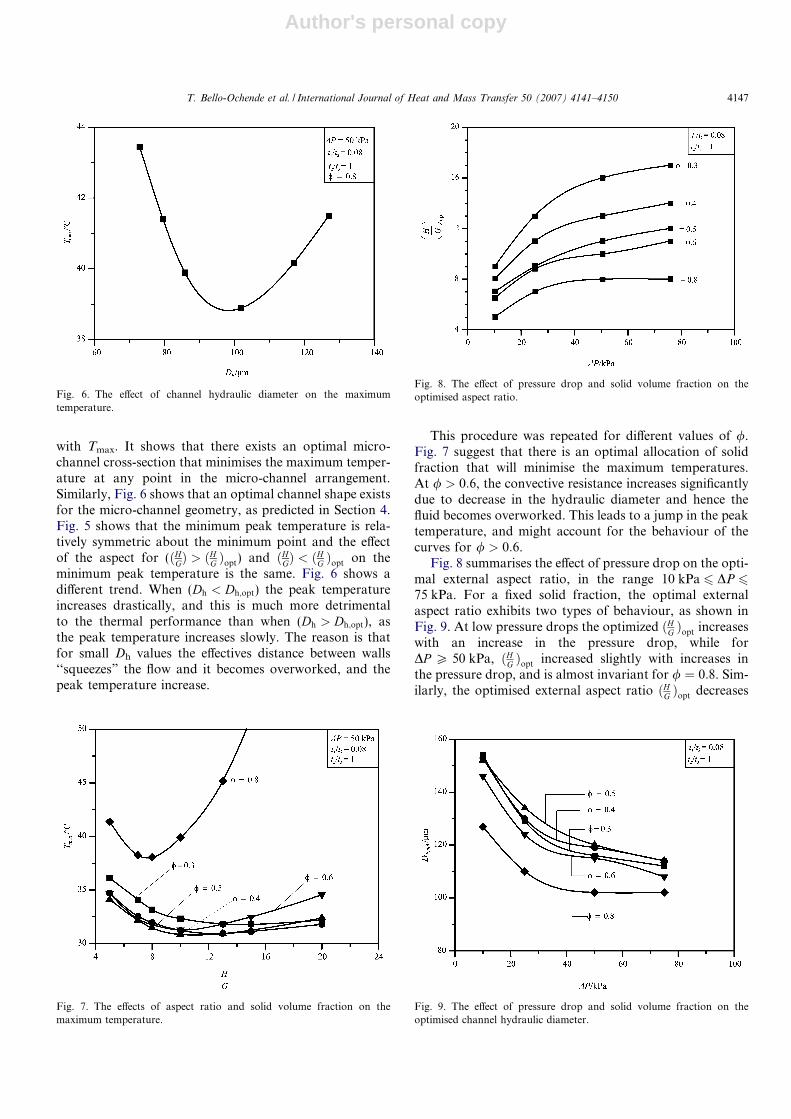
with Tmax. It shows that there exists an optimal micro-channel cross-section that minimises the maximum temper-ature at any point in the micro-channel arrangement.Similarly, Fig. 6 shows that an optimal channel shape existsfor the micro-channel geometry, as predicted in Section 4.Fig. 5 shows that the minimum peak temperature is rela-tively symmetric about the minimum point and the effectof the aspect for (ðHGÞ > ðHG Þopt) and ðHGÞ < ðHG Þopt on theminimum peak temperature is the same. Fig. 6 shows adifferent trend. When (Dh < Dh;opt) the peak temperatureincreases drastically, and this is much more detrimentalto the thermal performance than when (Dh > Dh;opt), asthe peak temperature increases slowly. The reason is thatfor small Dh values the effectives distance between walls‘‘squeezes” the flow and it becomes overworked, and thepeak temperature increase.
This procedure was repeated for different values of /.Fig. 7 suggest that there is an optimal allocation of solidfraction that will minimise the maximum temperatures.At / > 0:6, the convective resistance increases significantlydue to decrease in the hydraulic diameter and hence thefluid becomes overworked. This leads to a jump in the peaktemperature, and might account for the behaviour of thecurves for / > 0:6.
Fig. 8 summarises the effect of pressure drop on the opti-mal external aspect ratio, in the range 10 kPa 6 DP 675 kPa. For a fixed solid fraction, the optimal externalaspect ratio exhibits two types of behaviour, as shown inFig. 9. At low pressure drops the optimized ðHG Þopt increaseswith an increase in the pressure drop, while forDP P 50 kPa, ðHG Þopt increased slightly with increases inthe pressure drop, and is almost invariant for / ¼ 0:8. Sim-ilarly, the optimised external aspect ratio ðHG Þopt decreases
Fig. 6. The effect of channel hydraulic diameter on the maximumtemperature.
Fig. 7. The effects of aspect ratio and solid volume fraction on themaximum temperature.
Fig. 8. The effect of pressure drop and solid volume fraction on theoptimised aspect ratio.
Fig. 9. The effect of pressure drop and solid volume fraction on theoptimised channel hydraulic diameter.
T. Bello-Ochende et al. / International Journal of Heat and Mass Transfer 50 (2007) 4141–4150 4147
Author's personal copy
with an increase in the solid volume fraction for the rangeof geometric parameters used in this study. As the aspectratio increases the cross-sectional area of the micro-channelbecomes slender in the vertical direction and the value ofthe hydraulic diameter changes.
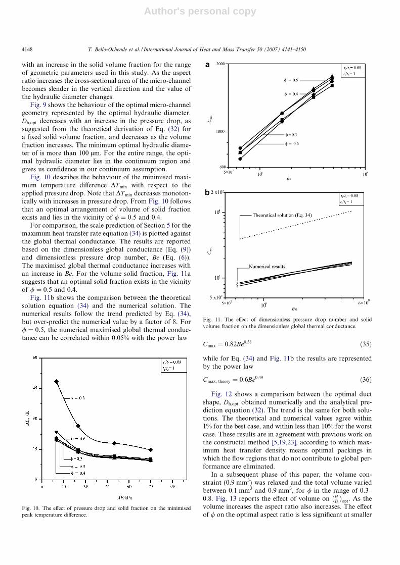
Fig. 9 shows the behaviour of the optimal micro-channelgeometry represented by the optimal hydraulic diameter.Dh;opt decreases with an increase in the pressure drop, assuggested from the theoretical derivation of Eq. (32) fora fixed solid volume fraction, and decreases as the volumefraction increases. The minimum optimal hydraulic diame-ter of is more than 100 lm. For the entire range, the opti-mal hydraulic diameter lies in the continuum region andgives us confidence in our continuum assumption.
Fig. 10 describes the behaviour of the minimised maxi-mum temperature difference DT min with respect to theapplied pressure drop. Note that DT min decreases monoton-ically with increases in pressure drop. From Fig. 10 followsthat an optimal arrangement of volume of solid fractionexists and lies in the vicinity of / ¼ 0:5 and 0.4.
For comparison, the scale prediction of Section 5 for themaximum heat transfer rate equation (34) is plotted againstthe global thermal conductance. The results are reportedbased on the dimensionless global conductance (Eq. (9))and dimensionless pressure drop number, Be (Eq. (6)).The maximised global thermal conductance increases withan increase in Be. For the volume solid fraction, Fig. 11asuggests that an optimal solid fraction exists in the vicinityof / ¼ 0:5 and 0.4.
Fig. 11b shows the comparison between the theoreticalsolution equation (34) and the numerical solution. Thenumerical results follow the trend predicted by Eq. (34),but over-predict the numerical value by a factor of 8. For/ ¼ 0:5, the numerical maximised global thermal conduc-tance can be correlated within 0.05% with the power law
Cmax ¼ 0:82Be0:38 ð35Þ
while for Eq. (34) and Fig. 11b the results are representedby the power law
Cmax; theory ¼ 0:6Be0:49 ð36Þ
Fig. 12 shows a comparison between the optimal ductshape, Dh;opt obtained numerically and the analytical pre-diction equation (32). The trend is the same for both solu-tions. The theoretical and numerical values agree within1% for the best case, and within less than 10% for the worstcase. These results are in agreement with previous work onthe constructal method [5,19,23], according to which max-imum heat transfer density means optimal packings inwhich the flow regions that do not contribute to global per-formance are eliminated.
In a subsequent phase of this paper, the volume con-straint (0.9 mm3) was relaxed and the total volume variedbetween 0.1 mm3 and 0.9 mm3, for / in the range of 0.3–0.8. Fig. 13 reports the effect of volume on ðHG Þopt. As thevolume increases the aspect ratio also increases. The effectof / on the optimal aspect ratio is less significant at smaller
Fig. 10. The effect of pressure drop and solid fraction on the minimisedpeak temperature difference.
Fig. 11. The effect of dimensionless pressure drop number and solidvolume fraction on the dimensionless global thermal conductance.
4148 T. Bello-Ochende et al. / International Journal of Heat and Mass Transfer 50 (2007) 4141–4150

Author's personal copy
volumes but this becomes pronounced as the volumeincreases. The aspect ratio decreases with increase in thesolid fraction. Similarly, Fig. 14 shows the effect of totalvolume on the optimal hydraulic diameter. The optimalhydraulic diameter increase as the volume increases, anddecreases to / ¼ 0:8.
The maximised peak temperature decrease with anincrease in the total volume as reported in Fig. 15. Atlow total volume, the behaviour of the minimised peaktemperature is distinct for various / (increases with /),but as the total volume increases the minimised peak tem-peratures coalesce for 0:3 6 / 6 0:6.
7. Conclusions
In this paper we showed numerically and theoreticallythat the global thermal conductance for a micro-channelheat sink can be maximised by optimising the aspect ratio,H/G, and therefore the channel hydraulic diameter for lam-inar forced-conjugate heat transfer. The numerical simula-tions, which were conducted in the range 10 kPa 6 DP 6
75 kPa, 0.1 mm36 V 6 0.9 mm3, show that the optimal
aspect ratio ðHG Þopt increases as the pressure difference(DP ) increases, for a fixed volume (V). An optimal alloca-tion of solid volume fraction exists in the / range from0.4 to 0.5. Numerical optimisation results further show thatthe optimal micro-channel shape (Dh;opt) and the minimisedpeak temperature (maximised global thermal conductance)are functions of the applied pressure difference and solidvolume fraction. Comparisons of the results obtainednumerically with approximate solutions based on scaleanalysis show excellent agreement for optimal micro-chan-nel dimensions. The approximate dimensionless globalthermal conductance predicts the trend obtained numeri-cally. It is expected that the conceptual design of micro-channel heat sinks using the constructal method will leadto better and faster design of micro-channel heat sinks with
Fig. 13. The effect of total micro-channel volume and solid volumefraction on the aspect ratio.
Fig. 14. The effect of total micro-channel heat sink volume and solidvolume fraction, on the optimal channel shape.
Fig. 15. The effect of total micro-channel heat sink volume and solidvolume fraction on the minimised temperature difference.Fig. 12. The optimal micro-channel shape (hydraulic diameter) for
maximum global conductance.
T. Bello-Ochende et al. / International Journal of Heat and Mass Transfer 50 (2007) 4141–4150 4149
Author's personal copy
improved performance and higher global thermalconductance.
Acknowledgments
Dr. Bello-Ochende acknowledges the support receivedfor the post-doctoral research from the University ofPretoria and the National Research Foundation of theRepublic of South Africa.
References
[1] J. Dirker, W. Liu, D. Van Wyk, J.P. Meyer, A.G. Malan, Embeddedsolid state heat extraction in integrated power electronic modules,IEEE Trans. Power Electron. 20 (3) (2005) 694–703.
[2] R. Webb, Next generation devices for electronic cooling with heatrejection to the air, J. Heat Transfer 127 (2005) 2–9.
[3] G. Hetsroni, A. Mosyak, E. Pogrebnyak, L.P. Yarin, Heat transfer inmicro-channels: comparison of experiments with theory and numer-ical results, Int. J. Heat Mass Transfer 48 (2005).
[4] A. Bejan, Shape and Structure from Engineering to Nature,Cambridge University Press, Cambridge, UK, 2000.
[5] A. Bejan, S. Lorente, Constructal theory of generation and config-uration in nature and engineering, J. Appl. Phys. 100 (2006) 041301.
[6] A. Bar-Cohen, W.M. Rohsenow, Thermally optimum spacing ofvertical natural convection cooled parallel plates, J. Heat Transfer 106(1984) 116–123.
[7] A. Bejan, Convection Heat Transfer, third ed., Wiley, New York, 2004.[8] T. Bello-Ochende, A. Bejan, Fitting the duct to the ‘‘body” of the
convective flow, Int. J. Heat Mass Transfer 46 (2006) 1693–1701.[9] A. Bejan, E. Sciubba, The optimal spacing for parallel plates cooled by
forced convection, Int. J. Heat Mass Transfer 35 (1992) 3259–3264.[10] D.B. Tuckerman, R.F.W. Pease, High-performance heat sinking for
VLSI, IEEE Electron. Dev. Lett. EDL-2 (1981) 126–129.[11] K.C. Toh, X.Y. Chen, J.C. Chai, Numerical computation of fluid
flow and heat transfer in microchannels, Int. J. Heat Mass Transfer 45(2002) 5133–5141.
[12] W. Qu, I. Mudawar, Analysis of three-dimensional heat transfer inmicro-channel heat sinks, Int. J. Heat Mass Transfer 45 (2002) 3973–3985.
[13] R.W. Knight, D.J. Hall, J.S. Goodling, C.J. Jaeger, Heat sinkoptimization with application to microchannels, IEEE Trans. Com-pon. Hybrids Manufact. Technol. 15 (5) (1992) 832–842.
[14] A.G. Fedorov, R. Viskanta, Three-dimensional conjugate heattransfer in the micro-channel heat sink for electronic packaging,Int. J. Heat Mass Transfer (2000) 399–415.
[15] J. Li, G.P. Peterson, P. Cheng, Three-dimensional analysis of heattransfer in a micro-heat sink with single phase flow, Int. J. Heat MassTransfer 47 (2004) 4215–4231.
[16] S.K.W. Tou, C.P. Tso, X. Zhang, 3-D numerical analysis of naturalconvective cooling of a 3 � 3 heater array in rectangular enclosures,Int. J. Heat Mass Transfer 44 (1999) 3231–3244.
[17] K. Kawano, K. Minikami, H. Iwasaki, M. Ishizuka, Micro channelheat exchanger for cooling electrical equipment, Application of HeatTransfer in Equipment Systems and Education ASME HTD – 361-3/PID-3 (1998) 173–180.
[18] K. Foli, T. Okabe, M. Olhofer, Y. Jin, B. Sendhoff, Optimization ofmicro heat exchanger: CFD analytical approach and multi-objectiveevolutionary algorithms, Int. J. Heat Mass Transfer 49 (2006) 1090–1099.
[19] M. Favre-Marinet, S. Le Person, A. Bejan, Maximum heat transferrate density in two-dimensional mini-channels and micro-channels,Microscale Thermophys. Eng. (2004) 225–237.
[20] S. Bhattacharjee, W.L. Grosshandler, The formation of wall jet near ahigh temperature wall under microgravity environment, ASME HTD96 (1988) 711–716.
[21] S. Petrescu, Comments on the optimal spacing of parallel platescooled by forced convection, Int. J. Heat Mass Transfer 37 (1994)1283.
[22] S.V. Patankar, Numerical Heat Transfer and Fluid flow, Hemisphere,New York, 1980.
[23] Y.S. Muzychka, Constructal design of forced convection cooledmicro-channel heat sinks and exchanger, In. J. Heat Mass Transfer 48(2005) 3119–3124.
[24] R.K. Shah, A.L. London, Laminar Flow Forced Convection inDucts, Academic Press, NY, 1978.
[25] A. Yilmaz, O. Buyukalaca, T. Yilmaz, Optimum shape and dimen-sions of channel for convective heat transfer in laminar flow atconstant wall temperature, Int. J. Heat Mass Transfer 43 (2000) 767–775.
4150 T. Bello-Ochende et al. / International Journal of Heat and Mass Transfer 50 (2007) 4141–4150
Copyright © 2022 FDOKUMEN