
Comparative analysis of single phase microchannel for heat ...
Upload
independentCategory
view
3download
0
International Journal of Thermal Sciences 48 (2009) 342–352www.elsevier.com/locate/ijts
Constructal tree-shaped microchannel networks for maximizingthe saturated critical heat flux
Rémi Revellin a,∗, John R. Thome b, Adrian Bejan c, Jocelyn Bonjour a
a Centre de Thermique de Lyon (CETHIL), UMR 5008 CNRS-INSA-Univ. Lyon 1, Bât. Sadi Carnot, INSA-Lyon, F-69621 Villeurbanne Cedex, Franceb École Polytechnique Fédérale de Lausanne, STI ISE LTCM, ME G1 464, Station 9, CH-1015 Lausanne, Switzerland
c Department of Mechanical Engineering and Materials Science, Duke University, Durham, NC 27708-0300, USA
Received 10 September 2007; received in revised form 27 May 2008; accepted 15 June 2008
Available online 29 July 2008
Abstract
A constructal tree-shaped microchannel network for maximizing the saturated critical heat flux in a disc-shaped planar body has been inves-tigated. n0 radial channels touch the center and np channels touch the periphery. Designs with no pairing level (n0 = np), one pairing level(2n0 = np) and two pairing levels (4n0 = np) have been studied. The fluid simulated is R-134a at a saturation temperature of Tsat = 30 ◦C withno inlet subcooling. The flow enters at the center and exits at the periphery. The theoretical CHF model of Revellin and Thome [R. Revellin, J.R.Thome, A theoretical model for the prediction of the critical heat flux in heated microchannels, Int. J. Heat Mass Transfer 51 (2008) 1216–1225],specially developed for micro and minichannels, has been modified and used for predicting the wall CHF of low pressure refrigerants flowing inmicrochannels. The constraints are the disc radius R and the total volume of ducts V . The degrees of freedom are n0, np and the mass flow rate m.In each case, the minimum global fluid flow resistance design has been adopted as proposed by Wechsatol et al. [W. Wechsatol, S. Lorente, A. Be-jan, Optimal tree-shaped networks for fluid flow in a disc-shaped body, Int. J. Heat Mass Transfer 45 (2002) 4911–4924]. Maximizing the baseCHF means increasing the number of central tubes for a given complexity. Furthermore, it is better to use a simple radial structure (with no pairinglevel) and 2n0 central tubes than a design with one pairing level and n0 central tubes. On one hand, simplified structures seem to be roughly betterfor maximizing the base CHF. On the other hand, coupling the base CHF and the pumping power leads to different conclusions. There exists anoptimal n0 and np to maximize the base CHF for each range of pumping power. For instance, for low pumping power, using radial ducts withoutpairing level is the best solution for dissipating high base CHF whereas for higher pumping power, a more complex design is beneficial withgreater np . In conclusion, the recommended complexity is modest (not maximal), and high complexity is not necessarily the best solution.© 2008 Elsevier Masson SAS. All rights reserved.
Keywords: Critical heat flux; Microchannel; Flow boiling; Refrigerant; Chip cooling; Constructal; Dendritic
1. Introduction
Cooling of microprocessors and power electronics becomean important issue in electronics. During the last decades var-ious ways have been investigated to dissipate high heat fluxes(up to 3000 kW/m2). Flow boiling in multi-microchannel evap-orators of low pressure refrigerants is one of the most promisingsolutions to dissipate such high heat fluxes. The upper opera-tional limit of a micro-evaporator cooling element is the crit-ical heat flux (CHF). It is the maximum heat flux that can be
* Corresponding author. Tel.: +33 4 72 43 83 46; fax: +33 4 72 43 88 11.E-mail address: [email protected] (R. Revellin).
1290-0729/$ – see front matter © 2008 Elsevier Masson SAS. All rights reserved.doi:10.1016/j.ijthermalsci.2008.06.009
dissipated by an evaporating two-phase flow without a largeexcursion in wall temperature. It refers to the replacement ofthe liquid being in contact with the heated surface with a va-por blanket. The thermal conductivity of the vapor is very lowcompared to that of the liquid, and the heat transfer coefficientdrops dramatically, resulting in the sudden increase of the sur-face temperature and possible failure of the cooled device.
The objective here is to combine constructal theory of Be-jan [3] to the CHF theory of Revellin and Thome [4] (a CHFmodel specially developed for flow boiling of refrigerants inmicro- and minichannels) in order to analyze the possible ben-efits for high heat flux cooling using boiling in microchannels.The Constructal Law states that for a finite-size flow system to

R. Revellin et al. / International Journal of Thermal Sciences 48 (2009) 342–352 343
Nomenclature
A cross sectional area . . . . . . . . . . . . . . . . . . . . . . . . m2
C complexitycp specific heat at constant pressure . . . . . . . . J/kg KCHF critical heat flux . . . . . . . . . . . . . . . . . . . . . . . . W/m2
dz element of discretization . . . . . . . . . . . . . . . . . . . . mD channel diameter . . . . . . . . . . . . . . . . . . . . . . . . . . . mg acceleration of gravity . . . . . . . . . . . . . . . . . . . m/s2
G mass flux . . . . . . . . . . . . . . . . . . . . . . . . . . . . kg/m2 shlv latent heat of vaporization . . . . . . . . . . . . . . . . . J/kgL length . . . . . . . . . . . . . . . . . . . . . . . . . . . . . . . . . . . . . mm mass flow . . . . . . . . . . . . . . . . . . . . . . . . . . . . . . . . kg/sn0 number of central channelsnp number of peripheral channelsp pressure . . . . . . . . . . . . . . . . . . . . . . . . . . . . . . . . . . . PaP perimeter of the channel . . . . . . . . . . . . . . . . . . . . . mq base heat flux . . . . . . . . . . . . . . . . . . . . . . . . . . W/m2
qα base heat flux of the sector α . . . . . . . . . . . . W/m2
qw wall heat flux . . . . . . . . . . . . . . . . . . . . . . . . . . W/m2
r radius of the vapor core . . . . . . . . . . . . . . . . . . . . . mR disc radius . . . . . . . . . . . . . . . . . . . . . . . . . . . . . . . . . mRe Reynolds numberT temperature . . . . . . . . . . . . . . . . . . . . . . . . . . . . . . . ◦Cu velocity . . . . . . . . . . . . . . . . . . . . . . . . . . . . . . . . . m/sV total channel flow volume . . . . . . . . . . . . . . . . . . . m3
We Weber numberx vapor quality
z length along channel from entrance . . . . . . . . . . . m
Greek letters
α angle . . . . . . . . . . . . . . . . . . . . . . . . . . . . . . . . . . . . . radβ angle . . . . . . . . . . . . . . . . . . . . . . . . . . . . . . . . . . . . . radγ angle . . . . . . . . . . . . . . . . . . . . . . . . . . . . . . . . . . . . . radΓ diameter ratioδ film thickness . . . . . . . . . . . . . . . . . . . . . . . . . . . . . µm� difference�δi height of the interfacial waves . . . . . . . . . . . . . . µmμ dynamic viscosity . . . . . . . . . . . . . . . . . . . . . . . . . Pa sξ CHF ratioρ density . . . . . . . . . . . . . . . . . . . . . . . . . . . . . . . . kg/m3
σ surface tension . . . . . . . . . . . . . . . . . . . . . . . . . . N/mτ shear stress . . . . . . . . . . . . . . . . . . . . . . . . . . . . . N/m2
Υ geometrical parameter
Subscripts
b baseint interfaciall liquidlo liquid onlymin minimumsat saturationsub subcoolingv vaporw wall
persist in time (to live), it must evolve in such a way that it pro-vides easier access to the imposed (global) currents that flowthrough it. This law states that if a system is free to morph un-der global constraints, the better flow architecture is the one thatminimizes the global flow resistances, or maximizes the globalflow access [5].
One of the most widely used empirical methods developedfor predicting saturated CHF in a single channel is the Kattoand Ohno [6] correlation. For most regimes, they found a linearrise in CHF with increasing liquid subcooling. For normal re-frigerants their method is applicable only down to about 3.0 mmchannels. Katto [7] also proposed a general correlation for pre-dicting CHF of forced convection boiling in uniformly heatedrectangular channels fed with subcooled liquid. They concludedthat this CHF is nearly equal to the CHF of forced convectionboiling on heated plane surfaces in a parallel flow.
Bergles and Kandlikar [8] reviewed the existing studies oncritical heat flux in microchannels. They concluded at the timeof their review that single-tube CHF data were not availablefor microchannels. For the case of parallel multichannels theynoted that all the available CHF data were taken under unsta-ble conditions. The critical condition in that case was the re-sult of an upstream compressible fluid instability in the parallelchannel, namely the Ledinegg instability. As a result, the CHFvalues were lower than they would be if the channel flow werekept stable by an inlet restriction at the inlet of each channel.
Wojtan et al. [9] performed a series of single-tube tests todetermine the CHF in 0.509 and 0.790 mm internal diametermicrochannel tubes as a function of refrigerant mass velocity,heated length, saturation temperature and inlet liquid subcool-ing. The refrigerants tested were R-134a and R-245fa and theheated length of the microchannel was varied from 20 and70 mm. The results showed a strong dependence of CHF onmass velocity, heated length and microchannel diameter, butno measurable influence of small degree of liquid subcooling(2–15 ◦C) tested. The experimental results were compared tothe CHF single-channel correlation of Katto and Ohno [6] andthe multichannel correlation of Qu and Mudawar [10], showingthat the correlation of Katto–Ohno predicted their microchan-nel data better. The correlation of Qu and Mudawar exhibitedthe same trends as the CHF data but significantly overpredictedthem. Based on their experimental data, a new microscale ver-sion of the Katto–Ohno correlation for the prediction of wallCHF (qw) during saturated boiling in microchannels was pro-posed by Wojtan et al.:
qw
G · hlv
= 0.437
(ρv
ρl
)0.073
We−0.24lo
(L
D
)−0.72
(1)
with
Welo = G2 · L(2)
σ · ρl

344 R. Revellin et al. / International Journal of Thermal Sciences 48 (2009) 342–352
Revellin and Thome [4] have since developed a theoreticalmodel for predicting CHF in microchannels. The model isbased on the premise that CHF is reached when local dryout oc-curs during evaporation in annular flow in a uniformly heated,circular microchannel at the location where the height of theinterfacial waves reaches that of the annular film’s mean thick-ness. Many observations confirm that CHF in microchannelsoften occurs in annular flow, such has been observed in Wojtanet al. [9] and Revellin and Thome [11].
Agostini et al. [12] studied high heat flux flow boiling in asilicon multi-microchannel heat sink composed of 67 parallelchannels, 223 µm wide, 680 µm high and with 80 µm thick finsseparating the channels. The microchannel length was 20 mm.The footprint critical heat fluxes measured varied from 1120to 2500 kW/m2 and the wall critical heat fluxes from 219 to522 kW/m2 for mass velocities from 276 to 992 kg/m2 s. Theirdata were predicted well by the theoretical model of Revellinand Thome [4] and the correlation of Wojtan et al. [9].
Saturated critical heat flux has been studied extensively formacrochannels but much less for microchannels. The data basecurrently available for flow boiling of low pressure refrigerantsin microchannels is sparse. Different correlations exist for pre-dicting the CHF in microchannels. Use of correlations has theadvantage of being simple. However, correlations are limited intheir range of parameters for which they have been developedand the physics is usually not well defined. Using a numeri-cal model, such as that of Revellin and Thome, is slightly morecomplex but is based on physical phenomena and can be ex-pected to work for a large range of parameters. Moreover, anon-uniform heat flux can be applied as a boundary conditionin the model whereas correlations are restricted to the use ofuniform heat fluxes only.
Maximizing the critical heat flux also means optimizing thedesign of the evaporator with respect to pressure drop and heattransfer, an aspect not apparently addressed by any previousstudies except for Revellin and Thome [13] who proposed asolution for rectangular multi-microchannel cooling elements.Indeed, they proposed a premise of optimization by saying thatfor cooling of micro-processors, one design solution would beto place the fluid inlet at the mid-point along the length of themicrochannel element and have an exit at both ends. This wouldtake advantage of the fact that CHF increases with decreas-ing channel length and would allow a higher mass flux to beused while achieving the same two-phase pressure drop. Be-sides, different works have already been carried out on optimaltree-shaped networks for minimizing the flow and thermal re-sistances.
Wechsatol et al. [2] focused on the problem of how to de-sign a flow path with minimum overall resistance between onepoint (O) and many points located at the periphery of the circlecentered at O . They considered a laminar and fully developedsingle-phase flow. They showed that when the overall size ofthe structure grew, the best performance was provided by in-creasingly more complex structures. Furthermore, as the bestdesigns become more complex, the difference between succes-sive designs becomes small.
Wechsatol et al. [14] also developed the optimal tree-shapedflow paths for cooling a disc-shaped body by convection. Theconstraints were the disc size and the total volume occupied bythe ducts. The single-phase flow was assumed to be hydrody-namically and thermally fully developed. Minimizing the over-all thermal resistance lead to the use of a radial structure, notdendrites. Minimizing the pumping power consumption resultsin the use of dendrite structures. They concluded that increasingcomplexity is the route to higher thermal and fluid-flow perfor-mance in the limit of decreasing scales.
Optimizing a tree-shaped disc structure to maximize the crit-ical heat flux is the current objective using an evaporating two-phase flow in microchannels applied to electronic componentcooling. Minimizing the pumping power is also an importantissue. The model of Revellin and Thome [4] is modified andused here to achieve this goal. The CHF model is described be-low. Then the CHF model is applied to different geometries.There has been only few studies on applying constructal theoryto two-phase heat transfer and none to CHF. Hence, numerousassumptions are made in order to make this first effort.
2. Critical heat flux model
The theoretical model of Revellin and Thome [4] has beenused here for the prediction of the maximum mean heat fluxalong the microchannel (qw) taking into account a uniform ax-ial heat flux. It is based on the dryout mechanism of the liquidfilm during evaporation in annular flow for refrigerants flowingat stable conditions in heated circular microchannels. Many ob-servations confirm that CHF in microchannels occurs in annularflow, such has been observed in Wojtan et al. [9] and Revellinand Thome [11]. It is assumed in this model that the mecha-nism of dryout occurs when the average liquid film is greaterthan 0 (δl > 0) if the interfacial waves are large enough to havetheir trough in contact with the wall. In such a situation, the va-por quality x is lower than unity. Neglecting any entrainment ofliquid in the gas core and any potentially significant conductioneffects in the wall, the model takes into account the conserva-tion of mass and momentum, an energy balance with the wallin a one-dimensional finite volume model and the height of theinterfacial waves (�δi ) is predicted using an empirical expres-sion. This model is briefly described below.
Consider an annular flow of mass flux G in a microchannelof length L, diameter D and inner perimeter of P = πD, whereul and uv are the liquid and vapor velocities, ρl is the liquiddensity and ρv is the vapor density, pl and pv are the liquid andvapor pressures and hlv is the latent heat of vaporization. Thecontrol volume is presented in Fig. 1. The first two equationsare obtained from the conservation of mass and energy:
d(Alul)
dzdz = − qwP
hlvρl
dz (3)
d(Avuv)
dzdz = qwP
hlvρv
dz (4)
The conservation of momentum gives two additional equa-tions:

R. Revellin et al. / International Journal of Thermal Sciences 48 (2009) 342–352 345
Fig. 1. Control volume of the model.
ρl
d(Alu2l )
dzdz = −Al
dpl
dzdz + Aint|τlv| − Alw|τlw| (5)
ρv
d(Avu2v)
dzdz = −Av
dpv
dzdz − Aint|τvl | (6)
where Al = π((D/2)2 − r2), Av = πr2 and Aint = π√
2 ×(2r +dz)dz (assuming that dz has the same order of magnitudeas dr) are only function of r , the radius of the vapor core. Theshear stress τvl is obtained from the following equations:
τlv = 1
2Cf ρvu
2v where
Cf = 16
Rev
for Rev = 2ρvuvr
μv
< 2300
Cf = 0.078 Re−0.25v for Rev � 2300 (7)
The shear stress τlw is expressed by the following relations:
τlw = 1
2Cf ρlu
2l where
Cf = 16
Rel
for Rel = 2ρlul(D/2 − r)
μl
< 2300
Cf = 0.078 Re−0.25l for Rel � 2300 (8)
The system is closed by the Laplace–Young equation for thepressure difference across the curved interface of the annularliquid film:
dpv
dz− dpl
dz= d
dz
(σ
r
)(9)
with σ the surface tension.The flow at the inlet at z = 0 is assumed to be saturated liq-
uid. The system of 5 non-linear differential equations is solvedusing the fourth order Runge–Kutta method with the followingboundary conditions:
r|z=0 = rmin
uv|z=0 = G
ρl
ul |z=0 = G
ρl
pv|z=0 = psat
pl |z=0 = psat − σ
rmin(10)
The value of the initial radius was chosen according to Revellinand Thome [4]. The value has been set to rmin = 0.05D.
The wall heat flux is determined by a trial-and-error processto solve for an annular liquid film thickness equal the heightof the interfacial waves (δl = �δi ). Based on the slip ratio andthe Kelvin–Helmholtz critical wavelength (assuming the filmthickness to be proportional to the critical wavelength of theinterfacial waves), the critical film thickness is given by the fol-lowing expression:
�δi = 0.15
(D
2
)(uv
ul
)−3/7((ρl − ρv)g(D/2)2
σ
)−1/7
(11)
with g the acceleration of gravity.When the equality δl = �δi is satisfied anywhere along the
microchannel, CHF is reached. The adjusted constant and ex-ponents were determined from a data base including 3 differentfluids (R-134a, R-245fa and R-113), 3 different diameters (0.5,0.8 and 3.15 mm) from experiments performed in two differentlaboratories [9,10].
Furthermore, this model predicts the data for circular andrectangular multi-microchannel test sections of Bowers andMudawar [15] for R-113, and Agostini et al. [12] for R-236fataken in a collaborative project at IBM (Switzerland) and Parkand Thome for R-245fa. Agostini et al. and Park and Thomeused small orifices at the inlet of each channel in order to re-duce flow oscillations. The comparison between the presentmodel and the data base (136 data) covering 4 different fluidsand 7 different geometries (comprising single-microchannelsand multi-circular and multi-rectangular microchannels) takenin four different laboratories is very good, predicting 91% ofthe data within ±20%. The mean absolute error is 10%. In thedata base, the mass flux varied between 20 and 1533 kg/m2 sfor diameters ranging from 0.215 to 3.1 mm.
It is assumed here that local axial conduction effects are neg-ligible. Such effects can be simulated on a case by case basis bycoupling the present model with a finite element heat conduc-tion solver to account for the wall material and its thickness.
Fig. 2 shows the evolution of the radius of the vapor core(δl) and the critical film thickness (�δi ) along a microchannel.CHF occurs at the outlet of the microchannel when δl = �δi .
3. Radial flow pattern
The radial flow pattern is a simple structure without pairingwith as shown in Fig. 3. n0 channels touch the center and np =n0 channels touch the periphery. The complexity is defined as:
C = ln(np/n0)
ln(2)(12)
Here the complexity is 0. The flow enters at the center with amass flow rate m and exits at the periphery (m0 = m/n0). Thisstructure consists of a disc of radius R with its thickness ofthe order of the diameter of the channels. The disc is heated atthe bottom surface with a uniform heat flux q provided by an

346 R. Revellin et al. / International Journal of Thermal Sciences 48 (2009) 342–352
Fig. 2. Evolution of the radius of the vapor core and the critical film thicknessalong a microchannel with dryout a the outlet.
Fig. 3. Schematic of a radial flow pattern. n0 = np .
electronic component, for example. Losses are neglected andthe first law of thermodynamics is applied to one sector of an-gle α = 2π/n0. The heat flux applied to the base of the sector(qα = q) is conducted uniformly toward the channel (the disk isassumed to have an infinite thermal conductivity), so we get:
qw = qα
2R
n0D(13)
where qw is the wall CHF calculated with the theoretical model.The degrees of freedom are four: R, V , n0 (or np) and m. Thefirst constraint is the disc radius R and the second constraint isthe constant volume of the channels defined as:
V = n0RπD2
4(14)
The previous relation will fix the diameter only if n0 is known.The remaining degrees of freedom are n0 and m.
Fig. 4. Base CHF results without level pairing (radial design).
During the simulations, care was taken to stay in the domainof validity of the model, i.e. under the conditions for which themodel has been experimentally validated (Section 2). The discradius was fixed at 20 mm for the entire study and the differ-ent designs. Furthermore, the total volume of the channels V
has been chosen to be close to the total volume of channels ofAgostini et al. [12], i.e. 0.154 cm3. The fluid used is R-134a ata saturation temperature of Tsat = 30 ◦C without any inlet sub-cooling.
Fig. 4(a) shows the evolution of the base critical heat flux (qα
or q) as a function of the mass flow rate ranging from 0.25 to4.25 g/s for different values of n0 (from 3 to 48). The higher themass flow rate, the higher is qα , as mentioned by Revellin andThome [4]. For m = 4 g/s, passing from n0 = 3 to 48, multi-plies the base CHF by 2. Furthermore, the higher n0, the higheris qα . According to Eq. (14), D varies like n
−1/20 and based on
Eq. (13), qα increases like n1/20 qw . Considering the correlation
of Wojtan et al. (Eq. (1)) that predicts the wall CHF of refriger-

R. Revellin et al. / International Journal of Thermal Sciences 48 (2009) 342–352 347
ants in microchannels, according to this correlation, qw variesas D0.72 because G remains constant regardless of the value ofn0 (according to Eq. (14), G = mR/V ). As a result, qα is pro-portional to n0.14
0 . In conclusion, we see that the increase of n0leads to an increase of qα .
The present model gives also an approximate idea of thepressure drop value because it includes the calculation of thepressure gradient along the channel. The result is an approxi-mation as it takes into account only the annular flow regime.Nevertheless, it must be recalled that this is the main flowregime encountered along the channel in case of high heat flux.This pressure drop calculation has been experimentally vali-dated during smooth annular regime [4] but does not accountfor the magnifying effect of the interfacial waves. From an en-gineering point of view, it is useful to know either the pressuredrop or the pumping power required by the system:
W = m�P
ρl
(15)
The base CHF versus the pumping power is presented inFig. 4(b). For a constant pumping power, e.g., 0.005 W, it ispreferable to work with a greater number of channels to in-crease the base CHF. However, it can be noted that there is nodifference in the results for n0 = 24 and n0 = 48. For a pump-ing power of 10−4 W it is better to use n0 = 3 ducts whereasfor a pumping power of 5 × 10⁻⁴ W, n0 = 6 is better. Anotherway to use such a graph is to consider that a fixed value of CHFis prescribed (250 kW/m2 at the base, in the following). In thatsituation, what would be the best configuration to minimize thepumping power? The answer is n0 = 24 or n0 = 48.
We have assumed earlier that the heat flux applied to thebase of the sector was conducted uniformly toward the channelassuming an infinite thermal conductivity. What if the wall heatflux is not uniformly shared out but radially distributed? Theradial wall heat flux would be expressed as:
dqw = qα
(2π/n0)r dr
πD dr= qα
2r
n0D(16)
with r the radial abscissa also corresponding to z, the lengthalong the channel from entrance. The closer to the periphery,the higher the wall heat flux.
Fig. 5 shows the base CHF versus the mass flow rate and thepumping power for a radial distribution of the wall heat flux.Comparing with Fig. 4, a shift is observed. Indeed, the baseCHF results for a radial heat flux distribution are lower thanthose obtained for a uniform heat flux. Nevertheless, the trendsare identical and the general conclusions are not different. Thus,for a question of simplicity, a uniform wall heat flux was usedfor the rest of the study.
In conclusion, we can say that to aim for the highest CHFfor a constant mass flow rate leads to an increase in n0. Nev-ertheless, if we want to maximize the base CHF and minimizethe pumping power, a more accurate study has to be performed.Furthermore, for the sake of simplicity, the inlet quality was al-ways kept constant at x = 0. If the inlet condition is different,with a vapor quality greater than 0, the problem of flow maldis-tribution should be treated.
Fig. 5. Base CHF results without level pairing (radial design) for a radial wallheat flux distribution.
4. One pairing level
More complex structures are also studied here in order toevaluate the best configuration that would maximize the baseCHF (C = 1). One pairing level is placed at the radial distanceL0 as shown in Fig. 6. n0 channels touch the center and np =2n0 channels touch the periphery. L0 and L1 are expressed asfunctions of the angles α and β (as indicated in Fig. 6):
L0 = R cos
(α
4
)− R
sin(α/4)
tan(β)(17)
L1 = Rsin(α/4)
sin(β)(18)
The pairing node between the branches of level 0 and 1 is crit-ical for the model. Knowledge of the vapor radius r , the vaporand liquid velocities (uv and ul) as well as the vapor and liquidpressures (pv and pl) is required at the beginning of each new

348 R. Revellin et al. / International Journal of Thermal Sciences 48 (2009) 342–352
Fig. 6. Schematic of one pairing level flow pattern. n0 = 3 and np = 6.
branch. For these, a conservation of void fraction is applied atthe pairing node and we get for the general case:
ε = Avi
Ai
= Avi+1
Ai+1(19)
here Avi = πr2i , Avi+1 = πr2
i+1, Ai = πD2i /4 and Ai+1 =
πD2i+1/4, so it comes
ri+1 = riDi+1
Di
= riΓ (20)
where Γ is the ratio between the diameters of two successivechannels.
Furthermore, the conservation of vapor quality at the pairingnode requires:
x = mvi
mi
= mvi+1
mi+1(21)
It is assumed that the mass flow rate is equally divided in eachlevel of branching i + 1 (mi = 2mi+1) so that mvi = 2mvi+1.
Furthermore, mvi = (ρvuvAv)i and mvi+1 = (ρvuvAv)i+1,we thus obtain:
uvi+1 = 1
2uviΓ
−2 (22)
By analogy, we get:
uli+1 = 1
2uliΓ
−2 (23)
The saturation pressure is assumed to be constant and equal tothe vapor pressure so that pvi = pvi+1 and pli+1 = pvi+1 −σ/ri+1 using the Laplace–Young equation. The pressure lossesdue to the entrance, exit and bifurcations are neglected. In viewof the high pressure drops along the microchannel, these singu-larities would be negligible in typical small-scale applications.Besides, the final conclusions would not be changed if the sin-gularities were taken into account, only a shift of the resultswould be observed.
Finally, the starting conditions used for the model at anypairing node are:
Fig. 7. Evolution of the radius of the vapor core and the critical film thicknessalong two successive microchannels with dryout at the outlet.
ri+1 = riΓ
uvi+1 = 1
2uviΓ
−2
uli+1 = 1
2uliΓ
−2
pvi+1 = pvi
pli+1 = pvi+1 − σ
ri+1(24)
As for the radial design, the heat flux applied to the base ofthe sector (qα = q) is conducted uniformly toward the channels(infinite thermal conductivity). Thus, the relation between thewall heat flux and the base heat flux is as follows:
qw = qα
R2
n0D0(L0 + 2Γ L1)(25)
Fig. 7 shows the evolution of the radius of the vapor core and thecritical film thickness along two successive diabatic channelsof length L0 and L1 for Γ < 1 and heated with a uniform heatflux qw . Dryout occurs at the outlet of the second channel whenδl = �δi .
4.1. Diameter ratio
The value of Γ varies between 0 and 1 as the diameter de-creases along the flow direction. Fig. 8 shows the influenceof Γ on the base CHF for n0 = 24, different mass flow ratesand a constant value of β (see next section) and V . WhenΓ increases, the base CHF increases. At each pairing node,Gi+1/Gi = Γ −2/2. As a result, when Γ <
√1/2, Gi+1 > Gi .
We see that increasing the mass flux at the pairing node reducesthe base CHF. For a value of Γ >
√1/2, the base CHF varies
slightly.To get a better idea of the influence of Γ on the base CHF,
let us consider the correlation of Wojtan et al. According toEq. (1), the wall CHF varies as G0.52D0.72. Based on Eq. (13),

R. Revellin et al. / International Journal of Thermal Sciences 48 (2009) 342–352 349
Fig. 8. Influence of the ratio between successive diameters (Γ ) for one pairinglevel design (n0 = 24).
the base CHF will vary as G0.52D1.72. The CHF is mainly con-trolled here by the first level of pairing as G0 and D0 do notvary significantly with Γ . Indeed, for Γ = 0.2, D0 = 0.667mm and G0 = 29.8 kg/m2 s and for Γ = 1, D0 = 0.603 mmand G0 = 36.5 kg/m2 s. As a result, for two different values ofΓ we obtain:
ξ = CHFΓ1
CHFΓ2
=(
Γ1
Γ2
)0.68
(26)
For Γ1 = 0.4 and Γ2 = 1, ξ = 0.54, whereas for Γ1 = 2−1/3 andΓ2 = 1, ξ = 1.17. These orders of magnitude are confirmed onFig. 8: for example, for a pumping power of 10−4 W, the CHFvalue obtained with Γ = 0.4 (35 kW/m2) is close to that ob-tained for Γ = 1 (70 kW/m2) multiplied by a factor 0.54. Thisapproximation gives an idea of the behavior of the base CHFwith Γ . The remaining question is: what is the best diameterratio to maximize the base CHF? Usually, in single phase flow,Murray’s law [3] is used (Γ = 2−1/3) because many studieshave shown that it was the optimal size step at each pairingnode to minimize global flow resistance. Here in two-phaseflow, this value is also valuable for maximizing the base CHFeven if it strongly competes with Γ = 1. For the rest of thestudy, Γ = 2−1/3 was used.
4.2. Minimum global flow resistance design
The degrees of freedom are: R, V , n0 (or np), m and β . Thedisc radius is still fixed to R and the total volume of channels isconstant and equal to:
V = n0πD20
4
(L0 + 2Γ 2L1
)(27)
As a result, for each value of n0, different geometries can be de-termined depending on β (or L0 according to Eq. (17)). Fig. 9shows the influence of L′
0 = L0/R on the base CHF for differ-ent mass flow rates. The base CHF reaches a minimum for 2
Fig. 9. Base CHF versus L′0 for a design with one pairing level and three mass
flow rates (n0 = 3 and np = 6).
and 4 g/s whereas for 1 g/s, the value of CHF decreases reg-ularly. The highest CHF is reached for L′
0 equals to 0. Thisvalue means that a radial structure without pairing level and 2n0channels will be more efficient to dissipate base heat flux thana more complex design with one level pairing and n0 centralchannels.
A value of β (or L′0) has to be defined at this stage to go fur-
ther in the study. In order to simplify the choice, the idea is torefer to literature and use the geometry that gives the minimumglobal flow resistance in single phase flow as it has been per-formed by Wechsatol et al. [2] so that β = 0.654 rad (37.5◦) isretained for the design with one level pairing.
Fig. 10(a) shows the influence of the mass flow rate and n0on the base CHF. As expected, the higher the mass flow rate,the higher is the base CHF. Furthermore, the greater the valueof n0 (or np), the higher is the base CHF. Passing from n0 = 3to 12 at m = 3 g/s, multiplies the base CHF by 50%. Base CHFcoupling with pumping power results gives Fig. 10(b). For W <
10−4 W, np = 3 is the best design to maximize qα whereas forW = 10−2 W, np = 24 or 48 is a better choice. The conclusionsare similar to those for the radial design without pairing. Theobjective of the highest CHF with the constraint of the lowestpumping power is not necessarily reached with a great numberof radial ducts.
5. Two pairing levels
A more complex tree-shaped microchannel networks hasalso been studied and refers to the 2 pairing level design(C = 2). Fig. 11 shows an example of this structure for n0 = 3and np = 12. As explained earlier, the heat flux applied to thebase of the sector (qα = q) is conducted uniformly toward thechannels. As a consequence, the relation between the wall heatflux and the base heat flux is as follows:
qw = qα
R2
2(28)
n0D0(L0 + 2Γ L1 + 4Γ L2)

350 R. Revellin et al. / International Journal of Thermal Sciences 48 (2009) 342–352
Fig. 10. Base CHF results for one level pairing in minimum global flow resis-tance design.
Fig. 11. Schematic of two pairing level flow pattern. n0 = 3 and np = 12.
Fig. 12. Base CHF results for two level pairings in minimum global flow resis-tance design.
The degrees of freedom are: R, V , n0 (or np), m, β and γ . Theconstraints are the disc radius and the total volume of channelsthat is constant and equal to:
V = n0πD20
4
(L0 + 2Γ 2L1 + 4Γ 4L2
)(29)
The design corresponds to the minimal global flow resistanceof Wechsatol et al. [2]. The values of β and γ are thus fixed.L0, L1 and L2 are given by the following relations:
L2 = Rsin(α/8)
sin(γ )(30)
L0 = [R cos(α/8) − L2 cos(γ )]Υ1 + Υ
(31)
with
Υ = cos(α/4) − sin(α/4)/ tan(β)
1 − cos(α/4) + sin(α/4)/ tan(β)
L1 = (L0 + x1)sin(α/4)
(32)
sin(β)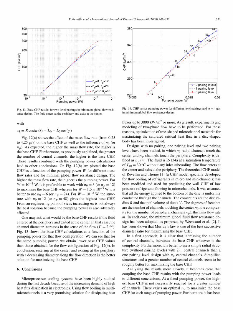
R. Revellin et al. / International Journal of Thermal Sciences 48 (2009) 342–352 351
Fig. 13. Base CHF results for two level pairings in minimum global flow resis-tance design. The fluid enters at the periphery and exits at the center.
with
x1 = R cos(α/8) − L0 − L2 cos(γ )
Fig. 12(a) shows the effect of the mass flow rate (from 0.25to 4.25 g/s) on the base CHF as well as the influence of n0 (ornp). As expected, the higher the mass flow rate, the higher isthe base CHF. Furthermore, as previously explained, the greaterthe number of central channels, the higher is the base CHF.These results combined with the pumping power calculationslead to other conclusions. On Fig. 12(b) are plotted the baseCHF as a function of the pumping power W for different massflow rates and for minimal global flow resistance design. Thehigher the mass flow rate, the higher is the pumping power. ForW = 10−4 W, it is preferable to work with n0 = 3 (or np = 12)to maximize the base CHF whereas for W = 1.5 × 10⁻³ W it isbetter to use n0 = 6 (or np = 24). For W = 10−2 W, the struc-ture with n0 = 12 (or np = 48) gives the highest base CHF.From an engineering point of view, increasing n0 is not alwaysthe best solution because the pumping power is also adverselyaffected.
One may ask what would be the base CHF results if the fluidentered at the periphery and exited at the center. In that case, thechannel diameter increases in the sense of the flow (Γ = 21/3).Fig. 13 shows the base CHF calculations as a function of thepumping power for that flow configuration. We can see that forthe same pumping power, we obtain lower base CHF valuesthan those obtained for the flow configuration of Fig. 12(b). Inconclusion, entering at the center and exiting at the peripherywith a decreasing diameter along the flow direction is the bettersolution for maximizing the base CHF.
6. Conclusions
Microprocessor cooling systems have been highly studiedduring the last decade because of the increasing demand of highheat flux dissipation in electronics. Using flow boiling in multi-microchannels is a very promising solution for dissipating heat
Fig. 14. CHF versus pumping power for different level pairings and m = 4 g/sin minimum global flow resistance design.
fluxes up to 3000 kW/m2 or more. As a result, experiments andmodeling of two-phase flow have to be performed. For thesereasons, optimization of tree-shaped microchannel networks formaximizing the saturated critical heat flux in a disc-shapedbody has been investigated.
Designs with no pairing, one pairing level and two pairinglevels have been studied, in which n0 radial channels touch thecenter and np channels touch the periphery. Complexity is de-fined as np/n0. The fluid is R-134a at a saturation temperatureof Tsat = 30 ◦C without any inlet subcooling. The flow enters atthe center and exits at the periphery. The theoretical CHF modelof Revellin and Thome [1] (a CHF model specially developedfor flow boiling of refrigerants in micro and minichannels) hasbeen modified and used for predicting the wall CHF of lowpressure refrigerants flowing in microchannels. It was assumedthat all the energy applied to the bottom of the disc is uniformlyconducted through the channels. The constraints are the disc ra-dius R and the total volume of ducts V . The degrees of freedomare the number of channels touching the center n0, the complex-ity (or the number of peripheral channels np), the mass flow ratem. In each case, the minimum global fluid flow resistance de-sign has been adopted, as proposed by Wechsatol et al. [2]. Ithas been shown that Murray’s law is one of the best successivediameter ratio for maximizing the base CHF.
In a first approach, it is clear that increasing the numberof central channels, increases the base CHF whatever is thecomplexity. Furthermore, it is better to use a simple radial struc-ture (without pairing levels) with 2n0 central channels than aone pairing level design with n0 central channels. Simplifiedstructures and a greater number of central channels seem to beroughly better for maximizing the base CHF.
Analyzing the results more closely, it becomes clear thatcoupling the base CHF results with the pumping power leadsto different conclusions. At a fixed pumping power, the high-est base CHF is not necessarily reached for a greater numberof channels. There exists an optimal n0 to maximize the baseCHF for each range of pumping power. Furthermore, it has been

352 R. Revellin et al. / International Journal of Thermal Sciences 48 (2009) 342–352
demonstrated that the best flow configuration to maximize thebase CHF is obtained for a fluid entering at the center and exit-ing at the periphery.
Generally, engineers need both the highest base CHF andthe lowest pumping power to achieve an energy efficient design.Usually, the right question is: what is the design that would givethe highest base CHF at the bottom of the disc-shaped bodyfor a fixed pumping power? Fig. 14 gives an idea of how todesign the tree-shaped microchannel networks. In this graph,mass flow rate has been kept constant and the minimal globalflow resistance design has been adopted. For a given complex-ity, the greater the number of peripheral channels, the higheris the base CHF, confirming the first conclusion establishedin this study. Furthermore, when np increases, the pumpingpower increases for a given complexity. We also remark thatincreasing the complexity reduces the pumping power for aconstant np .
Using a design with 1 pairing and np = 16 dissipates ahigher base CHF than a design with 2 pairing levels and np =16 for approximately the same pumping power. At the sametime, the radial design with np = n0 = 16 would give a higherbase CHF but a higher pumping power. Furthermore, workingwith a 2 pairing level design with np = 32 leads to the samebase CHF (335 kW/m2) but a lower pumping power than a 1pairing level design with np = 24. For low pumping power, letus say less than 0.01 W, using radial channels without pairinglevel gives the best solution for dissipating higher base CHF.High complexity is not necessarily the best. Complexity is a fi-nite feature that must be discovered along with the rest of theflow architecture.
Finally, optimizing a tree-shaped microchannel network formaximizing the base CHF is beneficial and this topic should bepursued. Extending this study to rectangular evaporators includ-ing heat transfer resistance due to convection and conductionwould be a worthwhile next step. The progress on tree-shapedconstructal flow networks in several geometries was reviewedrecently in [16].
References
[1] R. Revellin, J.R. Thome, A theoretical model for the prediction of thecritical heat flux in heated microchannels, Int. J. Heat Mass Transfer 51(2008) 1216–1225.
[2] W. Wechsatol, S. Lorente, A. Bejan, Optimal tree-shaped networks forfluid flow in a disc-shaped body, Int. J. Heat Mass Transfer 45 (2002)4911–4924.
[3] A. Bejan, Shape and Structure from Engineering to Nature, CambridgeUniversity Press, Cambridge, United Kingdom, 2000.
[4] R. Revellin, J.R. Thome, A theoretical model for the prediction of thecritical heat flux in heated microchannels, Int. J. Heat Mass Transfer 51(2008) 1216–1225.
[5] A.H. Reis, Book review, Int. J. Heat Mass Transfer 49 (2006) 445.[6] Y. Katto, H. Ohno, An improved version of the generalized correlation
of critical heat flux for the forced convective boiling in uniformly heatedvertical tubes, Int. J. Heat Mass Transfer 27 (1984) 1641–1648.
[7] Y. Katto, General features of CHF of forced convection boiling in uni-formly heated rectangular channels, Int. J. Heat Mass Transfer 24 (1981)1413–1419.
[8] A.E. Bergles, S.G. Kandlikar, On the nature of critical heat flux in mi-crochannels, J. Heat Transfer 127 (2005) 101–107.
[9] L. Wojtan, R. Revellin, J. Thome, Investigation of critical heat flux in sin-gle, uniformly heated microchannels, Exp. Thermal Fluid Sci. 30 (2006)765–774.
[10] W. Qu, I. Mudawar, Measurement and correlation of critical heat flux intwo-phase microchannel heat sinks, Int. J. Heat Mass Transfer 47 (2004)2045–2059.
[11] R. Revellin, J.R. Thome, New type of diabatic flow pattern map for boilingheat transfer in microchannels, J. Micromechanics and Microengineer-ing 17 (2007) 788–796.
[12] B. Agostini, R. Revellin, J.R. Thome, M. Fabbri, B. Michel, D. Calmi, U.Kloter, High heat flux flow boiling in silicon multi-microchannels: Part III.Saturated critical heat flux of R-236fa and two-phase pressure drops, Int. J.Heat Mass Transfer (2008), doi:10.1016/j.ijheatmasstransfer.2008.03.005.
[13] R. Revellin, J.R. Thome, Parametric study on CHF in flow boiling inmicrochannels, in: 5th International Conference on Heat Transfer, FluidMechanics and Thermodynamics, 1–4 July 2007, Sun City (South Africa).
[14] W. Wechsatol, S. Lorente, A. Bejan, Dendritic heat convection on a disc,Int. J. Heat Mass Transfer 46 (2003) 4381–4391.
[15] M.B. Bowers, I. Mudawar, High flux boiling in low flow rate, low pres-sure drop mini-channel and micro-channel heat sinks, Int. J. Heat MassTransfer 37 (1994) 321–332.
[16] A. Bejan, S. Lorente, Constructal theory of generation of configuration innature and engineering, J. Appl. Phys. 100 (2006) 041301.
Copyright © 2022 FDOKUMEN