Investigating the accuracy of microstereotactic-body-radiotherapy utilizing anatomically accurate 3D...
11
AUTHOR QUERY FORM Journal: Med. Phys. Article Number: 036502MPH Please provide your responses and any corrections by annotating this PDF and uploading it according to the instructions provided in the proof notification email. Dear Author, Below are the queries associated with your article. Please answer all of these queries before sending the proof back to AIP. Please indicate the following: Figures that are to appear as color online only (i.e., Figs. 1, 2, 3) (this is a free service). Figures that are to appear as color online and color in print (a fee of $325 per figure will apply). Article checklist: In order to ensure greater accuracy, please check the following and make all necessary corrections before returning your proof. 1. Is the title of your article accurate and spelled correctly? 2. Are the author names in the proper order and spelled correctly? 3. Please check affiliations including spelling, completeness, and correct linking to authors. 4. Did you remember to include acknowledgment of funding, if required, and is it accurate? Location in article Query/Remark: click on the Q link to navigate to the appropriate spot in the proof. There, insert your comments as a PDF annotation. Q1 Please provide zip code for affiliations 1 and 3. Q2 Please provide up to five (5) key words. Q3 Figure 6 was not cited in the text. We have inserted a citation in the sentence beginning “Rodent-morphic dosimeters.... ” Please check and reposition if necessary. Q4 Please reword Fig. 11 caption without color words, so that the figure will be understood by readers of the black-and-white print version. Q5 Please verify the publisher’s name and location in Refs. 2 and 11. Q6 Please provide the publisher’s location in Ref. 5. Q7 Please verify the page range in Refs. 16 and 27. Q8 Please provide the page range in Ref. 17. Q9 We were unable to locate a digital object identifier for Ref. 17. Please verify and correct author names and journal details (journal title, volume number, page number, and year) as needed and provide the doi. If a doi is not available, no other information is needed from you. For additional information on doi’s, please select this link: http//www.doi.org/. Q10 Please confirm the change in first author’s surname in Ref. 20. Thank you for your assistance.
-
Upload
independent -
Category
Documents
-
view
4 -
download
0
Transcript of Investigating the accuracy of microstereotactic-body-radiotherapy utilizing anatomically accurate 3D...

AUTHOR QUERY FORM
Journal: Med. Phys.
Article Number: 036502MPH
Please provide your responses and any corrections by annotating this
PDF and uploading it according to the instructions provided in the proof
notification email.
Dear Author,
Below are the queries associated with your article. Please answer all of these queries before sending the proof back to AIP.
Please indicate the following:Figures that are to appear as color online only (i.e., Figs. 1, 2, 3)(this is a free service).Figures that are to appear as color online and color in print (a fee of$325 per figure will apply).
Article checklist: In order to ensure greater accuracy, please check the following and make all necessary corrections beforereturning your proof.1. Is the title of your article accurate and spelled correctly?2. Are the author names in the proper order and spelled correctly?3. Please check affiliations including spelling, completeness, and correct linking to authors.4. Did you remember to include acknowledgment of funding, if required, and is it accurate?
Location inarticle
Query/Remark: click on the Q link to navigateto the appropriate spot in the proof. There, insert your comments as a PDF annotation.
Q1 Please provide zip code for affiliations 1 and 3.
Q2 Please provide up to five (5) key words.
Q3 Figure 6 was not cited in the text. We have inserted a citation in the sentence beginning “Rodent-morphic dosimeters....” Please checkand reposition if necessary.
Q4 Please reword Fig. 11 caption without color words, so that the figure will be understood by readers of the black-and-white printversion.
Q5 Please verify the publisher’s name and location in Refs. 2 and 11.
Q6 Please provide the publisher’s location in Ref. 5.
Q7 Please verify the page range in Refs. 16 and 27.
Q8 Please provide the page range in Ref. 17.
Q9 We were unable to locate a digital object identifier for Ref. 17. Please verify and correct author names and journal details (journaltitle, volume number, page number, and year) as needed and provide the doi. If a doi is not available, no other information is neededfrom you. For additional information on doi’s, please select this link: http//www.doi.org/.
Q10 Please confirm the change in first author’s surname in Ref. 20.
Thank you for your assistance.
1
2
3
4
5
6
7
8
9
10
11
12
13
14
15
16
17
18
19
20
21
22
23
24
25
26
27
28
29
30
31
32
33
34
35
36
37
38
39
40
41
42
43
44
45
46
47
48
49
50
51
52
Investigating the accuracy of microstereotactic-body-radiotherapy utilizinganatomically accurate 3D printed rodent-morphic dosimeters
Steven T. Bache, Titania Juang, and Matt D. BelleyDuke University Medical Physics Graduate Program, Durham, North Carolina■Bridget F. KoontzDuke University Medical Center, Durham, North Carolina 27710
John AdamovicsRider University, Lawrenceville, New Jersey■Terry T. Yoshizumi, David G. Kirsch, and Mark Oldhama)
Duke University Medical Center, Durham, North Carolina 27710
(Received 19 May 2014; revised 1 December 2014; accepted for publication 22 December 2014;published XX XX XXXX)
Purpose: Sophisticated small animal irradiators, incorporating cone-beam-CT image-guidance, haverecently been developed which enable exploration of the efficacy of advanced radiation treatmentsin the preclinical setting. Microstereotactic-body-radiation-therapy (microSBRT) is one technique ofinterest, utilizing field sizes in the range of 1–15 mm. Verification of the accuracy of microSBRTtreatment delivery is challenging due to the lack of available methods to comprehensively measuredose distributions in representative phantoms with sufficiently high spatial resolution and in 3dimensions (3D). This work introduces a potential solution in the form of anatomically accuraterodent-morphic 3D dosimeters compatible with ultrahigh resolution (0.3 mm3) optical computedtomography (optical-CT) dose read-out.Methods: Rodent-morphic dosimeters were produced by 3D-printing molds of rodent anatomydirectly from contours defined on x-ray CT data sets of rats and mice, and using these molds tocreate tissue-equivalent radiochromic 3D dosimeters from Presage. Anatomically accurate spineswere incorporated into some dosimeters, by first 3D printing the spine mold, and forming a high-Zbone equivalent spine insert. This spine insert was then set inside the tissue equivalent body mold. Thehigh-Z spinal insert enabled representative cone-beam CT IGRT targeting. On irradiation, a linearradiochromic change in optical-density occurs in the dosimeter, which is proportional to absorbeddose, and was read out using optical-CT in high-resolution (0.53 mm3 isotropic voxels). Optical-CTdata were converted to absolute dose in two ways: (i) using a calibration curve derived from otherPresage dosimeters from the same batch, and (ii) by independent measurement of calibrated doseat a point using a novel detector comprised of a yttrium oxide based nanocrystalline scintillator,with a submillimeter active length. A microSBRT spinal treatment was delivered consisting of a180◦ continuous arc at 225 kVp with a 20×10 mm field size. Dose response was evaluated usingboth the Presage/optical-CT 3D dosimetry system described above, and independent verification inselect planes using EBT2 radiochromic film placed inside rodent-morphic dosimeters that had beensectioned in half.Results: Rodent-morphic 3D dosimeters were successfully produced from Presage radiochromicmaterial by utilizing 3D printed molds of rat CT contours. The dosimeters were found to becompatible with optical-CT dose readout in high-resolution 3D (0.53 mm3 isotropic voxels) withminimal artifacts or noise. Cone-beam CT image guidance was possible with these dosimeters due tosufficient contrast between high-Z spinal inserts and tissue equivalent Presage material (CNR ∼10 onCBCT images). Dose at isocenter measured with optical-CT was found to agree with nanoscintillatormeasurement to within 2.8%. Maximum dose in line profiles taken through Presage and film doseslices agreed within 3%, with FWHM measurements through each profile found to agree within 2%.Conclusions: This work demonstrates the feasibility of using 3D printing technology to makeanatomically accurate Presage rodent-morphic dosimeters incorporating spinal-mimicking inserts.High quality optical-CT 3D dosimetry is feasible on these dosimeters, despite the irregular surfacesand implanted inserts. The ability to measure dose distributions in anatomically accurate phantomsrepresents a powerful useful additional verification tool for preclinical microSBRT. C 2015 AmericanAssociation of Physicists in Medicine. [http://dx.doi.org/10.1118/1.4905489]
Key words:■
Q1
Q2
1 Med. Phys. 42 (2), February 2015 0094-2405/2015/42(2)/1/10/$30.00 © 2015 Am. Assoc. Phys. Med. 1
53
54
55
56
57
58
59
60
61
62
63
64
65
66
67
68
69
70
71
72
73
74
75
76
77
78
79
80
81
82
83
84
85
86
87
88
89
90
91
92
93
94
95
96
97
98
99
100
101
102
103
104
105
106
107
108
109
110
111
112
113
114
115
116
117
118
119
120
121
122
2 Bache et al.: MicroSBRT accuracy verification utilizing 3D printed rodent-morphic dosimeters 2
1. INTRODUCTION
In recent years, much effort has been given to the developmentof precise, image-guided small animal microirradiators forcomplex radiotherapy treatment in small animal tumormodels.1 Microirradiators enable exploration of the efficacyof novel radiation treatment approaches by providing thecapability to reproduce realistic treatment delivery in smallanimal models.2–7 Investigation of the efficacy and biologicalradio-response from new radiation treatments rely on theuse of these small animal models before reaching theclinic. Preclinical studies aim to highlight the biologicalmechanisms governing radiotherapy response in manyradiation applications.8–11
With more complex radiotherapy techniques being inves-tigated comes a need for a high-resolution 3D measurementof dose distributions given by small animal microirradiatorssuch as the X-Rad 225Cx (Precision x ray, N. Banford,CT). Current procedures for small animal treatment planninginvolve obtaining beam-on-time necessary for a prescribeddose from tabulated radiation output factors.12 At present,there are no methods to comprehensively verify these deliverytechniques due to the requirements for ultrahigh resolutionand ability to measure the dose in 3 dimensions (3D). Ahigh-resolution 3D dose readout is desired for radiotherapytreatments given by small animal irradiators, as well asfor verification of treatment planning software, which isbecoming more widely available.13–16
In this work, high-resolution rodent-morphic Presage ra-diochromic dosimeters (Heuris, Skillman, NJ) were producedutilizing 3D printing technology in order to investigate theaccuracy of end-to-end image-guided microstereotactic bodyradiation therapy (SBRT) arc treatment given by the X-Rad225Cx microirradiator. We investigate (i) the feasibility ofutilizing 3D printing in order to produce rodent-morphicPresage 3D dosimeters (including high-Z spinal inserts)directly from CT contours, (ii) the feasibility of optical-CT 3D dosimetry in these dosimeters exhibiting complexirregular shapes, and (iii) the application of (i) and (ii) to theverification of microSBRT treatments and comparison againstindependent dosimeters (EBT film and a novel scintillationpoint dose detector).
2. MATERIALS AND METHODS
Rodent-morphic dosimeters were manufactured fromPresage, a polyurethane matrix doped with a radiochromicleuco-dye. The radiochromic response of Presage has beenwell documented and shown to exhibit a linear optical densitychange with respect to absorbed dose that is energy and dose-rate independent.17–20 Presage dosimeters have been used inprior work to commission the X-Rad 225Cx small animalirradiator at Duke University and to verify the accuracyof cone beam CT image guidance.12,21 The present workbuilds on this foundation by extension to the dosimetricvalidation of microSBRT treatments on rodent-morphicdosimeters. Evaluation of the rodent-morphic dosimetersinvolved (i) establishing the feasibility of manufacture both
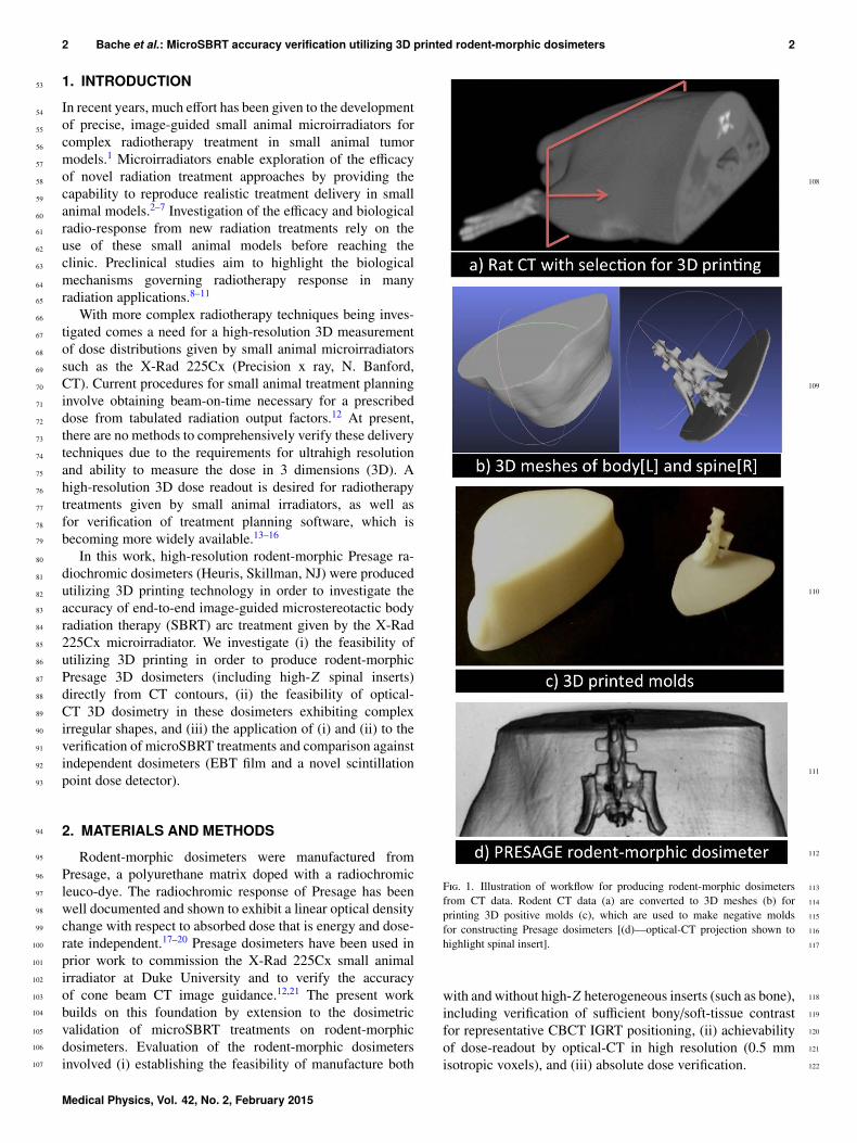
F. 1. Illustration of workflow for producing rodent-morphic dosimetersfrom CT data. Rodent CT data (a) are converted to 3D meshes (b) forprinting 3D positive molds (c), which are used to make negative moldsfor constructing Presage dosimeters [(d)—optical-CT projection shown tohighlight spinal insert].
with and without high-Z heterogeneous inserts (such as bone),including verification of sufficient bony/soft-tissue contrastfor representative CBCT IGRT positioning, (ii) achievabilityof dose-readout by optical-CT in high resolution (0.5 mmisotropic voxels), and (iii) absolute dose verification.
Medical Physics, Vol. 42, No. 2, February 2015
123
124
125
126
127
128
129
130
131
132
133
134
135
136
137
138
139
140
141
142
143
144
145
146
147
148
149
150
151
152
153
154
155
156
157
158
159
160
161
162
163
164
165
166
167
168
169
170
171
172
173
174
175
176
177
178
179
180
181
182
3 Bache et al.: MicroSBRT accuracy verification utilizing 3D printed rodent-morphic dosimeters 3
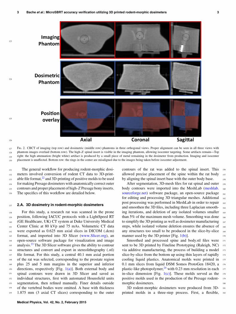
F. 2. CBCT of imaging (top row) and dosimetric (middle row) phantoms in three orthogonal views. Proper alignment can be seen in all three views withphantom images overlaid (bottom row). The high-Z spinal insert is visible in the imaging phantom, allowing isocenter targeting. Some artifacts remain—Topright: the high attenuation (bright white) artifact is produced by a small piece of metal remaining in the dosimeter from production. Imaging and isocenterplacement is unaffected. Bottom row: the rings in the center are misaligned due to the images being taken before isocenter adjustment.
The general workflow for producing rodent-morphic dosi-meters involved conversion of rodent CT data to 3D-print-able file format,22 and 3D-printing of positive molds to be usedfor making Presage dosimeters with anatomically correct outercontours and proper placement of high-Z Presage bony inserts.The specifics of this workflow are detailed below.
2.A. 3D dosimetry in rodent-morphic dosimeters
For this study, a research rat was scanned in the proneposition, following IACUC protocols with a LightSpeed RT(GE Healthcare, UK) CT system at Duke University MedicalCenter Clinic at 80 kVp and 75 mAs. Volumetric CT datawere exported as 0.625 mm axial slices in DICOM (.dcm)format, and imported into 3D Slicer (www.Slicer.org), anopen-source software package for visualization and imageanalysis.23 The 3D Slicer software gives the ability to contourstructures and convert and export in stereolithography (.stl)file format. For this study, a central 40.1 mm axial portionof the rat was selected, corresponding to the prostate regionplus 25 and 5 mm margins in the superior and inferiordirections, respectively [Fig. 1(a)]. Both external body andspinal contours were drawn in 3D Slicer and saved asindividual structures, first with automated Hounsfield unitssegmentation, then refined manually. Finer details outsideof the vertebral bodies were omitted. A base with thickness1.875 mm (3 axial CT slices) corresponding to the outer
contours of the rat was added to the spinal insert. Thisallowed precise placement of the spine within the rat bodyby aligning the spinal insert base with the outer body base.
After segmentation, 3D-mesh files for rat spinal and outerbody contours were imported into the MeshLab (meshlab.sourceforge.net) software package, an open-source packagefor editing and processing 3D triangular meshes. Additionalpost processing was performed in MeshLab in order to repairand smoothen the 3D files, including three Laplacian smooth-ing iterations, and deletion of any isolated volumes smallerthan 5% of the maximum mesh volume. Smoothing was doneto simplify the 3D printing as well as dosimeter manufacturingsteps, while isolated volume deletion ensures the absence ofany structures too small to be produced in the slice-by-slicemanner used by the 3D printer [Fig. 1(b)].
Smoothed and processed spine and body.stl files weresent to be 3D printed by Fineline Prototyping (Raleigh, NC)via additive manufacturing, the process of building a modelslice-by-slice from the bottom up using thin layers of rapidlycooling liquid plastics. Anatomical molds were printed in0.1 mm slices from liquid DSM Somos ProtoGen 18420, aplastic-like photopolymer,24 with 0.23 mm resolution in eachin-slice dimension [Fig. 1(c)]. These molds served as thepositive molds used in the production of the Presage rodent-morphic dosimeters.
3D rodent-morphic dosimeters were produced from 3D-printed molds in a three-step process. First, a flexible,
Medical Physics, Vol. 42, No. 2, February 2015
183
184
185
186
187
188
189
190
191
192
193
194
195
196
197
198
199
200
201
202
203
204
205
206
207
208
209
210
211
212
213
214
215
216
4 Bache et al.: MicroSBRT accuracy verification utilizing 3D printed rodent-morphic dosimeters 4
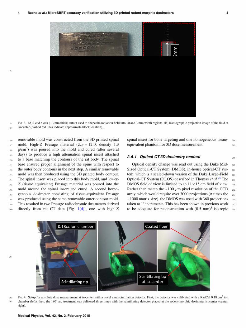
F. 3. (A) Lead block (∼3 mm thick) cutout used to shape the radiation field into 10 and 3 mm width regions. (B) Radiographic projection image of the field atisocenter (dashed red lines indicate approximate block location).
removable mold was constructed from the 3D printed spinalmold. High-Z Presage material (Zeff = 12.0, density 1.3g/cm3) was poured into the mold and cured (after severaldays) to produce a high attenuation spinal insert attachedto a base matching the contours of the rat body. The spinalbase ensured proper alignment of the spine with respect tothe outer body contours in the next step. A similar removablemold was then produced using the 3D printed body contour.The spinal insert was placed into this body mold, and lower-Z (tissue equivalent) Presage material was poured into themold around the spinal insert and cured. A second homo-geneous dosimeter consisting of tissue-equivalent Presagewas produced using the same removable outer contour mold.This resulted in two Presage radiochromic dosimeters deriveddirectly from rat CT data [Fig. 1(d)], one with high-Z
spinal insert for bone targeting and one homogeneous tissue-equivalent phantom for 3D dose measurement.
2.A.1. Optical-CT 3D dosimetry readout
Optical density change was read out using the Duke Mid-Sized Optical-CT System (DMOS), in-house optical-CT sys-tem, which is a scaled-down version of the Duke Large-FieldOptical-CT System (DLOS) described in Thomas et al.25 TheDMOS field of view is limited to an 11×15 cm field of view.Rather than match the ∼100 µm pixel resolution of the CCDarray, which would require over 3000 projections (π times the∼1000 matrix size), the DMOS was used with 360 projectionstaken at 1◦ increments. This has been shown in previous workto be adequate for reconstruction with (0.5 mm)3 isotropic
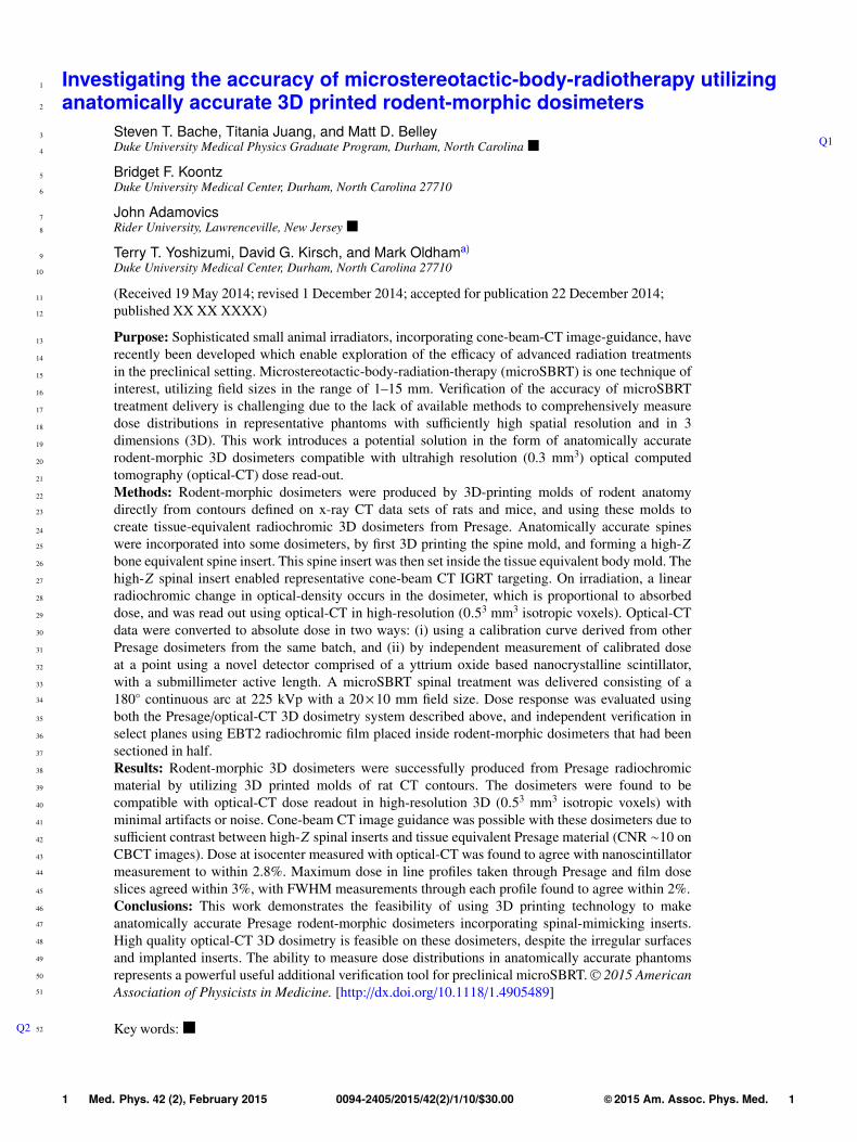
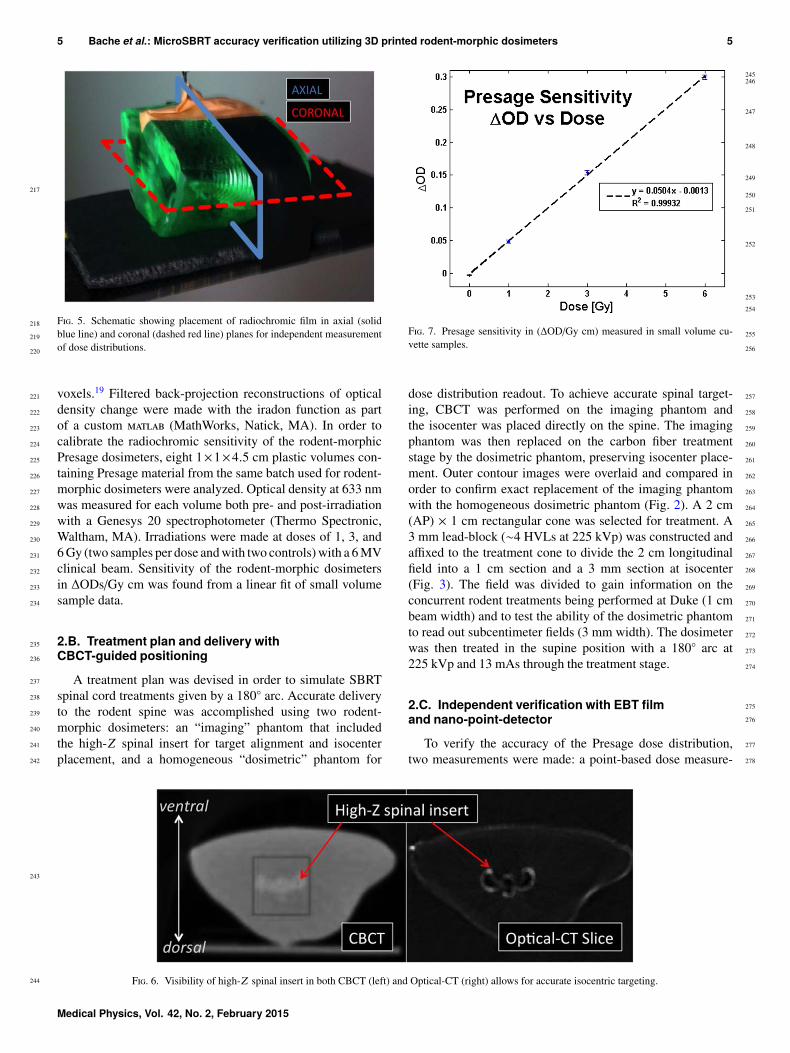
F. 4. Setup for absolute dose measurement at isocenter with a novel nanoscintillation detector. First, the detector was calibrated with a RadCal 0.18 cm3 ionchamber (left), then, the 180◦ arc treatment was delivered three times with the scintillating detector placed at the rodent-morphic dosimeter isocenter (center,right).
Medical Physics, Vol. 42, No. 2, February 2015
217
218
219
220
221
222
223
224
225
226
227
228
229
230
231
232
233
234
235
236
237
238
239
240
241
242
243
244
245246
247
248
249
250
251
252
253
254
255
256
257
258
259
260
261
262
263
264
265
266
267
268
269
270
271
272
273
274
275
276
277
278
5 Bache et al.: MicroSBRT accuracy verification utilizing 3D printed rodent-morphic dosimeters 5
F. 5. Schematic showing placement of radiochromic film in axial (solidblue line) and coronal (dashed red line) planes for independent measurementof dose distributions.
voxels.19 Filtered back-projection reconstructions of opticaldensity change were made with the iradon function as partof a custom (MathWorks, Natick, MA). In order tocalibrate the radiochromic sensitivity of the rodent-morphicPresage dosimeters, eight 1×1×4.5 cm plastic volumes con-taining Presage material from the same batch used for rodent-morphic dosimeters were analyzed. Optical density at 633 nmwas measured for each volume both pre- and post-irradiationwith a Genesys 20 spectrophotometer (Thermo Spectronic,Waltham, MA). Irradiations were made at doses of 1, 3, and6 Gy (two samples per dose and with two controls) with a 6 MVclinical beam. Sensitivity of the rodent-morphic dosimetersin ∆ODs/Gy cm was found from a linear fit of small volumesample data.
2.B. Treatment plan and delivery withCBCT-guided positioning
A treatment plan was devised in order to simulate SBRTspinal cord treatments given by a 180◦ arc. Accurate deliveryto the rodent spine was accomplished using two rodent-morphic dosimeters: an “imaging” phantom that includedthe high-Z spinal insert for target alignment and isocenterplacement, and a homogeneous “dosimetric” phantom for
F. 7. Presage sensitivity in (∆OD/Gy cm) measured in small volume cu-vette samples.
dose distribution readout. To achieve accurate spinal target-ing, CBCT was performed on the imaging phantom andthe isocenter was placed directly on the spine. The imagingphantom was then replaced on the carbon fiber treatmentstage by the dosimetric phantom, preserving isocenter place-ment. Outer contour images were overlaid and compared inorder to confirm exact replacement of the imaging phantomwith the homogeneous dosimetric phantom (Fig. 2). A 2 cm(AP) × 1 cm rectangular cone was selected for treatment. A3 mm lead-block (∼4 HVLs at 225 kVp) was constructed andaffixed to the treatment cone to divide the 2 cm longitudinalfield into a 1 cm section and a 3 mm section at isocenter(Fig. 3). The field was divided to gain information on theconcurrent rodent treatments being performed at Duke (1 cmbeam width) and to test the ability of the dosimetric phantomto read out subcentimeter fields (3 mm width). The dosimeterwas then treated in the supine position with a 180◦ arc at225 kVp and 13 mAs through the treatment stage.
2.C. Independent verification with EBT filmand nano-point-detector
To verify the accuracy of the Presage dose distribution,two measurements were made: a point-based dose measure-
F. 6. Visibility of high-Z spinal insert in both CBCT (left) and Optical-CT (right) allows for accurate isocentric targeting.
Medical Physics, Vol. 42, No. 2, February 2015
279
280
281
282283284285
286
287
288
289
290
291
292
293
294
295
296
297
298299
300
301
302
303
304305306307
308309
310
311
312
313
314
315
316
317
318
319
320
321
322
323
324
325
326
327
328
329
330
331
332
333
334
335
336
6 Bache et al.: MicroSBRT accuracy verification utilizing 3D printed rodent-morphic dosimeters 6
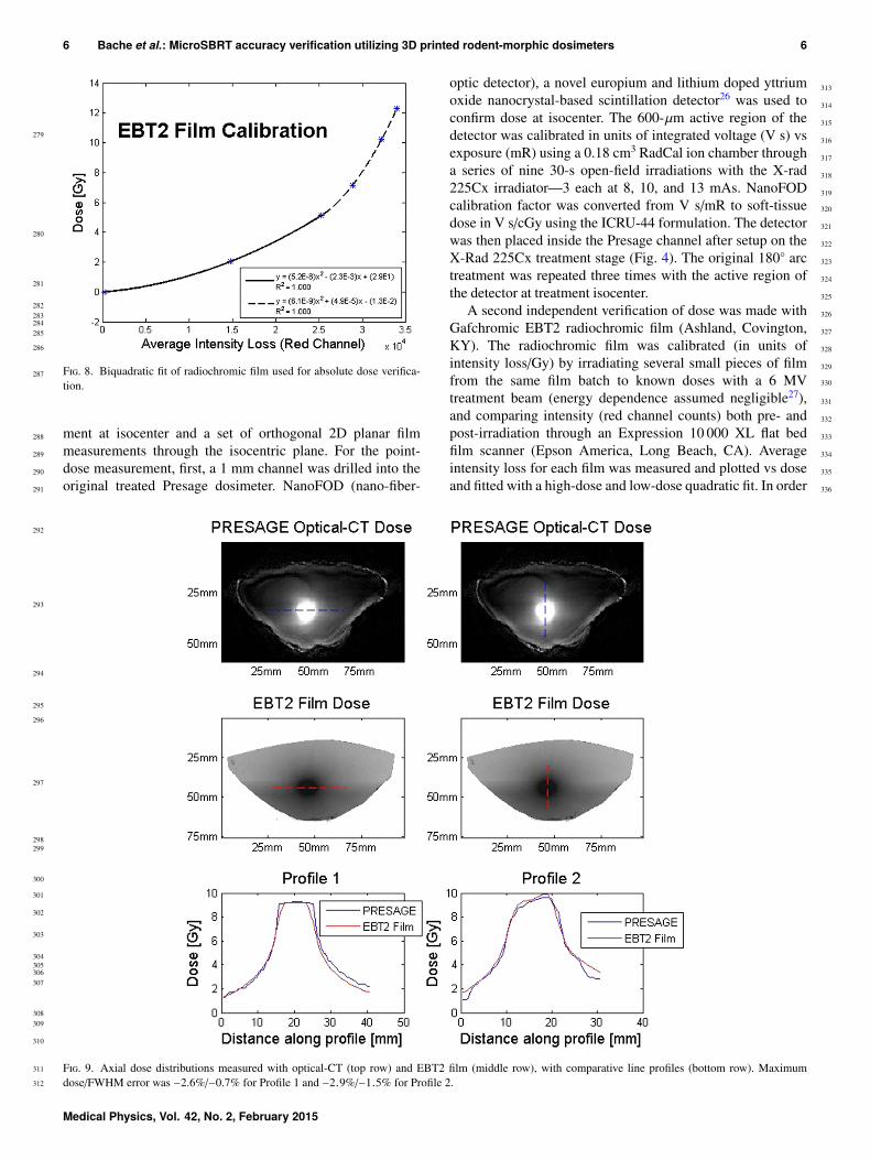
F. 8. Biquadratic fit of radiochromic film used for absolute dose verifica-tion.
ment at isocenter and a set of orthogonal 2D planar filmmeasurements through the isocentric plane. For the point-dose measurement, first, a 1 mm channel was drilled into theoriginal treated Presage dosimeter. NanoFOD (nano-fiber-
optic detector), a novel europium and lithium doped yttriumoxide nanocrystal-based scintillation detector26 was used toconfirm dose at isocenter. The 600-µm active region of thedetector was calibrated in units of integrated voltage (V s) vsexposure (mR) using a 0.18 cm3 RadCal ion chamber througha series of nine 30-s open-field irradiations with the X-rad225Cx irradiator—3 each at 8, 10, and 13 mAs. NanoFODcalibration factor was converted from V s/mR to soft-tissuedose in V s/cGy using the ICRU-44 formulation. The detectorwas then placed inside the Presage channel after setup on theX-Rad 225Cx treatment stage (Fig. 4). The original 180◦ arctreatment was repeated three times with the active region ofthe detector at treatment isocenter.
A second independent verification of dose was made withGafchromic EBT2 radiochromic film (Ashland, Covington,KY). The radiochromic film was calibrated (in units ofintensity loss/Gy) by irradiating several small pieces of filmfrom the same film batch to known doses with a 6 MVtreatment beam (energy dependence assumed negligible27),and comparing intensity (red channel counts) both pre- andpost-irradiation through an Expression 10 000 XL flat bedfilm scanner (Epson America, Long Beach, CA). Averageintensity loss for each film was measured and plotted vs doseand fitted with a high-dose and low-dose quadratic fit. In order
F. 9. Axial dose distributions measured with optical-CT (top row) and EBT2 film (middle row), with comparative line profiles (bottom row). Maximumdose/FWHM error was −2.6%/−0.7% for Profile 1 and −2.9%/−1.5% for Profile 2.
Medical Physics, Vol. 42, No. 2, February 2015
337
338
339
340
341
342
343
344
345
346347
348349350351
352
353354
355
356
357
358
359
360
361
362
363
364
365
366
367
368
369
370
371
372
373
374
375
376
377
378
379
380
381
382
383
384
385
386
387
388
389
390
391
392
7 Bache et al.: MicroSBRT accuracy verification utilizing 3D printed rodent-morphic dosimeters 7
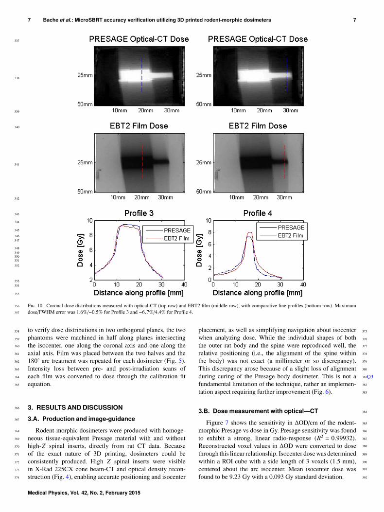
F. 10. Coronal dose distributions measured with optical-CT (top row) and EBT2 film (middle row), with comparative line profiles (bottom row). Maximumdose/FWHM error was 1.6%/−0.5% for Profile 3 and −6.7%/4.4% for Profile 4.
to verify dose distributions in two orthogonal planes, the twophantoms were machined in half along planes intersectingthe isocenter, one along the coronal axis and one along theaxial axis. Film was placed between the two halves and the180◦ arc treatment was repeated for each dosimeter (Fig. 5).Intensity loss between pre- and post-irradiation scans ofeach film was converted to dose through the calibration fitequation.
3. RESULTS AND DISCUSSION3.A. Production and image-guidance
Rodent-morphic dosimeters were produced with homoge-neous tissue-equivalent Presage material with and withouthigh-Z spinal inserts, directly from rat CT data. Becauseof the exact nature of 3D printing, dosimeters could beconsistently produced. High Z spinal inserts were visiblein X-Rad 225CX cone beam-CT and optical density recon-struction (Fig. 4), enabling accurate positioning and isocenter
placement, as well as simplifying navigation about isocenterwhen analyzing dose. While the individual shapes of boththe outer rat body and the spine were reproduced well, therelative positioning (i.e., the alignment of the spine withinthe body) was not exact (a millimeter or so discrepancy).This discrepancy arose because of a slight loss of alignmentduring curing of the Presage body dosimeter. This is not a Q3fundamental limitation of the technique, rather an implemen-tation aspect requiring further improvement (Fig. 6).
3.B. Dose measurement with optical—CT
Figure 7 shows the sensitivity in ∆OD/cm of the rodent-morphic Presage vs dose in Gy. Presage sensitivity was foundto exhibit a strong, linear radio-response (R2 = 0.99932).Reconstructed voxel values in ∆OD were converted to dosethrough this linear relationship. Isocenter dose was determinedwithin a ROI cube with a side length of 3 voxels (1.5 mm),centered about the arc isocenter. Mean isocenter dose wasfound to be 9.23 Gy with a 0.093 Gy standard deviation.
Medical Physics, Vol. 42, No. 2, February 2015
393
394
395
396
397
398
399
400
401
402
403
404
405
406
407
408
409
410
411
412
413
414
415
416
417
418
419
420
421
422
423
424
425
426
427428429
430
431
432
433
434
435
436
437
438
439
440
441
442
443
444
445
446
447
448
449
8 Bache et al.: MicroSBRT accuracy verification utilizing 3D printed rodent-morphic dosimeters 8
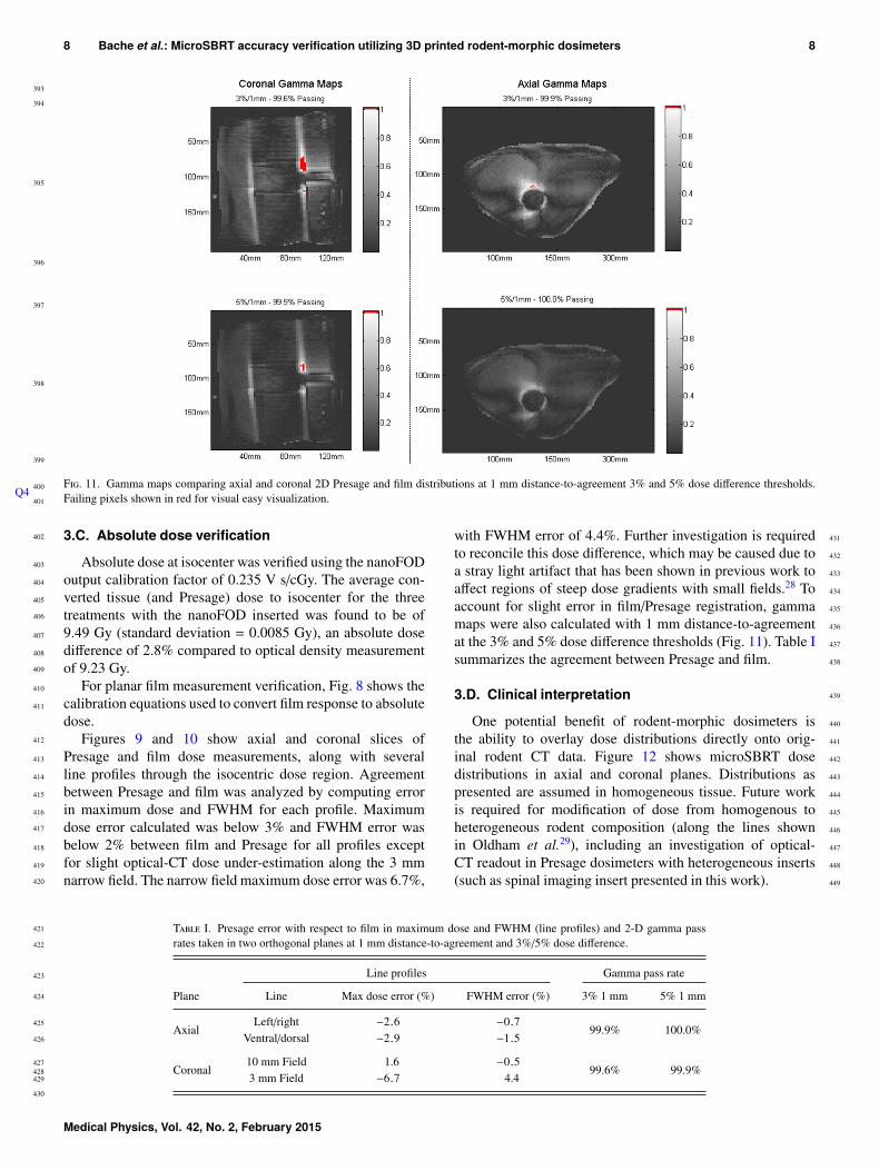
F. 11. Gamma maps comparing axial and coronal 2D Presage and film distributions at 1 mm distance-to-agreement 3% and 5% dose difference thresholds.Failing pixels shown in red for visual easy visualization.
3.C. Absolute dose verification
Absolute dose at isocenter was verified using the nanoFODoutput calibration factor of 0.235 V s/cGy. The average con-verted tissue (and Presage) dose to isocenter for the threetreatments with the nanoFOD inserted was found to be of9.49 Gy (standard deviation = 0.0085 Gy), an absolute dosedifference of 2.8% compared to optical density measurementof 9.23 Gy.
Q4
For planar film measurement verification, Fig. 8 shows thecalibration equations used to convert film response to absolutedose.
Figures 9 and 10 show axial and coronal slices ofPresage and film dose measurements, along with severalline profiles through the isocentric dose region. Agreementbetween Presage and film was analyzed by computing errorin maximum dose and FWHM for each profile. Maximumdose error calculated was below 3% and FWHM error wasbelow 2% between film and Presage for all profiles exceptfor slight optical-CT dose under-estimation along the 3 mmnarrow field. The narrow field maximum dose error was 6.7%,
with FWHM error of 4.4%. Further investigation is requiredto reconcile this dose difference, which may be caused due toa stray light artifact that has been shown in previous work toaffect regions of steep dose gradients with small fields.28 Toaccount for slight error in film/Presage registration, gammamaps were also calculated with 1 mm distance-to-agreementat the 3% and 5% dose difference thresholds (Fig. 11). Table Isummarizes the agreement between Presage and film.
3.D. Clinical interpretation
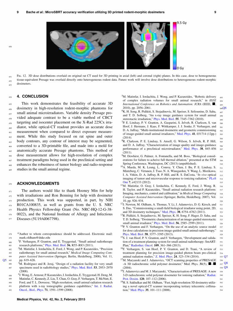
One potential benefit of rodent-morphic dosimeters isthe ability to overlay dose distributions directly onto orig-inal rodent CT data. Figure 12 shows microSBRT dosedistributions in axial and coronal planes. Distributions aspresented are assumed in homogeneous tissue. Future workis required for modification of dose from homogenous toheterogeneous rodent composition (along the lines shownin Oldham et al.29), including an investigation of optical-CT readout in Presage dosimeters with heterogeneous inserts(such as spinal imaging insert presented in this work).
T I. Presage error with respect to film in maximum dose and FWHM (line profiles) and 2-D gamma passrates taken in two orthogonal planes at 1 mm distance-to-agreement and 3%/5% dose difference.
Line profiles Gamma pass rate
Plane Line Max dose error (%) FWHM error (%) 3% 1 mm 5% 1 mm
AxialLeft/right −2.6 −0.7
99.9% 100.0%Ventral/dorsal −2.9 −1.5
Coronal10 mm Field 1.6 −0.5
99.6% 99.9%3 mm Field −6.7 4.4
Medical Physics, Vol. 42, No. 2, February 2015
450
451
452
453
454
455
456
457
458
459
460
461
462
463
464
465
466
467
468
469
470
471
472
473
474
475
476
477
478
479
480
481
482
483
484
485
486
487
488
489
490
491
492
493
494
495
496
497
498
499
500
501
502
503
504
505
506
507
508
509
510
511
512
513
514
515
516
517
518
519
520
521
522
523
524
525
526
527
528
529
530
531
532
533
534
535
536
537
538
539
540
541
542
543
544
9 Bache et al.: MicroSBRT accuracy verification utilizing 3D printed rodent-morphic dosimeters 9
F. 12. 3D dose distributions overlaid on original rat CT used for 3D printing in axial (left) and coronal (right) planes. In this case, dose to homogeneoustissue-equivalent Presage was overlaid directly onto heterogeneous rodent data. Future work will involve dose distributions to heterogeneous rodent-morphicdosimeters.
4. CONCLUSION
This work demonstrates the feasibility of accurate 3Ddosimetry in high-resolution rodent-morphic phantoms forsmall animal microirradiators. Variable density Presage pro-vided adequate contrast to be a viable method of CBCTtargeting and isocenter placement on the X-Rad 225Cx irra-diator, while optical-CT readout provides an accurate dosemeasurement when compared to direct exposure measure-ment. While this study focused on rat spine and outerbody contours, any contour of interest may be segmented,converted to a 3D-printable file, and made into a mold foranatomically accurate Presage phantoms. This method ofdose measurement allows for high-resolution of complextreatment paradigms being used in the preclinical setting andenhances the robustness of tumor biology and radio-responsestudies in the small animal regime.
ACKNOWLEDGMENTS
The authors would like to thank Hooney Min for helpwith irradiations and Ron Benning for help with dosimeterproduction. This work was supported, in part, by NIHR01CA100835, as well as grants from the U. S. NRCHealth Physics Fellowship Grant (No. NRC-HQ-12-G-38-0022), and the National Institute of Allergy and InfectiousDiseases (5U19AI067798).
a)Author to whom correspondence should be addressed. Electronic mail:[email protected]
1F. Verhaegen, P. Granton, and E. Tryggestad, “Small animal radiotherapyresearch platforms,” Phys. Med. Biol. 56, R55–R83 (2011).
2M. Matinfar, I. Iordachita, E. Ford, J. Wong, and P. Kazanzides, “Precisionradiotherapy for small animal research,” Medical Image Computing Com-puter Assisted Intervention (Springer, Berlin, Heidelberg, 2008), Vol. 11,pp. 619–626.Q5
3M. Rodriguez and R. Jeraj, “Design of a radiation facility for very smallspecimens used in radiobiology studies,” Phys. Med. Biol. 53, 2953–2970(2008).
4J. Wong, E. Armour, P. Kazanzides, I. Iordachita, E. Tryggestad, H. Deng, M.Matinfar, C. Kennedy, Z. Liu, T. Chan, O. Gray, F. Verhaegen, T. McNutt, E.Ford, and T. L. Deweese, “High-resolution, small animal radiation researchplatform with x-ray tomographic guidance capabilities,” Int. J. Radiat.Oncol., Biol., Phys. 71, 1591–1599 (2008).
5M. Matinfar, I. Iordachita, J. Wong, and P. Kazanzides, “Robotic deliveryof complex radiation volumes for small animal research,” in IEEEInternational Conference on Robotics and Automation: ICRA (IEEE, ■,2010), pp. 2056–2061. Q6
6K. H. Song, R. Pidikiti, S. Stojadinovic, M. Speiser, S. Seliounine, D. Saha,and T. D. Solberg, “An x-ray image guidance system for small animalstereotactic irradiation,” Phys. Med. Biol. 55, 7345–7362 (2010).
7P. E. Lindsay, P. V. Granton, A. Gasparini, S. Jelveh, R. Clarkson, S. vanHoof, J. Hermans, J. Kaas, F. Wittkamper, J. J. Sonke, F. Verhaegen, andD. A. Jaffray, “Multi-institutional dosimetric and geometric commissioningof image-guided small animal irradiators,” Med. Phys. 41, 031714 (12pp.)(2014).
8R. Clarkson, P. E. Lindsay, S. Ansell, G. Wilson, S. Jelveh, R. P. Hill,and D. A. Jaffray, “Characterization of image quality and image-guidanceperformance of a preclinical microirradiator,” Med. Phys. 38, 845–856(2011).
9M. Dewhirst, G. Palmer, A. Fontanella, and M. Boss, “Biological consid-erations for failure to acheive full thermal ablation,” presented at the STMSpring Conference, Washington, DC (2013) (unpublished).
10A. Maeda, M. K. Leung, L. Conroy, Y. Chen, J. Bu, P. E. Lindsay, S.Mintzberg, C. Virtanen, J. Tsao, N. A. Winegarden, Y. Wang, L. Morikawa,I. A. Vitkin, D. A. Jaffray, R. P. Hill, and R. S. DaCosta, “In vivo opticalimaging of tumor and microvascular response to ionizing radiation,” PLoSOne 7, e42133 (2012).
11M. Matinfar, O. Gray, I. Iordachita, C. Kennedy, E. Ford, J. Wong, R.H. Taylor, and P. Kazanzides, “Small animal radiation research platform:Imaging, mechanics, control and calibration,” in Medical Image ComputingComputer Assisted Intervention (Springer, Berlin, Heidelberg, 2007), Vol.10, pp. 926–934.
12J. Newton, M. Oldham, A. Thomas, Y. Li, J. Adamovics, D. G. Kirsch, andS. Das, “Commissioning a small-field biological irradiator using point, 2D,and 3D dosimetry techniques,” Med. Phys. 38, 6754–6762 (2011).
13R. Pidikiti, S. Stojadinovic, M. Speiser, K. H. Song, F. Hager, D. Saha, andT. D. Solberg, “Dosimetric characterization of an image-guided stereotacticsmall animal irradiator,” Phys. Med. Biol. 56, 2585–2599 (2011).
14P. V. Granton and F. Verhaegen, “On the use of an analytic source modelfor dose calculations in precision image-guided small animal radiotherapy,”Phys. Med. Biol. 58, 3377–3395 (2013).
15S. J. van Hoof, P. V. Granton, and F. Verhaegen, “Development and valida-tion of a treatment planning system for small animal radiotherapy: SmART-Plan,” Radiother. Oncol. 109, 361–366 (2013).
16F. Verhaegen, S. van Hoof, P. V. Granton, and D. Trani, “A review oftreatment planning for precision image-guided photon beam pre-clinicalanimal radiation studies,” Z. Med. Phys. 24, 323–334 (2014). Q7
17M. Maryanski and J. Adamovics, “OCT scanning properties of PRESAGE-A 3D radiochromic solid polymer dosimeter,” Med. Phys. 31(5), ■–■(2004).
Q8Q9
18J. Adamovics and M. J. Maryanski, “Characterisation of PRESAGE: A new3-D radiochromic solid polymer dosemeter for ionising radiation,” Radiat.Prot. Dosim. 120, 107–112 (2006).
19H. S. Sakhalkar and M. Oldham, “Fast, high-resolution 3D dosimetry utiliz-ing a novel optical-CT scanner incorporating tertiary telecentric collima-tion,” Med. Phys. 35, 101–111 (2008).
Medical Physics, Vol. 42, No. 2, February 2015
545
546
547
548
549
550
551
552
553
554
555
556
557
558
559
560
561
562
563
564
565
566
567
568
569
570
571
572
573
574
575
576
577
578
579
580
10 Bache et al.: MicroSBRT accuracy verification utilizing 3D printed rodent-morphic dosimeters 10
20R. Hill, T. Gorjiara, Z. Kuncic, J. Adamovics, S. Bosi, J. H. Kim, and C.Baldock, “Investigation of radiological properties and water equivalency ofPRESAGE dosimeters,” Med. Phys. 38, 2265–2274 (2011).
Q10
21L. J. Rankine, J. Newton, S. T. Bache, S. Das, J. Adamovics, D. G. Kirsch,and M. Oldham, “Investigating end-to-end accuracy of image guided radi-ation treatment delivery using a micro-irradiator,” Phys. Med. Biol. 58,7791–7801 (2013).
22E. Doney, L. A. Krumdick, J. M. Diener, C. A. Wathen, S. E. Chapman, B.Stamile, J. E. Scott, M. J. Ravosa, T. Van Avermaete, and W. M. Leevy, “3Dprinting of preclinical x-ray computed tomographic data sets,” J. VisualizedExp. 73, e50250 (2013).
23A. Fedorov, R. Beichel, J. Kalpathy-Cramer, J. Finet, J. C. Fillion-Robin, S.Pujol, C. Bauer, D. Jennings, F. Fennessy, M. Sonka, J. Buatti, S. R. Aylward,J. V. Miller, S. Pieper, and R. Kikinis, “3D slicer as an image computingplatform for the quantitative imaging network,” Magn. Reson. Imaging 30,1323–1341 (2012).
24See www.dsmsomos.com for “Somos Protogen 18420 material data SafetySheet” (accessed 2013).
25A. Thomas, J. Newton, J. Adamovics, and M. Oldham, “Commissioningand benchmarking a 3D dosimetry system for clinical use,” Med. Phys. 38,4846–4857 (2011).
26I. Stanton, M. Belley, G. Nguyen, A. Rodrigues, Y. Li, D. Kirsch, T.Yoshizumi, and M. Therien, “Europium- and lithium-doped yttrium oxidenanocrystals that provide a linear emissive response with x-ray radiationexposure,” Nanoscale 6(10), 5284–5288 (2014).
27B. Arjomandy, R. Tailor, A. Anand, N. Sahoo, M. Gillin, K. Prado, and M.Vicic, “Energy dependence and dose response of Gafchromic EBT2 filmover a wide range of photon, electron, and proton beam energies,” Med.Phys. 37(5), 1942–1947 (2010).
28A. Thomas, M. Pierquet, K. Jordan, and M. Oldham, “A method to cor-rect for spectral artifacts in optical-CT dosimetry,” Phys. Med. Biol. 56,3403–3416 (2011).
29M. Oldham, A. Thomas, J. O’Daniel, T. Juang, G. Ibbot, J. Adamovics, andJ. Kirkpatrick, “A quality assurance method that utilizes 3D dosimetry andfacilitates clinical interpretation,” Int. J. Radiat. Oncol., Biol., Phys. 84(2),540–546 (2012).
Medical Physics, Vol. 42, No. 2, February 2015