
VHF Omnidirectional Range (VOR) Experimental Positioning ...

PII S0360-3016(02)02895-X
PHYSICS CONTRIBUTION
LIMITED-DATA IMAGE REGISTRATION FOR RADIOTHERAPYPOSITIONING AND VERIFICATION
KENNETH J. RUCHALA, PH.D.,* GUSTAVO H. OLIVERA, PH.D.,*†AND JEFFREY M. KAPATOES, PH.D.*
*TomoTherapy Inc., Middleton, WI;†Department of Medical Physics, University of Wisconsin-Madison, Madison, WI
Purpose: One benefit to having on-line CT imaging integrated into a radiotherapy system is that images can becollected with the patient in the treatment position. These images can then be automatically registered toplanning images for improved positioning and verification. However, many such on-line imaging systems have alimited field of view (LFOV) that could potentially impair registration. Thus, the viability of automaticregistration was investigated in the context of collecting on-line LFOV and also limited-slice CT images forradiotherapy.Methods and Materials: Mutual information and two new voxel-based registration algorithms were tested toalign LFOV and limited-slice prostate and breast images given known displacements. Success rates were talliedfor different field-of-view sizes, slice distributions, and initial displacements.Results: Most of the automatic registration algorithms tested were useful for solving these LFOV and limited-slice problems. Registration of LFOV images was generally successful, especially for fields of view of at least halfthe patient’s size. For limited-slice images, success was more closely correlated to the slice spacing than to thenumber of slices used, with sparse slice spacing being preferable.Conclusions: Mutual information and other automatic registration algorithms have been identified as usefulmethods for registering LFOV and limited-slice radiotherapy images with planning CT images. © 2002 ElsevierScience Inc.
Image fusion, Image registration, Adaptive radiotherapy, On-line CT, IMRT.
INTRODUCTION
The topic of automatic image registration has been exten-sively investigated for both single-modality and multimo-dality images. One particularly promising set of registrationalgorithms uses voxel-based methods. These algorithms an-alyze a match between two images using individual voxelvalues, as opposed to other techniques that might alignfiducial points or match surfaces or gradients, etc. (1). Someof the most prevalent voxel-based methods are mutual in-formation (MI)(2–4) and normalized mutual information (5,6). These have been previously demonstrated to be gener-ally fast and robust and also capable of registering multi-modality images. Other proposed voxel-based registrationmethods include joint entropy, the correlation ratio (7, 8),and the use of joint intensity distributions (9).
One field that may benefit from automatic image regis-tration is image-guided radiotherapy (IGRT). IGRT is anadvanced form of intensity-modulated radiotherapy (IMRT)that combines the precision delivery capabilities of IMRTwith improved patient anatomic information. The benefit is
that with three-dimensional images such as CT, one candiscern a patient’s position and anatomy more clearly thanwith external fiducials or radiographs. It is particularlybeneficial to have these systems on-line, because this en-ables acquisition of images with the patient in the treatmentposition. If necessary, this information can be used to mod-ify the patient’s position or adapt the IMRT treatmentaccordingly (10–12).
Registration can assist with the comparison of the on-lineimages to the planning images. An on-line image set, ac-quired before daily treatment, can be registered to the plan-ning image set to verify patient positioning or indicate apreferable repositioning of the patient. Likewise, other ver-ification techniques, such as delivery verification and dosereconstruction, are most appropriately applied to on-lineimages (13). In this context, registration helps to identifyhow a reconstructed dose in the on-line images correspondsto the intended dose in the planning images.
However, one common problem with many current on-line imaging systems for IGRT is that they can have alimited field of view (LFOV). For current tomotherapy
Please address all correspondence to: Kenneth J. Ruchala, To-moTherapy Inc., 2228 Evergreen Rd., Middleton, WI 53562. Tel:(608) 824-0995, ext. 106; Fax: (608) 824-0996; E-mail:[email protected]
Portions of this work were presented at ASTRO 2001, SanFrancisco, CA.
Acknowledgments—The authors are very thankful to Dr. Di Yanfor providing the multi-day patient CT images and accompanyingmanual registration data collected at William Beaumont Hospital.
Received Sep 4, 2001, and in revised form Apr 12, 2002.Accepted for publication Apr 18, 2002.
Int. J. Radiation Oncology Biol. Phys., Vol. 54, No. 2, pp. 592–605, 2002Copyright © 2002 Elsevier Science Inc.Printed in the USA. All rights reserved
0360-3016/02/$–see front matter
592
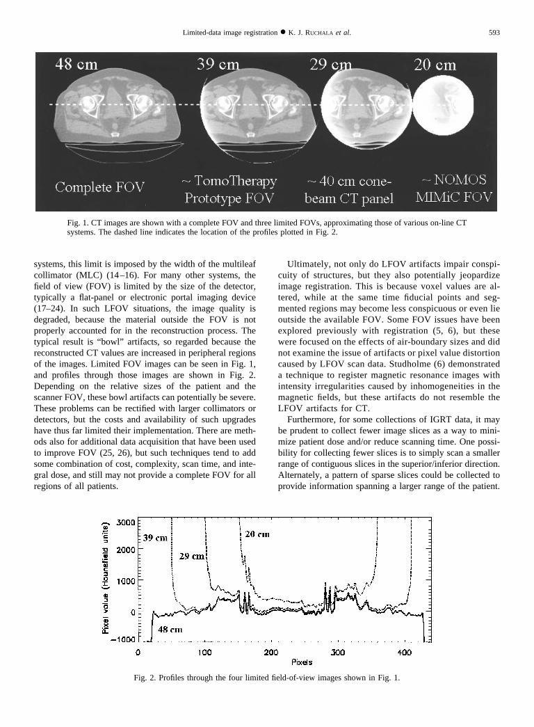
systems, this limit is imposed by the width of the multileafcollimator (MLC) (14–16). For many other systems, thefield of view (FOV) is limited by the size of the detector,typically a flat-panel or electronic portal imaging device(17–24). In such LFOV situations, the image quality isdegraded, because the material outside the FOV is notproperly accounted for in the reconstruction process. Thetypical result is “bowl” artifacts, so regarded because thereconstructed CT values are increased in peripheral regionsof the images. Limited FOV images can be seen in Fig. 1,and profiles through those images are shown in Fig. 2.Depending on the relative sizes of the patient and thescanner FOV, these bowl artifacts can potentially be severe.These problems can be rectified with larger collimators ordetectors, but the costs and availability of such upgradeshave thus far limited their implementation. There are meth-ods also for additional data acquisition that have been usedto improve FOV (25, 26), but such techniques tend to addsome combination of cost, complexity, scan time, and inte-gral dose, and still may not provide a complete FOV for allregions of all patients.
Ultimately, not only do LFOV artifacts impair conspi-cuity of structures, but they also potentially jeopardizeimage registration. This is because voxel values are al-tered, while at the same time fiducial points and seg-mented regions may become less conspicuous or even lieoutside the available FOV. Some FOV issues have beenexplored previously with registration (5, 6), but thesewere focused on the effects of air-boundary sizes and didnot examine the issue of artifacts or pixel value distortioncaused by LFOV scan data. Studholme (6) demonstrateda technique to register magnetic resonance images withintensity irregularities caused by inhomogeneities in themagnetic fields, but these artifacts do not resemble theLFOV artifacts for CT.
Furthermore, for some collections of IGRT data, it maybe prudent to collect fewer image slices as a way to mini-mize patient dose and/or reduce scanning time. One possi-bility for collecting fewer slices is to simply scan a smallerrange of contiguous slices in the superior/inferior direction.Alternately, a pattern of sparse slices could be collected toprovide information spanning a larger range of the patient.
Fig. 1. CT images are shown with a complete FOV and three limited FOVs, approximating those of various on-line CTsystems. The dashed line indicates the location of the profiles plotted in Fig. 2.
Fig. 2. Profiles through the four limited field-of-view images shown in Fig. 1.
593Limited-data image registration ● K. J. RUCHALA et al.

In these cases, too, the reduced amount of data may impairautomatic image registration.
Thus, there are several goals of this work:
1. Evaluate the ability of various voxel-based algorithms toregister incomplete field-of-view on-line images withcomplete field-of-view planning images;
2. Test registration performance for on-line images that areboth LFOV and limited slice;
3. Using same-patient, different-day image sets, comparethe registration results for different voxel-based algo-rithms to independently determined manual registrationresults.
AlgorithmsPreliminary tests for this study included a variety of
algorithms, such as the well-known mutual information,normalized mutual information, and joint entropy algo-rithms. Additionally, two newly developed algorithms weretested: cropped mutual information (CMI) and extractedfeature fusion (EFF). These initial tests indicated that in thecontext of this study, both normalized mutual informationand joint entropy behaved similarly to mutual information,so they were not pursued further.
Mutual informationAs mentioned above, the mutual information algorithm
is voxel based in that it quantifies how well two imagesare aligned using corresponding voxel values for a testedoverlap position. A simple example of a voxel-basedmethod is taking a least-squares difference between over-lapping voxel values from each image. However, manyvoxel-based methods create what is known as either ajoint histogram or a bivariate histogram, from which anumber of different statistical measures can be calculatedto quantify the fit of the transformed images. This biva-riate histogram is the basis of mutual information andalso underlies the new and modified algorithms studiedhere.
In particular, the two axes of the bivariate histogram arethe range of values in each of the two images, and the valuesin the joint histogram are tallies of how often each value inthe floating image overlaps each value in the referenceimage. That is, one begins with a voxel in floating imageand uses the current estimate of translations and rotationsbetween the two images to determine the correspondinglocation of that voxel in the reference image. A value isinterpolated for that location in the reference image. Thebivariate histogram is then updated by incrementing thetally at coordinates (floating image value, reference imagevalue).
Mathematically, this can be described as applying a six-parameter rigid-body transformation, T�, to one of the im-ages and tallying a bivariate histogram, h� (f, r), as afunction of the floating image, f, and the reference image, r.The probability distributions needed to calculate mutual
information can be obtained from this bivariate histogram(4):
pFR,�� f, r� �h�� f, r�
�f,r
h�� f, r�
pF,�� f � � �r
pFR,�� f, r�
pR,��r� � �f
pFR,�� f, r�
These three probability distributions represent the two-di-mensional normalized bivariate histogram and the one-di-mensional normalized distributions of values in the over-lapping portions of each image, respectively. Each of theseprobability distributions is subscripted with the transforma-tion parameter �, to underscore that these histograms arebased on the transformation-dependent set of overlappingpoints in the floating and reference images. Given theseprobability distributions, mutual information can be evalu-ated with the following equation:
I��� � �f,r
pFR,�� f, r� log2
pFR,�� f, r�
pF,�� f � pR,��r�. (1)
Given this ability to quantify the alignment for any trans-formation �, it is possible to use an optimization strategy todetermine the transformation �* that maximizes the mutualinformation.
Cropped mutual informationOne straightforward modification to the mutual informa-
tion algorithm was developed for this study to potentiallymake it more robust in the presence of LFOV artifacts:Instead of using all voxels from the floating image to createthe bivariate histogram, only voxels within a certain radiusof the center of each slice were used. In other words, pointstoo close to the image boundaries were discarded, becausethese were more likely to have their CT values compro-mised by artifacts. This is referred to as cropped mutualinformation, or CMI. Thus, CMI potentially avoids usingmany of the voxels whose values have been most egre-giously affected.
Extracted feature fusionWhen creating the bivariate histogram for mutual infor-
mation, one typically either uses all of the overlappingpoints in the two images or reduces this number via regulardownsampling to reduce computation time. It was postu-lated that greater reductions in computation time would bepossible if the number of image points could be further, yetselectively, reduced. For example, this could mean applyinga mutual information–style calculation only to extractedfeatures, such as thresholded bony points, in a given floatingimage.
594 I. J. Radiation Oncology ● Biology ● Physics Volume 54, Number 2, 2002

In terms of radiotherapy patient positioning, such a tech-nique could potentially be as good, if not better, than mutualinformation. This is because in cases where the patient’sanatomy has not changed, the bony registration resultshould be the same as the full-body registration result. Yetin the context of anatomy changes, aligning underlyingbony structures for radiotherapy positioning may be moreappropriate than matching more amorphous structures, suchas the outer contour (27). Additionally, bony alignmentprovides a useful reference frame for additional measures oforgan deformation (28).
However, attempting to use the mutual information algo-rithm in this way was generally unreliable. Likewise, relatedstatistical measures, such as normalized mutual informationand joint entropy, frequently produced incorrect results. Inall of these cases, it was witnessed that for small changes inthe applied transformation, the value of registration metricmight change disproportionately, and these fluctuationswere closely related to large positional dependencies of themarginal probability functions, pF,� and pR,�. That is, whenpF,� and pR,� are based on complete or regularly down-sampled images, they are generally more stable for smallchanges in the transformation than when they are based onsets of extracted points.
Thus, another variation of mutual information was devel-oped; in this variation, the fluctuations can be mitigated byreplacing the histogram-based marginal probabilities pF,�
and pR,� in Eq. 1 with the a priori marginal probabilities.That is, instead of determining pF,� and pR,� for each trans-formation tested based on the overlapping points, the apriori probabilities pF and pR are calculated based on all ofthe points in each image, regardless of the overlap. Tofurther damp variations in the histograms, the bivariatehistogram is normalized to a constant, c (e.g., the totalnumber of image points), instead of to the sum of thebivariate histogram (the number of overlapping points). Thedifference is that some voxels from the floating image mapto outside of the reference image. Because this differencevaries with the transformation applied, it could destabilizethe convergence of the optimization. Ultimately, this changein normalization effectively penalizes potential alignmentsin which the extracted features of the floating image map tooutside the reference image. This is a very reasonable as-sumption, because the LFOV region is expected to be asubset of the complete FOV image.
Thus this algorithm, referred to as extracted feature fu-sion, or EFF, can be expressed mathematically as the fol-lowing equation:
EFF��� � �f,r
p�FR,�� f, r� log2
p�FR,�� f, r�
pF� f � pR�r�
where
p�FR,�� f, r� �h�� f, r�
c.
Although the discussion of extracted features may cause thisalgorithm to seem less automatic than mutual information,the feature extraction step by no means requires manualsegmentation or other manual intervention. Instead, thefeature extraction step used in this study was simply anautomatic selection of points with densities above a giventhreshold, although more complex selection criteria couldbe applied. Practically, just as the distortion of image valuesfrom LFOV artifacts might impair fusion, this distortioncould also be a detriment to the selection of voxels for theEFF algorithm, so it was not intuitively obvious whetherEFF would be more or less robust than MI with regard toLFOV artifacts.
METHODS AND MATERIALS
Limited-data image volumesThe data sets used for this study were clinical CT images.
This is because the goal of this work is to analyze theviability of clinical setup using limited-data images; in suchcircumstances, one is typically comparing an on-line CTimage to a planning CT image. Two sites in particular,breast and prostate, were extensively tested for their regis-tration viability under various limited-data situations.
To test the registration results for different fields of viewand different numbers of slices, the appropriate limited-dataimage sets were needed. For the limited-slice case, thisentailed no more than selecting automatically a pattern ofslices. These patterns are characterized by two parameters:number of batches and slices per batch. A batch is simply agroup of slices, and when multiple batches were used, theywere regularly spaced. Each batch had the same number ofslices.
The limited-slice configurations tested are shown sche-matically in Fig. 3. There were typically 61 slices in eachprostate CT, and the control case was to keep all slices, asrepresented by the top row of Fig. 3. However, each limited-slice test case used only four to eight slices total; the totalnumber of slices is the number of batches multiplied by theslices per batch. As illustrated in Fig. 3, these limited-slice
Fig. 3. A schematic of the slice selection used for each limited-slice case. Each horizontal row represents the 61 CT slice locationsin one of the complete prostate data sets. Dots indicate that theslice is not used, and vertical lines indicate that a slice is used.
595Limited-data image registration ● K. J. RUCHALA et al.

configurations ranged from a single batch of four slices toeight batches of one slice each.
To create image volumes representing the fields of viewof various on-line imaging systems, the original imageswere first forward projected into sinograms (29, 30). Animage slice and its corresponding sinogram are shown inFigs. 4a and 4b. Specifically, this sinogram is a two-dimen-sional matrix in which the horizontal axis represents detec-tor position, and the vertical axis represents gantry angle.Each value in the sinogram represents the ray-integral ofattenuation through the patient for a given gantry angle anddetector position. The sinogram shown in Fig. 4b has acomplete FOV, but if the FOV were limited, attenuationinformation would not be available for the full lateral extentof the patient. Such an LFOV sinogram is shown in Fig. 4c,representing a CT scanner with FOV of 29 cm, meaning thatdata are acquired only for the central 29 cm of the patient ateach angle. Reconstruction is the mathematical process ofconverting a sinogram back into a CT image; the LFOVimage that results from the LFOV sinogram (Fig. 4c) isshown in Fig. 4d. These LFOV images maintained the samepixel size as the original images, yet had smaller imagedimensions, ranging from 212 � 212 with the smallest FOV
to 512 � 512 for complete FOV. Dashed lines were addedbetween Figs. 4a and 4b and between Figs. 4c and 4d toillustrate the correlation between the image FOV and thesinogram FOV.
Experimental designIn this study, a series of image registrations is attempted,
and in each attempt, images have a different random startingposition relative to one another. After this series of attempts,the success rate of the registration method can be analyzed.Repeating the series of attempts using the same set ofstarting positions but different registration methods allowsdifferent registration techniques to be compared. This pro-cess is similar to that of other registration studies mentionedabove (5, 31, 32).
In fact, two sets of random starting positions were createdto represent sets of smaller and larger offsets, with 50starting positions in each set. Each starting position wasdefined by six parameters: translations in the x, y, and zdirections, and rotations about those three axes, called pitch,yaw, and roll. The starting points in the smaller-offset setwere randomly chosen using zero-mean normal distribu-tions that had standard deviations of 10 mm in each trans-lation direction and 5° in each rotation direction. For thelarger-offset starting points, the corresponding standard de-viations were 20 mm and 10 degrees. In practice, many ofthese starting points in both sets represent atypically largepatient positioning errors during radiotherapy.
When scoring the results of these tests, a registrationresult was considered successful if the final translation errorwas less than half a pixel width in each direction, and if thecombined root-mean-square of the three rotational errorswas less than half a degree. These translational acceptancetolerances are intuitive in the context of using nearest-neighbor interpolation to tabulate the reference image val-ues for each bivariate histogram. Although it is believedpossible to achieve subvoxel accuracy with voxel-basedregistration techniques (1, 4, 33), such was not tested,because it would have exceeded the ability to reposition aradiotherapy patient. The justification for the Boolean suc-cess criterion, as witnessed previously (5, 32), is that virtu-ally all tested cases either succeeded for these tolerances orfailed unambiguously. Near-misses were very uncommon,so modifying these success tolerances or using more com-plex evaluation criteria would have a negligible effect onthe results.
A final set of tests was designed to investigate registrationin the presence of normal anatomic changes over the courseof a radiotherapy treatment. The image volumes were ac-quired at William Beaumont Hospital and included from 15to 17 CT data sets for each of three patients, taken onalternating days of each patient’s treatment. The daily ana-tomic changes preclude an unambiguously correct answerfor the image registration. Instead, the manual alignmentsdetermined by a physician were included with these datasets and were taken as the standard. The physician’s align-
Fig. 4. The creation of LFOV image volumes, proceeding from (a)the complete FOV image volume to (b) the complete FOV sino-gram, or CT data, for the complete FOV image, to (c) the subsetof (b) that would be collected for a 29-cm LFOV system, to (d) theCT image that would be generated on the LFOV system. Thedashed lines show the correspondence between image FOV andthe sinogram FOV.
596 I. J. Radiation Oncology ● Biology ● Physics Volume 54, Number 2, 2002

ments were based primarily on the matching of bony anat-omy (28).
For each of the three patients, one image set was selectedas the reference set, and all of the other sets were regardedas on-line images. There happened to be a total of 50 imagesets, and therefore three reference images and 47 on-lineimages to be registered. Thus, for each registration algo-rithm, limited-slice case, and FOV, 47 different registra-tions were attempted using the CT patient images fromdifferent days. In this case, the “correct answers” were notknown random displacements, but the results from physi-cian-defined manual alignment.
Because for these cases there was imprecision in both theregistration calculation and the standard results, the successtolerances needed to be expanded. The new criteria werechosen in accordance with clinical repositioning needs andhad values of 2 mm in each translation direction and acombined root-mean-square difference of 1.0° for the threerotations.
Experimental implementationOne conceptual note is that from an algorithmic stand-
point, the goal is to determine the success of registrationgiven two images (one LFOV, one full FOV) and differentsets of rotations and translations between them. This couldbe examined either by using a single planning image andregistering it to LFOV images “collected” at each of thedifferent starting positions, or it could be done by trans-forming the planning image by the different starting posi-tions relative to the different “collected” LFOV images. Forthis study, the latter approach was selected, because itsubstantially reduced the computational burden in thatLFOV data sets did not need to be created for each of thedifferent fields of view at each of the 100 starting positions.
Computation time was also improved by downsamplingeach LFOV or limited-slice image by a factor of 4 in eachof the two in-plane dimensions. Resulting transverse sliceshad in-plane dimensions ranging from 53 � 53 for thesmallest FOV to 128 � 128 for complete FOV. However,the planning images were not downsampled; instead, eachpoint of the LFOV or limited-slice CT was mapped to alocation in the planning image. There was no noticeablechange in accuracy or precision when using this downsam-pling paradigm. This was confirmed by performing regis-trations for 300 initial positions, first with downsampling,then without, and comparing the histograms of results foreach set.
Additional preliminary testing was used to select thedifferent outer radii for the cropped mutual informationalgorithm, namely 20 and 40 pixels, corresponding to 1.9and 3.6 cm. The feature extraction for the EFF algorithmwas done by simple thresholding, and two main cases wereconsidered: thresholding tissue and bony points by selectingdensities greater than 0.3 g/cm3 and thresholding primarilybony points by selecting densities above 1.1 g/cm3. TheEFF algorithm also ignored potential extracted-feature vox-els within 20 pixels of the outer radius, akin to CMI, to
avoid some of the most distorted CT values. For this study,optimization was performed using the well-known methodsof Brent and Powell, described in Press et al. (34).
RESULTS
LFOV resultsA sample result of registration with the EFF algorithm is
shown in Fig. 5. The top row shows two transverse slices, acoronal slice, and a sagittal slice of the initial alignmentbetween the planning image and the LFOV floating image.The bottom row shows the alignment after applying the EFFalgorithm.
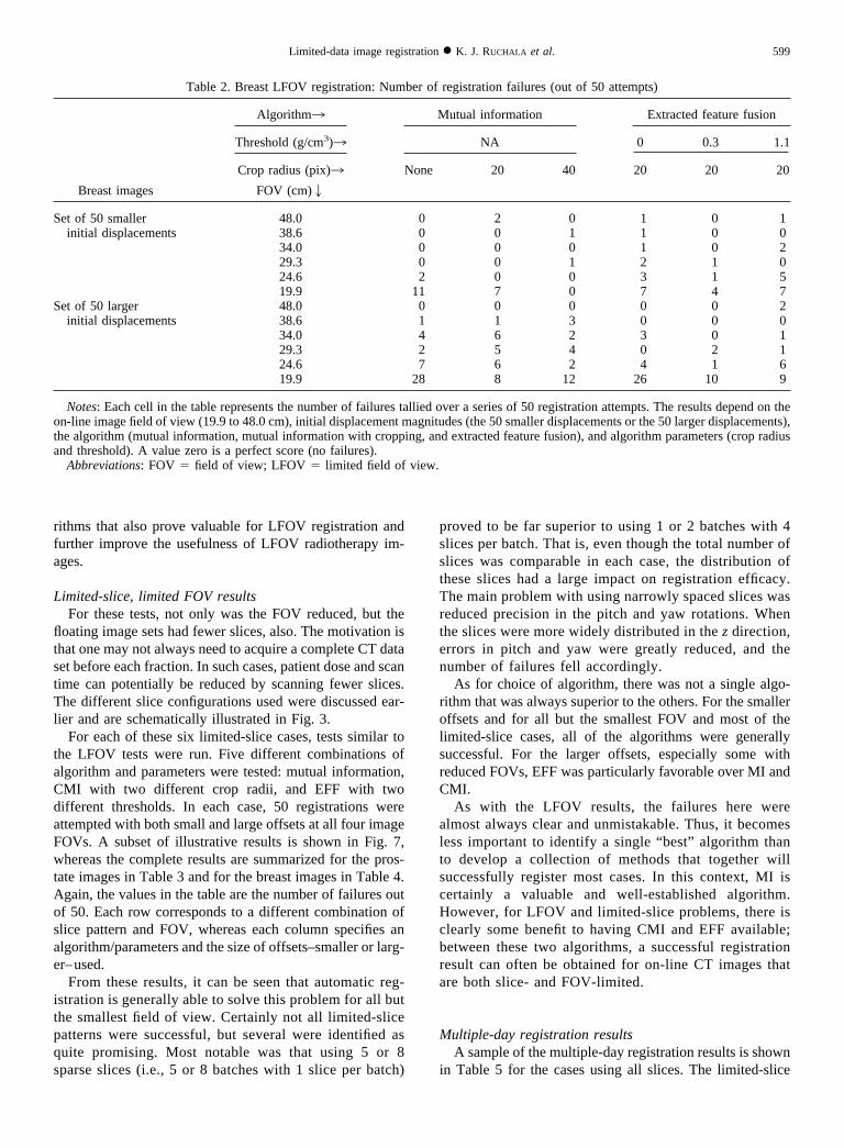
The complete LFOV registration results are shown inTables 1 and 2 for the prostate and breast images, respec-tively. Specifically, each table tallies the number of failuresof each algorithm as a function of the different algorithm-parameter combinations vs. the FOV. A perfect score iszero, meaning no failures result from that combination ofalgorithm and parameters at that FOV. A score of 50 indi-cates that every registration attempt failed. Each table in-cludes a section for the set of 50 smaller offsets and asection for the set of 50 larger offsets. In addition, anillustrative subset of the quantitative results for the LFOVtests is shown in Fig. 6.
For the smaller initial displacements, and for all but thetwo smallest FOV sizes, all of the algorithms had two orfewer failures, which is a success rate of more than 96%.Further reductions in the FOV increased the number offailures. Unmodified MI failed the most often; the EFFalgorithm was somewhat better, and CMI with a 40-pixelboundary removal was particularly successful.
For the larger-displacement set, similar patterns ap-peared, although the number of failures was greater, andmore failures appeared at larger FOV sizes. Again, theunmodified MI algorithm was particularly prone to failure,especially for the prostate images. The EFF algorithm didfairly well for both the breast and prostate for all but thesmallest FOV. CMI had the fewest failures for the smallestFOV, but was somewhat worse than the EFF algorithm forother image sizes.
As might be expected, success is greatest when the FOVis nearly complete, because in those cases, there are moreimage data with less severe artifacts. Yet, even for theimage FOVs down to about half the patient’s size, somemethods remained effective. For many radiotherapy sys-tems with on-line CT, this criterion is satisfied for mostpatient sites.
Certainly the effectiveness of different algorithms de-pends on image content, initial six-parameter displace-ments, and FOV size, as well as on algorithm parameterssuch as the outer-ring crop distance and feature extractionthreshold. For the images, algorithms, and parameterstested, there was not a single optimal algorithm and param-eter set. However, as mentioned above, the number of “ localfailures” was negligible, meaning that virtually all of theregistration results were either successful or grossly inac-
597Limited-data image registration ● K. J. RUCHALA et al.

curate, making them easy to identify. For the successfulalignments, all algorithms had similar precision and accu-racy. Thus in clinical conditions, it would be practical to runmultiple algorithms or parameters and dismiss any obvi-ously flawed results. Also, because the size of the initialdisplacement does affect the success rate, even a coarsemanual registration before the automatic registration couldsignificantly improve the results.
The feasibility of LFOV registration enhances the utilityof images from radiotherapy systems with on-line CT im-aging. Although there was not a definitive best algorithmunder all conditions, the EFF algorithm did succeed in anumber of cases when others failed, making it a usefuloption to have available. Additionally, EFF typically ranseveral times faster than MI and CMI, because it used fewerimage points. However, there certainly may be other algo-
Table 1. Prostate LFOV registration: Number of registration failures (out of 50 attempts)
Prostate images
Algorithm3 Mutual information Extracted feature fusion
Threshold (g/cm3)3 NA 0 0.3 1.1
Crop radius (pix)3 None 20 40 20 20 20
FOV (cm) 2
Set of 50 smaller 48.0 0 0 0 0 0 0initial displacements 38.6 0 0 1 0 0 0
34.0 0 0 0 0 1 029.3 0 0 1 0 1 224.6 7 0 0 2 0 019.9 41 6 0 16 16 17
Set of 50 largerinitial displacements
48.0 1 0 1 0 0 038.6 0 1 0 0 0 034.0 10 0 4 2 0 229.3 13 8 8 0 0 024.6 37 23 12 4 3 119.9 50 37 18 45 45 45
Notes: Each cell in the table represents the number of failures tallied over a series of 50 registration attempts. The results depend on theon-line image field of view (19.9 to 48.0 cm), initial displacement magnitudes (the 50 smaller displacements or the 50 larger displacements),the algorithm (mutual information, mutual information with cropping, and extracted feature fusion), and algorithm parameters (crop radiusand threshold). A value zero is a perfect score (no failures).
Abbreviations: FOV � field of view; LFOV � limited field of view.
Fig. 5. The alignments of a planning image with an LFOV floating image both (top) before and (bottom) afterregistration with the EFF algorithm. The translations were 4.2 cm, 4.2 cm, and 2.6 cm in x, y, and z, and rotations were8.9°, 14.7°, and 32.5° in pitch, yaw, and roll.
598 I. J. Radiation Oncology ● Biology ● Physics Volume 54, Number 2, 2002
rithms that also prove valuable for LFOV registration andfurther improve the usefulness of LFOV radiotherapy im-ages.
Limited-slice, limited FOV resultsFor these tests, not only was the FOV reduced, but the
floating image sets had fewer slices, also. The motivation isthat one may not always need to acquire a complete CT dataset before each fraction. In such cases, patient dose and scantime can potentially be reduced by scanning fewer slices.The different slice configurations used were discussed ear-lier and are schematically illustrated in Fig. 3.
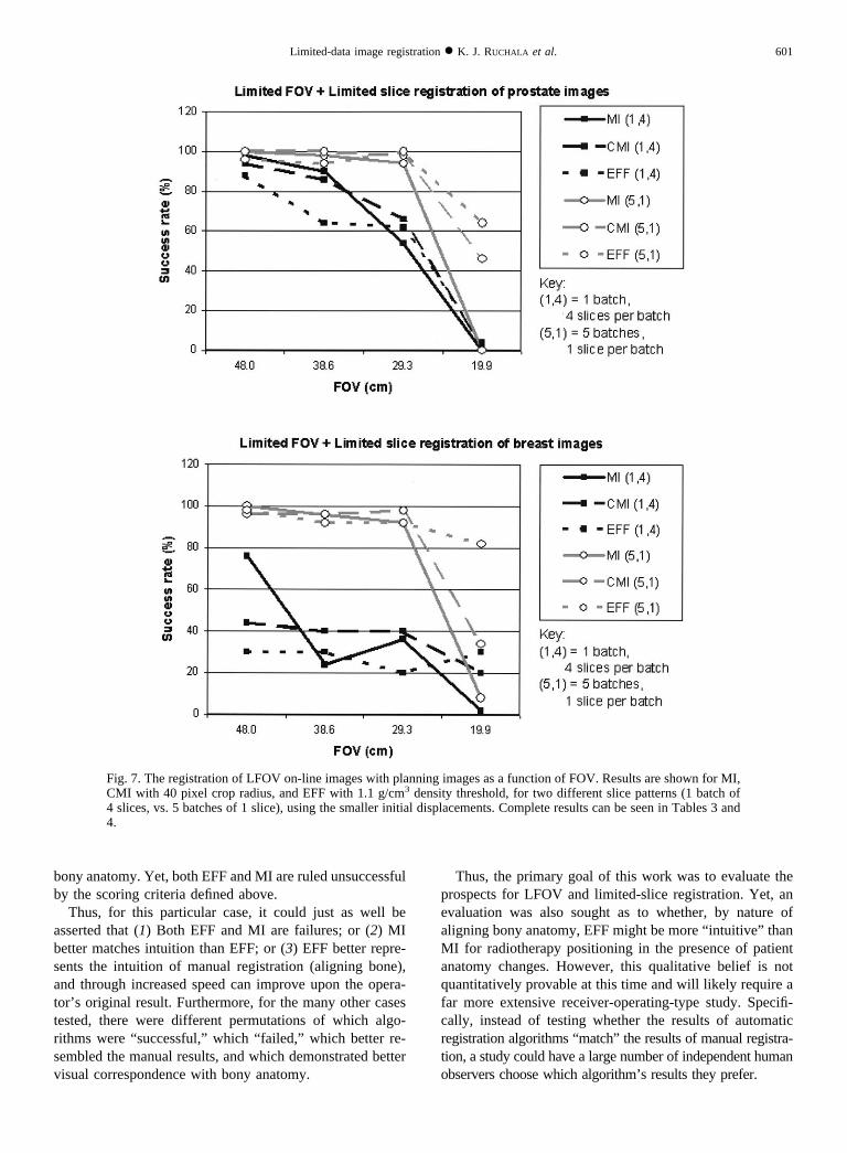
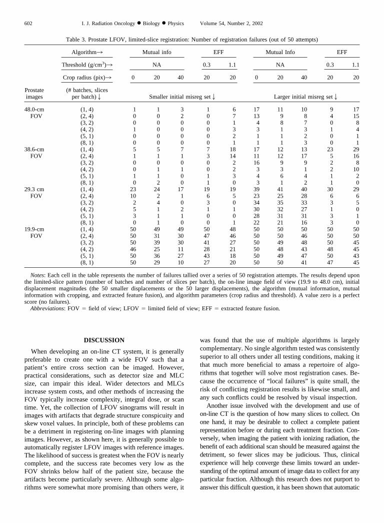
For each of these six limited-slice cases, tests similar tothe LFOV tests were run. Five different combinations ofalgorithm and parameters were tested: mutual information,CMI with two different crop radii, and EFF with twodifferent thresholds. In each case, 50 registrations wereattempted with both small and large offsets at all four imageFOVs. A subset of illustrative results is shown in Fig. 7,whereas the complete results are summarized for the pros-tate images in Table 3 and for the breast images in Table 4.Again, the values in the table are the number of failures outof 50. Each row corresponds to a different combination ofslice pattern and FOV, whereas each column specifies analgorithm/parameters and the size of offsets–smaller or larg-er–used.
From these results, it can be seen that automatic reg-istration is generally able to solve this problem for all butthe smallest field of view. Certainly not all limited-slicepatterns were successful, but several were identified asquite promising. Most notable was that using 5 or 8sparse slices (i.e., 5 or 8 batches with 1 slice per batch)
proved to be far superior to using 1 or 2 batches with 4slices per batch. That is, even though the total number ofslices was comparable in each case, the distribution ofthese slices had a large impact on registration efficacy.The main problem with using narrowly spaced slices wasreduced precision in the pitch and yaw rotations. Whenthe slices were more widely distributed in the z direction,errors in pitch and yaw were greatly reduced, and thenumber of failures fell accordingly.
As for choice of algorithm, there was not a single algo-rithm that was always superior to the others. For the smalleroffsets and for all but the smallest FOV and most of thelimited-slice cases, all of the algorithms were generallysuccessful. For the larger offsets, especially some withreduced FOVs, EFF was particularly favorable over MI andCMI.
As with the LFOV results, the failures here werealmost always clear and unmistakable. Thus, it becomesless important to identify a single “best” algorithm thanto develop a collection of methods that together willsuccessfully register most cases. In this context, MI iscertainly a valuable and well-established algorithm.However, for LFOV and limited-slice problems, there isclearly some benefit to having CMI and EFF available;between these two algorithms, a successful registrationresult can often be obtained for on-line CT images thatare both slice- and FOV-limited.
Multiple-day registration resultsA sample of the multiple-day registration results is shown
in Table 5 for the cases using all slices. The limited-slice
Table 2. Breast LFOV registration: Number of registration failures (out of 50 attempts)
Breast images
Algorithm3 Mutual information Extracted feature fusion
Threshold (g/cm3)3 NA 0 0.3 1.1
Crop radius (pix)3 None 20 40 20 20 20
FOV (cm)2
Set of 50 smallerinitial displacements
48.0 0 2 0 1 0 138.6 0 0 1 1 0 034.0 0 0 0 1 0 229.3 0 0 1 2 1 024.6 2 0 0 3 1 519.9 11 7 0 7 4 7
Set of 50 largerinitial displacements
48.0 0 0 0 0 0 238.6 1 1 3 0 0 034.0 4 6 2 3 0 129.3 2 5 4 0 2 124.6 7 6 2 4 1 619.9 28 8 12 26 10 9
Notes: Each cell in the table represents the number of failures tallied over a series of 50 registration attempts. The results depend on theon-line image field of view (19.9 to 48.0 cm), initial displacement magnitudes (the 50 smaller displacements or the 50 larger displacements),the algorithm (mutual information, mutual information with cropping, and extracted feature fusion), and algorithm parameters (crop radiusand threshold). A value zero is a perfect score (no failures).
Abbreviations: FOV � field of view; LFOV � limited field of view.
599Limited-data image registration ● K. J. RUCHALA et al.

results are not included, because they were very similar tothe cases shown in Table 5.
These results show very similar results for all algorithmvariations, although mutual information did slightly worsethan the others. This could be crudely construed as a dem-onstration that EFF and CMI better mimic a human observ-er’s positioning. Yet, more telling is that each of the algo-rithms failed for about half of its cases. For this reason, it isinteresting to examine why there were so many failures.
One fundamental problem was that the assumption thatmanual registration could be used as a standard was lesspromising than anticipated. Obviously, because the imagesbeing registered represent a patient on different days, there
is no definitively correct answer, only operator preference.Moreover, although operator preference indicates an accept-able alignment, it is very reasonable to assume that otherpossibilities, not tried for practical reasons, might have beenpreferable.
An example of these complexities is shown in Fig. 8. Thetop three images (a) are slices of the reference and floatingimages, aligned manually at William Beaumont Hospital. Inthe middle are the alignments obtained using EFF. Thebottom row shows the same images for MI registration. Oneimportant point about this case is that visually, the MI resultbetter matches the manual result. However, EFF does abetter job than both manual registration and MI of aligning
Fig. 6. The registration of LFOV on-line images with planning images as a function of FOV. Results are shown for MI,CMI with 40 pixel crop radius, and EFF with 1.1 g/cm3 density threshold, for both small and large initial displacements.Complete results can be seen in Tables 1 and 2.
600 I. J. Radiation Oncology ● Biology ● Physics Volume 54, Number 2, 2002
bony anatomy. Yet, both EFF and MI are ruled unsuccessfulby the scoring criteria defined above.
Thus, for this particular case, it could just as well beasserted that (1) Both EFF and MI are failures; or (2) MIbetter matches intuition than EFF; or (3) EFF better repre-sents the intuition of manual registration (aligning bone),and through increased speed can improve upon the opera-tor’s original result. Furthermore, for the many other casestested, there were different permutations of which algo-rithms were “successful,” which “ failed,” which better re-sembled the manual results, and which demonstrated bettervisual correspondence with bony anatomy.
Thus, the primary goal of this work was to evaluate theprospects for LFOV and limited-slice registration. Yet, anevaluation was also sought as to whether, by nature ofaligning bony anatomy, EFF might be more “ intuitive” thanMI for radiotherapy positioning in the presence of patientanatomy changes. However, this qualitative belief is notquantitatively provable at this time and will likely require afar more extensive receiver-operating-type study. Specifi-cally, instead of testing whether the results of automaticregistration algorithms “match” the results of manual registra-tion, a study could have a large number of independent humanobservers choose which algorithm’s results they prefer.
Fig. 7. The registration of LFOV on-line images with planning images as a function of FOV. Results are shown for MI,CMI with 40 pixel crop radius, and EFF with 1.1 g/cm3 density threshold, for two different slice patterns (1 batch of4 slices, vs. 5 batches of 1 slice), using the smaller initial displacements. Complete results can be seen in Tables 3 and4.
601Limited-data image registration ● K. J. RUCHALA et al.
DISCUSSION
When developing an on-line CT system, it is generallypreferable to create one with a wide FOV such that apatient’s entire cross section can be imaged. However,practical considerations, such as detector size and MLCsize, can impair this ideal. Wider detectors and MLCsincrease system costs, and other methods of increasing theFOV typically increase complexity, integral dose, or scantime. Yet, the collection of LFOV sinograms will result inimages with artifacts that degrade structure conspicuity andskew voxel values. In principle, both of these problems canbe a detriment in registering on-line images with planningimages. However, as shown here, it is generally possible toautomatically register LFOV images with reference images.The likelihood of success is greatest when the FOV is nearlycomplete, and the success rate becomes very low as theFOV shrinks below half of the patient size, because theartifacts become particularly severe. Although some algo-rithms were somewhat more promising than others were, it
was found that the use of multiple algorithms is largelycomplementary. No single algorithm tested was consistentlysuperior to all others under all testing conditions, making itthat much more beneficial to amass a repertoire of algo-rithms that together will solve most registration cases. Be-cause the occurrence of “ local failures” is quite small, therisk of conflicting registration results is likewise small, andany such conflicts could be resolved by visual inspection.
Another issue involved with the development and use ofon-line CT is the question of how many slices to collect. Onone hand, it may be desirable to collect a complete patientrepresentation before or during each treatment fraction. Con-versely, when imaging the patient with ionizing radiation, thebenefit of each additional scan should be measured against thedetriment, so fewer slices may be judicious. Thus, clinicalexperience will help converge these limits toward an under-standing of the optimal amount of image data to collect for anyparticular fraction. Although this research does not purport toanswer this difficult question, it has been shown that automatic
Table 3. Prostate LFOV, limited-slice registration: Number of registration failures (out of 50 attempts)
Prostateimages
Algorithm3 Mutual info EFF Mutual Info EFF
Threshold (g/cm3)3 NA 0.3 1.1 NA 0.3 1.1
Crop radius (pix)3 0 20 40 20 20 0 20 40 20 20
(# batches, slicesper batch)2 Smaller initial misreg set2 Larger initial misreg set2
48.0-cmFOV
(1, 4) 1 1 3 1 6 17 11 10 9 17(2, 4) 0 0 2 0 7 13 9 8 4 15(3, 2) 0 0 0 0 1 4 8 7 0 8(4, 2) 1 0 0 0 3 3 1 3 1 4(5, 1) 0 0 0 0 2 1 1 2 0 1(8, 1) 0 0 0 0 1 1 1 3 0 1
38.6-cmFOV
(1, 4) 5 5 7 7 18 17 12 13 23 29(2, 4) 1 1 1 3 14 11 12 17 5 16(3, 2) 0 0 0 0 2 16 9 9 2 8(4, 2) 0 1 1 0 2 3 3 1 2 10(5, 1) 1 1 0 1 3 4 6 4 1 2(8, 1) 0 2 0 1 0 3 1 2 1 0
29.3 cmFOV
(1, 4) 23 24 17 19 19 39 41 40 30 29(2, 4) 10 2 1 6 5 23 25 28 6 6(3, 2) 2 4 0 3 0 34 35 33 3 5(4, 2) 5 1 2 1 1 30 32 27 1 0(5, 1) 3 1 1 0 0 28 31 31 3 1(8, 1) 0 1 0 0 1 22 21 16 3 0
19.9-cmFOV
(1, 4) 50 49 49 50 48 50 50 50 50 50(2, 4) 50 31 30 47 46 50 50 46 50 50(3, 2) 50 39 30 41 27 50 49 48 50 45(4, 2) 46 25 11 28 21 50 48 43 48 45(5, 1) 50 36 27 43 18 50 49 47 50 43(8, 1) 50 29 10 27 20 50 50 41 47 45
Notes: Each cell in the table represents the number of failures tallied over a series of 50 registration attempts. The results depend uponthe limited-slice pattern (number of batches and number of slices per batch), the on-line image field of view (19.9 to 48.0 cm), initialdisplacement magnitudes (the 50 smaller displacements or the 50 larger displacements), the algorithm (mutual information, mutualinformation with cropping, and extracted feature fusion), and algorithm parameters (crop radius and threshold). A value zero is a perfectscore (no failures).
Abbreviations: FOV � field of view; LFOV � limited field of view; EFF � extracted feature fusion.
602 I. J. Radiation Oncology ● Biology ● Physics Volume 54, Number 2, 2002

registration is feasible even for a reduced number of slices.Moreover, for a given number of slices to be collected, sparsespacing of these slices better enabled automatic registration
than narrow spacing. Thus, while a primary goal of on-line CTis to view anatomic changes, the ability to contextually framethis information is abetted by automatic registration.
Table 4. Breast LFOV, limited-slice registration: Number of registration failures (out of 50 attempts)
Breastimages
Algorithm3 Mutual info EFF Mutual info EFF
Threshold (g/cm3)3 NA 0.3 1.1 NA 0.3 1.1
Crop radius (pix)3 0 20 40 20 20 0 20 40 20 20
(# batches, slicesper batch)2 Smaller initial misreg set2 Larger initial misreg set2
48.0-cmFOV
(1, 4) 12 31 28 23 35 22 26 22 33 41(2, 4) 4 12 15 16 14 8 13 15 17 25(3, 2) 1 0 1 4 5 0 0 1 3 11(4, 2) 2 5 1 8 6 2 5 10 2 10(5, 1) 0 0 2 1 1 0 1 8 1 10(8, 1) 1 1 1 2 0 1 2 2 1 6
38.6-cmFOV
(1, 4) 38 31 30 29 35 38 33 30 40 44(2, 4) 12 10 9 7 6 21 17 19 5 15(3, 2) 1 1 1 2 8 11 8 9 1 7(4, 2) 4 2 1 0 4 8 3 8 2 2(5, 1) 2 0 2 2 4 7 5 5 1 5(8, 1) 0 0 0 3 1 5 2 3 1 0
29.3-cmFOV
(1, 4) 32 31 30 35 40 34 39 39 42 47(2, 4) 14 9 10 9 5 20 24 21 13 12(3, 2) 3 0 2 3 0 14 15 12 4 2(4, 2) 0 2 2 1 2 5 15 17 6 2(5, 1) 4 1 1 0 4 9 15 19 2 4(8, 1) 1 0 0 3 1 3 8 8 2 3
19.9-cmFOV
(1, 4) 49 42 40 43 35 49 49 49 50 49(2, 4) 34 27 33 37 21 44 37 46 48 47(3, 2) 31 18 11 32 9 49 36 42 47 33(4, 2) 32 17 14 23 7 47 34 36 33 13(5, 1) 46 37 33 43 9 50 45 50 49 24(8, 1) 32 14 14 21 3 50 36 32 42 10
Notes: Each cell in the table represents the number of failures tallied over a series of 50 registration attempts. The results depend on thelimited-slice pattern (number of batches and number of slices per batch), the on-line image field of view (19.9 to 48.0 cm), initialdisplacement magnitudes (the 50 smaller displacements or the 50 larger displacements), the algorithm (mutual information, mutualinformation with cropping, and extracted feature fusion), and algorithm parameters (crop radius and threshold). A value zero is a perfectscore (no failures).
Abbreviations: FOV � field of view; LFOV � limited field of view; EFF � extracted feature fusion.
Table 5. Prostate LFOV registration for different-day images: Number of registration failures (out of 47 attempts)
Prostateimages
FOV (cm) 2
Mutual information Extracted feature fusion
CMI crop radius (pixels)2 EFF threshold (g/cm3)2
None 20 40 0.3 1.1
48.0 30 28 25 28 2038.6 30 25 26 26 2329.3 31 24 24 24 2419.9 36 30 31 32 33
Notes: Each cell in the table represents the number of failures tallied over a series of 47 registration attempts. These attempts are basedupon patient CT volumes from different days, with the “correct” registration result for each of the 47 attempts defined by a physician’smanual registration. This table shows how the failure rate depends on the on-line image field of view (19.9 to 48.0 cm), the algorithm(mutual information, mutual information with cropping, and extracted feature fusion), and algorithm parameters (crop radius and threshold).A value of zero is a perfect score (no failures). Use of different limited-slice patterns had little effect on the results.
Abbreviations: FOV � field of view; LFOV � limited field of view; CMI � mutual information with cropping; EFF � extracted featurefusion.
603Limited-data image registration ● K. J. RUCHALA et al.

Finally, of the algorithms tested for these registrationproblems, EFF stood out when registering different-dayimages, because visual inspection seemed to indicate thatEFF reflected intuition better than MI did for bony align-ment of prostate images. However, this point eluded quan-titative analysis. Many “ failed” registration runs from eachof the algorithms seemed to provide matches between thereference and floating images that were comparable or evensuperior to the manual results used as the standard. Thus, forthe difficult question of evaluating registration results amidchanges in patient anatomy, further studies are warranted.
CONCLUSION
Several algorithms have been identified that are generallysuccessful at automatically registering limited field-of-viewand limited-slice images. This mitigates a potential down-side of many on-line imaging systems for radiotherapy that
often have limited fields of view. These algorithms—mutualinformation, cropped mutual information, and extracted fea-ture fusion—were typically able to register artifact-riddenon-line images with fields of view down to about one-half apatient’s size. Moreover, substantially reducing the numberof slices in an image set was not so much a problem as washaving the slices too narrowly spaced in the z direction.
The extracted feature fusion algorithm has been testedand shown to be generally effective for registering planningimages and on-line images, and is particularly beneficial inthe case of LFOV and limited-slice alignment. It can alsoprovide substantial speed improvements by nature of usingfewer image points. Even so, MI, CMI, and EFF are allgenerally successful at aligning LFOV and limited-sliceon-line images with complete FOV planning images. Theability to perform this registration ultimately enhances thebenefit of acquiring on-line CT images with a radiotherapysystem.
Fig. 8. A sample comparison of reference and planning CT image sets aligned via (a) manual fusion, (b) EFF, and (c)MI. By the success criteria defined, both EFF and MI are “ failures.” However, in this case, the MI result more closelyresembles the manual result, whereas EFF does a better job than the other two at aligning bony anatomy.
604 I. J. Radiation Oncology ● Biology ● Physics Volume 54, Number 2, 2002
REFERENCES
1. Hill D, Batchelor P, Holden M, et al. Medical image registra-tion. Phys Med Biol 2001;46:R1–R45.
2. Wells WMI, Viola P, Atsumi H, et al. Multi-modal volumeregistration by maximization of mutual information. MedicalImage Analysis 1996;1:35–51.
3. Viola P, Wells WMI. Alignment by maximization of mutualinformation. Int J Computer Vision 1997;24:137–154.
4. Maes F, Collignon A, Vandermeulen D, et al. Multimodalityimage registration by maximization of mutual information.IEEE Trans Med Imaging 1997;16:187–198.
5. Studholme C, Hill D, Hawkes D. An overlap invariant entropymeasure of 3D medical image alignment. Pattern Recognition1999;32:71–86.
6. Studholme C. Measures of 3D medical image alignment.Division of Radiological Sciences. London: University ofLondon; 1997.
7. Roche A, Malandain G, Pennec X, et al. The correlation ratioas a new similarity measure for multimodal image registration.Medical image computing and computer-assisted interven-tion—MICCAI’98. Berlin: Springer-Verlag; 1998. p. 1115–1124.
8. Roche A, Malandain G, Ayache N, et al. Towards a bettercomprehension of similarity measures used in medical imageregistration. Medical image computing and computer-assistedintervention—MICCAI’99. Berlin: Springer-Verlag; 1999. p.555–566.
9. Leventon M, Grimson WE. Multi-modal volume registrationusing joint intensity distributions. Medical image computingand computer-assisted intervention—MICCAI’98. Berlin:Springer-Verlag; 1998. p. 1057–1066.
10. Yan D, Vicini F, Wong J, et al. Adaptive radiation therapy.Phys Med Biol 1997;42:123–132.
11. Olivera G, Fitchard E, Reckwerdt P, et al. Delivery modifi-cation as an alternative to patient repositioning in tomo-therapy. In: Schlegel W, Bortfeld T, editors. XIII InternationalConference on Computers in Radiotherapy. Heidelberg, Ger-many: Springer-Verlag; 2000. p. 297–299.
12. Hua C, Lovelock M, Mageras G, et al. Online prostate posi-tion correction using 5 CT slices for prostate cancer patientsundergoing image-guided external beam radiotherapy (ab-stract). Med Phys 2001;28:1258.
13. Kapatoes J, Olivera G, Ruchala K, et al. A feasible method forclinical delivery verification and dose reconstruction in tomo-therapy. Med Phys 2001;28:528–542.
14. Ruchala K, Olivera G, Kapatoes J, et al. Megavoltage CTreconstruction during tomotherapy treatments. Phys Med Biol2000;45:3545–3562.
15. Ruchala K, Olivera G, Kapatoes J, et al. Megavoltage CTimaging as a by-product of multi-leaf collimator leakage. PhysMed Biol 2000;45:N61–N70.
16. Ruchala K, Olivera G, Schloesser E, et al. Megavoltage CT ona tomotherapy system. Phys Med Biol 1999;44:2597–2621.
17. Guan H, Zhu Y. Feasibility of megavoltage portal CT using anelectronic portal imaging device (EPID) and a multi-level
scheme algebraic reconstruction technique (MLS-ART). PhysMed Biol 1998;43:2925–2937.
18. Jaffray D, Drake D, Moreau M, et al. A radiographic andtomographic imaging system integrated into a medical linearaccelerator for localization of bone and soft-tissue targets. IntJ Radiat Oncol Biol Phys 1999;43:773–789.
19. Hesse B, Spies L, Groh B. Tomotherapeutic portal imaging forradiation treatment verification. Phys Med Biol 1998;43:3607–3616.
20. Midgley S, Millar R, Dudson J. A feasibility study for mega-voltage cone beam CT using a commercial EPID. Phys MedBiol 1998;43:155–169.
21. Mosleh-Shirazi M, Evans P, Swindell W, et al. A cone-beammegavoltage CT scanner for treatment verification in confor-mal radiotherapy. Radiother Oncol 1998;48:319–328.
22. Siewerdsen J, Jaffray D. Cone-beam computed tomographywith a flat-panel imager: Magnitude and effects of x-rayscatter. Med Phys 2001;28:220–231.
23. Ford E, Chang J, Amols H, et al. Cone-beam CT for radiationtreatment verification with megavoltage beams and an amor-phous silicon imager (abstract). Med Phys 2001;28:1232.
24. Loose S, Leszczynski KW. On few-view tomographic recon-struction with megavoltage photon beams. Med Phys 2001;28:1679–1688.
25. Cho P, Johnson R, Griffin T. Cone-beam CT for radiotherapyapplications. Phys Med Biol 1995;40:1863–1883.
26. Jaffray D, Siewerdsen J. Cone-beam CT with a flat-panelimager: Dosimetric considerations (abstract). Med Phys 2001;28:1259.
27. Olivera GH, Ruchala KJ, Kapatoes JM, et al. Advantages andlimitations in patient setup for prostate treatments using imagebased automatic fusion techniques (abstract). Med Phys 2001;28:1260.
28. Yan D, Jaffray D, Wong J. A model to accumulate fraction-ated dose in a deforming organ. Int J Radiat Oncol Biol Phys1999;44:665–675.
29. Olivera G, Shepard D, Ruchala K, et al. Tomotherapy. In: VanDyk J, editor. Modern technology of radiation oncology. Mad-ison, WI: Medical Physics Publishing; 1999. p. 521–587.
30. Kak AC, Slaney M. Principles of computerized tomographicimaging. New York: IEEE Press; 1987. p. 49–111.
31. Studholme C, Hill D, Hawkes D. Automated three-dimen-sional registration of magnetic resonance and positron emis-sion tomography brain images by multiresolution optimizationof voxel similarity measures. Med Phys 1997;24:25–35.
32. Pluim J, Maintz J, Viergever M. Mutual information matchingin multiresolution contexts. Image and Vision Computing2001;19:45–52.
33. Pluim J, Maintz A, Viergever M. Interpolation artefacts inmutual information-based image registration. Computer Vi-sion and Image Understanding 2000;77:211–232.
34. Press H, Flannery BP, Teukolsky SA, et al. Numerical recipesin C. Cambridge: Cambridge University Press; 1992.
605Limited-data image registration ● K. J. RUCHALA et al.
Copyright © 2022 FDOKUMEN