AXF Verification Tool - Yokogawa
69
User’s Manual AXF Verification Tool IM 01R01A11-01EN IM 01R01A11-01EN 3rd Edition R3.02 R1.01
-
Upload
khangminh22 -
Category
Documents
-
view
3 -
download
0
Transcript of AXF Verification Tool - Yokogawa

User’sManual
AXFVerification Tool
IM 01R01A11-01EN
IM 01R01A11-01EN3rd Edition
R3.02
R1.01

Toc-1
IM 01R01A11-01EN
AXFVerification Tool
CONTENTS
IM 01R01A11-01EN 3rd Edition
1 INTRODUCTION ........................................................................................ 1-11.1 About This Manual ............................................................................................1-21.2 Safety and Modification Precautions .............................................................1-21.3 Trademarks ........................................................................................................1-31.4 Software License Agreement ..........................................................................1-3
2 OUTLINE .................................................................................................... 2-12.1 Configuration ....................................................................................................2-22.2 Verification Item ................................................................................................2-32.3 Operation Procedure ........................................................................................2-4
3 PREPARATION .......................................................................................... 3-13.1 Package and Installation ..................................................................................3-23.2 AXF Write Protect Cancellation .......................................................................3-2
3.2.1 BeforeVerification ..............................................................................3-2
3.2.2 DuringVerification ..............................................................................3-3
4 START-UP FROM FieldMate .................................................................... 4-14.1 From “Segment Viewer”
(AXF is reading in “online” mode in FieldMate) ............................................ 4-24.2 From “Device Navigator” .................................................................................4-44.3 From “Verification Data” in “Device Maintenance Info” ............................... 4-6
5 LAUNCHING .............................................................................................. 5-15.1 Creating New Verification Data ........................................................................5-25.2 Loading Existing Verification Data .................................................................5-45.3 After Unexpected Termination.........................................................................5-4
6 OPERATION .............................................................................................. 6-16.1 Main Screen .......................................................................................................6-2
6.1.1 Load ...................................................................................................6-3
6.1.2 Save ...................................................................................................6-4
6.1.3 Print out ..............................................................................................6-8
6.1.4 Menubar ............................................................................................6-9
6.2 Standard VF ..................................................................................................... 6-116.2.1 “Circuit”checkand“DeviceStatus”check
(VerificationToolisin“online”mode) ...............................................6-12
3rd Edition Aug. 2016AllRightsReserved,Copyright©2012,YokogawaElectricCorporation

Toc-2
IM 01R01A11-01EN
6.2.2 PhysicalAppearance .......................................................................6-21
6.2.3 StandardVFResult ..........................................................................6-22
6.3 Enhanced VF ...................................................................................................6-236.3.1 CurrentOutput ................................................................................6-24
6.3.2 PulseOutput ....................................................................................6-27
6.3.3 Converter .........................................................................................6-32
6.3.4 InsulationResistance .......................................................................6-35
6.4 Result ...............................................................................................................6-36
7 VARIATION OF VERIFICATION DATA ..................................................... 7-17.1 Installation Data ................................................................................................7-17.2 Locked Data .......................................................................................................7-27.3 Others .................................................................................................................7-2
8 TERMINATION ........................................................................................... 8-18.1 Normal Termination ..........................................................................................8-1
8.1.1 Whentheverificationdatahasnotbeenchangedaftersaving:........ 8-1
8.1.2 Whentheverificationdatahasbeenchangedaftersaving:.............. 8-1
8.2 Unexpected Termination ..................................................................................8-2
9 COMMUNICATION ERROR ...................................................................... 9-19.1 Error Message ...................................................................................................9-19.2 Device Address Setting ....................................................................................9-3
9.2.1 MultidropModeCanceling ................................................................9-3
9.2.2 MultidropModeSetting ......................................................................9-3
Revision Information

<1 INTRODUCTION> 1-1
IM 01R01A11-01EN
1 INTRODUCTIONThisUser’sManualgivesinstructionson“AXFVerificationTool”.ThissoftwareisusedtosetupmagneticflowmeterAXF;therefore,itisindispensableforuserstoread,understandandfollowtheinstructionsonallthefollowinguser’smanualbeforeactuallystartingtheoperation.
Table 1.1.1 User’s Manuals for magnetic flowmeter ADMAG AXF
Title IM No.AXFMagneticFlowmeter,IntegralFlowmeter/RemoteFlowtube[HardwareEdition] IM 01E20D01-01E
AXFA11GMagneticFlowmeter,RemoteConverter[HardwareEdition/SoftwareEdition] IM 01E20C01-01E
AXFA14G/CMagneticFlowmeterRemoteConverter[HardwareEdition/SoftwareEdition]
AXFMagneticFlowmeterIntegralFlowmeter[SoftwareEdition]
IM 01E20C02-01E
Table 1.1.2 User’s Manuals for external instruments
Title IM No.ModelsAM012MagneticFlowmeterCalibrator FY2-XJAM012-40-2ECA150HANDYCAL IM CA150E
RefertoFieldMateUser’sManualwhenusingAXFVerificationTool.
Table 1.1.3 User’s Manuals for FieldMate
Title IM No.FieldMateVersatileDeviceManagementWizard IM 01R01A01-01E
FieldMateOperationalPrecaution IM 01R01A01-91EFieldMateWizardGettingStarted IM 01R01A04-01E

<1 INTRODUCTION> 1-2
IM 01R01A11-01EN
1.1 About This Manual• Thismanualshouldbeprovidedtotheenduser.
• BeforeusingtheAXFVerificationTool,readthismanualthoroughlytocomprehenditscon-tents.
• Thecontentsofthismanualmaybechangedwithoutpriornotice.
• Allrightsarereserved.NopartofthismanualmaybereproducedinanyformwithoutYokogawa’swrittenpermission.
• Yokogawamakesnowarrantyofanykindwithregardtothismaterial,including,butnotlimitedto,impliedwarrantiesofmerchantabilityandsuitabilityforaparticularpurpose.
• Allreasonableefforthasbeenmadetoensuretheaccuracyofthecontentsofthismanual.However,ifanyerrorsoromissionsarefound,pleaseinformYokogawa.
• Yokogawaassumesnoresponsibilitiesforthisproductexceptasstatedinthewarranty.
• Pleasenotethatthisuser’smanualmaynotberevisedforanychangesinspecifications,constructionchangesoroperatingpartchangesthatarenotconsideredtoaffectfunctionorperformance.
• Ifthecustomeroranythirdpartyisharmedbytheuseofthisproduct,Yokogawaassumesnoresponsibilityforanysuchharmowingtoanydefectsintheproductwhichwerenotpre-dictable,orforanyindirectdamages.
• ThismanualdescribestheoperationoftheAXFVerificationToolwithFieldMateAdvance.FordetailinstallationandoperationofFieldMateandadditionalfunctions,pleaserefertotheFieldMateUser’sManual.
1.2 Safety and Modification Precautions• Thefollowinggeneralsafetyprecautionsmustbeobservedduringallphasesofopera-
tion,service,andrepairofthisinstrument.FailuretocomplywiththeseprecautionsorwithspecificWARNINGSgivenelsewhereinthismanualviolatessafetystandardsofdesign,manufacture,andintendeduseoftheinstrument.Yokogawaassumesnoliabilityforthecustomer’sfailuretocomplywiththeserequirements.Ifthisinstrumentisusedinamannernotspecifiedinthismanual,theprotectionprovidedbythisinstrumentmaybeimpaired.
• Yokogawawillnotbeliableformalfunctionsordamageresultingfromanymodificationmadetothisinstrumentbythecustomer.
• Thefollowingsafetysymbolsareusedinthisuser’smanualandontheinstrument.
WARNING
AWARNINGsigndenotesahazard.Itcallsattentiontoaprocedure,practice,conditionorthelike,which,ifnotcorrectlyperformedoradheredto,couldresultininjuryordeathofpersonnel
CAUTIONACAUTIONsigndenotesahazard.Itcallsattentiontoaprocedure,practice,conditionorthelike,which,ifnotcorrectlyperformedoradheredto,couldresultindamagetoordestructionofpartoralloftheproduct.

<1 INTRODUCTION> 1-3
IM 01R01A11-01EN
IMPORTANTAnIMPORTANTsigndenotesthatattentionisrequiredtoavoiddamagetotheinstrumentorsystemfailure.
NOTEANOTEsigndenotesessentialinformationforunderstandingoperationsandfeatures.
1.3 TrademarksAllthebrandnamesorproductnamesofYokogawaElectricusedinthisdocumentareeithertrademarksorregisteredtrademarksofYokogawaElectricCorporation.Allthebrandnamesorproductnamesofothercompaniesmentionedinthisdocumentareeithertrademarksorregisteredtrademarksoftheirrespectiveholders.
1.4 Software License AgreementRefertoIM01R01A01-01EPartA.

<2 OUTLINE> 2-1
IM 01R01A11-01EN
2 OUTLINEAXFVerificationToolisaPCapplicationsoftwarerunninginconjunctionwithFieldMateR2.05.00orlater.WithouthavingtoremovetheAXFmagneticflowmeterfromprocessline,itsconditioncanbeverifiedbycheckingseveralitemsandthistoolprovidesacertificatethattheunitisoperatinginaccordancewithYOKOGAWAstandards.ItisessentiallyanindicationthattheAXFisoperatingtoitsstandardsandisusefulinsupportingplantmaintenancepractices.Itdiffersfromactual-flowcalibrationatamanufacturingplant.Thistoolstoresverificationdata(*1)inadatabase(*2)inanorganizedmanner,andcanbeusedtoprintaVerificationReportthathasnotonlytheindividualverificationitems(*3)resultbutalsotheoverallstatusof“passed”or“failed”.Itisthususefulfordevicemaintenancemanagement.*1: Verificationdatameansthedatasavedbytheuser.*2: DatabasemeansacollectionofverificationdatasavedinDeviceMaintenanceInformation.*3: Fortheverificationitems,refertoSection2.2.

<2 OUTLINE> 2-2
IM 01R01A11-01EN
2.1 Confi gurationThefollowingequipmentisrequiredtouseVerificationToolver.1.01.00;• YOKOGAWAmagneticflowmeterAXFwithHARTCommunication(AXFOutputSignaland
Communicationsuffixcode:-E).
• PC(*1)andPrinter
• MagneticFlowmeterCalibratorAM012(OnlyforEnhancedVF(*2),Optional)
• HandyCalibratorCA150orequivalent(OnlyforEnhancedVF(*2),Optional)
• InsulationChecker(OnlyforEnhancedVF(*2),Optional)*1:RegardingthePCenvironment,refertoIM01R01A01-01EPartB,C.*2:VFstandsfor“Verification”.
F020301.ai
- Circuit Check- Device Status Check- Physical Appearance Check USB FieldMate Modem
PCPrinter
Magnetic Flowmeter
AXF
Insulation checker(Optional)
Magnetic FlowmeterAXF
- Insulation Resistance Check
- Current Output Check- Pulse Output Check
- Converter Check
CA150Handy Calibrator
(Multi-meter)(Optional)
AM012Calibrator(Optional)
Output Signal4-20mA or pulse
Figure 2.1.1 Confi gurations

<2 OUTLINE> 2-3
IM 01R01A11-01EN
2.2 Verification ItemThisVerificationToolhas2modes,whichcanberunseparately.1. Standard Verification (Standard VF)• ThismodeverifiestheconditionoftheAXFwithoutdifficultybycheckingitsinternalparam-
eters.Noexternalinstrumentsarerequired.
• SomeitemsarerunonlywhenFieldMateisin“online(*1)”mode.
2. Enhanced Verification (Enhanced VF) [Optional]• Thismodeprovidesamorereliableverificationbyperformingadetailedoverviewequivalent
to SERVICE.
• Thismodeisoptional.Ifonlythismodeiscompleted,“OverallStatus”isleftblank.
• ThismodeverifiesAXFbyusingexternalinstruments,suchasMagneticFlowmeterCalibra-torAM012,HandyCalibratorCA150,andsoon.
• EvenwhenFieldMateisin“offline(*2)”mode,thismodecanberun;inthiscase,someset-tingsmustbemademanually.
Thereareonly2possiblecombinations:1. StandardVF
2. StandardVF+EnhancedVF
Table 2.2.1 Verification Items
Mode Verification Item DescriptionStandardVF Circuit(*3)
MagneticCircuit CheckstheMagneticCircuit.ExcitationCircuit CheckstheExcitationCircuit.CalculationCircuit CheckstheCalculationCircuit.
DeviceStatus(*3)AlarmCheck ChecksoccurringAlarms.AlarmHistory CheckshistoricalAlarms.
PhysicalAppearanceFlowtube CheckstheFlowtubeappearance.Converter CheckstheConverterappearance.
EnhancedVF CurrentOutput(*4) CheckstheCurrentOutput.PulseOutput(*4) ChecksthePulseOutput.Converter(*4) CheckstheConverterAccuracy.InsulationResistance
Coil CheckstheExcitationCoil.(RemoteFlowtubeOnly)
Signal(Electrode) CheckstheInsulationResistance.(RemoteFlowtubeOnly)
*1: Online:Thestatusinwhichthesoftwarecommunicateswithadevice.*2: Offline:Thestatusinwhichthesoftwaredoesnotcommunicatewithadevice. ThecommunicationstatusbetweenFieldMateandAXFcanbeconfirmedontheFieldMatewindow.*3: TheseitemsarecheckedonlywhenVerificationToolisin“online”mode.*4: WhenVerificationToolisin“offline”mode,manualsettingisnecessary.

<2 OUTLINE> 2-4
IM 01R01A11-01EN
2.3 Operation ProcedureFigure2.3.1summarizesoperationprocedure.Tocomplete“StandardVF”,start-upVerificationToolfrom“SegmentViewer”.SeeSection4.1.
4 START-UP
1 to 3 PREPARATION
4.1 Segment Viewer 4.2 Device Navigator 4.3 Verification Data in “Device Maintenance Info”
5 LAUNCHING
Use the existing data?
5.3 General Information
No. New data Yes
6.1 Main Screen
8 TERMINATION
6.3 Enhanced VF(Optional)
5.2 Load
6.2 Standard VF(Mandatory)
Save the verification data ?No Yes
6.1.2 Save
6.1.3 Print out
6.4 Result
VerificationOperation
Verification Tool and AXF: OfflineVerification Tool and AXF: Online
Verification Tool and AXFOnline Offline
Online Offline
IMPOSSIBLE
IMPOSSIBLE
FieldMate and AXF
F020301.ai
Figure 2.3.1 Operation Procedure

<3 PREPARATION> 3-1
IM 01R01A11-01EN
3 PREPARATIONWARNING
• BeforerunningtheVerificationTool,loopshouldbesettomanualmodeinthehostsystem.
• Thefollowingapplicationsmaycauseinadequateresults:
- Significantly-lowflowrate
- Slurryliquid
- Straycurrent
• When“unexpectedissue(*1)”occurswhilerunningVerificationTool,followSection8.2“UnexpectedTermination”andChapter9“CommunicationError”
*1:“Unexpectedissue”meansdisconnectionbetweenAXFandPC: • PhysicaldisconnectionbetweenAXFandPC • ForcedshutdownofPC • UnforeseenAXFpower-off

<3 PREPARATION> 3-2
IM 01R01A11-01EN
3.1 Package and InstallationRegardingthepackagingandinstallationprocedure,refertoIM01R01A01-01EPartB.
3.2 AXF Write Protect Cancellation3.2.1 Before Verification
1) AXFparametersarechangedduringtheverificationprocess.Cancelthewriteprotectswitch.
Switch 1Switch 2
Enable Protect
2 Burnout setting switch1 Write protect setting switch
Hardware switch offSet the "Write Protect Switch" to "Enable" before this verification.Return the switch to the original position after this verification is complete.
F030201-A.ai
(A) AXFA11 Remote Converter
Hardware switch offSet the "Write Protect Switch" to "Enable" before this verification.Return the switch to the original position after this verification is complete.
Switch 1Switch 2
Enable Protect
2 Burnout setting switch1 Write protect setting switch
F030201-B.ai
(B) AXFA14 Remote Converter or AXF Integral Flowmeter
Figure 3.2.1 Write Protect Cancellation
2) Aftertheverificationiscomplete,returntheswitchtotheoriginalposition.

<3 PREPARATION> 3-3
IM 01R01A11-01EN
3.2.2 During Verification1) IftheAXFwriteprotectfunctionissetto“Protect”duringtheverification,Figure 3.2.2willbe
displayed.
1
2
3
4
F030202.ai
Figure 3.2.2 “Write Protect Cancellation” Dialog
Table 3.2.1 “Write Protect Cancellation” Dialog
Item No. Item Name Description
1 ‘Ifhardware….’ Showsthefigureofhardwareswitch.SeeFigure 3.2.1.Clickthetext.
2 EnableWrite Cancelsthesoftwareprotectionofthedevice.Enterthepassword.
3 OK Runsthesoftwareprotectioncancellation.4 Cancel Cancels‘Write Protect cancellation’
2) Setthe“WriteProtectSwitch”to“Enable”. Then,enterthepasswordin(2)andclick“OK(3)”inFigure 3.2.2.
3) Returntheswitchtotheoriginalpositionafterthisverificationiscomplete.

<4 START-UP FROM FieldMate> 4-1
IM 01R01A11-01EN
4 START-UP FROM FieldMateVerificationToolcanbestartedbythefollowing:■ From“SegmentViewer”(FieldMateisonlinetoAXF),seeSection4.1.
■ From“DeviceNavigator”,seeSection4.2.
■ From“VerificationData”in“DeviceMaintenanceInfo”,seeSection4.3.
Selectthestart-upproceduredependingontheitemstobeverifiedandconnectionstatusbe-tweenFieldMateandAXF.
NOTE• TorunVerificationToolin“online”mode,starttheVerificationToolfrom“SegmentViewer”.
• TocompleteStandardVF,startVerificationToolfrom“SegmentViewer”.
4.1 Segment Viewer 4.3 Verification Data in “Device Maintenance Info”
6.3 Enhanced VF(Optional)
6.2 Standard VF(Mandatory)
6.4 Result
FieldMate and AXFOnline Offline
Verification Tool and AXF: OfflineVerification Tool and AXF: Online
IMPOSSIBLE
IMPOSSIBLE
4.2 Device Navigator
F040101.ai
Figure 4.1.1 “Start-up” Procedure

<4 START-UP FROM FieldMate> 4-2
IM 01R01A11-01EN
4.1 From “Segment Viewer” (AXF is reading in “online” mode in FieldMate)
NOTESetthedeviceaddressto0.VerificationToolcanbestartedonlywhenthedeviceaddressissetto0.Fordetailsonhowtosetthedeviceaddress,refertoSection9.2.
From“SegmentViewer”,“VerificationTool”canbestartedbymethod(A),(B)or(C).
(A) By right-clicking Right-clickonthetarget(AXF)icondisplayedat“SegmentViewer”,andselect“VerificationTool”.
F040102.ai
Segment Viewer
Figure 4.1.2 Start-up from “Segment Viewer” by Right-clicking

<4 START-UP FROM FieldMate> 4-3
IM 01R01A11-01EN
(B) By selecting “Action” menuSelectthetarget(AXF)icondisplayedat“SegmentViewer”,andinthe“FieldMate”menubar,select“Action”menu-“VerificationTool”.
F040103.ai
Segment Viewer
“FieldMate” menu bar
Figure 4.1.3 Start-up from “Segment Viewer” by Selecting the “Action” Menu
(C) By selecting “Action” buttonSelectthetarget(AXF)icondisplayedat“SegmentViewer”,andselect“VerificationTool”.
Segment Viewer
F040104.ai
Figure 4.1.4 Start-up from “Segment Viewer” by Selecting the “Action” Button

<4 START-UP FROM FieldMate> 4-4
IM 01R01A11-01EN
4.2 From “Device Navigator”
NOTEWhenVerificationToolisstartedfrom“DeviceNavigator”,itwillbein“offline”modeeveniftheAXFisin“online”modeinFieldMate.
From“DeviceNavigator”,“VerificationTool”canbestartedbyeithermethod(A),(B)or(C).
(A) By right-clicking Right-clickonthetarget(AXF)icondisplayedat“DeviceNavigator”,andselect“VerificationTool”.
F040201.ai
Device Navigator
Figure 4.2.1 Start-up from “Device Navigator” by Right-clicking

<4 START-UP FROM FieldMate> 4-5
IM 01R01A11-01EN
(B) By selecting “Action” menuSelectthetarget(AXF)icondisplayedat“DeviceNavigator”,andinthe“FieldMate”menubar,select“Action”menu–“VerificationTool”.
“FieldMate” menu bar
Device Navigator
F040202.ai
Figure 4.2.2 Start-up from “Device Navigator” by Selecting the “Action” Menu
(C) By selecting “Action” buttonSelectthetarget(AXF)icondisplayedat“DeviceNavigator”,andselect“Action”button–“Verifi-cationTool”.
F040203.ai
Device Navigator
Figure 4.2.3 Start-up from “Device Navigator” by Selecting the “Action” Button

<4 START-UP FROM FieldMate> 4-6
IM 01R01A11-01EN
4.3 From “Verification Data” in “Device Maintenance Info”NOTE
WhenVerificationToolisstartedfrom“DeviceMaintenanceInfo”,itwillbein“offline”modeeveniftheAXFisin“online”modeinFieldMate.
• By selecting “View” buttonRight-clickonthetarget(AXF)icondisplayedat“DeviceNavigator”,andselect“OpenDeviceMaintenanceInfo”. Select“Attachment”–“View”buttonin“DeviceMaintenanceInfo”.VerificationToolisstartedupandtheselectedverificationdataisloaded.
F040301.ai
Device Navigator
F040302.ai
“View” button
Device Navigator
Figure 4.3.1 Start-up from “Device Navigator” by Selecting the “View” Button

<5 LAUNCHING> 5-1
IM 01R01A11-01EN
5 LAUNCHINGWhenVerificationToolislaunched,Figure 5.1.1isdisplayedautomatically.
F050101.ai
Figure 5.1.1 Splash Screen
Selecttheverificationdatatobeusedfortheverification:1. Creatingnewverificationdata:seeSection5.1.2. Loadingexistingverificationdata:seeSection5.2.3. Afterunexpectedtermination:seeSection5.3

<5 LAUNCHING> 5-2
IM 01R01A11-01EN
5.1 Creating New Verification Data1) Afterthe“SplashScreen”,1)-1 Whenthereisnoexistingverificationdatainthedatabase: Thesplashscreenisclosedautomatically,andthenFigure 5.1.3isdisplayed.1)-2 Whenthereisexistingverificationdatainthedatabase:1)-2-1 Thesplashscreenisclosedautomatically,andthenFigure 5.1.2isdisplayed.
1
2
F050102.ai
Figure 5.1.2 “Confirmation” Dialog
Table 5.1.1 “Confirmation” Dialog
Item No. Item Name Description
1 Load Loadstheverificationdatafromthedatabase.See5.2.Toloadtheverificationdata,click“Load”.
2 Cancel CreatesnewverificationdataandshowsFigure 5.1.3.Tocreatenewverificationdata,click“Cancel”.
1)-2-2 Click“Cancel(2)”. If“Load(1)”isselectedbyaccident,Figure 5.2.1isdisplayed.Click“Cancel(3)”in
Figure 5.2.1.

<5 LAUNCHING> 5-3
IM 01R01A11-01EN
2) “GeneralInformation”isdisplayed.SeeFigure 5.1.3. Entereachfieldandclick“Next(8)”.Figure 6.1.1isdisplayedautomatically.
1
2
3
4
5
6
7
8F050103.ai
Figure 5.1.3 “General Information” Dialog
Table 5.1.2 “General Information” Dialog
Item No. Item Name Description
1 UserName(*)Entertheusername.TheusernameofFieldMateisdisplayedbydefault.Thisfieldcanbeedited.
2 Location.(*) Entertheuserlocation.3 Verifiedby(*) Enterthenameofthepersontooperatetheverification.
4 Tag(Converter)
Enterthetagnumberoftheconverter.ThevalueofHARTparameter“Tag”isdisplayedbydefault.Thisfieldcanbeedited.EvenifadifferentvalueisinputfromtheHARTparameter,theHARTparameterisnotoverwritten.
5 Tag(Flowtube) Enterthetagnumberoftheflowtube.6 SerialNo.(Converter) Entertheserialnumberoftheconverter.7 SerialNo.(Flowtube) Entertheserialnumberoftheflowtube.
8 NextMovesto“MainScreen”.SeeChapter6.Isenabledonlyafterthemandatoryfieldshavebeenfilledin.Click“Next”tomoveto“MainScreen”.
*:Mandatoryfield
<5 LAUNCHING> 5-4
IM 01R01A11-01EN
5.2 Loading Existing Verification Data
NOTEIntermsofkeepingtheintegrityofthedata,loadedverificationdatacannotbecopied,norcanitbesavedunderadifferentname.Loadedverificationdatacanonlybeoverwrittenbynewsaveddata,exceptfor“Lockeddata”whichcannotbemodified.
1) Afterthe“Splashscreen”isclosedautomatically,Figure 5.1.2isdisplayed.2) Click“Load(1)”inFigure 5.1.2. Figure 5.2.1isdisplayed.3) Selectthepreferreddatafrom“Datalist(1)”andclick“OK(2)”inFigure 5.2.1.
1
2
3F050201.ai
Figure 5.2.1 “Select Verification Data” Dialog
Table 5.2.1 “Select Verification Data” Dialog
Item No. Item Name Description
1 Datalist Showstheverificationdatainthedatabase.Forthemeaningoftheiconinthe“DataStatus”,seeChapter7.
2 OKLoadstheverificationdata.Tousetheverificationdatainthedatabase,selectthepreferredoneamong“Datalist”andclick“OK”.Figure 5.2.2isdisplayed.
3 Cancel CreatesnewverificationdataandshowsFigure 5.1.3.SeeSection5.1.Tocreatethenewverificationdata,click“Cancel”.
2) Afterloading,Figure 5.2.2isdisplayedautomatically.Click“OK”.“MainScreen”isdis-played.SeeChapter6.
F050202.ai
Figure 5.2.2 “Verification Data Loaded” Dialog
5.3 After Unexpected TerminationIncaseoflaunchingafteranunexpectedterminationoftheprogram,seeSection8.2.

<6 OPERATION> 6-1
IM 01R01A11-01EN
6 OPERATIONThischapterdescribeshowtouseVerificationTool.Fordetailsoftheverificationprocedure,seeSection6.2andSection6.3.
NOTE• BesuretorunStandardVF.
• “OverallStatus”in“Result”iscarriedoutonlywhen“StandardVF”iscomplete.When“StandardVF”isnotcomplete,“OverallStatus”isleftblank.
• “Resultsheet”canbeprintedevenwhen“StandardVF”isnotcomplete.

<6 OPERATION> 6-2
IM 01R01A11-01EN
6.1 Main ScreenThisscreenperformsthefollowingactions:■ Loadstheverificationdata.SeeSubsection6.1.1.
■ Savestheverificationdata.SeeSubsection6.1.2.
■ Printstheresultsheet.SeeSubsection6.1.3.
■ Displaysthe“Standard”VFscreen.SeeSection6.2.
■ Displaysthe “Enhanced”VFscreen.SeeSection6.3.
■ Displaysthe“Result”screen.SeeSection6.4.
F060101.ai
1 2 34
7
6
5
Figure 6.1.1 Main Screen
Table 6.1.1 Main Screen
Item No. Item Name Description
1 Load Loadstheverificationdatafromthedatabase.SeeSubsection6.1.1.Toloadtheverificationdata,click“Load”.
2 Save Savesthecurrentdatatothedatabase.SeeSubsection6.1.2.Tosavethecurrentdata,click“Save”.
3 Print Printsouttheresult.SeeSubsection6.1.3.Toprinttheverificationresult,click“Print”.
4 Menubar Showsthe“File”and“Help”menus.SeeSubsection6.1.4.5 Standard SelectsStandardVFmode.SeeSection6.2.6 Enhanced SelectsEnhancedVFmode.SeeSection6.3.7 Result Displaystheresultsheetimage.SeeSection6.4.

<6 OPERATION> 6-3
IM 01R01A11-01EN
6.1.1 Load1) Clickthe“Load”icon.
F060102.ai
Figure 6.1.2 “Load” Icon
2) Afterclickingthe“Load”icon,Figure 6.1.3isdisplayed.Selectthepreferreddatafrom“Datalist(1)”,andthenclick“OK(2)”.
1
2
3F060103.ai
Figure 6.1.3 “Select Verifi cation Data” Dialog
Table 6.1.2 “Select Verifi cation Data” Dialog
Item No. Item Name Description
1 Datalist Showstheverificationdatainthedatabase.Selectthepreferreddata.
2 OK Performsdataloading.Toloadtheverificationdatafromthedatabase,click“OK”.
3 Cancel Cancelsloadingtheverificationdataandreturnsto“MainScreen”.SeeSection6.1.
4) Afterloading,Figure 6.1.4isdisplayedautomatically.Click“OK”.
F060104.ai
Figure 6.1.4 “Verifi cation Data Loaded” Dialog

<6 OPERATION> 6-4
IM 01R01A11-01EN
6.1.2 SaveByclickingthe“Save”icon,theverificationdataissavedtothedatabase.Afterclicking“Save”,thescreenchangesasfollows:• When“NoFlow+Flow(*1)”isnotcomplete,see(A).
• When“NoFlow+Flow”iscomplete,see(B).*1:“NoFlow+Flow”;
“Circuit”checkand“DeviceStatus”checkforboth“NoFlow”and“Flow”conditions.RefertoSubsection6.2.1.
F060105.ai
Figure 6.1.5 “Save” Icon
(A) When “No Flow + Flow” is not complete:1) Afterclickingthe“Save”icon,Figure 6.1.6isdisplayed.
1 2 3
4
5
F060106.ai
Figure 6.1.6 “Saving Data When “No Flow + Flow” Uncompleted” Dialog
Table 6.1.3 “Saving Data When “No Flow + Flow” Uncompleted” Dialog
Item No. Item Name Description
1 Reason
Showsthereasonorcomment.Itcanbeusedasamarkerwhenloadingverificationdataisselected.RefertoFigure 6.1.3.Enterpreferredtext.(Optionalfield)
2 SavedasInstallationData. Savesthedataas“InstallationData”.SeeSection7.1.Thisfieldisdisableduntil“NoFlow+Flow”iscomplete.
3 SavedasLockedData.Savesthedataas“LockedData”.SeeSection7.2.Tosavethedataasread-only,checkthebox.(Alwaysvalid)
4 OK Savesthedata.5 Cancel Cancelssavingthedataandreturnsto“MainScreen”.SeeSection6.1.

<6 OPERATION> 6-5
IM 01R01A11-01EN
2) Savethedataas“Read-only”or“Editable”.2)-1 Tosavetheverificationdataasread-only:
Click“OK”aftercheckingthe“SavedasLockedData”boxinFigure 6.1.6.Figure 6.1.7isdisplayed.Click“Yes”inFigure 6.1.7.
1
2
F060107.ai
Figure 6.1.7 “Confirm Locked Data” Dialog
Table 6.1.4 “Confirm Locked Data” Dialog
Item No. Item Name Description
1 Yes Savesverificationdatatothedatabaseasread-only.2 No CancelssavingthedataandreturnstoFigure 6.1.6.
2)-2 Tosavetheverificationdataaseditable: Click“OK”withoutcheckingthe“SavedasLockedData”boxinFigure 6.1.6.Nodialogsappear.
3) Figure 6.1.8isdisplayedautomatically.Click“OK”.
F060108.ai
Figure 6.1.8 “Saving Completed” Dialog

<6 OPERATION> 6-6
IM 01R01A11-01EN
(B) When “No Flow + Flow” is complete:1) Afterclickingthe“Save”icon,Figure 6.1.9isdisplayed.
1 2 3
4
5
F060109.ai
Figure 6.1.9 “Saving Data When “No Flow + Flow” Completed” Dialog
Table 6.1.5 “Saving Data When “No Flow + Flow” Completed” Dialog
Item No. Item Name Description
1 Reason
Showsthereasonorcomment.Itcanbeusedasamarkerwhentheload-ingverificationdataisselected.RefertoFigure 6.1.3.Enterpreferredtext.(Optionalfield)
2 SavedasInstallationData.(*1)
Savesthedataasinstallationdata.SeeSection7.1.Tosavethedataasinstallationdata,checkthebox.
3 SavedasLockedData.(*1)
Savesthedataaslockeddata.SeeSection7.2.Tosavethedataaslockeddata,checkthebox.
4 OK Savesthedata.5 Cancel Cancelssavingthedataandshows“MainScreen”.SeeSection6.1.
*1: Theseitemscanbeselectedatthesametime.
2) Selectthepreferredoneaccordingly.2)-1 Tosavetheverificationdataas“InstallationData”:
Click“OK”aftercheckingthe“SavedasInstallationData”box. Ifthereisnoexistinginstallationdatainthedatabase,nodialogsappear. Ifthereisexistinginstallationdatainthedatabase,Figure 6.1.10isdisplayed.Click“Yes”inFigure 6.1.10.
1
2
F060110.ai
Figure 6.1.10 “Confirm Replacing Data” Dialog

<6 OPERATION> 6-7
IM 01R01A11-01EN
Table 6.1.6 “Confirm Replacing Data” Dialog
Item No. Item Name Description
1 Yes Replacethedata.2 No CancelsreplacingthedataandreturnstoFigure 6.1.9.
2)-2 Tosavetheverificationdataasread-only: Click“OK”aftercheckingthe“SavedasLockedData”boxinFigure 6.1.9. Figure 6.1.11isdisplayed. Click“Yes”inFigure 6.1.11.
1
2
F060111.ai
Figure 6.1.11 “Confirm Locked Data” Dialog
Table 6.1.7 “Confirm Locked Data” Dialog
Item No. Item Name Description
1 Yes Savesthedataaslockeddata.2 No CancelssavingthedataandreturnstoFigure 6.1.9.
2)-3 Tosavetheverificationdataaseditableandnon-installationdata: Click“OK”withoutcheckinganyboxesinFigure 6.1.9.Nodialogsappear.
3) Figure 6.1.12isdisplayedautomatically.Click“OK”.
F060112.ai
Figure 6.1.12 “Saving Completed” Dialog

<6 OPERATION> 6-8
IM 01R01A11-01EN
6.1.3 Print outToprinttheresultsheet,clickthe“Print”icon.Figure 6.1.14isdisplayed.
F060113.ai
Figure 6.1.13 “Print” Icon
F060114.ai
Figure 6.1.14 Example of “Print” Dialog
Theprintedimageisthesameasthe“Result”tabin“MainScreen”.SeeSection6.4.TherecommendedpapersizeisA4orlettersize.• Ifthepapersizeissmallerthantherecommendedone,theprintedsizeisreducedtofitthe
paper.
• Ifthepapersizeisbiggerthantherecommendedone,theprintedsizewillbetherecom-mendedone.

<6 OPERATION> 6-9
IM 01R01A11-01EN
6.1.4 Menu barThereare“File”and“Help”inthemenubar.
(A) FileSelectthepreferredmenu.
1
2
3
4F060115.ai
Figure 6.1.15 Menu bar
Table 6.1.8 Menu bar
Item No. Item Name Description
1 LoadfromDatabase Sameas“Load”inTable 6.1.1.SeeSubsection6.1.1.
2 SavetoDatabase Sameas“Save”inTable 6.1.1.SeeSubsection6.1.2.3 Print Sameas“Print”inTable 6.1.1.SeeSubsection6.1.3.4 Exit TerminatestheVerificationTool.SeeSection8.1.

<6 OPERATION> 6-10
IM 01R01A11-01EN
(B) HelpUponselecting“AboutAXFVerificationTool…”inthe“Help”menu,Figure 6.1.17isdisplayed.
1
F060116.ai
Figure 6.1.16 Help Menu
Table 6.1.9 Help Menu
Item No. Item Name Description
1 AboutAXFVerificationTool… ShowstheversionofVerificationTool.SeeFigure 6.1.17.
F060117.ai
Figure 6.1.17 Example of Version Information

<6 OPERATION> 6-11
IM 01R01A11-01EN
6.2 Standard VF■ ThismodeverifiestheconditionoftheAXFwithoutdifficulty,bycheckingitsinternalparam-
eters.Noexternalinstrumentsarerequired.
■ Thismodeismandatory.
■ “Circuit”checkand“DeviceStatus”checkarerunonlywhenVerificationToolisin“online”mode.
■ Eachitemcanberunseparately.
1
2
3
F060201.ai
Figure 6.2.1 “Standard VF” Screen
Table 6.2.1 “Standard VF” Screen
Item No. Item Name Description
1 Circuit Checksthestatusofdevicecircuits.SeeSubsection6.2.1.2 DeviceStatus ChecksthealarminAXFparameters.SeeSubsection6.2.1.3 PhysicalAppearance Checksthephysicalappearance.SeeSubsection6.2.2.

<6 OPERATION> 6-12
IM 01R01A11-01EN
6.2.1 “Circuit” check and “Device Status” check (Verification Tool is in “online” mode)
IMPORTANTMakesuretokeeptheAXF’spoweronatleastfor10minutesafteryoufinishtheVerificationTool.Ifyouturnthepoweroffimmediately,someoftheparametersmaybechangedtodifferentvaluesfromoriginalsetting.
CAUTION• “Circuit”checkand“DeviceStatus”checktemporarilychangetheparametersofAXF.In
caseofunexpectedtermination,followSection8.2.
• TheAXFflowtubeshouldbecompletelyfilledwithfluid,otherwisetheresultsmaybeinadequate.
• TheseitemsarerunonlywhenVerificationToolisin“online”mode.
• Theseitemsareverifiedfor2types.Eachconditioncheckcanberunseparately.
(A) “NoFlow”condition: VerifiestheconditionoftheAXFbychecking; -Circuitsincludingtheexcitationcircuitandthemagneticcircuitinsidetheflowtubewhen
thefluidvelocityiscompletelyzero. -Thepresentandpasthistoryofalarms.(B) “Flow”condition: VerifiestheconditionoftheAXFbychecking;
-Circuitsincludingtheexcitationcircuitandtheoperationcircuitwhichcalculatestheflowvelocitywhenthefluidvelocityissufficient.
-Thepresentandpasthistoryofalarms.
• Thereare3combinations:
(1) NoFlow(2) Flow(3) Flow+NoFlow• Thecheckitemsofthe“Circuit”checkdependonthecaseasfollows:
• Nominalsizeoftheunit.
• WithorwithouttheoptionalcodeELC(DCNoiseCutCircuit).
• Testconditiontype;“Flow”or“NoFlow”.
Fordetails,seeTable 6.2.2.

<6 OPERATION> 6-13
IM 01R01A11-01EN
2
3
4
5
6
7
1
F060202.ai
Figure 6.2.2 “Circuit and Device Status” Screen
Table 6.2.2 “Circuit and Device Status” Screen
(1) Nominal size is 400mm or smaller, without optional code ELC
Item No. Item Name Description
Check is [possible/ not available]
No Flow Flow No Flow + Flow
1 NoFlowFlow
Showstestcondition.Selectthetestcondition
2 TestCondition
Showsoperatedtestcondition.“NoFlow”or”Flow”or”NoFlow+Flow”SeeFigure6.2.13.
3
Circuit
MagneticCircuit
ShowstheresultoftheMagneticCircuitcheck.“MagneticCircuit”meanscheck-ingthemagneticcircuitinsidetheflowtube.
PossibleNotAvail-able
[Shows:N/A]Possible
4 ExcitationCircuit
ShowstheresultoftheExcitationCircuitcheck.“ExcitationCircuit”meanscheck-ingtheexcitationcircuitbytheexcitationcurrentmeasurement.
Possible Possible Possible
5 CalculationCircuit
ShowstheresultoftheCalculationCircuitcheck.“CalculationCircuit”meanscheck-ingtheoperationcircuitwhichcalculatestheflowvelocity.
NotAvail-able
[Shows:N/A]Possible Possible
6
DeviceStatus
AlarmCheck
ShowstheresultoftheAlarmCheck.“AlarmCheck”meanscheckingtheoccurrenceofalarms.
Possible Possible Possible
7 AlarmHistory
ShowstheresultofAlarmHistoryCheck.“AlarmHistoryCheck”meanscheckingthehistoryofalarmsthatoccurred.
Possible Possible Possible

<6 OPERATION> 6-14
IM 01R01A11-01EN
(2) Nominal size is over 400mm, without optional code ELC (DC Noise Cut Circuit)
Item No. Item Name Description
Check is [possible/ not available]
No Flow Flow No Flow + Flow
1 NoFlowFlow SameasTable6.2.2(1)“No.1”
2 TestCondition SameasTable6.2.2(1)“No.2”
3
Circuit
MagneticCircuit SameasTable6.2.2(1)“No.3” Possible
NotAvail-able
[Shows:N/A]Possible
4 ExcitationCircuit SameasTable6.2.2(1)“No.4” Possible Possible Possible
5 CalculationCircuit SameasTable6.2.2(1)“No.5”
NotAvail-able
[Shows:N/A]
NotAvail-able
[Shows:N/A]
NotAvail-able
[Shows:N/A]
6DeviceStatus
AlarmCheck SameasTable6.2.2(1)“No.6” Possible Possible Possible
7 AlarmHistory SameasTable6.2.2(1)“No.7” Possible Possible Possible
(3) With optional code ELC (DC Noise Cut Circuit)
Item No. Item Name Description
Check is [possible/ not available]
No Flow Flow No Flow + Flow
1 NoFlowFlow SameasTable6.2.2(1)“No.1”
2 TestCondition SameasTable6.2.2(1)“No.2”
3
Circuit
MagneticCircuit SameasTable6.2.2(1)“No.3”
NotAvail-able
[Shows:N/A]
NotAvail-able
[Shows:N/A]
NotAvail-able
[Shows:N/A]
4 ExcitationCircuit SameasTable6.2.2(1)“No.4” Possible Possible Possible
5 CalculationCircuit SameasTable6.2.2(1)“No.5”
NotAvail-able
[Shows:N/A]
NotAvail-able
[Shows:N/A]
NotAvail-able
[Shows:N/A]
6DeviceStatus
AlarmCheck SameasTable6.2.2(1)“No.6” Possible Possible Possible
7 AlarmHistory SameasTable6.2.2(1)“No.7” Possible Possible Possible

<6 OPERATION> 6-15
IM 01R01A11-01EN
(A) No Flow (The fluid velocity is completely zero)1) Filltheflowtubewithfluidcompletely.Besurethatthefluidvelocityiscompletelyzero.
2
3
1
F060203.ai
Figure 6.2.3 “Flow/ No Flow” Screen
Table 6.2.3 “Flow/ No Flow” Screen
Item No. Item Name Description
1 NoFlow Selectsthe“NoFlow”testcondition.
2 StartVerification(*1)Runs“Circuit”checkand“DeviceStatus”check.Thesechecksareperformedautomatically.TheProgressBarisdisplayedatthebottomleft.
3 Cancel Stopsrunning“Circuit”checkand“DeviceStatus”check.
*1: WhentheAXFprotectfunctionissetto“Protect”,Figure 3.2.2isdisplayed.FollowSubsection3.2.2.
2) Select“NoFlow(1)”andclick“StartVerification(2)”.3) Beforerunning“Circuit”checkand“DeviceStatus”check,Figure 6.2.4isdisplayed.

<6 OPERATION> 6-16
IM 01R01A11-01EN
1
2
F060204.ai
Figure 6.2.4 “No Flow Confirmation” Dialog
Table 6.2.4 “No Flow Confirmation” Dialog
Item No. Item Name Description
1 OK Runs“Circuit”checkand“DeviceStatus”check.
2 Cancel Stopsrunning“Circuit”checkand“DeviceStatus”check,anddisplays“MainScreen”.
4) Click“OK(1)“afterconfirmingthattheflowtubeisfilledwithfluidandthefluidvelocityiscompletelyzero.“Circuit”checkand“DeviceStatus”checkarerun.Duringthesechecks,thestatusbarandremainingtimearedisplayed.SeeFigure 6.2.5.Regardingtheexecutiontime,seeTable 6.2.5.
F060205.ai
Figure 6.2.5 “During ”Circuit” Check and “Device Status” Check” Screen
Table 6.2.5 Execution Time [No Flow]
No. Optional code Execution time1 WithoutELC 630s2 WithELC(DCNoiseCutCircuit) 120s

<6 OPERATION> 6-17
IM 01R01A11-01EN
5) Afterthe“Circuit”checkand“DeviceStatus”checkarecompletedforthe“NoFlow”condi-tion,Figure 6.2.6isdisplayedautomatically.Click“OK”.
F060206.ai
Figure 6.2.6 “No Flow Verification Completion” Dialog
6) “Result”isenteredautomatically.SeeFigure 6.2.13.

<6 OPERATION> 6-18
IM 01R01A11-01EN
(B) Flow (The fluid velocity is sufficient)1) Filltheflowtubewithfluid.Besurethatthefluidvelocityissufficient.
2
3
1
F060207.ai
Figure 6.2.7 “Flow/ No Flow” Screen
Table 6.2.6 “Flow/ No Flow” Screen
Item No. Item Name Description
1 Flow Selectsthe“Flow”testcondition.
2 StartVerification(*1)Runs“Circuit”checkand“DeviceStatus”check.Thosechecksareperformedautomatically.Theprogressbarisdisplayedatthebottomleft.
3 Cancel Stopsrunning“Circuit”checkand“DeviceStatus”check.
*1: WhentheAXFprotectfunctionissetto“Protect”,Figure 3.2.2isdisplayed.FollowSubsection3.2.2.
2) Select“Flow(1)”andclick“StartVerification(2)”.3) Beforerunning“Circuit”checkand“DeviceStatus”check,Figure 6.2.8isdisplayedauto-
matically.

<6 OPERATION> 6-19
IM 01R01A11-01EN
1
2
F060208.ai
Figure 6.2.8 “Flow Confirmation” Dialog
Table 6.2.7 “Flow Confirmation” Dialog
Item No. Item Name Description
1 OK Runs“Circuit”checkand“DeviceStatus”check.
2 Cancel Stopsrunning“Circuit”checkand“DeviceStatus”check,anddisplays“MainScreen”.
4) Click“OK(1)”afterconfirmingthattheflowtubeisfilledwithfluidandthefluidvelocityissuf-ficient.“Circuit”checkand“DeviceStatus”checkarerun.Duringthesechecks,thestatusbarandremainingtimearedisplayed.SeeFigure 6.2.9.Regardingtheexecutiontime,seeTable 6.2.8.
F060209.ai
Figure 6.2.9 “During ”Circuit” Check and “Device Status” Check” Screen
Table 6.2.8 Execution time [Flow]
No. Optional code Execution time1 WithoutELC 630s2 WithELC(DCNoiseCutCircuit) 120s

<6 OPERATION> 6-20
IM 01R01A11-01EN
5) Afterthe“Circuit”checkandthe“DeviceStatus”checkarecompletedforthe“Flow”condi-tion,Figure 6.2.10isdisplayedautomatically.Click“OK”.
F060210.ai
Figure 6.2.10 “Flow Verification Completed” Dialog
6) “Result”isenteredautomatically.SeeFigure 6.2.13.

<6 OPERATION> 6-21
IM 01R01A11-01EN
6.2.2 Physical Appearance
2
3
1
F060211.ai
Figure 6.2.11 “Physical Appearance” Screen
Table 6.2.9 “Physical Appearance” Screen
Item No. Item Name Description
1 Note OpensanotherwindowasshowninFigure 6.2.12.Click“Note”.2 Flowtube SelectstheresultoftheFlowtubeAppearanceCheck.3 Converter SelectstheresultoftheConverterAppearanceCheck.
Physical AppearanceA physical observation of the Flowmeter is required, check the following items:
FlowtubeCheck the Flowtube and the Cables connected to the Flowtube for: * Deformation, Damage, Corrosion, Cracking, Signs of Abrasion and any Leaks.
ConverterCheck the Converter and the Cables connected to the Converter for: * Corrosion, Damage, moisture in the housing, corroded terminals.
Observations are objective.F060212.ai
Figure 6.2.12 Example of Physical Appearance “Note”
1) Checkthephysicalappearanceof“Flowtube”and“Converter”. Fordetails,seeFigure 6.2.12.
2) SelectanapplicableresultmanuallyinTable 6.2.10.
Table 6.2.10 Physical Appearance
Result DescriptionPassed Isselectedwhentheresultisgoodandthereisnoproblem.Failed Isselectedwhentheresultisbad.N/A Isselectedwhentheappearancecheckisnotpossible.
3) “TotalResult”isdisplayedautomatically.SeeFigure 6.2.13.

<6 OPERATION> 6-22
IM 01R01A11-01EN
6.2.3 Standard VF Result
F060213.ai
Figure 6.2.13 Example of “Result of Standard VF”

<6 OPERATION> 6-23
IM 01R01A11-01EN
6.3 Enhanced VF• ThismodeprovidesmorereliableverificationbyperformedinspectionsequivalenttoSERV-
ICE.
• Thismodeisoptional.
• ThismodeverifiesAXFbyusingexternalinstruments,suchasMagneticFlowmeterCalibra-torAM012,HandyCalibratorCA150,andsoon.
• EvenwhenFieldMateisin“offline”mode,thismodecanberun,butsomemanualsettingwillhavetobeperformed.
NOTEWhenVerificationToolisin“online”mode:IfVerificationToolturnsto“offline”modeduetowiringdisconnections,reconnectFieldMateandAXF.VerificationToolwillrestoreto“online”modeagain.
2
3
1
4
5
F060301.ai
Figure 6.3.1 “Enhanced VF” Screen
Table 6.3.1 “Enhanced VF” Screen
Item No. Item Name Description
1 CurrentOutput Checksthecurrentoutput.SeeSubsection6.3.1.
2 PulseOutput Checksthepulseoutput.SeeSubsection6.3.2.
3 OutputSelection Outputsthecurrentorpulseinaccordancewiththecheckitems.SeeSubsection6.3.1orSubsection6.3.2
4 Converter CheckstheaccuracyoftheconverterbyusingAM012.SeeSubsection6.3.3.
5 InsulationResistance Checkstheinsulationresistance.SeeSubsection6.3.4.

<6 OPERATION> 6-24
IM 01R01A11-01EN
6.3.1 Current Output Thisitemchecksthecurrentoutputfromtheconverter.
3
1 2
4
F060302.ai
Figure 6.3.2 “Current Output” Screen
Table 6.3.2 “Current Output” Screen
Item No. Item Name Description
1 Connectiondiagram Showstheconnectiondiagramonanotherscreen.SeeFigure 6.3.3.2 Measured(mA) Enterthemeasuredvaluemanually.
3 Output(*1)inOutputSelection
Outputsthecurrent.Byclicking“Output”afterselectingeachsettingvalue,thepreferredcur-rentistransferredtoAXF.(OnlywhenVerificationToolisin“online”mode)
4 ExitinOutputSelection
Stopsthecurrentoutputandenablesotheroperations.(OnlywhenVerificationToolisin“online”mode)
*1:WhentheAXFprotectfunctionissetto“Protect”,Figure 3.2.2isdisplayedafterclicking“Output”.FollowSubsection3.2.2.

<6 OPERATION> 6-25
IM 01R01A11-01EN
(A) AXFA11 Remote ConverterCurrent OutputUse a Yokogawa CA150 Handy Calibrator or similar.
Set the Digital MultiMeter (CA150 or similar) to measure the current in “mA”.NOTE
SBBASACAL–AL+COMSO2+SO1+I+ I–CUR OUT STATUS OUT ALARM OUT SIGNAL
COMSI2+SI1+EX2EX1L/+N/–POWER SUPPLY EXCITER
P–P+PULSE OUT STATUS IN
250 to 600Digital
Multi Meter
F060303-A.ai
250 to 600Digital
Multi Meter
(B) AXFA14 Remote Converter or AXF Integral FlowmeterCurrent OutputUse a Yokogawa CA150 Handy Calibrator or similar.
Set the Digital MultiMeter (CA150 or similar) to measure the current in “mA”.NOTE
F060303-B.ai
Figure 6.3.3 Current Output Connection Diagram

<6 OPERATION> 6-26
IM 01R01A11-01EN
1) WireAXFandCA150HandyCalibratororsimilarasshowninFigure 6.3.3.2) Setacurrentvaluetooutput.2)-1WhenVerificationToolisin“online”mode:
Select4mA,12mA,or20mAin“OutputSelection”andclick“Output”.
F060304.ai
Figure 6.3.4 “Output Selection” in “Current Output”
2)-2WhenVerificationToolisin“offline”mode:SettheAXFHARTparameter“Looptest”tothepreferredvalue.
Table 6.3.3 Parameter Setting of “Current Output”
HART Parameter (DD) Parameter of AXF Display Setting Value
Looptest DeviceSetup→Diag/Service→OutputTest→Looptest -• 4mA• 20mA•Other(12mA)
3) MeasurethecurrentoutputvaluebyusingCA150HandyCalibratororsimilarforeachset-tingvalue.
4) Enterthemeasuredcurrentvalueineach“Measured(mA)”manually.“Error(%)”iscalcu-latedautomatically.
F060305.ai
Figure 6.3.5 “Current Output” Result
5) Endprocessing5)-1WhenVerificationToolisin“online”mode:
Click“Exit”in“OutputSelection”.“Result”isdisplayedautomaticallyafterfillinginallfields.5)-2WhenVerificationToolisin“offline”mode:
“Result”isdisplayedafterfillinginallfields.

<6 OPERATION> 6-27
IM 01R01A11-01EN
6.3.2 Pulse OutputThisitemchecksthepulseoutputfromtheconverter.ChecktheSuffixCodeofAXFconverterorAXFintegralflowmeter.■ WithoutoptionalcodeEM,see“(A)PulseOutput(withoutoptionalcodeEM)”.
■ WithoptionalcodeEM,see“(B)ActivePulseOutput(withoptionalcodeEM)”.
4
1 2 3
5F060306.ai
Figure 6.3.6 “Pulse Output” Screen
Table 6.3.4 “Pulse Output” Screen
Item No. Item Name Description
1 Connectiondiagram Showstheconnectiondiagramonanotherscreen.ThediagramisanyofthoseinFigure 6.3.9 or Figure 6.3.13 dependingonthecase.
2 SettingValue Selectsandshowsthesettingpulsevalue.3 Measured(pps) Showsthemeasuredvalue.Enterthemeasuredvaluemanually.
4 Output(*1)inOutputSelection
Outputsthepulse.Byclicking“Output”afterselecting“Pulse”,thepulsewiththevalueof“Settingvalue(2)”istransferredtoAXF.(OnlywhenVerificationToolisin“online”mode)
5 ExitInOutputSelection
Stopspulseoutputandenablesotheroperations.(OnlywhenVerificationToolisin“online”mode)
*1:WhentheAXFprotectfunctionissetto“Protect”,Figure 3.2.2isdisplayedafterclicking“Output”.FollowSubsection3.2.2.
<6 OPERATION> 6-28
IM 01R01A11-01EN
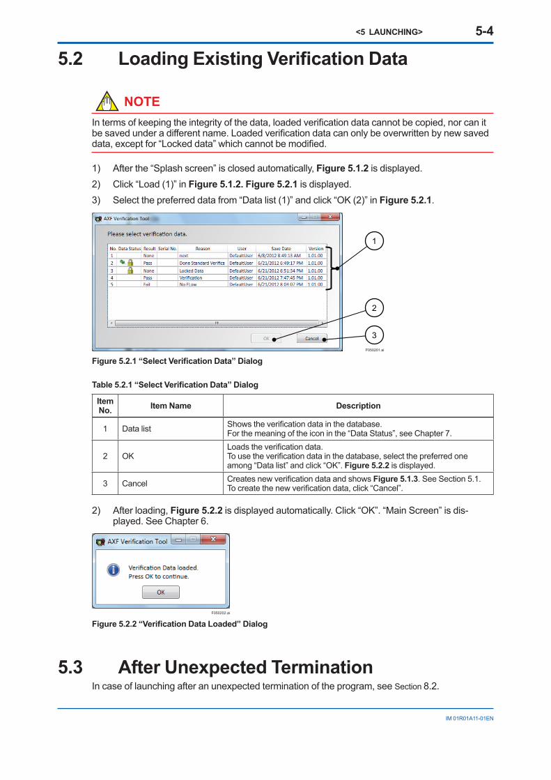
(A) Pulse Output (without optional code EM)1) WireAXFandCA150HandyCalibratororsimilarasshowninFigure 6.3.9.2) Select“100pps”in“SettingValue”.SeeFigure 6.3.7.
F060307.ai
Figure 6.3.7 “Setting Value” in “Pulse Output”
3) Output3)-1WhenVerificationToolisin“online”mode:
Select“Pulse”in“OutputSelection”andclick“Output”.SeeFigure 6.3.8
F060308.ai
Figure 6.3.8 “Output Selection” in “Pulse Output”
3)-2WhenVerificationToolisin“offline”mode:3)-2-1 RecordtheoriginalAXFparameters,andthensetthemasshownbelow.
Table 6.3.5 Parameter Settings of “Pulse Output”
HART Parameter Parameter of AXF Display Setting Value
PulseScale DeviceSetup→EasySetup→PulseScale B33/E11 100PulseWidth DeviceSetup→PulseSet→PulseWidth E12 50%DutyPulseUnit DeviceSetup→EasySetup→PulseScale B32/E10 Pulse/sTestDO(*1) DeviceSetup→Diag/Service→OutputTest→TestDO N30 Pulse
DOFunction(*1) DeviceSetup→Configuration→StatusFunction→DOFunction F20 PulseOutput
*1:OnlyforAXFA14orAXFIntegralFlowmeter
3)-2-2 OutputpulsebysettingAXFHARTparameter“Looptest”to“20mA”.
Table 6.3.6 Parameter Setting of “Pulse Output”
HART Parameter (DD) Parameter of AXF Display Setting Value
Looptest DeviceSetup→Diag/Service→OutputTest→Looptest - 20mA

<6 OPERATION> 6-29
IM 01R01A11-01EN
NOTE■ Measureformorethan60seconds.
■ IfusingaYOKOGAWACA150,setthemodeto“ContactInput”andtherangeto“CPM”.
4) Measurethepulseoutputvaluein“pps”withaYokogawaCA150HandyCalibratororequivalenttosimplifythemeasurementofpulses.Ifsuchadeviceisunavailable,anappro-priateload(30VDC,0.2Amax)isrequiredandusetheconfigurationshowninFigure 6.3.9.
SBBASACAL–AL+COMSO2+SO1+I+ I–CUR OUT STATUS OUT ALARM OUT SIGNAL
COMSI2+SI1+EX2EX1L/+N/–POWER SUPPLY EXCITER
P–P+PULSE OUT STATUS IN
Electronic Counter
30VDC , 0.2A. max
Externalpower supply
Load
Dashed box : Yokogawa CA150 Handy Calibrator or equivalentF060309-A.ai
(A) AXFA11 Remote Converter
Electronic Counter
30VDC , 0.2A. max
Externalpower supply
Load
Dashed box : Yokogawa CA150 Handy Calibrator or equivalentF060309-B.ai
(B) AXFA14 Remote Converter or AXF Integral Flowmeter
Figure 6.3.9 Pulse Output Diagram (without optional code EM)
5) Enterthemeasuredvaluemanually.6) “Result”isdisplayedautomatically.
F060310.ai
Figure 6.3.10 “Pulse Output” Result
7) Endprocessing7)-1WhenVerificationToolisin“online”mode:
Click“Exit”in“OutputSelection”.7)-2WhenVerificationToolisin“offline”mode:
SettheAXFparametersbacktotheiroriginalvaluesmanually.

<6 OPERATION> 6-30
IM 01R01A11-01EN
(B) Active Pulse Output (with optional code EM)1) WireAXFandCA150HandyCalibratororsimilarasshowninFigure 6.3.13.2) Select“2pps”in“SettingValue”.SeeFigure 6.3.11.
F060311.ai
Figure 6.3.11 “Setting Value” in “Active Pulse Output”
3) Output3)-1WhenVerificationToolisin“online”mode:
Select“Pulse”in“OutputSelection”andclick“Output”.SeeFigure 6.3.12.
F060312.ai
Figure 6.3.12 “Output Selection” in “Active Pulse Output”
3)-2WhenVerificationToolisin“offline”mode:3)-2-1 RecordtheoriginalAXFparameters,andthensetthemasshownbelow.
Table 6.3.7 Parameter Settings of “Active Pulse Output”
HART Parameter (DD) Parameter of AXF Display Setting Value
PulseScale DeviceSetup→EasySetup→PulseScale B33/E11 2PulseWidth DeviceSetup→PulseSet→PulseWidth E12 100msPulseUnit DeviceSetup→EasySetup→PulseScale B32/E10 Pulse/sTestDO(*1) DeviceSetup→Diag/Service→OutputTest→TestDO N30 Pulse
DOFunction(*1) DeviceSetup→Configuration→StatusFunction→DOFunction F20 PulseOutput
(*1)onlyforAXFA14orAXFIntegralFlowmeter
3)-2-2 OutputpulsebysettingAXFHARTparameter“Looptest”to“20mA”.
Table 6.3.8 Parameter Setting of “Active Pulse Output”
HART Parameter (DD) Parameter of AXF Display Setting Value
Looptest DeviceSetup→Diag/Service→OutputTest→Looptest - 20mA
NOTE• Measureformorethan60seconds.
• IfusingaYOKOGAWACA150,setthemodeto“Frequency(FREQ)andPulse”andtherangeto“CPM”.
• Anappropriateload(24VDC±20%,150mAmax)isrequired.

<6 OPERATION> 6-31
IM 01R01A11-01EN
4) Measurethepulseoutputvaluein“pps”withaYokogawaCA150HandyCalibratororequivalenttosimplifythemeasurementofpulses.Ifsuchadeviceisunavailable,usetheconfigurationshowninFigure 6.3.13.
SBBASACAL–AL+COMSO2+SO1+I+ I–CUR OUT STATUS OUT ALARM OUT SIGNAL
COMSI2+SI1+EX2EX1L/+N/–POWER SUPPLY EXCITER
P–P+PULSE OUT STATUS IN
Electronic Counter
Output voltage: 24 V DC ±20%Current: 150 mA max
Load
Dashed box : Yokogawa CA150 Handy Calibrator or similarF060313-A.ai
(A) AXFA11 Remote Converter
Electronic Counter
Output voltage: 24 V DC ±20%Current: 150 mA max
Load
Dashed box : Yokogawa CA150 Handy Calibrator or similar
F060313-B.ai
(B) AXFA14 Remote Converter or AXF Integral Flowmeter
Figure 6.3.13 Active Pulse Output Diagram (with optional code EM)
5) Enterthemeasuredvaluemanually.6) “Result”isdisplayedautomatically.
F060314.ai
Figure 6.3.14 “Active Pulse Output” Result
7) Endprocessing7)-1WhenVerificationToolisin“online”mode:
Click“Exit”in“OutputSelection”.7)-2WhenVerificationToolisin“offline”mode:
SettheAXFparametersbacktotheiroriginalvaluesmanually.

<6 OPERATION> 6-32
IM 01R01A11-01EN
6.3.3 Converter
WARNING
FollowUser’sManualFY2-XJAM012-40-2Eforcorrectoperationandsafehandling.
ThisitemcheckstheaccuracyoftheAXFconverterwithMagneticFlowmeterCalibratorAM012.
1 2 3
5
4
F060315.ai
Figure 6.3.15 “Converter” Screen
Table 6.3.9 Converter
Item No. Item Name Description
1 Connectiondiagram Showstheconnectiondiagramonanotherscreen.Thediagramis(A)or(B)inFigure 6.3.16 dependingonthecase.
2 Span ShowstheSpanoftheconverter.Thisfieldcanbeedited.
3 ReadSpan ReadstheSpanoftheconverter.Press“ReadSpan”.(OnlywhenVerificationToolisonlinetoAXF)
4 Measured(m/s) Showsthemeasuredvalue.Thisfieldcanbeedited.
5 Read Readsthemeasuredvalue.Press“Read”.(OnlywhenVerificationToolisonlinetoAXF)
SBBASACAL–AL+COMSO2+SO1+I+ I–CUR OUT STATUS OUT ALARM OUT SIGNAL
COMSI2+SI1+EX2EX1L/+N/–POWER SUPPLY EXCITER
P–P+PULSE OUT STATUS IN
(Shield) (White) (Black)
(Shield) (White) (Black)
AXFA11
AM012
F060316-A.ai
(A) AXFA11 Remote Converter
(Shield)
(White)
(Black)
(Shield)
(White)
(Black)
N /–L /+
SA
SB
+–+–+–
AM012
Junction Box Terminal
F060316-B.ai
(B) AXFA14 Remote Converter or AXF Integral Flowmeter
Figure 6.3.16 “Converter” Connection Diagram

<6 OPERATION> 6-33
IM 01R01A11-01EN
1) Fordetailsofthecalibrationprocedures,followUser’sManualFY2-XJAM012-40-2E. RecordthefollowingoriginalparametersandsettheAXFparametersasshownbelow
manually.(ThesesettingsaredescribedinFY2-XJAM012-40-2E.)
Table 6.3.10 AXF parameter setting of Converter Check
HART Parameter (DD) Parameter of AXF Display Setting Value
SelectFlowTube(*1)
Devicesetup→DetailedSetup→BasicSetup→Se-lectFlowTube C30 Calibrator
NominalSize Devicesetup→DetailedSetup→BasicSetup→NominalSize C32
Enterflowtubenominalsizein“mm”unit
NominalSize Devicesetup→DetailedSetup→BasicSetup→NominalSizeunit C31 mm
MFSet Devicesetup→DetailedSetup→BasicSetup→MFSet
C20(MeasureMode)
StandardDFor
EnhancedDF(*3)
LowMF Devicesetup→DetailedSetup→BasicSetup→MFSet→StandardDF→LowMF C21 1.0
HighMF Devicesetup→DetailedSetup→BasicSetup→MFSet→StandardDF→HighMF C22 1.0
LowMF(EDF)(*2)
Devicesetup→DetailedSetup→BasicSetup→MFSet→EnhancedDF→LowMF(EDF) C23 1.0
HighMF(EDF)(*2)
Devicesetup→DetailedSetup→BasicSetup→MFSet→EnhancedDF→HighMF(EDF) C24 1.0
*1: OnlyforAXFA11*2: OnlyforoptionalcodeHF1orHF2(EnhancedDualFrequencyExcitation)*3: OnlyforoptionalcodeHF1orHF2,select“EnhancedDF”.
2) Enterthespanonthe“Converter”screen.2)-1WhenVerificationToolisin“online”mode:
Click“ReadSpan(3)”inFigure 6.3.15.Thevalueofparameter“VelocityCheck”isenteredautomatically.IftheAXFparametersaredifferentfromthoseinTable 6.3.10,thefollowingerrormessageisdisplayed.SettheAXFparameterstothoseinTable 6.3.10.
F060317.ai
Figure 6.3.17 Example of “Parameter Error” Dialog

<6 OPERATION> 6-34
IM 01R01A11-01EN
2)-2WhenVerificationToolisin“offline”mode: Readthevalueofparameter“VelocityCheck”manually.RefertoTable 6.3.11. And enter thevaluein“cell(2)”inFigure 6.3.15manually.
Table 6.3.11 AXF Parameter Settings of Converter Check
HART Parameter (DD) Parameter of AXF Display
VelocityCheck Devicesetup→DetailedSetup→BasicSetup→VelocityCheck C44
3) Measuretheoutputaccuracyatthepreferredsetting(0%,25%,50%,75%,or100%).Aftersettingthevalue,lettheAM012stabilizeatleastfor1minute.
Foroperationprocedure,followUser’sManualFY2-XJAM012-40-2E.4) Enterthemeasuredvalue.4)-1WhenVerificationToolisin“online”mode:
Click“Read(5)”inFigure 6.3.15.Thevalueofinstantaneousflowrateisenteredautomati-cally.
4)-2WhenVerificationToolisin“offline”mode: Readthevalueofparameter“PV”or“PV%rnge”manually.RefertoTable 6.3.12,andconvertthevaluein“m/s”unit.
Enterthecalculatedvaluein“cell(4)”inFigure 6.3.15manually.
Table 6.3.12 AXF Measured Value of “Converter” Check
HART Parameter (DD) Parameter of AXF Display
PV■ProcessVariables→PVor■DeviceStatus→ProcessVariable→PV
A20
PV%rnge■ProcessVariables→PV%rngeor■DeviceStatus→ProcessVariable→PV%rnge
A10
5) “Error(%)”iscalculatedautomatically.6) “Result”isdisplayedautomaticallyafterfillinginallfields.
F060318.ai
Figure 6.3.18 “Converter” Result
7) SettheAXFparametersbacktotheiroriginalvaluesmanually.

<6 OPERATION> 6-35
IM 01R01A11-01EN
6.3.4 Insulation Resistance
WARNING
FollowUser’sManualIM01E20D01-01Eforcorrectoperationalandsafehandling.Wheretheinsulationresistancecheckisnotpossible,select“N/A”
1) Checktheinsulationresistanceintheterminalboxinaccordancewiththetablesbelow.Fol-lowUser’sManualIM01E20D01-01E.
(A) Coil
Table 6.3.13 Coil Insulation Resistance Check
Test Terminals Test VoltageBetweenterminalsEX1andC 500VDC(Useaninsulationtesterorequivalent.)
(B) Signal (Electrode)
Table 6.3.14 Electrode Insulation Resistance Check
Test Terminals Test Voltage- BetweenterminalsAandC- BetweenterminalsBandC 500VDC(Useaninsulationtesterorequivalent.)
2) Enterthemeasuredvaluemanually. Wheretheinsulationresistancecheckisnotpossible,select“N/A”. Wherethemeasuredvalueisover-range,select“OpenLoop(O.L.)”.
3) “Result”isdisplayedautomatically.
F060319-A.ai
(A) Example 1
F060319-B.ai
(B) Example 2Figure 6.3.19 “Insulation Resistance” Result

<6 OPERATION> 6-36
IM 01R01A11-01EN
6.4 ResultTheresultsofStandardVFandEnhancedVFareavailableinthe“Result”tab.Uncompletedcheckitemsaredisplayedasblank.
F060401.ai
Figure 6.4.1 “Result” Screen

<6 OPERATION> 6-37
IM 01R01A11-01EN
TheresultinfullviewisshownFigure 6.4.2.Iftheuserneedsahardcopyofthereport,refertoSubsection6.1.3.
1
2
3
4
5
F060402.ai6
Figure 6.4.2 “Result” in Full View

<6 OPERATION> 6-38
IM 01R01A11-01EN
Table 6.4.1 Result
Item No. Item Name Description
1
Tag(Converter)Tag(Flowtube)SerialNo.(Converter)SerialNo.(Flowtube)
ShowsAXFdeviceinformation.ThecontentsenteredinGeneralInforma-tionaredisplayedbydefault.Thisfieldscanbeeditedinthe“Result”tab.
2 OverallStatus
Showstheresultofthewholeverification.
• PassedThisflowmeterwasverifiedtobefunctioningwithin+/-□%oftheoriginalfactorycalibration.• FailedThisflowmeterdidnotpasstheverificationtest.
3 Comments Showsusercomment.Thisitemcanbeedited.Enteranycomment(e.g.user’sdocumentNo.).
4 VerifiedbyShowsthenameofthepersonwhoperformedtheverification.ThenameenteredinGeneralInformationisdisplayedbydefault.Thisfieldcanbeeditedinthe“Result”tab.
5 Signature Showsthesignatureofthepersonwhoperformedtheverification.Thepersonshouldsignthisfieldontheprintout.
6 LegendsymbolsShowsthemeaningofsymbolsin“Result”fields.●[----]:Inconclusive●[ ]:Notperformed

<7 VARIATION OF VERIFICATION DATA> 7-1
IM 01R01A11-01EN
7 VARIATION OF VERIFICATION DATAIntermsofkeepingitsowndataintegrity,verificationdatacannotbecopied,norcanitbesavedasothername.Verificationdataexceptfor“Lockeddata”canbesavedonlybynewlysavingorover-writing.Thereare3typesofverificationdata:1. Installationdata2. Lockeddata3. Others
3
2
1
F070101.ai
Figure 7.1.1 Variation of verifi cation data
Table 7.1.1 Variation of verifi cation data
Item No. Item Name Icon Description
1 Installationdata SeeSection7.1.
2 Lockeddata SeeSection7.1andSection7.2.
3 Others SeeSection7.3.
7.1 Installation Data“Installationdata”functionsasareference.Eachdevicecanhaveonlyone“Installationdata”.Whentheverificationdataissavedbycheckingthe“Saveasinstallationdata”boxinFigure 6.1.9,thedatabecomesthe“Installationdata”.Onlywhen“NoFlow+Flow(*1)”iscomplete,verificationdatacanbesavedasan“Installationdata”.SeeSubsection6.1.2.Savethefirstverificationdataafterthedeliveryas“Installationdata”.(Recommended)Whentheuserwantstoedit“Installationdata”later:
Savetheverificationdatabycheckingonlythe“Savedasinstallationdata”boxinFigure 6.1.9.TheiconinDataStatusis“ “.
Whenitisnecessarytosaveinstallationdataasread-only:Savetheverificationdatabycheckingthe“Savedasinstallationdata”boxandthe“Saveaslockeddatabox”inFigure 6.1.9.TheiconinDataStatusis“ ”.
*1:“NoFlow+Flow”:“Circuit”checkand“DeviceStatus”checkforboth“NoFlow”and“Flow”conditions.RefertoSubsection6.2.1.

<7 VARIATION OF VERIFICATION DATA> 7-2
IM 01R01A11-01EN
7.2 Locked Data“Lockeddata”issavedasread-only.TheiconinDataStatusis“ ”.Afterverificationdataissavedas“Lockeddata”,thedata:• canbeloaded.
• canbeprintedout.
• cannotbeover-written.
Whenverificationiscomplete,savetheverificationdataas“Lockeddata”topreventunexpectedover-writingorfalsifying,beforeprinting.(Recommended)
7.3 OthersVerificationdatawhichisneither“Installationdata”nor“Lockeddata”canbeedited.Whenverifi-cationistobecontinuedlater,donotsaveaseither“Installationdata”or“Lockeddata”.

<8 TERMINATION> 8-1
IM 01R01A11-01EN
8 TERMINATIONThischapterdescribes“NormalTermination”and“UnexpectedTermination”.
IMPORTANTMakesuretokeeptheAXF’spoweronatleastfor10minutesafteryoufinishtheVerificationTool.Ifyouturnthepoweroffimmediately,someoftheparametersmaybechangedtodifferentvaluesfromoriginalsetting.
8.1 Normal TerminationSelect“File”-“Exit”orclickthe“Close”buttonattheupper-rightcornerof“MainScreen”.
F080101.ai
Figure 8.1.1 Normal Termination
8.1.1 When the verification data has not been changed after saving:
Thistoolisterminatedwithoutanydialogsappearing.
8.1.2 When the verification data has been changed after saving:
1) Figure 8.1.2isdisplayed.
1
2
F080102.ai
Figure 8.1.2 “Confirmation” Dialog
Table 8.1.1 “Confirmation” Dialog
Item No. Item Name Description
1 Yes Savestheverificationdatabyover-writing.SeeSubsection6.1.2.2 No Cancelssavingthedata.
<8 TERMINATION> 8-2
IM 01R01A11-01EN
2) Selectwhetherthelatestverificationdataissavedtothedatabaseornot.2)-1 Tosavethelatestverificationdata:
Select“Yes(1)”.SeeSubsection6.1.2.2)-2Whenthelatestverificationdataisnotsaved:
Select“No(2)”.Nodialogsappearandthedataisnotsaved.3) ThisVerificationToolisterminatedautomatically.
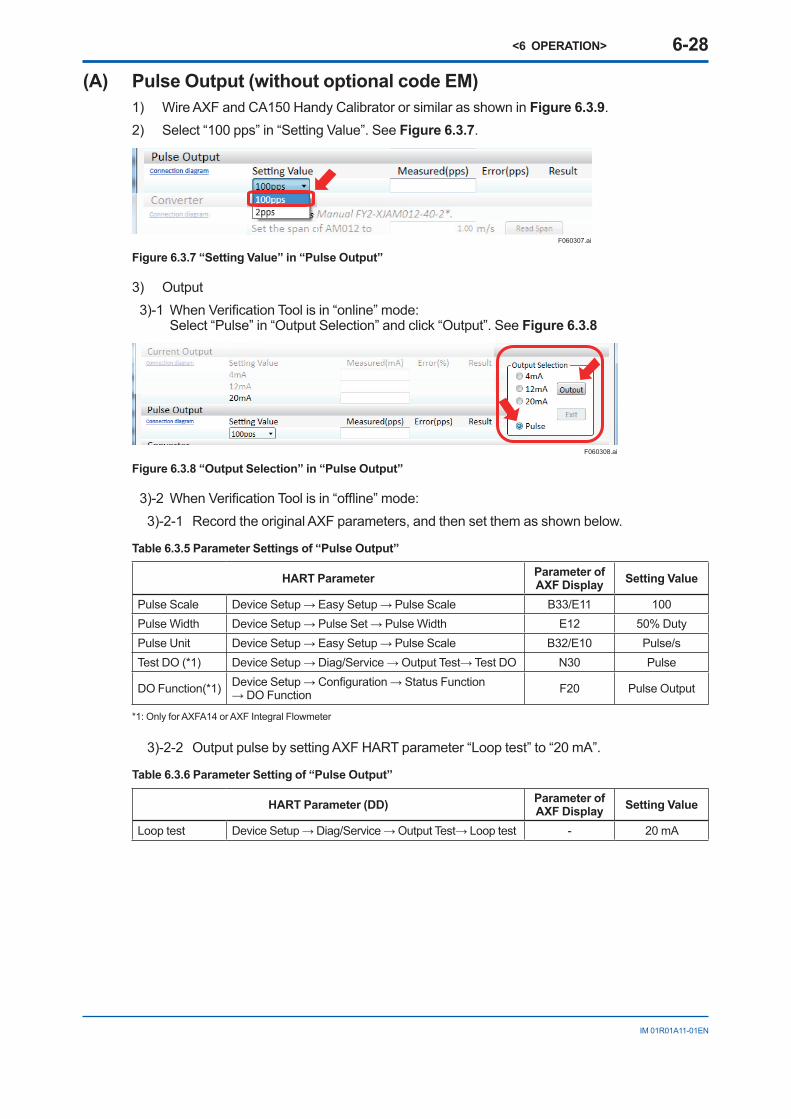
8.2 Unexpected TerminationIfanunexpectedterminationoccurs,followthisprocedure.1) Whenanunexpectedterminationoccurs,besuretore-connectFieldMateandAXF,and
rebootVerificationTool.IftheAXFparametershavebeenchangedfromtheoriginalsetting,Figure 8.2.1 “Error Recovery” Dialogisdisplayedafterreboot.
1
2
F080201.ai
Figure 8.2.1 “Error Recovery” Dialog
Table 8.2.1 “Error Recovery” Dialog
Item No. Item Name Description
1 Errorcontents Shows“Lastverificationerrordate”and“Parameteritemswhichwillberecovered”.
2 OK ResetstheAXFinternalparameterstotheiroriginalvalues.Click“OK(2)”.
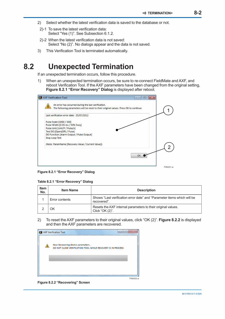
2) ToresettheAXFparameterstotheiroriginalvalues,click“OK(2)”.Figure 8.2.2isdisplayedandthentheAXFparametersarerecovered.
F080202.ai
Figure 8.2.2 “Recovering” Screen

<9 COMMUNICATION ERROR> 9-1
IM 01R01A11-01EN
9 COMMUNICATION ERROR
9.1 Error MessageThischaptershowserrordialogs.SeeTable 9.1.1fordetails.Aftertermination,followSection8.2.
F090101.ai
Figure 9.1.1 Error Dialog 1
F090102.ai
Figure 9.1.2 Error Dialog 2
F090103.ai
Figure 9.1.3 Error Dialog 3
F090104.ai
Figure 9.1.4 Error Dialog 4

<9 COMMUNICATION ERROR> 9-2
IM 01R01A11-01EN
F090105.ai
Figure 9.1.5 Error Dialog 5
Table 9.1.1 Communication Error Dialog
Figure No. Message When Description
9.1.1
Setting Error.Setthedeviceaddressto0,andthenrestartthisapplica-tion.
■WhenstartingVerifica-tionToolfrom“SegmentViewer”withstatuswhereFieldMateisonlinetoAXFwhosedeviceaddressisnot“0”.
■IftheuserwantstorunVerifi-cationToolwithstatuswhereVeri-ficationToolisin“online”mode: FollowSection9.2.
■IfVerificationToolneednotbein“online”mode: RestartVerificationToolfrom“DeviceNavigator”,“DeviceInfo”,or“History”.
9.1.2
Erroroccurredduringverifica-tion.Applicationhasterminated.Checkconnectionsandthenrestartthisapplication.PressOKtocontinue.
■Duringrunning“Circuit”checkor“DeviceSta-tus”check.
■Duringsettingpulseoutput.
Afterthisdialog,Figure 8.1.2isdis-playedandthetoolisterminated.AsAXFparametersmighthavechanged,followSection8.2.
9.1.3
Deviceparametershavebeenchanged.Checkconnectionsandthenrestartthisapplication.PressOKtocontinue.
■Duringrunning“Cur-rentOutput”or“PulseOutput”.
Afterthisdialog,Figure 8.1.2isdis-playedandthetoolisterminated.AsAXFparametersmighthavechanged,followSection8.2.
9.1.4ConnectionError.Checkconnections.PressOKtocontinue.
■Duringpreparing“Cir-cuit”checkor“DeviceStatus”checkafterclick-ing“StartVerification”inStandardVF.
Uponclicking;■“Output”inOutputSe-lection
■“Exit”inOutputSelec-tion
■“ReadSpan”inCon-verter
■“Yes”inFigure 8.2.1.
Afterthisdialog,thetoolreturnstothepreviousstep.
9.1.5
ConnectionError.Checkconnectionsandthenrestartthisapplication.PressOKtocontinue.
■Duringlaunching“Verifi-cationTool”
■DuringrecoveryofAXFparametersafterunexpectedtermination(Figure 8.2.2)
Afterthisdialog,thetoolistermi-nated.AsAXFparametersmighthavechanged,followSection8.2.

<9 COMMUNICATION ERROR> 9-3
IM 01R01A11-01EN
9.2 Device Address Setting
WARNING
Thisoperationmustbecarriedoutbythetrainedpersonnelhavingknowledgeofmultidroploop.Forthedetailsoftheparametersettingprocedure,refertoIM01E20C01-01EorIM01E20C02-01E.AfterusingVerificationTool,settheAXFtotheoriginalmultidroploop.
9.2.1 Multidrop Mode Canceling
F090201-A.ai
USB FieldMate Modem
Device ADevice Address: 1
Device BDevice Address: 2
Device CDevice Address: 3
Device XDevice Address: 15
Load: 250 Ω+
-
+
-
+
-
+
-
USB FieldMate Modem
Device ADevice Address: 1
Load: 250 Ω
Load:250 Ω
Multidrop Loop side
+
-
Set to “0”.
F090201-B.ai
(A) Multidrop loop (B) After canceling Multidrop loop
Figure 9.2.1 Configuration
1) Disconnectthetargetdevice(AXF)fromthemultidroploopphysically.2) ConnecttheAXFtoFieldMateonetoone.Aloadof250Ωisrequired.SeeFigure 9.2.1 (B).3) RecordthefollowingoriginalAXFparameter,andthensettheparameterasshown.
Table 9.2.1 Parameter of Cancelling Multidrop mode
HART Parameter (DTM) Setting ValuePollAddr Configuration→HART→Polladdr 0
4) StartVerificationTool.
9.2.2 Multidrop Mode SettingAfterusingVerificationTool,settheAXFbacktoitsoriginalstatus.1) AfterVerificationTooltermination,settheAXFparameterbacktoitsoriginalvaluemanually.
Table 9.2.2 Parameter Setting of Multidrop mode
HART Parameter (DTM) Setting ValuePollAddr Configuration→HART→Polladdr OriginalValue
2) ConnecttheAXFbacktotheoriginalconfiguration.

IM 01R01A11-01EN
Revision InformationAXFVerificationToolManualNo.: IM01R01A11-01EN
Edition Date Page RevisedItem1st Aug. 2012 - Newpublication2nd Oct.2014
2-22-44-1
4-2 to 4-3
4-4 to 4-5
4-6
6-128-1
SoftwareupdatesforFieldMatefromR2.05toR3.012.1 CorrectedtheFigure2.1.12.3 CorrectedtheFigure2.3.14 CorrectedtheFigure4.1.14.1 ChangedtheFigure4.1.2andFigure4.1.3 AddedtheFigure4.1.44.2 ChangedtheFigure4.2.1andFigure4.2.2 AddedtheFigure4.2.34.3 ChangedtheSection4.3 DeletedtheSection4.46.2.1 AddedtheIMPORTANT8 AddedtheIMPORTANT
3rd Aug. 20162-2
4-2 to 4-34-4 to 4-5
4-6
SoftwareupdatesforFieldMatefromR3.01toR3.022.1 ChangedtheFigure2.1.14.1 ChangedtheFigure4.1.2toFigure4.1.44.2 ChangedtheFigure4.2.1toFigure4.2.34.3 ChangedtheFigure4.3.1