IM 1E7B0-02E - Yokogawa
102
User's Manual Models AE100, AE200 and AE300 Integral Type Magnetic Flowmeter [Style S1:AE***SC] [Style S2:AE***M*] IM 1E7B0-02E IM 1E7B0-02E 16th Edition Yokogawa Electric Corporation
-
Upload
khangminh22 -
Category
Documents
-
view
0 -
download
0
Transcript of IM 1E7B0-02E - Yokogawa

User'sManual
Models AE100, AE200 and AE300Integral Type Magnetic Flowmeter[Style S1:AE***SC]
[Style S2:AE***M*] IM 1E7B0-02E
IM 1E7B0-02E 16th Edition
Yokogawa Electric Corporation
i
CONTENTS
FD No. IM 1E7B0-02E16th Edition: Dec. 2003(YK)All Rights Reserved, Copyright © 1994, Yokogawa Electric Corporation
Contents
1. INTRODUCTION ................................................................................................... 1-1
2. HANDLING PRECAUTIONS ............................................................................... 2-1
2.1 Checking Model and Specifications .............................................................. 2-12.2 Accessories .................................................................................................... 2-12.3 Storage Precautions ........................................................................................ 2-12.4 Installation Location Precautions ................................................................... 2-12.5 Converter Reorientation Precautions ............................................................. 2-1
3. COMPONENT NAMES ......................................................................................... 3-1
4. INSTALLATION ..................................................................................................... 4-1
4.1 Piping Design Precautions ............................................................................. 4-14.2 Handling Precautions ..................................................................................... 4-3
4.2.1 General Precautions ................................................................................ 4-34.2.2 Flow Tube Piping .................................................................................... 4-44.2.3 Alteration of LCD Display Orientation................................................... 4-4
4.3 Mounting ........................................................................................................ 4-54.3.1 Nominal Diameter 2.5 mm (0.1in.) to 10 mm (0.4in.) Union Joint Type 4-54.3.2 Nominal Diameter 2.5mm (0.1in.) to 40mm (1.5in.) Wafer Type .......... 4-64.3.3 Nominal Diameter 50 mm(2in.) to 300 mm(12in.) Wafer Type ............. 4-94.3.4 Nominal Diameter 15 mm (0.5in.) to 400 mm (16in.) Flange Type ..... 4-124.3.5 Mounting Procedure for Sanitary Type ................................................. 4-14
4.4 Wiring Precautions ....................................................................................... 4-144.4.1 Protective Grounding ............................................................................ 4-144.4.2 General Precautions .............................................................................. 4-154.4.3 Power and Output Cables ...................................................................... 4-154.4.4 DC Connections .................................................................................... 4-154.4.5 Wiring Ports .......................................................................................... 4-154.4.6 Connecting to External instruments ...................................................... 4-16
5. BASIC OPERATING PROCEDURES.................................................................. 5-1
5.1 Liquid Crystal Display ................................................................................... 5-15.2 Types of Display Data .................................................................................... 5-2
5.2.1 Flow Rate Data Display Mode ................................................................ 5-35.2.2 Setting Mode ........................................................................................... 5-65.2.3 Alarm Display Mode ............................................................................... 5-9
6. FUNCTION AND DATA SETTINGS .................................................................... 6-1
6.1 Setting Flow Span .......................................................................................... 6-16.2 Power Frequency ............................................................................................ 6-46.3 Other Functions and Settings ......................................................................... 6-4
6.3.1 Pulse Output ............................................................................................ 6-46.3.2 Display of Internal Totalization Values ................................................... 6-66.3.3 Resetting for Totalization Display ........................................................... 6-76.3.4 Damping Time Constant ......................................................................... 6-7
ii
CONTENTS
IM 1E7B0-02E
6.3.5 Limiting Current Output During Alarm Occurrence ............................... 6-86.3.6 Reversing Flow Direction ...................................................................... 6-86.3.7 Limiting on Current Output .................................................................... 6-86.3.8 Forward and Reverse Flow Measurement ............................................. 6-106.3.9 Automatic Two Range Switching.......................................................... 6-116.3.10 Alarm Output at Low Flow Limit (Flow Switch) ................................. 6-126.3.11 Totalization Switch Output .................................................................... 6-136.3.12 Alarm Output ........................................................................................ 6-146.3.13 Data Setting Enable / Inhibit ................................................................. 6-146.3.14 Procedure of Selecting Special Application Items ................................ 6-156.3.15 Rate Limit .............................................................................................. 6-156.3.16 Pulsating Flow ....................................................................................... 6-16
7. OPERATION VIA BRAIN TERMINAL .............................................................. 7-1
7.1 Operation Via the BT200 ............................................................................... 7-17.1.1 BT200 Connections ................................................................................. 7-17.1.2 BT200 Keypad Layout ............................................................................ 7-27.1.3 Major BT200 Key Functions ................................................................... 7-37.1.4 Displaying Flow Rate Data ..................................................................... 7-5
7.2 Setting Parameters ......................................................................................... 7-67.2.1 Setting Flow Span ................................................................................... 7-67.2.2 Power Frequency ..................................................................................... 7-77.2.3 Pulse Output (Refer to 6.3.1) .................................................................. 7-77.2.4 Display of Internal Totalization Values (Refer to 6.3.2) ......................... 7-87.2.5 Resetting for Totalization Display (Refer to 6.3.3) ................................. 7-87.2.6 Damping Time Constant (Refer to 6.3.4) ................................................ 7-97.2.7 Current Output during Alarm Occurrence (Refer to 6.3.5) ..................... 7-97.2.8 Reversing Flow Direction (Refer to 6.3.6) .............................................. 7-97.2.9 Limiting Current Output (Refer to 6.3.7) ................................................ 7-97.2.10 Forward and Reverse Flow Measurement (Refer to 6.3.8) ................... 7-107.2.11 Automatic Two Range Switching (Refer to 6.3.9) ................................ 7-117.2.12 Alarm Output at Low Flow Limits (Flow Switch) (Refer to 6.3.10) .... 7-117.2.13 Totalization Switch Output (Refer to 6.3.11) ....................................... 7-127.2.14 Alarm Output (Refer to 6.3.12) ............................................................. 7-127.2.15 Data Setting Enable / Inhibit (Refer to 6.3.13) ..................................... 7-137.2.16 Procedure of Selecting Special Application Items (Refer to 6.3.14) .... 7-137.2.17 Rate Limit (Refer to 6.3.15) .................................................................. 7-137.2.18 Pulsating Flow (Refer to 6.3.16) ........................................................... 7-137.2.19 User-Defined Units Via the BT200 ....................................................... 7-147.2.20 Other Important Points to Note ............................................................. 7-15
8. ACTUAL OPERATION .......................................................................................... 8-1
8.1 Pre-Operation Zero Adjustment ..................................................................... 8-18.1.1 Zero Adjustment Using Data Setting Keys ............................................. 8-18.1.2 Zero Adjustment Via the BT200 ............................................................. 8-2
8.2 Self-diagnostics Functions ............................................................................. 8-38.2.1 Display and Output Status during Alarm Occurrence ............................. 8-38.2.2 Error Description and Countermeasures ................................................. 8-3

iii
CONTENTS
IM 1E7B0-02E
9. MAINTENANCE .................................................................................................... 9-1
9.1 Loop Test (Test Output) ................................................................................. 9-19.1.1 Settings for Test Output Using Data Setting Keys .................................. 9-19.1.2 Setting for Test Output Via the BT200 .................................................... 9-1
9.2 Fuse Replacement .......................................................................................... 9-29.3 Trouble Shooting ............................................................................................ 9-2
10. OUTLINE............................................................................................................... 10-1
11. PARAMETER SUMMARY ................................................................................. 11-1
12. EXPLOSION PROTECTED TYPE INSTRUMENT ........................................ 12-1
12.1 CENELEC ATEX (KEMA) ......................................................................... 12-112.2 FM ................................................................................................................ 12-212.3 CSA .............................................................................................................. 12-312.4 SAA.............................................................................................................. 12-312.5 TIIS(JIS) ...................................................................................................... 12-4
13. PRESSURE EQUIPMENT DIRECTIVE ........................................................... 13-1
INSTALLATION AND OPERATING PRECAUTIONS FOR TIIS(JIS) FLAMEPROOFEQUIPMENT ......................................................................................................... EX-B03E

IM 1E7B0-02E1-1
1. INTRODUCTION
1. INTRODUCTION
This instrument has been already adjusted at thefactory before shipment.
To ensure correct use of the instrument, please readthis manual thoroughly and fully understand how tooperate the instrument before operating it.
Regarding This Manual• This manual should be passed on to the end user.• Before use, read this manual thoroughly to compre-
hend its contents.• The contents of this manual may be changed
without prior notice.• All rights reserved. No part of this manual may be
reproduced in any form without Yokogawa’s writtenpermission.
• Yokogawa makes no warranty of any kind withregard to this material, including, but not limited to,implied warranties of merchantability and suitabilityfor a particular purpose.
• All reasonable effort has been made to ensure theaccuracy of the contents of this manual. However, ifany errors are found, please inform Yokogawa.
• Yokogawa assumes no responsibilities for thisproduct except as stated in the warranty.
• If the customer or any third party is harmed by theuse of this product, Yokogawa assumes no responsi-bility for any such harm owing to any defects in theproduct which were not predictable, or for anyindirect damages.
Safety Precautions• The following general safety precautions must be
observed during all phases of operation, service, andrepair of this instrument. Failure to comply withthese precautions or with specific WARNINGSgiven elsewhere in this manual violates safetystandards of design, manufacture, and intended useof the instrument. YOKOGAWA Electric Corpora-tion assumes no liability for the customer’s failure tocomply with these requirements. If this instrument isused in a manner not specified in this manual, theprotection provided by this instrument may beimpaired.
The following safety symbol marks are used inthis manual and instrument;
WARNING
A WARNING sign denotes a hazard. It callsattention to procedure, practice, condition or thelike, which, if not correctly performed or adheredto, could result in injury or death of personnel.
CAUTION
A CAUTION sign denotes a hazard. It callsattention to procedure, practice, condition or thelike, which, if not correctly performed or adheredto, could result in damage to or destruction ofpart or all of the product.
IMPORTANT
A IMPORTANT sign denotes an attention toavoid leading to damage to instrument or systemfailure.
NOTE
A NOTE sign denotes a information for essentialunderstanding of the operation and features.
Protective grounding terminal.
Function grounding terminal. This terminalshould not be used as a “Protective groundingterminal”.
Alternating current.
Direct current.

IM 1E7B0-02E1-2
1. INTRODUCTION
Warranty• The guaranteed term of this instrument is described
in the quotation. We repair the damages thatoccurred during the guaranteed term for free.
• Please contact with our sales office when thisinstrument is damaged.
• If the instrument has trouble, please inform usmodel code, serial number, and concrete substancesor situations. It is preferable to be attached a outlineor data.
• We decide after the examination if free repair isavailable or not.
• Please consent to the followings for causes ofdamages that are not available as free repair, even ifit occured during the guaranteed term.
A: Unsuitable or insufficient maintenance by thecustomer.
B: The handling, using, or storage that ignore thedesign and specifications of the instrument.
C: Unsuitable location that ignore the description inthis manual.
D: Remaking or repair by a person except whom weentrust.
E: Unsuitable removing after delivered.F: A natural disaster (ex. a fire, earthquake, storm and
flood, thunderbolt) and external causes.
For Safety UsingFor safety using the instrument, please give attentionmentioned below.
WARNING
(1) Installation• The instrument must be installed by expert
engineer or skilled personnel. The proceduresdescribed about INSTALLATION are notpermitted for operators.
• The Magnetic Flowmeter is a heavy instrument.Please give attention to prevent that personsare injured by carrying or installing. It is prefer-able for carrying the instrument to use a cartand be done by two or more persons.
• In case of high process temperature, careshould be taken not to burn yourself becausethe surface of body and case reach a hightemperature.
• When removing the instrument from hazardousprocesses, avoid contact with the fluid and theinterior of the flow tube.
• All installation shall comply with local install-ation requirement and local electrical code.
(2) Wiring• The instrument must be installed by expert
engineer or skilled personnel. The proceduresdescribed about WIRING are not permitted foroperators.
• Please confirm voltages between the powersupply and the instrument before connectingthe power cables. And also, please confirmthat the cables are not powered beforeconnecting.
• The protective grounding must be connected tothe terminal in order to avoid personalshock hazard.
(3) Operation• Wait 10 min. after power is turned off, before
opening the covers.(4) Maintenance• Please do not carry out except being written to
a maintenance descriptions. When theseprocedures are needed, please contact tonearest YOKOGAWA office.
• Care should be taken to prevent the build up ofdrift, dust or other material on the display glassand data plate. In case of its maintenance, softand dry cloth is used.
(5) Explosion Protected Type Instrument• For explosion proof type instrument, the
description in Chapter 12 “EXPLOSIONPROTECTED TYPE INSTRUMENT” is prior tothe other description in this user's manual.
• Only trained persons use this instrument in theindustiral location.
• The protective grounding must be con-nected to a suitable IS grounding system.
• Take care not to generate mechanical sparkwhen access to the instrument and peripheraldevices in hazardous locations.
(6) The Instrument in Compliance with PED• For the instrument in compliance with PED, the
description in Chapter 13 “PRESSURE EQUIP-MENT DIRECTIVE” is prior to the other de-scription in this User’s Manual.

IM 1E7B0-02E1-3
1. INTRODUCTION
ATEX DocumentationThis procedure is only applicable to the countries inEuropean Union.
GB
All instruction manuals for ATEX Ex related productsare available in English, German and French. Shouldyou require Ex related instructions in your locallanguage, you are to contact your nearest Yokogawaoffice or representative.
DK
Alle brugervejledninger for produkter relateret tilATEX Ex er tilgængelige på engelsk, tysk og fransk.Skulle De ønske yderligere oplysninger om håndteringaf Ex produkter på eget sprog, kan De rettehenvendelse herom til den nærmeste Yokogawaafdeling eller forhandler.
I
Tutti i manuali operativi di prodotti ATEXcontrassegnati con Ex sono disponibili in inglese,tedesco e francese. Se si desidera ricevere i manualioperativi di prodotti Ex in lingua locale, mettersi incontatto con l’ufficio Yokogawa più vicino o con unrappresentante.
E
Todos los manuales de instrucciones para los productosantiexplosivos de ATEX están disponibles en inglés,alemán y francés. Si desea solicitar las instrucciones deestos artículos antiexplosivos en su idioma local,deberá ponerse en contacto con la oficina o elrepresentante de Yokogawa más cercano.
NL
Alle handleidingen voor producten die te makenhebben met ATEX explosiebeveiliging (Ex) zijnverkrijgbaar in het Engels, Duits en Frans. Neem,indien u aanwijzingen op het gebied vanexplosiebeveiliging nodig hebt in uw eigen taal, contactop met de dichtstbijzijnde vestiging van Yokogawa ofmet een vertegenwoordiger.
SF
Kaikkien ATEX Ex -tyyppisten tuotteiden käyttöhjeetovat saatavilla englannin-, saksan- ja ranskankielisinä.Mikäli tarvitsette Ex -tyyppisten tuotteiden ohjeitaomalla paikallisella kielellännne, ottakaa yhteyttälähimpään Yokogawa-toimistoon tai -edustajaan.
P
Todos os manuais de instruções referentes aos produtosEx da ATEX estão disponíveis em Inglês, Alemão eFrancês. Se necessitar de instruções na sua línguarelacionadas com produtos Ex, deverá entrar emcontacto com a delegação mais próxima ou com umrepresentante da Yokogawa.
F
Tous les manuels d’instruction des produits ATEX Exsont disponibles en langue anglaise, allemande etfrançaise. Si vous nécessitez des instructions relativesaux produits Ex dans votre langue, veuillez biencontacter votre représentant Yokogawa le plus proche.
D
Alle Betriebsanleitungen für ATEX Ex bezogeneProdukte stehen in den Sprachen Englisch, Deutschund Französisch zur Verfügung. Sollten Sie dieBetriebsanleitungen für Ex-Produkte in IhrerLandessprache benötigen, setzen Sie sich bitte mitIhrem örtlichen Yokogawa-Vertreter in Verbindung.
S
Alla instruktionsböcker för ATEX Ex (explosionssäkra)produkter är tillgängliga på engelska, tyska ochfranska. Om Ni behöver instruktioner för dessaexplosionssäkra produkter på annat språk, skall Nikontakta närmaste Yokogawakontor eller representant.
GR
ATEX Ex , . Ex
Yokogawa .

IM 1E7B0-02E2-1
2. HANDLING PRECAUTIONS
2. HANDLING PRECAUTIONS
This instrument has been already tested thoroughly atthe factory. When the instrument is delivered, pleasecheck externals and make sure that no damageoccurred during transportation.
In this chapter, handling precautions are described.Please read this chapter thoroughly at first. And pleaserefer to the relative matter about other ones.
If you have any problems or questions, please makecontact with Yokogawa sales office.
2.1 Checking Model andSpecifications
The model and specifications are shown on the DataPlate. Please confirm the specifications between theinstrument that was delivered and the purchase order(refer to the chapter 10. Outline).
Please let us know Model and Serial No. when makingcontact with Yokogawa sales office.
MAGNETIC FLOW DETECTOR
Made In Japan
MODELSUFFIX
PULSEOUTPUTLININGMATERIALELECTRODEMATERIALACCURACYRATINGFLUID TEMP.FLUID PRESS.AMB.TEMP.NO.
STYLESIZEMETERFACTORSUPPLY
FULL SCALECURRENTOUTPUT
mm
VDC 0.2Amax
(JIS B7554) °C MAX. (SEE IM)
+60°C MAX. (SEE IM)-0.1 MPa MIN. (SEE IM)
LH
VDC 12.5WVAC 47-63Hz 36VA 12.5W
mA(0-750Ω)
IM: User’s Manual N200
Figure 2.1 Data Plate
2.2 AccessoriesWhen the instrument is delivered, please make surethat the following accessories are in the package.
Spare fuse can be applied only to this product.
• Fuse (250V,2A time lag) : 1-piece*The spare fuse is taped to the converter.
• Data sheet : 1-sheet• Unit labels : 1-sheet• Centering device (for wafer type) : 1-set• Plug (for DC power supply only) : 1-piece• Hexagonal wrench : 1-piece
(for special screw of hazardous duty type converter.)
2.3 Storage PrecautionsIn case the instrument is expected to be stored over along term, please give attention to the followings;
• The instrument should be stored in its originalpacking condition.
• The storage location should be selected according tothe following conditions:1) The location where it is not exposed to rain or
water.2) The location where there is few vibration or
shock.3) Temperature and humidity should be:
Temperature: –20 to 60˚C (–4 to 140˚F)Humidity: 5 to 80% RH (no condensation)Preferable ambient temperature and humidityare 25˚C(77˚F) and about 65% RH.
2.4 Installation LocationPrecautions
Please select the installation location considering thefollowing items to ensure long term stable operation ofthe flow tube.
• Ambient Temperature:Please avoid to install the instrument at the locationwhere temperature changes continuously. If thelocation receives radiant heat from the plant, provideheat insulation or improve ventilation.
• Atmospheric Condition:Please avoid to install the instrument in an corrosiveatmosphere. In case of installing in the corrosiveatmosphere, please keep ventilating sufficiently andprevent rain from entering the conduit.
• Vibration or shock:Please avoid to install the instrument at the locationwhere there is heavy vibration or shock.
2.5 Converter Reorienta-tion Precautions
Please do not change the converter orientation at thecustomer’s site. If the converter reorientation isrequired, please contact Yokogawa office or servicecenter.

IM 1E7B0-02E3-1
3. COMPONENT NAMES
3. COMPONENT NAMES
Wafer Type
Size 25 to 100mm(1 to 4in.)
Size 125 to 300mm(5 to 12in.)
Size 2.5, 5, 10mm(0.1, 0.2, 0.4in.) Ceramic Lining
Size 2.5, 5, 10mm(0.1, 0.2, 0.4in.) PFA LiningSize 15mm(0.5in.) Ceramic/PFA Lining
Flange Type
Size 25 to 100mm(1 to 4in.)
Size 150 to 400mm(6 to 16in.)
Size 15mm(0.5in.)
Sanitary Type
Electrical Connection
Data Plate
Cover
Display Converter
Flow Tube
LiningEarth ring
Union Joint
Flow Direction
Miniflange
Electrical Connection Data Plate
Display
FlangeFlow Direction
Earth ring Lining
Flow Tube
Converter
GasketClamp
Ferrule
Eye-bolt
Base Plate

IM 1E7B0-02E4-1
4. INSTALLATION
4. INSTALLATION
WARNING
This instrument must be installed by expertengineer or skilled personnel. The proceduresdescribed in this chapter are not permitted foroperators.
4.1 Piping Design Pre-cautions
IMPORTANT
Please design the correct piping referring to thefollowings to prevent damage for flowmeter andto keep correct measuring.
(1) Location
IMPORTANT
Please install the flowmeter to the location whereit is not exposed to direct sunlight and ambienttemperature is –10 to + 60°C (14 to 140°F).* The minimum ambient temperature –20°C is
avaiable only for these sizes 40 to 100mm withSUS304 flange.
(2) Noise Rejection
IMPORTANT
The instrument should be installed away fromlarge electrical motors, transformers and otherpower sources in order to avoid interference withthe measurement.
(3) Length of Straight RunTo keep accurate measuring, JIS B7554 “ElectroMagnetic Flowmeters” explains about upstream pipingcondition of Magnetic Flowmeters.
We recommend to our customers about the pipingconditions shown in Figure 4.1.1 based on JIS B7554and our piping condition test data.
Gate valve fully open Reducer Expander pipe
5D or more 2D or more Do not care to 0D10D or more
2D or moreTee 90 degrees bent Various type of valve
5D or more
Do not care to 0D
10D or more2D or more
Do not care to 0D
Figure 4.1.1 Minimum Length of Required Straight Run
NOTE
1. Nothing must be inserted or installed in themetering pipe than may interfere with themagnetic field, induced signal voltages, andflow velocity distribution.
2. These straight runs may not be required onthe downstream side flowmeter. However, ifthe downstream valve or other fittings causechanneling on the upstream side, provide astraight run of 2 D to 3 D on the downstreamside.
(4) Liquid Conductivity
IMPORTANT
Please avoid to install the flowmeter at locationwhere liquid conductivity is likely to be non-uniform. Because it is possible to have badinfluences to the flow indication by non-uniformconductivity when a chemical liquid is injectedfrom upstream side close to the flowmeter.When this occurs, it is recommended thatchemical application ports are installed on thedownstream side of the flowmeter. In casechemicals must be added upstream side, pleasekeep the pipe length enough so that liquid isproperly mixed.
Figure 4.1.2 Chemical Injection

IM 1E7B0-02E4-2
4. INSTALLATION
(5) Liquid Sealing Compound
IMPORTANT
Please give attention in using Liquid SealingCompound to the piping, because it brings badinfluences to measurement by flowing out andcover the surfaces of electrode and earth-ring.
(6) Service AreaPlease select the location where there is enough area toservice installing, wiring, overhaul, etc.
(7) Bypass LineIt is recommended to install the Bypass Line tofacilitate maintenance and zero adjustment.
Figure 4.1.3 Bypass Line
(8) Supporting the Flowmeter
CAUTION
Please avoid to support only the flowmeter, butfix pipes at first and support the flowmeter bypipes to protect the flowmeter from forcescaused by vibration, shock, expansion andcontraction through piping.For small sized flowmeters, please provide amounting base so that the flowmeters are fixedin the piping. See the section 4.3 Mounting.
(9) Piping Condition
IMPORTANT
The piping should be designed so that a full pipeis maintained at all times to prevent loss ofsignal and erroneous readings.
Please design the piping that a fluid is always filled inthe pipes. The Vertical Mounting is effective for fluidsthat is easily separate or slurry settles within pipes.In this case, please flow a fluid from bottom to up.
Figure 4.1.4 Filling the Pipe with Liquid
(10) No Air Bubbles
IMPORTANT
Please give attention to prevent bad influencesor measuring errors from air bubbles that gath-ers inside measuring pipes.
In case the fluid includes air bubbles, please design thepiping that prevent to gather air bubbles. In case valvesare installed upstream of the flowmeter, it is possiblethat a valve causes air bubbles, please install theflowmeter upstream side of a valve.
Figure 4.1.5 Avoiding Air Bubbles
(11) Mounting Direction
IMPORTANT
When the electrodes are vertical to ground, theelectrode is covered with air bubbles at upperside or slurry at downside, and it may cause themeasuring errors.Please be sure to mount the converter upperside of piping to prevent water penetration intoconverter case.
(GOOD) (NO GOOD)(NO GOOD)
Electrodes ElectrodesSlurry
Air Bubbles
Water slowly percolatesdownward into convertercase.
Figure 4.1.6 Mounting Direction

IM 1E7B0-02E4-3
4. INSTALLATION
(12) Grounding
IMPORTANT
Improper grounding can have an adverse affecton the flow measurement. Please ensure thatthe instrument is properly grounded.
The electromotive force of the magnetic flowmeter isminute and it is easy to be affected by noise. And alsothat reference electric potential is the same as themeasuring fluid potential. Therefore, the referenceelectric potential (terminal potential) of the Flow Tubeand the Converter/Amplifier also need to be the sameas the measuring fluid. And moreover, that the poten-tial must be the same with ground.
Please be sure to ground according to Figure 4.1.7.
In case earth rings are not used.(Available only for metal piping)
In case earth rings are used.
600V vinyl insulated electric cable(2mm in diameter or larger)
Earth ring
Grounding resistance 100Ω or less(10Ω or less for TIIS(JIS) flameproof type)
Note: See “4.4.1 Protective Grounding” for information on protective grounding.
Figure 4.1.7 Grounding
4.2 Handling Precau-tions
WARNING
The Magnetic Flowmeter is a heavy instrument.Please be careful to prevent persons frominjuring when it is handled.
4.2.1 General Precautions
(1) Precaution for CarryingThe Magnetic Flowmeter is packed tightly. When it isunpacked, please give attention to prevent damages tothe flowmeter. And to prevent the accident duringcarry to the installing location, please carry it near thelocation keeping packed as it delivered.
CAUTION
In case the Magnetic Flowmeter lifts up, pleaserefer to Figure 4.2.1. Please never lift up byusing a bar through the flowmeter. It damagesliner severely.
Horizontal Lifting Vertical Lifting Sling Rigging Method
Figure 4.2.1 Lifting Flowmeters
IM 1E7B0-02E4-4
4. INSTALLATION
(2) Precaution for Shock
CAUTION
Care should be taken not to drop the flowmeteror subject it to excessive shock. This may leadto liner damage which will cause inaccuratereadings.
(3) Flange Protection Covers
IMPORTANT
Please keep the protection cover (ex. corrugatedpaper or anything possible to protect) attachedwith flange except when mounting to the pipe.
(4) Terminal Box Cover
IMPORTANT
Please never leave the terminal box cover openuntil wiring to prevent insulation deterioration.
(5) Long-term Non-use
IMPORTANT
It is not preferable to leave the flowmeter forlong term non-use after installation.In case the flowmeter is compelled to do that,please take care of the flowmeter by the follow-ings.
• Confirmation of Sealing Condition for theFlowmeter.Please confirm the sealing conditions of the terminalbox screw and wiring ports.In case of the Conduit Piping, please provide thedrain plugs or waterproof glands to it to prevent thatmoisture or water penetrates into the flowmeterthrough the conduit.
• Regular InspectionsPlease inspect the sealing condition (as abovementioned) and inside of the terminal box. Andwhen it is suspect that water penetration into theinside flowmeter (ex. rain fall), please inspect whenit happened.
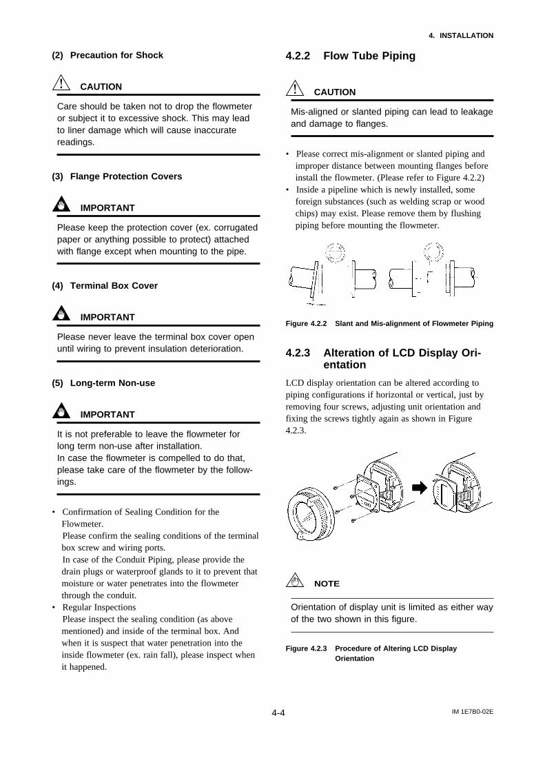
4.2.2 Flow Tube Piping
CAUTION
Mis-aligned or slanted piping can lead to leakageand damage to flanges.
• Please correct mis-alignment or slanted piping andimproper distance between mounting flanges beforeinstall the flowmeter. (Please refer to Figure 4.2.2)
• Inside a pipeline which is newly installed, someforeign substances (such as welding scrap or woodchips) may exist. Please remove them by flushingpiping before mounting the flowmeter.
Figure 4.2.2 Slant and Mis-alignment of Flowmeter Piping
4.2.3 Alteration of LCD Display Ori-entation
LCD display orientation can be altered according topiping configurations if horizontal or vertical, just byremoving four screws, adjusting unit orientation andfixing the screws tightly again as shown in Figure4.2.3.
NOTE
Orientation of display unit is limited as either wayof the two shown in this figure.
Figure 4.2.3 Procedure of Altering LCD DisplayOrientation

IM 1E7B0-02E4-5
4. INSTALLATION
4.3 Mounting
4.3.1 Nominal Diameter 2.5 mm(0.1in.) to 10 mm (0.4in.) UnionJoint Type
NOTE
Please ensure to use the attached connectingfittings.
Ceramic linings with a diameter of 2.5, 5 or 10 mm areconnected using union joints.
Use the connecting fittings according to the tablebelow. Depending on whether the fitting is to bewelded to or screwed on to the piping.
Table 4.3.1 Fitting Dimensions
D
ØA
ØA
ØB
ØB
ØC
4(0.16)
11.5(0.4)
Screw joint (Code: U2, U3)
Weld joint (Code: U1)
30(1.2)
4(0.16) 35(1.38)
10(0.39)
0–0.1
ØC0.30 ØD
0–0.1
Sizemm(inch) Code A B C D
2.5(0.1)
5(0.2)
10(0.4)
U2
U3
U2
U3
U2
U3
22(0.87)
22(0.87)
22(0.87)
22(0.87)
25(0.98)
25(0.98)
8(0.31)
8(0.31)
8(0.31)
8(0.31)
10(0.39)
10(0.39)
18.5(0.73)
18.5(0.73)
18.5(0.73)
18.5(0.73)
22.5(0.89)
22.5(0.89)
R1/4(PT1/4)
NPT1/4
R1/4(PT1/4)
NPT1/4
R3/8(PT3/8)
NPT3/8
Sizemm(inch) Code A B C D
2.5(0.1)
5(0.2)
10(0.4)
U1
U1
U1
22(0.87)
22(0.87)
25(0.98)
8(0.31)
8(0.31)
10(0.39)
14.3(0.56)
14.3(0.56)
17.8(0.70)
18.5(0.73)
18.5(0.73)
22.5(0.89)
T040301.EPS
Unit: mm (inch)
(1) Mounting DirectionPlease mount the Magnetic Flowmeter matching theflow direction of the fluid to be measured with thedirection of the arrow mark on the flowmeter.
IMPORTANT
If it is impossible to match the direction, pleasenever remodel by changing direction of theconverter. In case the measuring fluid flowsagainst the arrow direction, please refer to thesection 6.3.6 or 7.2.8 Reversing Flow Direction.
(2) Connecting Process PipingWeld or screw the connecting fittings to the processpiping.
IMPORTANT
• Please be sure to pass the connecting fittingsthrough the union joint nuts in advance. Thenconnect the connecting fitting to the piping byscrewing or welding the connecting fitting to thepiping (see Figure 4.3.1).
• In case of weld joint type, please pay attentionthe welding condition to avoid deforming pipingor making the stagnant portion of the fluid;joint preparation, level defference in butt joint,welding current.
(3) Positioning FlowmeterInstall the magnetic flowmeter on a mounting base andposition it so that the center axis of the flowmeter isaligned with that of the piping. Then mount theflowmeter to union joint nuts by screwing the nuts tothe connecting ports of the flowmeter.
CAUTION
The ceramic pipe will be damaged if they aretightened when they are not properly aligned.
(4) Tightening Nuts
CAUTION
Tighten the union joint nuts according to TorqueValues in Table 4.3.2 using a torque wrench. Asthe gasket material is Fluorocarbon PTFE, it ispossible that nuts may loose by it’s character astime passes. Please tighten the nuts regularly.The table below shows the tightening torquevalues. Be sure to use gasket : t=1.5 attached.

IM 1E7B0-02E4-6
4. INSTALLATION
GasketConnecting fitting
Union joint nut
Pipe*
* User’s scope
Mounting base*
Horizontal Mounting
Vertical Mounting
Figure 4.3.1 Mounting Procedure (Size: 2.5 mm(0.1in.) to10 mm(0.4in.))
Table 4.3.2 Tightening Torque
Size: mm(inch) Tightening Torque N-m kgf-cm [in-lbf]
2.5(0.1)
5(0.2)
10(0.4)
Max.12122[106]
Max.12122[106]
Max.18183[160]
T040302.EPS
4.3.2 Nominal Diameter 2.5mm(0.1in.) to 40mm (1.5in.) WaferType
IMPORTANT
Please use appropriate bolts and nuts accordingto process connection. In case stud type ofthrough bolts are used, be sure outside diameterof a shank is smaller than a thread ridge’s one.Please use compressed non-asbestos fibergasket, PTFE gasket or the gasket which hasequal elasticity. In case of optional code/FRG,please use rubber gasket or others which hasequal elasticity. Be sure the inner diameter ofthe gasket does not protrude to inner piping.(Refer to Table 4.3.8)
(1) Mounting DirectionPlease mount the Magnetic Flowmeter matching theflow direction of the fluid to be measured with thedirection of the arrow mark on the flowmeter.
IMPORTANT
If it is impossible to match the direction, pleasenever remodel by changing direction of theconverter. In case the measuring fluid flowsagainst the arrow direction, please refer to thesection 6.3.6 or 7.2.8 Reversing Flow Direction.
(2) Mounting Centering DevicesTo keep concentricity of the Flowmeter with pipes,please mount centering devices on the Mini-Flanges ofthe Flowmeter.
Please give attention to the nominal diameter andflange ratings of the centering devices.
(3) Positioning FlowmeterPlease pass two through-bolts to adjacent holes of bothflanges and mount the Flowmeter, and pass otherthrough-bolts to other holes. (Refer to Figure 4.3.2/4.3.3) In case stud type of through-bolts are used,position them coming in contact centering devices withthread of bolts.
(4) Tightening NutsPlease tighten the bolts according to Torque Values inTable 4.3.3. In case of PVC piping, please selectoptional code /FRG, use rubber gasket and tighten withthe torque value in Table 4.3.4.

IM 1E7B0-02E4-7
4. INSTALLATION
CAUTION
In case of PFA lining type, as the lining materialis Fluorocarbon PFA, it is possible that nuts mayloose by its character as time passes. Pleasetighten the nuts regularly.Please be sure to tighten the bolts followingprescribed torque values. Please tighten theflange bolts diagonally with the same torquevalues, step by step up to the prescribed torquevalue.
Through bolts (four)
Flange
Mini-flangeCentering devices (two)
Gaskets (two)
Nuts (eight)
Horizontal Mounting Vertical Mounting
Please use appropriate bolts and nuts according to process connection.
Figure 4.3.2 Mounting Procedure (Size: 2.5 mm(0.1in.) to 15 mm(0.5in.))
Through bolts (four)
Flange
Mini-flange
Centering devices (two)
Gaskets (two)
Nuts (eight)
Horizontal Mounting Vertical Mounting
Please use appropriate bolts and nuts according to process connection.
Figure 4.3.3 Mounting Procedure (Size: 25 mm(1in.), 40 mm(1.5in.))

IM 1E7B0-02E4-8
4. INSTALLATION
Table 4.3.3 Wafer Type Tightening Torque Values for Metal Piping
FlangeRatingSize
mm(inch)
2.5(0.1), 5(0.2)10(0.4), 15(0.5)
25(1)
40(1.5)
JIS ANSI DIN
10K 20K 150 300 PN10/16/40
6 to 961 to 92[53 to 80]
15 to 22153 to 224[133 to 195]
21 to 32214 to 327[186 to 283]
Tightening Torque Values for PFA lining / Polyurethane lining Type N-m kgf-cm [in-lbf]
6 to 961 to 92[53 to 80]
15 to 22153 to 224[133 to 195]
21 to 32214 to 327[186 to 283]
6 to 961 to 92[53 to 80]
12 to 18122 to 184[106 to 159]
17 to 26173 to 265[150 to 230]
6 to 961 to 92[53 to 80]
15 to 22153 to 224[133 to 195]
25 to 38255 to 388[221 to 336]
6 to 862 to 86[54 to 75]
13 to 17129 to 169[112 to 147]
23 to 31239 to 319[208 to 277]
Maximum Tightening Torque Values for Ceramic lining Type N-m kgf-cm [in-lbf]
FlangeRatingSize
mm(inch)
15(0.5)
JIS
10K 20K14
143[124]
25(1)30
306[265]
40(1.5)44
449[389]
14143[124]
14143[124]
30306[265]
22224[195]
44449[389]
150 300
DINANSI
PN10/16/40
33337[292]
14143[124]
51520[451]
30306[265]
11110[96]
25250[217]
50500[435]
*Please use compressed non-asbestos fiber gasket, PTFE gasket or the gasket which has equal elasticity.T040303.EPS
Table 4.3.4 Wafer Type Tightening Torque Values for PVC Piping
FlangeRatingSize
mm(inch)
2.5(0.1), 5(0.2)10(0.4), 15(0.5)
25(1)
40(1.5)
JIS ANSI DIN
10K 20K 150 300 PN10/16/40
2.020[18]
Tightening Torque Values for PFA lining / Polyurethane lining Type N-m kgf-cm [in-lbf]
Maximum Tightening Torque Values for Ceramic Type N-m kgf-cm [in-lbf]
FlangeRatingSize
mm(inch)
15(0.5)
JIS
10K 20K
1.313[12]
25(1)3.536[31]
40(1.5)5.758[50]
2.829[25]
150 300
ANSI
4.647[41]
2.121[19]
—
5.253[46]
7.476[65]
—
—
4.243[37]
6.061[53]
—
—
—
1.818[16]
3.637[32]
6.768[59]
—
—
—
1.313[12]
2.829[25]
—
—
—
DIN
PN10/16/40
1.313[12]
6.162[54]
*Please select optional code/FRG and use rubber gasket or others which has equal elasticity.T040304.EPS

IM 1E7B0-02E4-9
4. INSTALLATION
4.3.3 Nominal Diameter 50 mm(2in.)to 300 mm(12in.) Wafer Type
IMPORTANT
Please use appropriate bolts and nuts accordingto process connection. In case stud type ofthrough bolts are used, be sure outside diameterof a shank is smaller than a thread ridge’s one.Please use compressed non-asbestos fibergasket, PTFE gasket or the gasket which hasequal elasticity. In case of optional code/FRG,please use rubber gasket or others which hasequal elasticity. Be sure the inner diameter ofthe gasket does not protrude to inner piping.(Refer to Table 4.3.8)
(1) Mounting DirectionPlease mount the Magnetic Flowmeter matching theflow direction of the fluid to be measured with thedirection of the arrow mark on the flowmeter.
IMPORTANT
If it is impossible to match the direction, pleasenever remodel to change direction of the con-verter. In case the measuring fluid flows againstthe arrow direction, please refer to the section6.3.6 or 7.2.8 Reversing Flow Direction.
(2) Mounting Centering DevicesTo keep concentricity between the Flowmeter andpipes, centering devices must be used. Pass twothrough-bolts through the four centering devices (twofor each) and lower adjacent holes of both flanges.(Refer to Figure 4.3.4)
Please give attention to the nominal size and flangeratings of the centering devices. (Refer to Table 4.3.7)
(3) Positioning FlowmeterPosition the Flowmeter coming in contact four center-ing devices with Mini-Flanges. At this time, payattention to avoid four centering devices come incontact with Housing. In case stud type of through-bolts are used, position them coming in contact fourcentering devices with thread of the bolts. (Refer toFigure 4.3.4) After positioning the Flowmeter, passremaining through-bolts to remaining holes.
NOTE
When installing a size 150mm with JIS F12(JIS75M) flange, please displace in circumferen-tial direction slightly because the cover ofelectrode chamber will interfere against the bolts.
(4) Tightening NutsPlease tighten the bolts according to Torque Values inTable 4.3.5. In case of PVC piping, please selectoptional code/FRG, use rubber gasket and tighten withthe torque value in Table 4.3.6.
CAUTION
In case of PFA lining type as the lining materialis Fluorocarbon PFA, it is possible that nutsloose by its character as time passes. Pleasetighten the nuts regularly.Please be sure to tighten the bolts followingprescribed torque values. Please tighten theflange bolts diagonally with the same torquevalues, step by step up to the prescribed torquevalue.
Nuts
FlangeGaskets(two)
Mini-flange
Housing
Through bolts
Centering devices(four)Please use appropriate bolts and nuts according to process connection.
Horizontal Mounting Vertical Mounting
Figure 4.3.4 Mounting Procedure

IM 1E7B0-02E4-10
4. INSTALLATION
Table 4.3.5 Wafer Type Tightening Torque Values for Metal Piping
FlangeRatingSize
mm(inch)
100(4)
50(2)
80(3)
JIS ANSI DIN
10K 20K 150 300 PN10
35 to 51357 to 520[310 to 451]
65 to 94663 to 959[575 to 832]
57 to 84582 to 857[504 to 743]
Tightening Torque Values for PFA lining / Polyurethane lining Type N-m kgf-cm [in-lbf]
43 to 64439 to 653[381 to 566]
43 to 68439 to 694[381 to 602]
61 to 92622 to 939[540 to 814]
35 to 51357 to 520[310 to 451]
63 to 89643 to 908[558 to 788]
93 to 120949 to 1224[823 to 1062]
41 to 61418 to 622[363 to 540]
41 to 60418 to 612[363 to 531]
65 to 93663 to 949[575 to 823]
65 to 94663 to 959[575 to 832]
94 to 125959 to 1276[832 to 1106]
Maximum Tightening Torque Values for Ceramic lining Type N-m kgf-cm [in-lbf]
FlangeRatingSize
mm(inch)
50(2)
JIS
10K 20K
50510[442]
80(3)36
367[319]
100(4)48
490[425]
27276[239]
50510[442]
44449[389]
75765[664]
58592[513]
150 300
DIN PNANSI
49500[434]
27276[239]
56571[496]
44449[389]
150(6)
200(8)
28 to 42286 to 429[248 to 372]
21 to 31214 to 316[186 to 274]
14 to 21143 to 214[124 to 186]
26 to 39265 to 398[230 to 345]
41 to 61418 to 622[363 to 540]
28 to 42286 to 429[248 to 372]
14 to 21143 to 214[124 to 186]
25 to 37255 to 378[221 to 327]
PN16JIS G3451
F12
65(2.5)52 to 60
530 to 610[460 to 531]
52 to 60530 to 610[460 to 531]
52 to 60530 to 610[460 to 531]
125(5)62 to 75
630 to 760[549 to 664]
60 to 72610 to 730[531 to 637]
52 to 60530 to 610[460 to 531]
21 to 31214 to 316[186 to 274]
35 to 52357 to 531[310 to 460]
65 to 94663 to 959[575 to 832]
58 to 84592 to 857[513 to 743]
41 to 62418 to 633[363 to 549]
71 to 80720 to 810[628 to 708]
68 to 102694 to 1041[602 to 903]
68 to 100694 to 1020[602 to 885]
69 to 101704 to 1031[611 to 894]
98 to 128996 to 1307[867 to 1133]
85 to 108871 to 1098[752 to 956]
89 to 130909 to 1329[788 to 1150]
106 to 1461083 to 1489[938 to 1292]
91 to 117924 to 1195[805 to 1035]
108 to 1311103 to 1339[956 to 1159]
250(10)
300(12)
139 to 1761416 to 1792[1230 to 1558]
131 to 1581337 to 1606[1159 to 1398]
63643[558]
63643[558]
36367[319]
48490[425]
84857[743]
80816[708]
1051071[929]
PN10 PN16 PN40JIS G3451
F12
150(6) —
200(8)
1101126[979]
97986[857]
78799[695]
1051069[930]
92943[820]
1341372[1193]
61618[537]
1011028[894]
1431460[1270]
1071093[950]
94957[832]
1021041[903]
*Please use compressed non-asbestos fiber gasket, PTFE gasket or the gasket which has equal elasticity.
— —
—
—
—
—
—
—
—
—
—
—
—
—
—
—
—
—
PN40
32 to 41327 to 419[284 to 364]
32 to 41327 to 419[284 to 364]
—
—
—
—
—
—
——
—
—
—
—
—
—
—
T040305.EPS
Table 4.3.6 Wafer Type Tightening Torque Values for PVC Piping
FlangeRatingSize
mm(inch)
50(2) — — —
— — —
— — —
— —
— —
— —
— —
— —
—
— — —
—
—
—
—
—
— — — —
—
—
—
—
150(6)
200(8)
JIS ANSI DIN
10K 20K 150 300 PN10
9.8100[87]
Tightening Torque Values for PFA lining / Polyurethane lining Type N-m kgf-cm [in-lbf]
Maximum Tightening Torque Values for Ceramic lining Type N-m kgf-cm [in-lbf]
FlangeRatingSize
mm(inch)
JIS
10K 20K
8.284[73]
6.263[55]
8.082[71]
150 300
ANSI
8.183[72]
21.4218[189]
19.3197[171]
20.5209[181]
27.6282[244]
21.4218[189]
28.9295[256]
8.284[73]
12.4127[110]
DIN
80(3)
100(4)
7.273[64]
12.2124[108]
14.4147[127]
12.2124[108]
9.8100[87]
PN16JIS G3451F12(75M)
12.2124[108]
9.193[81]
9.193[81]
23.4239[207]
31.6322[280]
14.4147[127]
24.4249[216]
19.3197[171]
7.273[64]
21.4218[189]
PN10 PN16
PN40
PN40JIS G3451F12(75M)
50(2)
150(6)
200(8)
80(3)
100(4)
19.8202[175]
17.5179[155]
18.9193[167]
25.1256[222]
26.2267[232]
19.8202[175]
8.991[79]
8.991[79]
6.263[55]
8.082[71]
19.8202[175]
17.5179[155]
12.3126[109]
16.1164[142]
21.6220[191]
28.7293[254]
*Please select optional code/FRG and use rubber gasket or others which has equal elasticity.T040306.EPS
IM 1E7B0-02E4-11
4. INSTALLATION
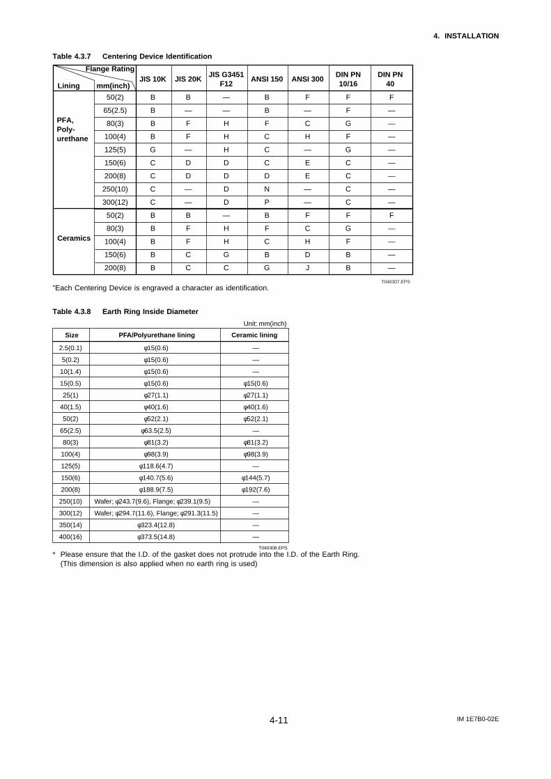
Table 4.3.7 Centering Device Identification
JIS 10K
50(2)
65(2.5)
80(3)
100(4)
125(5)
150(6)
200(8)
250(10)
300(12)
50(2)
80(3)
100(4)
150(6)
200(8)
B
B
B
B
G
C
C
C
C
B
B
B
B
B
B
—
F
F
—
D
D
—
—
B
F
F
C
C
—
—
H
H
H
D
D
D
D
—
H
H
G
C
B
B
F
C
C
C
D
N
P
B
F
C
B
G
F
—
C
H
—
E
E
—
—
F
C
H
D
J
F
—
—
—
—
—
—
—
—
F
—
—
—
—
F
F
G
F
G
C
C
C
C
F
G
F
B
B
JIS 20KJIS G3451
F12ANSI 150 ANSI 300
DIN PN10/16
DIN PN40
PFA,Poly-urethane
Ceramics
Lining mm(inch)
Flange Rating
T040307.EPS
"Each Centering Device is engraved a character as identification.
Table 4.3.8 Earth Ring Inside Diameter
Size PFA/Polyurethane lining Ceramic lining
2.5(0.1)
5(0.2)
10(1.4)
15(0.5)
25(1)
40(1.5)
50(2)
65(2.5)
80(3)
100(4)
125(5)
150(6)
200(8)
250(10)
300(12)
350(14)
400(16)
φ15(0.6)
φ15(0.6)
φ15(0.6)
φ15(0.6)
φ27(1.1)
φ40(1.6)
φ52(2.1)
φ63.5(2.5)
φ81(3.2)
φ98(3.9)
φ118.6(4.7)
φ140.7(5.6)
φ188.9(7.5)
Wafer; φ243.7(9.6), Flange; φ239.1(9.5)
Wafer; φ294.7(11.6), Flange; φ291.3(11.5)
φ323.4(12.8)
φ373.5(14.8)
—
—
—
φ15(0.6)
φ27(1.1)
φ40(1.6)
φ52(2.1)
—
φ81(3.2)
φ98(3.9)
—
φ144(5.7)
φ192(7.6)
—
—
—
—
T040308.EPS
Unit: mm(inch)
* Please ensure that the I.D. of the gasket does not protrude into the I.D. of the Earth Ring.(This dimension is also applied when no earth ring is used)

IM 1E7B0-02E4-12
4. INSTALLATION
4.3.4 Nominal Diameter 15 mm(0.5in.) to 400 mm (16in.) FlangeType
IMPORTANT
Please use appropriate bolts and nuts accordingto process connection. Please use compressednon-asbestos fiber gasket, PTFE gasket or thegasket which has equal elasticity. In case ofoptional code/FRG, please use rubber gasket orothers which has equal elasticity. Be sure theinner diameter of the gasket does not protrude toinner piping.(Refer to Table 4.3.8)
(1) Mounting DirectionPlease mount the Magnetic Flowmeter matching theflow direction of the fluid to be measured with thedirection of the arrow mark on the flowmeter.
IMPORTANT
If it is impossible to match the direction, pleasenever remodel to change direction of the con-verter. In case the measuring fluid flows againstthe arrow direction, please refer to the section6.3.6 or 7.2.8 Reversing Flow Direction.
(2) Tightening NutsPlease tighten the bolts according to Torque Values inTable 4.3.9. In case of PVC piping, please selectoptional code/FRG, use rubber gasket and tighten withthe torque value in Table 4.3.10.
CAUTION
In case of PFA lining type as the lining materialis Fluorocarbon PFA, it is possible that boltsloose by its character as time passes. Pleasetighten the nuts regularly.Please be sure to tighten the bolts followingprescribed torque values. Please tighten theflange bolts diagonally with the same torquevalues, step by step up to the prescribed torquevalue.
Flanges(Flowmeter side)
Gaskets(two)
Flanges(Pipe side)
Bolts
Nuts
Please use appropriate bolts and nuts according to process connection.
Figure 4.3.5 Mounting Procedure (Size: 15 mm (0.5in.) to 400 mm (16in.))

IM 1E7B0-02E4-13
4. INSTALLATION
Table 4.3.9 Flange Type Tightening Torque Values for Metal Piping in N-mkgf-cm [in-lbf]
FlangeRatingSize
mm(inch)
40(1.5)
15(0.5)
25(1)
JIS ANSI DIN
10K 20K 150 300 PN10
18 to 26184 to 265[159 to 230]
22 to 31224 to 316[195 to 274]
15 to 22153 to 224[133 to 195]
11 to16112 to 163[97 to 142]
18 to 27184 to 276[159 to 239]
15 to 21153 to 214[133 to 186]
23 to 31235 to 316[204 to 274]
35 to 43357 to 439[310 to 381]
21 to 31214 to 316[186 to 274]
11 to 16112 to 163[97 to 142]
100(4)
50(2)
80(3)
3 to 531 to 51[27 to 44]
8 to 1382 to 133[71 to 115]
6 to 1061 to 102[53 to 88]
PN16JIS G3451F12(75M)
16 to 22163 to 224[142 to 195]
33 to 47337 to 480[292 to 416]
150(6)
200(8)
250(10)
300(12)
350(14)
400(16)
57 to 84582 to 857[504 to 743]
142 to 1741449 to 1776[1257 to 1540]
114 to 1381163 to 1408[1009 to 1221]
21 to 35214 to 357[186 to 310]
65 to 94663 to 959[575 to 832]
158 to 1831612 to 1867[1398 to 1619]
243 to 2612480 to 2663[2150 to 2310]
61 to 92622 to 939[540 to 814]
154 to 1821571 to 1857[1363 to 1611]
125 to 1451276 to 1480[1106 to 1283]
25 to 44255 to 449[221 to 389]
43 to 68439 to 694[381 to 602]
93 to 120949 to 1224[823 to 1062]
145 to 1771480 to 1806[1283 to 1566]
164 to 1871673 to 1908[1451 to 1655]
22 to 35224 to 357[195 to 310]
63 to 89643 to 908[558 to 788]
245 to 2842500 to 2898[2168 to 2513]
253 to 2752582 to 2806[2239 to 2434]
65 to 93663 to 949[575 to 823]
126 to 1511286 to 1541[1115 to 1336]
154 to 1801571 to 1837[1363 to 1593]
25 to 42255 to 429[221 to 372]
41 to 59418 to 602[363 to 522]
94 to 125959 to 1276[832 to 1106]
136 to 1641388 to 1673[1204 to 1451]
155 to 1991582 to 2031[1372 to 1761]
65 to 94663 to 959[575 to 832]
152 to 1921551 to 1959[1345 to 1699]
248 to 3312531 to 3378[2195 to 2929]
69 to 101704 to 1031[611 to 894]
215 to 2702194 to 2755[1903 to 2389]
190 to 2491939 to 2541[1681 to 2204]
47 to 75480 to 765[416 to 664]
65 to 100663 to 1020[575 to 885]
274 to 3252796 to 3316[2425 to 2876]
313 to 3953194 to 4031[2770 to 3496]
58 to 84592 to 857[513 to 743]
154 to 1751571 to 1786[1363 to 1549]
175 to 2131786 to 2173[1549 to 1885]
21 to 35214 to 357[186 to 310]
65 to 94663 to 959[575 to 832]
3 to 531 to 51[27 to 44]
8 to 1382 to 133[71 to 115]
18 to 26184 to 265[159 to 230]
3 to 531 to 51[27 to 44]
3 to 531 to 51[27 to 44]
6 to 862 to 89[54 to 77]
8 to 1382 to 133[71 to 115]
18 to 26184 to 265[159 to 230]
12 to 17124 to 169[108 to 147]
22 to 31226 to 319[197 to 277]
30 to 41308 to 419[268 to 364]
12 to 17124 to 169[108 to 147]
22 to 31226 to 319[197 to 277]
30 to 41308 to 419[268 to 364]
T040309.EPS*Please use compressed non-asbestos fiber gasket, PTFE gasket or the gasket which has equal elasticity.
—
—
—
—
—
—
—
—
—
—
—
—
PN40
6 to 862 to 89[54 to 77]
—
—
—
—
—
—
—
—
—
—
—
—
Table 4.3.10 Flange Type Tightening Torque Values for PVC Piping in N-mkgf-cm [in-lbf]
FlangeRatingSize
mm(inch)
JIS
10K 20K
1.111[10]2.930[26]5.960[52]
150 300
ANSI
4.748[42]
2.323[20]
PN10 PN16 PN40JIS G3451F12(75M)
15(0.5)
50(2)
80(3)
25(1)
40(1.5)
7.273[64]4.950[43]
9.9101[88]
39.44,2[349]
8.183[72]
3.536[31]6.465[56]
8.788[76]
3.536[31]6.465[56]
8.788[76]
4.950[43]
9.9101[88]
16.3166[144]
32.633[288]43.1440[381]
*Please select optional code/FRG and use rubber gasket or others which has equal elasticity.
100(4)
150(6)
200(8)
8.183[72]29.8304[264]
26.3268[233]
8.284[73]28.5291[252]
37.7385[334]
1.111[10]
7.273[64]
29.8304[264]
29.8304[264]
26.3268[233]
1.717[15]
1.717[15]
—
—
—
—
—
—
—
—
—
—
—
—
—
—
—
—
—
—
—
—
—
—
—
—
—
—
—
—
—
—
DIN
T040310.EPS

IM 1E7B0-02E4-14
4. INSTALLATION
4.3.5 Mounting Procedure for Sani-tary Type
The sanitary type is mounted using ISO(IDF) clamps.
(1) Mounting DirectionPlease mount the Magnetic Flowmeter matching theflow direction of the fluid to be measured with thedirection of the arrow mark on the flowmeter.
IMPORTANT
If it is impossible to macth the direction, pleasenever remodel to change direction of the termi-nal box. In case the measuring fluid flowsagainst the arrow direction, please refer to thesection 6.3.6 or 7.2.8 Reversing Flow Direction.
(2) Welding of Mating Ferrule to Piping
IMPORTANT
Weld the attached ferrules to the piping. Pleasepay attention to the welding condition to avoiddeforming piping or making the stagnant portionof the fluid; joint preparation, level difference inbutt joint, welding current.
(3) Mounting GasketMount the attached gasket so it fits into the groove onthe ferrule.
(4) Positioning FlowmeterPosition the flowmeter between the mating ferrule.
(5) Tightening ClampMount the clamp so they cover the flowmeter andmating ferrule tapered part.
Clamp
GasketFerrule
Welding
Pipe
Figure 4.3.8 Mounting Procedure
4.4 Wiring Precautions
CAUTION
Please confirm that all conncetions are correctbefore applying power to the instrument.Improper wiring may damage the flowmeter.
The external signal wirings are connected into theterminal inside the converter. Please connect to eachterminal (Please refer to Figure 4.4.1) by taking off acover backside the converter.
Terminal Symbols Description
N– L+I +I –P+P–
Protective grounding Power Supply
Current Output 4 to 20mA DC
Pulse, alarm or status output
Power supplyProtective grounding4 to 20 mA DC outputPulse, alarm or status output
Figure 4.4.1 Terminal
4.4.1 Protective Grounding
CAUTION
Please be sure to connect protective groundingof ADMAG AE with cable of 2mm2 or largercross section in order to avoid the electricalshock to the operators and maintenance engi-neers and prevent the influence of externalnoise. And further connect the grounding wire tothe mark (100Ω or less).

IM 1E7B0-02E4-15
4. INSTALLATION
4.4.2 General PrecautionsPlease give attention to the followings in wiring.
CAUTION
• Please pay attention to avoid the cable isbended excessively.
• In case the ambient temperature exceeds50˚C(122˚F), please use heat-resistant cableswith maximum allowable temperature of70˚C(158˚F) or above for TIIS(JIS) flameprooftype.
• Please do not connect cables outdoors in caseof rain to prevent damages from dew formationand to keep insulation inside the terminal boxof the flowmeter.
• The all cable ends are to be provided withround crimp-on terminal.
• The power cables and signal cables must berouted in separate steel conduit tubes orflexible tubes.(except 4-core 24VDC cablewiring.)
• When waterproof glands, union equippedwaterproof glands are used, the glands must beproperly tightened to keep the box watertight.
• Please install a external switch or circuitbreaker as a means of power off (capacitance;15A, conform to IEC947-1 and IEC947-3). Thepreferable location is either near the instrumentor other places to easy operation. Further-more, please indicate "power off equipment" onthe those external switch or circuit breaker.
• Please be sure to fully tighten the terminal boxcover before the power is turned on.
• Please be sure to turn off the power beforeopening the terminal box cover.
• In case of DC power supply, a plug is attached.When 4-core cable is used, please put thatplug into unused electrical connection port.
4.4.3 Power and Output CablesPower cable: •Crimp-on Terminal •Green/Yellow covered conductors shall be used only for connection to PROTECTIVE CONDUCTOR TERMINALS. •Conform to IEC227, IEC245 or equivalent national authorization.Output cable: •Please use Polyvinyl chloride insulated and sheathed control cables (JIS C3401) or Polyvinyl chloride insulated and sheathed portable power cables (JIS C3312) or equivalents.Outer diameter: •6.5 to 12mm in diameter (10.5 or 11.5mm for /ECG, /ECU; 8.5 to 11mm for /G11, /G12)Nominal crosss section: •Single wire; 0.5 to 2.5mm2 , Stranded wire; 0.5 to
2.5mm2
4.4.4 DC Connections
(1)Connecting Power Supply
IMPORTANT
In case of 24VDC power supply, AC powersupplies or reversed polarities cannot be con-nected. It will cause the fuse to burn out.
(2)Supplied Voltage Rating
IMPORTANT
In case of 24VDC power supply, the specifica-tion for the supply voltage is 24VDC (-15 to+20%), but the input voltage of the converterdrops due to cable resistance so it should beused within the following range.
1000
900
800
700
600
500
400
300
200
100
020 22 24 26 28
Usable range E(V)
Supply Voltage and Cable Length
Allowedcablelengthm(ft)
(3300)
(2970)
(2640)
(2310)
(1980)
(1650)
(1320)
(990)
(660)
(330)
Cable cross section area : 1.25mm2 Cable cross section area : 2mm2
(3)Setting Power Supply Frequency
IMPORTANT
In case of 24VDC power supply, the frequencyof the power supply has to be adjusted. Pleaseadjust for the local power frequency. The powersupply frequency is set in parameter B12 (orPower freq for HART). Refer to 6.2 or 7.5.2 fordata setting procedure.
4.4.5 Wiring PortsPlease select the most suitable standard of wiringprocedure for the wiring ports by customer’s own.
(1)Using the Waterproof Gland
IMPORTANT
To prevent water or condensate from enteringthe converter housing, waterproof glands arerecommended. Do not over-tighten the glands ordamage to the cables may result. Tightness ofthe gland can be checked by confirming that thecable is held firmly in place.
IM 1E7B0-02E4-16
4. INSTALLATION
Waterproof glandOptional specification code : /ECG
Waterproof gland with union jointOptional specification code : /ECU
Gasket
Gasket
Tightening gland
Tightening gland
G 1/2
G 1/2
Washer
Figure 4.4.2 Waterproof Gland
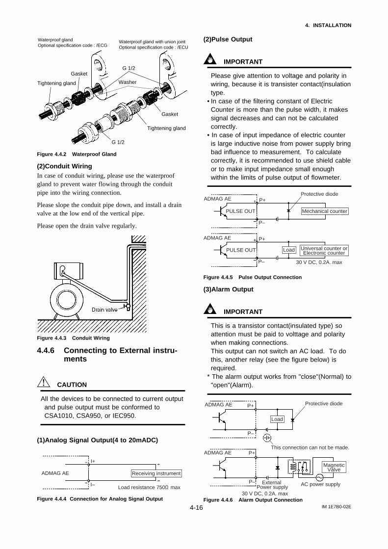
(2)Conduit WiringIn case of conduit wiring, please use the waterproofgland to prevent water flowing through the conduitpipe into the wiring connection.
Please slope the conduit pipe down, and install a drainvalve at the low end of the vertical pipe.
Please open the drain valve regularly.
Figure 4.4.3 Conduit Wiring
4.4.6 Connecting to External instru-ments
CAUTION
All the devices to be connected to current outputand pulse output must be conformed toCSA1010, CSA950, or IEC950.
(1)Analog Signal Output(4 to 20mADC)
ADMAG AE
I+
I– Load resistance 750Ω max
Receiving instrument
Figure 4.4.4 Connection for Analog Signal Output
(2)Pulse Output
IMPORTANT
Please give attention to voltage and polarity inwiring, because it is transister contact(insulationtype.
• In case of the filtering constant of ElectricCounter is more than the pulse width, it makessignal decreases and can not be calculatedcorrectly.
• In case of input impedance of electric counteris large inductive noise from power supply bringbad influence to measurement. To calculatecorrectly, it is recommended to use shield cableor to make input impedance small enoughwithin the limits of pulse output of flowmeter.
ADMAG AE P+
P–
Protective diode
ADMAG AE
Universal counter orElectronic counter
Load
PULSE OUT
PULSE OUT
30 V DC, 0.2A. max
Mechanical counter
P+
P–
Figure 4.4.5 Pulse Output Connection
(3)Alarm Output
IMPORTANT
This is a transistor contact(insulated type) soattention must be paid to volttage and polaritywhen making connections.This output can not switch an AC load. To dothis, another relay (see the figure below) isrequired.
* The alarm output works from "close"(Normal) to"open"(Alarm).
ADMAG AE
P+
P–
Protective diodeADMAG AE
MagneticValve
Load
30 V DC, 0.2A. max
P+
P– External Power supply AC power supply
This connection can not be made.
Figure 4.4.6 Alarm Output Connection

5. BASIC OPERATING PROCEDURES
IM 1E7B0-02E5-1
5. BASIC OPERATING PROCEDURES
All data settings can be performed with the three keys on the front panel (SET, SHIFT andINC) or using a handheld BRAIN (BT) terminal.
The following sections describe basic data configurations and how to use the three panelkeys. (See chapter 7 for information on BT operations.)
5.1 Liquid Crystal DisplayFigure 5.1 shows the configuration of the ADMAG AE display panel (if equipped).
%l gal m3 /h /m
SET SHIFT INC
(The figure shows display when fully lit)(1) LED (red)Normal operation : off
(2) Delimiter
(3) Unit DisplayUnits displayed:l : litergal : gallonm3: cubic meters/h: hours/m: minutesIf other units are to be used, attach labels giving the specific unit. (7) Setting Keys
(6) Decimal Points
(5) Data Display
(4) Unit Label Location
Figure5.1 Configuration of Display
(1) LED (red) : This LED is off during normal operation and flasheswhen an alarm condition has occurred.
(2) Delimiter : The delimiter " : " (colon) indicates that the displayed data isin setting mode.
(3) Unit Display : Displays flow rate units. In order to display other units, therequired unit label should be selected from the provided datasheets and attached as shown.
(4) Unit Label Location : To display units not on the LCD, select the required labelfrom the provided data sheets and attach it here.
(5) Data Display : Displays flow rate data, setting data and type of alarmgenerated.
(6) Decimal Point : Displays decimal point in the data(7) Setting Keys : These keys are used to change flow rate data displays and
type of setting data.

5. BASIC OPERATING PROCEDURES
IM 1E7B0-02E5-2
5.2 Types of Display DataThree major types of data are displayed.
This mode displays flowrates and totalization date.Go to the setting modeand use parameter "d1" tochange display items.This mode can be called up by pressing "SET" key while pressing "SHIFT" key when setting mode is displayed.
1. Flow Rate Data Display Mode
Display Example)
%
(Flow rate %)
(Actual flow rate)
m3 /h
(Flow rate totalization value)
(Alternate display offlow rate % and flowrate totalization value)
(Alternate display ofactual flow rate and flowrate totalization value)
(Alternate display ofactual flow rate and flow rate %)
2. Setting Mode
Display Example)
(Data item 02: 3 sec.dumping)
(Data item 03: Span 50.0)
(Data item C1: Zero adjust not possible)
(Data item d1: Selection of display items)
(Data item E1: Selection of totalization units)
3. Alarm Display Mode
Display Example)
(Error 07: Coil open)
(Error 06: Input signal error)
(Error 08: Incorrect span setting)
(Error 20: Metering tube notfilled with water)
This mode is used to checkparameter content and rewrite data. This modecan be called up from theflow rate data display mode bypressing the "SET" key.
When an alarm situation occurs, this mode will replace the current mode(flow rate or setting mode)to show what type ofalarm has occurred.

5. BASIC OPERATING PROCEDURES
IM 1E7B0-02E5-3
5.2.1 Flow Rate Data Display Mode
• The flow rate data display mode indicates instantaneous flow and totalized flowvalues.The ADMAG AE can display 12 types of flow rate data.
• This function can be set in the parameter "d1" of the flow converter.• For changing from setting mode to flow rate data display mode, press "SET" key
while pressing "SHIFT" key.• When a BT is used, call up the "D01 DISP SELECT" parameter to select functions.
Display item Content ADMAG AE Setting BT Setting
Forward Flow Rate %
Instantaneous flow rate is displayed within a range of -8(or -108) to 108 for the span.
Actual forward Flow Rate
The actual meter rate of instantaneous flow rate is displayed.(See note 1.)The decimal place is the same as for the span
setting. However,since a decimal point set at the
most sifnigficant bit cannot be displayed.
It is automatically shifted 1 digit to the right. (BT setting
of 0.0001 is displayed as 0.000 on the ADMAG.)
Forward flowratetotalization values
Reverse flowratetotalization values
Display forward flow rate totalization value
Display reverse flow rate totalization value
Differential Between the forward and reversetotalization valuesAlternate displayof forwardflowrate % and forwardflowrate totalization values
Differential totalization, between Forward-totalization and reverse totalization,is displayed.
Display alternately between display of "RATE(%)" and "FOR. TTL" every 4 second interval.
D01 : DISP SELECT RATE(%)
D01 : DISP SELECT DIF. TOTAL
D01 : DISP SELECT RATE
D01 : DISP SELECT FOR.TOTAL
D01 : DISP SELECT REV.TOTAL
D01 : DISP SELECT RATE%/FOR.TTL
Note 1 : The LCD can display the following combination of units (by selecting a parameter)Units other than those shown below can be displayed by attaching the provided unit labels .l (liters) /h, l (liters) /m, m3/h, m3/m, gal/h, gal/m
5. BASIC OPERATING PROCEDURES
IM 1E7B0-02E5-4
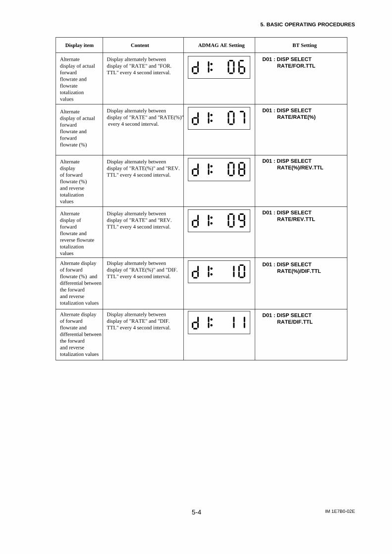
Display item Content ADMAG AE Setting BT Setting
Alternate display of actual forward flowrate and flowrate totalization values
Display alternately between display of "RATE" and "FOR.TTL" every 4 second interval.
Alternatedisplay of actual forward flowrate and forward flowrate (%)
Display alternately between display of "RATE" and "RATE(%)" every 4 second interval.
Alternate display of forward flowrate (%) and reversetotalization values
Alternate display of forward flowrate and reverse flowrate totalization values
Display alternately between display of "RATE(%)" and "REV.TTL" every 4 second interval.
Display alternately between display of "RATE" and "REV.TTL" every 4 second interval.
Alternate display of forward flowrate (%) and differential between the forward and reverse totalization values
Alternate display of forward flowrate and differential between the forward and reverse totalization values
Display alternately between display of "RATE(%)" and "DIF.TTL" every 4 second interval.
Display alternately between display of "RATE" and "DIF.TTL" every 4 second interval.
D01 : DISP SELECT RATE/FOR.TTL
D01 : DISP SELECT RATE(%)/DIF.TTL
D01 : DISP SELECT RATE/RATE(%)
D01 : DISP SELECT RATE(%)/REV.TTL
D01 : DISP SELECT RATE/REV.TTL
D01 : DISP SELECT RATE/DIF.TTL

5. BASIC OPERATING PROCEDURES
IM 1E7B0-02E5-5
(1) Changes in Flow Data Display Items• Shows how the display changes when the flow converter switches are pressed.• See chapter 7 for information on changes using the BT200.
%
SET SHIFT INC SET SHIFT INC SET SHIFT INC
SET SHIFT INC SET SHIFT INC
The display shown when the power is turned on.
Press the SET key to go to the data mode shown above.
Press the INC key twice to display d1:00.
SET SHIFT INC SET SHIFT INC
Press the SET key once and all data starts to flash.
Wait 2 to 3 seconds and press the SET key again to return the hatched portion to its original position.
Press the INC key to select the number of the desired display type.
Press the SET key to move the hached portion (flashes) to the last digit.
SET SHIFT INC
When all setting have been made, hold down the SHIFT key while pressing the SET key to return to original display mode.
00 : Instantaneous flow rates (%)01 : Instantaneous flow rates (actual
meter values)02 : Forward flowrate totalization values03 : Reverse flowrate totalization values04 : Differetial Between the forward and
reverse totalization values05 : Alternate display of forward flowrate
% and forward flowrate totalization values
06 : Alternate display of forward flowrate and flowrate totalization values
07 : Alternate display of forward flowrate and forward flowrate (%)
08 : Alternate display of forward flowrate (%) and reverse totalization values
09 : Alternate display of forward flowrate and reverse flowrate totalization values
10 : Alternate display of forward flowrate (%) and differential between the forward and reverse totalization values
11 : Alternate display of forward flowrate and differential between the forward and reverse totalization values
Selection
%

5. BASIC OPERATING PROCEDURES
IM 1E7B0-02E5-6
5.2.2 Setting Mode
• The setting mode is used for checking parameters and rewriting data.• The following is an overview of the setting mode. See Section 6 "Function and Data
Settings" for detailed information.
(1) Structure of Setting Mode Display• The display consists of two areas ; two digits to the left of the colon and four digits to
the right of it.• Two types of data can be entered : direct entry of numerals and entry of desired data
items using codes.Refer to "Parameter list" in chapter 12 for information on how to change settings.
(2) Procedures for Setting and Changing Data
Item Display Content
SET SHIFT INC
SET SHIFT INC
SET SHIFT INC
SET SHIFT INC
SET SHIFT INC
SET SHIFT INC
Press the SET key to go from the flow rate data display to the setting mode.The delimiter ":" is displayed to indicate that the mode has been swiched.
Press the SHIFT key to move the flashing segment (the selected item)
Use the INC key to change the items displayed in the flashing segment(the selected item).
Parameter 03 contains 5-digit data which cannot bedisplayed as shown on the left but has to be scrolled.
Use the SET key to move the flashing segment (the selected item) to the most significant location of the data area.
Use the INC key to change the data area (numeric data) in the flashing segment (the selected item).
Use the SHIFT key to move the flashing segment (the selected item) within the data area.
① Switch to "Setting Mode"
② Parameter Selection
➂ Data Rewrite
---Continued---
Example of parameter change : Changing the span (number 03) from 1.000 to 1.200
*

5. BASIC OPERATING PROCEDURES
IM 1E7B0-02E5-7
Item Display Content
SET SHIFT INC
SET SHIFT INC
SET SHIFT INC
Press the SET key twice to enter data.(All data will start flashing when the key is pressed the first time.Then wait 2 to 3 seconds before pressing the key the second time.)
Hold down the SHIFT key and press the SET key to switch to the flow rate data display.
➃ Data Input
➄ Switching to Flow Data Entry
First time
Second time
%
(3) Procedures for Changing Decimal PlaceBefore starting this procedure check in the data list if the position of the decimal point for
the desired parameter decimal places can be changed.
Item Display Content
SET SHIFT INC
Press the SHIFT key to move the flashing segment to the decimal point.① Selecting
Decimal Position
SET SHIFT INC
Press the INC key to move the decimal point to the right.➁ Moving Decimal Portion
SET SHIFT INC
Press the SET key twice to enter data.(All data will start flashing when the key is pressed the first time.Then wait 2 to 3 seconds before pressing the key the second tme.)
➂ Data Entry
SET SHIFT INC
First time
Second time
Example of parameter change : Changing the span from 1.000 to 10.00

5. BASIC OPERATING PROCEDURES
IM 1E7B0-02E5-8
(4) Display of 5-digit Data• The data display area has four digits
and can therefore not display span andother 5-digit data parameters.To display such data, the data isautomatically shifted (scrolled) to theleft one digit at a time .When a 5-digit parameter is selected,the delimiter " : " starts to flash.
• When the flashing segment is alignedwith the last digit and the dataincludes a space, the data is displayedas shown 4 on the right.
(5) Display of 6-digit Data• The data display area has four digits
and can therefore not display span and other 6-digit data parameters. (E05 TL SETVALUE is the only 6-digit parameter.)Like 5-digit data, 6-digit data is displayed by automatically shifting (scrolling) it tothe left one digit at a time.
(6) Display and Setting Coded Data• Example of change : Changing from +120 to -120
Item Display Content
SET SHIFT INC
SET SHIFT INC
SET SHIFT INC
The display on right indicates "+120".
Cause the "+" sign to flash.
Press the INC key to change the "+" sign to a "-" sign.
Press the SET key twic.
1. Selecting Coded Data
2. Coded Data Flashes
3. Change of Coded Data
①
➁
➂
➃
➄
➅
➆
1 second
1 second
1 second
1 second
1 second
1 second
(Space)
(Space)
3 seconds
Display example : Display of span 123.45

5. BASIC OPERATING PROCEDURES
IM 1E7B0-02E5-9
5.2.3 Alarm Display Mode
• When an alarm occurs, an alarm number indicating is displayed in place of the normaldisplay mode.However, this happens only when the current display mode is the flow rate data displaymode or when parameter number are being changed in the setting mode. (Alarms are notdisplayed when data items are being changed.)
Flow rate data displayed4 seconds
Alarm 06 is displayed2 seconds
Flow rate data is displayed4 seconds
Alarm 20 has occurred2 seconds
Flow rate data is displayed4 seconds
Alarm (Err) 06 and Alarm (Err) 20 have occurredAlarm (Err) 06 has occurred
Flow rate data displayed4 seconds
Alarm 06 is displayed2 seconds
Flow rate data is displayed4 seconds
%
%
%
%
%
• See the section 8.2 Self-diagnostics function" for information on alarm numbers.

6. FUNCTION AND DATA SETTINGS
IM 1E7B0-02E6-1
6. FUNCTION AND DATA SETTINGS
A Magnetic flowmeter calculates volume flow rate from a minute voltage that corre-sponds to the flow velocity of a fluid and outputs as a 4 to 20mA signal.
The three parameters must be set to obtain a correct signal.Nominal size, flow span and meter factor must be set.In these three factors, Nominal size (unit:mm) and meter factor are set beforeshipment.
This chapter explaines how to set flow span, other functions and data settings.Please set data correctly.
6.1 Setting Flow Span(1) Determing the Flow Span
The flow rate span is the instantaneous flow rate value at which the output current is tobe 20mA.Please determine the span under considering the followings.
• Please set the maximum flow rate at the most variable flow rate line.If the flow rate of the fluid exceeds the flow rate span value, the flow rate thatexceeds this value (20mA or more) is not output and the flowmeter will not displaythe correct flow rate. (108% or more can't be output)
• In a line where the flow rate is comparatively stable, set a value that is 1.5 to 2.0times larger than the normal flow rate.
• Please set a value that will correspond to a flow velocity of 0.3 to 10m/s.Please comfirm the flow velocity by sizing data or parameter No. “ 13”.(Parameter No. “ 13” indicates corresponding flow velocity to set span)
• The basic input value for display is flow span value. It is recommended that theaccuracy of the first digit is in a 0.05 to 0.1% in case inputting the flow rate spanvalue.For example, 30m3/h should be set as 30.00m3/h.
• In a span setting, the maximum value that can set is “30000” except any relationwith decimal position.
Basic Key Operations
Key OperationItem
SET
SHIFT
SET
SHIFT
INC
SET (Twice)
How to change the display into the setting mode?
How to move the cursor on the display during parameter setting?
How to change the display into the data changing mode?
How to move the cursor in the data changing mode?
How to change the data?
How to input the set data?
NOTE
NOTE
You cannot set the leftmost digit of display to numeric value greater than "4". If the leftmost digit of the span must be "4" or more, set the numeric value beginning from the digit second from the left on the display (the fourth digit). If the leftmost digit of the display is set to "3", the digits to its right can be set to "0" only, regardless of the decimal point position.

6. FUNCTION AND DATA SETTINGS
IM 1E7B0-02E6-2
(2) Span Setting using Display Keys (Example setting: 30.00 m3/h)
• Span Value Setting
Switch Operation Display Description
SET SHIFT INC
SET SHIFT INC
SET SHIFT INC
SET SHIFT INC
SET SHIFT INC
SET SHIFT INC
SET SHIFT INC
SET SHIFT INC
SET SHIFT INC
SET SHIFT INC
SET SHIFT INC
Press the SET key during flow rate data display mode to display setting mode shown in the left figure.
Press the SHIFT key to cause the second digit from the left to flash.
Press the INC key to call up parameter number 03.
Press the SET key to move the flashing segment to the first digit in the data area.
Press the INC key to set the first digit to 0.
Press the SHIFT key to move the decimal point.
Press the INC key to move the decimal point to "000.00".*To set a "00000." as the data area is a four digit LCD, the three digits and the space will be displayed as "000".
Press the SHIFT key to move the flashing segment two digits to the right.
Press the INC key to enter "3".
Press the SET key once to cause all the data to flash.*As the data display now will be scrolled, it may not appear as shown in the left figure.
Wait 2 to 3 seconds when the data starts flashing. Then press the SET key to return the flashing segment to the leftmost digit.*This display will also be scrolled to display 5-digit data.
Defalt is set as 1.0000. Change this into 030.00.
(Setting is now completed)
Note : 5-digit span data can be displayed, but only digits will be supplyed at one time. As a result, when the lastdigit is changed, the last digit and the space will be displayed as the last three digits. (See 5.2.2 "Displayof 5-digit data".)
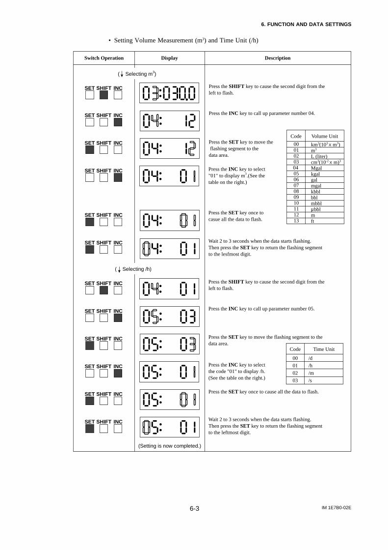
6. FUNCTION AND DATA SETTINGS
IM 1E7B0-02E6-3
• Setting Volume Measurement (m3) and Time Unit (/h)
Switch Operation Display Description
SET SHIFT INC
SET SHIFT INC
SET SHIFT INC
SET SHIFT INC
SET SHIFT INC
SET SHIFT INC
SET SHIFT INC
SET SHIFT INC
SET SHIFT INC
SET SHIFT INC
SET SHIFT INC
Press the SHIFT key to cause the second digit from the left to flash.
Press the INC key to call up parameter number 04.
Press the SET key to move the flashing segment to thedata area.
Press the INC key to select"01" to display m3.(See thetable on the right.)
Press the SET key once tocasue all the data to flash.
Wait 2 to 3 seconds when the data starts flashing.Then press the SET key to return the flashing segmentto the lesfmost digit.
Press the SHIFT key to cause the second digit from theleft to flash.
Press the INC key to call up parameter number 05.
Press the SET key to move the flashing segment to thedata area.
Press the INC key to selectthe code "01" to display /h.(See the table on the right.)
Press the SET key once to cause all the data to flash.
( Selecting m3)
( Selecting /h)
SET SHIFT INC Wait 2 to 3 seconds when the data starts flashing.Then press the SET key to return the flashing segmentto the leftmost digit.
(Setting is now completed.)
Code Volume Unit
Code
00
01
02
03
Time Unit
/d
/h
/m
/s
0001020304 050607080910111213
km3(103 X m3)m3
L (liter)cm3(10-2 X m)3
Mgalkgalgalmgalkbblbblmbblµbblmft

6. FUNCTION AND DATA SETTINGS
IM 1E7B0-02E6-4
6.2 Power Frequency
In case of DC power supply version, setting power frequency is required.
Display Description
Set the value in area where the frequency differs in parameter number "12".Setting Range : 47.00 to 53.00 Hz.
Default : 50.00Hz
6.3 Other Functions and Settings
6.3.1 Pulse Output
(1) Pulse Output Overview• By setting a pulse weight, a scaled pulse is transmitted to external counters and
measuring instruments.
Pulse Output Overview
Item Content
Outputspecifications
Connectingterminals
Pulse width
Output rate
Transistor contact output (contact capacity is 30 V DC, 200 mA)
P+, P- When using these for pulse output, alarm output or status outputare not available as the terminals are used commonly.
Selection: DUTY 50%, 0.5, 1, 20, 33, 50, 100 ms
Min. 0.0001 P/s Max. 1000 P/s
* See page "4.4.6 Connecting external instruments" for information on how to connect external instruments.
P+, P- terminals are for common use with pulse, alarm and other status outputfunctions. Therefore, in case this function is used, other functions are not availableto use.
(2) Procedures for Setting Pulse OutputExample setting : 10 liter output per pulse in a flow rate span of m3/h
Display Description
Select "Pulse output" in parameter number "10".
Code Content
00 Pulse output
0102030405
Alarm outputForward/reverse flow measurementAutomatic two range switchingAlarm output at low flow limitTotalization switch
NOTE

6. FUNCTION AND DATA SETTINGS
IM 1E7B0-02E6-5
Display Description
Select the volume unit for pulse weight using parameter number "F1".
Code Volume Unit
00
01
02
03
04
05
06
Volume unit in that for the flow rate span × 10-9
Volume unit in that for the flow rate span × 10-6
Volume unit in that for the flow rate span × 10-3
Volume unit in that for the flow rate span × 1
Volume unit in that for the flow rate span × 103
Volume unit in that for the flow rate span × 106
Number of pulses output per second at 100% of output
Code Pulse Width
00
01
02
03
04
05
06
Example : When pulses are to be output per same liter with the flow
rate span of m3/h, select "02" since L(liter) = 10-3 × m3
Set the low cut range percentage in parameter "F3".Range of setting : 0 to 100% (of span)
Set pulse weight "10 (L)" in parameter number "E2".
Select the pulse width in parameter number "F4".
Select instantaneous flow rate or flow rate after damping for the pulse output . (The damping time is the value set in "B2".)
Set parameter "n2" to "01" when the pulse output transistor is to be off active.
Since parameter number "F2" is a 5-digit data item, scrolling isnecessary to display all the data. Mind the decimal point whensetting are made. (The decimal point can be moved if required.)
Default : 01(Damped flow rate value)
Default : 00(ON ACTIVE)
Default : 3%
Default : 50%DUTY 50%DUTY (Max. 1000P/s min. 0.0001P/s)
0.5ms (Max. 1000P/s min. 0.0001P/s)
1ms (Max. 500P/s min. 0.0001P/s)
20ms (Max. 25P/s min. 0.0001P/s)
33ms (Max. 15P/s min. 0.0001P/s)
50ms (Max. 10P/s min. 0.0001P/s)
100ms (Max. 5P/s min. 0.0001P/s)
Normally, these are all required settings. The following settings are made depending on the applications
that are used.
*The "n" item can be opened by entering "55" in parameter number "L2".

6. FUNCTION AND DATA SETTINGS
IM 1E7B0-02E6-6
6.3.2 Display of Internal Totalization Values
• The flow converter can display totalization values by setting the pulse weight.
(1) Setting Totalization Pulse WeightExample : Display 10 liter output per pulse in a flow rate span of m3/h
Display Description
Select the volume unit for pulse weight using parameter number "E1".
Code Volume Unit
00
01
02
03
04
05
06
Volume unit in that for the flow rate span × 10-9
Volume unit in that for the flow rate span × 10-6
Volume unit in that for the flow rate span × 10-3
Volume unit in that for the flow rate span × 1
Volume unit in that for the flow rate span × 103
Volume unit in that for the flow rate span × 106
Number of pulses output per second at 100% of output
Example : When pulses are to be output per same liter with the flow rate
span of m3/h, select "02" since L (liter) = 10-3× m3
Set the low cut range percentage in parameter "E3".Range of setting : 0 to 100% (of span)
Select pulse output calculation of instantaneous flow rate or flow rate after damping. (Use parameter "02" to set damping constant.)
Set pulse weight "10 ( L)" in parameter number "E2".
Since parameter number "E2" is a 5-digit data item, scrolling isnecessary to display all the data. Mind the decimal point whensetting are made. (The decimal point can be moved if required.)
Default : 3%
Default : 01(Damped flow rate value)
*The "n" item can be opened by entering "55" in parameter number "L2".

6. FUNCTION AND DATA SETTINGS
IM 1E7B0-02E6-7
6.3.3 Resetting for Totalization Display
• This function is used to reset or preset totalization values of the display.• Hold down the SHIFT key for more than 2 seconds while the totalization values of
the flow rate are displayed to set the totalization value to the value set in parameternumber "E5".
Display Description
Select totalization enable in parameter number "E4"
Code Description
00
01
Totalization preset inhibit
Totalization preset enable
Set the totalization preset value in parameter number "E5". The initial value is 0, if it is no setting, the function is zero setting.
Hold down the SHIFT key for more than 2 seconds while the totalization values of the flow rate reading are displayed to set the totalization value to the value set in parameter number "E5"
Default : 00 (inhibit)
Default : 0
SET SHIFT INC
6.3.4 Damping Time Constant
• The time constant can be changed by setting the parameter No."02" to suppress afluctuation or change a response time.
• The time constant influences to flow rate, pulse output and internal totalization.However, in case "00" is selected in parameter number "n1", the pulse output andinternal totalization are not influenced by it.
Display Description
Set the value in parameter number "02".Setting Range : 0.1 to 200.0 seconds.
Default : 3 seconds

6. FUNCTION AND DATA SETTINGS
IM 1E7B0-02E6-8
6.3.5 Limiting Current Output During Alarm Occurrence
• The current output and display values during alarming can be selected in advance.
Display Description
Set a value for current output to be used during alarms in parameter number "11"
Code Contents
00
01
02
03
2.4mA or less
4.0mA
Hold
21.6mA or more
Default : 00 (2.4 mA or less)
6.3.6 Reversing Flow Direction
• The flow direction is set to "FORWARD" at the factory. This function enables to setflow direction from "FORWARD" to "REVERSE".
Display Description
The flow direction can be set in parameter No."14".
Code Contents
00
01
Forward direction
Reverse direction to flow arrow
Default : 00
6.3.7 Limiting on Current Output
(1) 4 to 20 mA Low Cut Output (Current Output near by 0% Range)• This function makes it possible to reduce fluctuations in the 0% region to reduce it to
0%.
Display Description
Setting range : 0 to 10%
0.5% 0.5%4mA
Output Set value
Input
Hysteresis : 1% fixed
Default : 0(%)
5.6mA(10%)

6. FUNCTION AND DATA SETTINGS
IM 1E7B0-02E6-9
(2) 4 to 20mA Low Limit• This function limits the low end of the analog output.• The default value is -20%, and -10% (2.4mA) as reverse flow limit. Please set in case
other setting is required.• 2.4mA or less output in alarming is also limited.
Display Description
Setting Range : -20 to 100%Default : -20(%)
Output
4mA
5.6mA(10%)Default : -20(%)
(3) 4 to 20mA High Limit• This function limits the high end of the analog output.• The default value is 120% (23.2mA). Please set in case other setting is required.• 21.6mA or more output in alarming is also limited.
Display Description
Setting range : 0 to 120%(4 to 23.2mA)
18.4mA(90%)
Output
Default : 120(%)
4mA

6. FUNCTION AND DATA SETTINGS
IM 1E7B0-02E6-10
6.3.8 Forward and Reverse Flow Measurement
• This function enables to measure forward and reverse flow rate without changing theflowmeter direction.
• By setting reverse range, in case fluids flow to reverse direction the flowmetermeasures it as reverse direction range automatically. In this time, a status signal thatshows changing into the reverse direction is output.
• To set the internal totalizing function for forward direction can also show it forreverse direction by parameter settings.
• P+, P– terminals are used for output connection.
P+, P– terminals are for common use with pulse, alarm and other status outputfunctions. Therefore, in case this function is used, other functions are notavailable to use.
Display Description
(Default : 2%)
F and R flow rate measurement can be selected as “02” in parameter No. “10”.
Reverse direction span can be set in parameter No. “30”.Flow rate unit is the same as forward direction span.
Futher reverse range span should be set in the same number of places of decimals as forward range span.Example: forward flow rate : 1.000 then revers flow rate should be 4.000.
Hysteresis width at switching direction can be set in parameter No. “31”.It is the rate (%) of the smaller span, either forward or reverse span.
Code000102030405
Pulse outputAlarm outputForward / reverse flow measurementAutomatic two range switchingAlarm output at low flow limitTotalization switch
Content
Hysteresis
0%
Flow Rate
Status outputForward flow measurement: OFFReverse flow measurement: ON
When using reversed status (ON/OFF)is required, it can be set in “n2 Output Mode”.
NOTE

6. FUNCTION AND DATA SETTINGS
IM 1E7B0-02E6-11
6.3.9 Automatic Two Range Switching
• When an input exceeds 100% of the first range, the range is automatically transferredto the second range and the status output changes state.
• P+, P– terminals are used for output connection.
P+, P– terminals are for common use with pulse, alarm and other status outputfunctions. Therefore, in case this function is used, other functions are notavailable to use.
Display Description
Default : 10%
Default : 00
Automatic two range transfer can be selected “03” in parameter No. “10”.
Forward second range can be set by calling up parameter No. “33”.Setting restrictions: First range ≤ 2nd range.
Further second range span should be set in the same number of places of decimals as first range span in parameter No. “03”.Example: First range : 1.000 then second range should be 4.000
Hysteresis width at switching range can be set in parameter No. “34”.It is the rate (%) of first range span.
Code000102030405
Pulse outputAlarm outputForward / reverse flow measurementAutomatic two range switchingAlarm output at low flow limitTotalization switch
Content
100%2nd range1st range
Status Output ON
Hysteresis (%)
Output
Flow Rate0 %
Status Output1st range: OFF2nd range: ON
When using reversed status (ON/OFF)is required, it can be set in “n2 Output Mode”.
NOTE

6. FUNCTION AND DATA SETTINGS
IM 1E7B0-02E6-12
6.3.10 Alarm Output at Low Flow Limit (Flow Switch)
• In case flow rate decrease under set level, an status signal is output.
P+, P– terminals are for common use with pulse, alarm and other status outputfunctions. Therefore, in case this function is used, other functions are notavailable to use.
Display Description
Default : 00
(Default : 5%)
(Default : -10%)
Alarm output at low flow limits can be selected “04” in parameter No. “10”.
The Low Limit value can be set in parameter No. “36”as parcentage for 4 to 20 mA.
Hysteresis width is set in parameter No. “37”.
Code000102030405
Pulse outputAlarm outputForward / reverse flow measurementAutomatic two range switchingAlarm output at low flow limit Totalization switch
Content
Output
Hysteresis
StatusOutput
On
low flow limits value.
When using reversed status (ON/OFF)is required, it can be set in “n2 Output Mode”.
NOTE

6. FUNCTION AND DATA SETTINGS
IM 1E7B0-02E6-13
6.3.11 Totalization Switch Output
• In case the Internal Totalization Value increase over set level, an alarm signal isoutput.
P+, P– terminals are for common use with pulse, alarm and other status outputfunctions. Therefore, in case this function is used, other functions are notavailable to use.
Display Description
Default : 0
Default : 00
Totalization switch can be selected as “05” in parameter No. “10”.
Switch level can be selected by calling up parameter No. “06”.
Code000102030405
Pulse outputAlarm outputForward / reverse flow measurementAutomatic two range switchingAlarm output at low flow limitTotalization switch
Content
Totalization
999999
Setting value 10000
StatusOutput
ON
Input
When using reversed status (ON/OFF)is required, it can be set in “n2 Output Mode”.
NOTE

6. FUNCTION AND DATA SETTINGS
IM 1E7B0-02E6-14
6.3.12 Alarm Output
• This function is for status output from PLS/ALM+, PLS/ALM– terminals, when analarm occurs.
P+, P– terminals are for common use with pulse, alarm and other status outputfunctions.Therefore, in case this function is used, other functions are not available to use.
• All of the alarms are able to output except empty pipe detection function that can beselected in parameter No. “n7” as out of selection.
• The status goes from close to open (OFF) during alarming.
Display Description
Default : 00
Default : 00
* Item "N" can be opened by entering "55" in parameter number "L2".
The alarm output can be selected “01” in parameter No. “10” and P+, P– terminals are only for alarm output.
The empty pipe output selection can be set in parameter No. “n7”.
Code000102030405
Pulse outputAlarm outputForward / reverse flow measurementAutomatic two range switchingAlarm output at low flow limitTotalization switch
Content
ContentCode0001
ALARMNO ALARM
6.3.13 Data Setting Enable / Inhibit
• This function can inhibit to change all data except parameter No. “ L1”.However, auto zero adjustment function can work, if it has been set in parameter No.“C1”.And the preset totalization value function also can work, if it has been set in param-eter No. “E4”.
Display Description
Code Content
00
01
INHIBIT
ENABLE
The data setting inhibit item can be set "00" in parameter number "L1".
Default : 01
NOTE

6. FUNCTION AND DATA SETTINGS
IM 1E7B0-02E6-15
6.3.14 Procedure of Selecting Special Application Items
• Only the special apprication (“n” items) shipped being unpublished.In case the “n” items should be used, it can be set “55” in parameter No. “L2”.
Display Description
Code Content
00
01
Accessible up to L parameters
Accessible up to n parameters
It is possible to open up to item n when "55" is entered in parameter number
"L2".
Default : 00
6.3.15 Rate Limit
• This function is used to remove noise that cannot be removed by increasing thedamping time constant.
• In case unexpected noise from step signal or slurry is entered, a basis is set torecognize that signal is flow rate or noise.The recoginition depends on rate limit value (upper and lower limit) and dead time(sampling time).
• Determination of rate limit value and dead time.
Rate limit value:Determine the level to reduce outputfluctuation.For example, reducing 2% or morefluctuation by setting as 2% to reduce.
2%2%
T0
T0
Dead time T0:Please determine the dead timedepending on output fluctuation width.In case of noise of which is longerthan the dead time, please set the dead time longer.
• Signal processing procedures:The function sets a certain upper and lower limit (rate limit value) for first orderdelay response values of flow rate data obtained in a previous sampling. If currentlysampled flow rate data exceeds or goes below the limit is regarded as current flowrate value. Signals whose protruding portions show the same trends during a certainnumber of sampling times (dead time)are identified as flow rate signals.
Example 1: Step Input
1%
10%Step Signal
Flow rate value after rate limiting
Flow rate value afterdamping
(3)(1)
(2)
9 18
(4)
63.2%
Input: 0 to 10%Damping time constant: 3 sec.Dead time: 3 sec.Rate limit value: 1%
Dead time: 3 sec.
Sampling times

6. FUNCTION AND DATA SETTINGS
IM 1E7B0-02E6-16
(1) Shows 1% response cause of excessive signal beyond the rate limit. However, actualoutput is under damping that described by a solid line.
(2) Shows the flow rate signal (1%) of just after damping calculation (1) and rate limitvalue.
(3) This signal is recognized as a flow rate signal since it does not return to within therate limit value within the dead time.
(4) The output signal follows the damping curve and tracks the step signal.
Example 2: Slurry Noise
Slurry Noise
Flow rate value after rate limiting and damping.
Flow rate value afterrate limiting
Dead time: 1 sec.
+1%
–1%
Input: 0 to 10%Damping time constant: 1 sec.Dead time : 1 sec.Rate limit value: 1%
The left figure shows that the slurrynoise is not a flow rate signal.
Time
Display Description
Set a rate limit value in parameter number "n3".
Setting Range : 0 to 10%.
Set the dead time in parameter number "n4".
Setting Range : 0 to 15 seconds.
Default : 5%
Default : 0%
*Item "n" can be opened by entering "55" in parameter number "L2".
6.3.16 Pulsating Flow
• The pulsating flow produced by a plunger pump results in inaccurate average flowrate values. This function makes it possible to accurately track flow rate changes andcontrol calculation.
Display Description
Select "01" (pulsating flow counteraction) in parameter number "n6".
Code Contents
00
01
Nomal
Counteracting pulsating flow
Default : 00
*Item "n" can be opened by entering "55" in parameter number "L2".

7. OPERATION VIA BRAIN TERMINAL
IM 1E7B0-02E7-1
7. OPERATION VIA BRAIN TERMINAL
Products with optional code / BR (BRAIN communication function) come equippedwith a BRAIN communication function which allows them to communicate withdedicated BRAIN terminals (BT) or CENTUM systems. In the BRAIN series communi-cations system, a ±2 mA, 2.4 kHz modulated signal is superimposed onto the 4 to 20mA DC analog signal for data transmission. Since the modulated wave is an AC signalsuperimposed on the analog signal will cause no error in the DC component of theanalog signal. Thus, monitoring can be performed via communications while theADMAG AE is online.
A BRAIN terminal can be connected to the terminals shown in Figure 7.1 on productsthat are not provided with / BR (BRAIN communication function).
7.1 Operation Via the BT200This section describes the operation procedures using a BRAIN terminal. For details onthe functions of the ADMAG AE, see Chapter 6, "Function and Data Settings." Andalso, see the "BT200 Instruction Manual" (IM 1C0A11-01E) for more detailed informa-tion.
7.1.1 BT200 Connections
(1) Connecting BT200 to Converter
-CoCA-(Communication) is displayed during communication.
Use these terminals when the product does not have a display.
Figure 7.1 Connection of BRAIN terminal to Converter
For products not provided with / BR (BRAIN communication function), the terminalsfor BRAIN communication are provided on the circuit board. Please connect BT200 tothe terminals on the circuit board directly.
(2) Connecting the BT200 to a 4 to 20 mA DC Transfer LineThe communication signal of the ADMAG AE with / BR is superimposed onto the 4 to20 mA DC analog signal to be transferred.
Intermediateterminals
4 to 20 mA DC signaltransmission line
Control room
Terminal boardReceiver
Receiver resistance,250 Ω to 600 Ω
Figure 7.2 Communicating via a 4 to 20 mA DC Signal Line
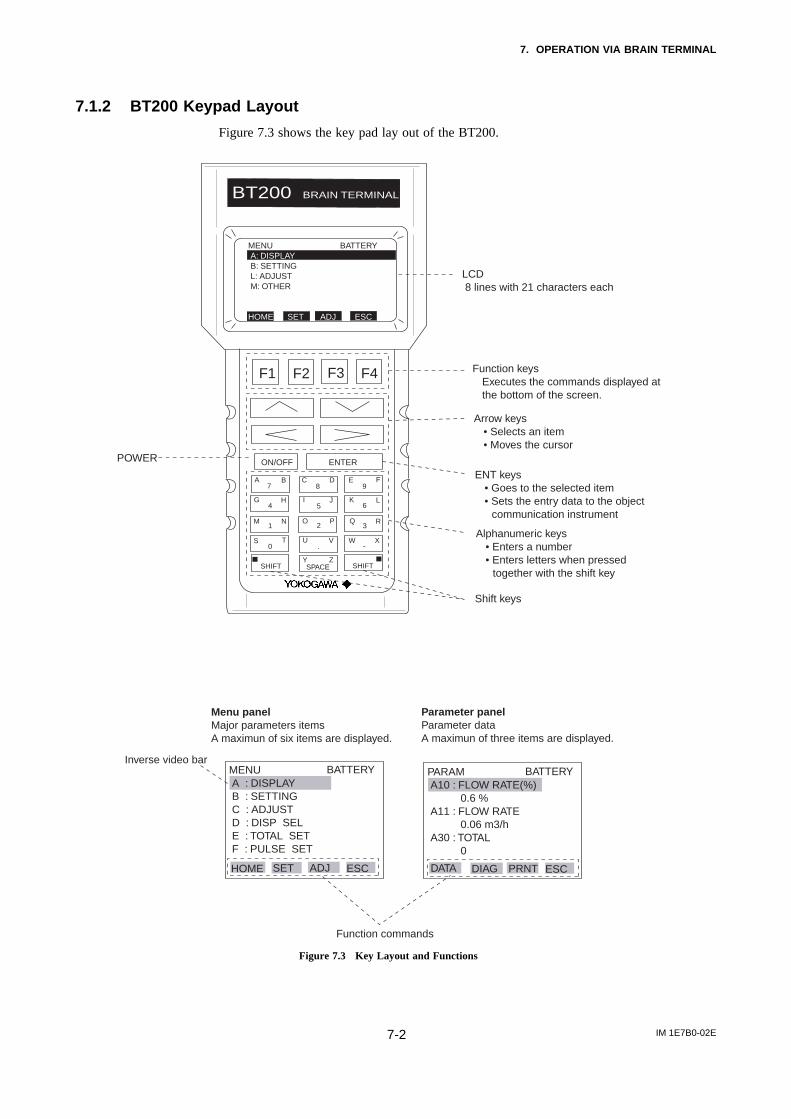
7. OPERATION VIA BRAIN TERMINAL
IM 1E7B0-02E7-2
7.1.2 BT200 Keypad Layout
Figure 7.3 shows the key pad lay out of the BT200.
BT200 BRAIN TERMINAL
F1 F2 F3 F4
ON/OFF ENTER
Function keysExecutes the commands displayed atthe bottom of the screen.
Arrow keys• Selects an item• Moves the cursor
ENT keys• Goes to the selected item• Sets the entry data to the object
communication instrument
A B7
C D E F8 9
G H4
I J5
K L6
M N O P Q R
S T U V W X
Y Z
1 2 3
0 . -
SHIFT SPACE SHIFT
Alphanumeric keys• Enters a number• Enters letters when pressed
together with the shift key
Shift keys
MENU A : DISPLAY B : SETTING C : ADJUST D : DISP SEL E : TOTAL SET F : PULSE SET
BATTERY
HOME SET ADJ ESC
PARAM A10 : FLOW RATE(%) 0.6 % A11 : FLOW RATE 0.06 m3/h A30 : TOTAL 0
BATTERY
DIAG PRNT ESCDATA
Function commands
Parameter panelParameter dataA maximun of three items are displayed.
LCD 8 lines with 21 characters each
POWER
Inverse video bar
Menu panelMajor parameters itemsA maximun of six items are displayed.
MENU BATTERY A: DISPLAY B: SETTING L: ADJUST M: OTHER
HOME SET ADJ ESC
Figure 7.3 Key Layout and Functions

7. OPERATION VIA BRAIN TERMINAL
IM 1E7B0-02E7-3
7.1.3 Major BT200 Key Functions
(1) Entry of Alphanumeric CharactersNumbers, codes and letters can be entered in combinations of the alphanumeric keys andthe SHIFT key.
• Entry of numbers, codes and a space (0 to 9, . , -, )Entering of them is possible by using the alphanumeric keys.
Example of entry Key Operation
1 -0.3
-4.3w x
–
M N
1
G H
4
Y Z
SPACE
U V
w x
–
Q R
3
S T
0
U V Q R
3
.
.
• Entry of lettersPress an alphanumeric key while one of the SHIFT keys is pressed and the letter on thesame side of the key as the shift key that is pressed can be entered. Press the SHIFT keyeach time when entering a letter.
SHIFT
A B
7
SHIFT
The letter on the left side of the alphanumeric key is entered.
The letter on the right side of the alphanumeric key is entered.
Example of entry Key operation
J.B
WIC
SHIFT
SHIFT
W X I J
I J
–
5
SHIFT
U V
•
5
SHIFT
A B
7
SHIFT
C D
8
• Selection of uppercase / lowercase of lettersUppercase and lowercase letters can be selected alternately by pressing the function key[F2] (CAPS).
CODE CAPS CLR ESC
Entry of uppercase letters
F1 F2 F3 F4
CODE caps CLR ESC
Entry of lowercase letters
F1 F2 F3 F4
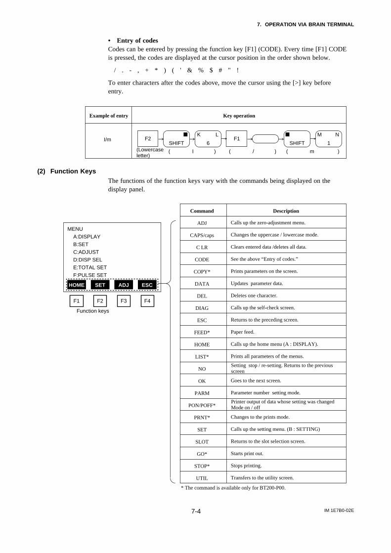
7. OPERATION VIA BRAIN TERMINAL
IM 1E7B0-02E7-4
• Entry of codesCodes can be entered by pressing the function key [F1] (CODE). Every time [F1] CODEis pressed, the codes are displayed at the cursor position in the order shown below.
/ . - , + * ) ( ' & % $ # " !
To enter characters after the codes above, move the cursor using the [>] key beforeentry.
Example of entry Key operation
I/mSHIFT
K L
6F2
SHIFT
M N
1F1
(Lowercase letter)
( I ) ( / ) ( m )
(2) Function KeysThe functions of the function keys vary with the commands being displayed on thedisplay panel.
Command
ADJ
CAPS/caps
C LR
CODE
COPY*
DATA
DEL
DIAG
ESC
FEED*
HOME
LIST*
NO
OK
PARM
PON/POFF*
PRNT*
SET
SLOT
GO*
STOP*
UTIL
Description
Calls up the zero-adjustment menu.
Changes the uppercase / lowercase mode.
Clears entered data /deletes all data.
See the above “Entry of codes.”
Prints parameters on the screen.
Updates parameter data.
Deletes one character.
Calls up the self-check screen.
Returns to the preceding screen.
Paper feed.
Calls up the home menu (A : DISPLAY).
Prints all parameters of the menus.
Goes to the next screen.
Parameter number setting mode.
Changes to the prints mode.
Calls up the setting menu. (B : SETTING)
Returns to the slot selection screen.
Starts print out.
Stops printing.
Transfers to the utility screen.
MENU
A:DISPLAY
B:SET
C:ADJUST
D:DISP SEL
E:TOTAL SET
F:PULSE SET
HOME SET ADJ ESC
F1 F2 F3 F4
Function keys
Setting stop / re-setting. Returns to the previousscreen
Printer output of data whose setting was changed Mode on / off
* The command is available only for BT200-P00.

7. OPERATION VIA BRAIN TERMINAL
IM 1E7B0-02E7-5
7.1.4 Displaying Flow Rate Data
Flow rate data can be displayed on the BT200 screen according to the followingprocedure.
- -WELCOME- -BRAIN TERMINAL ID:BT200
Check cable connectionand press the ENT key.
Turn the power on and the screen on the left appears after "please wait..." is displayed for a few seconds.
ON/OFF
PARAMETER01:MODEL AE14-02:TAG NO.
03:SELF CHECK GOOD
MENUA:DISPLAYB:SETC:ADJUSTD:DISP SELE:TOTAL SETF:PULSE SET
PARAMA10:FLOW RATE(%) 0.6%A20:FLOW RATE 0.06m3/hA30:TOTAL 0
PARAMA10:FLOW RATE(%) 0.6%A20:FLOW RATE 0.06m3/hA30:TOTAL 0
HOME SET ADJ ESC
UTIL FEED
Pressing the ENTER key causes the initial data screen on the left to be displayed.
Pressing the F4 key or the ENTER key causes the menu screen on the left to be displayed.
F1
F4
ENTER
ENTER
ENTER
F2 F3 F4
OK
or
With "A : DISPLAY" displayed on the menu panel in the inverse video bar, press the ENTER key and the flow data screen appears.
A maximum of three data items can be displayed on one screen.
Data are communicated at an interval of 5 seconds. Thus, the data are updated every 5 seconds.
The arrow keys, [ ], [ ] or [ ], [ ], are used for page feeds or item selection.
F1: Updates the current data. Pressing this key causes forcible communication with the connected instruments and the data of the instruments are loaded to be read.
F2: Displays the self-check screen.F3: Displays the parameter print screen.F4: Returns to the previous panel (menu panel).
Execution of the function keys
The tag number specified upon ordering is entered.
Inverse video bar
< ><>DATA DIAG ESCPRNT
DATA DIAG PRNT ESC
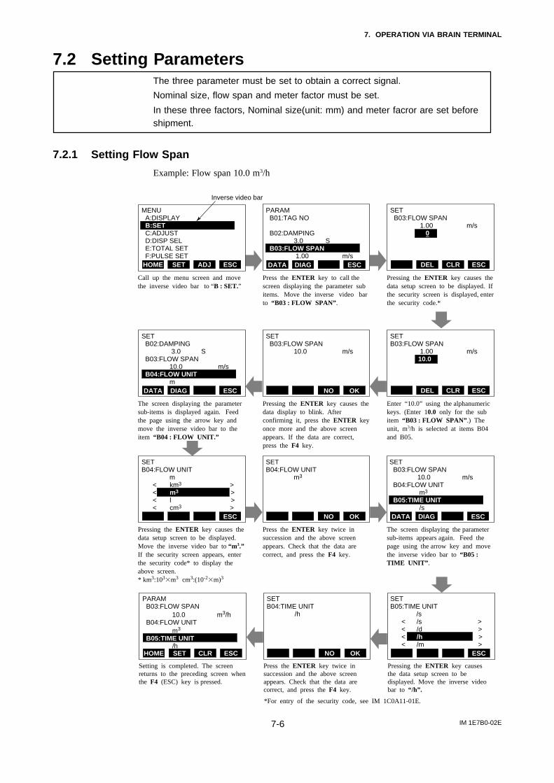
7. OPERATION VIA BRAIN TERMINAL
IM 1E7B0-02E7-6
7.2 Setting ParametersThe three parameter must be set to obtain a correct signal.
Nominal size, flow span and meter factor must be set.
In these three factors, Nominal size(unit: mm) and meter facror are set beforeshipment.
7.2.1 Setting Flow Span
Example: Flow span 10.0 m3/h
PARAM B01:TAG NO
B02:DAMPING 3.0 S B03:FLOW SPAN 1.00 m/s
SET B03:FLOW SPAN 1.00 m/s 0
CLR ESCDEL
MENU A:DISPLAY B:SET C:ADJUST D:DISP SEL E:TOTAL SET F:PULSE SETHOME ADJ ESCSET ESCDIAGDATA
Call up the menu screen and move the inverse video bar to “B : SET.”
Press the ENTER key to call the screen displaying the parameter sub items. Move the inverse video bar to “B03 : FLOW SPAN”.
Pressing the ENTER key causes the data setup screen to be displayed. If the security screen is displayed, enter the security code.*
SET B03:FLOW SPAN 10.0 m/s
CLR ESCDELOKNO
SET B02:DAMPING 3.0 S B03:FLOW SPAN 10.0 m/s B04:FLOW UNIT m
ESCDIAGDATA
The screen displaying the parameter sub-items is displayed again. Feed the page using the arrow key and move the inverse video bar to the item “B04 : FLOW UNIT.”
Pressing the ENTER key causes the data display to blink. After confirming it, press the ENTER key once more and the above screen appears. If the data are correct, press the F4 key.
Enter “10.0” using the alphanumeric keys. (Enter 10.0 only for the sub item “B03 : FLOW SPAN”.) The unit, m3/h is selected at items B04 and B05.
SETB04:FLOW UNIT m3
OKNO
SETB04:FLOW UNIT m < km3 > < m3 > < l > < cm3 >
ESC
SET B03:FLOW SPAN 10.0 m/s B04:FLOW UNIT m3
B05:TIME UNIT /s
ESCDIAGDATA
Pressing the ENTER key causes the data setup screen to be displayed. Move the inverse video bar to “m3.” If the security screen appears, enter the security code* to display the above screen. * km3:103m3 cm3:(10-2m)3
Press the ENTER key twice in succession and the above screen appears. Check that the data are correct, and press the F4 key.
The screen displaying the parameter sub-items appears again. Feed the page using the arrow key and move the inverse video bar to “B05 : TIME UNIT”.
Setting is completed. The screen returns to the preceding screen when the F4 (ESC) key is pressed.
Press the ENTER key twice in succession and the above screen appears. Check that the data are correct, and press the F4 key.
Pressing the ENTER key causes the data setup screen to be displayed. Move the inverse video bar to “/h”.
SETB04:TIME UNIT /h
OKNO
PARAM B03:FLOW SPAN 10.0 m3/h B04:FLOW UNIT m3
B05:TIME UNIT /h
ESCSET CLRHOME
SETB05:TIME UNIT /s < /s > < /d > < /h > < /m >
ESC
SETB03:FLOW SPAN 1.00 m/s 10.0
*For entry of the security code, see IM 1C0A11-01E.
Inverse video bar

7. OPERATION VIA BRAIN TERMINAL
IM 1E7B0-02E7-7
7.2.2 Power Frequency
In case of DC power supply version, setting power frequency is required.
Display Description
Set value in areas where the frequency differs in "B12 : POWER FREQ".Default:50.00Hz.Setting Range : 47.00 to 53.00Hz
PARAM B10:OUTPUT FUNC
PULSE OUT B11:4-20ALM OUT 2.4mA OR LESS B12:POWER FREQ 50.03HzDATA ESCDIAG
7.2.3 Pulse Output (Refer to 6.3.1)
Example setting : 10 L output per pulse in a flow rate span of m3/h
PARAM F01:PULSE UNIT m UNIT/P F02:PULSE SCALE 10 m UNIT/P F03:PULSE LOWCUT 3. %
Display Description
Code Volume unit
n UNIT/P
m UNIT/P
m UNIT/P
UNIT/P
k UNIT/P
M UNIT/P
P ULSE/s
Volume unit in that for the flow rate span × 10-9
Volume unit in that for the flow rate span × 10-6
Volume unit in that for the flow rate span × 10-3
Volume unit in that for the flow rate span × 1
Volume unit in that for the flow rate span × 103
Volume unit in that for the flow rate span × 106
Number of pulses output per second at 100% of output
Code Pulse width
50%DUTY
0.5ms
1ms
20ms
33ms
50ms
100ms
Example) When pulses are to be output per same liter with the flow rate span
of m3/h, select "m UNIT/P" since a L(liter) = 10-3 × m3
Set the low cut range percentage in parameter "F03". Range of setting : (0 to 100% of span)
The pulse output terminals (P+, P-) are also used for alarms. Select "Pulse output" in parameter number "B10".
Select the volume unit for the pulse weight in parameter number "B04".
Select the pulse width in parameter number "F04"
Set the pulse weight "10 ( L )" in parameter number "F02".
*Since parameter number "F02" is a 5-digit data item, scrolling is necessary to display all the data. Mind the decimal point when seting are
made. (The decimal point can be moved if required.)
(Max. of 1000P/s Min. 0.0001P/s)
(Max. of 1000P/s Min. 0.0001P/s)
(Max. of 500P/s Min. 0.0001P/s)
(Max. of 25P/s Min. 0.0001P/s)
(Max. of 15P/s Min. 0.0001P/s)
(Max. of 10P/s Min. 0.0001P/s)
(Max. of 5P/s Min. 0.0001P/s)
PARAM B10:OUTPUT FUNC
PULSE OUT B11:4-20ALM OUT 2.4mA OR LESS B12:POWER FREQ 50.03HzDATA ESCDIAG
DATA ESCDIAG
PALAM F02:PULSE UNIT 10 m UNIT/P F03:PULSE LOWCUT 3. % F04:PULSE WIDTH 50% DUTYDATA ESCDIAG
ESC
PULSE OUT
ALARM OUT
BI DIRECTION
AUTO 2 RANGES
LOW ALARM
TOTAL SWTICH
Pulse output
Alarm output
Forward / reverse flow measurement
Automatic two range switching
Alarm output at low flow limits
Totalization switch
Code Content
PARAM N01:TOTAL/PULSE DAMP N02:OUTPUT MODE ON N03:RATE LIMIT 5. %DATA ESCDIAG
Normally, these are all required settings.
The following settings are made depending on the application that is used.
Select instantaneous flow rate or flow rate after damping data for the pulse output. (The damping time value is the value set in "02".)
Default : DAMP
Set parameter "02" to "OFF" when the pulse output transistor is to be off-active.
* The "N" item can be opened by entering"55" in parameter number "L02".

7. OPERATION VIA BRAIN TERMINAL
IM 1E7B0-02E7-8
7.2.4 Display of Internal Totalization Values (Refer to 6.3.2)
Example : 10 L output per pulse in a flow rate span of m3/h
Display Description
Code Volume unit
n UNIT/P
UNIT/P
m UNIT/P
UNIT/P
k UNIT/P
M UNIT/P
PULSE/s
Volume unit used in that for the flow rate span × 10-9
Volume unit used in that for the flow rate span × 10-6
Volume unit used in that for the flow rate span × 10-3
Volume unit used in that for the flow rate span × 1
Volume unit used in that for the flow rate span × 103
Volume unit used in that for the flow rate span × 106
Number of pulse output per second at 100% of output
Example) When pulses are to be output per same liter with the flow rate
span of m3/h, select “m UNIT/P” since a L(liter) =10-3 × m3
Set the pulse weight “10 (L)” in parameter number “E02.”
Set the low cut range percentage in parameter “E03.” Range of setting : (0 to 100% of span)
Select instantaneous flow rate or flow rate after damping for the pulse output. (The damping time value is the value set in “B02.” ) Default : DAMP (damped flow rate data)
Select the volume unit for the pulse weight in parameter number “E01.”
PARAM E01:TOTAL UNIT m UNIT/P E02:TOTAL SCALE 10 m UNIT/P E03:TOTAL LOWCUT 3. %DATA ESCDIAG
PARAM N01:TOTAL/PULSE DAMP N02:OUTPUT MODE ON N03:RATE LIMIT 5. %DATA ESCDIAG
* The "N" item can be opened by entering "55" in parameter number "L02".
7.2.5 Resetting for Totalization Display (Refer to 6.3.3)
Display Description
Code Description
ENABLE
INHIBIT
Totalization presetting enabled
Totalization presetting disabled
Select totalization enable in parameter number “E04.”
Set the totalization preset value in parameter number “E05.” The default is 0 and if the setting is omitted, the parameter functions reset to 0.
If the ENT key is pressed twice while “A30 : TOTAL” is displayed on the setting screen, the totalization value (A30 : TOTAL) will be replaced with the values set in “E05.”
PARAM E04:TOTAL SET ENABLE E05:TL SET VALUE 0 E10:TOTAL SWITCH 0DATA ESCDIAG
PARAM A10:FLOW RATE(%) 50 .0 % A20:FLOW RATE 50 .0 m3/h A30:TOTAL 12345DATA PRNT ESCDIAG
SETTING A30:TOTAL 0
CLR ESC
ENTER

7. OPERATION VIA BRAIN TERMINAL
IM 1E7B0-02E7-9
7.2.6 Damping Time Constant (Refer to 6.3.4)
Display Description
PARAM B01:TAG NO B02:DAMPING 3.0 s B03:FLOW SPAN 1.00 m/sDATA ESCDIAG
Set the value in parameter number "B02." Setting Range : 0.1 to 200.0 seconds.
7.2.7 Current Output during Alarm Occurrence (Refer to 6.3.5)
Display Description
PARAM B10:OUTPUT FUNC PULSE OUT B11:4-20 ALM OUT 2.4mA OR LESS B12:POWER FREQ 50.03HzDATA ESCDIAG
Set the value for current output to be used during alarms in parameter "B11."(Default : 2.4 mA or less)
2.4mA OR LESS
4.0mA
HOLD
21.6mA OR MORE
2.4 mA or less
4.0 mA
Fixed to output when alarm is
generated.
21.6 mA or more
ContentCode
7.2.8 Reversing Flow Direction (Refer to 6.3.6)
Display Description
PARAM B13:VELOCITY CHK 5 m/s B14:FLOW DIR REVERSE B60:SELF CHECK GOOD m/sDATA ESCDIAG
The flow direction can be set in parameter number "B14"
Code Description
FORWARD
REVERSE
Forward directionReverse direction to flow arrow
7.2.9 Limiting Current Output (Refer to 6.3.7)
(1) 4 to 20 mA low cut output (Current Output near by 0% Range)
Display Description
PARAM G01:4-20 LOW CUT 10 % G02:4-20 LOW LMT -20 % G03:4-20 H LMT 110 %DATA ESCDIAG
Setting range : 0 to 10%
0.5% 0.5%4mA
Output Set value
Hysteresis:1% fixed
5.6mA(10%)
Default:0%

7. OPERATION VIA BRAIN TERMINAL
IM 1E7B0-02E7-10
(2) 4 to 20 mA Low Limit
Display Description
Setting Range : -20 to 100%Default : -20%
DATA ESCDIAG
PARAM G01:4-20 LOW CUT 0 % G02:4-20 LOW LMT 10 % G03:4-20 H LMT 110 % 4mA
Output
5.6mA(10%)
(3) 4 to 20 mA High Limit
Display Description
Setting range : 0 to 120% Default : 120%
18.4mA(90%)
OutputPARAM G01:4-20 LOW CUT 0 % G02:4-20 LOW LMT -20 % G03:4-20 H LMT 90 %DATA ESCDIAG
7.2.10 Forward and Reverse Flow Measurement (Refer to 6.3.8)
Display Description
PARAM B09:HIGH MF 1.0000 B10:OUTPUT FUNC BI DIRECTION B11:4-20 ALM OUT 2.4mA OR LESSDATA ESCDIAG
DATA ESCDIAG
PULSE OUT
ALARM OUT
BI DIRECTION
AUTO 2 RANGES
LOW ALARM
TOTAL SWTICH
Pulse output
Alarm output
Forward / reverse flow measurement
Automatic two range switching
Alarm output at low flow limits
Totalization switch
PARAMB30 :REV. SPAN
B31 :BI. DIREC HYS
B33 :FOR. SPAN2
Select "BI DIRECTION" (Direct / reverse flow measuring mode) in parameter number "B10 ".
Reverse direction span can be set in parameter No."B30".Flow rate unit is the same as forward direction span.
Further reverse range span should be set in the same number of places of decimals as forward range span.Example: forward flow rate : 1.000 then reverse flow rate should be 4.000.
Hysteresis width at switching direction can be set in parameter No."B31".It is the rate(%) of the smaller span, either forward or reverse span.
Code Content

7. OPERATION VIA BRAIN TERMINAL
IM 1E7B0-02E7-11
7.2.11 Automatic Two Range Switching (Refer to 6.3.9)
Display Description
PULSE OUT
ALARM OUT
BI DIRECTION
AUTO 2 RANGES
LOW ALARM
TOTAL SWTICH
Pulse output
Alarm output
Forward / reverse flow measurement
Automatic two range switching
Alarm output at low flow limits
Totalization switch
PARAM B09:HIGH MF 1.0000 B10:OUTPUT FUNC AUTO 2 RANGES B11:4-20 ALM OUT 2.4mA OR LESSDATA ESCDIAG
DATA ESCDIAG
PARAMB31 :BI DIREC HYS
B33 :FOR. SPAN2
B34 :AUTO RNG HYS
Select "AUTO 2 RANGES" (Automatic two range transfer) in parameter number "B10".
Forward second range can be set by calling up parameter No. B33 .Setting restrictions: First range ≤ 2nd range.
Further second range span should be set in the same number of places of decimals as first range span in parameter No. B03 .Example: First range : 1.000 then second range should be 4.000
Hysteresis width at switching range can be set in parameter No. B34 .It is the rate (%) of first range span.
ContentCode
7.2.12 Alarm Output at Low Flow Limits (Flow Switch) (Refer to 6.3.10)
Display Description
PULSE OUT
ALARM OUT
BI DIRECTION
AUTO 2 RANGES
LOW ALARM
TOTAL SWTICH
Pulse output
Alarm output
Direct / reverse flow measurement
Automatic two range transfer
Alarm output at low flow limits
Totalization switch
PARAM B09:HIGH MF 1.0000 B10:OUTPUT FUNC LOW ALARM B11:4-20 ALM OUT 2.4mA OR LESSDATA ESCDIAG
DATA ESCDIAG
PARAMB34 :AUTO RNG HYS
B36 :LOW ALARM
B37 :L. ALARM HYS
Select "LOW ALARM " (Alarm output at low flow limits) in parameter number "B10 ".
Set the comparison level in parameter number "B36 ".
Set the hysteresis in parameter "B37 ".
ContentCode
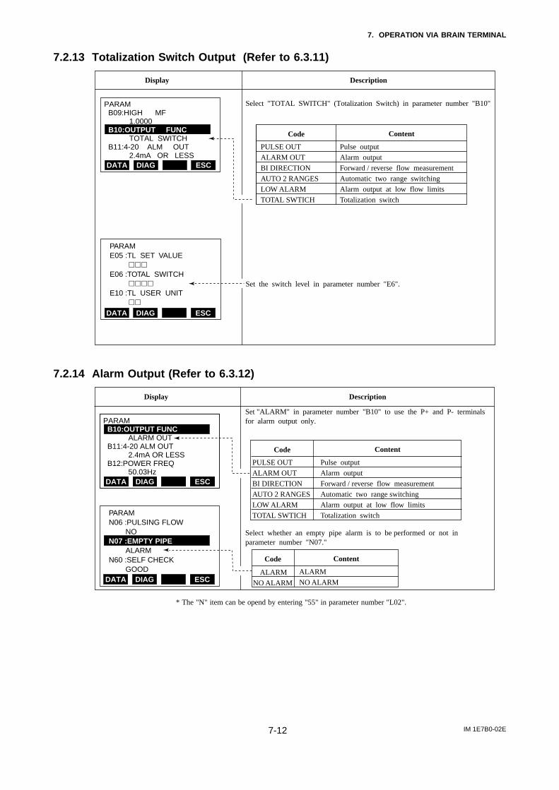
7. OPERATION VIA BRAIN TERMINAL
IM 1E7B0-02E7-12
7.2.13 Totalization Switch Output (Refer to 6.3.11)
Display Description
Pulse output
Alarm output
Forward / reverse flow measurement
Automatic two range switching
Alarm output at low flow limits
Totalization switch
PULSE OUT
ALARM OUT
BI DIRECTION
AUTO 2 RANGES
LOW ALARM
TOTAL SWTICH
PARAM B09:HIGH MF 1.0000 B10:OUTPUT FUNC TOTAL SWITCH B11:4-20 ALM OUT 2.4mA OR LESSDATA ESCDIAG
DATA ESCDIAG
PARAME05 :TL SET VALUE
E06 :TOTAL SWITCH
E10 :TL USER UNIT
Select "TOTAL SWITCH" (Totalization Switch) in parameter number "B10"
Set the switch level in parameter number "E6".
ContentCode
7.2.14 Alarm Output (Refer to 6.3.12)
PARAM B10:OUTPUT FUNC ALARM OUT B11:4-20 ALM OUT 2.4mA OR LESS B12:POWER FREQ 50.03Hz
Display Description
Set "ALARM" in parameter number "B10" to use the P+ and P- terminals for alarm output only.
Select whether an empty pipe alarm is to be performed or not in parameter number "N07."
Code Content
ALARM
NO ALARM
ALARM
NO ALARM
DATA ESCDIAGDATA ESCDIAG
DATA ESCDIAG
PARAMN06 :PULSING FLOW NOBN07 :EMPTY PIPE ALARMN60 :SELF CHECK GOOD
PULSE OUT
ALARM OUT
BI DIRECTION
AUTO 2 RANGES
LOW ALARM
TOTAL SWTICH
Pulse output
Alarm output
Forward / reverse flow measurement
Automatic two range switching
Alarm output at low flow limits
Totalization switch
Code Content
* The "N" item can be opend by entering "55" in parameter number "L02".

7. OPERATION VIA BRAIN TERMINAL
IM 1E7B0-02E7-13
7.2.15 Data Setting Enable / Inhibit (Refer to 6.3.13)
• This function makes it possible to inhibit all data changes (except L1). However,automatic zero adjustment can be made if the automatic zero-adjustment function isenabled (set in C1). Also, totalization presetting can be done if the totalizationpresetting function is enabled (set in E4).
Display Description
Selecting "INHIBIT" in parameter number "L01" disables data setting.
Code Content
ENABLE
INHIBIT
Data setting enabled.
Data setting disabled.
PARAM L01:TUNING INHIBIT L02:KEY 00 L60:SELF CHECK GOODDATA ESCDIAGDATA ESCDIAG
Default
7.2.16 Procedure of Selecting Special Application Items (Refer to 6.3.14)
Displayed Description
It is possible to open up to item N when "55" is entered in parameter number "L02."
Code Content
00
55
Accessible up to L parameters
Accessible up to N parameters
PARAM L01:TUNING INHIBIT L02:KEY 55 L60:SELF CHECK GOODDATA ESCDIAGDATA ESCDIAG
Default
7.2.17 Rate Limit (Refer to 6.3.15)
Display Description
PARAM N03:RATE LIMIT 5 % N04:DEAD TIME 0 s N05:POWER SYNCH YESDATA ESCDIAGDATA ESCDIAG
Set the rate limit value in parameter number "N03." Range of possible settings : 0 to 10%.
Set the dead time in parameter number "N04." Range of possible settings : 0 to 15 seconds. Default : 0 (Rate limit function off)
* The "N" item can be opened by entering "55" in parameter number "L02".
7.2.18 Pulsating Flow (Refer to 6.3.16)
Display Description
PARAM N04:DEAD TIME 0 N05:POWER SYNCH YES N06:PULSING FLOW YESDATA ESCDIAG
Select “YES” (pulsating flow counteraction) in parameter number “N06” (Default : NO)
Code Content
NO
YES
NormalCounteracting pulsating flow
* The "N" item can be opened by entering "55" in parameter number "L02".
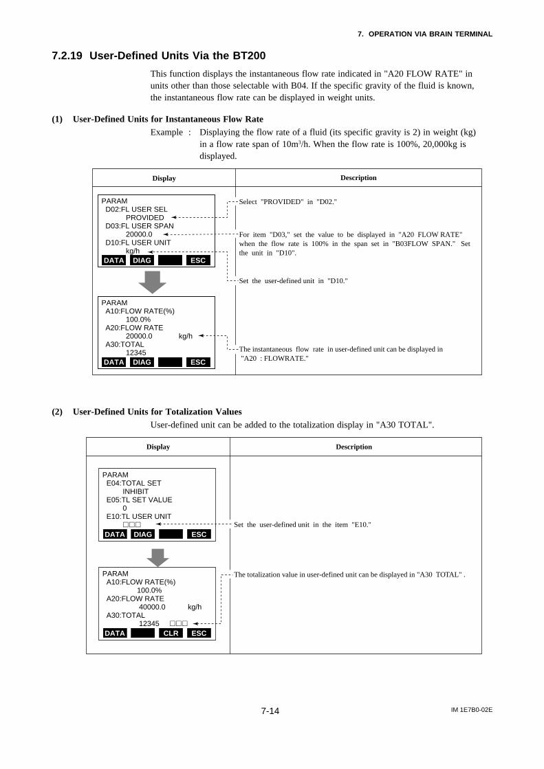
7. OPERATION VIA BRAIN TERMINAL
IM 1E7B0-02E7-14
7.2.19 User-Defined Units Via the BT200
This function displays the instantaneous flow rate indicated in "A20 FLOW RATE" inunits other than those selectable with B04. If the specific gravity of the fluid is known,the instantaneous flow rate can be displayed in weight units.
(1) User-Defined Units for Instantaneous Flow RateExample : Displaying the flow rate of a fluid (its specific gravity is 2) in weight (kg)
in a flow rate span of 10m3/h. When the flow rate is 100%, 20,000kg isdisplayed.
Display Description
PARAM D02:FL USER SEL PROVIDED D03:FL USER SPAN 20000.0 D10:FL USER UNIT kg/hDATA ESCDIAGDATA ESCDIAG
PARAM A10:FLOW RATE(%) 100.0% A20:FLOW RATE 20000.0 kg/h A30:TOTAL 12345DATA ESCDIAGDATA ESCDIAG
Select "PROVIDED" in "D02."
For item "D03," set the value to be displayed in "A20 FLOW RATE" when the flow rate is 100% in the span set in "B03FLOW SPAN." Set the unit in "D10".
Set the user-defined unit in "D10."
The instantaneous flow rate in user-defined unit can be displayed in "A20 : FLOWRATE."
(2) User-Defined Units for Totalization ValuesUser-defined unit can be added to the totalization display in "A30 TOTAL".
Display Description
Set the user-defined unit in the item "E10."
The totalization value in user-defined unit can be displayed in "A30 TOTAL" .
PARAM E04:TOTAL SET INHIBIT E05:TL SET VALUE 0 E10:TL USER UNIT
ESCDIAG
DIAG
DATA
PARAM A10:FLOW RATE(%) 100.0% A20:FLOW RATE 40000.0 kg/h A30:TOTAL 12345
ESCCLRDATA

7. OPERATION VIA BRAIN TERMINAL
IM 1E7B0-02E7-15
7.2.20 Other Important Points to Note
(1) The automatic power-off function turns the terminal off automatically if no key ispressed for about 5 minutes or more. However, this function does not operate whenthe terminal is displaying the variables in (2) below.
(2) When A10 FLOW RATE (%) or A20 FLOW RATE is displayed, data are updatedevery 5 seconds.
(3) UPLD is used when the parameters of one ADMAG AE are copied to the BT andDNLD is used when the parameters copied to the BT are copied to another ADMAGAE. (For details, see the "BT200 Instruction Manual " (IM 1C0A11-01E).Parameters that can be copied include span and pulse factor parameters such as thefollowing:
B02 DAMPING, B03 FLOW SPAN, B04 FLOW UNIT, B05 TIME UNITB06 SIZE UNIT, B07 NOMINAL SIZE, B10 OUTPUT FUNC, B11 4-20 ALM OUTD01 DISP SELECT, D02 FL USER SEL, D03 FL USER SPAN, D10 FLUSERUNIT, E01 TOTAL UNIT, E02 TOTAL SCALE, E03 TOTAL LOWCUT,E04 TOTAL SET, E05 TL SET VALUE, E10 TL USER UNIT, F01 PULSESELECT, F02 PULSE SCALE, F03 PULSE LOW CUT, F04 PULSE WIDTH,G01 4-20 LOW CUT, G02 4-20 LOW LMT, G03 4-20 H LMT.

IM 1E7B0-02E8-1
8. ACTUAL OPERATION
8. ACTUAL OPERATION
After you have installed the flowtube into the processpiping, wired the input / output terminals, set up therequired parameters, and performed the pre-operationzero adjustment, the magnetic flowmeter should outputan accurate flow signal from its terminals as soon asthe measured liquid begins to flow.
This section describes procedures of zero adjustmentand alarms countermeasure.
8.1 Pre-Operation ZeroAdjustment
In the magnetic flowmeter, zero adjustment is requiredbefore beginning operation in order to obtain a 4 to20mA signal that is accurately proportional to the flow.
This section describes two procedures for performingzero adjust : one using the switches on the converterpanel and the other using the BT200. Use eithermethod.
Zero adjustment is made to set the instrument to 0%(4mA) when the flow rate is 0.
The flow tube must be filled with fluid and let it standuntil all motion has ceased.
IMPORTANT
•Zero adjustment should be done only when thefluid is filled in the flow tube and the fluid velocityis completely zero by closing the valve.•Zero adjustment should be done prior to theother operation. For 30 seconds during the zeroadjustment, any setting cannot be accepted.
8.1.1 Zero Adjustment Using DataSetting Keys
The following two procedures can be used to performzero adjustment with the data setting keys.
(1) Hold Down the INC Key for Two Seconds in FlowRate Data Display Mode.
Display Description
Code Content
Call up the setting mode and set "01" in "C1".(zero adjustment enable / inhibit)
Hold down the INC key for two seconds in flow rate data display mode.
The display panel shows "-ZEro-".After about 30 seconds, the zero correction is displayed. Then the meter returns to data display mode.
00
01
INHIBIT
ENABLE
SET SHIFT INC
Default : 01
%
2 seconds or longer
(2) Display "C2" and Press the SET key Twice.
Display Description
Code Content
Call up the setting mode and set "01" in "C1"(zero adjustment enable/inhibit).
Call up "C2" and press the SET key twice(as for data entry).
The display panel shows "-ZEro-".After about 32 seconds, the zero correction is displayed.Then the meter returns to data display mode.
00
01
INHIBIT
ENABLE
SET SHIFT INC
Twice
32 secondslater
(Displays the zero correction)

IM 1E7B0-02E8-2
8. ACTUAL OPERATION
8.1.2 Zero Adjustment Via the BT200
CLR
DATA
DATA
Display Description
Call up the menu screen and select "C:ADJUST"
Press the ENTER key to call the screen displaying the parameter sub items. Select C02:MAGFLOW ZERO
Pressing the ENTER key causes the data setup screen to be displayed. If the security screen is displayed, enter the security code.*
While "C02:MAGFLOW ZERO" is displayed, press the ENTER key once, then wait a few seconds and press again. "AUTO ZERO" is now displayed
After about 30 seconds, press the "F4" of the Function key causes the Menu screen to be displayed. The zero correction is displayed. Then the meter returns to data display mode.
MENU A:DISPLAY B:SET C:ADJUST D:DISP SEL E:TOTAL SET F:PULSE SET
ESCSET ADJ
DIAG
HOME
PARAM C01:ZERO TUNING ENABLE C02:MAGFLOW ZERO 0 .05 C60:SELF CHECK GOOD
ESCDIAG
CLR
DATA
SETC02:MAGFLOW ZERO 0.05 + 00.05
ESCDIAG
DIAG
SETC02:MAGFLOW ZERO AUTOZERO
OKNOFEED
DIAG
PARAM C01:ZERO TUNING ENABLE C02:MAGFLOW ZERO 0 .02 C60:SELF CHECK GOOD
ESCDATA
*For entry of the security code,see IM 1C0A11-01E

IM 1E7B0-02E8-3
8. ACTUAL OPERATION
8.2 Self-diagnosticsFunctions
• The self-diagnostics function displays instrumentinternal errors, input/output signal abnormalities,setting errors, and other problems.
• When an alarm occurs, an alarm number announcingthat an error has occurred is superimposed on thenormal data display. However, alarms are onlydisplayed during normal flow rate data display modeand when parameter numbers are changed in thesetting mode. (Alarms are not displayed when dataitems are being changed.)
• When the BT200 is used, alarms are displayed in theA60 to N60 SELF CHECK parameter.
8.2.1 Display and Output Statusduring Alarm Occurrence
• If an error occurs, the panel display LED flashesand an alarm number is superimposed on the normaldisplay.During this time the current output is fixed to 2.4mAor less, 4mA, HOLD or 21.6mA or more, as selectedin 4-20 ALM OUT (out-put current during alarm).
• An alarm (status contact output) is output for any ofthe errors indicated in the table at right.
LEDContact output
Currentoutput
Totaliza-tion pulse
Display
AE Display on BT
00
01
02
03
04
05
06
07
08
09
10
11
12
13
14
15
16
17
18
19
20
21
GOOD
ERROR
µ P FAULT
EEPROM FAULT
A/D(H) FAULT
A/D(L) FAULT
SIGNAL OVERFLOW
COIL OPEN
VEL. SAPN>10m/s
VEL. SPAN<0.3m/s
P.SPAN>1000p/s
P.SPAN>500m/s
P.SPAN>25p/s
P.SPAN>15p/s
P.SPAN>10p/s
P.SPAN>5p/s
P.SPAN<0.0001p/s
T.SPAN>1000p/s
T.SPAN<0.0001p/s
4-20 LMT ERROR
EMPTY PIPE
MULTI RANGE ERROR
OFF ON Normally Normally
Flash-ing
OFF
Note: As selected in 4-20 ALM OUT(output current during alarm)
Fixed(See
note.)
Stop
8.2.2 Error Description and Countermeasures
02
03
04
05
08
09
16
17
18
19
21
06
µ P FAULT
EEPROM FAULT
A/D(H) FAULT
A/D(L) FAULT
VEL. SAPN>10m/s
VEL. SAPN<0.3m/s
P.SPAN<0.0001p/s
T.SPAN>1000p/s
T.SPAN<0.0001p/s
4-20 LMT ERROR
MULTI RANGE ERROR
Microprocessor error
EEPROM error
A/D converter (high frequency side) error
A/D converter (low frequency side) error
Setting for span flow velocity exceeds 11 m/s
Setting for span flow velocity is 0.2m/s or below
Pulse output rate exceeds 1100 p/s, at 50%DUTY Pulse output rate exceeds 1000 p/s, at 0.5 ms pulse width
Pulse output rate exceeds 500 p/s at 1 ms pulse width
Pulse output rate exceeds 25 p/s at 20 ms pulse width
Pulse output rate exceeds 15 p/s at 33 ms pulse width
Pulse output rate exceeds 10 p/s at 50 ms pulse width
Pulse output rate exceeds 5 p/s at 100 ms pulse width
Pulse output rate is 0.00005 p/s or below
Totalization rate exceeds 1100 p/s
Totalization rate is 0.00005 p/s or less
Analog low limit > Analog high limit
Pipe is not filled with fluid or insulating material attached to electrode.
In Auto 2 range, 1st range>2nd range
SIGNAL OVERFLOW
AE Display on BT Error Contents Countermeasures
Check for the following :-Mixup of the signal, power supply, execution, and other cable.-Stray electorical currents in the measured liquid.-Improper grounding
Contact the nearest Yokogawaoffice, or service center
Contact the nearest Yokogawaoffice, or service center
Change setting
Fill the flow tube with fluid or clean the flow tube insideChange setting
Excessive input signal
07 COIL OPEN Flow Tube coil open-circuit
P.SPAN>1000p/s10
11 P.SPAN>500p/s
12 P.SPAN>25p/s
13 P.SPAN>15p/s
14 P.SPAN>10p/s
15 P.SPAN>5p/s
20 EMPTY PIPE

IM 1E7B0-02E9-1
9. MAINTENANCE
9. MAINTENANCE
9.1 Loop Test (TestOutput)
This function enables you to set up any desired value,and to output it from the converter. Since this functioncorreponds to flow rate totalization display and pulseoutput, this makes it possible to check operation ofindividual functions.
The test functions of status output are also provided.
IMPORTANT
•Test outputs take priority of the flow signal. Donot forget to return to the normal operationmode after the loop test.•In case "BI DIRECTION" is set at OUTPUTFUNCTION (Parameter No. b10), the settingrange is available -108 to +108. Please set theloop test value in +/- percentage based on thelarger flow span within forward and reverse flowspan.•In case "AUTO 2 RANGES" is set at OUTPUTFUNCTION (Parameter No.b10), the loop testsetting value should be set in percentage basedon the second range.
9.1.1 Settings for Test Output UsingData Setting Keys
(1) Current Output (Corresponding to Flow Rate,Pulse and Totalization Display)
Display Description
Call up the setting mode and display "H1" (test mode ) and set "01".
Display "H2" and set the value in % ofmaximum span.(The figure shows a 100% setting.)
Code Content
0001
Normal operationTest output
Setting range : -8(-108) to 108%
*These functions must be returned to their originalstatus during flow rate measurements.
(2) Status Output
Display Description
Call up the setting mode and display "H1"(test mode ) and set "01".
Select the mode of status to be output in "H3".
Code Content
0001
Normal operationTest output
Code Content
000102
Normal operationTransistor contact (ON)Transistor contact (OFF)
*These functions must be returned to their originalstatus during flow rate measurements.
9.1.2 Setting for Test Output Via theBT200
(1) Current Output (Corresponding to Flow Rate, Pulseand Totalization Display)
Display Description
PARAM H01:TEST MODE TEST H02:OUTPUT VALUE 100 % H03:STATUS OUT NORMALDATA ESCDIAG
Select Test mode in parameter number "H01".
Display "H02:OUTPUT VALUE" and setthe value in % of maximum span. (The figure shows a 100% setting.)
Code
NORMALTEST
Normal operationTest output
Description
*These functions must be returned to their originalstatus during flow rate measurements.
(2) Status Output
Display Description
PARAM H01:TEST MODE TEST H02:OUTPUT VALUE 100 % H03:STATUS OUT NORMALDATA ESCDIAG
Call up the setting mode and display "H1"
Select the mode of status to be output in "H03".
Code
NORMALTEST
Normal operationTest output
Content
Code Content
NORMALCLOSED(ON)OPEN(OFF)
Normal operationTrarsistor contact (ON)Trarsistor contact (OFF)
(test mode) and set "01".
*These functions must be returned to their originalstatus during flow rate measurements.

IM 1E7B0-02E9-2
9. MAINTENANCE
9.2 Fuse Replacement
WARNING
This instrument must be installed by expertengineer or skilled personnel. Fuse replacementis not permitted for operators.
The fuse holder is located under the display which hasto be removed to allow fuse replacement. A spare fuseis taped to the cover of the converter.
Fuse holder
CAUTION
Before replacing the fuse, make sure to turn OFF the power supply and disconnect the power source.Use only specified fuses which should be obtained from your nearest Sales & Service Office. The use ofother fuses might cause fire. After replacing the fuse, confirm that the connecter of the display board hasnot loosened.
9.3 Trouble ShootingAlthough magnetic flowmeters rarely require maintenance, failures occur when the instrument is not operatingcorrectly. Since a failure is located by troubleshooting the receiving instrument information. This information will bedescribed below.
(1) No Indication
START
Check the code indication(see Page 7-5) and examinedepending on the contents.
Contact youragency orthe nearestsales office.
Check that the flow tube isfilled with the liquid.
Change piping ormouting so that theflow tube is full ofliquid.
Inspect inside of tube byremoving.
Remove foreign matter.Contact your agency or the nearest sales office.
Execute either of the following.a, Install flow tube to make
arrow agree with flow direction.
b, Change setting in 14 or B14 "FLOW DIR"
NO
NO
NO
NO
NO
NO
YES
YES
YES
YES
YES
YES
YES
NO
Examine the converter display or LED flashing wheather an error is displayed
Is an error displayed?
Is other display appearing?
Is the fuse blown?
Does the display reappearby replacing the fuse?
YES
Replacingthe fuse.
Does the arrow on flow tube agree with the flow direction?
Is the flow tube full of the liquid?
Is foreign matter sticking to the wall?

IM 1E7B0-02E9-3
9. MAINTENANCE
(2) Unstable Zero
Insulation deterioration is suspected.Examine the meter.
Examine whether or not theflow tube is filled with liquidand the liquid does not containbubbles.
Examine whether or not the valves leak.
Recheck liquid property.
Replace valves.
Completely grounding (grounding resistance must be 100 Ω or less.)
Sufficiency shield the meter.Locate the meter as far as possible from this equipment.
NO
NO
YES
NO
YES
NO
NO
NO
YES
NO
YES
YES
YES
YES
It is convenient to provide a gas vent hole on the downstream side of the flow tube to check for bubbles.
In particular, be careful for horizontal mouting. Change mounting position or change to vertical mounting with upward flow so that the flow tube is completely filled with liquid.
Mount a deforming device onthe upstream side of the flow tube
• Confirm the flow tube grounding.• Confirm whether or not the
grounding wire is disconnected from the earth flange.
a, Insure that the liquid conductivity does not change beyond fluid limits.
b, Do not use the meter with liquid conductivity below 5
µs / cm.c, Decrease flow velocity near the conductivity low limit as
much as possible
• Remove dirt and scale on and near electrodes. • Change to vertical meter
mounting.
START
Is the flowmeter located nearmortors, transformers,
or other electric equipment?
NO
YES
Are valves leaking?
Is the flow tube filled with liquid completely?
Are bubbles contained in the liquid?
Is grounding complete?
Is the liquid likely to cause deposit?
• Does the fluid conductivity vary
or is it easy to change?• Is Liquid conductivity sometimes
below 5µs/cm?
*
*
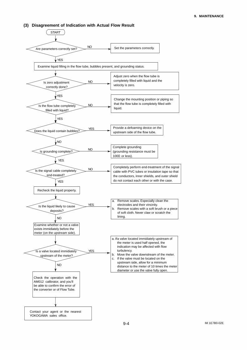
IM 1E7B0-02E9-4
9. MAINTENANCE
(3) Disagreement of Indication with Actual Flow Result
NO
NO
YES
NO
NO
YES
YES
YES
NO
YES
YES
NO
YES
Examine liquid filling in the flow tube, bubbles present, and grounding status.
Adjust zero when the flow tube is completely filled with liquid and the velocity is zero.
Recheck the liquid property.
Change the mounting position or piping so that the flow tube is completely filled with liquid.
Provide a defoaming device on the upstream side of the flow tube.
Complete grounding (grounding resistance must be 100Ω or less).
Completely perform end-treatment of the signal cable with PVC tubes or insulation tape so that the conductors, inner shields, and outer shield do not contact each other or with the case.
a. Remove scales. Especially clean the electrodes and their vincinity.
b. Remove scales with a soft brush or a piece of soft cloth. Never claw or scratch the lining.
NO
YES
a. If a valve located immidiately upstream of the meter is used half opened, the indication may be affected with flow turbulency.
b. Move the valve downstream of the meter.c. If the valve must be located on the
upstream side, allow for a minimum distance to the meter of 10 times the meter diameter or use the valve fully open.
Examine whether or not a valve exists immidiately before the meter (on the upstream side).
NO Set the parameters correctly.Are parameters correctly set?
Is zero adjustment correctly done?
Is the flow tube completelyfilled with liquid?
Does the liquid contain bubbles?
Is grounding complete?
Is the signal cable completelyend-treated?
Is the liquid likely to causedeposits?
Is a valve located immidiately upstream of the meter?
START
Contact your agent or the nearest YOKOGAWA sales office.
Check the operation with the AM012 calibrator, and you'll be able to confirm the error ofthe converter or of Flow Tube.

10. OUTLINE
IM 1E7B0-02E10-1
STANDARD SPECIFICATIONS
Note 1: For models with no indicator, a hand-heldterminal is necessary to set parameters.
Note 2: Pulse output, status output and alarm output usecommon terminals, therefore, these functions arenot available at the same time.
Note 3: Please refer to GS 01E07F01-00E for Fieldbuscommunication type(/FB).
Excitation method: Dual frequency excitationOutput Signal(Note 3):
Current Output: 4 to 20 mA DC (Load resistance 750Ωmaximum).
Transistor Contact Output(Open-collector):Pulse, alarm or status output selected byparameter setting. Contact rating: 30 V DC(OFF), 200 mA (ON).
Communication (option)(Note 3):BRAIN or HART (Superimposed on the 4 to 20 mA DCsignal)Load Resistance: (including cable resistance)
BRAIN: 250 to 600ΩHART: 230 to 600Ω, depending on q’ty of field
devices connected to the loop (multidropmode)
Load Capacitance: 0.22 µF maximumLoad Inductance: 3.3 mH maximumDistance from Power Line:
15 cm(0.6 ft) or more (Parallel wiring shouldbe avoided.)
Input Impedance of Receiver Connected to the Receiv-ing Resistance: 10kΩ or larger (at 2.4 kHz)
Maximum Cable Length:2 km (6500 ft) (when polyethylene-insulatedPVC-sheathed control cables (CEV cables)are used)
Note: HART is a registered trademark of the HARTCommunication Foundation.
Instantaneous Flow Rate Display Function:Flow rate can be displayed either in engineer-ing units or in percent of span.(for models with indicator)
Totalizer Display Function:Totalized volume in any engineering unit canbe displayed by setting a totalizing factor. (formodels with indicator)
Damping Time Constant(Note 1):Settable from 0.1 second to 200 seconds(63% response time).
Span Setting Function(Note 1):Volumetric flow setting is available by settingvolume unit, time unit, flow rate value andflow tube size.
Volume Unit: gallon(US), m3, l (litre), cm3,barrel(=158.987L)
Velocity Unit: ft, mTime Unit: sec., min., hour, dayFlow Tube Size: inch, mm
Pulse Output Function(Note 2), (Note 3):Scaled pulse can be output by setting a pulsefactor.
Pulse Width: Duty 50% or fixed pulse width (0.5, 1, 20,33, 50, or 100 ms) - user selectable.
10. OUTLINEOutput Rate: 0.0001 to 1000pps (when pulse output
function is selected.)Status Output Function(Note 2), (Note 3):
One of the following is selected by parametersetting.
• Auto 2 Ranges Status Output:Indicates the selected range for automaticdual range function.
• Forward and Reverse Status Output:Indicates the flow direction for forward andreverse flow measurement mode.
• Totalization Status Output:Indicates that the internal totalized valueexceeds the set value.
• Low Limit Alarm:Indicates that flow rate is under the low limitset value.
Alarm Output Function(Note 2), (Note 3):Indcates that an alarm occurs(Normal Close Fixed).
Self Diagnostics Function(Note 1):Converter failure, flow tube failure, erroneoussetting, etc. can be diagnosed and displayed.
Data Security During Power Failure:Data storage by EEPROM - no back-upbattery required.
Electrical Connection:ANSI 1/2NPT female, DIN Pg13.5 female,ISO M20×1.5 female, JIS G1/2 female.
Terminal Connection: M4 size screw terminal.Case Material: Aluminum alloy.Coating: Polyurethane corrosion-resistant coating.
Cover; Deep sea moss green (Munsell0.6GY3.1/2.0)Case; Frosty white (Munsell 2.5Y8.4/1.2)
Degrees of Protection: IP67, NEMA 4X, JIS C0920water tight protection
Size:• General Purpose Type
Size in mm(inch)
Lining PFA Ceramic Polyurethane
T01.EPS
2.5(0.1), 5(0.2), 10(0.4), 15(0.5), 25(1), 40(1.5), 50(2), 80(3), 100(4), 150(6), 200(8)
25(1), 40(1.5), 50(2), 80(3), 100(4), 150(6), 200(8), 250(10), 300(12), 350(14), 400(16)
2.5(0.1), 5(0.2), 10(0.4), 15(0.5), 25(1), 40(1.5), 50(2), 65(2.5), 80(3), 100(4), 125(5), 150(6),200(8), 250(10), 300(12), 350(14),400(16)
• Explosion Proof Type
Size in mm(inch)
Lining PFA Ceramic
T02.EPS
2.5(0.1), 5(0.2), 10(0.4), 15(0.5), 25(1), 40(1.5), 50(2), 65(2.5), 80(3), 100(4), 125(5), 150(6), 200(8), 250(10)*, 300(12)*, 350(14)*,
2.5(0.1), 5(0.2), 10(0.4), 15(0.5), 25(1), 40(1.5), 50(2), 80(3), 100(4), 150(6), 200(8)
400(16)*
*250 to 400mm with flange connection are only for CENELEC ATEXor SAA.
250 and 300mm with wafer connection are only for general purpose use.*65 and 125mm are only for CENELEC ATEX.

10. OUTLINE
IM 1E7B0-02E10-2
• Sanitary Type
Size in mm(inch)
Lining PFA
T03.EPS
25(1), 40(1.5), 50(2), 65(2.5), 80(3), 100(4)
* 15 and 125mm flow tubes are available on request.Coating:
Body:Size 2.5 to 100 mm(0.1 to 4 in.):
No coating (Stainless steel surface)Size 125 to 400 mm(5 to 16 in.):
Polyurethane corrosion-resistant coating.Frosty white (Munsell 2.5Y8.4/1.2)
Flow Tube Material:Size 2.5 to 15 mm(0.1 to 0.5 in.)
Housing: Stainless steel (SCS11)Mini-flange for wafer conn.: Stainless steel (SUS430)Flange (15 mm(0.5 in.) only): Stainless steel
(SUS304)Pipe: Stainless steel (SCS13) or Alumina
ceramic (99.9%)Size 25 to 100 mm(1 to 4 in.)
Housing: Stainless steel (SUS304)Mini-flange for wafer conn.: Stainless steel (SUS430)Flange: Stainless steel (SUS304)Pipe: Stainless steel (SUS304)* or Alumina
ceramic (99.9%)Size 125 to 400 mm(5 to 16 in.)
Housing: Carbon steel (SS400)Flange: Carbon steel (SS400)Pipe: Stainless steel (SUS304)* or Alumina
ceramic (99.9% — Sizes 150 and 200mm only)
* For PFA or Polyurethane liningWetted Part Material:
Lining: Fluorocarbon PFA*, Alumina ceramic,Polyurethane.*PFA is FDA approved material.
Electrode: Stainless steel (SUS316L), Hastelloy C(equivalent to Hastelloy C-276), Titanium,Tantalum, Platinum-Iridium,Platinum-alumina cermet only for ceramiclining.* For sanitary type, SUS316L only
Earth Ring/Earth Electrode: Stainless steel (SUS316),Hastelloy C (equivalent to Hastelloy C-276), Titanium, PFA lining + Earthelectrodes (Tantalum, Platinum-Iridium)
Gasket: • VALQUA#7020 : Fluoro resin with filler(between flow tube body and earth ring; forceramic lining)
• VALQUA#4010 : Fluoro rubber, viton(between flow tube body and earth ring; foroptional code /FRG)
• Non-asbestos joint sheet sheathed withfluoro resin (between earth ring andprocess flange; for optional code /BCF or /BSF)
• Chloroprene rubber (between earth ringand process flange; for optional code /BCCor /BSC)
• EPDM, ethylene propylene rubber (forsanitary type)
* Other gaskets between flow tube body and earth ring;• VALQUA#7026 : corrosion resistance
gasket (Fluoro resin with carbon)• VALQUA#4010 (Mixing#RCD970) :Alkali
resistance gasket for PVC piping (Fluororubber)
• VALQUA#4010 (Mixing#RCD470) : Acidresistance gasket for PVC piping (Fluororubber)
* Contact Yokogawa office. (Refer to TI 1E6A0-06E.)Union Joint: Stainless steel (SUS316L) for ceramic
lining size 10 mm(0.4in.) or less.** Contact Yokogawa office if you use PVC union joints.Ferrule (for sanitary type): SCS13
Electrode Construction:• General Purpose/Ex-proof Type
PFA, Polyurethane Lining: External insertion type.Ceramic Lining: Integral type.
• Sanitary TypeInternal insertion type* Only PFA lining is available for sanitary type.
Note: Hastelloy is a registered trademark of HaynesInternational Inc.
STANDARD PERFORMANCEAccuracy:
PFA and Ceramic Lining
Size in mm(inch)
Span in m/s(ft/s)
Accuracy
2.5 to 15(0.1 to 0.5)
0.3 to 1(1 to 3)
1 to 10(3 to 33)
0.3 to 1(1 to 3)
1 to 10(3 to 33)
25 or larger(1)
0.5% of span
0.25% of span(at indications below 50% of span)
0.5% of rate (at indications 50% of span or more)
0.25% of span(at indications below 50% of span)
0.5% of rate (at indications 50% of span or more)
0.1% of span(at indications below 20% of span)
0.5% of rate (at indications 20% of span or more)
Size in mm(inch)
Span in m/s(ft/s)
Accuracy
0.3 to 1(1 to 3)
1 to 10(3 to 33)
25 or larger(1)
0.5% of span
0.25% of span(at indications below 50% of span)
0.5% of rate (at indications 50% of span or more)
Polyurethane Lining (except /FB)
PFA and Ceramic Lining (except /FB)
Size in mm(inch) Accuracy
2.5 to 15(0.1 to 0.5)
25 or larger(1)
1.5mm/s
0.5% of rate
0.75mm/s
0.5% of rate
T04.EPS
Polyurethane Lining (/FB)
PFA and Ceramic Lining (/FB)
Actual Flow Velocity in m/s(ft/s)
less than 0.3(1)
0.3(1) or more
less than 0.15(0.5)
0.15(0.5) or more
Size in mm(inch) Accuracy
25 or larger(1)
1.5mm/s
0.5% of rate
Actual Flow Velocity in m/s(ft/s)
less than 0.3(1)
0.3(1) or more

10. OUTLINE
IM 1E7B0-02E10-3
Repeatability: 0.1% of flowrate (minimum 1 mm/s)Maximum Power Consumption: 12.5WInsulation Resistance:
• 100MΩ between power terminals andground terminal at 500 V DC.
• 100MΩ between power terminals and eachoutput terminal at 500 V DC.
• 20MΩ between each output terminal andground terminal at 100V DC.
Withstand Voltage :1500 V AC between power terminals andground terminal for 1 minute.
CAUTION
When performing the Voltage Breakdown Test,Insulation Resistance Test or any unpowered electricaltest, wait 10 seconds after the power supply is turnedoff before removing the housing cover. Be sure toremove the Short Bar at terminal “G”. After testing,return the Short Bar to its correct position. Screwtightening torque should be 1.18N-m(0.88ft-lb)or more,because the G-terminal is thought as a protectivegrounding and should conform to the SafetyRequirements.
Safety Requirement Standards:IEC1010, EN61010
EMC Conformity Standards:EN61326EN61000-3-2, EN61000-3-3AS/NZS 2064
Grounding: 100Ω or less* In case of explosion proof type, the protective
grounding must be connected to a suitable ISgrounding system.
* In case of TIIS(JIS) Flameproof type, JIS Class C(10Ωor less) or JIS Class A(10Ω or less) grounding system.
NORMAL OPERATING CONDITIONSAmbient Temperature: –10 to 60˚C (14 to 140˚F)
Note: The minimum ambient temperature is –20°C isavailable only for these sizes 40 to 100 mm withSUS304 flange.
Ambient Humidity: 5 to 95%RH (no condensation)Power Supply Voltage: -A1; Range 80 to 264 V AC, 47
to 63Hz/100 to 130 VDC, -D1; Range 20.4 to 28.8 V DC(except /FB)
Supplied Power and Max. Cable Length for 24 V DCversion:
Allowable cable length m(ft)1000(3300)900(2970)800(2640)700(2310)600(1980)500(1650)400(1320)300(990)200(660)100(330)
020 22 24 26 28 (V)
Cable cross section area: 1.25 mm2
Cable cross section area: 2 mm2F01.EPS
Altitude at installation side: Max.2000m above sealevel
Installation category based on IEC1010: II(See Note)Pollution level based on IEC1010: 2(See Note)
Note: • The “Installation category“ implies the regulation forimpulse withstand voltage. It is also calledthe“Overvoltage category“. “II“ applies to electricalequipment.
• “Pollution level“describes the degree to which asolid, liquid or gas which deteriorates dielectricstrength is adhering. “2“ applies to normal indooratmosphere.
Fuse: 2A, 250V(Time - Lag type)Fluid Conductivity:
Size 15 to 200mm(0.5 to 8in.); 5µS/cm or largerSize 2.5 to 10mm(0.1 to 0.4in.); 20µS/cm or larger
*In case that size 250 or 300mm is used for high conductivityfluid (ex. caustic soda, seawater), please use the flange type.
Measurable Flow Rate Range:SI Units (Size: mm, Flowrate: m3/h)
SizeMin. Range
@0.3m/sMax. Range
@10m/s2.5 0.0054 0.17675 0.0213 0.7068
10 0.0849 2.827415 0.1909 6.36125 0.5302 17.67140 1.3572 45.2350 2.1206 70.6865 3.584 119.4580 5.429 180.95
100 8.483 282.74125 13.254 441.7150 19.086 636.1200 33.93 1,131250 53.02 1,767.1300 76.35 2,544.6350 103.91 3,463400 135.72 4,523
T06.EPS
English Units (Size: inch, Flowrate: GPM)
SizeMin. Range
@1.0ft/sMax. Range
@33ft/s0.1 0.0241 0.80310.2 0.0964 3.2120.4 0.3856 12.850 0.5 0.6024 20.0781 2.4095 80.311.5 5.422 180.70 2 9.638 321.22.5 15.06 501.93 21.685 722.84 38.56 1,285.05 60.24 2007.86 86.74 2,891.3 8 154.21 5,140
10 240.95 8,03112 347.0 11,56514 472.3 15,74116 616.9 20,560
T07.EPS
Fluid Temperature and Pressure:General Purpose /Explosion proof

10. OUTLINE
IM 1E7B0-02E10-4
PressureMPakgf/cm2psi
PressureMPakgf/cm2psi
440570
220285
-0.1-114.2
Ceramic 2.5 to 50 mm(0.1 to 2 in.) (Integral type)Ceramic 80 to 200 mm(3 to 8 in.) (Integral type)
-10(14)
0(32)
Temperature °C(°F)
Temperature °C(°F)
F02.EPS
120(248)
PFA (Integral; 50 mm or smaller)PFA (Integral type; 65 mm or larger)Polyurethane (50 mm or smaller)Polyurethane (80 mm or larger)
1
-10(14)
0(32)
40(104)
80(175)
120(248)
220285110142
-0.1-114.2
440570
Note 1: Those limits show maximum allowable fluidpressure for Flow Tube itself. Further fluid pressureshould also be limited according to processconnection.
Note 2: For Explosion proof type, maximum fluid pressureshould be 2MPa or lower (for 350 and 400 mm, 1MPa or lower) except CENELEC ATEX explosionproof version, and for fluid temperature refer todescriptions of “HAZARDOUS AREA CLASSIFICA-TION”.
PressureMPakgf/cm2psi
11014.3
-0.1-114.2-10(14)
Temperature °C(°F)F02-2.EPS
120(248)
Sanitary
PFA Integral type
Reasonable Figures for Thermal Shock of CeramicLining:
F03.EPS
Size 2.5 to 25 mm(0.1 to 1 in.)∆T°C(°F)
120(216)
100(180)
60(108)
Increase
Decrease
1(3) 5(15) 10(30)Flow Velocity m/s(ft/s)
Size 40 and 50 mm(1.5 and 2 in.)∆T°C(°F)
90(162)
50(90)
100(180)
30(54)
Increase
Decrease
1(3) 5(15) 10(30)Flow Velocity m/s(ft/s)
Size 80 to 200 mm(3 to 8 in.)∆T°C(°F)
50(90)
70(126)
30(54)
Increase
Decrease
1(3) 5(15) 10(30)Flow Velocity m/s(ft/s)
TERMINAL CONNECTION
Terminal Symbols Description
P+P–I+I–L/+N/–
Current output 4 to 20 mA DC
Power supply
Protective grounding
Pulse, alarm or status output
Terminal Symbols Description
P+P–I+I–L/+N/–
Fieldbus communication signal
Power supply
Protective grounding
Not used
T08.EPS
For Fieldbus Communication Type

10. OUTLINE
IM 1E7B0-02E10-5
SIZING DATA
15 25 6540 50 80 100
125
150
200
250
300
350Size: mm
400
Flow velocity(m/s)
0.5
1.0
5.0
10.0
0.3
Flow velocity(ft/s)
Flowrate (GPM)
33
5.0
1.0
10
2.0
1
SI Units
105
1 1,000100100.10.010.005
10,0001.0 1,00010010
Size (inch)
0.10.01
0.5 21.5 2.51 3 4 5 6 12108 14160.40.20.1
English Units
Flowrate (m3/h)
Size: inch2.
5
F29.EPS* Measurable flow velocity is from 0 m/s.

10. OUTLINE
IM 1E7B0-02E10-6
MODEL AND SUFFIX CODEGeneral Purpose/Explosion Proof, Integral Type AE100/200 series
AE102AE105AE110AE115AE202AE204AE205AE206AE208AE210AE212AE215AE220
Lining
A U C A C
Size 80 mm(3in.) or larger
Note 1Note 1Note 1Note 1
Size 150/200mm (6/8in.)onlyNote 2
––
––
–––
–
––––
–
–
––
–
–
–––
–––––
–
–––
–
–
––
––
––––––––
––
–––
–
–
–
–
––
–––
–
–
–
–
–
–
––
––––––––
––
–––
–
Suffix CodeModel Description
Use
MG SC
: Available –: Not available
Use MGMNSC
Lining
Process Connection(Note 3)
Electrode Material
Earth Ring/Earth Electrode Material
Electrical Connection
Power Supply
Indicator
Optional CodeT11.EPS
. . . . . . . . . . . . . . . . . . . . . . . . . . . . . . . .
. . . . . . . . . . . . . . . . . . . . . . . . . . . . . . . .
. . . . . . . . . . . . . . . . . . . . . . . . . . . . . . . .
. . . . . . . . . . . . . . . . . . . . . . . . . . . . . . . .
. . . . . . . . . . . . . . . . . . . . . . . . . . . . . . . .
. . . . . . . . . . . . . . . . . . . . . . . . . . . . . . . .
. . . . . . . . . . . . . . . . . . . . . . . . . . . . . . . .
. . . . . . . . . . . . . . . . . . . . . . . . . . . . . . . .
. . . . . . . . . . . . . . . . . . . . . . . . . . . . . . . .
. . . . . . . . . . . . . . . . . . . . . . . . . . . . . . . .
. . . . . . . . . . . . . . . . . . . . . . . . . . . . . . . .
. . . . . . . . . . . . . . . . . . . . . . . . . . . . . . . .
. . . . . . . . . . . . . . . . . . . . . . . . . . . . . . . .
Ceramic lining, size 2.5/ 5/10mm only
Note 7
DH DV N
MN
A C
–
–
––
––
–
–
–––
–
–––
–
–
–
––
––
–
––––––––
––
–––
–––
–
Note 4Note 5
Note 1: Process connection for size 2.5 to 10mm(0.1 to 0.4in.), wafer type is equal to one for 15mm(0.5in.). Provide 15mm process flanges for these flow tubes.
Note 2: Select PN16 when requirement of PN10 for sizes 80mm(3in.) to 150mm(6in) because of same mating dimensions. Not available with 65, 125mm.Note 3: Flange type is available for size 15mm or larger, PFA or Polyurethane lining.Note 4: Select ANSI 1/2NPT female electrical connection(code A) in case of requirement of FM/CSA explosion proof type.
For CENELEC ATEX explosion proof type, select ANSI 1/2NPT (code A) or ISO M201.5(code M) electrical connection.Note 5: Select JIS G1/2 female electrical connection (code J) and optional code /JF3 with /G11, /G12 in case of requirement
of TIIS(JIS) Flameproof type.Note 6: Platinum-iridium and Tantalum earth electrodes are not available with 65, 125mm and ceramics 150, 200mm.Note 7: Select “PN40” when requirement of PN10, PN16, PN25 for sizes 50mm or less wafer or flange process connection because
of same mating dimension.“PN40” is available for CENELEC ATEX, but not available for FM, CSA, or SAA ex-proof version.
Refer to "Optional Specifications."
Not available with 65/125mm
Not available with 65/125mm
Not available with 65/125mm
Not available with 65/125mm
Note 6
Note 6
Must for ceramic, 2.5/5/10mm
Size 80/100/150/200mm only
Not available with 65/125mm
Not available with 65/125mm
Note 7
. . . . . . . . . . . . . . . . . . . . . . . . . . . . . . . .
. . . . . . . . . . . . . . . . . . . . . . . . . . . . . . . .
. . . . . . . . . . . . . . . . . . . . . . . . . . . . . . . .
-A . . . . . . . . . . . . . . . . . . . . . . . . . .
-U . . . . . . . . . . . . . . . . . . . . . . . . . .
-C . . . . . . . . . . . . . . . . . . . . . . . . . .
K1 . . . . . . . . . . . . . . . . . . . . . .K2 . . . . . . . . . . . . . . . . . . . . . .B1 . . . . . . . . . . . . . . . . . . . . . .B2 . . . . . . . . . . . . . . . . . . . . . .E2 . . . . . . . . . . . . . . . . . . . . . .E4 . . . . . . . . . . . . . . . . . . . . . .H1 . . . . . . . . . . . . . . . . . . . . . .J1 . . . . . . . . . . . . . . . . . . . . . .J2 . . . . . . . . . . . . . . . . . . . . . .A1 . . . . . . . . . . . . . . . . . . . . . .A2 . . . . . . . . . . . . . . . . . . . . . .D1 . . . . . . . . . . . . . . . . . . . . . .D2 . . . . . . . . . . . . . . . . . . . . . .D4 . . . . . . . . . . . . . . . . . . . . . .G1 . . . . . . . . . . . . . . . . . . . . . .U1 . . . . . . . . . . . . . . . . . . . . . .U2 . . . . . . . . . . . . . . . . . . . . . .U3 . . . . . . . . . . . . . . . . . . . . . .
-L . . . . . . . . . . . . . . . . . .-P . . . . . . . . . . . . . . . . . .-E . . . . . . . . . . . . . . . . . .-H . . . . . . . . . . . . . . . . . .-T . . . . . . . . . . . . . . . . . .-V . . . . . . . . . . . . . . . . . .
S . . . . . . . . . . . . . . .P . . . . . . . . . . . . . . .N . . . . . . . . . . . . . . .H . . . . . . . . . . . . . . .T . . . . . . . . . . . . . . .V . . . . . . . . . . . . . . .
J . . . . . . . . . . .A . . . . . . . . . . .D . . . . . . . . . . .M . . . . . . . . . . .
-A1 . . . . .-D1 . . . . .
DH . .
DV . .
N. . . .
/
Size 2.5 mm (0.1in.)Size 5 mm (0.2in.)Size 10 mm (0.4in.)Size 15 mm (0.5in.)Size 25 mm (1in.)Size 40 mm (1.5in.)Size 50 mm (2in.)Size 65 mm (2.5in.)Size 80 mm (3in.)Size 100 mm (4in.)Size 125 mm (5in.)Size 150 mm (6in.)Size 200 mm (8in.)
General purpose typeCENELEC,FM,CSA,SAA Ex-proofTIIS (JIS) Flameproof
Fluorocarbon PFAPolyurethane Ceramic
JIS 10K waferJIS 20K waferANSI 150 waferANSI 300 waferDIN PN10/16 waferDIN PN40 waferJIS F12(JIS75M) waferJIS 10K flangeJIS 20K flangeANSI 150 flangeANSI 300 flangeDIN PN10 flangeDIN PN16 flangeDIN PN40 flangeJIS F12(JIS75M) flangeUnion Joint (weld joint)Union Joint (R1/4 or R3/8)Union Joint (1/4NPT or 3/8NPT)
Stainless Steel (SUS316L)Platinum-iridiumPlatinum-alumina cermetHastelloy C276 equivalentTantalumTitanium
Stainless Steel (SUS316)Platinum-iridiumNoneHastelloy C276 equivalentTantalumTitanium
JIS G1/2 femaleANSI 1/2NPT femaleDIN Pg13.5 femaleISO M20×1.5 female
80 to 264 V AC/100 to 130 V DC20.4 to 28.8 V DC
7seg.LCD(Horizontal Mounting)7seg.LCD(Vertical Mounting)None
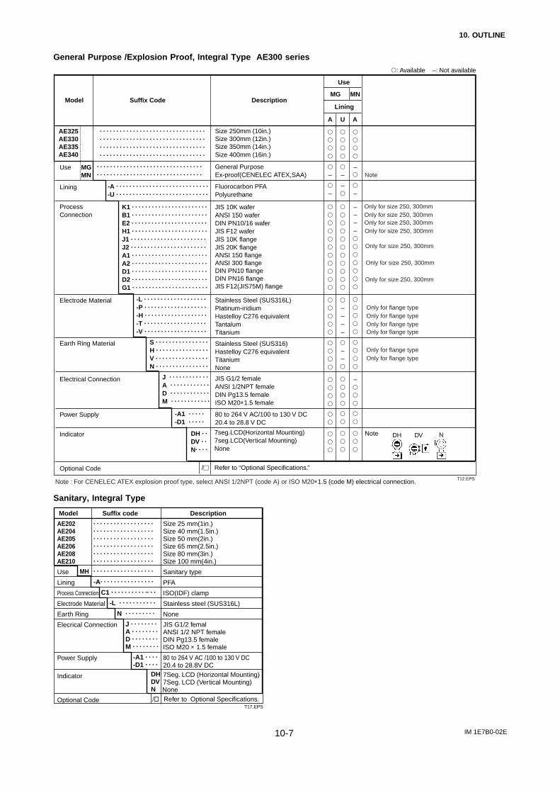
10. OUTLINE
IM 1E7B0-02E10-7
General Purpose /Explosion Proof, Integral Type AE300 series
AE325AE330AE335AE340
. . . . . . . . . . . . . . . . . . . . . . . . . . . . . . . .
. . . . . . . . . . . . . . . . . . . . . . . . . . . . . . . .
-A . . . . . . . . . . . . . . . . . . . . . . . . . . . .
-U . . . . . . . . . . . . . . . . . . . . . . . . . . . .
K1 . . . . . . . . . . . . . . . . . . . . . . .
B1 . . . . . . . . . . . . . . . . . . . . . . .
E2 . . . . . . . . . . . . . . . . . . . . . . .
H1 . . . . . . . . . . . . . . . . . . . . . . .
J1 . . . . . . . . . . . . . . . . . . . . . . .
J2 . . . . . . . . . . . . . . . . . . . . . . .
A1 . . . . . . . . . . . . . . . . . . . . . . .
A2 . . . . . . . . . . . . . . . . . . . . . . .
D1 . . . . . . . . . . . . . . . . . . . . . . .
D2 . . . . . . . . . . . . . . . . . . . . . . .
G1 . . . . . . . . . . . . . . . . . . . . . . .
-L . . . . . . . . . . . . . . . . . . .
-P . . . . . . . . . . . . . . . . . . .
-H . . . . . . . . . . . . . . . . . . .
-T . . . . . . . . . . . . . . . . . . .
-V . . . . . . . . . . . . . . . . . . .
S . . . . . . . . . . . . . . . .
H . . . . . . . . . . . . . . . .
V . . . . . . . . . . . . . . . .
N . . . . . . . . . . . . . . . .
J . . . . . . . . . . . .
A . . . . . . . . . . . .
D . . . . . . . . . . . .
M . . . . . . . . . . . .
-A1 . . . . .
-D1 . . . . .
DH . .
DV . .
N. . . .
/
Size 250mm (10in.)Size 300mm (12in.)Size 350mm (14in.)Size 400mm (16in.)
General PurposeEx-proof(CENELEC ATEX,SAA)
Fluorocarbon PFAPolyurethane
JIS 10K waferANSI 150 waferDIN PN10/16 waferJIS F12 waferJIS 10K flangeJIS 20K flangeANSI 150 flangeANSI 300 flangeDIN PN10 flangeDIN PN16 flangeJIS F12(JIS75M) flange
Stainless Steel (SUS316L)Platinum-iridiumHastelloy C276 equivalentTantalumTitanium
Stainless Steel (SUS316)Hastelloy C276 equivalentTitaniumNone
JIS G1/2 femaleANSI 1/2NPT femaleDIN Pg13.5 femaleISO M20×1.5 female
80 to 264 V AC/100 to 130 V DC20.4 to 28.8 V DC
Lining
A U A
–
–
–
–
––––
––
–
–
––––
–
Suffix CodeModel Description
Use
MG MN
: Available –: Not available
Use MGMN
Lining
Process Connection
Electrode Material
Earth Ring Material
Electrical Connection
Power Supply
Indicator
Optional Code
T12.EPS
. . . . . . . . . . . . . . . . . . . . . . . . . . . . . . . .
. . . . . . . . . . . . . . . . . . . . . . . . . . . . . . . .
. . . . . . . . . . . . . . . . . . . . . . . . . . . . . . . .
. . . . . . . . . . . . . . . . . . . . . . . . . . . . . . . .
Refer to “Optional Specifications.”
7seg.LCD(Horizontal Mounting)7seg.LCD(Vertical Mounting)None
Note DH DV N
Only for size 250, 300mmOnly for size 250, 300mm
Only for size 250, 300mmOnly for size 250, 300mm
Only for size 250, 300mm
Only for size 250, 300mm
Only for size 250, 300mm
Only for flange type
Only for flange type
Only for flange typeOnly for flange type
Only for flange typeOnly for flange type
Note
Note : For CENELEC ATEX explosion proof type, select ANSI 1/2NPT (code A) or ISO M20×1.5 (code M) electrical connection.
Sanitary, Integral Type
AE202AE204AE205AE206AE208AE210
Use
Lining
Process Connection
Electrode Material
Earth Ring
Elecrical Connection
Power Supply
Indicator
Optional Code Refer to Optional Specifications.None
. . . . . . . . . . . . . . . . . .
-A. . . . . . . . . . . . . . . .
C1 . . . . . . . . . . .. . .
-L . . . . . . . . . . .
N . . . . . . . . .
J . . . . . . . .A . . . . . . . .D . . . . . . . .M . . . . . . . .
-A1 . . . .-D1 . . . .
DHDVN
Model Suffix code Description
Size 25 mm(1in.)Size 40 mm(1.5in.)Size 50 mm(2in.)Size 65 mm(2.5in.)Size 80 mm(3in.)Size 100 mm(4in.)
Sanitary type
PFA
ISO(IDF) clamp
Stainless steel (SUS316L)
None
JIS G1/2 femalANSI 1/2 NPT femaleDIN Pg13.5 femaleISO M20 × 1.5 female
80 to 264 V AC /100 to 130 V DC20.4 to 28.8V DC7Seg. LCD (Horizontal Mounting)7Seg. LCD (Vertical Mounting)
. . . . . . . . . . . . . . . . . .
. . . . . . . . . . . . . . . . . .
. . . . . . . . . . . . . . . . . .
. . . . . . . . . . . . . . . . . .
. . . . . . . . . . . . . . . . . .
. . . . . . . . . . . . . . . . . .
T17.EPS
MH
/

10. OUTLINE
IM 1E7B0-02E10-8
Optional Specifications
Item Specification CodeSanitaryEx-proof
Applicable Model
General
AE***DHAE***MHAE***DNAE14AE***DGAE***MG AE14 AE***MNWaterproof glands are attached to all wiring ports. For JIS G1/2 only.
Waterproof glands (union joint) are attached to all wiring ports. For JIS G1/2 only.
Gaskets are attached between earth ring and flow tube. (Not available with 65, 125mm)
Eliminating DC Noise (Size 15mm(0.5in.) or larger: Conductivity 50S/cm or higher.)
Built-in Lightning Protector(Only for 24VDC version)
Digital Communication with BRAIN protocol
Digital Communication with HART protocol
Digital Communication with FOUNDATION Fieldbus protocol (except 24 VDC version)
PID control function and Link Master function
Coating is changed to epoxy coating.
Coating is changed to three-layer coating(Urethane coating on two-layer Epoxy coating)
Reproduced material certificate for pipe, electrode, earth ring, mini-flange and flange (depends on spec.).
Carbon steel bolts/nuts and chloroprene gaskets assembly for wafer type
Carbon steel bolts/nuts and non-asbestos PTFE-wrapped gaskets assembly for wafer type
wStainless steel bolts/nuts and chloroprene gaskets assembly for wafer type
Stainless steel bolts/nuts and non-asbestos PTFE-wrapped gaskets assembly for wafer type
Condensation proof for District Heating and Cooling use. Terminal box; urethane resin potting. Wired 30m signal cable at factory.
FM Explosion proof/FM Nonincendive
CENELEC ATEX Explosion proof
CSA Explosion proof/CSA Nonincendive
SAA Explosion proof
TIIS(JIS) Flameproof type
One Flameproof Packing Adapter and a blind plug are attached.(only for DC power supply)
Two Flameproof Packing Adapters are attached.(Not apply for one port wiring.)
Calibration Certificate for GOST (only for products produced at YMF)
In case of fluid temp. over 120°C (248°F), 160°C (320°F) max. (Not available with 65mm)
Mirror Finishing on the inside of ceramic tube (Rmax.<=1 micro-meter)
180deg. rotated converter for reversed flow direction
Degreased cleansing treatment
Degreased cleansing treatment; Packing with desiccant
Test pressure depends on process connection(Test duration 10 minutes) Test result is full in NOTE of QIC.
Level 2:Declaration and Calibration Equipment List
Level 3:Declaration and Primary Standard List
Level 4:Declaration and YOKOGAWA Measuring
Waterproof Gland
Waterproof Gland with Union Joint
Gaskets for PVC pipe
DC Noise Suppression
Lightning Protector
BRAIN Communication(Note 1)
HART Communication(Note 1)
FOUNDATION Fieldbus Communication (Note 1)
PID/LM function for FOUNDATION Fieldbus (Note 6)
Epoxy Coating
High Anti-corrosion Coating
Material Certificate(Note 2)
Bolt & Nut Assembly(Note 3 )
DHC use (for size 100 to 400mm)
FM Approval(Note 4)
CENELEC ATEX Certification (KEMA Approval)
CSA Certification(Note 4)
SAA CertificationTIIS(JIS) Flameproof(Note 4)(Note 5)
Flameproof Packing Adapterfor TIIS(JIS) Flameproof (Note 5)(Only for JIS G1/2 electrical connection)
GOST Certification
Silicon Rubber Gasket for sanitary type
Mirror Finished Ceramics
180deg. Rotated Converter
Oil-prohibited Use
Oil-prohibited Use with Dehydrating Treatment
Hydrostatics Test Certificate
Calibration Certificate
T19.EPSNote 1: Either BRAIN, HART, or FOUNDATION Fieldbus communication can be selected.Note 2: In case of requirement of EN10204 3.1B for Material Certificate, contact Yokogawa office.Note 3: It is available only for JIS 10K wafer, JIS 20K wafer or ANSI 150 wafer type, not available with 65, 125, 250 or 300mm.Note 4: It is available only for size 2.5 to 200mm(0.1 to 8 in). Note 5: Select optional code /JF3 with /G11 or /G12 in case of requirement of TIIS (former JIS) Flameproof type.
/G11 is selectable only for DC power supply and 4-conductor cable use.Note 6: Optional code /LC1 is a function for Fieldbus communication. Optional code /FB must be selected together with /LC1.Note 7: Ex-proof Fieldbus communication is available for CENELEC ATEX, FM and TIIS (former JIS) ex-proof version.
: Available –: Not available
AE***SC
–
–
–
–
–
–
–
–
–
–
–
–
–
–
–
–
–
–
–
–
–
–
–
–
–
–
–
–
–
–
–
–
–
–
–
–
–
–
–
–
–
–
–
–
–
–
–
–
–
–
–
–
–
–
–
–
–
–
–
(Note 5)
(Note 5)
(Note 5)
–
–
–
–
–
–
–
–
–
–
–
–
–
–
–
–
–
–
–
–
–
–
–
–
–
–
–
–
–
–
–
–
–
–
–
–
–
–
–
–
–
–
–
–
–
–
–
–
–
–
–
–
–
–
–
–
–
–
–
–
–
–
–
–
–
–
–
–
–
–
–
–
–
–
–
–
–
–
/ECG
/ECU
/FRG
/ELC
/A
/BR
/HART
/FB
/LC1
/EPF
/X2
/M01
/BCC
/BCF
/BSC
/BSF
/DHC
/FF1/FN1
/KF2
/CF1/CN1
/SF1
/JF3
/G11
/G12
/GOS
/SRG
/MRR
/CRC
/K1
/K5
/T01
/L2
/L3
/L4
Note 7
Note 7
Note 7
Note 7

10. OUTLINE
IM 1E7B0-02E10-9
EXTERNAL DIMENSIONSIntegral Magnetic Flowmeter
2.5 to 15mm(0.1 to 0.5in.) Wafer Type
F04.EPS
*230 (9.1)
80 (3.1) 80 (3.1)30(1.2)
*40(1.6)
Groundterminal Ø44 (1.7)
72(2.8)
54(2.1)
***H2
H1
***H
**85 (3.3)
58 (2.3)
4-Ø5.8 (0.2)
147(5.8)
Ø123 (4.8)
49(1.9)
Unit: mm(approx. inch)
AE
Lining code A : PFA liningC : Ceramic pipe
AE115-A
102105110115
KBE
MGMNSC
-CKBE
Type
Size code
Size
Lining
267.5 (10.5)
66 (2.6)
127.5 (5.0)
4.7 (10.4)
102
2.5 (0.1)
105
5 (0.2)
110
10 (0.4)
115
15 (0.5)
A A.C
Height
Height
Height
***H
H1
***H2
Weight kg (lb)
General (MG),
MGMNSC
Ex-proof (MN/SC)
* The length marked as * is shorter by approx. 10mm(0.4 in.) for non indicator type.** The face-to-face length is longer by approx. 22mm(0.87 in.) for earth ring P, T** The face-to-face length is shorter by approx. 6mm(0.24 in.) for non earth ring type.** The face-to-face length is longer by approx. 2mm(0.08 in.) for PFA lining with optional code/FRG.*** The height marked as *** is shorter by approx. 2.5mm(0.1 in.) for ex-proof type.
2.5 to 10mm(0.1 to 0.4in.) Union Joint Type
Unit: mm(approx. inch)
30(1.2)
80 (3.1) 80 (3.1) *40 (1.6)
Groundterminal
4-Ø5.8 (0.2)
58 (2.3)
72 (2.8) L
147 (5.8)*230 (9.1)
49 (1.9)
54 (2.1)
**H2
**H
H1
Ø123 (4.8)
øAøA
øBøCøB
D
4(0.16)
4(0.16)
11.5(0.45)
30 (1.2)
10(0.39)
35 (1.38)
øDøC
AEMGMNSC
-CU102105110
Type
Size code
Size
Lining
102
2.5 (0.1)
105
5 (0.2)
110
10 (0.4)
Processconnection
Weldjoint
Face-to-face length
140(5.5)
R 1/4,1/4NPT
130(5.1)
Weldjoint
140(5.5)
R 1/4,1/4NPT
130(5.1)
Weldjoint
140(5.5)
R 3/8,3/8NPT
130(5.1)
Height
Height
Height
**H
H1
**H2
255.5 (10.1)
60 (2.4)
115.5 (4.5)
4.7 (10.4)Weight kg (lb)
General (MG),Ex-proof (MN/SC)
C (Ceramic)
SIZE
2.5(0.1)
5(0.2)
10(0.4)
A
22(0.87)
22(0.87)
22(0.87)
22(0.87)
25(0.98)
25(0.98)
B
8(0.31)
8(0.31)
8(0.31)
8(0.31)
10(0.39)
10(0.39)
C
18.5(0.73)
18.5(0.73)
18.5(0.73)
18.5(0.73)
22.5(0.89)
22.5(0.89)
D
R1/4(PT1/4)
NPT1/4
R1/4(PT1/4)
NPT1/4
R3/8(PT3/8)
NPT3/8
SIZE
2.5(0.1)
5(0.2)
10(0.4)
A
22(0.87)
22(0.87)
25(0.98)
B
8(0.31)
8(0.31)
10(0.39)
C
14.3(0.56)
14.3(0.56)
17.8(0.70)
D
18.5(0.73)
18.5(0.73)
22.5(0.89)
* The length marked as * is shorter by approx. 10mm(0.4 in.) for non indicator type.
** The height marked as **is shorter by approx. 2.5mm(0.1 in.) for ex-proof type.
F05.EPS
Screw Joint Weld Joint

10. OUTLINE
IM 1E7B0-02E10-10
25 to 100mm(1 to 4in.) Wafer Type
* The length marked as * is shorter by approx. 10mm(0.4 in.) for non indicator type.** The face-to-face length is longer by approx. 22mm(0.87 in.) for earth ring P, T** The face-to-face length is shorter by approx. 6mm(0.24 in.) for non earth ring type.** The face-to-face length is longer by approx. 2mm(0.08 in.) for PFA lining with optional code/FRG.
Unit: mm(approx. inch)
*230 (9.1)
30(1.2)
80 (3.1) 80 (3.1) *40 (1.6)
Groundterminal oD
**L
147 (5.8)
49 (1.9)
54 (2.1)
H1H2
H
o123 (4.8)
F06.EPS
AEMGMNSC
-
202204205206208210
AUC
KBEH
Type
Size code
Size
Lining
202
25(1)
204
40(1.5)
Height
Height
Height
Face-to-facelengthOuterdiameter
**L
D
205
50(2)
206
65(2.5)
H
H1
H2
Weight kg (lb)
General (MG) Ex-proof (MN/SC)
A, U, C
208
80(3)
210
100(4)
208
80(3)
210
100(4)
93(3.7)68
(2.7)251(9.9)111(4.4)77
(3.0)4.6
(10.1)
106(4.2)86
(3.4)271
(10.7)131(5.2)88
(3.4)5.5
(12.1)
120(4.7)99
(3.9)284
(11.2)144(5.6)94
(3.7)6.5
(14.3)
120(4.7)117(4.6)302
(11.9)162(6.4)104(4.1)7.5
(16.5)
160(6.3)129(5.1)324
(12.7)184(7.2)119(4.7)9.6
(21.2)
180(7.1)155(6.1)350
(13.8)210(8.2)132(5.2)12.5
(27.6)
160(6.3)129(5.1)314
(12.3)174(6.8)109(4.3)9.2
(20.3)
180(7.1)155(6.1)350
(13.8)210(8.2)132(5.2)12.3
(27.1)
202
25(1)
204
40(1.5)
205
50(2)
206
65(2.5)
208
80(3)
210
100(4)
208
80(3)
210
100(4)
93(3.7)68
(2.7)249(9.8)109(4.3)75
(3.0)4.6
(10.1)
106(4.2)86
(3.4)269
(10.6)129(5.1)86
(3.4)5.5
(12.1)
120(4.7)99
(3.9)282
(11.1)142(5.6)92
(3.6)6.5
(14.3)
160(6.3)129(5.1)322
(12.7)182(7.1)117(4.6)9.6
(21.2)
180(7.1)155(6.1)348
(13.7)208(8.2)130(5.1)12.5
(27.6)
160(6.3)129(5.1)312
(12.3)172(6.8)107(4.2)9.2
(20.3)
120(4.7)117(4.6)300
(11.8)160(6.3)102(4.0)7.5
(16.5)
180(7.1)155(6.1)348
(13.7)208(8.2)130(5.1)12.3
(27.1)
Lining code A: PFA lining U: Polyurethane rubber lining C: Ceramic pipe
A A, U C A, C A C
125 to 200mm(5 to 8in.) Wafer Type
* The length marked as * is shorter by approx. 10mm(0.4 in.) for non indicator type.** The face-to-face length is shorter by approx. 6mm(0.24 in.) for non earth ring type.** The face-to-face length is longer by approx. 30mm(1.18 in.) for earth ring P, T.** The face-to-face length is longer by approx. 2mm(0.08 in.) for optional code/FRG.
*230 (9.1)
80 (3.1) 80 (3.1)30 (1.2) *40 (1.6)
oD
**L
54 (2.1)
49 (1.9)
147 (5.8)
Groundterminal
W
o123 (4.8)
H1
H2
H
F07.EPS
Unit: mm(approx. inch)
AEMGMNSC
-212215220
AU
KBEH
Type
Size code
Size
Lining
212
125 (5)
215
150 (6)
Height
Height
Height
Width
Face-to-facelength
Outerdiameter
**L
D
230 (9.1)
175 (6.9)
367 (14.4)
227 (8.9)
140 (5.5)
230 (9.1)
18 (39.7)
392 (15.4)
252 (9.9)
152 (6.0)
256 (10.1)
20.2 (44.5)
230 (9.1)
200 (7.9)
220
200 (8)
212
125 (5)
300 (11.8)
250 (9.8)
442 (17.4)
302 (11.9)
177 (7.0)
307 (12.1)
30.7 (67.6)
365 (14.4)
225 (8.9)
138 (5.4)
230 (9.1)
18 (39.7)
230 (9.1)
175 (6.9)
H
H1
H2
W
Weight kg (lb)
General (MG) Ex-proof (MN/SC)
A
230 (9.1)
200 (7.9)
300 (11.8)
250 (9.8)
390 (15.4)
250 (9.8)
150 (5.9)
256 (10.1)
23.2 (51.1)
440 (17.3)
300 (11.8)
175 (6.9)
307 (12.1)
35.7 (68.6)
215
150 (6)
220
200 (8)
A, U
Lining code A: PFA liningU: Polyurethane rubber lining
150 and 200mm(6 and 8in.) Ceramic Lining
* The length marked as * is shorter by approx. 10mm(0.4 in.) for non indicator type.
** The face-to-face length is shorter by approx. 6mm(0.24 in.) for non earth ring type.
F08.EPS
*230 (9.1)
*40 (1.6)30 (1.2) 80(3.1)
80(3.1)
Groundterminal
ØD
147 (5.8)
**L
54 (2.1)
49 (1.9)
H1
H2
H
Ø123 (4.8)
AEMGMNSC
-215220 C
KBEH
Type
Size code
Size
Lining
215
150 (6.0)
220
200 (8.0)
Height
Height
Height
Face-to-facelength
Outerdiameter
**L
D
232 (9.2)
214 (8.4)
406 (16.0)
266 (10.5)
159 (6.3)
23.9 (52.6)
456 (18.0)
316 (12.4)
184 (7.2)
35.9 (79.1)
302 (11.9)
264 (10.4)
215
150 (6.0)
220
200 (8.0)
232 (9.2)
214 (8.4)
404 (15.9)
264 (10.4)
157 (6.2)
26.9 (59.3)
454 (17.9)
314 (12.4)
182 (7.2)
40.9 (90.1)
302 (11.9)
264 (10.4)
H
H1
H2
Weight kg (lb)
General (MG) Ex-proof (MN/SC)
C (Ceramic)
Unit: mm(approx. inch)

10. OUTLINE
IM 1E7B0-02E10-11
250 to 300mm(10 to 12in.) Wafer Type
25 to 50mm(1 to 2in.) Flange Type
øD
*230(9.1)
30(1.2) *40(1.6)
**L
54(2
.1)
49(1
.9)
147(5.8)
GroundTerminal
W
ø 1
23(4
.8)
H1
HH2
80(3.1)80(3.1)
15mm(0.5in.) Flange TypeUnit: mm
(approx. inch)*230 (9.1)
80 (3.1) 80 (3.1)30 (1.2) *40 (1.6)
ØD
ØC
4-Øh
72
Groundterminal
147 (5.8)
49 (1.9)
54 (2.1)
**200 (7.9)
***T
Ø123 (4.8)
****H1
****H
66(2.6)
58 (2.3)
4-Ø5.8 (0.2)
* The length marked as * is shorter by approx. 10mm(0.4 in.) for non indicator type.** The face-to-face length is longer by approx. 22mm(0.87 in.) for earth ring P, T.*** The thickness (T) is longer by approx. 11mm(0.43 in.) for earth ring P, T.** The face-to-face length is shorter by approx. 6mm(0.24 in.) for non earth ring type.*** The thickness (T) is shorter by approx. 3mm(0.12 in.) for non earth ring type.** The face-to-face length is longer by approx. 2mm(0.08 in.) for optional code/FRG.*** The thickness (T) is longer by approx. 1mm(0.04 in.) for optional code/FRG.**** The height is shorter by approx. 2.5mm(0.1 in.) for ex-proof type.
AE115MGMNSC
-AJAD
Type
Size code
Size
Lining
115
15 (0.5)
A (PFA)Process connection
95 (3.7)
19 to 24(0.7 to 0.9)
21 to 26(0.8 to 1.0)
18 to 25(0.7 to 1.0)
21 to 28(0.8 to 1.1)
20 to 26(0.8 to 1.0)
70 (2.8)15 (0.6)
6.3 (13.9)
95 (3.7)
70 (2.8)15 (0.6)
6.5 (14.3)
88.9 (3.5)
60.5 (2.4)15.7 (0.6)
6.1 (13.4)
95.3 (3.8)
66.5 (2.6)15.7 (0.6)
6.5 (14.3)
95 (3.7)
65 (2.6)14 (0.6)
6.5 (14.3)
Height
Height
****H
****H1D
***T
J1 J2 A1
General (MG),
267.5 (10.5)
127.5 (5.0)
A2 D2
Ex-proof (MN/SC)
ChDia. of hole
Weight kg (lb)
Outer diameter
Pitch circle dia.
Thickness
Process connection : J1;JIS10K J2;JIS20K A1;ANSI 150 A2;ANSI 300 D2;DIN PN16
D4;DIN PN40
22 to 28(0.9 to 1.1)
95 (3.7)
65 (2.6)14 (0.6)
6.5 (14.3)
D4
Lining code A : PFA lining
U : Polyurethane rubber lining
Type
Size code
Size
Lining
325
250 (10)
300
300 (12)
Height
Height
Height
Width
Face-to-facelength
Outerdiameter
**L
D
300 (11.8)
310 (12.2)
502(19.8)
362 (14.3)
207 (8.1)
366 (14.4)
35.3 (77.8)
550 (21.7)
410 (16.1)
231 (9.1)
415 (16.3)
44.6(98.3)
350 (13.8)
358 (14.1)
H
H1
H2
W
Weight kg (lb)
General (MG)
A, U
AE MG -325300
AU
KBEH
* The length marked as * is shorter by approx. 10mm(0.4 in.) for non indicator type.
** The face-to-face length is shorter by approx. 2mm(0.08 in.) for non earth ring type.
* The length marked as * is shorter by approx. 10mm(0.4 in.) for non indicator type.** The face-to-face length is longer by approx. 22mm(0.87 in.) for earth ring P, T.*** The thickness (T) is longer by approx. 11mm(0.43 in.) for earth ring P, T.** The face-to-face length is shorter by approx. 6mm(0.24 in.) for non earth ring type.*** The thickness (T) is shorter by approx. 3mm(0.12 in.) for non earth ring type.** The face-to-face length is longer by approx. 2mm(0.08 in.) for optional code / FRG.*** The thickness (T) is longer by approx. 1mm(0.04 in.) for optional code /FRG.**** The height is shorter by approx. 2mm(0.08 in.) for ex-proof type.
30(1.2)
80 (3.1) 80 (3.1)
Groundterminal N-Øh
ØCØD
Ø123(4.8)
*230 (9.1)
*40 (1.6)
49 (1.9)
54 (2.1)
**200 (7.9)
***T
147 (5.8)
****(H2)
****H1
****H
Unit: mm(approx. inch)
AE AU
MGMNSC
202204205
JAD
Size code
Size
Lining
Process connection
202
25(1.0)
A(PFA), U(Polyurethane)
204
40(1.5)
A(PFA), U(Polyurethane)
205
50(2.0)
A(PFA), U(Polyurethane)
J1
76.8(3.0) 87(3.4) 94(3.7)
279.3(11.0)
J2 A1 A2 D2 J1 J2 A1 A2 D2 J1 J2 A1 A2 D2
Height
Height
Height
Weight kg (lb)
Outer diameter D
Thickness
Dia. of hole
Number of holes
Pitch circle dia.
***T
h
N
C
-
139.3(5.5)
125(4.9)
90(3.5)
19(0.7)
4
7.5(16.5)
21(0.8)to
26(1.0)
125(4.9)
90(3.5)
19(0.7)
4
7.8(17.2)
23(0.9)to
28(1.1)
108(4.3)
79.2(3.1)
15.7(0.6)
4
6.9(15.2)
21(0.8)to
28(1.1)
124(4.9)
88.9(3.5)
19.1(0.8)
4
7.5(17.4)
25(1.0)to
31(1.2)
115(4.5)
85(3.3)
14(0.6)
4
7.4(16.3)
22(0.9)to
28(1.1)
140(5.5)
105(4.1)
19(0.7)
4
9.7(21.4)
23(0.9)to
28(1.1)
140(5.5)
105(4.1)
19(0.7)
4
10.0(22.0)
25(1.0)to
30(1.2)
127(5.0)
98.6(3.9)
15.7(0.6)
4
9.3(20.5)
25(1.0)to
31(1.2)
155.4(6.1)
114.3(4.5)
22.4(0.9)
4
11.5(25.3)
28(1.1)to
34(1.3)
150(5.9)
110(4.3)
18(0.7)
4
10.3(22.7)
22(0.9)to
28(1.1)
155(6.1)
120(4.7)
19(0.7)
4
11.3(24.9)
23(0.9)to
29(1.1)
155(6.1)
120(4.7)
19(0.7)
8
11.4(25.1)
25(1.0)to
31(1.2)
152.4(6.0)
120.7(4.8)
19.1(0.7)
4
11.7(25.8)
26(1.0)to
33(1.3)
165.1(6.5)
127(5.0)
19.1(0.7)
8
13.1(28.9)
30(1.2)to
37(1.5)
165(6.5)
125(4.9)
18(0.7)
4
12.5(27.5)
24(0.9)to
30(1.2)
279.3(11.0)
139.3(5.5)
270.8(10.7)
130.8(5.1)
278.8(11.0)
138.8(5.5)
274.3(10.8)
134.3(5.3)
297(11.7)
157(6.2)
297(11.7)
157(6.2)
290.5(11.4)
150.5(5.9)
304.7(11.0)
164.7(6.5)
302(11.9)
162(6.4)
311.5(12.3)
171.5(6.8)
311.5(12.3)
171.5(6.8)
310.2(12.2)
170.2(6.7)
316.6(12.5)
176.6(7.0)
316.5(12.5)
176.5(6.9)
D4
115(4.5)
85(3.3)
14(0.6)
4
7.4(16.3)
24(0.9)to
30(1.2)
274.3(10.8)
134.3(5.3)
D4
150(5.9)
110(4.3)
18(0.7)
4
10.3(22.7)
24(0.9)to
30(1.2)
302(11.9)
162(6.4)
D4
165(6.5)
125(4.9)
18(0.7)
4
12.5(27.5)
26(1.0)to
33(1.3)
316.5(12.5)
176.5(6.9)
****
****
****
H
H1
H2
Process Connection: J1;JIS10K J2;JIS20K A1;ANSI 150 A2;ANSI 300 D2;DIN PN16 D4;DIN PN40 F14.EPS
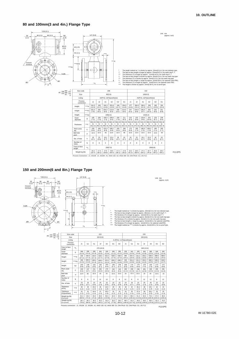
10. OUTLINE
IM 1E7B0-02E10-12
80 and 100mm(3 and 4in.) Flange Type
* The length marked as * is shorter by approx. 10mm(0.4 in.) for non indicator type.** The face-to-face length is longer by approx. 22mm(0.87 in.) for earth ring P, T.*** The thickness (T) is longer by approx. 11mm(0.43 in.) for earth ring P, T.** The face-to-face length is shorter by approx. 6mm(0.24 in.) for non earth ring type.*** The thickness (T) is shorter by approx. 3mm(0.12 in.) for non earth ring type.** The face-to-face length is longer by approx. 2mm(0.08 in.) for optional code /FRG.*** The thickness (T) is longer by approx. 1mm(0.04 in.) for optional code /FRG.**** The height is shorter by approx. 2mm(0.08 in.) for ex-proof type.
Unit: mm(approx. inch)
F11.EPS
*230 (9.1)
80 (3.1) 80 (3.1)30(1.2)
*40 (1.6)
ØDØC
N-Øh
147 (5.8)
**L
***T
49 (1.9)
54 (2.1)
****H1
****H
Ø123(4.8)
****(H2)Groundterminal
AEMGMNSC
AU
208210
JADG
Size code
Size
Lining
Process connection
208
80(3.0)
A(PFA), U(Polyurethane)
210
100(4.0)
A(PFA), U(Polyurethane)
J1
109(4.3) 132(5.2)
341.5(13.4)
J2 A1 A2 D2 G1 J1 J2 A1 A2 D2 G1
Height
Height
Height
Weight kg (lb)
Outer diameter D
Thickness
Dia. of hole
Number of holes
Face-to-facelength
Pitch circle dia.
****H
****H1
****H2
***T
h
N
**L 200(7.9) 250(9.8)
C
-
201.5(7.9)
185(7.3)
150(5.9)
19(0.7)
8
15.3(33.7)
25(1.0)to
31(1.2)
200(7.9)
160(6.3)
23(0.9)
8
17.3(38.1)
29(1.1)to
35(1.4)
190.5(7.5)
152.4(6.0)
19.1(0.7)
4
17.6(38.8)
31(1.2)to
38(1.5)
209.6(8.3)
168.1(6.6)
22.4(0.9)
8
20.6(45.4)
36(1.4)to
43(1.7)
200(7.9)
160(6.3)
18(0.7)
8
17.3(38.1)
26(1.0)to
32(1.3)
211(8.3)
168(6.6)
19(0.7)
4
17.8(39.2)
25(1.0)to
32(1.3)
210(8.3)
175(6.9)
19(0.7)
8
23.3(51.3)
25(1.0)to
31(1.5)
225(8.9)
185(7.3)
23(0.9)
8
26.5(58.4)
31(1.2)to
37(1.5)
228.6(9.0)
190.5(7.5)
19.1(0.7)
8
27.3(60.1)
31(1.2)to
38(1.5)
254(10.0)
200.2(7.9)
22.4(0.9)
8
34.7(76.4)
39(1.5)to
46(1.8)
220(8.7)
180(7.1)
18(0.7)
8
25.0(55.1)
26(1.0)to
32(1.3)
238(9.4)
195(7.7)
19(0.7)
4
26.4(58.1)
25(1.0)to
32(1.3)
349(13.7)
209(8.2)
344.3(13.6)
204.3(8.0)
353.8(13.9)
213.8(8.4)
349(13.7)
209(8.2)
354.5(14.0)
214.5(8.4)
377(14.8)
237(9.3)
384.5(15.1)
244.5(9.6)
386.3(15.2)
246.3(9.7)
399(15.7)
259(10.2)
382(15.0)
242(9.5)
391(15.4)
251(9.9)
Process Connection : J1; JIS10K J2; JIS20K A1; ANSI 150 A2; ANSI 300 D2; DIN PN16 G1; JIS F12
Bolt holepitch
45 45 4522.5 22.5 22.5 22.5 22.5 22.5
22.5 22.5 22.5
150 and 200mm(6 and 8in.) Flange Type
* The length marked as * is shorter by approx. 10mm(0.4 in.) for non indicator type.** The face-to-face length is longer by approx. 28mm(1.1 in.) for earth ring P, T.*** The thickness (T) is longer by approx. 14mm(0.55 in.) for earth ring P, T.** The face-to-face length is shorter by approx. 6mm(0.24 in.) for non earth ring type.*** The thickness (T) is shorter by approx. 3mm(0.12 in.) for non earth ring type.** The face-to-face length is longer by approx. 2mm(0.08 in.) for optional code/FRG.*** The thickness (T) is longer by approx. 1mm(0.04 in.) for optional code/FRG.**** The height marked as **** is shorter by approx. 2mm(0.08 in.) for ex-proof type.
F12.EPS
Unit: mm(approx. inch)
147 (5.8)*230 (9.1)
80(3.1)
80(3.1)
*40 (1.6)
30(1.2)
Groundterminal
49 (1.9)
54 (2.1)
**L
N-Øh
ØD ØC
***TØ123 (4.8)
****H1
H2
****H
Size code
Size
Lining
Face-to-facelength
Outerdiameter
280(11.0)
435(17.1)
295(11.6)
143(5.6)
240(9.4)
23(0.9)
30(1.2)
31(1.2)
31.3(68.9)
23(0.9)
33.4(1.3)
34.4(1.4)
33.3(73.3)
25(1.0)
36(1.4)
37(1.5)
39.3(86.6)
22(0.9)
44.5(1.8)
45.5(1.8)
50.3(110.8)
22(0.9)
30(1.2)
31(1.2)
32.3(71.1)
22(0.9)
30(1.2)
31(1.2)
33.3(73.3)
19(0.7)
32(1.3)
33(1.3)
48.3(106.4)
23(0.9)
36.4(1.4)
37.4(1.5)
51.3(113.0)
22(0.9)
32(1.2)
33(1.3)
47.3(104.2)
22(0.9)
32(1.2)
33(1.3)
48.3(106.4)
25(1.0)
38(1.5)
39(1.5)
54.3(120.0)
25(1.0)
49.1(1.9)
50.1(2.0)
75.3(165.9)
23(0.9)
30(1.2)
31(1.2)
43.3(95.4)
19(0.7)
30(1.2)
31(1.2)
33.3(73.3)
8 6 8 8 8 8 8 1212121212 8 12
290(11.4)
440.5(17.3)
300.5(11.8)
148(5.8)
247(9.7)
280(11.0)
245.5(17.1)
295.5(11.6)
143(5.6)
241(9.5)
305(12.0)
448.5(17.7)
308.5(12.1)
156(6.1)
260(10.2)
320(12.6)
455.5(17.9)
315.5(12.4)
163(6.4)
270(10.6)
285(11.2)
438.5(17.3)
298.5(11.8)
146(5.7)
240(9.4)
285(11.2)
438.5(17.3)
298.5(11.8)
146(5.7)
240(9.4)
330(13.0)
485(19.1)
345(13.6)
168(6.6)
290(11.4)
342(13.5)
491.5(19.4)
351.5(13.8)
174(6.9)
299(11.8)
345(13.6)
491.5(19.4)
351.5(13.8)
176(6.9)
298(11.7)
350(13.8)
495.5(19.5)
355.5(14.0)
178(7.0)
305(12.0)
380(15.0)
508.5(20.0)
368.5(14.5)
193(7.6)
330(13.0)
340(13.4)
488.5(19.2)
348.5(13.7)
173(6.8)
295(11.6)
340(13.4)
488.5(19.2)
348.5(13.7)
173(6.8)
295(11.6)
Height
Height
Height
Pitch circledia.
Number ofholes
Dia. of hole
Thickness(PFA)
Thickness(Polyurethane)
**L
D
****H
****H1
H2
C
N
h
***T
***T
Weight kg (lb)
215
150 (6.0) 200 (8.0)
220
Processconnection J1 G1 A1 J2 A2 D1 D2 J1 G1 A1 J2 A2 D1 D2
270 (10.6) 340 (13.4)
A (PFA). U (Polyurethane)
AEMGMNSC
AU
215220
JADG
-
Process connection : J1; JIS10K J2; JIS20K A1; ANSI 150 A2; ANSI 300 D1; DIN PN10 D2; DIN PN16 G1; JIS F12
34.3(75.6)
36.3(80.0)
42.3(93.2)
53.3(117.4)
35.3(77.8)
36.3(80.0)
53.3(117.4)
56.3(124.0)
52.3(115.2)
53.3(117.4)
59.3(130.6)
80.3(176.9)
48.3(106.4)
36.3(80.0)
Weight kg (lb)(General)
(Ex-proof)
Bolt holepitch
22.5 22.5
30 22.5 22.5 22.5 22.5 22.515 15 15 15 15 15

10. OUTLINE
IM 1E7B0-02E10-13
Unit: mm(approx. inch)
H1 H****
L**
H2φD
N-φh
φC
T***
for AE330,AE335,AE340
147 (5.8)30 (1.2)
49 (1.9)
*230 (9.1)
80(3.1)
80(3.1)
*40 (1.6)
Ground Terminal
φ123 (4.8)
37 (1.5)
* The length marked as * is shorter by approx. 10mm (0.4 in.) for non indicator type.
Lining code A : PFA lining U : Polyuretane lining** The face-to-face length is shorter by approx. 6mm(0.24 in.) for non earth ring type of AE325
and AE330, by approx. 10mm(0.39 in.) for non earth ring type of AE335 and AE340.*** The thickness(T) is shorter by approx. 3mm(0.12 in.) for non earth ring type of AE325
and AE330, by approx. 5mm(0.20 in.) for non earth ring type of AE335 and AE340.**** The height(H) is shorter by approx. 2mm(0.08 in.) for ex-proof type.
H****H1H2øDøCN
øhT***T***
L**e
H****H1H2øDøCN
øhT***T***
H****H1H2øDøCN
øhT***T***
General(G), Ex-proof(N)
A(PFA) , U(Polyurethane)
––––––––––––
––––––––––––
––––––––––––
––––––––––––
Height
Outer dia.Pitch circle dia.
Number of holesBolt hole pitch
Hole dia.Thickness(A)Thickness(U)
Weight (General) kg(lb) Weight (Ex-proof) kg(lb)
TypeSize code
SizeLining code
Face-to-faceEye bolt hole dia.
Height
Outer dia.Pitch circle dia.
Number of holesBolt hole pitch
Hole dia.Thickness(A)Thickness(U)
Weight (General) kg(lb) Weight (Ex-proof) kg(lb)
Height
Outer dia.Pitch circle dia.
Number of holesBolt hole pitch
Hole dia.Thickness(A)Thickness(U)
Weight (General) kg(lb) Weight (Ex-proof) kg(lb)
325250(10)
330300(12)
335350(14)
340400(16)
430(16.9)30(1.2)
553(21.8)461(18.1)206(8.1)406(16.0)362(14.3)
1215
26(1.0)38(1.5)39(1.5)
72.3(159.4)76.3(168.2)
500(19.7)30(1.2)
616(24.3)537(21.1)245(9.7)483(19.0)432(17.0)
1215
26(1.0)40(1.6)41(1.6)
92.3(203.5)96.3(212.3)
550(21.7)35(1.4)
662(26.1)597(23.5)270(10.6)533(21.0)476(18.7)
1215
29(1.1)45(1.8)46(1.8)
112.3(247.6)118.3(260.8)
600(23.6)35(1.4)
721(28.4)660(26.0)302(11.9)597(23.5)540(21.3)
1611.25
29(1.1)47(1.9)48(1.9)
147.3(324.7)154.3(340.2)
572(22.5)499(19.7)225(8.9)445(17.5)387(15.2)
1611.25
29(1.1)56(2.3)57(2.2)
77.3(170.4)81.3(179.2)
635(25.0)575(22.6)264(10.4)521(20.5)451(17.8)
1611.25
32(12.6)59(2.3)60(2.4)
100.3(221.1)104.3(229.9)
548(21.6)449(17.7)201(7.9)395(15.6)350(13.8)
1215
22(0.9)34(1.3)35(1.4)
66.3(146.2)70.3(155.0)
597(23.5)499(19.7)226(9.0)445(17.5)400(15.8)
1215
22(0.9)34(1.3)35(1.4)
83.3(183.6)87.3(192.5)
648(25.5)568(22.4)256(10.0)505(20.0)460(18.1)
1611.25
22(0.9)36(1.4)37(1.5)
96.3(212.3)102.3(225.5)
705(27.8)628(24.7)286(11.3)565(22.2)515(20.3)
1611.25
26(1.0)36(1.4)37(1.5)
124.3(274.0)131.3(289.5)
ANSI150
ANSI300
DINPN10
H****H1H2øDøCN
øhT***T***
Height
Outer dia.Pitch circle dia.
Number of holesBolt hole pitch
Hole dia.Thickness(A)Thickness(U)
Weight (General) kg(lb) Weight (Ex-proof) kg(lb)
553(21.8)459(18.1)206(8.1)405(15.9)355(14.0)
1215
22(0.9)34(1.3)35(1.4)
67.3(148.4)71.3(157.2)
604(23.8)514(20.2)233(9.2)460(18.1)410(16.1)
1215
22(0.9)36(1.4)37(1.5)
84.3(185.8)88.3(194.7)
DINPN16
JIS 10K
JIS 20K
JIS F12
H****H1H2øDøCNøh
T***T***
L**e
H****H1H2øDøCNøh
T***T***
H****H1H2øDøCNøh
T***T***
General(G), Ex-proof(N)
A(PFA) , U(Polyurethane)
––––––––––––
––––––––––––
Height
Outer dia.Pitch circle dia.
Number of holesBolt hole pitch
Hole dia.Thickness(A)Thickness(U)
Weight (General) kg(lb) Weight (Ex-proof) kg(lb)
TypeSize code
SizeLining code
Face-to-faceEye bolt hole dia.
Height
Outer dia.Pitch circle dia.
Number of holesBolt hole pitch
Hole dia.Thickness(A)Thickness(U)
Weight (General) kg(lb) Weight (Ex-proof) kg(lb)
Height
Outer dia.Pitch circle dia.
Number of holesBolt hole pitch
Hole dia.Thickness(A)Thickness(U)
Weight (General) kg(lb) Weight (Ex-proof) kg(lb)
325250(10)
330300(12)
335350(14)
340400(16)
430(16.9)30(1.2)
550(21.7)454(17.9)203(7.9)400(15.8)355(14.0)
1215
25(1.0)32(1.3)33(1.3)
66.3(146.2)70.3(155.0)
500(19.7)30(1.2)
597(23.5)499(19.7)226(9.0)445(17.5)400(15.8)
1611.25
25(1.0)34(1.3)35(1.4)
83.3(183.6)87.3(192.5)
550(21.7)35(1.4)
640(25.2)553(21.8)248(9.8)490(19.3)445(17.5)
1611.25
25(1.0)36(1.4)37(1.4)
96.3(212.3)102.3(225.5)
600(23.6)35(1.4)
703(27.7)623(24.5)283(11.1)560(22.0)510(20.1)
1611.25
27(1.1)38(1.5)39(1.5)
124.3(274.0)131.3(289.5)
565(22.2)484(19.1)218(8.6)430(16.9)380(15.0)
1215
27(1.1)42(1.7)43(1.7)
69.3(152.8)73.3(161.6)
614(24.2)534(21.0)243(9.6)480(18.9)430(16.9)
1611.25
27(1.1)44(1.7)45(1.8)
87.3(192.5)91.3(201.3)
555(21.9)464(18.3)208(8.2)410(16.1)360(14.2)
822.5
23(0.9)32(1.3)33(1.3)
66.3(146.2)70.3(155.0)
606(23.9)518(20.4)235(9.3)464(18.3)414(16.3)
1018
23(0.9)34(1.3)35(1.4)
83.3(183.6)87.3(192.5)
660(26.0)593(23.4)268(10.6)530(20.9)472(18.6)
1018
25(1.0)36(1.4)37(1.5)
96.3(212.3)102.3(225.5)
714(28.1)645(25.4)294(11.6)582(22.9)524(20.6)
1215
25(1.0)36(1.4)37(1.5)
124.3(274.0)131.3(289.5)
AE -
325 J330MG AG335MN UA340 D
ØD
30(1.2)
80 (3.1) 80 (3.1)147 (5.8)
Ø123 (4.8)
*230 (9.1)
*40(1.6)
ØD1
L2 L21.7 1.7
H2
H1
H
L
49 (1.9)
54 (2.1)
ØD2
Groundterminal
Size code
Size
Lining
Face-to-facelength
Height
202
25(1)
204
40(1.5)
205
50(2)
208
80(3)
210
100(4)
Ferrule length
Clamp O.D.
L
L2
D1
D2
D
H
H1
H2
Weight kg (lb)
176(6.9)
43(1.7)
25(1.0)
23(0.9)
74(2.9)
266(10.5)
126(5.0)
49(1.9)
5.8(12.8)
186(7.3)
41(1.6)
38(1.5)
36(1.4)
89.5(3.5)
289(11.4)
149(5.8)
61(2.4)
6.9(15.2)
206(8.1)
44(1.7)
51(2.0)
48(1.9)
103(4.1)
301(11.9)
161(6.3)
67(2.6)
8.3(18.3)
246(9.7)
44(1.7)
76(3.0)
72(2.8)
131(5.2)
340(13.4)
200(7.9)
81(3.2)
12.2(26.9)
206
65(2.5)
206(8.1)
44(1.7)
64(2.5)
60(2.4)
122(4.8)
314(12.4)
174(6.9)
70(2.8)
9.9(21.8)
272(10.7)
44(1.7)
102(4.0)
98(3.8)
171(6.7)
383(15.1)
243(9.5)
111(4.4)
17.7(39.0)
PFA
Height
Height
Ferrule innerdiameter
Ferrule outerdiameter
202204205206208210
AE MHSanitary, Integral Magnetic Flowmeter AE200MH
250 to 400mm(10 to 16in.) Flange Type
F13.EPS

11. PARAMETER SUMMARY
IM 1E7B0-02E11-1
11. PARAMETER SUMMARY
This chapter describes all parameters used by ADMAG AE.
• Description of Items
No.
AE AEBT BTName
Data Range, Units Deci-
mal
Point
Initial
SettingR/W Description
Parameter number on the ADMAG AE display panel
Parameter number on BT display
Parameter name on BT display
“00 - 20” are the numbers that can be set on the ADMAG AE. The desired number can be entered when “S” is displayed.
Indicates the range of allowable settings and the units used.8 alphanumerics can be entered when “8 ASC II characters” is specified.
Indicate initially set value (When shipped from the factory)
R : Display only W : Write enabled
Describes the nature of the parameter
Numbers indicate the position of decimal point and its range of movement within the data display.ADMAG AE display panel :
8 8 : 483828180
Example :0 to 4: Can be moved in the range 0 to 44 : Fixed at 4
Description

11. PARAMETER SUMMARY
IM 1E7B0-02E11-2
No.
AE BT AE BTName
Data Range, Units Deci-mal Point
Initial Setting R/W Description
DISPLAY
FLOW RATE(%)
FLOW RATE
TOTAL
SELF CHECK
- 8.0(-108.0) to 108.0%
±300.0m/s
0 to 999999
GOODERRORµP FAULTEEPROM FAULTA/D (L) FAULTA/D (H) FAULTSIGNAL OVERFLOWCOIL OPENSPAN VEL.>10m/sSPAN VEL.<0.3m/sP. SPAN>1000p/sP. SPAN>500p/sP. SPAN>25p/sP. SPAN>15p/sP. SPAN>10p/sP. SPAN>5p/sP. SPAN<0.0001p/sT. SPAN>1000p/sT. SPAN<0.0001p/s4 · 20 LMT ERROREMPTY PIPEMULTI RANGE EROOR
Major display items
Displays instantaneous flow in %
Displays instantaneous flow in actual units
Displays forward direction totalization values
Self checkIndicates nature of alarm when alarm occurs.
A00
A10
A20
A30
A60
1
0 to 4
0
R
R
R
W
R
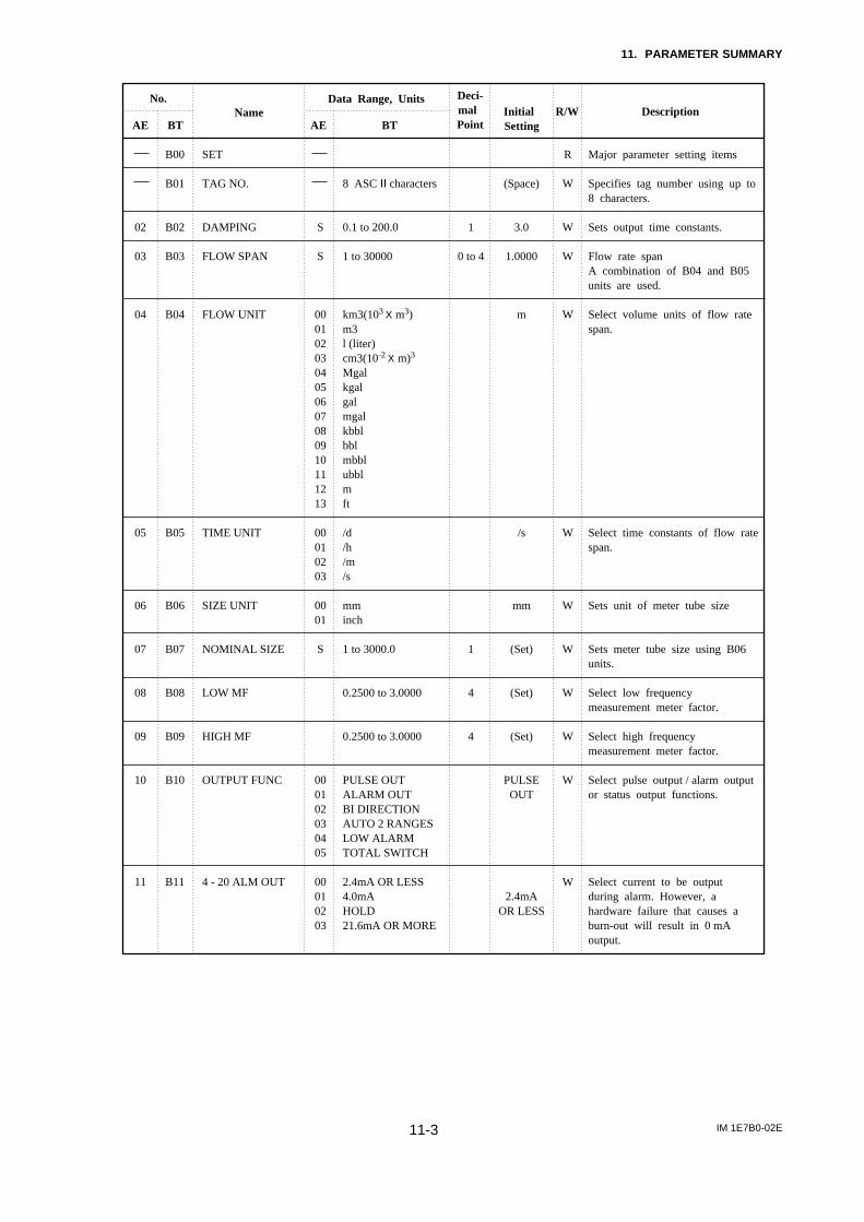
11. PARAMETER SUMMARY
IM 1E7B0-02E11-3
No.
AE BT AE BTName
Data Range, Units Deci-mal Point
Initial Setting
R/W Description
SET
TAG NO.
DAMPING
FLOW SPAN
FLOW UNIT
TIME UNIT
SIZE UNIT
NOMINAL SIZE
LOW MF
HIGH MF
OUTPUT FUNC
4 - 20 ALM OUT
8 ASC II characters
0.1 to 200.0
1 to 30000
km3(103 X m3)m3l (liter)cm3(10-2 X m)3
Mgalkgalgalmgalkbblbblmbblubblmft
/d/h/m/s
mminch
1 to 3000.0
0.2500 to 3.0000
0.2500 to 3.0000
PULSE OUTALARM OUTBI DIRECTIONAUTO 2 RANGESLOW ALARMTOTAL SWITCH
2.4mA OR LESS4.0mAHOLD21.6mA OR MORE
Major parameter setting items
Specifies tag number using up to 8 characters.
Sets output time constants.
Flow rate spanA combination of B04 and B05 units are used.
Select volume units of flow rate span.
Select time constants of flow rate span.
Sets unit of meter tube size
Sets meter tube size using B06 units.
Select low frequency measurement meter factor.
Select high frequency measurement meter factor.
Select pulse output / alarm output or status output functions.
Select current to be output during alarm. However, a hardware failure that causes a burn-out will result in 0 mA output.
B00
B01
B02
B03
B04
B05
B06
B07
B08
B09
B10
B11
S
S
0001020304050607080910111213
00010203
0001
S
000102030405
00010203
02
03
04
05
06
07
08
09
10
11
1
0 to 4
1
4
4
R
W
W
W
W
W
W
W
W
W
W
W
(Space)
3.0
1.0000
m
/s
mm
(Set)
(Set)
(Set)
PULSEOUT
2.4mAOR LESS

11. PARAMETER SUMMARY
IM 1E7B0-02E11-4
No.
AE BT AE BTName
Data Range, Units Deci-mal
Point
Initial Setting R/W Description
POWER FREQ
VELOCITY CHK
FLOW DIR
REV. SPAN
BI. DIREC HYS
FOR. SPAN 2
AUTO RNG HYS
LOW ALARM
L. ALARM HYS
SELF CHECK
ADJUST
ZERO TUNING
MAGFLOW ZERO
SELF CHECK
47.00 to 63.00
0 to 20.000
FORWARDREVERSE
1 to 30000
0 to 10
1 to 30000
0 to 15
-10 to 110
0 to 10
GOOD MULTI RANGE ERROR
INHIBITENABLE
0 to –99.99
GOOD MULTI RANGE ERROR
Power frequency setting
Range span displayed in m/s
Select flow direction
Span for reverse direction flow mesuring
Direct / reverse flow mesuring hysteresis
Second span for forward direction multi - range
Two range transfer hysteresis
Comparsion level for alarm output at low flow limits
Hysteresis for alarm output at low flow limits
Self checkIndicates nature of alarm when alarm occurs.
Parameter for setting auto zero adjust
Parameter for setting auto zero adjust
Displays zero correction
Self checkIndicates nature of alarm when alarm occurs.
B12
B13
B14
B30
B31
B33
B34
B36
B37
B60
C00
C01
C02
C60
S
S
0001
S
S
S
S
S
S
00
21
0001
S
00
21
12
13
14
30
31
33
34
36
37
C1
C2
2
3
0 to 4
0
0 to 4
0
0
0
2
W
R
W
W
W
W
W
W
W
R
R
W
W
R
50.00
FORWARD
1.0000
2
1.0000
10
-10
5
ENABLE
0.00

11. PARAMETER SUMMARY
IM 1E7B0-02E11-5
No.
AE BT AE BTName
Data Range, Units Deci-mal
Point
Initial Setting R/W Description
RATE (%)RATEFOR. TOTALREV. TOTALDIF. TOTALRATE(%) / FOR. TTLRATE / FOR. TTLRATE / RATE(%)RATE(%) / REV. TTLRATE / REV. TTLRATE(%) / DIF. TTLRATE / DIF. TTL
NOT PROVIDEDPROVIDED
0 to 30000
8 ASCII characters
GOOD
MULTI RANGE ERROR
n UNIT / Pµ UNIT / Pm UNIT / PUNIT / Pk UNIT / PM UNIT / PPULSE / S
0 to 30000
0 to 100
INHIBITENABLE
0 to 999999
D00
D01
D02
D03
D10
D60
E00
E01
E02
E03
E04
E05
000102030405
060708
0910
11
0001
S
00
21
00010203040506
S
S
0001
S
d1
d2
d3
E1
E2
E3
E4
E5
Display selection items
Display panel selections
Selects whether special units are to be used for instantaneous flow rates
Sets the value to be displayed in the special unit at 100% output
Sets the special instantaneous flow rate unit
Self checkIndicates nature of alarm when alarm occurs
Totalization display items
Sets flow rate unit per pulse for totalization display
Sets flow rate per pulse for totalization display
Sets the range in vicinity of 0% within which totalization will be halted
Totalization preset(reset) enabled / inhibited
Sets preset (reset) value
DISP SEL
DISP SELECT
FL USER SEL
FL USER SPAN
FL USER UNIT
SELF CHECK
TOTAL SET
TOTAL UNIT
TOTAL SCALE
TOTAL LOWCUT
TOTAL SET
TL SET VALUE
0 to 4
0 to 4
0
0
RATE(%)
NOTPROVIDED
100
Space
PULSE/S
0
3
INHIBIT
0
R
W
W
W
W
R
R
W
W
W
W
W

11. PARAMETER SUMMARY
IM 1E7B0-02E11-6
No.
AE BT AE BTName
Data Range, Units Deci-mal
Point
Initial Setting R/W Description
0 to 999999
8 ASCII characters
0 to 999999
0 to 999999
GOOD
MULTI RANGE ERROR
n UNIT / Pµ UNIT / Pm UNIT / PUNIT / Pk UNIT / PM UNIT / PPULSE / S
0 to 30000
0 to 100
50% DUTY0.5 msec1 msec20 msec33 msec50 msec100 msec
GOOD MULTI RANGE ERROR
E06
E10
E11
E12
E60
F00
F01
F02
F03
F04
F60
S
S
00
21
00010203040506
S
S
00010203040506
00
21
E6
F1
F2
F3
F4
Set the totalization switch level
Sets special totalization units
Display differential totalizationvalues
Display differential totalizationvalues
Self checkIndicates ature of alarm whenalarm occurs.
Pulse output items
Selects pulse rate units
Sets pulse rate
Sets the range in vicinity of 0%wihtin which pulse output willbe halted
Sets width of pulse output
Self checkIndicates nature of alarm whenalarm occurs
TOTAL SWITCH
TL USER UNIT
REV. TOTAL
DIF. TOTAL
SELF CHECK
PULSE SET
PULSE UNIT
PULSE SCALE
PULSE LOWCUT
PULSE WIDTH
SELF CHECK
0
0
0
0 to 4
0
0
Space
0
0
PULSE/S
0
3
50%DUTY
W
W
R
R
R
R
W
W
W
W
R
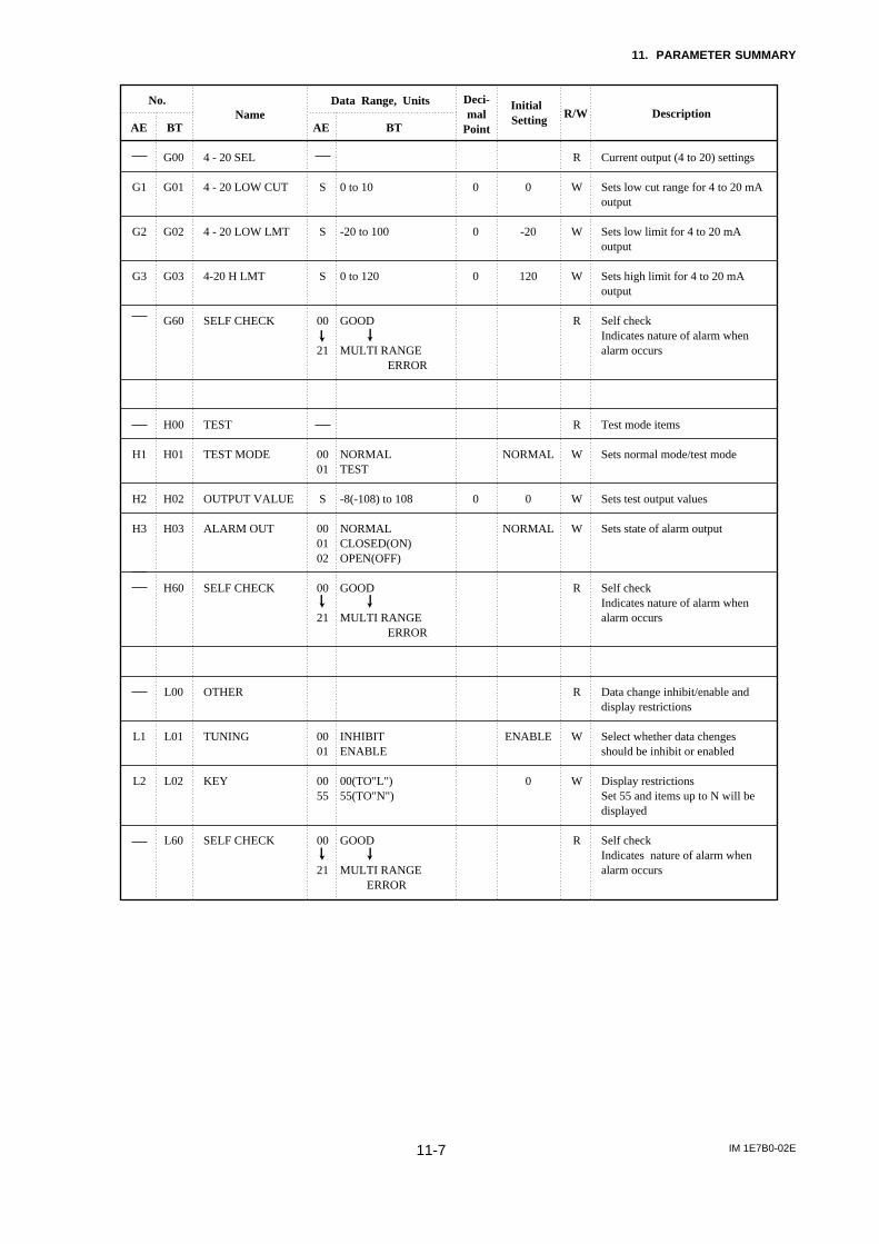
11. PARAMETER SUMMARY
IM 1E7B0-02E11-7
No.
AE BT AE BTName
Data Range, Units Deci-mal
Point
Initial Setting R/W Description
0 to 10
-20 to 100
0 to 120
GOOD MULTI RANGE ERROR
NORMALTEST
-8(-108) to 108
NORMALCLOSED(ON)OPEN(OFF)
GOOD
MULTI RANGE ERROR
INHIBITENABLE
00(TO"L")55(TO"N")
GOOD MULTI RANGE ERROR
G00
G01
G02
G03
G60
H00
H01
H02
H03
H60
L00
L01
L02
L60
S
S
S
00
21
0001
S
000102
00
21
0001
0055
00
21
G1
G2
G3
H1
H2
H3
L1
L2
Current output (4 to 20) settings
Sets low cut range for 4 to 20 mA output
Sets low limit for 4 to 20 mAoutput
Sets high limit for 4 to 20 mAoutput
Self checkIndicates nature of alarm whenalarm occurs
Test mode items
Sets normal mode/test mode
Sets test output values
Sets state of alarm output
Self checkIndicates nature of alarm whenalarm occurs
Data change inhibit/enable anddisplay restrictions
Select whether data chengesshould be inhibit or enabled
Display restrictionsSet 55 and items up to N will bedisplayed
Self checkIndicates nature of alarm whenalarm occurs
4 - 20 SEL
4 - 20 LOW CUT
4 - 20 LOW LMT
4-20 H LMT
SELF CHECK
TEST
TEST MODE
OUTPUT VALUE
ALARM OUT
SELF CHECK
OTHER
TUNING
KEY
SELF CHECK
0
0
0
0
0
-20
120
NORMAL
0
NORMAL
ENABLE
0
R
W
W
W
R
R
W
W
W
R
R
W
W
R

11. PARAMETER SUMMARY
IM 1E7B0-02E11-8
No.
AE BT AE BTName
Data Range, Units Deci-mal
Point
Initial Setting R/W Description
NO DAMPDAMP
ONOFF
0 to 10
0 to 15
YESNO
YESNO
ALARMNO ALARM
GOOD MULTI RANGE ERROR
N00
N01
N02
N03
N04
N05
N06
N07
N60
0001
0001
S
S
0001
0001
0001
00
21
n1
n2
n3
n4
n5
n6
n7
Select whether instantaneousflow rate values or dampingderived flow rate values are tobe used in totalization / pulse
Select whether the pulse outputtrannsistor is to be set to ONACTIVE or OFF ACTIVE
Sets the level to reduce outputfluctuation.
Sets the dead time to reduce outputfluctuation. When "0" is set, "Rate limit" is not available.
Select whether the internalfrequency is to be synchronizedwith the power supply or not.
Counteraction of pulseing flow
Select whether the detectingempty pipe function is to be usedas an alarm or not.
Self checkIndicates nature of alarm whenalarm occurs
APPL SET
TOTAL / PULSE
PLSE MODE
RATE LIMIT
DEAD TIME
POWER SYNCH
PULSING FLOW
EMPTY PIPE
SELF CHECK
0
0
DAMP
ON
0 to 5
0
YES
NO
ALARM
R
W
W
W
W
W
W
W
R

IM 1E7B0-02E12-1
12. EXPLOSION PROTECTED TYPE INSTRUMENT
12. EXPLOSION PROTECTED TYPEINSTRUMENT
In this section, further requirements and differences forexplosion proof type instrument are described. Forexplosion proof type instrument, the description in thischapter is prior to other description in this User'sManual.
CAUTION
The terminal box cover and display cover islocked by special screw. In case of opening thecover, please use the Hexagonal Wrenchattached.
CAUTION
Be sure to lock the cover with the special screwusing the Hexagonal Wrench attached aftertightening the cover.
12.1 CENELEC ATEX(KEMA)
WARNING
Only trained persons use this instrument inindustrial locations.
(1) Technical DataNo. KEMA 02ATEX2022Group category : II 2GEEx dme[ia]IIC T6...T3Electrode Circuit Um : 250V ac/dcExcitation Circuit : 130Vpeak max. 72/75Hz,
0.2A max.Temp. Class. T6 T5 T4 T3Max Process Temp. +70 +85 +120
+130°CEnclosure : IP67
(2) Electrical ConnectionThe type of electrical connection is stamped near theelectrical connection port accordiing to the followingcodes.
Screw Size MarkingISO M20x1.5 female MANSI 1/2NPT female A
(3) Installation
WARNING
• All wiring shall comply with local installationrequirements and local electrical code.
• In hazadous locations, the cable entry devicesshall be of a certified flameproof type, suitablefor the conditions of use and correctly installed.
• Unused apertures shall be closed with suitableflameproof certified blanking elements. (Theplug attached is flameproof certified.)
(4) Operation
WARNING
• Wait 10 min. after power is turned off, deforeopening the covers.
• Take care not to generate mechanical sparkwhen access to the instrument and peripheraldevices in hazardous locations.
(5) Maintenance and Repair
WARNING
The instrument modification or parts replacementby other than authorized representative ofYokogawa Electric Corporation is prohibited andwill void the certification.

IM 1E7B0-02E12-2
12. EXPLOSION PROTECTED TYPE INSTRUMENT
(6) Data Plate
TOKYO 180-8750 JAPAN
AFTER DE-ENERGIZING, DELAY10 MINUTES BEFORE OPENING.
WARNING
ENCLOSURE : IP67ELECTRODE CIRCUIT Um : 250V ac/dc
0344 2G
Tamb.
FLUID PRESS
FLUID TEMP.
IM: User's ManualMAGNETIC FLOWMETER
STYLE
30VDC 0.2Amax.
MODEL
SUFFIX
SIZE
METERFACTOR
SUPPLY
CURRENTOUTPUT
PULSEOUTPUT
FULLSCALE
LININGMATERIAL
ELECTRODEMATERIAL
ACCURACYRATING
No.
L
H
m
4-20mA
(0-750Ω)
(JIS B7554)
-0.1 MPa MIN. (SEE IM)
12.5DCV
+60°C MAX. (SEE IM)
MAX.PROCESS TEMP.(°C) : +70 +85 +120 +130
EEx dme[ia]IIC T6...T3TEMP.CLASS : T6 T5 T4 T3
No. : KEMA 02ATEX2022
SEE THE NOTES AT BELOWAND SEE IM
Made in Japan
VAC 47–63 Hz 36 VA 12.5
MODEL : Specified model codeSUFFIX : Suffix codes of the model codeSTYLE : Specified style codeSIZE : Nominal size of apparatusMETER FACTOR : Sensor constant number of apparatusSUPPLY : Power supply voltage of apparatusFULL SCALE : Meter rangeCURRENT OUTPUT : Output signal of apparatusPULSE OUTPUT : Output signal of apparatusLINING MATERIAL : Material of linerELECTRODE MATERIAL : Material of electrodesACCURACY RATING : Accuracy of apparatusFLUIDTEMP. : Fluid temperature of apparatusFLUIDPRESS : Fluid pressure of apparatusTamb : Ambient temperatureNo. : Manufacturing serial numberCE : CE markingExII 2G : Group II Catergory 2 Gas atomosphereKEMA No. : KEMA 02ATEX2022 : Certificate numberEExdem[ia]IICT6...T4 : Protection type and temp. classELECTRODE CIRCUIT Um : Voltage of electrode circuitENCLOSURE : Enclosure protection numberIM : User's Manual
WARNING: Warning to apparatusYOKOGAWA TOKYO 180-8750 JAPAN :
Name and address of manufacturer*1) The third figure from the last shows the last one
figure of the year of production. For example, theyear of production of the product engraved asfollows is year 1998.
No. F261GA091 813↑
Produced in 1998
*2) The identification number of the notified body :0344
*3) The product-producing country
12.2 FM(1) Technical Data• Explosionproof for Class I Division 1 Groups A, B,
C & D. Dust-ignitionproof for Class II/III Division 1Groups E, F & G. Intrinsically safe (electrode) forClass I Division 1 Groups A, B, C & DElectrode circuit Vmax : 250V ac/dcTemp. Class. T6
Enclosure : NEMA 4X
• Nonincendive for Class I, Division 2, Groups A, B,C & D ; Suitable for Class II, Division 2, Groups F& G ; Class III, Division 1 and 2Intrinsically safe (electrode) for Class I Division 1Groups A, B, C & DElectrode Circuit Vmax : 250V ac/dcExcitation Circuit : 130Vp 72/75HzTemp. Code : T5Enclosure : NEMA 4X
(2) Installation
WARNING
• All wiring shall comply with national electricalcode ANSI/NFPA 70 and local electrical code.
• In hazardous locations, wiring to be in conduitas shown in Figure 12.2.1.
(3) Operation
WARNING
• Open circuit before opening the covers andseal all conduits with in 18 inches in hazardouslocations.
• Take care not to generate mechanical sparkwhen access to the instrument and peripheraldevices in hazardous locations.
(4) Maintenance and Repair
WARNING
The instrument modification or parts replacementby other than authorized representative ofYokogawa Electric Corporation is prohibited andwill void the approval of Factory Mutual Re-search Corporation.
ConduitMagnetic Flow Converter
Sealing Fitting
HAZARDOUS LOCATIONS
18" (457 mm) Max.F0601.EPS
Figure 12.2.1 Conduit Wiring

IM 1E7B0-02E12-3
12. EXPLOSION PROTECTED TYPE INSTRUMENT
12.3 CSA(1) Technical Data• Explosionproof for Class I, Groups B, C & D ; Class
II, Groups E, F & G ; Class IIIElectrode: Intrinsically safe for Class I, Division 1,Groups A, B, C & DElectrode Circuit Vmax: 250V ac/dcTemp. Code T6 T5 T4Process Temp 70 85 120°CEnclosure: Type 4
• Nonincendive for Class I, Division 2, Groups A, B,C & D ; Suitable for Class II, Division 2, Groups E,F and G ; Class IIIElectrode: Intrinsically safe for Class I, Division 1,Groups A, B, C & DElectrode Circuit Vmax: 250V ac/dcExcitation Circuit: 130Vp 72/75Hz, 11VAmaxTemp. Code T5 T4Process Temp 85 120°CEnclosure: Type 4
(2) Installation
WARNING
All wiring shall comply with Canadian ElectricalCode Part I and Local Electrical Codes.In hazardous location, wiring shall be in conduitas shown in Figure 12.3.1.CAUTION : SEAL ALL CONDUITS WITHN
50cm OF THE ENCLOSURE’ UNSCELLEMENT DOIT ÉTREINSTALLÉ À MOINS DE 50cm DUBOÎTIER.
(3) Operation
WARNING
CAUTION : OPEN CIRCUIT BEFORE REMOV-ING COVER.OUVRIR LE CIRCUIT AVANTD’ENLEVER LE COUVERCLE.
Take care not to generate mechanical sparkwhen access to the instrument and peripheraldevices in hazardous location.
(4) Maintenance and Repair
WARNING
The instrument modification or parts replacementby other than authorized representative ofYOKOGAWA Electric Corporation orYOKOGAWA Corporation of AMERICA isprohibited and will void Canadian StandardsExplosionproof Certification.
ConduitMagnetic Flow Converter
Sealing Fitting
HAZARDOUS LOCATIONS
50 cm Max.F0602.EPS
Figure 12.3.1 Conduit Wiring
12.4 SAA
WARNING
Only trained persons use this instrument inindustrial locations .
(1) Technical DataSA Certificate No. AUS Ex 3210XType of Protection Ex dm(ia)II C T6 IP67Electrode Circuit Um 250V ac/dcExcitation Circuit 130Vp 72/75HzTemperature Class T6 T5 T4Process Temperature 70 85 120°C
(2) Installation
WARNING
• All wiring shall comply with local installationrequirements and local electrical code.
• In hazardous locations, the cable entry devicesshall be of a certified flameproof type, suitablefor the contidions of use and correctrlyinstalled.
• Unused apertures shall be closed with suitableflameproof certified blanking elements. (Theplug attached is flameproof certified.)
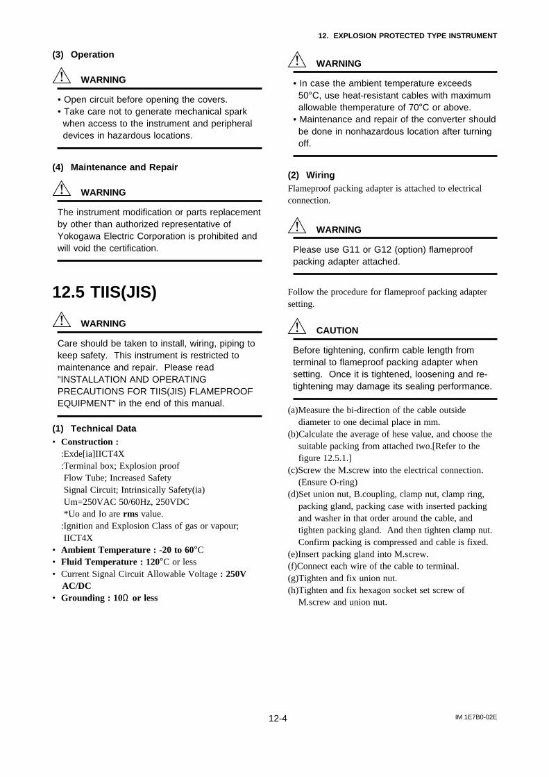
IM 1E7B0-02E12-4
12. EXPLOSION PROTECTED TYPE INSTRUMENT
(3) Operation
WARNING
• Open circuit before opening the covers.• Take care not to generate mechanical spark
when access to the instrument and peripheraldevices in hazardous locations.
(4) Maintenance and Repair
WARNING
The instrument modification or parts replacementby other than authorized representative ofYokogawa Electric Corporation is prohibited andwill void the certification.
12.5 TIIS(JIS)
WARNING
Care should be taken to install, wiring, piping tokeep safety. This instrument is restricted tomaintenance and repair. Please read"INSTALLATION AND OPERATINGPRECAUTIONS FOR TIIS(JIS) FLAMEPROOFEQUIPMENT" in the end of this manual.
(1) Technical Data• Construction :
:Exde[ia]IICT4X:Terminal box; Explosion proof Flow Tube; Increased Safety Signal Circuit; Intrinsically Safety(ia) Um=250VAC 50/60Hz, 250VDC *Uo and Io are rms value.:Ignition and Explosion Class of gas or vapour; IICT4X
• Ambient Temperature : -20 to 60°C• Fluid Temperature : 120°C or less• Current Signal Circuit Allowable Voltage : 250V
AC/DC• Grounding : 10Ω or less
WARNING
• In case the ambient temperature exceeds50°C, use heat-resistant cables with maximumallowable themperature of 70°C or above.
• Maintenance and repair of the converter shouldbe done in nonhazardous location after turningoff.
(2) WiringFlameproof packing adapter is attached to electricalconnection.
WARNING
Please use G11 or G12 (option) flameproofpacking adapter attached.
Follow the procedure for flameproof packing adaptersetting.
CAUTION
Before tightening, confirm cable length fromterminal to flameproof packing adapter whensetting. Once it is tightened, loosening and re-tightening may damage its sealing performance.
(a)Measure the bi-direction of the cable outsidediameter to one decimal place in mm.
(b)Calculate the average of hese value, and choose thesuitable packing from attached two.[Refer to thefigure 12.5.1.]
(c)Screw the M.screw into the electrical connection.(Ensure O-ring)
(d)Set union nut, B.coupling, clamp nut, clamp ring,packing gland, packing case with inserted packingand washer in that order around the cable, andtighten packing gland. And then tighten clamp nut.Confirm packing is compressed and cable is fixed.
(e)Insert packing gland into M.screw.(f)Connect each wire of the cable to terminal.(g)Tighten and fix union nut.(h)Tighten and fix hexagon socket set screw of
M.screw and union nut.

IM 1E7B0-02E12-5
12. EXPLOSION PROTECTED TYPE INSTRUMENT
T1
T2
L
18(0.71)
G
F
D
C
16.5(0.65)
*Packing(Choose from the table belowdepend on cable outside diameter)
Unit : mm (Approx. inch)
Adapter body(M. Screw)
Packing case
Hexagon socket set screw
O-Ring
Packing *
O-Ring
O-Ring
Washer
Union nut
Packing gland
Clamp ring
Clamp nut
O-Ring
B.coupling
Cable(user's scope)
Hexagon socket set screw
0.26
(0.57)
8.0 to 10.0 (0.31 to 0.39)
10.0 to 12.0 (0.39 to 0.47)
16 8-10
16 10-12
Identification
mark
Weightkg(lb)
Packing diameter
Cable outer diameterT1 T2 C D L
Dimension
G 1/2 G 1/235
(1.38)
39
(1.54)
94.5
(3.72)
10.0(0.39)
12.0(0.47)
20.0
(0.79)
F G
Figure 12.5.1 Flameproof Packing Adapter

IM 1E7B0-02E13-1
13. PRESSURE EQUIPMENT DIRECTIVE
13. PRESSURE EQUIPMENT DIRECTIVEThis chapter is described further requirements andnotices concerning the PED (Pressure EquipmentDirective). The description in this chapter is prior toother description in this User's Manual.
(1) Technical DataModule : HType of Equipment : PipingType of Fluid : Liquid and GasGroup of Fluid : 1 and 2
General Purpose / Explosion Proof
MODEL
AE102MG/MN/SC
AE105MG/MN/SC
AE110MG/MN/SC
AE115MG/MN/SC
AE202MG/MN/SC
AE204MG/MN/SCAE205MG/MN/SCAE206MG/MN/SCAE208MG/MN/SCAE210MG/MN/SCAE212MG/MN/SCAE215MG/MN/SCAE220MG/MN/SCAE325MG/MN/SCAE330MG/MN/SCAE335MG/MN/SCAE340MG/MN/SC
DN(mm)*
2.5
5
10
15
25
40506580
100125150200250300350400
PS(MPa)*
4
4
4
4
4
442222222211
PS·DN(MPa·mm)
10
20
40
60
100
160200130160200250300400500600700800
CATEGORY**
Article 3,paragraph 3
Article 3,paragraph 3
Article 3,paragraph 3
Article 3,paragraph 3
Article 3,paragraph 3
IIIIIIIIIIIIIIIIIIIIIIIIIIIII
***
***
***
***
***
T1301.EPS
Sanitary
MODEL
AE202MH
AE204MHAE205MHAE206MHAE208MHAE210MH
DN(mm)*
25
40506580
100
PS(MPa)*
1
11111
PS·DN(MPa·mm)
25
40506580
100
CATEGORY**
Article 3,paragraph 3
IIIII
***
T01302.EPS
* PS: Maximum allowable pressure for Flow TubeDN: Nominal size
** Referred to Table 6 covered by ANNEX II of ECDirective on Pressure Equipment Directive 97/23/EC)
*** AE102MG/MN/SC to AE202MG/MN/SC, andAE202MH are not attached CE mark of PEDbecause they do not come under CE marking ofPED.
(2) Installation
WARNING
• Please tighten the bolts for piping-joint accord-ing to the prescribed torque values.
• Please take measure to protect the flowmetersfrom forces caused by vibration through piping.
(3) Operation
WARNING
• The temperature and pressure of fluid shouldbe applied under the normal operating condi-tion.
• The ambient temperature should be appliedunder the normal operating condition.
• Please pay attention to prevent the excessivepressure like water hammer, etc. When waterhammer is to be occurred, please takemeasures to prevent the pressure fromexceeding PS(maximum allowable pressure) bysetting the safety valve, etc. at the system andthe like.
• When external fire is to be occurred, pleasetake safety measures at the device or systemnot to influence the flowmeters.
• Please avoid the fluid exceeding the corrosionproof of lining and electrode.
• Please pay attention not to be abrade themetal pipe, when the fluid to abrade the liningsuch as slurry and sand are contained.

EX-B03E1
INSTALLATION AND OPERATING PRECAUTIONS FOR TIIS(JIS) FLAMEPROOF EQUIPMENT
INSTALLATION AND OPERATING PRECAUTIONS FORTIIS(JIS) FLAMEPROOF EQUIPMENT
Apparatus Certified Under Technical Criteria(IEC-compatible Standards)
1. GeneralThe following describes precautions on electrical apparatusof flameproof construction (hereinafter referred to as
flameproof apparatus) in explosion-protected apparatus.
Following the Labour Safety and Health Laws of Japan,
flameproof apparatus is subjected to type tests to meet eitherthe technical criteria for explosionproof electrical machineryand equipment (standards notification no. 556 from theJapanese Ministry of Health, Labour and Welfare) (hereinaf-ter referred to as technical criteria), in conformity with theIEC Standards, or the “Recommended Practice for Explosion-
Protected Electrical Installations in General Industries,”published in 1979. These certified apparatus can be used inhazardous locations where explosive or inflammable gases orvapours may be present.
Certified apparatus includes a certification label and anequipment nameplate with the specifications necessary forexplosion requirements as well as precautions on explosionprotection. Please confirm these precautionary items and usethem to meet specification requirements.
For electrical wiring and maintenance servicing, please referto “Internal Wiring Rules” in the Electrical InstallationTechnical Standards as well as “USER’S GUIDELINES for
Electrical Installations for Explosive Gas Atmospheres inGeneral Industry,” published in 1994.
To meet flameproof requirements, equipment that can betermed “flameproof” must:
(1) Be certified by a Japanese public authority in accordance
with the Labour Safety and Health Laws of Japan andhave a certification label in an appropriate location on itscase, and
(2) Be used in compliance with the specifications marked onits certification label, equipment nameplate andprecautionary information furnished.
2. Electrical Apparatus of Flame-proof Type of Explosion-Pro-tected Construction
Electrical apparatus which is of flameproof construction is
subjected to a type test and certified by the Japanese Ministryof Labour aiming at preventing explosion caused by electricalapparatus in a factory or any location where inflammablegases or vapours may be present. The flameproof
construction is of completely enclosed type and its enclosureshall endure explosive pressures in cases where explosivegases or vapours entering the enclosure cause explosion. Inaddition, the enclosure construction shall be such that flamecaused by explosion does not ignite gases or vapours outside
the enclosure.
In this manual, the word "flameproof" is applied to theflameproof equipment combined with the types of protection
"e", "o", "i", and "d" as well as flameproof equipment.
3. Terminology
(1) EnclosureAn outer shell of an electrical apparatus, which encloses liveparts and thus is needed to configure explosion-protectedconstruction.
(2) ShroudA component part which is so designed that the fastening of
joint surfaces cannot be loosened unless a special tool isused.
(3) Enclosure internal volumeThis is indicated by:— the total internal volume of theflameproof enclosure minus the volume of the internalcomponents essential to equipment functions.
(4) Path length of joint surfaceOn a joint surface, the length of the shortest path throughwhich flame flows from the inside to outside of theflameproof enclosure. This definition cannot be applied tothreaded joints.
(5) Gaps between joint surfacesThe physical distance between two mating surfaces, ordifferences in diameters if the mating surfaces are cylindrical.
Note: The permissible sizes of gaps between joint surfaces, the pathlength of a joint surface and the number of joint threads aredetermined by such factors as the enclosure’s internalvolume, joint and mating surface construction, and theexplosion classification of the specified gases and vapours.

EX-B03E2
INSTALLATION AND OPERATING PRECAUTIONS FOR TIIS(JIS) FLAMEPROOF EQUIPMENT
4. Installation of FlameproofApparatus
(1) Installation AreaFlameproof apparatus may be installed, in accordance with
applicable gases, in a hazardous area in Zone 1 or 2, wherethe specified gases are present. Those apparatus shall not beinstalled in a hazardous area in Zone 0.
Note: Hazardous areas are classified in zones based upon thefrequency of the appearance and the duration of an explosivegas atmosphere as follows:Zone 0: An area in which an explosive gas atmosphere is
present continuously or is present for long periods.Zone 1: An area in which an explosive gas atmosphere is
likely to occur in normal operation.Zone 2: An area in which an explosive gas atmosphere is not
likely to occur in normal operation and if it doesoccur it will exist for a short period only.
(2) Environmental ConditionsThe standard environmental condition for the installation offlameproof apparatus is limited to an ambient temperaturerange from –20°C to +40°C (for products certified underTechnical Criteria). However, some field-mountedinstruments may be certified at an ambient temperature up to+60°C as indicated on the instrument nameplates. If the
flameproof apparatus are exposed to direct sunshine orradiant heat from plant facilities, appropriate thermalprotection measures shall be taken.
5. External Wiring for FlameproofApparatus
Flameproof apparatus require cable wiring or flameproof
metal conduits for their electrical connections. For cablewiring, cable glands (cable entry devices for flameproof type)to wiring connections shall be attached. For metal conduits,attach sealing fittings as close to wiring connections aspossible and completely seal the apparatus. All non-livemetal parts such as the enclosure shall be securely grounded.
For details, see the “USER’S GUIDELINES for ElectricalInstallations for Explosive Gas Atmospheres in GeneralIndustry,” published in 1994.
(1) Cable Wiring• For cable wiring, cable glands (cable entry devices for
flameproof type) specified or supplied with the apparatus
shall be directly attached to the wiring connections tocomplete sealing of the apparatus.
• Screws that connect cable glands to the apparatus arethose for G-type parallel pipe threads (JIS B 0202) withno sealing property. To protect the apparatus fromcorrosive gases or moisture, apply nonhardening sealant
such as liquid gaskets to those threads for waterproofing.
• Specific cables shall be used as recommended by the“USER’S GUIDELINES for Electrical Installations for
Explosive Gas Atmospheres in General Industry,”published in 1994.
• In necessary, appropriate protective pipes (conduit orflexible pipes), ducts or trays shall be used forpreventing the cable run (outside the cable glands) fromdamage.
• To prevent explosive atmosphere from being propagatedform Zone 1 or 2 hazardous location to any differentlocation or non-hazardous location through the protectivepipe or duct, apply sealing of the protective pipes in thevicinity of individual boundaries, or fill the ducts withsand appropriately.
• When branch connections of cables, or cable connectionswith insulated cables inside the conduit pipes are made,a flameproof or increased-safety connection box shall beused. In this case, flameproof or increased-safety cableglands meeting the type of connection box must be usedfor cable connections to the box.
(2) Flameproof Metal Conduit Wiring• For the flameproof metal conduit wiring or insulated
wires shall be used as recommended by the USER’SGUIDELINES for Electrical Installations for Explosive
Gas Atmospheres in General Industry, published in1994.
• For conduit pipes, heavy-gauge steel conduitsconforming to JIS C 8305 Standard shall be used.
• Flameproof sealing fittings shall be used in the vicinityof the wiring connections, and those fittings shall be
filled with sealing compounds to complete sealing of theapparatus. In addition, to prevent explosive gases,moisture, or flame caused by explosion form beingpropagated through the conduit, always provide sealingfittings to complete sealing of the conduit in thefollowing locations:
(a) In the boundaries between the hazardous and non-hazardous locations.
(b) In the boundaries where there is a differentclassification of hazardous location.
• For the connections of the apparatus with a conduit pipeor its associated accessories, G-type parallel pipe threads
(JIS B 0202) shall be used to provide a minimum offive-thread engagement to complete tightness. Inaddition, since these parallel threads do not have sealingproperty, nonhardening sealant such as liquid gasketsshall thus be applied to those threads for ensuringwaterproofness.
• If metal conduits need flexibility, use flameproof flexiblefittings.

EX-B03E3
INSTALLATION AND OPERATING PRECAUTIONS FOR TIIS(JIS) FLAMEPROOF EQUIPMENT
6. Maintenance of FlameproofApparatus
To maintain the flameproof apparatus, do the following. (Fordetails, see Chapter 10 “MAINTENANCE OF EXPLOSION-PROTECTED ELECTRICAL INSTALLATION” in theUSER’S GUIDELINES for Electrical Installations forExplosive Gas Atmospheres in General Industry.)
(1) Maintenance servicing with the power on.Flameproof apparatus shall not be maintenance-serviced withits power turned on. However, in cases where maintenanceservicing is to be conducted with the power turned on, withthe equipment cover removed, always use a gas detector tocheck that there is no explosive gas in that location. If it
cannot be checked whether an explosive gas is present or not,maintenance servicing shall be limited to the following twoitems:
(a) Visual inspectionVisually inspect the flameproof apparatus, metalconduits, and cables for damage or corrosion, and othermechanical and structural defects.
(b) Zero and span adjustments
These adjustments should be made only to the extentthat they can be conducted from the outside withoutopening the equipment cover. In doing this, great caremust be taken not to cause mechanical sparks with tools.
(2) RepairIf the flameproof apparatus requires repair, turn off the powerand transport it to a safety (non-hazardous) location. Observethe following points before attempting to repair theapparatus.
(a) Make only such electrical and mechanical repairs as willrestore the apparatus to its original condition. For theflameproof apparatus, the gaps and path lengths of jointsand mating surfaces, and mechanical strength of
enclosures are critical factors in explosion protection.Exercise great care not to damage the joints or shock theenclosure.
(b) If any damage occurs in threads, joints or matingsurfaces, inspection windows, connections between thetransmitter and terminal box, shrouds or clamps, or
external wiring connections which are essential inflameproofness, contact Yokogawa Electric Corporation.
CAUTION
Do not attempt to re-process threaded connections orrefinish joints or mating surfaces.
(c) Unless otherwise specified, the electrical circuitry andinternal mechanisms may be repaired by componentreplacement, as this will not directly affect the
requirements for flameproof apparatus (however, bear inmind that the apparatus must always be restored to its
original condition). If you attempt to repair theflameproof apparatus, company-specified componentsshall be used.
(d) Before starting to service the apparatus, be sure to checkall parts necessary for retaining the requirements forflameproof apparatus. For this, check that all screws,
bolts, nuts, and threaded connections have properly beentightened.
(3) Prohibition of specification changes andmodifications
Do not attempt to change specifications or make
modifications involving addition of or changes in externalwiring connections.
7. Selection of Cable Entry De-vices for Flameproof Type
IMPORTANT
The cable glands (cable entry devices for flameprooftype) conforming to IEC Standards are certified incombination with the flameproof apparatus. So,Yokogawa-specified cable entry devices for flameprooftype shall be used to meet this demand.
References:(1) Type Certificate Guide for Explosion-Protected Con-
struction Electrical Machinery and Equipment (relatingto Technical Standards Conforming to InternationalStandards), issued by the Technical Institution ofIndustrial Safety, Japan
(2) USER’S GUIDELINES for Electrical Installations for
Explosive Gas Atmospheres in General Industry (1994),issued by the Japanese Ministry of Health, Labour andWelfare, the Research Institute of Industrial Safet