YOKOGAWA CENTUM CS3000 System Engineering Training Power Point
689
1 YOKOGAWA TE33Q6C40-01E Engineering Operation CS1000/3000 Engineering Course Textbook PART-ENG Engineering Operation
Transcript of YOKOGAWA CENTUM CS3000 System Engineering Training Power Point

1 YOKOGAWATE33Q6C40-01E
Engineering Operation
CS1000/3000 Engineering Course Textbook
PART-ENG
Engineering Operation

2 YOKOGAWATE33Q6C40-01E
Engineering Operation
IM33S01B30-01E [Reference: PART-F Engineering]IM33S04N10-01E [Engineering Test Guide]
1. Engineering Functions2. Engineering Procedures3. Project4. System Generation5. Test Function6. Download Function
CS1000/3000 Engineering Course TextbookPART-ENG Engineering Operation

3 YOKOGAWATE33Q6C40-01E
Engineering Functions
CS1000/3000 Engineering Course Textbook
PART-ENG 1
Engineering Functions

4 YOKOGAWATE33Q6C40-01E
Test Function
Engineering Function
Operation/Monitoring Function
FCSSimulator
Windows2000/XP Professional
Features of Engineering Functions
• Operable on a general purpose PC• Concurrent engineering• Virtual test function with FCS simulator• Reusable engineering data• Online documents
5 YOKOGAWATE33Q6C40-01E
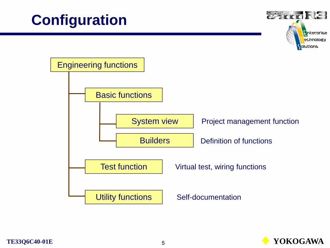
Configuration
Engineering functions
Basic functions
System view
Builders
Test function
Utility functions Self-documentation
Virtual test, wiring functions
Definition of functions
Project management function

6 YOKOGAWATE33Q6C40-01E
Concept of DCS Builder
TIC101PID
FIC101PID
FCS
HIS
Function block
definition
Control drawing builder
Process I/O assignment
Operation/monitoring
function definition
IOM definition builder
Graphic builder

7 YOKOGAWATE33Q6C40-01E
Engineering Environment
V net
ooo
FCS
HISEngineering database
(Current project)
System configuration, operation and monitoring windows and so on are created and edited by the builder.
Engineering environment
Engineering work with builder
FCS load
HIS load
Download the created system configuration, the operation and monitoring windows and so on to the system.

8 YOKOGAWATE33Q6C40-01E
Engineering Environments
V net
Ethernet
ooo
Standard FCS
ENG/HIS
Engineering functions andvirtual test functions
Engineering environment outside a target system*.
Engineering data Engineering data
* Target system: The hardware, which is used in plant operation.
Engineering environment in a target system.
ENG/HIS

9 YOKOGAWATE33Q6C40-01E
Engineering Environment
V net
ooo
Standard FCS
Operation/monitoringfunctions
Engineering functions
Engineering data Minimum system
Engineering functions and operation and monitoring functions within a single HIS.
ENG/HIS

10 YOKOGAWATE33Q6C40-01E
Engineering Environment
V net
Ethernet
ooo
Standard FCS
HIS
Engineering functions
Independent engineering functions.
Engineering data
Operation/monitoringfunctionsENG/HIS

11 YOKOGAWATE33Q6C40-01E
Engineering Environment
V net
Ethernet
PC
Engineering data
Concurrent engineering via network.
HIS
Concurrent engineering via network
Engineers can execute engineering works using a single engineering database simultaneously.
Engineering functions
ooo
Standard FCS
Operation/monitoringfunctionsENG/HIS

12 YOKOGAWATE33Q6C40-01E
Engineering Environment
V net
Merging engineering data.
PC
Engineering data merging
Engineering dataEngineering data
Engineering functions
The engineering data created with another PC can be easily merged.
Operation/monitoringfunctions
ooo
Standard FCS
ENG/HIS

13 YOKOGAWATE33Q6C40-01E
Engineering Environment in TC
V net
FCS 0101
Ethernet
HIS 0124 HIS 0123
Left-hand side HIS is HIS0124, which has an engineering database.
Engineering data
HIS0124 should be activated before HIS0123.
Right-hand side HIS is HIS0123, which has the function of system creation but no engineering database. HIS0123 shares the database with HIS0124.

14 YOKOGAWATE33Q6C40-01E
Engineering Procedures
CS1000/3000 Engineering Course Textbook
PART-ENG 2
Engineering Procedures

15 YOKOGAWATE33Q6C40-01E
Engineering Flow
Specification review
Basic design
System generation
Unit and connected test
Integration test
Start-up
Maintenance
Expansion & modification
Detailed design
Control method, necessary hardware and so on
Regulatory control, sequential control design
System generation with builders
Virtual test using operation and monitoring windows
Target test with FCS
Hardware installation and loop check
Engineering data backup and, hardware check
Expansion and modification of control functions
New engineering

16 YOKOGAWATE33Q6C40-01E
Engineering Work Flow
Project creation
Common item definition
Control function definition
Operation/monitoring function definition
Virtual test execution
Defined function download
HIS Setup functions
Target test execution
Parameter save
Project save
Documentation of project
Included in the engineering course.
HIS
FCS
Done in the fundamental course.

17 YOKOGAWATE33Q6C40-01E
Confirmation of Project
Project for the target system
Confirming project folder
Creating FCS folder
Creating HIS folder
Confirm that the project has been created for the target system.
Confirm that the FCS and the HIS folders have been created in the project folder.
If the FCS and HIS folders necessary for the target system are not found, create these folders.

18 YOKOGAWATE33Q6C40-01E
Defining Common Items
Defining the items commonly used by the project.
Saved in the COMMON folder. In most cases, default values are acceptable.
Alarm priority
Alarm status label
Alarm processing table
Block status
Plant hierarchy
Engineering unit symbol
Switch position label
Operation mark
Status change
User security
Alarm related builders may be discussed in PART-B, Function BlockItems in yellow boxes will be defined in the exercise.

19 YOKOGAWATE33Q6C40-01E
Defining Control Functions
FCS property
FCS common items
I/O module definition
Creation of regulatory control functions
Creation of sequential control functions
Unit management
Start conditions, digital filter coefficients and so on.
I/O module hardware definition.
Function block creation and wiring, and detailed definition.
Sequential control functions and soft I/O definition.
Items in yellow boxes will be defined in the exercise.
FCS type, database type and so on.

20 YOKOGAWATE33Q6C40-01E
Defines the operation and monitoring functions.
Some functions such as the functions related to printers, should be defined with HIS Setup.
The HIS setup functions are also able to temporarily define functions supporting operations such as function keys.
HIS constants
Function keys
Scheduler
Trend
Sequence messages
Graphic windows
Help messages
Plant hierarchy
Panel set
Operation & Monitoring Functions
Items in yellow boxes will be defined in the exercise.

21 YOKOGAWATE33Q6C40-01E
Control functions created by a user with builders are tested.
Virtual test uses the FCS simulator for the actual FSC and executes the test on the HIS.
A wiring files are created automatically at the startup stage of the test function. The created wiring may be used intact.
Control function creation
Creation of operation windows
Test function startup
Wiring confirmation
Confirmation of operation
Control function creation and its test
Virtual Test Execution

22 YOKOGAWATE33Q6C40-01E
Project common download
Download FCS data
Download HIS data
Engineering data defined by a user with builders are downloaded to FCS and HIS.
The projects using a gateway and/or a bus converter, the configuration files are also downloaded.
Downloading of Created Functions
23 YOKOGAWATE33Q6C40-01E
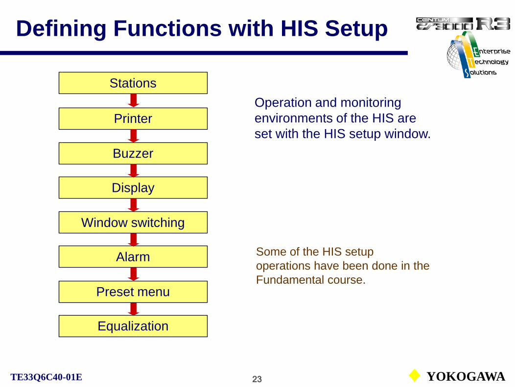
Operation and monitoring environments of the HIS are set with the HIS setup window.
Stations
Printer
Buzzer
Display
Window switching
Alarm
Preset menu
Equalization
Defining Functions with HIS Setup
Some of the HIS setup operations have been done in the Fundamental course.

24 YOKOGAWATE33Q6C40-01E
Control functions created by a user with builders are tested.
The engineering database is downloaded to the FCS and tested. When the I/O test instruments such as I/O modules, signal generators are not used, the FCS I/O signals are simulated by I/O disconnection and automatic wiring.
Startup of the test function is not necessary, if the actual I/O can be used.
Test function startup
I/O disconnection
Automatic wiring
Wiring download
Confirmation of operation
Target test using wiring functions
Execution of Target Test

25 YOKOGAWATE33Q6C40-01E
Setting tuning parameters
Saving tuning parameters
Save the tuning parameters set on function blocks tuned during the trial operation.
If the FCS offline download is executed without the parameter save, default parameters are downloaded to the function blocks.
Tuning Parameter Save

26 YOKOGAWATE33Q6C40-01E
Saving of Project
Saving tuning parameters
Backup of folders
Preparing for the data evaporation caused by hardware errors such as HDD crush, project data are saved in external memories.
Copying the project folder and the following folders backups the whole engineering data.
The database related to the HIS, set by the HIS Setup functions, is not included in the project folder. For the perfect recovery of HIS, the backup of the HIS Setup data is necessary too.

27 YOKOGAWATE33Q6C40-01E
Self-Documentation
For the system maintenance or expansion and modification in the future, the data defined with builders can be printed or output to PDF files*.
* PDF file output is supported by R3.02 and later release. It needs Acrobat in addition.
Project selection
Startup of self-document
Header editing etc
Selection of printing range
Documents output
Output self-document

28 YOKOGAWATE33Q6C40-01E
Project
CS1000/3000 Engineering Course Textbook
PART-ENG 3
Project

29 YOKOGAWATE33Q6C40-01E
Project
Project is the unit of managing the FCS and HIS data created by system generation functions. Builder files defined by the system generation functions are managed in the unit of project.
FCS download
Current project
Default project
User defined project
Automatically created new project at initial startup.
The unique project, which exists in FCS.
Used for testing and debugging. More than one project can be created.
The engineering data meet with the system in operation.

30 YOKOGAWATE33Q6C40-01E
Default Project
• Default Project:After the system installation, the project created at the first startup of the System View is called default project.
Features:1) Downloadable to FCS.2) Virtual test is possible with FCS simulator.3) Downloadable to HIS.4) Offline download to FCS in the target system is possible.

31 YOKOGAWATE33Q6C40-01E
Current Project
• Current Project:If the offline download to any FCS in the default project is executed, the attribute of the project changes from default to current. And thenthe online engineering is enabled.
Features:1) Multiple projects cannot be created.2) Target test is possible.3) Downloadable to HIS. 4) Offline download to FCS in the target system is possible.

32 YOKOGAWATE33Q6C40-01E
User Defined Project
• User Defined Project:A copied current project for editing or a newly created project is called a user defined project.Download the project to FCS is disabled. The project is used forengineering with the virtual test or for backup of the current project.
Features:1) Multiple projects can be created on the system view. 2) Virtual test is possible with the FCS simulator.3) Download to the FCS and the HIS in the target system is impossible.

33 YOKOGAWATE33Q6C40-01E
Current Project
ooo
FCS
Downloadable to FCS.Attribute changes on download.
Online maintenance enabled.A unique project that enables to confirm the FCS data.
Attribute changes automatically on download
A single project/system
Current project
Defaultproject
Default Project Current project
At initial installation
Ordinary system configuration
Offline download
Tuning parameter
save
Online download
Offline download

34 YOKOGAWATE33Q6C40-01E
User Defined Project
Copied current project
User defined project
User defined project
User defined project
Newly created project
Attribute change by
utility
Download to FCS is disabled.Multiple projects can be created for testing, expansion and so on.
Ordinary system configuration
Online maintenance enabled.A unique project that enables to confirm the FCS data.
A single project/system
Current project
Current project
Multiple projects/system

35 YOKOGAWATE33Q6C40-01E
Project Attribute ChangeProject attribute can be changed by the “Utility to Change Project’s Attribute”.
“Change Attribute of Project” dialog
To call “Utility to Change Project’s Attribute” dialog.

36 YOKOGAWATE33Q6C40-01E
Project Creation for Exercise
Project positionH:/CS3000/eng/BKProject/

37 YOKOGAWATE33Q6C40-01E
CS1000/3000 Engineering Course Textbook
PART-ENG 4
System Generation
System Generation

38 YOKOGAWATE33Q6C40-01E
System Generation
• Project creation• System configuration definition
• I/O module definition• Builder startup• Test function startup• Documentation
function startup• Database load• Parameter save
System View(Collective management engineering environment for CS1000/3000.)

39 YOKOGAWATE33Q6C40-01E
System Generation
Examples of functions:
• Common item definition
• I/O definition• Control functioncreation
• Operation and monitoring functionsdefinition
• Operation window definition
Builder (Generation tools of various functions)
The builder startups automatically by clicking the builder file to define or edit.
An example of a graphic builder window.

40 YOKOGAWATE33Q6C40-01E
Project Definition
Items to define: Project namePosition (The folder’s location in which database
is saved. A server or other drive can be specified.)
Project name (arbitrary)
Project positionH:/CS3000/eng/BKProject/

41 YOKOGAWATE33Q6C40-01E
Project Definition
Data to define: Manual setting of engineering units. (Default is automatic.)
Tick here for manual registration. Registration operation of the engineering units file in the COMMON folder is needed.

42 YOKOGAWATE33Q6C40-01E
Devices Composing System
After the project creation, defining the devices composing the system is required.
The following devices compose the project:
• FCS• HIS• BCV• CGW• Stations (other stations)
A hardware type for each device and a database type for the FCS should be specified. The hardware and database type cannot be changed once they were defined.

43 YOKOGAWATE33Q6C40-01E
Creation of devices composing the system.
Select the device to create or add.
Devices Composing System

44 YOKOGAWATE33Q6C40-01E
Project Common Items
The definition files common to the whole project are saved in the COMMON folder.
Most of the basic system definition files are used with default settings. Customizing is possible, if necessary.
Only the files related to the security, OpeMarkDef and UserSec should be defined beforehand.

45 YOKOGAWATE33Q6C40-01E
Engineering Unit Symbol
The engineering unit symbol is a unit symbol attached to a data value including a flow-rate and pressure, and is used on all the projects.Up to 256 engineering unit symbols can be used for one project.One engineering unit symbol can be defined with up to six alphanumeric characters.
Engineering unit symbols Nos.1 to 8 cannot be changed or deleted: Define the engineering unit symbol starting at No.9.Default values are predefined for Nos.9 to 126. No default values are predefined for the subsequent Nos.

46 YOKOGAWATE33Q6C40-01E
Switch Position LabelUp to 64 sets switch position labels can be defined. One set consists of four labels (label 1, label 2, label 3, and label 4).The label 4 character string is not displayed on the instruments. Define a unique character string for each set.
Switch position labels Nos.1 and 2 cannot be changed or deleted. Default values are predefined for Nos.3 to 13.

47 YOKOGAWATE33Q6C40-01E
Flow of User Security Check
HIS operation
HIS security check
Scope of operation and monitoring
check for the HIS
User security check
• Window operation and monitoring• Function block operation and monitoring Operation record
OperationHistory
Security check
Operation
Scope of operation and monitoring
check for a user group
Privilege levels of operation and monitoring check
for a user

48 YOKOGAWATE33Q6C40-01E
Security Overview
General-purpose Windows applications follow the security policy of Windows. The user of CENTUM is different from the user of Windows.
The following two types of policies are available in CS 1000/CS 3000.• HIS Security PolicyHIS security policy stipulates the scope of operation and monitoring allowed on the Human Interface Station. Regardless of the logon users, the operation performed to a device or to a function block data item may be restricted.• User Security PolicyUser security policy stipulates the scope of operation and monitoring for the users.Each user is restricted to operate or monitor a certain scope of devices and function block data items.
The scope of operation and monitoring permitted for an operator is determined by a combination of HIS security and user securitysettings.

49 YOKOGAWATE33Q6C40-01E
HIS Security
The security level setting means to select either monitoring only machine or monitoring and operation machine (default).
The security level regarding operation and monitoring as well as the operation and monitoring scope can be set for the HIS itself. The HIS security check has a precedence over the user security check. The operation and monitoring scope of the HIS is unrelated with the operation and monitoring scope set for each user group.

50 YOKOGAWATE33Q6C40-01E
HIS Security Definition
The HIS Attribute (security level) and HIS Security (operation and monitoring range) settings in the HIS Constant Builder.
HIS attributes setting. HIS security setting.
See IM33S01B30-01E PART-F Engineering, F9.2 User Group.

51 YOKOGAWATE33Q6C40-01E
User Security
User name: User recognitionPassword: User identificationUser group: Monitoring and operation scopePrivilege level: Monitoring and operation authority
The operations performed by the user are held as the operation record. The operation record can be confirmed by the historical message report.
The operators performing the operation and monitoring functions are classified based on their privilege level (authority). This classification is called user.
The following attributes are assigned to each user:

52 YOKOGAWATE33Q6C40-01E
User Group
The range is set by the plant name. If the plant name is not used, set by the station name and the control drawing.
The following attributes are assigned to each user group:
• User group name: User group recognition• Monitoring scope: Monitoring range• Operation and monitoring scope: Operation and monitoring range• Windows scope: Window names for operation and monitoring• Acknowledgement: Acknowledgment range • Process message receiving: Monitoring range of the generated messages
The users are classified into groups based on their operation and monitoring scopes. This classification is called user group.

53 YOKOGAWATE33Q6C40-01E
Concepts of Scope and Privilege
Operation & monitoring scope of users, OPS*-A in Group-AB using HIS0124 and their privileges.
Operation & monitoring scope of HIS0124.
EquipmentA
Users in Group-AB:OPS1-A: OPS2-A: OPS3-A:
Whole Plant
EquipmentB
EquipmentC
EquipmentD
EquipmentE
Operation & monitoring scope of user Group-AB.
MonitoringOperation and monitoringOperation, monitoring and maintenance

54 YOKOGAWATE33Q6C40-01E
User Registration
UserSec builder registers user names. The UserSec builder also specifies user groups belong to, privilege levels and so on.
Registration of user name, user group and privilege levels.
CENTUM users should be registered in the window above. User and user group for MS Windows are different from the CENTUM users.
Detailed setting items:With detailed setting items builder, operation and monitoring range can be specified.

55 YOKOGAWATE33Q6C40-01E
User Group Registration
Default user groups and their rage setting.
User group registration and their rage setting.
UserSec builder registers user group names. The UserSec builder also specifies ranges of operation and monitoring, acknowledgement and so on.

56 YOKOGAWATE33Q6C40-01E
Privilege Levels
The following default privilege levels are available (security level 4).
*1: Maintenance means the engineering work such as initiation of the builder.
The users’ operation and monitoring rights on HIS are defined according to privilege levels.For each window, operation and monitoring rights can be defined. Whether the user with a certain privilege level is permitted to operate the specified data item can also be defined.

57 YOKOGAWATE33Q6C40-01E
Privilege Levels and Ranges
Monitoring and operation ranges and so on for each user can be customized with the detailed setting items builder.
User privilege levels can be customized (U1 to U7.)
Window authorities (Access levels).
Registration of monitoring range for each user privilege.
Detailed setting items.
Operation and monitoring range customizing sheets for each user privilege.

58 YOKOGAWATE33Q6C40-01E
Window Authorities Definition
Definition of window operation and monitoring authority.
The authorities on windows can be defined in the “Create New Window” dialog.
59 YOKOGAWATE33Q6C40-01E
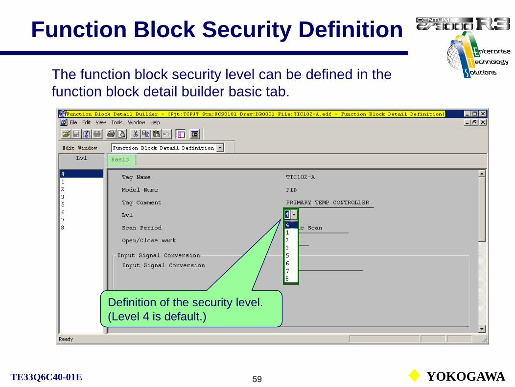
Function Block Security Definition
Definition of the security level.(Level 4 is default.)
The function block security level can be defined in the function block detail builder basic tab.

60 YOKOGAWATE33Q6C40-01E
Mode Selection Key
In the case of the operation key When the engineering key is selected.Changes between The key can be switched
the ON, OFF positions. to any position.
The following two mode selection keys are used to switch the security level:
When the HIS is connected with an operation keyboard, the privilege level of the user may be changed temporarily using the mode selection key on the keyboard. The privilege level changed on the keyboard has higher priority than the level set in the user-in dialog box.
• Operation key (Privilege level S2)The key can be switched between the ON and OFF positions only.• Engineering key (Privilege level S3)The key can be switched to any position.

61 YOKOGAWATE33Q6C40-01E
Operation MarkAn operation mark attached on an instrument faceplate temporarily restricts the user privilege levels of operation and monitoring. Operation mark definition builder defines a tag label, a tag level and so on.
For each operation mark, a tag level (a privilege level) can be assigned.
For each operation mark, a privilege level for the installation or removal of the operation mark can be assigned.
62 YOKOGAWATE33Q6C40-01E
Common Items
The following items are common for engineering functions:
• NameSystem generation function names basic elements such as function blocks, windows, and so on.
• CommentSystem generation function adds comments for the explanation to function blocks, windows and so on, if necessary.
• Type of filesSystem generation function handles three-type of files; Builder file, Save As file and Working file.
• Configuration of folders and filesEngineering data are configured with a unit of project.
• External fileThe data defined by the builder can be exported to an external file with a different format.
63 YOKOGAWATE33Q6C40-01E
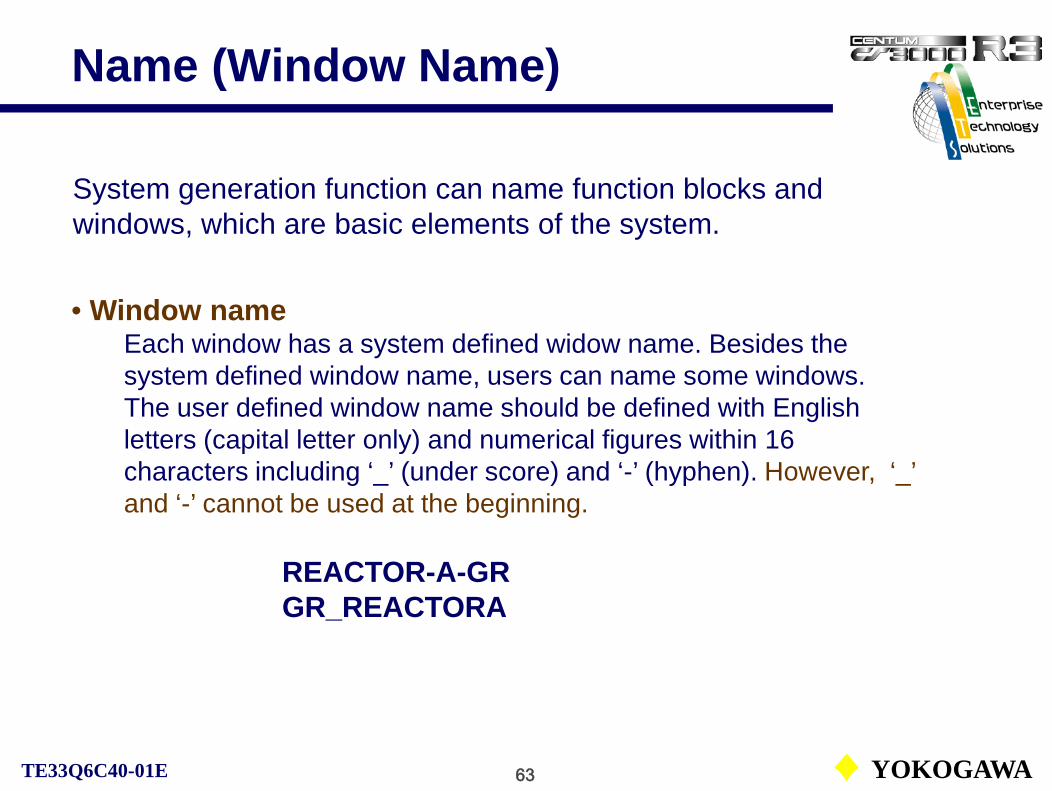
Name (Window Name)
System generation function can name function blocks and windows, which are basic elements of the system.
• Window nameEach window has a system defined widow name. Besides the system defined window name, users can name some windows. The user defined window name should be defined with English letters (capital letter only) and numerical figures within 16 characters including ‘_’ (under score) and ‘-’ (hyphen). However, ‘_’ and ‘-’ cannot be used at the beginning.
REACTOR-A-GRGR_REACTORA

64 YOKOGAWATE33Q6C40-01E
• Tag name
The names, which are assigned to identify function blocks, elements and so on in the control stations are called tag names. There are two kinds of the tag names; system tag names and user defined tag names.
The system tag name consists of % [element code] [element number] S [domain number] [station number].
%SW1024S0102
The user defined tag name can be defined with English letters (capital letters only) and numerical figures including ‘_’ (underscore) and ‘-’ (hyphen) up to 16 characters. But ‘_’ and ‘-’ cannot be used at the beginning.
FIC1035, TIC100-A
Name (Tag Name)

65 YOKOGAWATE33Q6C40-01E
The builder configuring operation and monitoring functions, control functions has three types of files.
• Builder fileThe master file handled by the builder is called a builder file. The file extension is .edf.When the created file is saved with Save command or downloaded with Download command without any error, the file becomes the builder file.
• Save-As fileWhen the defined contents by the builder have errors, the file cannot be saved with Save command. The file is saved with Save As command. The file extension is .sva.The SVA file may be imported to the builder for editing.
Type of Files
Data import and export also use SVA files.

66 YOKOGAWATE33Q6C40-01E
Type of Files• Working file
During editing of a builder file, the file can be saved as a working file, even the file has errors. The file extension is .wkf. If a working file is saved, a builder file and a working file exist. Only the builder file can be edited. When the builder file is called up, the working file may be imported into the builder file. After editing the builder file is saved or downloaded without errors, the working file is deleted.
The working file can only be imported by the corresponding builder file.
A builder and a working file of DR0007.
Working file selection dialog.
67 YOKOGAWATE33Q6C40-01E
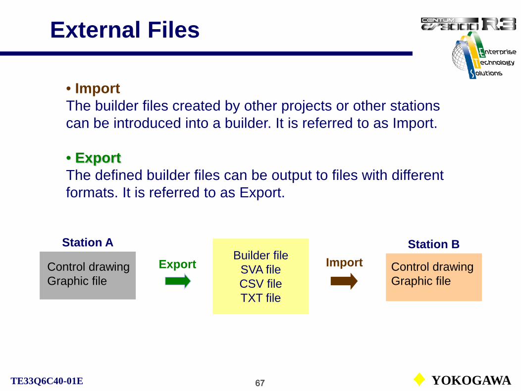
• ImportThe builder files created by other projects or other stations can be introduced into a builder. It is referred to as Import.
• ExportThe defined builder files can be output to files with different formats. It is referred to as Export.
Control drawingGraphic file
Station A
ExportBuilder file
SVA fileCSV fileTXT file
ImportStation B
External Files
Control drawingGraphic file

68 YOKOGAWATE33Q6C40-01E
Test Function
CS1000/3000 Engineering Course Textbook
PART-ENG 5
Test Function

69 YOKOGAWATE33Q6C40-01E
With I/O devices
Without I/O devices
Types of test
Target test
Types of Test
The test function is the tool to test the data and functions created by a user with engineering functions.
Types of tests are automatically selected by the test function based on the project’s attribute.
Current project (FCS downloaded)
User defined project/default project (FCS not downloaded)
Virtual test
Use wiring function
See IM33S04N10-01E PART-A Functions, A1 What is Test Function?

70 YOKOGAWATE33Q6C40-01E
V net
ooo
Standard FCS
The target test uses the actual FCS for testing.The test can be executed either using I/O modules or wiring functions without I/O modules.
HIS
I/O disconnection(wiring function)
FIC100PID
I/O simulator
1st order lag, dead time or other
functions
IN OUT
Target Test

71 YOKOGAWATE33Q6C40-01E
Virtual Test
A single PC can execute the test without CS equipment.
Virtual test functionCENTUM CS
1000/3000 system
One PC executes test
Test function
System generation
Multiple FCS
FCS
HIS
Operation and
monitoring

72 YOKOGAWATE33Q6C40-01E
V net
ooo
FCS
HIS
The virtual test functions executes the test using a FCS simulator for a real FCS. The FCS simulator functions on a PC.
Virtual test function
Operation /monitoring
FCSsimulator
HIS or PC
Creation and testing of the applications do not require a special hardware.A general purpose PC performs engineering and testing anywhere.
Disconnection from the control network
Virtual Test Functions
73 YOKOGAWATE33Q6C40-01E
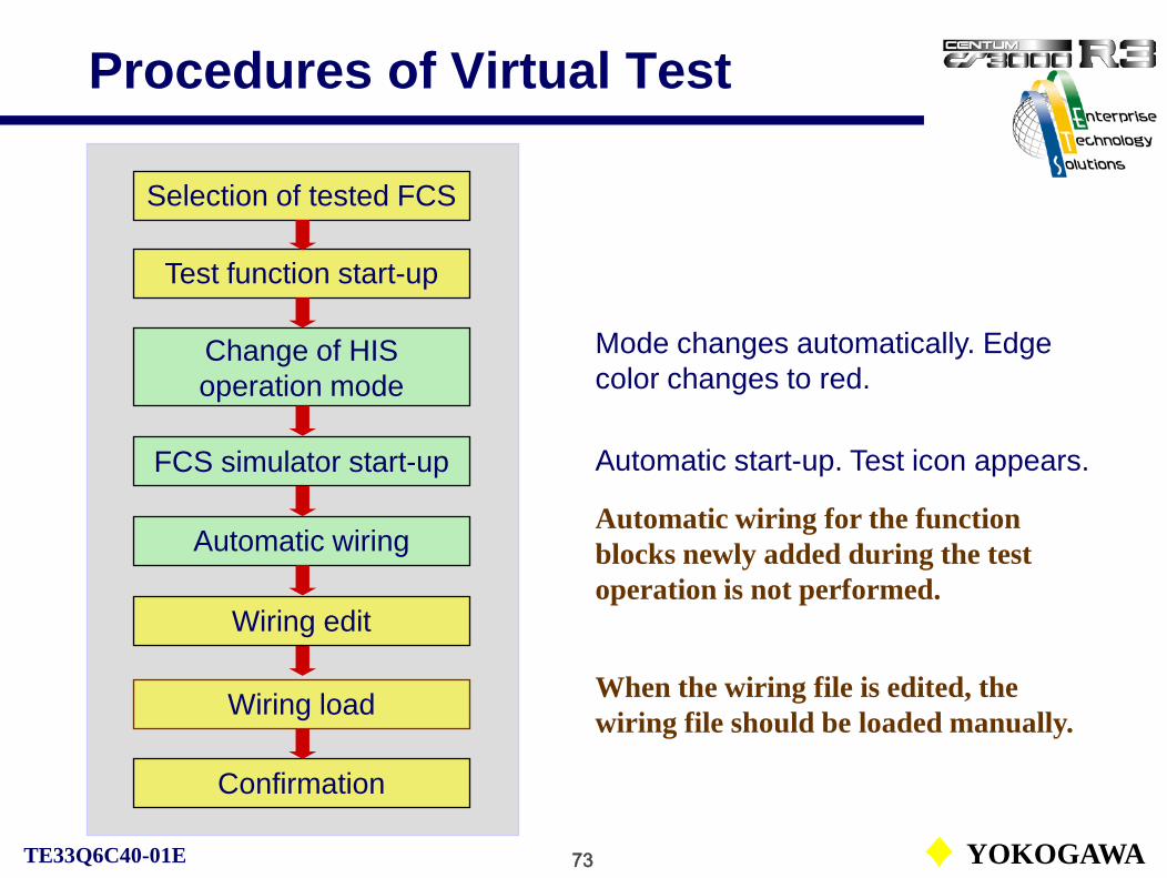
Procedures of Virtual Test
Mode changes automatically. Edge color changes to red.
Change of HIS operation mode
FCS simulator start-up
Automatic wiring
Wiring load
Confirmation
Selection of tested FCS
Test function start-up
Wiring edit
Automatic start-up. Test icon appears.
When the wiring file is edited, the wiring file should be loaded manually.
Automatic wiring for the function blocks newly added during the test operation is not performed.

74 YOKOGAWATE33Q6C40-01E
Wiring Function
The wiring function executes a virtual wiring between process I/O module terminals.This function enables the test of the control functions in the FCS or the FCS simulator, not using real I/O devices.
To operate the wiring function, downloading of a wiring definition and wiring data is needed.
See IM33S04N10-01E PART-A Functions, A5 Wiring Edit.
ooo
FCS
Output moduleA(+)B(-)
Output modules are to be short-circuited in the I/O disconnected target test to avoid the output open state (OOP).

75 YOKOGAWATE33Q6C40-01E
Wiring Editing FunctionThe wiring editor enables to edit the connections between I/O terminals, the delay or lag time constants and so on.
The wiring file is created automatically and downloaded to the created control drawing.
Wirings are performed automatically for the function blocks having I/O terminals.

76 YOKOGAWATE33Q6C40-01E
Concepts of Wiring FunctionThe wiring function makes connections virtually between the process I/Os not using the actual I/Os. (I/O disconnection.)
FCS control functions
Virtual data area(Contents of the wiring file)Lag or delay functions can be used as a simplified process simulation tool.
TIC101OUT
FIC101
SETIN
OUT
I/O image on FCS memory
Lag/delayfunction
Lag/delayfunction
IN
PID
PID

77 YOKOGAWATE33Q6C40-01E
Download Function
CS1000/3000 Engineering Course Textbook
PART-ENG 6
Download Function

78 YOKOGAWATE33Q6C40-01E
System DownloadDifference between the HIS download and the FCS download.
FCS databaseBlock configuration,
I/O configuration
HIS databaseWindow configuration,
messages
HIS function
download
FCS
System viewData are transferred to memory by the equalize function
At the next window switching, revised data becomes effective
HIS
FCS function
download
Data transmission to an HDD
Write on a main memory
At the next scanning period, revised data becomes effective.

79 YOKOGAWATE33Q6C40-01E
FCS Download
Offline download
The offline download transfers all FCS related engineering data to the FCS after stopping it.
The FCS download transfers the created and/or edited database to the FCS.
Online download
The online download transfers the difference between the created FCS database and the existing FCS database in the project without stopping the FCS.
Some databases such as FCS constants cannot be online downloaded.

80 YOKOGAWATE33Q6C40-01E
Offline Download
Control function databaseFunction block configuration,
I/O configuration
Tuning parameter database
Created control function database and automatically created default parameters.
Control stationEngineering database
Offline download operation.
Offline download Tuning parameter
database
In FCS offline downloading, a message box prompting for saving tuning parameters of the selected FCS appears.
Control function databaseFunction block configuration,
I/O configuration

81 YOKOGAWATE33Q6C40-01E
Tuning Parameter Save
Parameters tuned by operators and functions
Tuning parameter
save
Tuning parameter save operation.
Tuning parameter database
Engineering database Control station
Tuning parameter database
If the tuning parameters are not saved, the default values of the tuning parameters when each function block is created or the parameters saved before previous downloading will be downloaded.
Control function databaseFunction block configuration,
I/O configuration
Control function databaseFunction block configuration,
I/O configuration

82 YOKOGAWATE33Q6C40-01E
Online Download
The difference between the edited control function database and the control station (FCS) database is downloaded.
Online download
Online download operation.
Tuning parameter database
Engineering database Control station
Tuning parameter database
Control function databaseFunction block configuration,
I/O configuration
Control function databaseFunction block configuration,
I/O configuration

83 YOKOGAWATE33Q6C40-01E
Offline / Online Download
Difference of control function
database
Scope of offline
download
Operation difference between the offline download and the online download.
Tuning parameter database
Engineering database
Scope of online
download
Tuning parameter
save
Control station
Tuning parameter database
Offline download
Online download
Parameters changed by engineers and functions
Control function databaseFunction block configuration,
I/O configuration
Control function databaseFunction block configuration,
I/O configuration

84 YOKOGAWATE33Q6C40-01E
System Download
Project common download, IOM download, HIS download and FCS offline download can be executed from System View.
Selected FCS database is downloaded
See IM33S01B30-01E PART-F Engineering, F1.1.5 Load Menu of System View.

85 YOKOGAWATE33Q6C40-01E
System Download
In the current project, as the builder file save and the online download are executed at the same time, ‘Download’ is indicated on the menu.
As the online download is impossible in a user project, ‘Download’ is not shown on the menu. After editing, execute ‘Save’.

1 YOKOGAWATE33Q4T30-01E
CS1000/3000 (R3.04)
Fundamental Course TextbookTE33Q4T30-01E

2 YOKOGAWATE33Q4T30-01E
CS1000/3000 Overview
A-1 Process Control Devices
A-2 System Overview
CS1000/3000 Fundamental Course TextbookPART-A CS1000/CS3000 Overview
3 YOKOGAWATE33Q4T30-01E
CS1000/3000 Fundamental Course Textbook
A-1 Process Control Devices
01. Process Control Basic
02. Process Control Systems
03. Types of Control Systems
Process Control Devices
4 YOKOGAWATE33Q4T30-01E
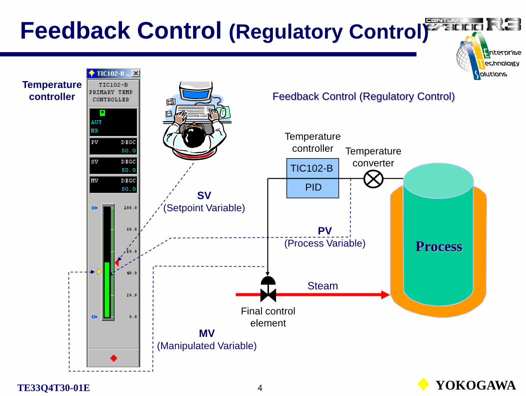
Feedback Control (Regulatory Control)
TIC102-B
PID
Steam
PV(Process Variable)
MV(Manipulated Variable)
SV(Setpoint Variable)
Process
Feedback Control (Regulatory Control)
Temperature converter
Final control element
Temperature controller
Temperature controller

5 YOKOGAWATE33Q4T30-01E
Sequential Control
LI001
PVI
V2:Outflow Valve
V1:Inflow Valve
Start
V1 Open
Inflow
LI001“HI”
V1 Close
V2 Open
Outflow
HI
LO
Outflow
Inflow
Operation PanelN
N
NLI001“LO”
V2 Close
End
N
LevelIndicator

6 YOKOGAWATE33Q4T30-01E
Analog Control / Digital Control
PID unit
Controller
DeviationProcess variableMVSV +
–
PV
PIDPROCESS
(including control valve )
Sensor andTransmitter
Controller
MVSV +
–
PV
Numerical Data
CPU D/A &hold
A/D
PROCESS(including control
valve )
Sensor andTransmitter
Analog ControlIn analog control, PID computation is carried out with an electric current or voltage by a hardware. It is very hard to change the control algorithm.High accuracy computations used for the advanced control are also difficult.
Analog Control
Digital ControlIn digital control, PID computation is carried out by a software. It is easy to change the control algorithm.High accuracy computations used for the advanced control are also easy.
Digital Control
Process variableDeviation

7 YOKOGAWATE33Q4T30-01E
Centralized Control System
Operator Station(monitoring and logging)
A/D I/OBuffer
MPXINPUT UNIT
MV
PV
SV SV SV
CPU(Computer)
Alarm Report
D/AI/OBuffer
MPXOUTPUT UNIT
SPC (Setpoint Control)Then the computer was used for setting optimum setpoints on individual controllers.
DDC (Direct Digital Control)And then a single computer is used to executes control computations for controlling multiple control loops.
LoggerAt the initial stage, a computer was used as a logger only for the monitoring and logging.
SPC(Setpoint Control)

8 YOKOGAWATE33Q4T30-01E
Distributed Control System (1)
I/O Image
Communication module
Output moduleInput module
Analog outputAnalog input
Isolator
CPU Data/Communicationprocessing
V/Iconversion
D/A conversion
CPU Data/Communicationprocessing
A/D conversion
Signal conversion
Isolator
The concept of I/O processing of the distributed control system.
Each signal conversion module in the node (I/O processing unit) has a CPU.
I/O signal processing is distributed.
Node
9 YOKOGAWATE33Q4T30-01E
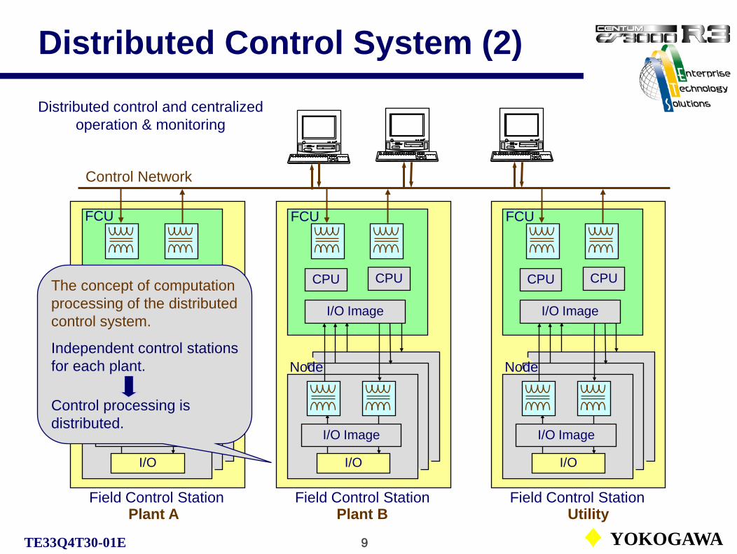
Distributed Control System (2)
Control Network
Plant A
Distributed control and centralized operation & monitoring
CPU
Field Control Station
I/O
CPU
Plant B Utility
I/O Image
I/O Image
Node
CPU
Field Control Station
I/O
CPU
I/O Image
I/O Image
Node
Field Control Station
CPU
I/O
FCU FCU
CPU
FCU
I/O Image
I/O Image
Node
The concept of computation processing of the distributed control system.
Independent control stations for each plant.
Control processing is distributed.

10 YOKOGAWATE33Q4T30-01E
System Overview
CS1000/CS3000 Fundamental Course Textbook
A-2 System Overview
01. Basic Concepts of DCS 02. System Configuration

11 YOKOGAWATE33Q4T30-01E
CENTUM CS Lineup
• CENTUM CS 3000 R3DCS based on Windows for large-scale factories The new production control system of Yokogawa. The CENTUM CS 3000 R3 features sophisticated functions and components to meet all production state requirements.
• CENTUM CS 1000 R3DCS based on Windows for small- and medium-scale factories The CENTUM CS 1000 R3 has the same architecture as CS 3000. It is specifically designed for the requirements for the middle and small scale plants.
• CENTUM CSDCS based on UNIX for large-scale factories The CENTUM CS was put on market in 1993. Since then, the CENTUM CS proudly keeps its overwhelming high reliability.

12 YOKOGAWATE33Q4T30-01E
History of DCS
Development of digital control technology and Yokogawa’s DCS.

13 YOKOGAWATE33Q4T30-01E
Position of DCS
OrderProduction plan
Production management
Production system
Customer management
Process control management
Production equipment
Total information system in manufacturing.
Order reception
Demand prediction
Business system
DCS(Production control system)

14 YOKOGAWATE33Q4T30-01E
Concepts of Modern DCS
Open information network
Operator/work station ( Open environment )
Real-time control network
Advanced control station ( RISC processor )
Field bus
Intelligent devices (with basic control functions)
15 YOKOGAWATE33Q4T30-01E
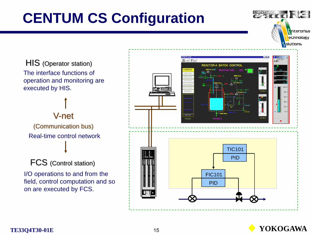
CENTUM CS Configuration
TIC101PID
FIC101PID
ooo
FCS (Control station)
HIS (Operator station)
I/O operations to and from the field, control computation and so on are executed by FCS.
The interface functions of operation and monitoring are executed by HIS.
V-net(Communication bus)
Real-time control network

16 YOKOGAWATE33Q4T30-01E
CS and Single Loop Controller
V net
YS100Single loopcontroller
Inpu
t con
vers
ion
Out
put c
onve
rsio
n
Computation
HIS
Input processing(A/D conversion)
Output processing(D/A conversion)
Control computationTI
C00
1
TIC
002
TIC
003
TIC
004
TIC
001
TIC
002
TIC
003
TIC
004
TIC
001
TIC
002
TIC
003
TIC
004
I/O modules
ESB or RIO bus I/O images
FCS
Node
FCU(Field Control Unit)

17 YOKOGAWATE33Q4T30-01E
Signal Flow in CS (Example)
TIC100
PID
Process variable PVEngineering data
Ex. 350 ºC
A/D
-5.9 – 48.8mVAnalog data
I/O images
Internal RIO/ESB bus communication
Field device connection(Hard-wiring)
FIC100
PID
-200 – 1200 ºCDigital data
Engineering dataEx. 6.5 M3/M SETOUT
Process variable PVEngineering data
Ex. 5.2 M3/M
Terminal connection(Soft-wiring)
OUT
IN
IN
A/D D/A
4 - 20mAAnalog data
4 - 20mAAnalog data
0 – 100 %Digital data
-200 – 1200 ºCType K TC
0 - 10.0 M3/M
-200 – 1200 ºCDigital data
0 – 100 %Digital data
0 – 100%Digital data
0 – 100%Digital data
I/O (PIO) connection(Soft-wiring)
Measuring range is set by each function block.

18 YOKOGAWATE33Q4T30-01E
System Function Concept
Subsystem(PLC, DARWIN etc)
Production Management (MES*, PIM**)
Field Devices (Production Plant)
CENTUM CS1000/CS3000
*MES:Manufacturing Execution System
**PIM:Plant Information Management
Process I/O,Subsystem I/O,Fieldbus I/O etc.
Ethernet communication
*Can be executed by HIS.
Operation & MonitoringFunction (HIS)
V-net/VL-net communication
Control Function (FCS)
Engineering Function* (ENG)

19 YOKOGAWATE33Q4T30-01E
Features of Operation & Monitoring Functions
Features of HIS operation and monitoring functions:
■ Keeping abreast of the operation environments for the modern technologyThe human-machine interface (HMI) uses a generic PC and Windows 2000 or Windows XP. This allows to use the most modern PC as a hardware and to keep abreast of the development of Windows as software.
■ Integration of the PC and DCSHIS operation is done by the mouse as the operation for the general applications for Windows. Displayed diagrams and operation methods are the same as the conventional DCS. It allows to accustom to the operation environments easy.
■ Many-sided operation environments for plant operating conditionsThe maximum of 4000 user-defined windows are provides for the CENTUM CS 3000*. It allows to create display windows freely for the operation environments. The plant can be operated not only by an optional operation keyboard or touch panels as in the conventional DCS, but also by the mouse as in the office PC.
Maximum 1000 for CENTUM CS 1000.

20 YOKOGAWATE33Q4T30-01E
Features of Control Functions
Features of the control functions of FCS:
■ High reliability controlThe highly reliable dual-redundant controller used for many years is employed to realize non-stop control.
■ The optimum control stations selectable for a scale or conditions of plantThe standard (centralized) type that controls many distributed I/O points by a control unit or the compact (distributed) type that controls by distributing the control units in a plant, which enables high speed communications by distributing the load of control.These control stations can be used up to *256 for a system. It enables to cope with from a small scale plant to a very large scale plant. (* 24 stations for CENTUM 1000)
■ Control functions that easily realizes the various applications for the plantBy not only a standard PID control and a sequential control function, but also a batch control function based on the ISA S88 standard, the control functions can cope with from a mass production to a flexible production (many-kinds and small-quantity).
■ Coping with intelligent field devicesThe control load can be distributed to a field side with the FOUNDATION fieldbus. This increases an operation efficiency of the control stations that enables the advanced controls. The parameters in devices regardless of vendors can be read in the DCS.

21 YOKOGAWATE33Q4T30-01E
Features of Engineering Functions
Features of the engineering functions of ENG:
■ Easy creation of functionsThe system is created with the software on a generic PC in interactive way and with the minimum settings. Engineering data can be reused and edited with general Windows software. This enables standardization and parallel engineering and leads to a higher quality and a reduction of engineering time. The simulator that has the same data base as the actual controller can be operated on a generic PC. It realizes the environments of the actual operations (virtual test function). A single loop test without an actual controller or an experimental system configuration test is enabled.
■ On-line documentationAll of the users manuals is electronic documents and they are provided with CD-ROM’s. The file format is PDF (Portable Document Format) that is the standard electronic documents on the internet.These electronic documents can be read not only in sequence as in the usual documents, but also can be read and printed on demand during engineering.

22 YOKOGAWATE33Q4T30-01E
System Configuration (CS1000)
VL-net
Desktop type HISEthernet(Optional)
Console type HIS
No. of monitoring tags: 8,000No. of stations: 24No. of domain: 1No. of HIS: Max. 8VL-net extension: 185 m*
Compact type PFCS
* Extension length is for 10Base2 cable.

23 YOKOGAWATE33Q4T30-01E
System Configuration (CS3000 small)
V-net
Ethernet
CGW
Communication gateway unit
BCVBus Converter
No. of monitoring tags: 8,000No. of stations: 256No. of domains: 16No. of stations per domain: 64No. of HIS: Max. 16V-net extension: 500m*
Desktop type HISConsole type HIS
Compact type FFCS-S(for FIO)
* Extension length is for 10Base5 cable.
Supervisory computer
CS3000 in another domain
or XL/μXL
The BCV connects the stations on the V/VL-net on another domain. Other non-V net systems manufactured by Yokogawa may be connected via BCV.
Out of the system

24 YOKOGAWATE33Q4T30-01E
System Configuration (CS3000)
V-net
Ethernet
BCV
Bus converter
(Sub-system)
ooo
ooo
CGW
Console type HIS Desktop type HIS
No. of monitoring tags: 100,000(Expandable up to 1,000,000)No. of stations: 256No. of domains: 16No. of stations per domain: 64No. of HIS: Max. 16V-net extension: 500m*
Compact TypeSFCS
Standard FCS(for RIO)
Standard FCS(for FIO)
* Extension length is for 10Base5 cable.
Supervisory computer
Communication gateway unit
CS3000 in another domain
or XL/μXL
Out of the system

25 YOKOGAWATE33Q4T30-01E
Engineering Environment in TC
VL net
FCS 0101(PFCS)
Ethernet
HIS 0124 HIS 0123
Left-hand side HIS is HIS0124, which has an engineering database. (Use Reactor A control system.)
Engineering data
HIS0124 should be activated before HIS0123.
Right-hand side HIS is HIS0123, which has no engineering database. HIS0123 shares the database with HIS0124. (Use Reactor B control system.)

26 YOKOGAWATE33Q4T30-01E
Sub-system Integration
The subsystem communication function enables CENTUM to use the data of PLC’s, recorders, measuring systems as the data from process I/O.
OPC* Server
Subsystem
Desktop type HIS Ethernet
Subsystem
Subsystem communication network
Subsystem communication network
Subsystem communication
module
Compact TypeFCS
V-net
General-purpose PC
General-purpose subsystem gateway
GSGW(OPC client)
* OPC: OLE for Process Control

27 YOKOGAWATE33Q4T30-01E
Remote Desktop Function
V-net
HIS LAN
Internet / Intranet
LFCS KFCS
ooo The remote desktop function of Windows XP Professional enables to use the functions of CENTUM CS 3000 from the remote location. By logging on the host machine from a client machine, the client machine can execute operation and monitoring or builder functions. It is also possible to log on the host machine via internet.
PC

1 YOKOGAWATE33Q4T30-01E
Operation & Monitoring Station (HIS)
Solid Style Console HIS
Desk Top HIS
Open Style Console HIS
CS1000/3000 Fundamental Course TextbookPART-B Operation and Monitoring Station
B-1 Operation and Monitoring Common ItemsB-2 System Message and Navigator WindowsB-3 Standard Operation and Monitoring Windows

2 YOKOGAWATE33Q4T30-01E 2 YOKOGAWA
Common Items
01. Operation and Monitoring Station (HIS)02. Configuration of Operation and Monitoring Stations03. HIS Desktop
Window ModeOperational Environment of Desktop
04. Window Size05. Window Name06. Window Hierarchy07. Window Closing08. Circulate Windows09. Dynamic Window Set10. Print Screen11. Rotate Windows12. Panel Set13. Operation Group
CS1000/3000 Fundamental Course TextbookB-1 Operation and Monitoring Common Items

3 YOKOGAWATE33Q4T30-01E 3 YOKOGAWA
Operation & Monitoring Station (HIS)
Solid Style Console
Drawer
Engineering Keyboard(Keyboard for PC)
Solid Style Console Kit
General Purpose PC
18” LCD / 21” CRT
Touch panel (Optional)
Operation Keyboard
Mouse (Mouse for PC)
18” LCD / 21” Upper CRT (Optional)

4 YOKOGAWATE33Q4T30-01E 4 YOKOGAWA
Operation & Monitoring Station (HIS)Open Style Console
18” Upper LCD (Optional)
Touch panel (Optional)
18” LCD
Drawer
Operation Keyboard(Optional)
Engineering Keyboard(Keyboard for PC)
Open Style Console Kit
General Purpose PC
Mouse (Mouse for PC)

5 YOKOGAWATE33Q4T30-01E 5 YOKOGAWA
Console Type HIS
Open style console
Mouse pad
Drawer for engineering
keyboard
Solid style console

6 YOKOGAWATE33Q4T30-01E 6 YOKOGAWA
General purpose PC in a console.
The merit of using general purpose PC:• The latest hardware models are available.• Easy hardware maintenance.• Out of dated hardware can be easily renewed with a minimum investment.
General Purpose PC in Console

7 YOKOGAWATE33Q4T30-01E 7 YOKOGAWA
Cards Installed in PC
Two kinds of card are installed to the PC for using the PC exclusively as the HIS.
• Control bus interface card (VF701*):The card is the V-net/VL-net system communication card, which
is installed to the PC/AT compatible PC.
* Every HIS needs this card.
** This card is not necessary for a desk top HIS, as the HIS does not use a console kit.
• Extended interface card for a Console Type HIS (AIP261**):The card connects with the interface relay board attached to the power
distribution board via a dedicated cable. It realizes functions such as communication with the operation keyboard and the touch panels, monitoring the temperature and fans, and output/input of contact signals.

8 YOKOGAWATE33Q4T30-01E 8 YOKOGAWA
Control Bus Interface Card (VF701)The control bus interface card is installed in a PCI slot of the general purpose PC. The card connects the PC to V-net/VL-net for communication.

9 YOKOGAWATE33Q4T30-01E 9 YOKOGAWA
Operation Keyboard (Optional)
Data input keys
32 Function keys
Window call keys
Scroll keys
Alarm acknowledgement keys
Confirmation keys
Mode transfer key switch Built-in speaker
Operation keyboard for single loop operation (desk top type HIS).
The operation keyboard for the console type HIS enables 8-loop operation at a time.
Cursor move keys

10 YOKOGAWATE33Q4T30-01E 10 YOKOGAWA
Operation Keyboard
Operation keys on keyboard
Overview window call
Tuning window call
Graphic window call
Process alarm window call
Operator guide
window call
Control window call
Trend window call
Process report window call
Help dialog call
Navigator window call
Upper window call
Print screen Buzzer rest
DisplayCursor move
Alarm acknowledgment
Auxiliary
Circulate
window erase
System status
overview window call
Right sibling window call
Left sibling window call

11 YOKOGAWATE33Q4T30-01E 11 YOKOGAWA
Operation Keys for Instruments
Target key: The key transfers operating data from MV to SV during manual mode (MAN).
INC key: The key increases data. 1 % of full-scale data increases every 0.2 seconds while the key is pressed. It takes 20 seconds to change 100%.
DEC key: The key decreases data. 1 % of full-scale data decreases every 0.2 seconds while the key is pressed. It takes 20 seconds to change 100%.
Speed-up key: Pressing this key together with INC key or DEC keyaccelerates the changing speed 4 times.
CAS key: The key transfers the block mode to cascade (CAS) or semi-automatic mode (SEMI). Pressing this key together with AUT key transfers to cascade mode, with MAN key transfers to semi-automatic mode.
MAN key: The key transfers the block mode to manual (MAN).
AUT key: The key transfers the block mode to automatic (AUT).

12 YOKOGAWATE33Q4T30-01E 12 YOKOGAWA
Access Mode Transfer Key Switch
Builder operation is only possible in ENG mode.

13 YOKOGAWATE33Q4T30-01E 13 YOKOGAWA
Operation and Monitoring Functions
Basic functions for operation and monitoring:
• Operation and monitoring window functions as graphic windows.
• Trend window functions to save and redisplay trends.
• Message window functions to output operator guide and alarm messages.
• Function key functions that simplify operations. (Operation keyboard)
14 YOKOGAWATE33Q4T30-01E 14 YOKOGAWA
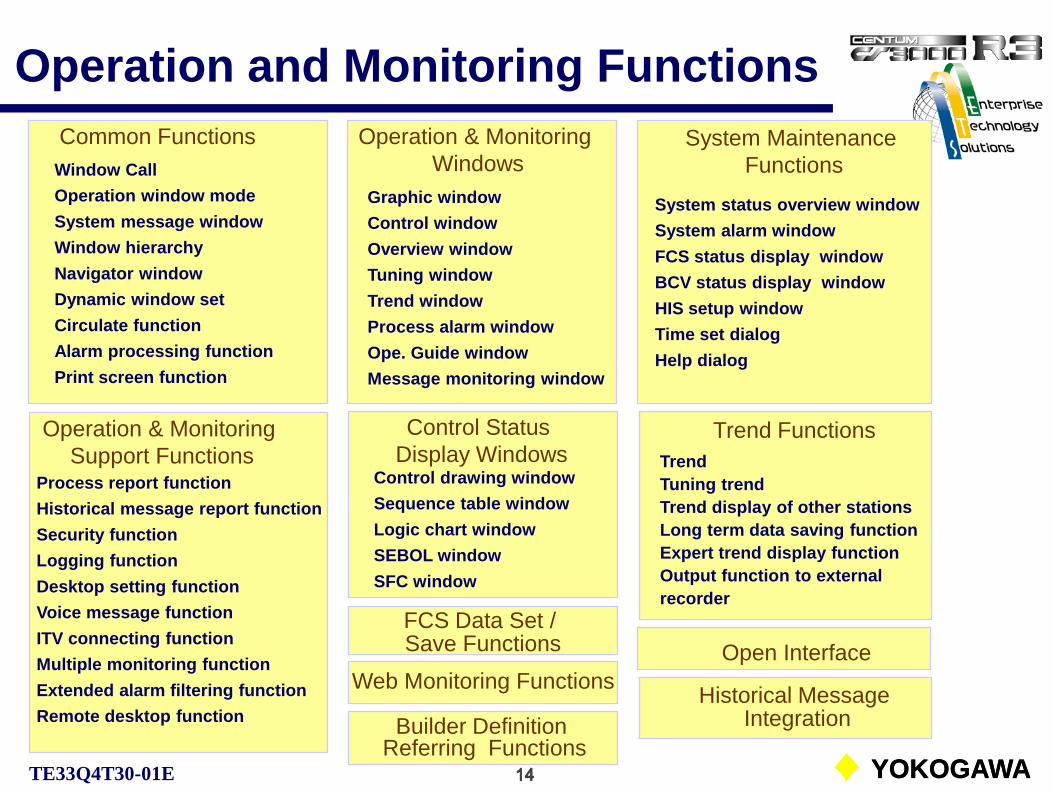
Operation and Monitoring FunctionsCommon Functions Operation & Monitoring
WindowsGraphic windowControl windowOverview windowTuning windowTrend windowProcess alarm windowOpe. Guide windowMessage monitoring window
System Maintenance Functions
System status overview windowSystem alarm windowFCS status display windowBCV status display windowHIS setup windowTime set dialogHelp dialog
Operation & Monitoring Support Functions
Process report functionHistorical message report functionSecurity functionLogging functionDesktop setting functionVoice message functionITV connecting function Multiple monitoring functionExtended alarm filtering functionRemote desktop function
Control Status Display Windows
Control drawing windowSequence table windowLogic chart windowSEBOL windowSFC window
Trend FunctionsTrendTuning trendTrend display of other stationsLong term data saving functionExpert trend display functionOutput function to external recorder
FCS Data Set / Save Functions
Web Monitoring Functions
Builder Definition Referring Functions
Open Interface
Historical Message Integration
Window CallOperation window modeSystem message windowWindow hierarchyNavigator windowDynamic window setCirculate functionAlarm processing functionPrint screen function

15 YOKOGAWATE33Q4T30-01E 15 YOKOGAWA
Capacities
The table shows the operation and monitoring function capacity.
No. of monitoring tagsNo. of user defined windowsCommunication data of graphic windowModify conditions of graphic windowModify conditions of objectNo. of faceplate display
CS1000 CS3000
No. of trend samplesNo. of trend window display pensTuning trend periodsNo. of tuning trend reserve pointsNo. of 1 sec/10 sec trend pointsNo. of 1 min to 10 min trend pointsNo. of total trendsNo. of other station trends
8,000 tags1,000 / HIS200 / windows100 / windows8 / object16 windows
100,000 tags4,000 / HIS400 / windows200 / windows8 / object16 windows
2,880 data8 pens1 second16 points256 points (2 blocks)1,024 points (8 blocks)1,024 points (8 blocks)1,024 points (8 blocks)
2,880 data8 pens1 second16 points256 points (2 blocks)2,560 points (20 blocks)6,500 points (50 blocks)3,840 points (30 blocks)

16 YOKOGAWATE33Q4T30-01E 16 YOKOGAWA
HIS Desktop
Screen modes and operation environments can be set on the HIS desktop according to operation customs and security.
When both full screen mode and CENTUM desktop are used, the display similar to CENTUM CS displays are obtained.
Screen Mode: Either full screen mode or window mode is selectable. (HIS Setup)
Operation Environment: Either Windows standard or CENTUM desktop is selectable. (HIS Utility)
Operation environment setting requires the system administrator authority and HIS restart. Environment switching during operation is not possible.

17 YOKOGAWATE33Q4T30-01E 17 YOKOGAWA
Operation Screen ModeThere two operation screen modes: Full screen mode and window mode.
Full Screen Mode:The mode that displays a window over the entire screen.
Window Mode:The mode that displays windows in the usual form of overlapped windows.

18 YOKOGAWATE33Q4T30-01E 18 YOKOGAWA
Full Screen ModeIn the full screen mode, a single operation and monitoring window, excluding a system message window, is displayed over the entire screen. That window is called a main (or primary) window and other windows are called auxiliary (or secondary) windows.
A single main window and 5 auxiliary windows can be displayed on default setting.
Window is displayed as the main window when the window is called without size specification or –SL specification.
Window is displayed as the auxiliary window when the window is called with –SM or -SC specification.

19 YOKOGAWATE33Q4T30-01E 19 YOKOGAWA
Window ModeIn the window mode, all the windows are displayed overlapped in Windows way. Maximize, minimize, close operations and so on are the same as Windows general applications.
Up to 6 operation and monitoring windows can be displayed on default setting.
Operation buttons are displayed as the windows applications.

20 YOKOGAWATE33Q4T30-01E 20 YOKOGAWA
Mode SwitchingOperation and monitoring screen mode of CS1000/CS3000 can be switched from HIS setup window.
Screen mode switching(Needs HIS restart)

21 YOKOGAWATE33Q4T30-01E 21 YOKOGAWA
HIS Desktop Operation Environment
Two desktop environments are provided for CS1000/CS3000.
● Windows Standard Environment:
The standard desktop when the Windows was installed. The standard Windows operation, such as to start general applications or to access to the network can be executed during the operation and monitoring of process.
Shutdown and restart operations of HIS are the same as the operations of a usual PC.

22 YOKOGAWATE33Q4T30-01E 22 YOKOGAWA
HIS Desktop Operation Environment● CENTUM Desktop Environment:
The environment that emphasizes on process operation and monitoring. Main differences from Windows environments are;
Shutdown and restart operations of HIS require S3 privilege.
•[Shutdown], [Run] and [Search] won’t be displayed on the [Start] menu.
•Neither command prompt nor Explorer can be started.
•No icons on the desktop.
•Context menu may not be displayed by right-clicking the taskbar.

23 YOKOGAWATE33Q4T30-01E 23 YOKOGAWA
Desktop Environment Setup
The switching of the desktop environment is specified with HIS utility dialog by the system administrator.
Automatic startup of operation and monitoring functions of HIS are also set by this utility.
Desktop environment setup
When [Auto logon] and [Startup] are ticked, the HIS starts when the power for the HIS turns on.

24 YOKOGAWATE33Q4T30-01E 24 YOKOGAWA
Window Display Size
The window display size can be selected from the following three sizes:
In window mode:
• When the Large size is specified (-SL) : 80% width of the screen• When the Medium size is specified (-SM): 50% width of the screen
• When the Special size is specified (-SC): The size varies with thedesign at creation. (No scaling, Individual windows)
In full screen mode:
• When the Large size is specified (-SL) : 100% width of the screen(The large size window is referred to as a main window, and other windows are as auxiliary windows.)
25 YOKOGAWATE33Q4T30-01E 25 YOKOGAWA
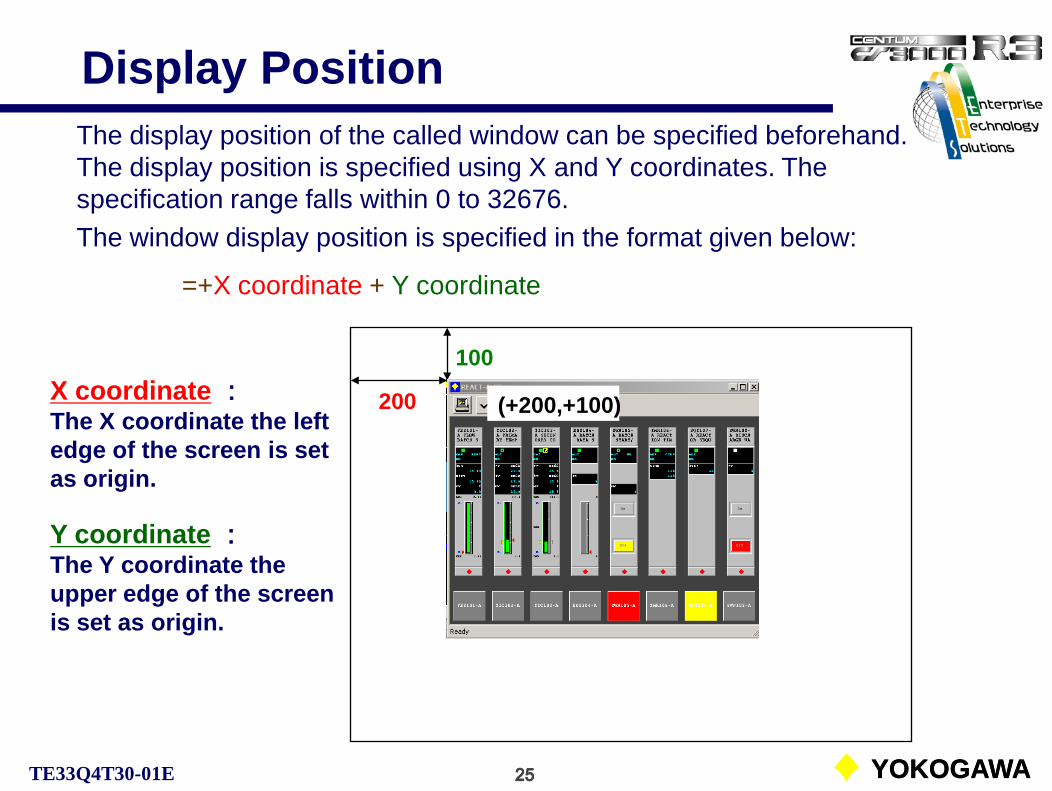
Display PositionThe display position of the called window can be specified beforehand.The display position is specified using X and Y coordinates. The specification range falls within 0 to 32676. The window display position is specified in the format given below:
=+X coordinate + Y coordinate
X coordinate :The X coordinate the left edge of the screen is set as origin.
200
100
Y coordinate :The Y coordinate the upper edge of the screen is set as origin.
(+200,+100)
26 YOKOGAWATE33Q4T30-01E 26 YOKOGAWA
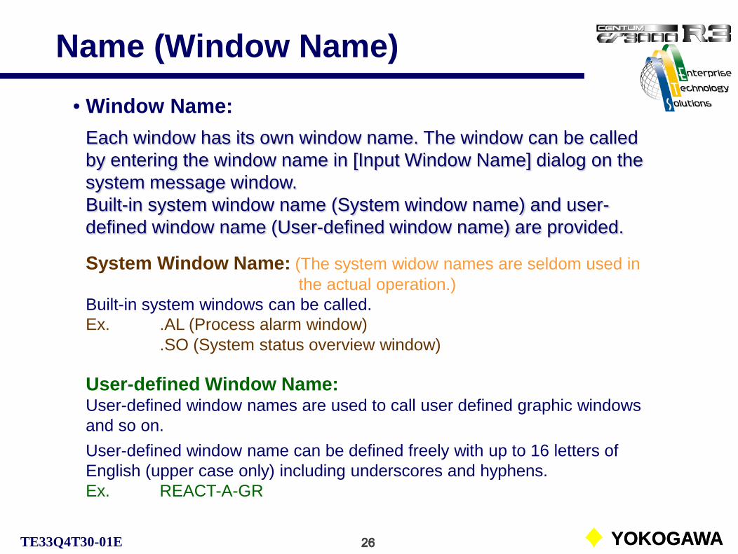
Name (Window Name)
Each window has its own window name. The window can be called by entering the window name in [Input Window Name] dialog on the system message window.Built-in system window name (System window name) and user-defined window name (User-defined window name) are provided.
System Window Name: (The system widow names are seldom used inthe actual operation.)
Built-in system windows can be called.Ex. .AL (Process alarm window)
.SO (System status overview window)
User-defined Window Name:User-defined window names are used to call user defined graphic windows and so on.User-defined window name can be defined freely with up to 16 letters of English (upper case only) including underscores and hyphens.Ex. REACT-A-GR
• Window Name:

27 YOKOGAWATE33Q4T30-01E 27 YOKOGAWA
Name (Tag Name)
The names, which are assigned to identify function blocks, elements and so on in the control stations are called tag names. There are two kinds of the tag names; system tag names and user-defined tag names.
• Tag name:
System tag name:The system tag name is the built-in default tag name and used to call elements and so on. It consists of % [element code] [element number] S [domain number] [station number].
Ex. %SW0100S0101 (common switch)
The system tag name format. %aabbbbSccddaa: Element identifier bbbb: Element No. cc: Domain No. dd: Station No.
User-defined tag name:Used to call user-defined function blocks or elements. The user-defined tag name can be defined freely with up to 16 letters (upper case only) and numerical figures including underscores and hyphens.
Ex. TIC102-A

28 YOKOGAWATE33Q4T30-01E 28 YOKOGAWA
Window HierarchyEvery operation and monitoring window can be organized systematically based on the concept “window hierarchy”.The window hierarchy enables calling a window in the lower hierarchy from one in the upper hierarchy, and alarm monitoring operation.
When a window hierarchy is used, the desired window can be called directly without having to remember the window name. Also the hierarchical relationship of the windows can be understood visually.
Hierarchy 1 (Upper)
Hierarchy 2
Hierarchy 3 (Lower)

29 YOKOGAWATE33Q4T30-01E 29 YOKOGAWA
Calling up Window
● Calling Operation and Monitoring Window DirectlyThis method calls a window directly by selecting a button of the window or by entering the window name.• Calling windows from the system message window.• Calling windows from the navigator window.• Calling windows by entering its name.• Calling windows from the operation and monitoring window toolbar.• Calling windows based on window calling definition.• Calling windows from the operation keyboard.
● Calling Windows in Association with the Function BlocksThis method calls windows by selecting objects or messages associated with the function blocks.
● Calling Windows based on the Window HierarchyThis method calls windows by using the window calling buttons provided by the system message window or operation keyboard based on a reference window.

30 YOKOGAWATE33Q4T30-01E 30 YOKOGAWA
System Message Window
The system message window provides following menu buttons:• Toolbox button • Preset menu button• Operation menu button• Window call menu button
An example of calling a window from [Window Call Menu] button on the system message window.
Clicking these buttons displays menus and a toolbox that are used to call the operation and monitoring windows.

31 YOKOGAWATE33Q4T30-01E 31 YOKOGAWA
Navigator WindowIn the navigator window, the window hierarchy is displayed together with the window icons.From the navigator window, a specific window in the hierarchy can be called up, or an upper window or a sibling window of the current window can be called up.
An example of calling a specific window from the navigator window.

32 YOKOGAWATE33Q4T30-01E
Entering Window Name (1)
Lower case characters change automatically to upper-case characters.
100
The name input dialog box is called from the system message window or the operation keyboard to enter the window name.Input Format in the Input Window Name Dialog Box:The following is the input format used when calling up windows from the Input Window Name dialog box.
Window name {nFunction type} {nDisplay size} {nDisplay position}{ }: Items in brackets can be omitted.n: A space
200

33 YOKOGAWATE33Q4T30-01E 33 YOKOGAWA
Entering Window Name (2)Recalling a Window:Up to 8 window names previously entered in the name input dialog box are saved.By clicking the window name display button, the saved window names are displayed in the pull-down menu.To call up a window, select the window name and then click on [OK] button.

34 YOKOGAWATE33Q4T30-01E 34 YOKOGAWA
Toolbar Associated windows can be called using the call button provided in the operation and monitoring window toolbar.
Example: The toolbar of the tuning window provides buttons to call associated windows with the function block (control drawing window).

35 YOKOGAWATE33Q4T30-01E 35 YOKOGAWA
Window Call Definition By assigning a window call function to a graphic or a function key beforehand using the system generation function, a window can be called by operating the graphic object or the function key.
Example: By double clicking on the touch target (object) assigned on the tag name, defined tuning window of the tag can be directly called.

36 YOKOGAWATE33Q4T30-01E 36 YOKOGAWA
Operation Keyboard
An operation and monitoring window can be called up directly by pressing the window call key.
Window call key
A graphic window can be directly called from the graphic window call key.

37 YOKOGAWATE33Q4T30-01E 37 YOKOGAWA
Function BlocksWhen a window calling button or key is operated while selecting an object or message associated with the function block, the window associated with the selected function block can be called directly.
For example, when the function block TIC102-A is being selected, from the tool box:
The process alarm individual acknowledge window associated with the selected function block is called.
The trend window containing the selected function block is called.
The help dialog associated with the selected function block is called.

38 YOKOGAWATE33Q4T30-01E 38 YOKOGAWA
Window Call by Hierarchy (1)When window call buttons or keys are operated while no object or message is selected in the window, the reference window based on the window hierarchy or the window related to the window that is active at the time of the call is called up.However, when an upper window is defined with the function block definition builder, the defined window is called up first. When the upper window is defined, the defined upper window can be called neglecting the window hierarchy for the operation and monitoring functions.
Window hierarchy
An upper window can be freely defined with the builder function.
39 YOKOGAWATE33Q4T30-01E 39 YOKOGAWA
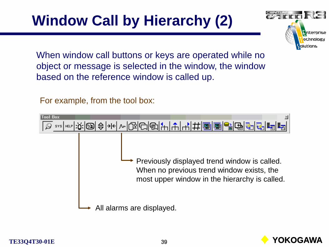
Window Call by Hierarchy (2)
All alarms are displayed.
Previously displayed trend window is called. When no previous trend window exists, the most upper window in the hierarchy is called.
For example, from the tool box:
When window call buttons or keys are operated while no object or message is selected in the window, the window based on the reference window is called up.
40 YOKOGAWATE33Q4T30-01E 40 YOKOGAWA
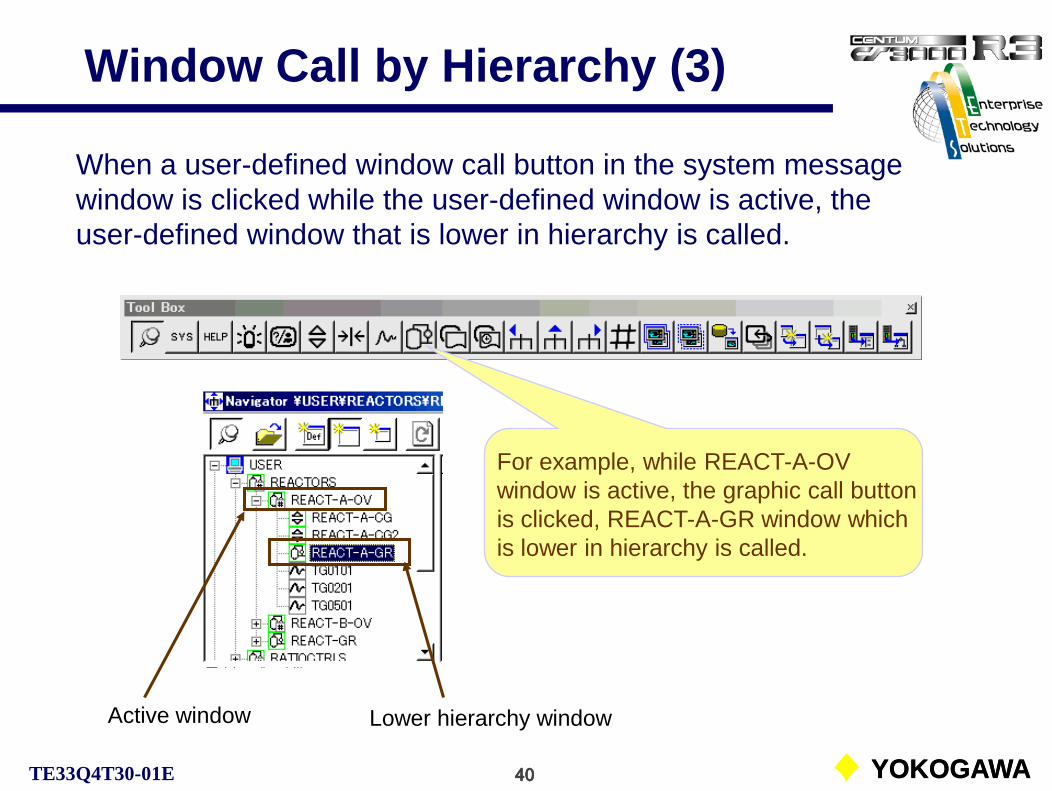
Window Call by Hierarchy (3)
For example, while REACT-A-OV window is active, the graphic call button is clicked, REACT-A-GR window which is lower in hierarchy is called.
Active window Lower hierarchy window
When a user-defined window call button in the system message window is clicked while the user-defined window is active, the user-defined window that is lower in hierarchy is called.

41 YOKOGAWATE33Q4T30-01E 41 YOKOGAWA
Upper Hierarchy Window Call
Active windowUpper hierarchy window
When the active window has an upper hierarchy window, that upper hierarchy window can be called.
For example, while REACT-A-CG2 window is active, the upper window call button is clicked, REACT-A-OV window which is upper in hierarchy is called.

42 YOKOGAWATE33Q4T30-01E 42 YOKOGAWA
Sibling Window CallWidows of the same type and belonging to the same window hierarchy are called sibling windows.When a displayed window has sibling windows, by clicking on the right or left hierarchy widow call button in the toolbox, the sibling window is called.
Windows of the same type and same hierarchy.
For example, while REACT-A-OV window is active, the right sibling window call button is clicked, REACT-B-OV window which is in the same hierarchy is called.
The left button calls the upper located and the right button calls lower located sibling window.

43 YOKOGAWATE33Q4T30-01E 43 YOKOGAWA
Display Always Window
Any number of operation and monitoring windows can be specified as the [Display always] window. It is possible to specify 6 windows as [Display always]. However, window erasing is the same for the windows not [Display always].
A total of up to 6 operation and monitoring windows can be displayed at one time. If an additional operation and monitoring window not currently displayed is called up, when already 6 operation and monitoring windows are displayed, the first displayed window is erased and newly called window is displayed.When [Display always] is in effect, the operations and monitoring window specified as [Display always] won’t be erased even new operation and monitoring window is called.
Display alwaysDefault setting

44 YOKOGAWATE33Q4T30-01E 44 YOKOGAWA
Window Closing
Close All Windows:All windows can be closed with [Clear all] button in the system message window or [Clear all] key on the operation keyboard.
The method to close each window is the same as to close the Windows general application windows.
[Clear all] button on the operation and monitoring window closes all operation and monitoring windows except the system message window. (The Windows general application windows are not included.)
Window close button
Clear all button

45 YOKOGAWATE33Q4T30-01E 45 YOKOGAWA
Circulate Windows
The window circulate function toggles between the top and bottom positions of the operation and monitoring window group and the Windows general application window group.
Circulate operation
Circulate button

46 YOKOGAWATE33Q4T30-01E 46 YOKOGAWA
Dynamic Window SetThe dynamic window set saves the currently displayed operation and monitoring windows with window names, display positions, display sizes and so on as a dynamic window set.
For example, save the active REACT-A-CG window displaying multiple windows as a dynamic window set. When the REACT-A-CG window is recalled, the saved window set is displayed.
Dynamic window set save button
Dynamic window set release button

47 YOKOGAWATE33Q4T30-01E 47 YOKOGAWA
Dynamic Window SetThe dynamic widow set common for all users and the dynamic widow set for each user exist. It is defied with the HIS setup window.
Up to 50 dynamic widow sets can be saved. If the multiple save operations are executed for the same reference window, only the last window set is saved.
Saved dynamic window set can be confirmed.

48 YOKOGAWATE33Q4T30-01E 48 YOKOGAWA
Print ScreenThe print screen function prints or stores in a file or output to a printer the entire screen or the window image (Max. 10 files). The screen image stored in the file can be displayed in the image window.
Copy button in the toolbar stores screen image.
Image file display button in the tool box calls the image window.
Window name is ‘Image’.

49 YOKOGAWATE33Q4T30-01E 49 YOKOGAWA
Rotate Windows
The window rotate function toggles between the top and bottom positions of the operation and monitoring windows.
Rotate button
Rotate operation

50 YOKOGAWATE33Q4T30-01E 50 YOKOGAWA
Panel Set (CS3000)The panel set function enables to call up multiple windows together to multiple HIS. Combination of several windows that are frequently used can be defined as a panel set and the panel set can be called up with one-touch operation. (CS3000 function)
The panel set call operation defined on a function key displays the defined panel set on the own HIS, or notifies the panel set name to other HIS that is defined by the builder. The other HIS display the notified panel set.
PSET notification to
HIS0123
PSET operation of HIS0124HIS0124 HIS0123

51 YOKOGAWATE33Q4T30-01E 51 YOKOGAWA
Operation Group and Buzzer ACK ID
•Operation GroupA number of HIS on the same communication bus system configured as the same operation group. The operation and monitoring can be performed in the unit of group. This group is called an operation group.
The operation group functions are such as the acknowledgement of operator guide messages, panel set call and the deletion of messages.
•Buzzer ACK IDA number of HIS on the same communication bus system is able to have the same buzzer ACK ID.
The buzzer ACK ID is the function to reset the buzzer of other HIS having the same buzzer ACK ID by the acknowledge operation with a single HIS.

52 YOKOGAWATE33Q4T30-01E
System Message and Navigator Windows
CS1000/3000 Engineering Course Textbook
B-2 System Message and Navigator Windows
01. System Message Window
02. Navigator Window

53 YOKOGAWATE33Q4T30-01E
System Message WindowSystem message window of CS1000/CS3000 (Window mode)
System message window

54 YOKOGAWATE33Q4T30-01E
System Message Window
Toolbar Date and time display area
Message display area Icon display area
The system message window consists of a toolbar, message display area, icon display area and date and time display area. Displays the latest alarms and messages and calls various operation and monitoring windows via button operation. This window enables basic operation and monitoring of a plant collectively.The system message window is called up automatically when HIS starts up. The window is displayed at the front of other windows except the toolbox.

55 YOKOGAWATE33Q4T30-01E
ToolbarThe toolbar is used to call the operation and monitoring windows. It also indicates the status of generated alarms by its button color and flashing state.
Process alarm window *
User-in dialog
System alarm window *
Operator guide window *
Message monitoring window
Window call menu
Operation menu
Preset window menu
Toolbox
Navigator window
Name input dialog
Circulate
Clear-all
Buzzer reset
Hard copy
¤ Pull-down menu exists.* Color and flashing state may change.
¤
¤
¤¤

56 YOKOGAWATE33Q4T30-01E
Tool BoxDisplay always
System status displayHelp
Process alarm
Tuning
TrendGraphic
Process reportUpper
Save window set
Operator guide
Control
Historical report
Image
RotateLarge size
Middle sizeBuilder call *
Drawing call *
Right (Sibling window call downward)
Overview
Release window set* Optional
Left (Sibling window call upward)

57 YOKOGAWATE33Q4T30-01E
Tool-hintWhen the mouse cursor is brought near a tool button, the tool-hint (button name) may popped up. If not, click on the toolbar to make active and try again.
Toolbox
Graphic
Toolbox
Toolbar ( system message window)
The form of the toolbox can be changed and displayed always. A window call with a single action is possible without an operation keyboard.
See Supplement II. Toolbars of Various Windows.

58 YOKOGAWATE33Q4T30-01E
Menu Display from Toolbar
Operation menu
Preset window menu
Toolbox

59 YOKOGAWATE33Q4T30-01E
Message Display Area
On the message display area of the system message window, the latest unacknowledged single message among process alarm messages, annunciator messages and system alarm messages is displayed. When unacknowledged messages exist, the corresponding buttons may flash.When the message display button or the message display area is clicked, the latest 5 unacknowledged messages are pull-down displayed.
Message display area Message display button

60 YOKOGAWATE33Q4T30-01E
Icon Display Area
In the icon display area of the system message window, icons that indicate the state of the own station or the system is displayed.
System view is operatingIcon display area
Under virtual test
I/O is disconnected (Under test condition)
Equalization is required
Isolated HIS
No icons are displayed while the operation is normal.

61 YOKOGAWATE33Q4T30-01E
Navigator WindowHIS classifies all user-defined windows used for the operation and monitoring, and displays hierarchically. With this display, the user can grasp the architecture of the windows used in the system at a glance. The window is called the navigator window.
Toolbar
Status bar
Hierarchical pane
Window pane
User-defined windows
System-defined windowsRecipe-related windows

62 YOKOGAWATE33Q4T30-01E
Toolbar in Navigator Window
Selected window call (similar to a double-clicking)
The navigator window consists of a toolbar, a window hierarchy display area and a status bar.
Move to the currently active window pane.
Display window in large size
Display window in default size.
Display window in middle size
When the window saved as a reference window of a window set is called up in default size, the window set is displayed.

63 YOKOGAWATE33Q4T30-01E
Icons in Navigator Window
On the side of the window names in the navigator widow, the icons that indicate the widow types are displayed.
Icons frequently used window types.
Graphic window (overview attribute)
Graphic window (graphic attribute)
Graphic window (control attribute)
Trend window
Process alarm window
Operator guide window
System status overview window
HIS setup window
System alarm window
FCS status display window
BCV status display window
Process report window
Product overview window
Product control window
Shortcut window (e.g. for graphic window)
Top hierarchy (User-defined window, system window, receipt related window)

64 YOKOGAWATE33Q4T30-01E
Alarm Display in Navigator WindowThe colors of the icons for windows that indicate states of alarms or messages change according to the alarm occurrence status. The users, therefore, can visually determine in which of the function block being monitored in the window is generating the alarm.
• Entire icon is redIndicates there is an unacknowledged alarm.
• Entire icon is greenIndicates that the alarm returned to normal state but not acknowledged.
• Icon’s edge is redIndicates there is an acknowledged alarm.
• Icon’s edge is greenIndicates that no alarm occurs.

65 YOKOGAWATE33Q4T30-01E
Standard Windows
CS1000/3000 Engineering Course Textbook
B-3 Standard Operation and Monitoring Windows
01. Faceplate Window02. Graphic Window03. Overview Window04. Control Window05. Tuning Window06. Trend Window07. Process Alarm Window08. Operator Guide Window09. Message Monitoring Window

66 YOKOGAWATE33Q4T30-01E
Faceplate Window
The faceplate window is used not only for monitoring but also for setting or operating directly any function blocks (controllers, indicators, transfer switches etc.) and internal elements (internal switches, timers, counters etc.) defined in the control system.
One faceplate window is provided for each function block and internal element. The instrument faceplate that is called up directly is referred to as the faceplate window.

67 YOKOGAWATE33Q4T30-01E
Faceplate Window ConfigurationThe instrument faceplate consists of the following elements:
Comment display area
Status display area
Parameter display area
Instrument display area
Operation mark
Data entry dialog box call buttonINHIBIT

68 YOKOGAWATE33Q4T30-01E
Status / Parameter Display Area
Tag mark
Block mode
Alarm status
Calibration status
Cascade mark
Alarm OFF status
The status display area and the parameter display area consist of the following elements:
According to the type of instruments or control functions block status or CMP mark may be displayed.
Engineering unit
Data item name
CAL AOF
(AOF color)

69 YOKOGAWATE33Q4T30-01E
Tag Mark TypeThe tag mark indicates the tag importance level and the status of the function block. All function blocks have the tag mark. There are following types of the tag mark according to its importance level:
Important tagGeneral tagAuxiliary tagThe functions related to the tag importance are as follows:Acknowledgement at operation.Alarm flashing.Alarm re-warning.● Important tagAlarm processing level 1Locked type flashing with re-warning functionAcknowledgement required at operation● General tagAlarm processing level 2Locked type flashing● Auxiliary tagAlarm processing level 3Non-locked type flashingSee Supplement III. Alarm Priority.

70 YOKOGAWATE33Q4T30-01E
Tag Mark ColorThe table below shows an example of the tag mark color and alarm status correspondence.
Flashing redAlarm message has been initiated but not been acknowledged.Flashing green
Alarm recovery message has been initiated but not been acknowledged.Constant red or green
Alarm message or recovery message has been initiated and acknowledged.
Color Process Status Examples of Alarm StatusBlue Alarm output off AOFRed Alarm occurrence LO, HI, IOP, LL, HH, OOP
Yellow Alarm occurrence ±DV, ±VEL, MLO, MHI
Green Normal NRWhite No alarm function provided -Gray Communication error -
See Supplement V. Alarm Status.

71 YOKOGAWATE33Q4T30-01E
Alarm ActionsHigh and medium priority alarm.
Low priority alarm.
Logging and reference alarm.

72 YOKOGAWATE33Q4T30-01E
Re-warning Alarm• Timer repeated warning:
The timer repeated warning function outputs the message ateach repeated warning cycle.
Operation by re-warning
Operation by re-warning
Acknowledgement

73 YOKOGAWATE33Q4T30-01E
Flashing state of Tag Mark
Occurrence
Recovery Occurrence
Acknowledgement
Recovery
Re-warning(High-priority alarm)
Tag mark color and flashing states transition.
Alarm absent state
Flashing OFF
Alarm absent state
Flashing ON
Alarm present
stateFlashing
OFF
Alarm present
stateFlashing
ON
Acknowledgement
Recovery(Non-lock type)

74 YOKOGAWATE33Q4T30-01E
Display Area of InstrumentThe display area of the instrument provides the bars that represent the manipulated output variable (MV) high and low limit, and the setpoint variable (SV) high, high-high, low, and low-low limit.
The operation exceeding limit values needs confirm operation.
Operation setpoint high-high limit (HH)
MV high limit (MH)
MV operation limit bar
MV operation key
MV low limit (ML)
Operation setpoint high limit (PH)
Operation setpoint operation limit bar
SV operation key
Operation setpoint low limit (PL)
Operation setpoint low-low limit (LL)PV bar
MV index (OPHI)
MV index (OPLO)
Open/Close mark

75 YOKOGAWATE33Q4T30-01E
Operation of Instrument FaceplateThe following operations are possible with the instrument faceplate:• Block mode transfer• INC/DEC of data• Data input
Block mode transfer operation:A single click on the block mode calls a bock mode transfer dialog.
MAN(Manual)
AUT(Auto)
CAS(Cascade)
Mode change is also possible with the mode change keys on the operation keyboard.
INHIBIT

76 YOKOGAWATE33Q4T30-01E
Operation of Instrument Faceplate
Item selection button
Data INC/DEC operation:When an operable pointer* is clicked, the INC/DEC operation dialog corresponding to the pointer appears.
INC/DEC operation button
Data input area
Data input operation:
When the data input dialog of the instrument faceplate is clicked, the data input dialog appears.The data item that corresponds to the red pointer appears. The data item can be selected by the item selection button.
* [MAN]: MV & SV, [AUT]: SV, [CAS]: -When the MV or SV is being manipulated, the pointer turnsto red. When it is not manipulated, it turns to yellow.

77 YOKOGAWATE33Q4T30-01E
Graphic WindowThe graphic window with graphic attribute is the pane that users can freely create using various objects in order to recognize visually the state of the process control.
State monitoring:The state of pipe lines, valves, reactors and so on is displayed with different colors. It makes grasping the overall condition easier.
Setting operation:Necessary instruments can be called by intuition. It makes the operation simple and certain.
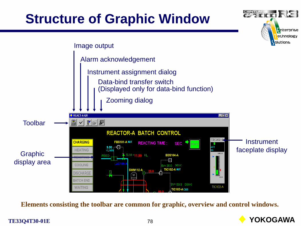
78 YOKOGAWATE33Q4T30-01E
Structure of Graphic Window
Toolbar
Elements consisting the toolbar are common for graphic, overview and control windows.
Graphic display area
Image output
Alarm acknowledgement
Instrument assignment dialogData-bind transfer switch(Displayed only for data-bind function)
Zooming dialog
Instrument faceplate display

79 YOKOGAWATE33Q4T30-01E
Data Bind Function
TIC201
PID
FIC101
PID
Raw material
Steam
FIC201
PID
System ARaw material FIC FIC101
Heating FIC FIC201
Heating TIC TIC201
Level LIC201
System A Charging
PV=XXXXL/M
PV=XXXX
PV=XXXXL/M
When the system A is selected, tag names and data of the system A substitute to display.
System BRaw material FIC FIC102
Heating FIC FIC202
Heating TIC TIC202
Level LIC202
When the system B is selected, tag names and data of the system B substitute to display.
Tank level

80 YOKOGAWATE33Q4T30-01E
Instrument Faceplate AssignmentThe instrument faceplate assignment can be changed temporary with the instrument assignment dialog. However, the Instrument faceplate size may not be changed.The defined instrument faceplate assignment is peculiar to the HIS that changed the assignment. If the graphic window definition is downloaded by the builder, this temporary defined assignment is no more effective.
Instrument faceplate assignment button
Displayed instrument faceplate

81 YOKOGAWATE33Q4T30-01E
Overview WindowThe overview window (a graphic window with overview attribute) is the window that collectively displays alarm status and so on for monitoring the process with assigned overview objects. This window that has the function to call up related windows can be used as a menu window by posting it to the top hierarchy of monitoring windows of overall plant.
Overview object:Tag name, window name, annunciator message or comment can be assigned on the overview object. Window switching function by touch target assignment and color modify function for alarm are also provided.

82 YOKOGAWATE33Q4T30-01E
Control Window (8-Loop)The control window (a graphic window with control attribute) displays the group of instruments in normal size used for the monitoring and operation. The maximum number of instruments displayed is 8. The normal size instrument can be used not only for monitoring but for operation.
Normal size instrument:The displayed instrument can be operated directly.By double-clicking the tag mark, the instrument faceplate is called.
Soft-key assignment:The soft-keys can be assigned for each instrument. Functions such as tuning window call may be assigned.

83 YOKOGAWATE33Q4T30-01E
Control Window (16-Loop)This window displays the group of compact instruments used for the monitoring. The maximum number of instruments displayed is 16. The compact size instrument cannot be operated. Only for the monitoring. It is possible to assign both the normal size and the compact size on the 16-loop window.
Compact size instruments:By double-clicking the tag mark, the instrument faceplate appears for operation.
(e.g. 5 normal size and 6 compact size instruments.)

84 YOKOGAWATE33Q4T30-01E
Tuning WindowThe tuning window displays the control status of the function block. It is also used for tuning the various control parameters, as well as for attaching and removing operation marks. The tuning window is automatically created when a function block is created with the builder.
Tuning parameter
display area
Tuning trend
Status bar
Toolbar Instrument faceplate

85 YOKOGAWATE33Q4T30-01E
Tuning Window ToolbarThe toolbar of the tuning window has buttons for tuning trend operation, operation mark installation/removal, mode transfer, related panel call and so on.
Operation mark
Tuning trend operation
Control drawing callRaw data display
Calibration modeAlarm off modeImage output
Alarm acknowledgement
Trend acquisition reserveStop/resume trend
Enlarge data axisReduce data axis
Reduce time axisEnlarge time axis
Primary direct modeDisplayed only when
PRD mode is effective.

86 YOKOGAWATE33Q4T30-01E
Tuning TrendThe tuning trend acquires process data from the function block displayed in the tuning window and displays them as a graph.
The acquisition of tuning trend begins when the tuning window is called up and stops when the tuning window is closed. The reserve function can be used to continue the tuning trend data acquisition after the tuning window is closed. The maximum number of data can be reserved is 16 per HIS. If more than 16 data are reserved, the oldest data are deleted.
Display time spanData axis reducing /
enlarging rate
The process data items acquired from the function block and the corresponding display colors are:• Process variable (PV), calculated output value (CPV), feedback input data (FV) [Cyan]• Setpoint value (SV), switch position (SW) • Manipulated output value (MV) [Magenta]
[White]
The sampling period is 1 second and the recording span is 48 minutes.
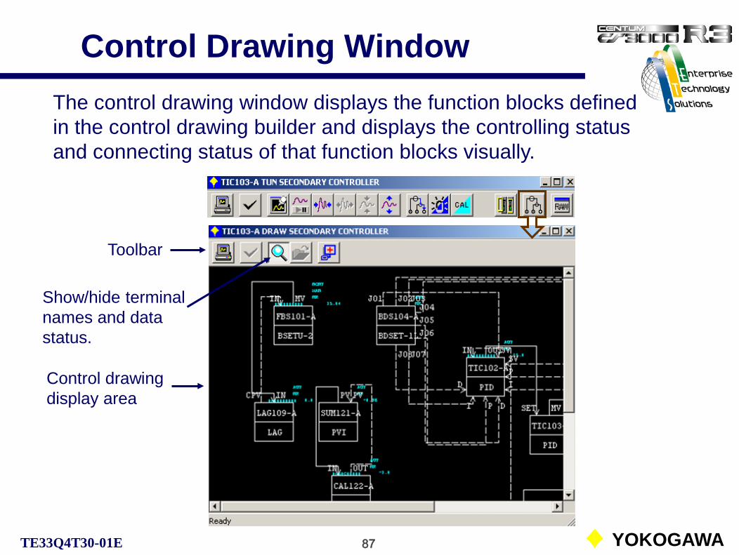
87 YOKOGAWATE33Q4T30-01E
Control Drawing WindowThe control drawing window displays the function blocks defined in the control drawing builder and displays the controlling status and connecting status of that function blocks visually.
Toolbar
Control drawing display area
Show/hide terminal names and data status.

88 YOKOGAWATE33Q4T30-01E
Control Drawing Window
The sequence table window can be used to monitor the scan status of the sequence table and the status of conditions.
Toolbar
Table display area
Status bar color:Yellow: Non-executing ruleGreen: Condition not satisfiedRed: Condition satisfied
Condition pattern color:Cyan: Condition not satisfiedRed: Condition satisfied

89 YOKOGAWATE33Q4T30-01E
Trend WindowThe trend window acquires different types of process data and displays time-series change in a graph. The maximum number of trend points can be displayed is 8.
Numerical data display area
Toolbar
Trend data display area
Status bar

90 YOKOGAWATE33Q4T30-01E
Structure of Trend
Trend groupTG0101
1 FIC100.PV2 TIC200.PV3 LIC300.PV45678
LIC300.PV3 LIC300.PV
The trend recording consists of the three layers of the trend blocks, the trend windows and the trend point windows.Trend blockTrend block 01
TR0001Trend block 02
TR0002Trend block 03
TR0003
Trend block 50TR0050
Trend group 1TG0101
Trend group 2TG0102
Trend group 3TG0103
Trend group 16TG0116
Trend window
Trend point window
Trend window nameTGbbggbb: Block numbergg: Group number
Maximum number trend blocks for CS1000 is 8.
Each trend block can specifies trend type and sampling period.

91 YOKOGAWATE33Q4T30-01E
Trend Data Acquisition Types
The data acquisition includes the following four types:
Continuous-rotary type:Process data are acquired constantly. Data acquisition starts automatically after starting the operation and monitoring functions. When the storage capacity becomes full, the oldest data are deleted and replaced by new data.
Batch-stop type:Data acquisition starts and stops according to the received command. When the storage capacity becomes full, data acquisition stops.
Batch-rotary type:Data acquisition starts and stops according to the received command. If no stop command is given and the storage capacity becomes full, the oldest data are deleted and replaced by new data.
Trend acquired by other HIS:Trend data acquired by other HIS may be referenced in a unit of block.

92 YOKOGAWATE33Q4T30-01E
Sampling Period and Recording Span
In order to preserve the trend data, save the each trend window as a file or utilize the long-term data archive function (optional).
The sampling period can be selected from 1 second, 10 seconds, 1 minute, 2 minutes, 5 minutes and 10 minutes for each trend block. No more than 18 blocks (8 blocks for CS1000) can be specified with the sampling periods of 1 minute, 2 minutes, 5 minutes and 10 minutes. No more than 2 trend blocks can be specified with the sampling period of 1 second or 10 seconds.
2,880 samples can be acquired per pen. The recording span indicates the time to acquire 2,880 samples for each trend in the specified sampling period.
The table below shows the relationship between the sampling period and the recording span:

93 YOKOGAWATE33Q4T30-01E
Toolbar of Trend Window
The trend window toolbar can be used to perform tasks such as reducing or enlarging the trend graph, batch trend operation, trend data save and redisplay.
Image output
Not effective
Long-term trend data save file:Displayed only when the long term data save function is effective.
Pen assignment dialog
Trend display update suspension
Time axis enlarging
Time axis reducing Data axis reducingData axis enlarging
Pen number displayReference pattern display
Display initializing
Trend data save
Saved trend call
Batch trend pauseBatch trend start
Trend recall

94 YOKOGAWATE33Q4T30-01E
Trend Graph Display AreaIn the trend graph display area of the trend window, the trend data acquired according to the trend pen assignment are displayed.
Index mark(Cyan)
Time display‘*’ mark may be added to the displayed time for time change or power failure.
Index mark right move button
Index mark left move button
Time at index mark

95 YOKOGAWATE33Q4T30-01E
Data Display Area and Status BarThe instantaneous value of the trend data and function block information for each trend pen corresponding to the time specified by the trend graph index mark are displayed in the numeric trend data display area of the trend window.
The trend gathering status, display span of the trend graph time and reducing/enlarging scale for the data axis on the trend graph is displayed on the status bar of the tend window.
Numeric trend data display
area
Data item nameInstantaneous value
Status bar
Trend gathering status display
Display span of trend graph time axis
Data axis reducing/enlarging scale

96 YOKOGAWATE33Q4T30-01E
Trend Point WindowThe trend point window displays one of the 8 points of the trend data assigned to trend window. It can be called up from the trend window by selecting a trend pen.
Toolbar
Data display area
Status bar

97 YOKOGAWATE33Q4T30-01E
Changing Displayed Trend Data
In the trend window, the assigned trend pen may be changed.
Changing pen assignment displaying trend data:
The builder defined pen assignment can be changed temporary by calling up the pen assignment dialog with the pen assignment button on the toolbar.
To display the builder defined pen assignment, use display initialize button.

98 YOKOGAWATE33Q4T30-01E
Trend Data SaveThe acquired trend data can be saved in another file. Saving operation in the file is executed for the trend group unit.
To save the displayed trend data, call up the Save AS dialog by clicking the data save button on the toolbar. Enter the file name and the position to save. The file extension “trf” is automatically added.
The saved trend data will be redisplayed on the trend window where the [Saved trend call] button was clicked. The originally displayed trend graph will be replaced. The original trend can be recalled with the [Trend recall] button.
The saved trend can be redisplayed by clicking the display button to select the trend file.

99 YOKOGAWATE33Q4T30-01E
Reference Pattern Assignment
For the batch type trend, specified trend data can be assigned as a reference pattern.
The trend reference pattern, an ideal trend pattern such as the trend record by an operator with expertise can be displayed in the trend window.
When the trend point window is displayed, the related reference pattern is also displayed.
Reference Patterns

100 YOKOGAWATE33Q4T30-01E
Process Alarm WindowThe process alarm window displays process alarms in the order they are generated starting with the most recent alarm. When the alarm is generated, the buzzer sounds and the process alarm button on the system message window and the LED of the process alarm key on the operation keyboard start flashing to notify the operator.
Toolbar
Message display area
Status bar
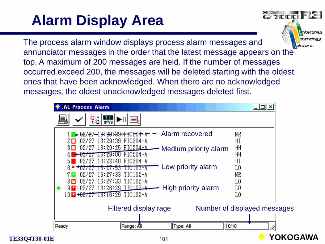
101 YOKOGAWATE33Q4T30-01E
Alarm Display AreaThe process alarm window displays process alarm messages and annunciator messages in the order that the latest message appears on the top. A maximum of 200 messages are held. If the number of messages occurred exceed 200, the messages will be deleted starting with the oldest ones that have been acknowledged. When there are no acknowledged messages, the oldest unacknowledged messages deleted first.
Medium priority alarm
Alarm recovered
Low priority alarm
High priority alarm
Filtered display rage Number of displayed messages

102 YOKOGAWATE33Q4T30-01E
Tag Mark Color and StatusThe tag mark flashes until the message is acknowledged.
Red !: LO alarm re-warningRed: LO alarm generation
Green: Normal recoveryRed edge: HI alarm recoveryRed frame: HH alarm recoveryRed: HH alarm generationRed: HI alarm generation
Green: Normal recoveryRed: LO alarm recovery
Red: LO alarm generation

103 YOKOGAWATE33Q4T30-01E
Process Alarm Message Search
The filter dialog can be used to display only specific process alarm messages.
Current process variable display
Filter dialog
High priority alarm display
Alarm display updating pause/restart

104 YOKOGAWATE33Q4T30-01E
Process Alarm Notification FlowSystem message window
Process alarm
occurrence
Graphic window
Process alarm window
Related window
Alarm acknowledgement
PrintoutBuzzer soundsSave in file
Navigator window

105 YOKOGAWATE33Q4T30-01E
Toolbar
Message display area
Operator Guide WindowThe operator guide window displays in order the operator guide messages occurred. When a message is initiated, buzzer is activated and the button on the system message window and the LED of the operator guide message key on the operation keyboard starts flashing to notify the operator.
Status bar

106 YOKOGAWATE33Q4T30-01E
O. G. Message Display AreaA maximum of 40 messages are held. If the number of messages occurred exceeds 40, the messages will be deleted starting with the oldest ones that have been acknowledged.
Interactive message button(For CS batch function only)
Operator guide message mark(The mark for the interactive is .)
Filtered display rage Number of displayed messages

107 YOKOGAWATE33Q4T30-01E
O. G. Message Search
The filter button on the toolbar is used to call up the filter dialog.
The filter dialog can be used to display only specific operator guide messages.
Equipment search

108 YOKOGAWATE33Q4T30-01E
Message Monitor Window
The message monitor window acquires only specified messages from many messages and displays to confirm them in real-time.
Toolbar
Message display area
Status bar

109 YOKOGAWATE33Q4T30-01E
Message Monitor WindowThe messages to be displayed in the message monitor window are specified with the message registration dialog. The dialog specifies the message type, color and the number of messages.
Maximum number of messagesUp to 200
Display message selection
Display color selection

110 YOKOGAWATE33Q4T30-01E
Message Search
The filter dialog can be used to display only specific operation record messages.
The filter button on the toolbar is used to call up the filter dialog.

111 YOKOGAWATE33Q4T30-01E
Help Dialog BoxThe help dialog box displays the pre-defined help messages. It can be used as the on-line manual during operation.The help dialog box may be called up from an active operation and monitoring window, from a selected function block in the window or from a selected system alarm message by clicking the help button to display a related help message.

1 YOKOGAWATE33Q4T30-01E
Control Station (FCS)
CS1000/3000 Fundamental Course TextbookPART- C Control Station
Standard Type FCS
C-1 Types of control StationsC-2 Node configurationC-3 I/O DevicesC-4 Reliability of FCSC-5 Configuration of FCS FunctionsC-6 I/O Functions of FCS

2 YOKOGAWATE33Q4T30-01E
Types of Control Stations CS3000 R3.04 has 8 types of FCS.
For V, XL migration
SFCSCompact
FCS
(RIO)
RIO FIO
LFCSStandard
FCS
(RIO)
LFCS2Enhanced
FCS(32M)(RIO)
FFCSCompact
FCS
(FIO)
KFCSStandard
FCS
(FIO)
KFCS2Enhanced
FCS(32M)(FIO)
RFCS2Migration
FCS(16M)
(FIO,SIO)
RFCS5Migration
FCS(32M)
(FIO,SIO)
Common hardwareCommon hardware
PFCSCompact
FCS
(RIO)
FFCS-SCompact
FCS
(FIO)
For CS1000 For small CS3000
Different memory capacity
Different memory capacity

3 YOKOGAWATE33Q4T30-01E
Structure of Various FCS
ooo
Compact FCS for FIO(FFCS/FFCS-S)
Compact FCS for RIO(SFCS)
Standard FCS for RIO(LFCS)Standard FCS for FIO
(KFCS)
The field control station that directly connects a control unit and I/O units. (FFCS: with node, FFCS-S: without node)
The field control station that connects a control unit and nodes with the ESB bus.(Maximum 10 nodes)
The field control station that directly connects a control unit and I/O module nests. (No node is used.)Equivalent to PFCS of CS1000.
The field control station that connects a control unit and nodes with the RIO bus.(Maximum 8 nodes)

4 YOKOGAWATE33Q4T30-01E
ER bus
ESB bus
FCU(Field Control Unit)
Standard Type FCS ConfigurationStandard FCS for FIO
KFCSStandard FCS for RIO
LFCSFCU
(Field Control Unit)
Node
Node Interface
Unit
I/O Units
I/O Modules
SUB-system
Node
SUB-system
RIO bus

5 YOKOGAWATE33Q4T30-01E
Control Station (KFCS)
Dual redundant control unit (FCU) in the standard cabinet.

6 YOKOGAWATE33Q4T30-01E
Dual Redundant Control Unit
Dual redundant control unit (FCU) for KFCS.

7 YOKOGAWATE33Q4T30-01E
Compact Type FCS (FFCS)
FCU
CPU modules
Power unit
modules
Dual redundant control unit of FFCS (FCU)
I/O modulesESB bus interface modules

8 YOKOGAWATE33Q4T30-01E
Compact Type FCS (PFCS/SFCS)
CPU modules
Power supply modules
I/O Units
An example of rack mounted PFCS/SFCS:
It consists of a FCU and I/O units. Control bus couplers
FCU

9 YOKOGAWATE33Q4T30-01E
Role of Node (LFCS)
Long distance use.
Shortened wiring
Field
Bus repeater
Optical bus repeater
RIO bus
Node for rack mount type
Control room
Node for rack mount type
Node for cabinet mount type
Node for rack mount type
Node for rack mount type
Nodes can reduce the wiring lengths by planning the optimum system configuration.
RIO bus connects FCU and nodes.
Transmission distance of the optical bus repeaters is either max. 4 km or 15 km.

10 YOKOGAWATE33Q4T30-01E
Node Installation (FIO)
An example of the node for FIO:I/O modules are directly mounted to a backboard.
I/O modules
ESB bus interface modulesPower supply modules
Cable tray Remote node unit uses ER bus interface unit.Node

11 YOKOGAWATE33Q4T30-01E
Node Installation (RIO)
An example of node: I/O modules are installed to the I/O module nests.
I/O moduleI/O module nest
I/O modules
IOU
IOU
Node
Analog I/O module nest
(AMN11, AMN!2)
Relay I/O module
Analog I/O module
Relay I/O module nest
(AMN21)
I/O module nest

12 YOKOGAWATE33Q4T30-01E
I/O Modules
RIO: Individually isolated high-performance I/O modules and multiplexer modules that utilize M4 screw terminals used by CENTUM CS for a long time.
FIO: Newly developed multiplexer type I/O modules that are connectable to the already installed CENTUM-V and XL for replacement. They are compact and abundant in types.
CS3000 R3 has two different I/O modules:
See Supplement IV. Input and Output Modules.

13 YOKOGAWATE33Q4T30-01E
I/O Units and I/O Modules (LFCS)
X8
X4 (front)X5 (rear)
Node
Analog I/O module
Analog I/O module nest
An example of the analog I/O modules and the nest.

14 YOKOGAWATE33Q4T30-01E
I/O Terminal Addressing (RIO)
Nodes
I/O Units
01 02 03
1
2
3
Slot 1
Terminal 05
TI-1001
Addressing of terminals for process connection:
%ZnnusccTerminal number (01 to 32)Slot number (1 to 4)Unit number (1 to 5)Node number (01 to 08)
An example of addressing

15 YOKOGAWATE33Q4T30-01E
I/O Modules (KFCS)
Modules for KFCS
KS cable
ML connector
I/O moduleKS cable interface adapter
From field
Variations of signal cable connection
• Terminal board used for single or dual TC/mV input (AET4D)
• Terminal board used for single or dual digital I/O (AED5D)
Pressure clamp terminal connector

16 YOKOGAWATE33Q4T30-01E
I/O Terminal Addressing (FIO)
PIO block
Format of process I/O terminal number (FIO FCS):
%ZnnusccTerminal (01 to 64)1 fixed (Segment Nos. 1 to 4: Communication modules.)Slot (1 to 8)Node number (01 to 10)
An example of terminal number

17 YOKOGAWATE33Q4T30-01E
Dual Redundant FCU
Temporary computation error which may not be prevented by the diagnostic program can be detected remarkably by collating the computation results from two CPUs.
The CENTUM CS control station adopts “a pair and spare” configuration with spare FCU modules and pair CPUs in a module, which has never been introduced in the world. By collating the computation results, once a transient error is detected, immediately control right is switched to the standby side module. Since the standby module performs control computation synchronized with the control side, control is switched without loss of continuity.
Pair configuration with two CPUs.
Spare configuration with two FCU modules.

18 YOKOGAWATE33Q4T30-01E
Perfect Dual-Redundant Loop
RIOBus card
RIOBus card
FCUFCU
RIOBus
RIOBus
RIOSlave card
RIOSlave card
NIUPSU
NIUPSU
NodeInternal bus
NodeInternal bus
AAM11
RIOBus card
RIOBus card
RIOBus
RIOBus
RIOSlave card
RIOSlave card
NIUPSU
NIUPSU
NodeInternal bus
NodeInternal bus
AAM51
AAM11 Dual-redundant input modules
(Optional)
AAM51
Dual-redundant output modules
(Optional)
The dual-redundant input modules need a dual-redundant signal selector block (SS-DUAL).

19 YOKOGAWATE33Q4T30-01E
Flow of FCS Start
RestartInitialized start
Start processing from the beginning of periodic processing.
Continue processing from the discontinued point.
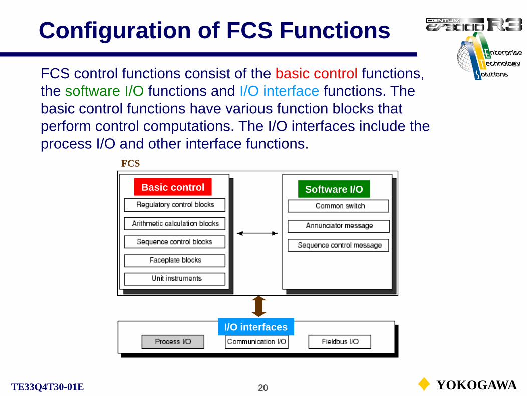
20 YOKOGAWATE33Q4T30-01E
Configuration of FCS FunctionsFCS control functions consist of the basic control functions, the software I/O functions and I/O interface functions. The basic control functions have various function blocks that perform control computations. The I/O interfaces include the process I/O and other interface functions.
FCS
Basic control Software I/O
I/O interfaces
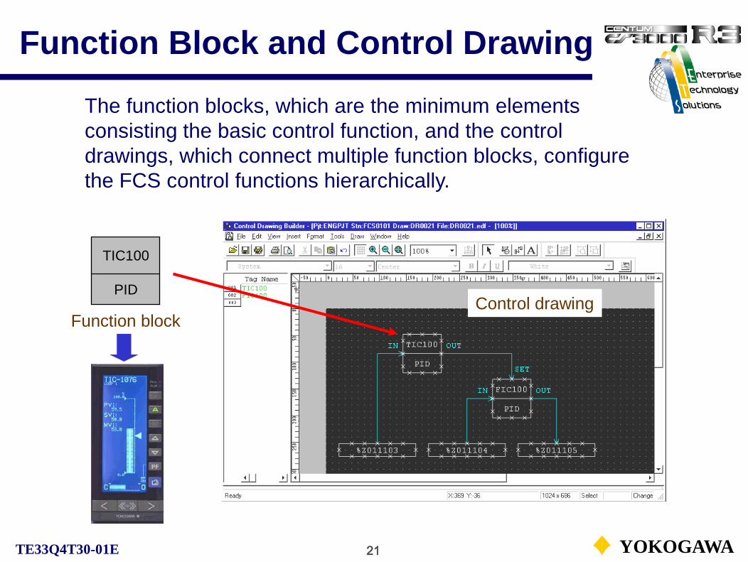
21 YOKOGAWATE33Q4T30-01E
Function Block and Control Drawing
The function blocks, which are the minimum elements consisting the basic control function, and the control drawings, which connect multiple function blocks, configure the FCS control functions hierarchically.
Function block
TIC100
PIDControl drawing

22 YOKOGAWATE33Q4T30-01E
Function BlockFunction block:The function block is the minimum element that executes control computations.Regulatory control blocks, sequential control blocks, computation blocks, SFC blocks are the function blocks. The control functions can be described like an instrumentation flow sheet by connecting regulatory control, sequential control and computation blocks.Every function block should have a tag name and be stated on a control drawing.
Function blocks(Regulatory control, Computation, Sequential control)
FIC100
PID
ST22-A
ST16
TIM201
TM
CU201
CALCU
TI100
PVI
See Supplement V. Function Block List.

23 YOKOGAWATE33Q4T30-01E
I/O Functions of FCS
FCS
The software I/O is the virtual I/O realized by the FCS software. Data setting or data reference to or from other function blocks or applications is possible.
The I/O interfaces can handle not only process I/Os but also sub-system I/Os as PLCs and fieldbus I/Os.
Basic control Software I/O
I/O interfaces

24 YOKOGAWATE33Q4T30-01E
Process I/O
The process I/Os are shown below:
Analog input:Current input, voltage input, mV input, TC input, RTD input, potentiometer input, pulse train input.
Analog output:Current output, voltage output.
Contact input:Contact ON/OFF input signals from field devices to the FCS. Two types of signals exist; status signals and push button signals.
Contact output:Contact ON/OFF output signals from the FCS to field devices.(The status output signals of a status type I/O module can be manipulated in the following styles:Latched type, non-latched type, pulse type and flashing type output.)

25 YOKOGAWATE33Q4T30-01E
Software I/O
Types of software I/O:
• Internal switch:The internal switches exchange logical values between function blocks or applications.
• Message output:The message, which transmits the occurrence of events.
The software I/O enables data setting or data reference to or from other function blocks or applications same as in the process I/O.

26 YOKOGAWATE33Q4T30-01E
Examples of Using Software I/O
Heating start
TIC101
PID
FIC101
PID
Sequence operations like SV setting, block mode switching in a regulatory control.
An internal switch latched output for the graphic display modify.
Operator guide message output
Internal Switch (Start switch) Message Output
Reactor A charge end
Heating
14:05 Reactor A heating start
Annunciator message output

27 YOKOGAWATE33Q4T30-01E
Message Output Functions
The message output functions for sequential controls are used to alert operators or to notify events to other applications.
Printout Logging Other functions
Printout message output (%PR) Yes Yes Printout with messages
Operator guide message output (%OG) Yes Yes Electronic sounds, display
Multi-media function start message output (%VM) No Yes Multi-media function start
Sequence message request (%RQ) No Yes Startup HIS functions
Supervisory computer message output (%M3) No No Event message output
Signal event message output (%EV) No No Output to SEBOL
SFC/SEBOL return-event message output (%RE) No No Output to SFC block

1 YOKOGAWATE33Q4T30-01E
Regulatory Control Functions
CS1000/3000 Fundamental Course Textbook
PART- D Regulatory Control Functions
D-1 Regulatory Control BlocksD-2 Control DrawingD-3 ProcessingD-4 Block ModesD-5 Scan and Control Periods

2 YOKOGAWATE33Q4T30-01E
Regulatory Control PositioningThe regulatory control block performs control computation processing using analog process variables and so on for the process monitoring and control.
FCS
Basic control Software I/O
I/O interfaces

3 YOKOGAWATE33Q4T30-01E
Types of Regulatory Control Block
The regulatory control blocks vary by the types of data handled and control computation processing functions provided.
• Input indicator blocks• Controller blocks• Manual loader blocks• Signal setter blocks• Signal limiter blocks• Signal selector blocks• Signal distributor blocks• Pulse count block• Alarm block• YS blocks
Types of controllers are shown below.
See Supplement V. Function Block List.

4 YOKOGAWATE33Q4T30-01E
Regulatory Control Block StructureThe structure of regulatory control function block PID:
OUT
SUB
AUTMAN
SET
CAS
IN
INTTSITINRL2RL1BIN
RCAS
(VN) (RLV1) (RLV2) (TSW)
(PV, ΔPV, MV, ΔMV)
RAW
CSV
RSV
PV
SV
RMV
MV
Detects an abnormalityin PV, MV and notifiesthe operation and monitoring functions.
Reads MV and outputs the result of output processing to the output terminal.
Reading a raw data from the input terminal, performs input processing to output PV.
Input processing
Control computation processing
Alarm processing
Output processing
CASAUT
MAN
ROUT
Reading PV and SV, performs control computation processing to output MV.

5 YOKOGAWATE33Q4T30-01E
Function Block Creation and WiringFunction block assignment and wiring on a control drawing:
Select the function block to be assigned with a selection icon.
Create a connection between function blocks, a function block and an I/O module with a wiring Icon.
Line color by automatic wiring is magenta.
Line color by manual wiring is cyan.

6 YOKOGAWATE33Q4T30-01E
Data Connection with Process I/O
There are two types of data connections with the process I/O: The data reference from a process input module and the data setting to a process output module.

7 YOKOGAWATE33Q4T30-01E
Data Connection with Function Blocks
Data connection with other function blocks is an I/O connection that connects data items such as process variables (PV) and manipulated output values (MV) held in the other function blocks, to the function block’s I/O terminals.
An example of data connection with other function blocks’ data items is shown below:

8 YOKOGAWATE33Q4T30-01E
Terminal Connection
In the cascade control, the terminal (OUT) of the function block in the upstream should be connected to the set terminal (SET) of the function block in the downstream.This connection is referred to as the terminal connection. The terminal connection is used in particular cases.
Signal flows bi-directionally.

9 YOKOGAWATE33Q4T30-01E
Input ProcessingThe processing that performs before control computation for the input signal read from the connection destination is called “Input processing”.
Input module
Analog input square root extraction
No conversion
Pulse train input
conversion
Communication input
conversion
Digital filter
Integration SUM
PVBAD
PV/FV overshoot
Input signal conversion
Read the input signal from the process Input
module or other function blocks.
Apply the 1st order lag filter to the signal from the input signal conversion function to get PV.
The function to integrate the signal from the input
signal conversion function.
CAL
CAL
CALBAD
RAW

10 YOKOGAWATE33Q4T30-01E
Input Processing (Reference)
The input processing common to regulatory control blocks and calculation blocks are as follows:
• Input signal conversion (No conversion, square root extraction, pulse train conversion, communication input conversion.)
• Digital filter
• Integration
• OV/FV/CPV overshoot
• CalibrationThe input processing of the function block can be defined with [Basic] and [Input] tabs of the function block detail definition builder.

11 YOKOGAWATE33Q4T30-01E
Calibration
The calibration is the function in which the emulated signal for a process variable (PV) or a calculated output value (CPV) in the function block can be set manually by the operation and monitoring functions for maintenance or testing.
• The color of PV bar display changes to cyan.• The process variable (PV) can be set manually.• Integration continues with the process variable (PV).• The alarm check for the process variable (PV) is bypassed.• Block mode changes to manual (MAN).
Calibration setting button

12 YOKOGAWATE33Q4T30-01E
Control Computation Processing
PID Control Computation
PID / PI-D / I-PD
PI / IVelocity / Positional
Algorithms Output actions
PV
SVMVΔMV
The PID control computation in the PID control function block calculates a manipulated output change (ΔMV) with the specified PID control algorithm (PID, PI-D, I-PD, PI or I). And then either velocity form or positional form output action converts the ΔMV to MV.The figure below shows a block diagram of PID control computation:

13 YOKOGAWATE33Q4T30-01E
Output ProcessingOutput processing refers to the processing that is executed to the values obtained from the control computation before output it.
Output limiter ΔMV limiter
Control computation MV
TRK
Output module
MAN/TRK
RMV
MH ML
Preset MV
MVrb Output conversion
MAN
TRKROUT
Aux. output No conversion
TIN SUB OUT
AUT/CAS/RCAS/PRD AUT/CAS/RCAS/ROUT/PRD
-

14 YOKOGAWATE33Q4T30-01E
Output Processing
The output processing common to the regulatory control blocks:
• Output limiter• Output velocity limiter• Output clamp• Preset manipulated output• Output tracking• Output range tracking• Manipulated output index• Output conversion (no conversion, pulse width output conversion, communication output conversion)
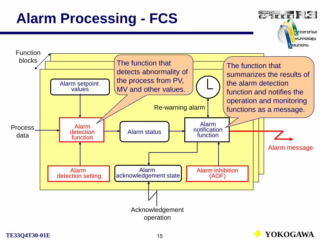
15 YOKOGAWATE33Q4T30-01E
Alarm Processing - FCS
Alarm detection function
Alarm detection setting
Alarm inhibition(AOF)
Alarm setpoint values
Alarm acknowledgement state
Alarm status
Alarm message
Process data
Function blocks
Re-warning alarm
Acknowledgement operation
The function that detects abnormality of the process from PV, MV and other values.
The function that summarizes the results of the alarm detection function and notifies the operation and monitoring functions as a message.
Alarm notification
function

16 YOKOGAWATE33Q4T30-01E
Alarm Detection Function
The following alarm detections are performed:
• Input open alarm check• Input error alarm check• Input high-high/low-low limit alarm check• Input high/low limit alarm check• Input velocity alarm check• Deviation alarm check• Output open alarm check• Output high/low-limit alarm check• Connection failure alarm check
Data item
HH, LLPH, PLVLDV
MH, ML
Alarm statusIOP, IOP-IOP, IOP-HH, LLHI, LOVEL+, VEL-DV+, DV-OOPMHI, MLOCNF
Colors of alarm status are of default.
See Supplement VI. Alarm Status.

17 YOKOGAWATE33Q4T30-01E
Alarm Inhibition (Alarm OFF)
The alarm inhibition can be used to temporarily inhibit the action of process alarm messages while the alarm detection is still active.
AOF setting button

18 YOKOGAWATE33Q4T30-01E
Block Mode and Status
Block mode and status are the information that represent the conditions of the function blocks.
Represent the operating state of the function blocks.
Represents the alarm state of the process.Represents the quality of the process data.
Block modeBlock status
Alarm status
Data status

19 YOKOGAWATE33Q4T30-01E
Block Mode
The block mode is the information that represents the control state and the output state of a function block. The different type of function blocks have the different block modes. There are 9 basic block modes and several compound block modes.
Basic block mode:O/S, IMAN, TRK, MAN, AUT, CAS, PRD, RCAS, ROUT
Compound block mode:The state where multiple basic block modes are established at a time.e.g. AUT – IMAN
See Supplement VII. Basic Block Mode.

20 YOKOGAWATE33Q4T30-01E
Basic Block Modes Relationship
O/S
IMAN
TRK
MAN, AUT, CAS, PRD
RCAS, ROUT
Complementary relationship
Exclusive relationship
Priority level
High
Low
4
3
2
1
0

21 YOKOGAWATE33Q4T30-01E
Primary Direct (PRD)
PRD setting button
When the cascade connected lowstream block mode is set to PRD, calculation processing is currently stopped. The set value CSV is from the cascade connected upstream block is output to the control valve after output processing.
PRD
LIC100
FIC100
P’ry controller
S’ry controller

22 YOKOGAWATE33Q4T30-01E
Scan Periods
Scan period determines a period for the periodic execution of the function block. There are three types of scan periods: basic scan,medium-speed scan and high-speed scan.
● Basic ScanThe basic scan is a standard scan period which is common to function blocks.The basic scan period is fixed to 1 second. This cannot be changed.● Medium-Speed Scan (LFCS/KFCS)The medium-speed scan is a scan period suited for the process control that requiresquicker response than what can be achieved with the basic scan setting. Setting value of the medium-speed scan can be selected by each FCS according to its use.• Medium-speed scan period: Select “200 ms” or “500 ms.” The default is “500 ms.”● High-Speed ScanThe high-speed scan is a scan period suited for the process control that requires high-speed response. Setting value of the high-speed scan can be selected by each FCS according to its use.• High-speed scan period: Select “50 ms,” “100 ms,” “200 ms” or “500 ms.” The default is “200 ms.”

23 YOKOGAWATE33Q4T30-01E
Control PeriodAmong the regulatory control blocks, the controller block has a control period besides the processing period. The control period is the period that the controller block executes control computation and output processing during the automatic operation. The control period is always an integer multiple of the scan period of 1 second. Input and alarm processing are performed at each scan period.
In ‘Automatic determination’, the control period is defined in accordance with the integral time.
High- Medium-Speed Scan

1 YOKOGAWATE33Q4T30-01E
Sequential Control Functions
CS1000/3000 Fundamental Course Textbook
PART-E Sequential Control Functions
E-1 Sequential Control BlocksE-2 Sequence Table BlocksE-3 Timer and Soft-counter BlockE-4 Types of Contact Output

2 YOKOGAWATE33Q4T30-01E
Sequential Control Positioning
The function blocks that execute the sequential control are referred to as sequential control blocks. The positioning of the sequential control blocks is shown blow:
FCS
Basic control Software I/O
I/O interfaces

3 YOKOGAWATE33Q4T30-01E
Types of Sequential Control
Definition of sequential control:Sequential control executes in sequence each control step following the
pre-defined conditions or orders.
The sequential control can be divided into following two types:
• Condition control (Monitoring)Monitors process status and controls according to the pre-defined conditions.
• Programmed control (Phase steps)Controls according to the pre-defined programs (phases).

4 YOKOGAWATE33Q4T30-01E
Sequential Control Description
Sequence table block:The conditions and operations are arranged in the decision table format and specifies which operation is performed by the combination of conditions. This table is suitable for describing the both types of sequence.
SFC (Sequential Function Chart ) block:The SFC is a graphical programming language suitable for describing a process control sequence. It is standardized by the international standard, IEC SC65A/WG6.It is used for relatively large-scaled sequential controls and device controls. The SFC block defines the flow of an entire sequence. Each step in the SFC is described with sequence tables or SEBOL (Sequence and Batch Oriented Language).
Logic chart block:The logic chart block aligns each condition and operation, and the combination of conditions is described with logic elements to specify the operation performed. This is suitable for describing the condition control type such as an interlock sequence.

5 YOKOGAWATE33Q4T30-01E
Types of Sequential Control Blocks
Sequence auxiliary blocks:Switch instrument blocks:Valve pattern monitors: (optional)
Sequence table block:The sequence table block realizes a sequential control by operating other function blocks and/or process I/O or software I/O.
SFC block:The SFC block executes the sequential control program described with SFC.
Logic chart block:The logic chart block realizes an interlock sequence with the logic chart diagram using logic elements.
See Supplement V. Function Block List.

6 YOKOGAWATE33Q4T30-01E
Sequence Table Block (ST16)
I/O signals Total 64(fixed)
Condition signalsTotal 32 (default)
32 rules
Input connection information
Condition specification
Condition rules
Action rulesAction signalsTotal 32 (default)
Output connection information
Action specification
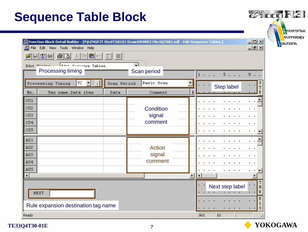
7 YOKOGAWATE33Q4T30-01E
Sequence Table Block
Action signal
comment
Condition signal
comment
Step label
Next step label
Rule expansion destination tag name
Processing timing Scan period
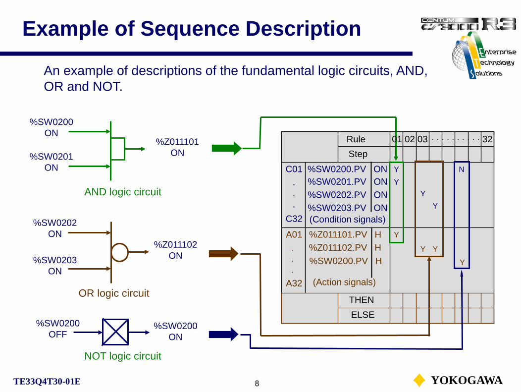
8 YOKOGAWATE33Q4T30-01E
Example of Sequence Description
An example of descriptions of the fundamental logic circuits, AND, OR and NOT.
%SW0200ON
AND logic circuit
OR logic circuit
C01
C32
RuleStep
(Condition signals)
YY
Y
.
.
.
A01
A32
THENELSE
(Action signals)
.
.
.
%Z011101.PV H%Z011102.PV H%SW0200.PV H
Y
YY
Y
%SW0201ON
%SW0202ON
%SW0203ON
%Z011101ON
%Z011102ON
%SW0200OFF
NOT logic circuit
%SW0200ON
N
Y
01 32. . . . . . . . . .02 03
%SW0201.PV ON%SW0202.PV ON
%SW0200.PV ON
%SW0203.PV ON

9 YOKOGAWATE33Q4T30-01E
Non-step Type Sequence Table
C01
C32
A01
A32
THENELSE
RuleStep
(Condition signals)
(Action signals)
Basic operation 1:
(1) As for condition testing, in the same rule number when all conditions (Y or N) are satisfied, the condition of the rule is true.
Y%SW0201%SW0202
%SW0200Y
Y%Z011101%Z011102
N
Y
%SW0203
N
.
.
.
.
.
.
%Z011103 Y(2) Rule columns for the same rule number are all blank are considered true unconditionally.
%SW0200 and %SW0201 are ON and then %Z011101 turns ON.%SW0201 and %SW0202 are OFF and then %Z011102 turns ON.
%Z011103 turns ON unconditionally.
Non-step type sequence table tests all rules at every control period.
01 32. . . . . . . . . .02 03

10 YOKOGAWATE33Q4T30-01E
Non-step Type Sequence Table
Basic operation 2:
When multiple action signals exist in a condition satisfied rule, the actions are executed from top to down.
C01
C32
A01
A32
THENELSE
RuleStep
(Condition signals)
(Action signals)
Y%SW0201%SW0202
%SW0200Y
Y%Z011101%Z011102
%SW0203
.
.
.
.
.
.
%Z011103YN
Actions are executed in order of %Z011101, %Z011102, %Z011103.
01 32. . . . . . . . . .02 03

11 YOKOGAWATE33Q4T30-01E
Execution and Output Timing
Execution timingA sequence table block and a logic chart block have the following four types of execution timing:
• Periodic execution (T):Repeatedly executed in a preset cycle.
• One-shot execution (O):Executed once when invoked by other function blocks.
• Initial execution/Restart execution (I):Executed when the FCS performs a cold or a restart.
• Initial execution (B):Executed when the FCS performs a restart.
Output timingA sequence table block has two types of output timing:• Output only when conditions change (C)• Output each time conditions are satisfied (E)

12 YOKOGAWATE33Q4T30-01E
Output Timing
• Output only when conditions change (C):The action is executed only once when the condition is switched from false to true. However, if the non-latched output is specified for the action signal, the action changes when the condition is switched from true to false.
• Output each time conditions are satisfied (E):The action is executed each control period as long as the condition remains true.
Output only when conditions change (C)
Condition
ON
OFFCondition
ON
OFF
Output
Output each time conditions are satisfied (E)
Output
Non-latched type (L type)

13 YOKOGAWATE33Q4T30-01E
Processing Timing
Execution timing and output timing can be used in combination. The table below shows the combination of timings for ST16 and ST16E.
Default
For the LC64, logic chart block, output timing (C) can not be specified.

14 YOKOGAWATE33Q4T30-01E
Step Type Sequence Table
THENELSE
08RuleStep
YY
Y
C01
C32 (Condition signals)
%SW0201%SW0202
%SW0200
%SW0203
.
.
.
A01
A32 (Action signals)
%Z011101%Z011102.
.
.%Z011103
04 05
0508
Basic operation 1:
For the step type sequence table, the next execution step label must be described in the THEN/ ELSE column in order to advance the steps.
The step will not advance if both next step labels in the THEN/ ELSE are blank. The same step is executed each time.
Step label
Next step label (THEN label)
Next step label (ELSE label)
Step type sequence table tests only rules in the current step at every control period.
YY
YY
Tested rules

15 YOKOGAWATE33Q4T30-01E
Step Type Sequence Table
When the condition of the rule in step 04 is satisfied, the step advances to 05.
Basic operation 2:
The next step specified in the THEN column is the step to advance when the condition test result is true.
After all actions for the corresponding rules are executed, the step proceeds to the next step.
THENELSE
08RuleStep
YY
Y
C01
C32 (Condition signals)
%SW0201%SW0202
%SW0200
%SW0203
.
.
.
A01
A32 (Action signals)
%Z011101%Z011102.
.
.%Z011103
04 05
0508
YY
YY
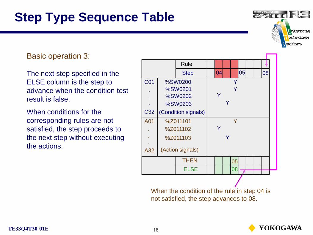
16 YOKOGAWATE33Q4T30-01E
Step Type Sequence Table
Basic operation 3:
The next step specified in the ELSE column is the step to advance when the condition test result is false.
When conditions for the corresponding rules are not satisfied, the step proceeds to the next step without executing the actions.
When the condition of the rule in step 04 is not satisfied, the step advances to 08.
THENELSE
08RuleStep
YY
Y
C01
C32 (Condition signals)
%SW0201%SW0202
%SW0200
%SW0203
.
.
.
A01
A32 (Action signals)
%Z011101%Z011102.
.
.%Z011103
04 05
0508
YY
YY

17 YOKOGAWATE33Q4T30-01E
Step Type Sequence Table
Basic operation 4:
When a step advances to a next step, the next step is executed at the next scan period.
When a step advances, the conditions of each rule are initialized once.
The step sequence executes only a single step at each scan period.In this example, it may take 2 seconds or more to turn %Z011103 OFF, after the step 01 was executed.
C01
C32
A01
A32
THENELSE
04RuleStep
(Condition signals)
(Action signals)
Y%SW0201%SW0202
%SW0200Y
Y%Z011101%Z011102
%SW0203
.
.
.
.
.
.
03
%Z011103 NN
01 02
02 03 04

18 YOKOGAWATE33Q4T30-01E
Step Type Sequence Table
Basic operation 5:
Step label 00 is executed at each period. The step 00 can be described only at the head of a sequence table group. * 1. The step 00 cannot be described as a next step label.
* 2. The step 00 cannot be described on an extended sequence table.
The step 00 as well as the current step 03, conditions are tested. If conditions of step 00 are satisfied, actions are executed.
C01
C32
A01
A32
THENELSE
00 04
RuleStep
(Condition signals)
(Action signals)
Y%SW0201%SW0202
%SW0200Y
Y%Z011101%Z011102
%SW0203
.
.
.
.
.
.
03
%Z011103 N
YY
N
01 02
02 03 04
Current step

19 YOKOGAWATE33Q4T30-01E
Timer Block (TM)
The sequence auxiliary blocks are provided such as a timer, a soft-counter and so on.
Start command
%SW0500.PV ON
TM100.BSTS CTUP
TM100.OP START
Y
Y
Y
N
An example of the timer block operation.
Timer count-up
Stop command
The timer block (TM) measures time in the unit of second or minute.
BSTS: Block statusCTUP: Count-up
OP: OperationSTART: Start/stop action
Timer start/stop
Timer start switch
%SW0500.PV H NStart switch off
Processing Timing: TC

20 YOKOGAWATE33Q4T30-01E
Software Counter Block (CTS)
The software counter block (CTS) counts a number of times that the condition is satisfied.
BSTS: Block statusCTUP: Count-up
ACT: ActionON: Update, OFF: Stop
%SW0502.PV ON
CT100.ACT ON
Y
Y
YCT100.ACT OFF
Update commandStop command
Y
Counter count-up
Counter update
Counter stop
Update switch
%SW0501.PV H N
Processing Timing: TE
An example of the soft-counter block operation.
CT100.BSTS CTUP
%SW0501.PV ONStop switch
%SW0502.PV H
Y
N

21 YOKOGAWATE33Q4T30-01E
Types of Contact Output
Latched (H) type output:The latched type output holds the current output status until ON or OFF operation is executed.
The latched and non-latched type output can also be applied for internal switches, annunciator message outputs and so on.
e.g. %SW0501.PV.H

22 YOKOGAWATE33Q4T30-01E
Types of Contact Output
Non-latched (L) type output:The non-latched type output turns ON when logical computation result becomes true and turns OFF when becomes not true.
OFF action is not effective for the non-latched type output.
e.g. %SW0501.PV.L

23 YOKOGAWATE33Q4T30-01E
Types of Contact Output
Flashing (F) type output:The flashing type output starts flashing when ON operation is executed and stops flashing when OFF operation is executed. In order to turn off the current state, OFF operation as H type is required.
The flashing type output can not be applied for internal switches, annunciator message outputs and so on.
c
e.g. %Z011101.PV.F

1 YOKOGAWATE33Q4T30-01E
Report Functions
CS1000/3000 Fundamental Course Textbook
PART-F Report Functions
F-1 Process Report WindowF-2 Historical Message Report Window

2 YOKOGAWATE33Q4T30-01E
Process Status and Operation RecordThe windows used for confirming the process status are Process Report window and Historical Message Report window. The Process Report window displays the current status of the function blocks and input and output and the Historical Message Report window displays alarms and messages triggered in the past and the operation history.
Window call menu
Process report window call icon
Historical message report window call icon
Toolbar

3 YOKOGAWATE33Q4T30-01E
Process Report WindowThe process report is to collect information on the system operating status and displays it in a window or prints to a printer depending on the user’s request. The current status will be displayed or printed.The following two types of reports are available in the Process Report window.• Tag report• I/O report
Tag report display button
Tag report search button
I/O report display button
I/O report search button

4 YOKOGAWATE33Q4T30-01E
Tag ReportIn a tag report, various statuses such as the function block alarm status, mode and present value of process data are displayed for each element.
The tag report is the real time report of all tags registered in the system. Process alarm generated function blocks, function block under special block mode (AOF, CAL) and so on are confirmed.

5 YOKOGAWATE33Q4T30-01E
Tag Report SearchThe tag report search is done using the Tag Report Search dialog box. Tag names of the following elements can be the object of a tag report.• Function block (%BL)• Annunciator (%AN)• Common switch (%SW)• Process I/O* (%Z)• Global switch (%GS)
There are five tabs in the Tag Report Search dialog box. It is convenient to set frequently used search conditions beforehand.
A data item name can be added to process report window for displaying the data value.
* Among the process I/O, only communication I/O with user-defined tag names can be the object of a tag report.

6 YOKOGAWATE33Q4T30-01E
I/O Report
In the I/O Report, when the data is ON, “1”, and when the data is OFF, “.” (full stop) is displayed.
%SW0001 to %SW0400 are for the system use. (R3.04)
In the I/O report, the I/O status is displayed as a digital value for each element.

7 YOKOGAWATE33Q4T30-01E
I/O Report Search
The station name or element type of the control station can be set as the search conditionsfor the I/O report in the I/O Report Search dialog box.
* %WB is the bit data of the communication input, while %WW is the word data input.
In the I/O report, the I/O status is displayed as a digital value for each element. An I/O report can be searched by station name or element type.The following elements can be the objects of an I/O report:• Annunciator (%AN)• Common switch (%SW)• Communication Input (%WB*)• Communication Input (%WW*)• Process I/O (%Z)

8 YOKOGAWATE33Q4T30-01E
Historical Message Report WindowThe historical message report can retrieve process alarms or the operation history stored within the HIS and display or print messages related to all types of events related to the system or a process that occurred in the past.A historical message can be retrieved and displayed by specifying message type, station name and tag name.
File selection
Redraw
Search
Search pause
File save
Number of displayed messages

9 YOKOGAWATE33Q4T30-01E
Historical Message Save
It is recommended to backup the historical message report as it saves important operation reports and alarm messages.Up to about 80,000 messages are saved in a HDD. If the number of messages exceeds this, the messages will be deleted starting with the oldest ones.If the total number of the messages exceeds 65,536, MS Excel limit warning dialog appears.
The messages are saved in the CSV format for easy utilization.

10 YOKOGAWATE33Q4T30-01E
Historical Message Selection
The long-term data can be referred by specifying the folder where the long-term data are saved.
• File TypeWhen searching for a message that occurred at the time of system generation, select [Engineering History]; when searching for a message that occurred during operation and monitoring, select[Operation and Monitoring Message].• Directory When the historical message save file is stored in the default folder, select [Standard]; when the file is stored in a folder other than the standard, select [Specify Directory].

11 YOKOGAWATE33Q4T30-01E
Historical Message Search
With five tabs, the following items can be specified:• Period specified by date• Specifying message type• Specifying message occurrence source• Specifying user name• Specifying arbitral character
Each of the search conditions is set in the Search dialog box.In the Report Search dialog box, there are five tabs to set up search conditions. Select the tab to set for each search item.
See Supplement VIII. Historical Message Search.

1 YOKOGAWATE33Q4T30-01E
System Maintenance Functions
CS1000/3000 Fundamental Course Textbook
PART-G System Maintenance Functions
G-1 System Status Display WindowG-2 System Alarm WindowG-3 Adjust Time Dialog BoxG-4 HIS Setup Window

2 YOKOGAWATE33Q4T30-01E
System Maintenance FunctionsThe windows displaying the online system status and the system alarm status and so on are provided with operation environment to support system maintenance.

3 YOKOGAWATE33Q4T30-01E
System Status Overview Window
System alarm window button
The System Status Overview window displays the status of all stations and the communication buses in the V net comprising the system. The status of the connected stations and the V net may be visually confirmed by icon displays. Also, other system maintenance windows may be called up from this window.
HIS setup button
FCS0101 normal
FCS0102 communication error
V-net 2 error
V-net 1 normal
HIS0123 normal
Present station display(White background color)
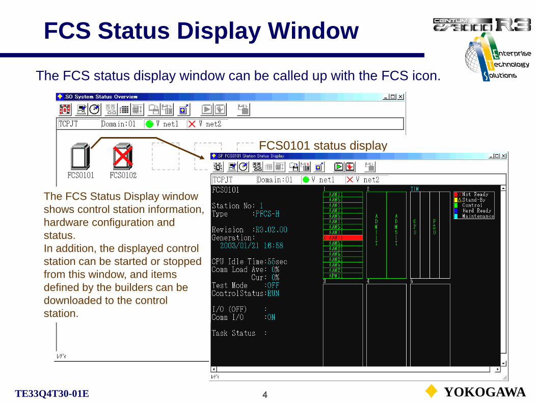
4 YOKOGAWATE33Q4T30-01E
FCS Status Display Window
The FCS status display window can be called up with the FCS icon.
FCS0101 status display window
The FCS Status Display window shows control station information,hardware configuration and status. In addition, the displayed control station can be started or stopped from this window, and items defined by the builders can be downloaded to the control station.

5 YOKOGAWATE33Q4T30-01E
FCS Status Display WindowIcons for SFCS status display window.
FCS report
IOM download
FCS start
FCS stop
Tuning parameter save

6 YOKOGAWATE33Q4T30-01E
System Alarm WindowThe System Alarm window displays system alarm messages to notify the user of system hardware (FCS down, card error etc.) in the order with the most recent ones first. When an alarm occurs, the alarm starts to buzz, and the button in the System Message window and the LED for the system key on the operation keyboard begin to flash.
System status overview display
Updating retained for 5 seconds
Filter dialog
System alarm overview

7 YOKOGAWATE33Q4T30-01E
Adjust Time Dialog Box
Adjust Time dialog box sets and changes the date and time of system in the domain.The date and time set in the dialog box are applied to the machines shown below.• All the control stations in the same domain• All HIS in the same domain

8 YOKOGAWATE33Q4T30-01E
HIS Setup Window
● Station● Printer● Buzzer● Display● Window switching● Control bus ● Alarm● Preset menu● Equalize● Function Keys
● Operation mark● Multimedia● Long term● External recorder● OPC● Report● Monitors● Process management● Navigator
Some of the tab sheets may not be displayed according to the installed package.The tab sheets with are explained. See Supplement IX. HIS Setup Window.
The HIS Setup window is used for displaying and changing the current station’s information and operation settings.The HIS Setup window can perform settings specific to the HIS such as the operation and monitoring window display size setting, printer setup and operation panel mode setting.The tabs provided for each setting item are:

9 YOKOGAWATE33Q4T30-01E
Display Tab Sheet
Operation screen mode switching
Settings such as the operation screen mode and toolbar button size are displayed in the Display tab. The contents of the settings can also be changed.
Font name and size switching

10 YOKOGAWATE33Q4T30-01E
Window Switching Tab SheetIn the Window Switching tab, the display size of the operation and monitoring windows called up from the System Message window, whether automatic window switching is enabled at the time a process alarm or an operator guide message is generated, etc., are displayed. The setup items can also be changed.
Window switching setup
Dynamic window setup

11 YOKOGAWATE33Q4T30-01E
Preset Menu Tab SheetIn the HIS, there is a function that allows frequently used functions to be called up easily.By presetting the functions to be called in the Preset Menu tab, they can be called up from the System Message window.Up to 32 functions can be set.
Overview of defined preset menu and defining functions

12 YOKOGAWATE33Q4T30-01E
Function Keys Tab SheetThe function key assignments defined in the Function Key Assignment Builder are displayed in the Function Keys tab. Also, the function key assignment can be defined temporarily.
The function of the function keys can be changed temporarily.
(If the function key definition file is downloaded, that file replaces the current file.)
See Supplement XI. Function Key Function Assignment.

13 YOKOGAWATE33Q4T30-01E
Operation Mark Tab SheetThe operation marks which are defined in the Operation Mark Builder are displayed in the Operation Mark tab. Also, the label comment color of the operation mark may be defined temporarily, as well.
Color and labels can be changed temporarily.
(If the operation mark definition file is downloaded, that file replaces the current file.)

1 YOKOGAWATE33Q4T30-01E
Security Policy
CS1000/3000 Fundamental Course Textbook
PART-H Security Policy
H-1. Security OverviewH-2. HIS SecurityH-3. User SecurityH-4. User GroupH-5. Window AuthoritiesH-6. Mode Selection KeyH-7. Function Block SecurityH-8. Operation Mark

2 YOKOGAWATE33Q4T30-01E
Security Overview (1)
In the CS 1000/CS 3000 security policy, “operation and monitoring” is defined as follows:
• OperationSetting data to function blocks, changing function block status and other operations.
• MonitoringDisplaying function block data, acknowledgment of received messages and alarms or calling up windows.
The security policy is set to prevent illegal operations and other problems and ensuring the safety of the system.The security policy restricts the scope of operation and monitoring permitted for an operator, and masks certain alarms of which the operator need not be notified.
3 YOKOGAWATE33Q4T30-01E
Security Overview (2)
General-purpose Windows applications follow the security policy of Windows. The user of CENTUM is different from the user of Windows.
The following two types of policies are available in CS 1000/CS 3000.• HIS Security PolicyHIS security policy stipulates the scope of operation and monitoring allowed on the Human Interface Station. Regardless of the logon users, the operation performed to a device or to a function block data item may be restricted.
• User Security PolicyUser security policy stipulates the scope of operation and monitoring for the users.Each user is restricted to operate or monitor a certain scope of devices and function block data items.
The scope of operation and monitoring permitted for an operator is determined by a combination of HIS security and user securitysettings.

4 YOKOGAWATE33Q4T30-01E
Flow of Security Check
HIS operation
HIS security check
Scope of operation and monitoring
check for the HIS
User security check
• Window operation and monitoring• Function block operation and monitoring Operation record
OperationHistory
Security check
Operation
Scope of operation and monitoring
check for a user group
Privilege levels of operation and monitoring check
for a user

5 YOKOGAWATE33Q4T30-01E
HIS Security
The security level setting means to select either monitoring only machine or monitoring and operation machine (default).
The security level regarding operation and monitoring as well as the operation and monitoring scope can be set for the HIS itself. The HIS security check has a precedence over the user security check. The operation and monitoring scope of the HIS is unrelated with the operation and monitoring scope set for each user group.

6 YOKOGAWATE33Q4T30-01E
User Security
User name: User recognitionPassword: User identificationUser group: Monitoring and operation scopePrivilege level: Monitoring and operation authority
The operations performed by the user are held as the operation record. The operation record can be confirmed by the historical message report.
The operators performing the operation and monitoring functions are classified based on their privilege level (authority). This classification is called user.
The following attributes are assigned to each user:

7 YOKOGAWATE33Q4T30-01E
User Privilege Levels
*1 Maintenance means the engineering work such as initiation of the builder.
The users’ operation and monitoring rights on HIS are defined according to privilege levels.For each window, operation and monitoring rights can be defined. Whether the user with a certain privilege level is permitted to operate the specified data item can also be defined. The following default privilege levels are available (security level 4).
See Supplement X. Function Block Security.
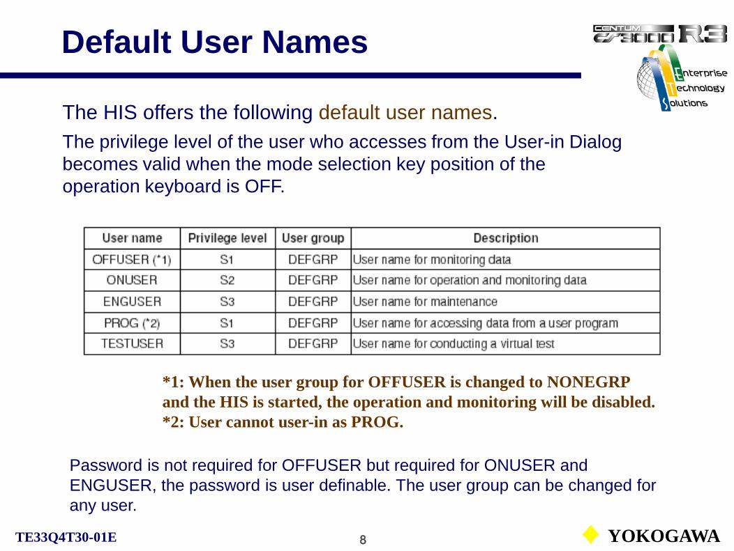
8 YOKOGAWATE33Q4T30-01E
Default User Names
The HIS offers the following default user names.The privilege level of the user who accesses from the User-in Dialog becomes valid when the mode selection key position of the operation keyboard is OFF.
*1: When the user group for OFFUSER is changed to NONEGRP and the HIS is started, the operation and monitoring will be disabled.*2: User cannot user-in as PROG.
Password is not required for OFFUSER but required for ONUSER and ENGUSER, the password is user definable. The user group can be changed for any user.
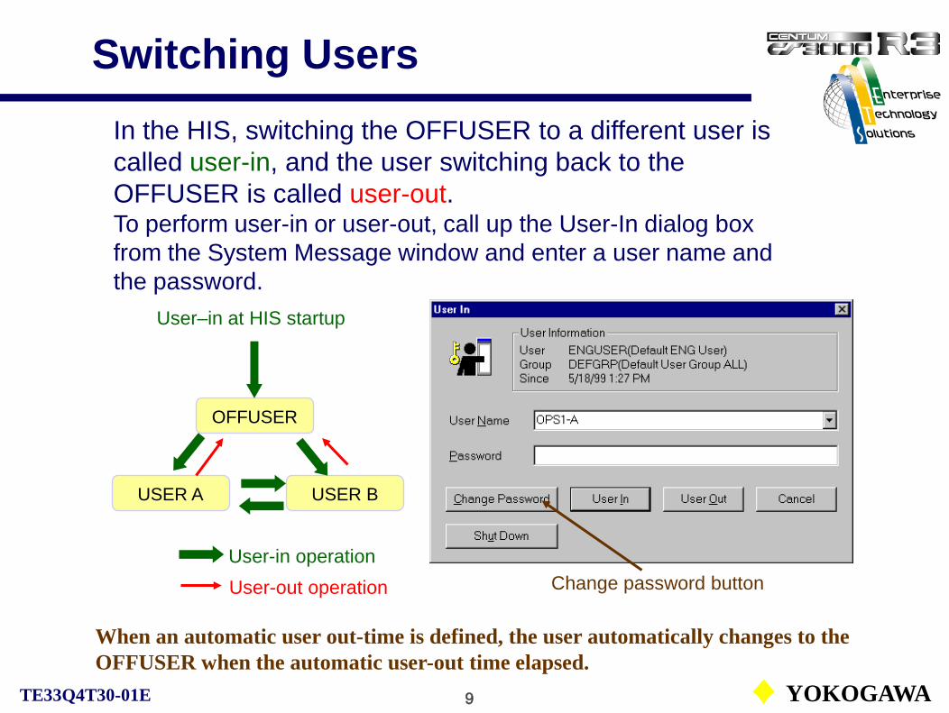
9 YOKOGAWATE33Q4T30-01E
Switching UsersIn the HIS, switching the OFFUSER to a different user is called user-in, and the user switching back to the OFFUSER is called user-out.To perform user-in or user-out, call up the User-In dialog box from the System Message window and enter a user name and the password.
Change password button
OFFUSER
USER A USER B
User-in operationUser-out operation
User–in at HIS startup
When an automatic user out-time is defined, the user automatically changes to the OFFUSER when the automatic user-out time elapsed.

10 YOKOGAWATE33Q4T30-01E
User Group
The following attributes are assigned to each user group:
• User group name: User group recognition• Monitoring scope: Monitoring range• Operation and monitoring scope: Operation and monitoring range• Windows scope: Window names for operation and monitoring• Acknowledgement: Acknowledgment range • Process message receiving: Monitoring range of the generated messages
The range is set by the plant name. If the plant name is not used, set by the station name and the control drawing.
The users are classified into groups based on their operation and monitoring scopes. This classification is called user group.

11 YOKOGAWATE33Q4T30-01E
Default User Group
The following built-in default user groups are managed by CS 1000/CS 3000 security policy.
The user group name may be defined on the Security Builder.

12 YOKOGAWATE33Q4T30-01E
Concepts of Scope and Privilege
Operation & monitoring scope of users, OPS*-A in Group-AB using HIS0124 and their privileges.
Operation & monitoring scope of HIS0124.
EquipmentA
Users in Group-AB:OPS1-A: OPS2-A: OPS3-A:
Whole Plant
EquipmentB
EquipmentC
EquipmentD
EquipmentE
Operation & monitoring scope of user Group-AB.
MonitoringOperation and monitoringOperation, monitoring and maintenance
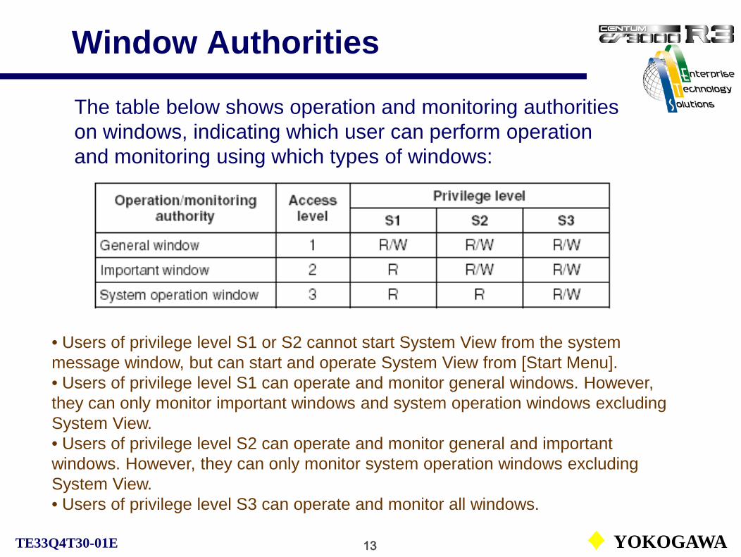
13 YOKOGAWATE33Q4T30-01E
Window Authorities
The table below shows operation and monitoring authorities on windows, indicating which user can perform operation and monitoring using which types of windows:
• Users of privilege level S1 or S2 cannot start System View from the system message window, but can start and operate System View from [Start Menu].• Users of privilege level S1 can operate and monitor general windows. However, they can only monitor important windows and system operation windows excluding System View.• Users of privilege level S2 can operate and monitor general and important windows. However, they can only monitor system operation windows excluding System View.• Users of privilege level S3 can operate and monitor all windows.

14 YOKOGAWATE33Q4T30-01E
Function Block Security
The attributes of function blocks contain security levels, tag mark types and alarm processing levels. The attributes can be defined to each function block in engineering. There is no restriction on the combination of security levels, tag mark types and alarm processing levels.
The tables on operation and monitoring authority are fixed and cannot be edited.
The tables below show the relationship of the function block’s data items and the privilege levels in operation and monitoring rights.
R: Monitoring W: Operation
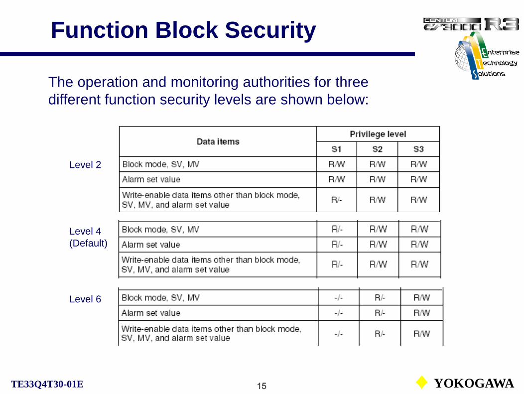
15 YOKOGAWATE33Q4T30-01E
Function Block Security
The operation and monitoring authorities for three different function security levels are shown below:
Level 2
Level 6
Level 4(Default)

16 YOKOGAWATE33Q4T30-01E
Mode Selection Key
In the case of the operation key When the engineering key is selected.Changes between The key can be switched
the ON, OFF positions. to any position.
The following two mode selection keys are used to switch the security level:
When the HIS is connected with an operation keyboard, the privilege level of the user may be changed temporarily using the mode selection key on the keyboard. The privilege level changed on the keyboard has higher priority than the level set in the user-in dialog box.
• Operation key (Privilege level S2)The key can be switched between the ON and OFF positions only.• Engineering key (Privilege level S3)The key can be switched to any position.
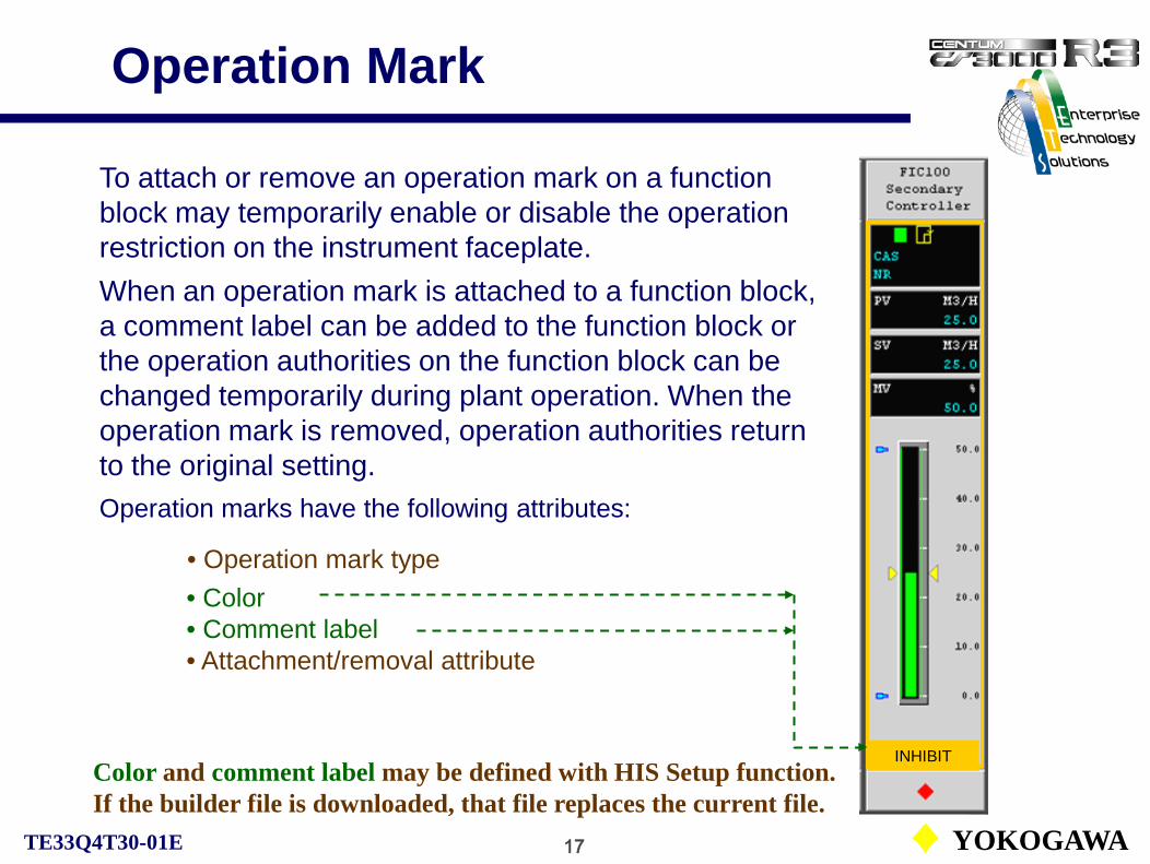
17 YOKOGAWATE33Q4T30-01E
Operation Mark
To attach or remove an operation mark on a function block may temporarily enable or disable the operation restriction on the instrument faceplate. When an operation mark is attached to a function block, a comment label can be added to the function block or the operation authorities on the function block can be changed temporarily during plant operation. When the operation mark is removed, operation authorities return to the original setting.Operation marks have the following attributes:
• Operation mark type• Color• Comment label• Attachment/removal attribute
INHIBITColor and comment label may be defined with HIS Setup function. If the builder file is downloaded, that file replaces the current file.
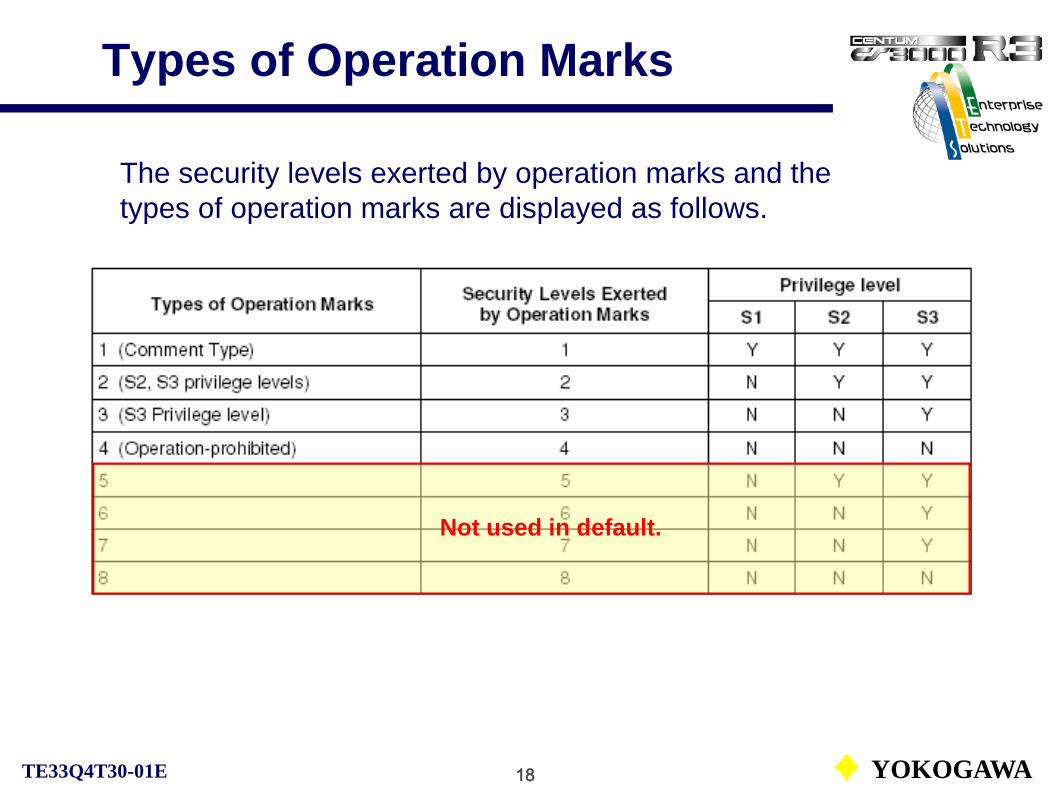
18 YOKOGAWATE33Q4T30-01E
Types of Operation Marks
The security levels exerted by operation marks and the types of operation marks are displayed as follows.
Not used in default.

19 YOKOGAWATE33Q4T30-01E
Install or Remove Operation Mark
The unauthorized user is prohibited to install / remove the operation mark. The setting of installing/removing is performed in Operation Mark Builder.
The relationship between user’s privilege level and the operation rights on installing/removing mark authority is shown below:

1 YOKOGAWATE33Q6C40-01E
FCS Common
CS1000/3000 Engineering Course Textbook
PART-A
FCS Common

2 YOKOGAWATE33Q6C40-01E
FCS Common
Reference: IM33S01B30-01EField Control Station PART-A FCS Common
CS1000/3000 Engineering Course TextbookPART-A FCS Common
A1. FCS Basic DefinitionA2. FCS Function OverviewA3. I/O Functions of FCS
A3.1. Process I/OA3.2. Software I/O

3 YOKOGAWATE33Q6C40-01E
FCS Basic Definitions
CS1000/3000 Engineering Course Textbook
PART-A 1
FCS Basic Definition

4 YOKOGAWATE33Q6C40-01E
FCS Property
Station type definition:Select the FCS station type for use from the station type list.
On the creation of FCS, define FCS type, station number, database type and so on with the property window.
Station number
See GS and IM for details of FCS types.
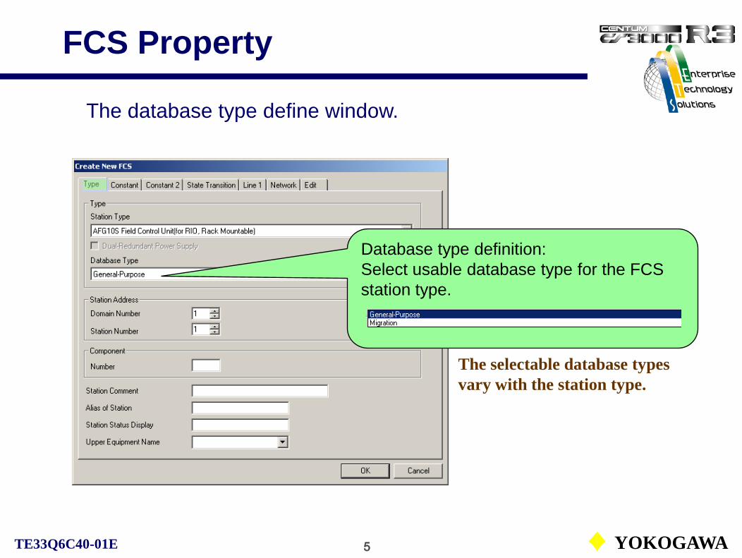
5 YOKOGAWATE33Q6C40-01E
FCS Property
The database type define window.
Database type definition:Select usable database type for the FCS station type.
The selectable database types vary with the station type.

6 YOKOGAWATE33Q6C40-01E
FCS Database Types
Examples of usable number of function blocks and elements for the database types:
Database type (LFCS)
General purpose
Regulatory monitoring
Sequence monitoring
Sequential control
Regulatory control / calculation blocks 700 2000 300 400
Sequence blocks 450 200 200 600
Switch instruments 450 450 2000 1000
See Supplement III. FCS Database Types.

7 YOKOGAWATE33Q6C40-01E
FCS Property
The high speed scan periods and the network protocols are defined by FCS property dialog.
Scan period setting for the high speed scan. (Common for function blocks)
Control network protocolUse default settings. No change is allowed.

8 YOKOGAWATE33Q6C40-01E
FCS ConstantsDetailed definitions of the FCS can be set with the StnDef (FCS constants builder) file in the CONFIGURATION folder.
FCS constants builder defines wind-up time (a preparatory processing for organizing time-series data), repeated warning alarm period and so on.

9 YOKOGAWATE33Q6C40-01E
FCS Constants
The window that defines the FCS start conditions.
Selection of the start conditions and setting of detection time for the momentary power failure. (effective only for TIME start condition.)
FCS constants cannot be online downloaded.

10 YOKOGAWATE33Q6C40-01E
FCS Start Conditions
Start condition Start operation
MAN (Initialized start)
Initialized start
TIME (Restart at momentary power failure)
Prolonged power failure
Momentary power failure
Restart
AUTO (Restart)
When FCS starts at the time of power recovery after the power failure, the condition either initialized start or restart is referred to as the start condition.
Three selectable conditions are available:
(Momentary power failure detection time < Power failure time)
(Momentary power failure detection time > Power failure time)

11 YOKOGAWATE33Q6C40-01E
Flow of FCS Start
RestartInitialized start
Start processing from the beginning of periodic processing.
Continue processing from the discontinued point.

12 YOKOGAWATE33Q6C40-01E
FCS Start Processing
Initialized Start Restart
System initialization processing System initialization processing
User defined initialization processing*
Finish the discontinued function block processing by power failure
Wind-up operation** User defined initialization processing
Start processing from the beginning of periodic processing.
Continue processing from the discontinued point.
Two types of start processing:
* User definition initialization processing: The processing timing of initialization start (B) or initialization start and restart (I) that is specified on sequential control blocks.
** Wind-up operation: Windup operation is a preparatory processing for organizing time-series data that are required for control operations.

13 YOKOGAWATE33Q6C40-01E
FCS Function Overview
CS1000/3000 Engineering Course Textbook
PART-A 2
FCS Function Overview

14 YOKOGAWATE33Q6C40-01E
Configuration of FCS FunctionsFCS control functions consist of the basic control functions, the software I/O functions and I/O interface functions. The basic control functions have various function blocks that perform control computations. The I/O interfaces include the process I/O and other interface functions.
FCS
Basic control Software I/O
I/O interfaces

15 YOKOGAWATE33Q6C40-01E
The function blocks, which are the minimum elements consisting the basic control function, and the control drawings, which connect multiple function blocks, configure the FCS control functions hierarchically.
Function block
TIC100
PIDControl drawing
Function Block and Control Drawing

16 YOKOGAWATE33Q6C40-01E
Function BlockFunction block:The function block is the minimum element that executes control computations.Regulatory control blocks, sequential control blocks, computation blocks, SFC blocks are the function blocks. The control functions can be described like an instrumentation flow sheet by connecting regulatory control, sequential control and computation blocks.Every function block should have a tag name and be stated on a control drawing.
Function blocks(Regulatory control, Computation, Sequential control)
FIC100
PID
ST22-A
ST16
TIM201
TM
CU201
CALCU
TI100
PVI
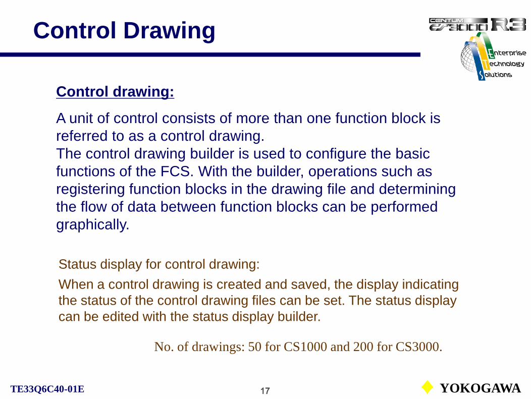
17 YOKOGAWATE33Q6C40-01E
Control Drawing
Control drawing:
A unit of control consists of more than one function block is referred to as a control drawing.The control drawing builder is used to configure the basic functions of the FCS. With the builder, operations such as registering function blocks in the drawing file and determining the flow of data between function blocks can be performed graphically.
No. of drawings: 50 for CS1000 and 200 for CS3000.
Status display for control drawing:When a control drawing is created and saved, the display indicating the status of the control drawing files can be set. The status display can be edited with the status display builder.

18 YOKOGAWATE33Q6C40-01E
Control Drawing
Regulatory control blocks
Sequential control blocks
Calculation blocks
FCS
Control drawing
Regulatory control functions
Calculation functions
Sequential control functions
CS1000/CS3000The features of the control drawing are as follows:
1) A single control drawing can include different types of function blocks, like regulatory control blocks and sequential control blocks.
2) No restrictions of signal transmission between control drawings. A function block can be connected to the function block on another control drawing.

19 YOKOGAWATE33Q6C40-01E
Control Drawing
No restrictions of signal transmission between the control drawings.
FCS0101
AREAIN block connection
FCS0102
AREAOUT block connectionDR0012
DR0001 DR0002 DR0025 DR0050
DR0013

20 YOKOGAWATE33Q6C40-01E
Control DrawingIn order to add or edit function blocks, click on the control drawing file (DRnnnn) in the FUNCTION_BLOCK folder.
Control drawing
To edit a status display, click on the DISPLAY folder and then the control drawing.

21 YOKOGAWATE33Q6C40-01E
I/O Functions of FCS (Process I/O)
CS1000/3000 Engineering Course Textbook
PART-A 3
I/O Functions of FCSA3.1. Process I/O

22 YOKOGAWATE33Q6C40-01E
FCS
I/O Functions of FCS
The software I/O is the virtual I/O realized by the FCS software. Data setting or data reference to or from other function blocks or applications is possible.
The I/O interfaces can handle not only process I/O but also sub-system I/O as PLC and fieldbus I/O.
Basic control Software I/O
I/O interfaces

23 YOKOGAWATE33Q6C40-01E
Process I/O
See IM33S01B30-01E PART-A FCS Common, A3 Process Inputs/Outputs.
By combining the I/O module with a barrier, an intrinsically safe loop can be constructed.
The process I/Os are shown below:
Analog input:Current input, voltage input, mV input, TC input, RTD input, potentiometer input, pulse train input.
Analog output:Current output, voltage output.
Contact input:Contact ON/OFF input signals from field devices to the FCS. Two types of signals exist; status signals and push button signals.
Contact output:Contact ON/OFF output signals from the FCS to field devices.(The status output signals of a status type I/O module can be manipulated in the following styles:Latched type, non-latched type, pulse type and flashing type output.)

24 YOKOGAWATE33Q6C40-01E
Types of Contact OutputLatched (H) type output:The latched type output holds the current output status until ON or OFF operation is executed.
The latched and non-latched type output can also be applied for internal switches, annunciator message outputs and so on.

25 YOKOGAWATE33Q6C40-01E
Types of Contact OutputNon-latched (L) type output:The non-latched type output turns ON when logical computation result becomes true and turns OFF when becomes not true.
OFF action is not effective for the non-latched type output.

26 YOKOGAWATE33Q6C40-01E
Types of Contact Output
Pulse (P) type output:The pulse type output turns ON for only one scan cycle when logical computation result becomes true. After one scan cycle, it turns OFF.
OFF action is not effective for the pulse type output.

27 YOKOGAWATE33Q6C40-01E
Types of Contact OutputFlashing (F) type output:The flashing type output starts flashing when ON operation is executed and stops flashing when OFF operation is executed. In order to turn off the current state, OFF operation as H type is required.
The flashing type output can not be applied for internal switches, annunciator message outputs and so on.
c

28 YOKOGAWATE33Q6C40-01E
I/O Module Definition
The necessary process I/O modules are installed to the FCS. Types and installation positions the of the installed I/O modules should be defined before using the I/O modules.
See IM33S01B30-01E PART-F Engineering, F1.5 Creating New IOM.
The types of the I/O modules can be used may differ on the FCS station types and I/O bus types.
When the FCS consists of multiple nodes, create the node that installs the I/O modules before creating the I/O modules.
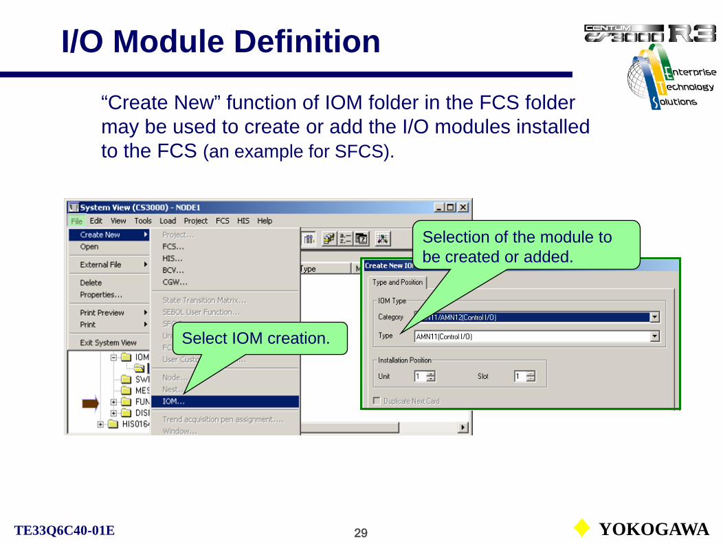
29 YOKOGAWATE33Q6C40-01E
I/O Module Definition
Select IOM creation.
“Create New” function of IOM folder in the FCS folder may be used to create or add the I/O modules installed to the FCS (an example for SFCS).
Selection of the module to be created or added.

30 YOKOGAWATE33Q6C40-01E
Select the type of module nest from the list.
I/O Module Definition
I/O module definition dialog (an example for SFCS).
Unit installation position
Slot installation position
Select the type of I/O module from the list.

31 YOKOGAWATE33Q6C40-01E
I/O Module Definition
For each I/O module in the analog I/O nest, definitions of input signal type, signal conversion, range and so on are required.
For each contact I/O module terminal, definitions of tag name, switch position label, button color and so on are required.

32 YOKOGAWATE33Q6C40-01E
I/O Module Definition
IOP detection
Square-root extraction
Detailed setting items related to the hardware for each I/O module can be defined with ‘Set details’ dialog on the ‘Tool’ tab.(IOP detection, OOP detection, square root extraction and so on.)
See IM33S01B30-01E PART-A FCS Common, A3 Process Inputs/Outputs.
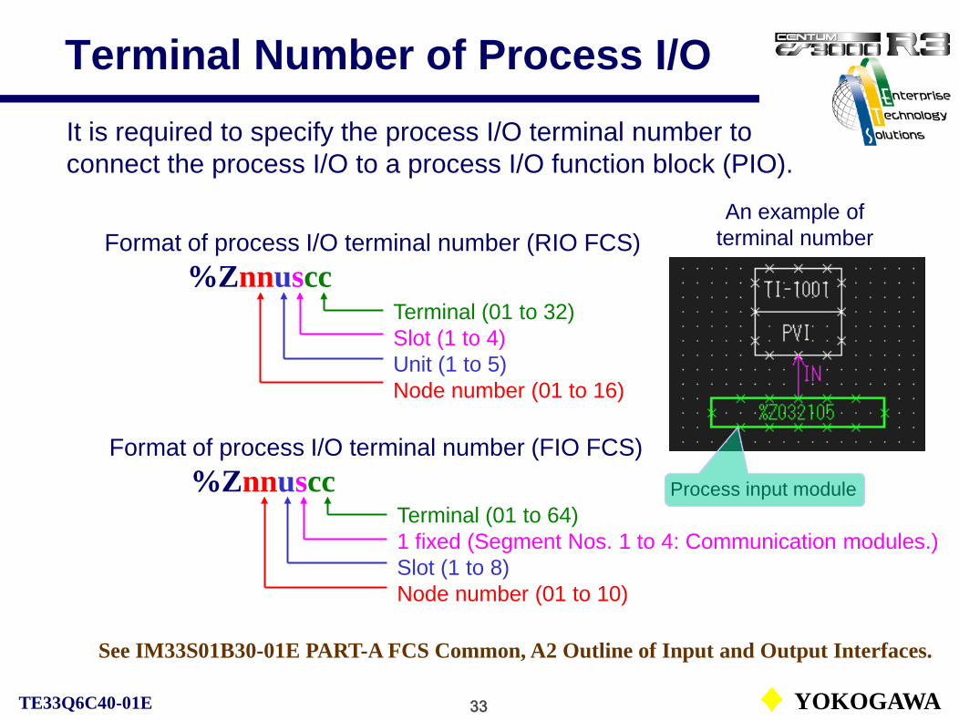
33 YOKOGAWATE33Q6C40-01E
Terminal Number of Process I/O
Format of process I/O terminal number (RIO FCS)%Znnuscc
Terminal (01 to 32)Slot (1 to 4)Unit (1 to 5)Node number (01 to 16)
An example of terminal number
See IM33S01B30-01E PART-A FCS Common, A2 Outline of Input and Output Interfaces.
It is required to specify the process I/O terminal number to connect the process I/O to a process I/O function block (PIO).
Process input module
Format of process I/O terminal number (FIO FCS)%Znnuscc
Terminal (01 to 64)1 fixed (Segment Nos. 1 to 4: Communication modules.)Slot (1 to 8)Node number (01 to 10)

34 YOKOGAWATE33Q6C40-01E
Terminal Number of Process I/O
The meaning of the parameter nnuscc indicating the installation position differs on the types of the FCS:
• RIO bus (RIO system) LFCS (SFCS, PFCS inclusive)• ESB bus (FIO system) KFCS
The FCS builder is common for all types of FCS. The differences lie only on IOM installation specifications and the process I/O terminal specifications. Other specifications are independent to the hardware. Not necessary to consider the type of FCS in engineering.
An example of terminal number

35 YOKOGAWATE33Q6C40-01E
I/O Functions of FCS (Software I/O)
CS1000/3000 Engineering Course Textbook
PART-A 3
I/O Functions of FCSA3.2. Software I/O

36 YOKOGAWATE33Q6C40-01E
Basic control Software I/O
I/O interfaces
Roles of Software I/O
The software I/O may be used for operation tests and for status operations in the sequential control.

37 YOKOGAWATE33Q6C40-01E
Software I/O
Types of software I/O:
• Internal switch:The internal switches exchange logical values between function blocks or applications.
• Message output:The message that transmits the occurrence of events.
The software I/O enables data setting or data reference to or from other function blocks or applications same as in the process I/O.

38 YOKOGAWATE33Q6C40-01E
Examples of Using Software I/O
Heating start
TIC101
PID
FIC101
PID
Sequence operations like SV setting, block mode switching in a regulatory control.
An internal switch latched output for the graphic display modify.
Operator guide message output
Internal switch (Start switch) Message Output
Reactor A charge end
Heating
14:05 Reactor A heating start
Annunciator message output

39 YOKOGAWATE33Q6C40-01E
Data Formats of Software I/O
The table below shows data formats of the software I/O:
See IM33S01B30-01E PART-A FCS Common, A4 Software Inputs/Outputs.
As the status is saved in the FCS as bit data, they can be used for condition signals (input) in the sequential control.

40 YOKOGAWATE33Q6C40-01E
Software I/O Output Destination
The table below shows the output destinations of the software I/O:
: Message outputs often used.

41 YOKOGAWATE33Q6C40-01E
Internal SwitchesThe internal switch (Global switches and Common switches) definition files are in the SWITCH folder in the FCS folder. Define them before use.
Common switch definition files
Global switch definition file

42 YOKOGAWATE33Q6C40-01E
Common Switches (%SW)
The common switches are one of internal switches shared by various control functions in the FCS to hold logical values. The common switches do not output the logical values. The control functions execute condition testing or status manipulation of the switches.
Condition testing%SWnnnn.PV ON/OFF nnnn: Element number
Status manipulation%SWnnnn.PV H/L H = Latched output
L = Non-latched output
For CS1000: %SW0201 - %SW1000 for user’s use.For CS3000: %SW0401 - %SW4000 for user’s use

43 YOKOGAWATE33Q6C40-01E
Common Switches for System
The common switches for the system use are the common switches from %SW0001 to %SW0400 exclusively used for the system. Users, however, can refer their status.
The system use common switches from %SW0001 to %SW0007 are used to distinguish the start conditions of the FCS. The users can refer the switches as the condition testing for the initialization of the sequential control.
For CS1000 and CS3000 up to R 3.03: Up to %SW0200.
See IM33S01B30-01E PART-A FCS Common, A4.1 Common Switch.

44 YOKOGAWATE33Q6C40-01E
Global Switches (%GS)
The global switches share the same logical values between all stations in a system (same domain).
Any applications in the station can read and write the global switch status of the own station.
FCSStation2(R)
FCSStation1(R/W)
FCSStation2(R/W)
FCSStation1(R)
FCS01 FCS02
V net
Link transmission
R: Read enabled
Only CS3000 and CS1000 enhanced type can use the global switches.
W: Write enabled

45 YOKOGAWATE33Q6C40-01E
Using Global Switches
The global switches can be effectively used for sending signals to or referring the status of control equipment in other control stations.
FCS01Boiler control
FCS02Equipment 1A
control
Global switches of FCS02
Setting
Reference
Reference
Global switches of FCS01
Request to start sub-boiler
Sub-boiler operating
Sub-boiler abnormal
Setting
Setting
Reference

46 YOKOGAWATE33Q6C40-01E
Scan Transmission Definition
To transfer or receive the values of global switches between stations, define scan transmission with the FCS constants definition builder. (Default setting is no transmission.)
Transmission for individual station.
Buffer size setting (32 bytes fixed).
FCS constants definition window
Buffer size setting on stations to transmit (32 bytes fixed).

47 YOKOGAWATE33Q6C40-01E
Global Switches
The formats for condition testing and status manipulation of the global switches are shown below: (Station number for the status manipulation is omitted as the manipulation is only possible for the own station.)
Condition testing%GSnnnmm.PV ON/OFFnnn: Element number (001 – 256)mm: Station number (can be omitted for the own station)
Status manipulation%GSnnn.PV H/L H = Latched output
L = Non-latched output

48 YOKOGAWATE33Q6C40-01E
Message OutputsThe definition files of the message outputs (annunciator messages, operator guide messages and so on) are in MESSAGE folder in the FCS folder. Define them before use.
Operator guide message definition file
Annunciator message definition file

49 YOKOGAWATE33Q6C40-01E
Annunciator Messages (%AN)
The annunciator messages (%AN) realize the function of an annunciator panel on the instrumentation panel by the software. Different from other messages, the annunciator messages hold the status for the alarm occurrence as the logical values.
Condition testing%ANnnnn.PV ON/OFF nnnn: Element number
Status manipulation%ANnnnn.PV H/L H = Latched output
L = Non-latched output
CS1000: %AN0001 to %AN0200 are available.CS3000: %AN0001 to %AN1000 are available

50 YOKOGAWATE33Q6C40-01E
Annunciator Message (%AN)
The alarm processing levels can be defined for each annunciator message. The relations between the alarm processing levels and the alarm state transitions are as follows:
• High-priority alarm: Lock type, Repeated warning alarm provided• Medium-priority alarm: Lock type• Low-priority alarm: Non-lock type• Logging alarm: Self-acknowledge type
Alarm processing level setting
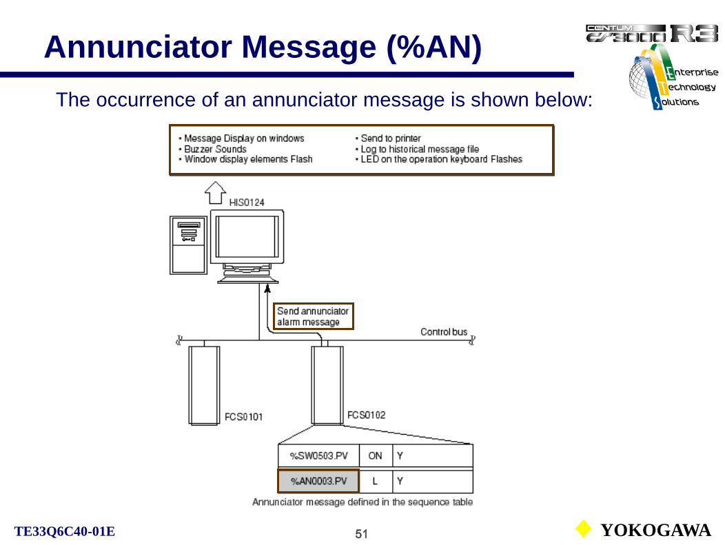
51 YOKOGAWATE33Q6C40-01E
Annunciator Message (%AN)The occurrence of an annunciator message is shown below:

52 YOKOGAWATE33Q6C40-01E
Annunciator Message
Alarm priority levels and state transitions of the annunciator message. Occurrence
Recovery Occurrence
Acknowledgement
Recovery
Re-warning
Lock type (High and medium-priority alarms)
Alarm absent state
Flashing OFF
Alarm absent state
Flashing ON
Alarm present state
Flashing OFF
Alarm present state
Flashing ON
Acknowledgement

53 YOKOGAWATE33Q6C40-01E
Annunciator Message
Alarm priority levels and state transitions of the annunciator message. Occurrence
Re-warning
Acknowledgement
Recovery
Non-lock type (Low-priority alarm)
Recovery
Alarm absent state
Flashing OFF
Alarm present state
Flashing OFF
Alarm present state
Flashing ON

54 YOKOGAWATE33Q6C40-01E
Annunciator Message
Alarm priority levels and state transitions of the annunciator message.
Self-acknowledgement type (Logging alarm)
Recovery
Alarm absent state
Flashing OFF
Alarm present state
Flashing OFF
Occurrence

55 YOKOGAWATE33Q6C40-01E
Re-warning Alarm
The re-warning alarm function for the annunciator message output is provided to output the message again if the alarm condition continues existing over the set period (time-repeated warning) regardless of the operator’s acknowledgement.
Re-warning alarm cycle setting in FCS constants definition file. The two types of the re-warning functions are available:
• Timer-repeated warning:Time repeated warnings are forhigh-priority alarm.
• Event-repeated warning:Event repeated warnings canbe applied regardless of the alarm priority. Re-warning alarm cycle: 0 to 3600 seconds.
Default setting is 600 seconds.
See IM33S01B30-01E PART-A FCS Common, A4.3 Annunciator Message Output.
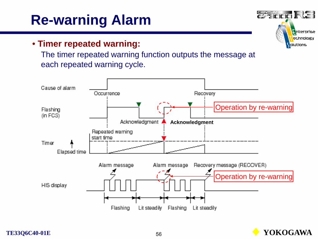
56 YOKOGAWATE33Q6C40-01E
Re-warning Alarm• Timer repeated warning:
The timer repeated warning function outputs the message ateach repeated warning cycle.
Operation by re-warning
Operation by re-warning
Acknowledgment
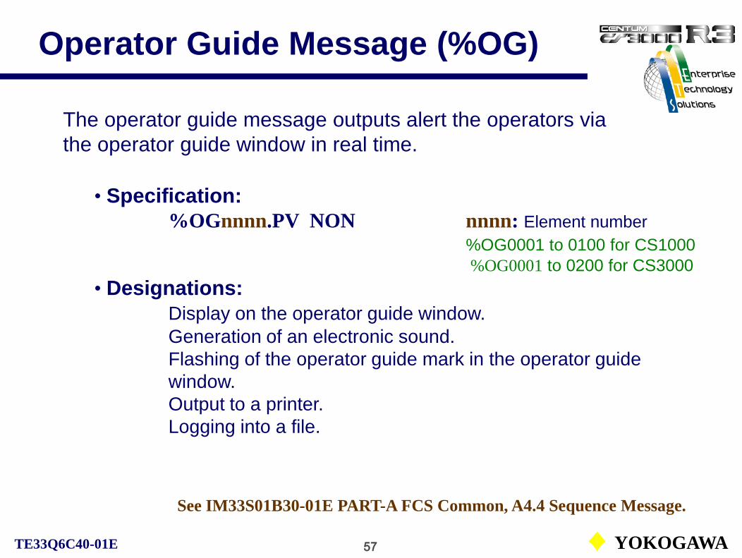
57 YOKOGAWATE33Q6C40-01E
Operator Guide Message (%OG)
• Specification:%OGnnnn.PV NON nnnn: Element number
%OG0001 to 0100 for CS1000%OG0001 to 0200 for CS3000
• Designations:Display on the operator guide window.Generation of an electronic sound. Flashing of the operator guide mark in the operator guidewindow.Output to a printer.Logging into a file.
The operator guide message outputs alert the operators via the operator guide window in real time.
See IM33S01B30-01E PART-A FCS Common, A4.4 Sequence Message.
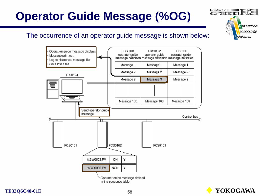
58 YOKOGAWATE33Q6C40-01E
Operator Guide Message (%OG)The occurrence of an operator guide message is shown below:

59 YOKOGAWATE33Q6C40-01E
Message Output Functions
See IM33S01B30-01E PART-A FCS Common, A4.4 Sequence Message.
The message output functions for sequential controls are used to alert operators or to notify events to other applications.
Printout Logging Other functions
Printout message output (%PR) Yes Yes Printout with messages
Operator guide message output (%OG) Yes Yes Electronic sounds, display
Multi-media function start message output (%VM) No Yes Multi-media function start
Sequence message request (%RQ) No Yes Startup HIS functions
Supervisory computer message output (%M3) No No Event message output
Signal event message output (%EV) No No Output to SEBOL
SFC/SEBOL return-event message output (%RE) No No Output to SFC block

1 YOKOGAWATE33Q6C40-01E
Function Blocks
CS1000/3000 Engineering Course Textbook
PART-B
Function Blocks

2 YOKOGAWATE33Q6C40-01E
Function Blocks
B1. Structure of Function BlocksB2. I/O ConnectionB3. Input ProcessingB4. Control Computation ProcessingB5. Output ProcessingB6. Alarm Processing – FCSB7. Block Mode and StatusB8. Processing Timing
CS1000/3000 Engineering Course TextbookPART-B Function Blocks
Reference: IM33S01B30-01EPART-C Function Block Common

3 YOKOGAWATE33Q6C40-01E
Structure of Function Blocks
CS1000/3000 Engineering Course Textbook
PART-B 1Structure of Function Blocks

4 YOKOGAWATE33Q6C40-01E
Structure of Function BlocksThe structure of regulatory control function block PID:
OUT
SUB
AUTMAN
SET
CAS
IN
INTTSITINRL2RL1BIN
RCAS
(VN) (RLV1) (RLV2) (TSW)
(PV, ΔPV, MV, ΔMV)
RAW
CSV
RSV
PV
SV
RMV
MV
Detects an abnormalityin PV, MV and notifiesthe operation and monitoring functions.
Reads MV and outputs the result of output processing to the output terminal.
Reading a raw data from the input terminal, performs input processing to output PV.
Input processing
Control computation processing
Alarm processing
Output processing
CASAUT
MAN
ROUT
Reading PV and SV, performs control computation processing to output MV.

5 YOKOGAWATE33Q6C40-01E
Function Block Creation and Wiring
An example of a function block creation and wiring on a control drawing:
Select the function block to be added with a selection icon.
Create a connection between function blocks, a function block and I/O with a wiring Icon.
Line color by automatic wiring is magenta.
Line color by manual wiring is cyan.

6 YOKOGAWATE33Q6C40-01E
I/O Connection
CS1000/3000 Engineering Course Textbook
PART-B 2I/O Connection

7 YOKOGAWATE33Q6C40-01E
I/O Connection
By performing the I/O connections, data can be exchanged between a function block and the connection destination according to the connection method.
Terminal connection
Data connection
Sequence connection
Data reference, data setting.
Connection between regulatory control block terminals.
Condition testing, status manipulation.
The three types of connections are available:

8 YOKOGAWATE33Q6C40-01E
Data Connection
The data connection can exchange data values and data status between a data item and a connected destination of specified elements.
Data setting
Data reference Data reference is a type of data connection that reads data from a connected destination to the input terminal of a function block.In the data reference, multiple function blocks can refer a single connected destination data.
Data setting is a type of data connection that writes data to the connected destination from an output terminal of a function block.In the data setting to a process output, one to one correspondence between the output terminal and the process output is required.
Not necessary to specify the data connection type in engineering.

9 YOKOGAWATE33Q6C40-01E
Data Connection Destinations
In the data connection, the following five types of connection destinations for the I/O terminal of function blocks are provided.
• Data connection to process I/O => I/O modules.
• Data connection to software I/O => Annunciator etc.
• Data connection to communication I/O => Sub-system communication module.
• Data connection to fieldbus I/O => Fieldbus communication module.
• Data connection to other function bocks => Data items of other function blocks.

10 YOKOGAWATE33Q6C40-01E
Data Connection with Process I/O
There are two types of data connections with the process I/O: The data reference from a process input module and the data setting to a process output module.

11 YOKOGAWATE33Q6C40-01E
Data Connection with Function Blocks
Data connection with other function blocks is an I/O connection that connects data items such as process variables (PV) and manipulated output values (MV) held in the other function blocks, to the function block’s I/O terminals.
An example of data connection with other function blocks’ data items is shown below:
I/O Connection Information:Element symbol name.data item name• Element symbol name: A tag name, label name, element number or terminal number that identifies the connection destination.• Data item name: PV, RV, MV, etc.
12 YOKOGAWATE33Q6C40-01E
Terminal ConnectionThe terminal connection specifies an input or an output terminal of another function block as the connection destination of the function block. Examples often used are shown below:
Connection via transfer switch block
Connection between function blocks
Either input terminals or output terminals of SW-33 and SW-91 should be connected in the way of the terminal connection.
In the cascade control, the terminal (OUT) of the function block in the upstream is connected to the set terminal (SET) or the input terminal (IN, Inn) terminal of the function block in the downstream.
In case of the terminal connection, signals may flow bi-directionally.

13 YOKOGAWATE33Q6C40-01E
Terminal Connection
In the cascade control, the terminal (OUT) of the function block in the upstream is connected to the set terminal (SET) of the function block in the downstream.
Signal flows bi-directionally.
I/O Connection Information:Element symbol name.I/O terminal name• Element symbol name: A tag name identifies the connection destination.• I/O terminal name: IN, OUT, SET, etc.

14 YOKOGAWATE33Q6C40-01E
Terminal and Data Connection
In the SW-33 or SW-91 block, it is possible to mix two methods; reading data by the terminal connection and by the data connection.
Whatever the switch block is used or not, the connection between two function blocks (PID and AS-H) should be the terminal connection.
15 YOKOGAWATE33Q6C40-01E
Sequence Connection
The sequence connection is used for the condition testing of input signals or the status manipulation of output elements with the function block.
In the sequential control, the processing done on reading data from the connection destination is referred to as [Condition testing], the processing done on writing data into the connection destination is referred to as [Status manipulation].
The connecting information is described as below:
Element symbol name.Data item name.Condition specificationElement symbol name.Data item name.Action specification
An example: FIC100.MODE.AUT

16 YOKOGAWATE33Q6C40-01E
Connection between Drawings/Stations
PID
ADLFunction block
IN OUT PIDIN OUT
SET
FCS0101 FCS0102
Inter-station connection block
A data item or an I/O terminal of the function block in a control drawing can be connected to the I/O terminal or a data item of the function block in another control drawing or control station.
Function block
Terminal connection
The following diagram shows an example of cascade control using the connection between control stations (FCS).
Control bus (V net)

17 YOKOGAWATE33Q6C40-01E
Connection between Drawings
DR0021 DR0022
LDLAG block
LDLAGFF100
FIC100.SET
INPID
TIC200
AREAIN block
VN
Data setting
Data reference
PID block
PVIFI100
PVI block
PVFI100.PV
SETPID
FIC100
OUT
AREAIN block
Terminal connection
The AREAIN block enables the connections between control drawings.
PID block
OUT TIC200.VNAREAIN block
IN

18 YOKOGAWATE33Q6C40-01E
Data Connection between StationsThe AREAOUT block enables the connections between control stations. The inter-station connection block (ADL) is automatically generated.FCS0101 FCS0102
LDLAG block
LDLAGFF100
FIC100.SET
INPID
TIC200
VN
Data setting
Data reference
PID block
PVIFI100
PVI block
PVFI100.PV
SETPID
FIC100
OUT
Terminal connection
PID block
OUT TIC200.VN
IN
AREAOUT block(ADL)
AREAOUT block(ADL)
AREAOUT block(ADL)

19 YOKOGAWATE33Q6C40-01E
Input Processing
CS1000/3000 Engineering Course Textbook
PART-B 3Input Processing

20 YOKOGAWATE33Q6C40-01E
Input ProcessingThe processing that performs before control computation for the input signal read from the connection destination is called “Input processing”.
Input module
Analog input square root extraction
No conversion
Pulse train input
conversion
Communication input
conversion
Digital filter
Integration SUM
PVBAD
PV/FV overshoot
Input signal conversion
Read the input signal from the process Input
module or other function blocks.
Apply the 1st order lag filter to the signal from the input signal conversion function to get PV.
The function to integrate the signal from the input
signal conversion function.
CAL
CAL
CALBAD
RAW

21 YOKOGAWATE33Q6C40-01E
Overview of Input Processing
The input processing common to regulatory control blocks and calculation blocks are as follows:• Input signal conversion (No conversion, square root extraction, pulse train conversion, communication input conversion and so on.)
• Digital filter
• Integration
• OV/FV/CPV overshoot
• Calibration
The input processing of the function block can be defined with [Basic] and [Input] tabs of the function block detail definition builder.
See IM33S01B30-01E PART-C Function Block Common, C3 Input Processing.

22 YOKOGAWATE33Q6C40-01E
Input Signal Conversion
No conversion:Input signal conversion is not performed with “No conversion”. The raw data, however, read from current/voltage input modules into the IN terminal (0 to 100% data) are converted to the form of engineering data with high/low scaling specified for the PV. The raw data read from TC/RTD input modules into the IN terminal (engineering data) are not converted.
Input signal no conversion.LINEAR is specified. (default)

23 YOKOGAWATE33Q6C40-01E
Analog Input Square Root Extraction
When a differential pressure transmitter is used, in order to convert from the analog input signal (differential pressure signal) into the signal of the flow (flow signal), the square root extraction is performed.
This function changes the value after the square root extraction to zero when the input signal is below low input cut-off value. It improves the accuracy at very low flow rate.
For the square root extraction, low input cut-off value can be set.

24 YOKOGAWATE33Q6C40-01E
Square Root Extraction
When the square root extraction is used, care must be taken to avoid duplicated definition.
Input module
The function block input processing has a square root extraction function.
There transmitters that have a square root extraction function.
FIC100
PIDFunction block
Input module
Transmitter
The function block input module has a square root extraction function.
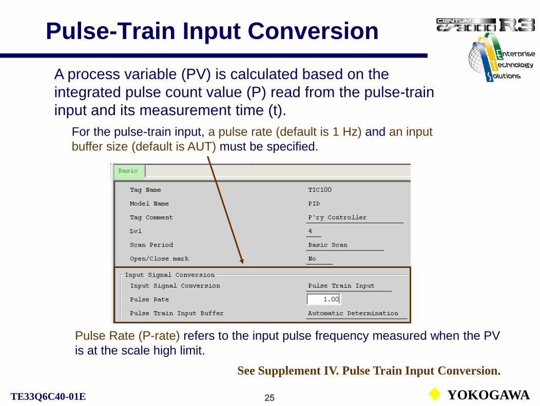
25 YOKOGAWATE33Q6C40-01E
Pulse-Train Input Conversion
Pulse Rate (P-rate) refers to the input pulse frequency measured when the PV is at the scale high limit.
See Supplement IV. Pulse Train Input Conversion.
A process variable (PV) is calculated based on the integrated pulse count value (P) read from the pulse-train input and its measurement time (t).
For the pulse-train input, a pulse rate (default is 1 Hz) and an input buffer size (default is AUT) must be specified.

26 YOKOGAWATE33Q6C40-01E
Communication input conversion performs [Data conversion]and [High/low-limit check] for the input data read from the communication module.
Data conversion:With the communication input, the raw input data read from the input terminal may be in the specific format. The data need to be converted into process variable (PV) with the engineering unit.
M=GAIN·N+BIASM: PVN: Communication inputGAIN: Conversion gain
(default is 1.000)BIAS: Conversion bias
(default is 0.000)
High/low-limit check:In order to induce the input open alarm status in the function block, the high/low-limit check is performed.
Communication Input Conversion

27 YOKOGAWATE33Q6C40-01E
Digital FilterThe digital filter is the function to reduce the noises from the process input signal by means of the first-order lag filter. Three coefficients are provided: Coefficient 1, 2 and 3.
α= 0.5(default setting)
Yn=(1-α)·X+ α·Yn-1 Yn = Current filtering dataYn-1 = Previous filtering dataX = Input dataα = Filter coefficient
Filter coefficient (α) and Time constant (T*)
*T: Unit is second and scan period is 1 second.
00.50.750.875
1
0137∞
When IN terminal is connected to I/O module, coefficient 1 is used.
Coefficient 1Coefficient 2Coefficient 3

28 YOKOGAWATE33Q6C40-01E
IntegrationIntegration refers to the function in which the input signal or the value after the input processing is integrated.
• The integration performs integration processing for the calculated value before the digital filtering. • In the calibration mode (CAL), the PV value is integrated. • The time scale is selected from second, minute, hour or day.• The maximum number of totalized digits is 8. When the totalized digits exceed 8, the totalized values are reset to zero and integration continues.
For the integration, the low-input cut value can be specified.

29 YOKOGAWATE33Q6C40-01E
PV/FV/CPV Overshoot
The PV overshoot refers to the function block in which the process variable (PV) is coincided with the scale high-limit (SH) or the scale low-limit (SL) when the data status is invalid (BAD).(PV/CPV overshoot functions when the I/O connection method is the process connection. FV overshoot functions only for the motor control function blocks.)
Reason for invalidity (BAD) and overshoot value.
The default setting is “Holding PV”.“Overshoot PV” is also selectable.
With “Holding PV,” when the data status of process variable (PV) becomes invalid, the last good process variable is held.
See IM33S01B30-01E PART-C Function Block Common, C5 Alarm Processing - FCS.

30 YOKOGAWATE33Q6C40-01E
Calibration
The calibration is the function in which the emulated signal for a process variable (PV) or a calculated output value (CPV) in the function block can be set manually by the operation and monitoring functions for maintenance or testing.
• The color of PV bar display changes to cyan.• The process variable can be set manually.• Integration continues with the process variable (PV).• The alarm check for the process variable (PV) is bypassed.• Block mod changes to manual (MAN).
Calibration setting button

31 YOKOGAWATE33Q6C40-01E
Control Computation Processing
CS1000/3000 Engineering Course Textbook
PART-B 4Control Computation Processing

32 YOKOGAWATE33Q6C40-01E
Control Computation Processing
PID Control Computation
PID / PI-D / I-PD
PI / IVelocity / Positional
Algorithms Output actions
PV
SVMVΔMV
The PID control computation in the PID control function block calculates a manipulated output change (ΔMV) with the specified PID control algorithm. And then either velocity form or positional form output action converts the ΔMV to MV.
The figure below shows a block diagram of PID control computation:

33 YOKOGAWATE33Q6C40-01E
Output Processing
CS1000/3000 Engineering Course Textbook
PART-B 5Output Processing

34 YOKOGAWATE33Q6C40-01E
Output ProcessingOutput processing refers to the processing that is executed to the values obtained from the control computation before output it.
Output limiter ΔMV limiter
Control computation MV
TRK
Output module
MAN/TRK
RMV
MH ML
Preset MV
MVrb Output conversion
MAN
TRKROUT
+
++
Aux. output No conversion
TIN SUB OUT
AUT/CAS/RCAS/PRD AUT/CAS/RCAS/ROUT/PRD
-

35 YOKOGAWATE33Q6C40-01E
Output Processing
The output processing common to the regulatory control blocks:
• Output limiter• Output velocity limiter• Output clamp• Preset manipulated output• Output tracking• Output range tracking• Manipulated output index• Output conversion (no conversion, pulse width output conversion, communication output conversion and so on)
See IM33S01B30-01E PART-C Function Block Common, C4 Output Processing.

36 YOKOGAWATE33Q6C40-01E
Output Limiter
The output limiter limits the manipulated output (MV) within the manipulated output high-limit (MH) and low-limit (ML) values in AUT mode.
High/low limit expansion function
When the mode is transferred from MAN to AUT mode, if the manipulated output has exceeded the high/low limit values, the high/low limit values are temporarily expanded to avoid abrupt change in the manipulated output (MV).

37 YOKOGAWATE33Q6C40-01E
Output Velocity Limiter
It is a function to limit the amount of change between the previous and the current manipulated outputs, so as to avoid the abrupt changes in MV.
• The output velocity limiter can be bypassed in MAN mode.• In MAN mode the manipulated output values are displayed intact on the operation and monitoring windows.• The limiter does not function in a 2-position and a 3-position ON/OFF controller.
The output velocity limiter is ineffective in the default setting (100%).

38 YOKOGAWATE33Q6C40-01E
Output Clamp
Output clamp prevents the manipulated output value (MV) from exceeding or falling below the current value.
The high limit clamp (CLP+) or the low-limit clamp (CLP-) of MV data status is initiated on one of the following conditions:
C is indicated in the MV pointer.
• The output value is limited by the output limiter.• The data status of the cascade-connected destination is either CLP+ or CLP-.
C
CLP+ and CLP- are the data status.
C
C

39 YOKOGAWATE33Q6C40-01E
Preset Manipulated Output
The preset manipulated output forces a block mode to MAN and output a preset value as the manipulated output MV through an external command.
The command to output the preset value is generated by switching the preset MV switch (PSW) from 0 to 1, 2 or 3.
• PSW=0: Preset manipulated output is not effective.• PSW=1: MV=MSL (Low limit value of MV)• PSW=2: MV=MSH (High limit value of MV)• PSW=3: MV=PMV (Preset MV output value)
The preset MV switch (PSW) value will be automatically reset to 0 when the preset manipulated output function is activated to set the manipulated output (MV) at a preset value.The preset manipulated output value (PMV) is a value set as a tuning parameter from the operation and monitoring function, or from the General-Purpose Calculation Blocks.

40 YOKOGAWATE33Q6C40-01E
Output Tracking
The output tracking is the function that forces the output value to match the value of the output destination or the value of the tracking input value.
TIC101
PID
OUT
FIC101
PID
SET
Output tracking [In TRK (tracking) mode and IMAN (initialization manual) mode]
Terminal connection
MV

41 YOKOGAWATE33Q6C40-01E
Output Range TrackingThe output range tracking is the function that forces the scale high/low-limit of the MV to match those of the output destination, and the values of data items related to the MV are recalculated whenever the scale high/low-limit changes.
Output range tracking (MSH and MSL in the upper stream will track SH and SL in the downstream.)
PID
MSHMSLOUT
Terminal connection
PID
SHSL
SET
The output range tracking is the default setting (Automatic). When (Self) is specified, output range changes to 0 to 100% for free setting.

42 YOKOGAWATE33Q6C40-01E
Manipulated Output Index
The manipulated output indexes show the permissible range of the manual MV at normal operation. The manual output index is only available for regulatory control blocks.
Permissible MV range
(OPHI, OPLO)
The default setting for the indexes is Yes. The values can be set on the tuning window.

43 YOKOGAWATE33Q6C40-01E
Output Signal ConversionThe output signal conversion converts the result of control calculation to an output format for the output modules or other function blocks. The output signal conversion may be used for the processes common to the regulatory control blocks and the calculation blocks, and for the processes for the specific function blocks.
Output signal conversion processes common to function blocks and calculation blocks:
• No conversion• Pulse width output conversion (only for regulatory control blocks)• Communication output conversion
Output signal conversion processes for specific function blocks:
• Motor control block output• 2 or 3-position ON/OFF controller output• Time proportional ON/OFF controller output• Flow/mass totalizing batch set block output• Pulse count block output
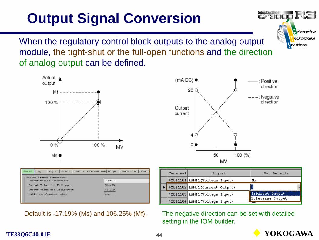
44 YOKOGAWATE33Q6C40-01E
Output Signal ConversionWhen the regulatory control block outputs to the analog output module, the tight-shut or the full-open functions and the direction of analog output can be defined.
The negative direction can be set with detailed setting in the IOM builder.
Default is -17.19% (Ms) and 106.25% (Mf).

45 YOKOGAWATE33Q6C40-01E
Alarm Processing - FCS
CS1000/3000 Engineering Course Textbook
PART-B 6Alarm Processing - FCS

46 YOKOGAWATE33Q6C40-01E
Alarm Processing - FCS
Alarm detection function
Alarm detection setting
Alarm inhibition(AOF)
Alarm setpoint values
Alarm acknowledgement state
Alarm status
Alarm message
Process data
Function blocks
Re-warning alarm
Acknowledgement operation
The function that detects abnormality of the process from PV, MV and other values.
The function that summarizes the results of the alarm detection function and notifies the operation and monitoring functions as a message.
Alarm notification
function

47 YOKOGAWATE33Q6C40-01E
Alarm Detection Function
The following alarm detections are performed:
• Input open alarm check• Input error alarm check• Input high-high/low-low limit alarm check• Input high/low limit alarm check• Input velocity alarm check• Deviation alarm check• Output open alarm check• Output high/low-limit alarm check• Connection failure alarm check
Data item
HH, LLPH, PLVLDV
MH, ML
Alarm status*IOP, IOP-IOP, IOP-HH, LLHI, LOVEL+, VEL-DV+, DV-OOPMHI, MLOCNF
* Colors of alarm status are of default.
See IM33S01B30-01E PART-C Function Block Common, C5 Alarm Processing - FCS.See also Supplement V. Block Mode and VI. Block Status, Alarm Status, Data Status.

48 YOKOGAWATE33Q6C40-01E
Input Open Alarm CheckThe input open alarm check generates the high/low limit input open alarm (IOP, IOP-) when the input value is out of the range of the high/low limit input open detection setpoint.The Input open alarm check is performed by the input module. The function blocks that are connected directly to the input module receives the check results from the input module as a data status, and the high and low limit input open alarm is activated or recovered.
Operations at IOP generation:• Stop the input processing.• Hold the input value (Holding PV) before the alarm occurrence (when “Overshoot PV” is not defined).• In the regulatory control blocks, MAN fall back operation is performed and the block mode changes to MAN.
The setting of the input open alarm check type can be defined in the “input open alarm” on the Function Block Detail Builder.The high and low limit input open detection setpoint values can be defined in the IOM Builder Detail Setting.The default values of input open detection setpoint:
IOP = 106.3 %, -IOP = -6.3 %

49 YOKOGAWATE33Q6C40-01E
Input Error Alarm Check
The input error alarm check determines whether the data status of the input value is invalid (BAD). When the data is invalid (BAD), the high-limit input open alarm (IOP) is activated*.
The possible causes of the invalid (BAD) data status of the input value are listed below:• Input open detected• I/O module failure• Block mode of the block for data reference is disabled (O/S)• Data status of the data for data reference is invalid (BAD)• Data status of the input value fails to communicate (NCOM)
* However, when the cause of the invalidity (BAD) data status is low-limit input open, the low-limit input open alarm (IOP-) is activated and the high-limit input open alarm (IOP) is not activated.

50 YOKOGAWATE33Q6C40-01E
HH, PH, PL and LL Alarm Check
The input high-high limit, high limit, low limit and low-low limit alarm check may generate an alarm to indicate that the input signal is in high-high, high, low and low-low alarming status (HH, HI, LO, LL).
Hysteresis (HYS):Engineering unit data within the range of 0 to PV scale span, or percentage data for the PV scale span. When specifying percentage data, add % after the numeric value. The default is 2.0 %.

51 YOKOGAWATE33Q6C40-01E
Velocity Alarm Check
The input velocity alarm check may generate an alarm to indicate that the velocity in positive direction (VEL+) or velocity in negative direction (VEL-) is in alarming status.
• Hysteresis (HYS): The default is 2.0 %.• Number of samplings (N): 1 to 12 points. The default setting is 1 point• Sampling interval (Tp): 1 to 10,000. Unit is scan interval. The default setting is 1

52 YOKOGAWATE33Q6C40-01E
Deviation Alarm Check
The deviation alarm check may generate an alarm to indicate that the deviation (DV=PV-SV) in positive direction (DV+) or the deviation in negative direction (DV-) is in alarming status.
To prevent occurrence of the undesired alarm caused by abrupt set value change or setvalue ramp, the velocity change speed (derivative value) of the setpoint value (SV) is used as the deviation alarm setpoint value correction factor (r) to compensate the deviation alarm setpoint value (DL).
• Hysteresis (HYS): The default is 1.0 %.

53 YOKOGAWATE33Q6C40-01E
Output Open Alarm Check
The output open alarm check may generate an alarm to indicate that the output is open (OOP).The output open alarm check is performed by the I/O module. The function block receives the check results from the I/O module as a data status (OOP) and processes the activation or the restoration of the output open alarm. The output open alarm is activated only in the function block that is directly connected to the I/O module. The alarm will not be activated at function blocks that sends output through data connections to other function blocks.When I/O modules are duplicated, an output open alarm is activated if both I/O modules are failed.
Operations at OOP generation:• For the regulatory control blocks that have MAN fallback functions, the MAN fallback action is initiated and the block mode is changed to manual (MAN) mode.• The manipulated output value (MV) is frozen, and the current value is kept as manipulated output values (MV).

54 YOKOGAWATE33Q6C40-01E
MH and ML Alarm Check
The output high and low limit alarm check is a function that determines whether the manipulated output value (MV) exceeds the range of the manipulated output variable high-limit/ low-limit setpoint (MH, ML) for the output limiter.
When it is determined that the manipulated output value (MV) exceeds the manipulated output variable high limit setpoint (MH), an output high limit alarm (MHI) is activated. Similarly, when it is lower than the manipulated variable low limit setpoint (ML), an output low limit alarm (MLO) is activated.
• Hysteresis (HYS): The default is 2.0 %.

55 YOKOGAWATE33Q6C40-01E
Alarm Messages
• Process alarm messages:The process alarm messages are transmitted when abnormality in the process variables (PV) or manipulated output values (MV) is detected by the alarm detection function of the function block, and when the abnormality returns to normal.
• System alarm messages:The system alarm messages are the messages transmitted to the operation and monitoring functions from the FCS about abnormalities occurred in the system of the FCS.
• Input module abnormality• Output module abnormality• Abnormality in the user defined calculations • Abnormality in the sequential control blocks at one-shot initiation

56 YOKOGAWATE33Q6C40-01E
Process Alarm MessageThe occurrence of a process alarm message is shown below:

57 YOKOGAWATE33Q6C40-01E
Process Alarm Notification FlowSystem message window
Process alarm
occurrence
✓
Graphic window
Process alarm window
Related window
Alarm acknowledgement
PrintoutBuzzer soundsSave in file
Navigator window

58 YOKOGAWATE33Q6C40-01E
System Alarm MessageThe occurrence of a system alarm message is shown below:

59 YOKOGAWATE33Q6C40-01E
Deactivate Alarm Detection and Alarm Off
• Deactivate alarm detection function:For each alarm detection function of the process alarms, the alarm detection status can be changed by setting the detection function to “enabled” or “disabled”.
• Alarm OFF (inhibition) function (AOF)The process alarm message operation can be temporarily suppressed leaving the alarm detection function operating.
AOF setting button

60 YOKOGAWATE33Q6C40-01E
Alarm Related BuildersThree alarm related builders are provided in COMMON folder:
Alarm priority: For the 5 alarm priorities, output operations and alarm actions are specified.
Alarm status character string: Up to 32 alarm status labels for each function block are defined.
Alarm processing table: Up to 16 alarm processing levels can be defined.
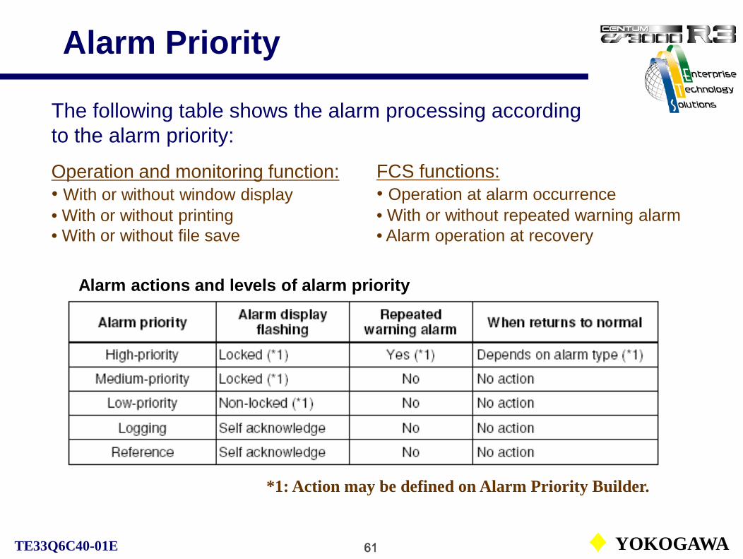
61 YOKOGAWATE33Q6C40-01E
Alarm Priority
The following table shows the alarm processing according to the alarm priority:
Operation and monitoring function:• With or without window display• With or without printing• With or without file save
FCS functions:• Operation at alarm occurrence• With or without repeated warning alarm• Alarm operation at recovery
*1: Action may be defined on Alarm Priority Builder.
Alarm actions and levels of alarm priority

62 YOKOGAWATE33Q6C40-01E
Alarm Processing Level
With the alarm processing level, the alarm priority level can be specified for each function block or element.There are 16 alarm processing levels*. The alarm priority and alarm colors of all alarms occurred in a function block or an element are defined for each processing level.
* The alarm processing level can be designated in the Function Block Overview Builder and the Function Block Detail Builder.
Tag Mark, Alarm Priority, and Security Level (Default)
The definitions level 1 through level 4 have been defined by the system. Level 5 through level 16 are for user definitions.
Any combination of a tag mark, an alarm priority, and a function block security level can be designated.

63 YOKOGAWATE33Q6C40-01E
Alarm Actions
High and medium priority alarm.
Low priority alarm.
Logging and reference alarm.
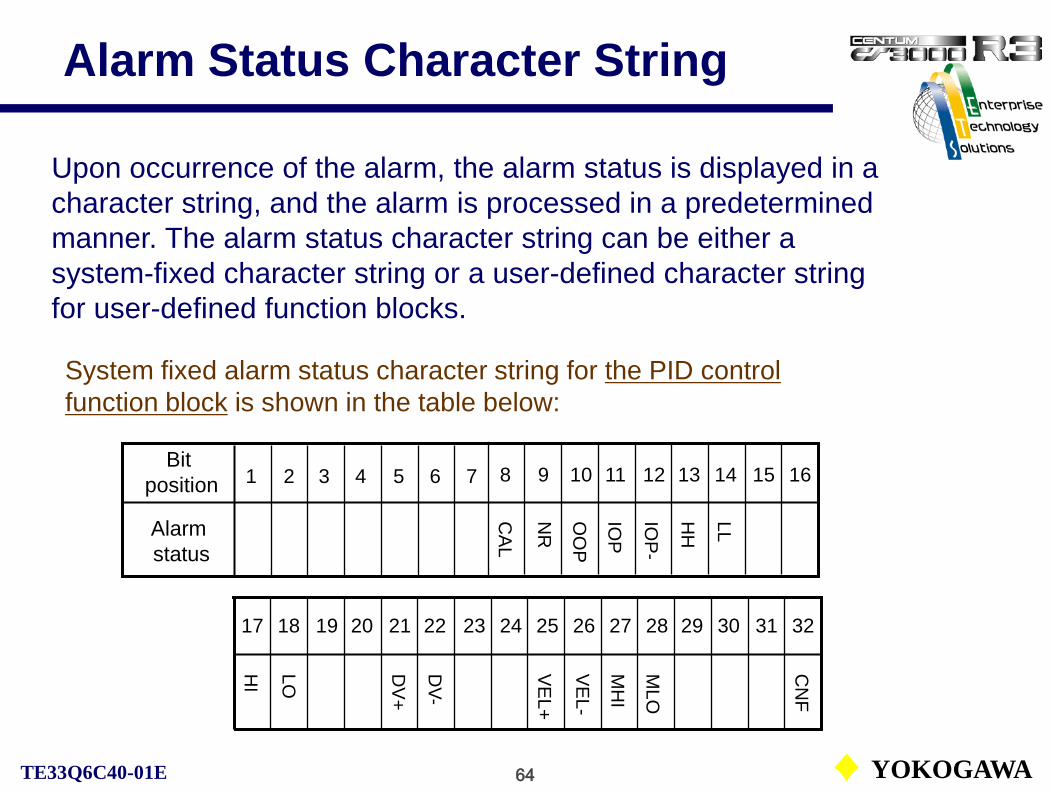
64 YOKOGAWATE33Q6C40-01E
Alarm Status Character String
Upon occurrence of the alarm, the alarm status is displayed in a character string, and the alarm is processed in a predetermined manner. The alarm status character string can be either a system-fixed character string or a user-defined character string for user-defined function blocks.
System fixed alarm status character string for the PID control function block is shown in the table below:
17 18 19 20 21 22 23 24 25 26 27 28 29 30 31 32
CA
L
NR
OO
P
IOP
IOP
-
HH
LL
HI
LO DV
+
DV-
VE
L+
VE
L-
MH
I
MLO
CN
F
Bit position
Alarm status
1 2 3 4 5 6 7 8 9 10 11 12 13 14 15 16

65 YOKOGAWATE33Q6C40-01E
Alarm Processing TableAlarm status bit positions 1 to 6 are not displayed in a window because they are system-fixed. Alarm processing level Nos. 1 to 4 are also system-fixed. The user can designate the color and the priority for alarm processing level Nos. 5 to 16 for alarm status bit positions 7 to 32.
Alarm status bit position Alarm processing level number
System-fixed User-defined

66 YOKOGAWATE33Q6C40-01E
System-fixed Alarm Status Change (1)
The system-fixed alarm status character string itself cannot be changed, but its color and priority can be changed.
Bit position assignment of the PID controller block is shown in the previous slide. If we want to designate the “HH” and “LL” alarms in a PID function block to be processed as a high-priority alarm, and displayed in magenta, while “HI” and “LO” alarms to be processed as a medium-priority alarm, and displayed in orange, do the following:
1. In the Alarm Processing Table Builder, designate [M: Magenta] for [Color (5)], and [1: High-priority Alarm] for [Priority (5)] for bit positions 13 (HH) and 14 (LL) on the alarm processing level No.5. Next, designate [OR: Orange] for [Color (5)], and [2: Medium-priority Alarm] for [Priority (5)]. for bit positions 17 (HI) and 18 (LO).
(The alarm priority after bit position 19 should be the medium priority alarm as the higher priority to be designated in ascending order of the bit position.)

67 YOKOGAWATE33Q6C40-01E
System-fixed Alarm Status Change (2)
Designate magenta
Medium priority alarm
2. Select the [Alarm] tab in the Function Block Detail Builder, and then select [5: User-defined Alarm Process (5)] at [Alarm Processing Level].
Designation in the Alarm Processing Table Builder.
Designate orange
High priority alarm

68 YOKOGAWATE33Q6C40-01E
Block Mode and Status
CS1000/3000 Engineering Course Textbook
PART-B 7Block Mode and Status

69 YOKOGAWATE33Q6C40-01E
Block Mode and Status
Block mode and status are the information that represent the conditions of the function blocks.
• Block mode• Block status
• Alarm status
• Data status
Represent the operating state of the function blocks.
Represents the alarm state of the process.
Represents the quality of the process data.
See IM33S01B30-01E PART-C Function Block Common, C6 Block Mode and Status.See also Supplement VI. Block Status, Alarm Status, Data Status.

70 YOKOGAWATE33Q6C40-01E
Block Mode
The block mode is the information that represents the control state and the output state of a function block. The different type of function blocks have the different block modes. There are 9 basic block modes and several compound block modes.
Basic block mode:O/S, IMAN, TRK, MAN, AUT, CAS, PRD, RCAS, ROUT
Compound block mode:The state where multiple basic block modes are established at a time.e.g. AUT – IMAN
See Supplement V. Block Mode

71 YOKOGAWATE33Q6C40-01E
Basic Block Modes
O/S: (Out of Service) All functions of the function block are currently stopped.IMAN: (Initialization MANual) Calculation processing and output processing are currently stopped.TRK: (TRacKing) Calculation processing is currently stopped and the specified value is forced to be output.MAN: (MANual) Calculation processing is currently stopped and the manipulated output value, which is set manually, is output.AUT: (AUTomatic) Calculation processing is being executed and the calculation result is output.CAS: (CAScade) Calculation processing is being executed, the set value CSV is from the cascadeconnected upstream block, and the calculation result referred to this CSV is output.PRD: (PRimary Direct) Calculation processing is currently stopped, the set value CSV is from the cascade connected upstream block, this CSV is output directly.RCAS: (Remote CAScade) An control and calculation processing is being executed using the remote setpoint value (RSV) which is set remotely from a supervisory system computer, and the calculation results is output.ROUT: (Remote OUTput) Calculation processing is currently stopped, and the remote manipulated output value (RMV) which is set remotely from a supervisory system computer is output directly.

72 YOKOGAWATE33Q6C40-01E
Tracking Mode (TRK)
The tracking mode is used to switch the MV from one function block to another function block balance-less bump-less.When the tracking switch (TSW) is ON (1), the data for the TIN terminal is output. When TSW is OFF (0), PID computation result is the output.
SV
FIC
Pressure
PIC1
1PV
PVSV
Flow
Switch
0 – 100 Nm3/min
Vane control drive
TIN data
0 – 100 kPa
Blower
TSW input
1
0

73 YOKOGAWATE33Q6C40-01E
Primary Direct Mode (PRD)
When the block mode is set to PRD, calculation processing is currently stopped. The set value CSV is from the cascade connected upstream block is output to the control valve after output processing.
MV1 MV2P’ry Controller
SV2
S’ry Controller
PRD PRD
[AUT]
[PRD]
OutputProcessing
ControlComputation
SV1 CAS CAS

74 YOKOGAWATE33Q6C40-01E
Basic Block Modes Relationship
O/S
IMAN
TRK
MAN, AUT, CAS, PRD
RCAS, ROUT
Complementary relationship
Exclusive relationship
Priority level
High
Low
4
3
2
1
0
75 YOKOGAWATE33Q6C40-01E
Block Mode Change Interlock
Block mode change interlock condition:
When the status of the interlock switch connected to the terminal (INT) becomes ON, the block mode change interlock establishes, then succeeded by the following actions:
• The MAN fallback condition establishes, and the block mode changes to manual (MAN).
• Any mode change command to put the function block into an automatic operation status (AUT, CAS, PRD, RCAS or ROUT mode) is invalidated.

76 YOKOGAWATE33Q6C40-01E
Status
Block status:A block status is the information that represents the operating state of a function block. Some function blocks do not have any block status.e.g. PALM, CTUP status of TM block
Alarm status:An alarm status is the information that represents the alarm state of a process which was detected by the function block.e.g. HI, LO status of PID block
Data status:A data status is the information that represents the quality of data. The status passes from a function block to another by I/O operation. The data status if observed when various exceptional events occurred due to abnormality in the process input or calculation.e.g. BAD, IOP status of data
See Supplement VI. Block Status, Alarm Status, Data Status.

77 YOKOGAWATE33Q6C40-01E
Processing Timing
CS1000/3000 Engineering Course Textbook
PART-B 8Processing Timing

78 YOKOGAWATE33Q6C40-01E
Processing Timing
An individual function block executes an input, a calculation or an output processing according to the processing timing.There are four types of the processing timing:
• Periodic execution:Executed repeatedly with preset period.
• One-shot execution:Executed only once when invoked from another function block.
• Initial execution / Restart execution:Executed when FCS executes start operation.
• Initial execution:Executed when FCS executes cold start operation.
See IM33S01B30-01E PART-C Function Block Common, C7 Processing Timing.
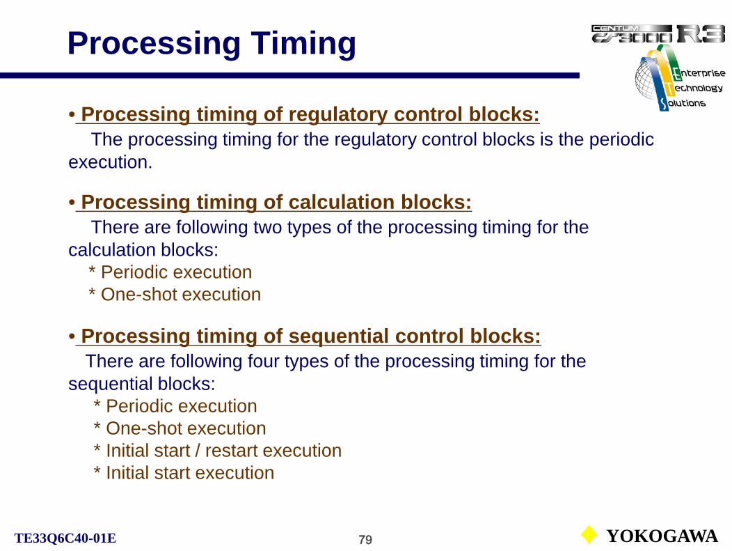
79 YOKOGAWATE33Q6C40-01E
Processing Timing
• Processing timing of regulatory control blocks:The processing timing for the regulatory control blocks is the periodic
execution.
• Processing timing of calculation blocks:There are following two types of the processing timing for the
calculation blocks:* Periodic execution* One-shot execution
• Processing timing of sequential control blocks:There are following four types of the processing timing for the
sequential blocks:* Periodic execution* One-shot execution* Initial start / restart execution* Initial start execution

80 YOKOGAWATE33Q6C40-01E
Processing TimingThe processing timing that activates the individual function blocks and control drawings are determined by the following factors in the periodic execution of the regulatory control blocks: Scan period:Basic scan, medium-speed scan, high-speed scan.Execution order of processing:Control drawings are executed in order of the drawing number. Function blocks in one control drawing are executed ion order of the function block number.Process I/O processing timing:The processing timing varies by the analog I/O and status I/O.Control period of regulatory control block:A regulatory control block has a control period besides the scan period.
Medium and high-speed scan period are defined on the FCS property window.
(Some FCSs have no medium-scan period.)

81 YOKOGAWATE33Q6C40-01E
Scan Periods
Scan period determines a period for the periodic execution of the function block. There are three types of scan periods: basic scan, medium-speed scan and high-speed scan.
● Basic ScanThe basic scan is a standard scan period which is common to function blocks.The basic scan period is fixed to 1 second. This cannot be changed.● Medium-Speed Scan (LFCS/KFCS)The medium-speed scan is a scan period suited for the process control that requiresquicker response than what can be achieved with the basic scan setting. Setting value of the medium-speed scan can be selected by each FCS according to its use.Setting value of the medium-speed scan can be changed on System View:• Medium-speed scan period: Select “200 ms” or “500 ms.” The default is “500 ms.”● High-Speed ScanThe high-speed scan is a scan period suited for the process control that requires high-speed response. Setting value of the high-speed scan can be selected by each FCS according to its use.Setting value of the high-speed scan can be changed on System View:• High-speed scan period: Select “50 ms,” “100 ms,” “200 ms” or “500 ms.” The default is “200 ms.”

82 YOKOGAWATE33Q6C40-01E
Execution Order
1st priority2nd priority3rd priority
The groups of high-speed scan function blocks in three drawings are indicated as A, B and C. Similarly, the groups of medium-speed scan function blocks, A’, B’ and C’; and the basic scan function blocks, a, b and c.

83 YOKOGAWATE33Q6C40-01E
Control PeriodAmong the regulatory control blocks, the controller block has a control period besides the processing period. The control period is the period that the controller block executes control computation and output processing during the automatic operation. The control period is always an integer multiple of the scan period of 1 second. Input and alarm processing are performed at each scan period.
In ‘Automatic determination’, the control period is defined in accordance with the integral time.
High- Medium- Speed Scan

1 YOKOGAWATE33Q6C40-01E
Regulatory Control Functions
CS1000/3000 Engineering Course Textbook
PART-C
Regulatory Control Functions

2 YOKOGAWATE33Q6C40-01E
Regulatory Control Functions
C1. Regulatory Control PositioningC2. Regulatory Control Block StructureC3. Types of Regulatory Control BlocksC4. Control Computation of Control Block
Reference: IM33S01B30-01EPART-D Function Block Details, D1 Regulatory Control
CS1000/3000 Engineering Course Textbook
PART-C Regulatory Control Functions

3 YOKOGAWATE33Q6C40-01E
Regulatory Control Positioning
CS1000/3000 Engineering Course Textbook
PART-C 1Regulatory Control Positioning

4 YOKOGAWATE33Q6C40-01E
Regulatory Control PositioningThe regulatory control block performs control computation processing using analog process variables and so on for the process monitoring and control.
FCS
Basic control Software I/O
I/O interfaces

5 YOKOGAWATE33Q6C40-01E
Regulatory Control Block Structure
CS1000/3000 Engineering Course Textbook
PART-C 2Regulatory Control Block Structure

6 YOKOGAWATE33Q6C40-01E
Regulatory Control Block StructureThe structure of regulatory control function block PID:
OUT
SUB
AUTMAN
SET
CAS
IN
INTTSITINRL2RL1BIN
RCAS
(VN) (RLV1) (RLV2) (TSW)
(PV, ΔPV, MV, ΔMV)
RAW
CSV
RSV
PV
SV
RMV
MV
Detects an abnormalityin PV, MV and notifiesthe operation and monitoring functions.
Reads MV and outputs the result of output processing to the output terminal.
Reading a raw data from the input terminal, performs input processing to output PV.
Input processing
Control computation processing
Alarm processing
Output processing
CASAUT
MAN
ROUT
Reading PV and SV, performs control computation processing to output MV.

7 YOKOGAWATE33Q6C40-01E
Data Items and Terminals
The following list shows the data items and the terminals of the PID control function block:
*1
*1
*2
*2
*3*3
*3
*4
*1: Either input or output compensation is possible.*2: Used for the reset limit function.*3: Used for the output tracking function.*4: Interlock the block mode transfer.*5: Remote value means the value from another computer.
*5
*5

8 YOKOGAWATE33Q6C40-01E
Types of Regulatory Control Block
CS1000/3000 Engineering Course Textbook
PART-C 3Types of Regulatory Control Blocks

9 YOKOGAWATE33Q6C40-01E
Types of Regulatory Control Block
The regulatory control blocks vary by the types of data handled and control computation processing functions provided.
• Input indicator blocks• Controller blocks• Manual loader blocks• Signal setter blocks• Signal limiter blocks• Signal selector blocks• Signal distributor blocks• Pulse count block• Alarm block• YS blocks
See Supplement VII. Regulatory Control Function Blocks.

10 YOKOGAWATE33Q6C40-01E
Controller Blocks
The table below shows nine controller blocks available:
PID controller block explained in the textbook.
See Supplement X. PI Control Function Block.
11 YOKOGAWATE33Q6C40-01E
Control Computation
CS1000/3000 Engineering Course Textbook
PART-C 4Control Computation of Control Block

12 YOKOGAWATE33Q6C40-01E
PID Control Computation
PID Control Computation
PID / PI-D / I-PD
PI / IVelocity / Positional
PV
SVMV
The PID control computation in the PID control function block calculates a manipulated output change (ΔMV) with the specified PID control algorithm. And then either velocity form or positional form output action converts the ΔMV to MV.
The figure below shows a block diagram of PID control computation:
Algorithms Output actions
ΔMV
See IM33S01B30-01E PART-D Function Block Details, D1.5 PID Controller Block (PID).

13 YOKOGAWATE33Q6C40-01E
PID Control Algorithms (1)The PID control computation is the core of the PID control computation processing, calculating a manipulated output change (ΔMV) by using the PID control algorithms. The PID control is the most widely used, it combines three types of actions: proportional, integral and derivative.
The figure below shows a block diagram of PID control computation:
Control action(P) bypass
Control action(D) bypass
(DV)
(PV)
(PV)

14 YOKOGAWATE33Q6C40-01E
PID Control Algorithms (2)
There are five control algorithms to perform PID computation:
Basic type PID control (PID): A quick response for the SV change can be expected. PV proportional and derivative type PID control (I-PD): SV may be changed not
considering bump. PV derivative type PID control (PI-D): Relatively good response for the SV change
can be expected.

15 YOKOGAWATE33Q6C40-01E
Control Action Bypass
The PID Controller Block can perform the following two types of control action by bypassing proportional and/or derivative actions among the proportional, integral and derivative actions:
To set the control action bypass, specify “0” to the set parameter P or D, as shown in the table above. The proportional gain (Kp) is fixed to “1” when only integral action is required.
Control action bypass:
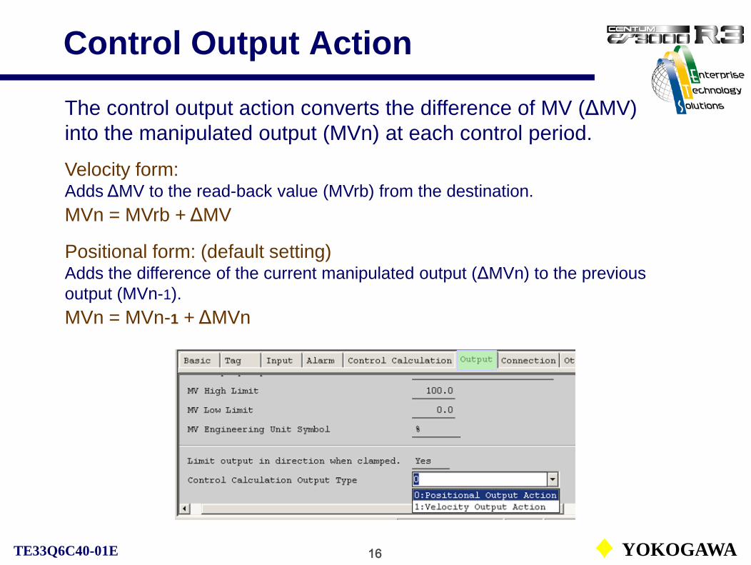
16 YOKOGAWATE33Q6C40-01E
Control Output Action
The control output action converts the difference of MV (ΔMV) into the manipulated output (MVn) at each control period.
Velocity form:Adds ΔMV to the read-back value (MVrb) from the destination. MVn = MVrb + ΔMV
Positional form: (default setting)Adds the difference of the current manipulated output (ΔMVn) to the previous output (MVn-1).MVn = MVn-1 + ΔMVn
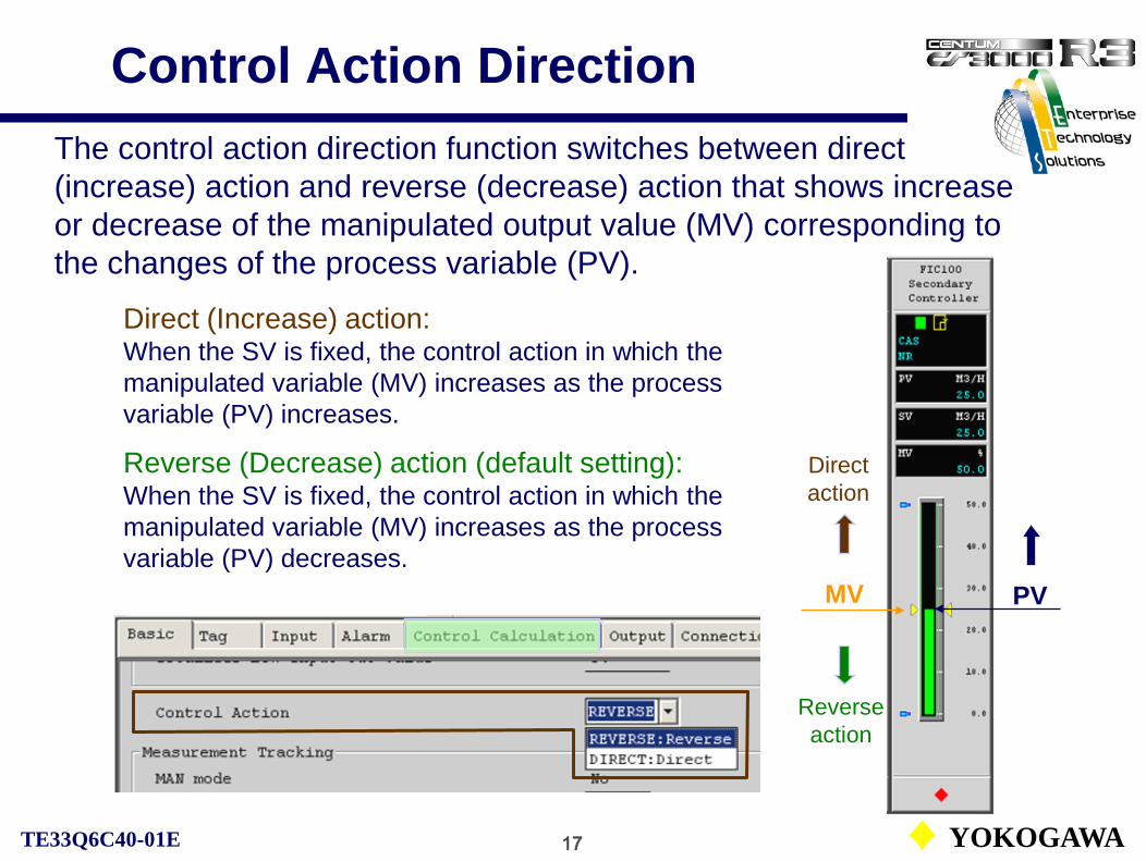
17 YOKOGAWATE33Q6C40-01E
Control Action Direction The control action direction function switches between direct (increase) action and reverse (decrease) action that shows increase or decrease of the manipulated output value (MV) corresponding to the changes of the process variable (PV).
PV
Direct action
Reverse action
MV
Direct (Increase) action:When the SV is fixed, the control action in which the manipulated variable (MV) increases as the process variable (PV) increases.
Reverse (Decrease) action (default setting):When the SV is fixed, the control action in which the manipulated variable (MV) increases as the process variable (PV) decreases.

18 YOKOGAWATE33Q6C40-01E
Process Variable TrackingWhen the block mode is switched from manual (MAN) mode to automatic (AUT) mode, if a large deviation exists, the manipulated output (MV) changes the quickly. To prevent this change, the measurement racking function equals the setpoint variable (SV) to the process variable (PV) in the MAN mode.
SVPV
If SV equals PV, MV won’t change as no deviation exists. However, SV is not fixed. Care must be taken when the controller is used with the constant SV.
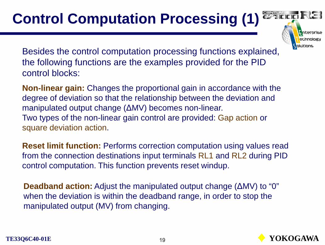
19 YOKOGAWATE33Q6C40-01E
Control Computation Processing (1)
Besides the control computation processing functions explained, the following functions are the examples provided for the PID control blocks: Non-linear gain: Changes the proportional gain in accordance with the degree of deviation so that the relationship between the deviation and manipulated output change (ΔMV) becomes non-linear. Two types of the non-linear gain control are provided: Gap action or square deviation action.
Reset limit function: Performs correction computation using values read from the connection destinations input terminals RL1 and RL2 during PID control computation. This function prevents reset windup.
Deadband action: Adjust the manipulated output change (ΔMV) to “0” when the deviation is within the deadband range, in order to stop the manipulated output (MV) from changing.

20 YOKOGAWATE33Q6C40-01E
Control Computation Processing (2)
I/O compensation: Adds the I/O compensation value (VN) received from outside to the input signal or the control output signal of PID computation when the controller block is in MAN.Either Input compensation (used for the dead-band compensation control) or output compensation (used for the feedforward control) is selectable.
Setpoint value limiter: Limits the setpoint value (SV) within the setpoint High/low limits (SVH, SVL).
Setpoint value pushback: Causes two of the three setpoint values (SV, CSV, RSV) to agree with the remaining one.
See Supplement IX. Control Computation Processing.
Bumpless switching: When the block mode is changed or when the manipulated output (MV) is switched in a downstream block, no bump occurs in the MV.

1 YOKOGAWATE33Q6C40-01E
Operation and Monitoring Functions
CS1000/3000 Engineering Course Textbook
PART-D
Operation and Monitoring Functions

2 YOKOGAWATE33Q6C40-01E
Operation and Monitoring Functions
CS1000/3000 Engineering Course TextbookPART-D Operation and Monitoring Functions
Reference: IM33S01B30-01EPART-E Human Interface Station
D1. Engineering ProceduresD2. Basic Definitions of HISD3. Operation and Monitoring FunctionsD4. Trend Recording FunctionD5. Message ProcessingD6. Function KeysD7. Other Functions

3 YOKOGAWATE33Q6C40-01E
Engineering Procedures
CS1000/3000 Engineering Course Textbook
PART-D 1Engineering Procedures
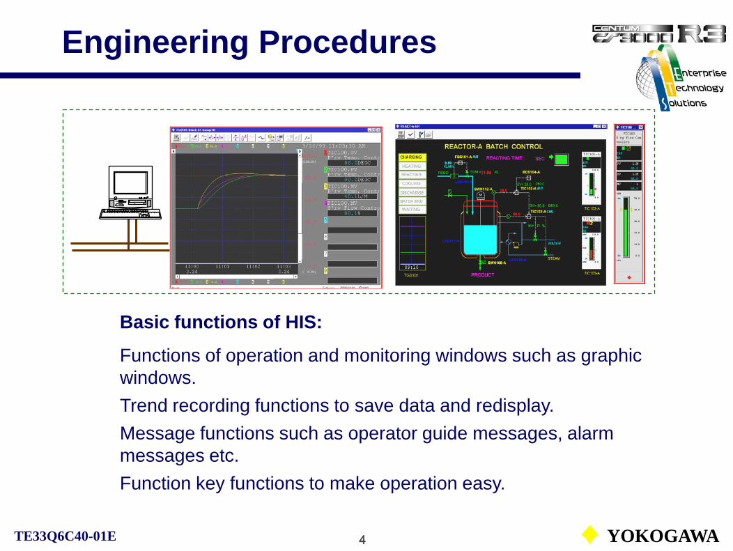
4 YOKOGAWATE33Q6C40-01E
Engineering Procedures
Basic functions of HIS:
Functions of operation and monitoring windows such as graphic windows.Trend recording functions to save data and redisplay.Message functions such as operator guide messages, alarm messages etc.Function key functions to make operation easy.

5 YOKOGAWATE33Q6C40-01E
Engineering Procedures
Define functions necessary for the operation and monitoring.
The functions supporting the operations such as the function key functions may be changed directly by HIS SetUp window.
Details of HIS SetUp window are explained in the fundamental course textbook.
HIS constant definition
Function key definition
Scheduler definition
Trend definition
Sequence message definition
Graphic window definition
Help message definition
Plant hierarchy definition
Panel set definition
: Explained in the course.

6 YOKOGAWATE33Q6C40-01E
Basic Definitions of HIS
CS1000/3000 Engineering Course Textbook
PART-D 2Basic Definitions of HIS

7 YOKOGAWATE33Q6C40-01E
HIS PropertyAt the creation of new HIS, device type, station number, network and so on are to be defined with the property window.
Device type
Station number
Protocol of control network* Use default values. No change is allowed.
Information network protocol. Either the default values or the values for the inter-company LAN are acceptable.

8 YOKOGAWATE33Q6C40-01E
HIS Property
Operation group ID
Buzzer acknowledgment ID
The default values of the buzzer ACK ID and the operation group ID may be used. (All HIS belong to a single group.)
9 YOKOGAWATE33Q6C40-01E
Buzzer ACK ID
The buzzer ACK ID is an ID that allows buzzers on other HIS’s with same buzzer ACK ID to be reset when a the buzzer is acknowledged on one HIS.
Buzzer ACK identifier:• The buzzer ACK ID can be set with up to eight alphanumeric characters.

10 YOKOGAWATE33Q6C40-01E
Operation Group
A number of HIS on the same communication bus are grouped based on the operation policy, and the operation and monitoring can be performed in the unit of the group. This group is referred to as the operation group.
Acknowledgement of operation guide message, panel set call, remote window call and so on.
Group identifier:• Up to 8 alphanumeric characters. The first two characters are for an ID, and the characters from the third are for comment text.• The wild card [*] may be used.

11 YOKOGAWATE33Q6C40-01E
Definition of HIS Constants
Details of HIS can be defined on each item with the OpeconDef file in the CONFIGURATION folder in the HIS folder.
An example of the window to define a switch instrument diagram operation as one of HIS constants.
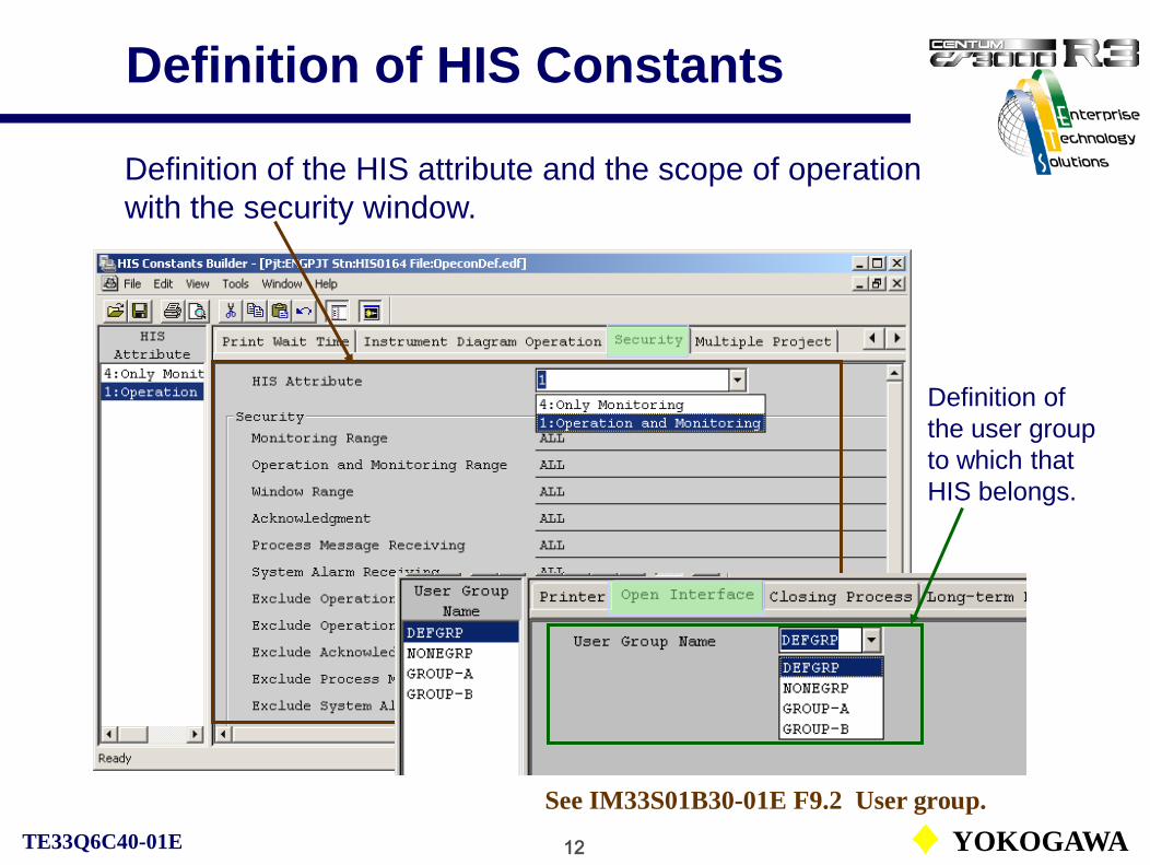
12 YOKOGAWATE33Q6C40-01E
Definition of HIS Constants
Definition of the HIS attribute and the scope of operation with the security window.
Definition of the user group to which that HIS belongs.
See IM33S01B30-01E F9.2 User group.

13 YOKOGAWATE33Q6C40-01E
Definition of HIS ConstantsWindows to define functions related to the data save.
The Long-term Data Save is intended for the long-term storage of trend data.(optional package)
The Closing Process creates closing data for statistical processing, such as average values and total values.

14 YOKOGAWATE33Q6C40-01E
HIS Constants and HIS Setup Message printout, security and so on are defined with the HIS constants definition window. Setup of the printer output, window switching, screen mode and so on are set with HIS Setup window.
See TE33Q4T30-01E Fundamental Course Textbook.
HIS Setup window
System Status
Overview

15 YOKOGAWATE33Q6C40-01E
Operation and Monitoring Functions
CS1000/3000 Engineering Course Textbook
PART-D 3Operation and Monitoring Functions

16 YOKOGAWATE33Q6C40-01E
Operation and Monitoring WindowThe operation and monitoring windows include the built-in system windows and user-defined windows that can define applications and display contents freely at the system generation.Number of user-defined windows: CS3000 = 4000 / HIS, CS1000 = 1000 / HIS
User-defined widows can be created or added with the window creation function in WINDOW folder in HIS.

17 YOKOGAWATE33Q6C40-01E
Window Attributes
Attributes and other functions can be defined for each window.
Definition of window operation and monitoring authority.
A window may be named as desired.
Definition of attributes for graphic, control, overview windows.

18 YOKOGAWATE33Q6C40-01E
Operation and Monitoring Authority
Operation and monitoring authority for windows:
Default setting of operation and monitoring authority.

19 YOKOGAWATE33Q6C40-01E
Trend Recording Function
CS1000/3000 Engineering Course Textbook
PART-D 4Trend Recording Function

20 YOKOGAWATE33Q6C40-01E
Trend Recording Function
The trend recording function periodically gathers process data such as temperature, pressure, flow and so on from an FCS with HIS. The acquired data may be displayed as trend graphs.
Trend data collection
SaveAS
TG01011 FIC100.PV2 TIC200.PV3 LIC300.PV
Trend window / Trend point window
Long-term trend
Closing processing
Trend display
Process data from the FCS within the security scope.
To Report processing / General applications
* Optional
Trend record
Referencing data from other security scope.

21 YOKOGAWATE33Q6C40-01E
Trend Recording Function
Trend groupTG0101
1 FIC100.PV2 TIC200.PV3 LIC300.PV45678
LIC300.PV3 LIC300.PV
The trend recording consists of the three layers of the trend blocks, the trend windows and the trend point windows.Trend blockTrend block 01
TR0001Trend block 02
TR0002Trend block 03
TR0003
Trend block 50TR0050
Trend group 1TG0101
Trend group 2TG0102
Trend group 3TG0103
Trend group 16TG0116
Trend window
Trend point window
Trend window nameTGbbggbb: Block numbergg: Group number
Maximum number trend blocks for CS1000 is 8.
Each trend block can specifies trend type and sampling period.

22 YOKOGAWATE33Q6C40-01E
Structure of Trend
Trend block:A trend block is comprised of 16 units of trend windows.There are 50 trend blocks (CS3000) per HIS. Up to 20 of the 50 trend blocks can be defined as the trend of own station. The remaining 30 trend blocks are defined as the trend of other stations. (8 trend blocks for CS1000 and no trend of other stations)The trend format and sampling period are defined for each trend block.
Trend window:8-pen trend data can be assigned to a trend window. There are 800 trend windows (CS3000) per HIS. (128 windows for CS1000)
Trend point window:One trend pen is displayed in each trend point window. There are 6,400 trend point windows (CS3000) per HIS. (1,024 widows for CS1000)
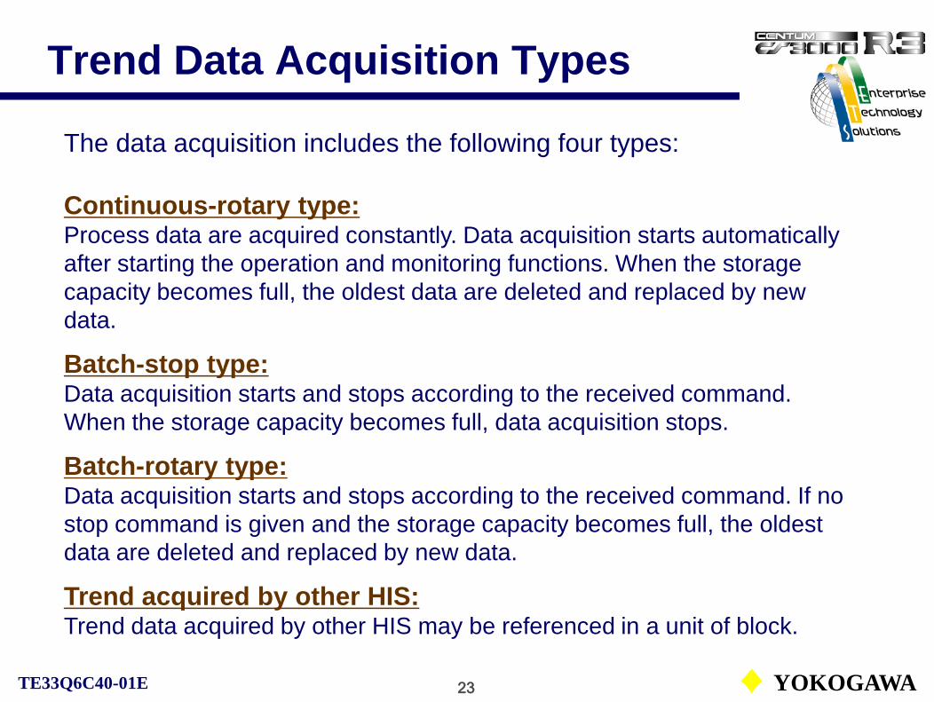
23 YOKOGAWATE33Q6C40-01E
Trend Data Acquisition Types
The data acquisition includes the following four types:
Continuous-rotary type:Process data are acquired constantly. Data acquisition starts automatically after starting the operation and monitoring functions. When the storage capacity becomes full, the oldest data are deleted and replaced by new data.
Batch-stop type:Data acquisition starts and stops according to the received command. When the storage capacity becomes full, data acquisition stops.
Batch-rotary type:Data acquisition starts and stops according to the received command. If no stop command is given and the storage capacity becomes full, the oldest data are deleted and replaced by new data.
Trend acquired by other HIS:Trend data acquired by other HIS may be referenced in a unit of block.

24 YOKOGAWATE33Q6C40-01E
Sampling Period and Recording Span
The sampling period can be selected from 1 second, 10 seconds, 1 minute, 2 minutes, 5 minutes and 10 minutes for each trend block. No more than 2 trend blocks can be specified with the sampling period of 1 second or 10 seconds.
2,880 samples can be acquired per pen. The recording span indicates the time to acquire 2,880 samples for each trend in the specified sampling period.
The table below shows the relationship between the sampling period and the recording span:

25 YOKOGAWATE33Q6C40-01E
Display Data Types
The display data type of each trend gathering pen is defined to display data in the trend window.The data display for the trend gathering pen include the following types:Default: Acquired data are displayed in the default data type in the instrument faceplate showing the function block of the acquisition source.Analog type: Acquired process data are displayed in the data axis range 0 to 100 % of the trend graph.Discrete type: Acquired ON/OFF data are displayed in the fixed data axis range 6 % of the trend graph.
An example of discrete type

26 YOKOGAWATE33Q6C40-01E
Reference Pattern Assignment
For the batch type trend, specified trend data can be assigned as a reference pattern.
The trend reference pattern, an ideal trend pattern such as the trend record by an operator with expertise can be displayed in the trend window.
When the trend point window is displayed, the related reference pattern is also displayed.
Reference Patterns

27 YOKOGAWATE33Q6C40-01E
Trend Block Definition
The properties of each trend block should be defined with HIS CONFIGURATION before assigning trend pens.
Trend block file:The acquisition types, acquisition periods are defined with the property window.Pens can be assigned with a trend group window by opening the file.

28 YOKOGAWATE33Q6C40-01E
Trend-Pen Assignment
Acquisition type setting
Trend-pen assignment window
Acquisition period setting
Display data type definition

29 YOKOGAWATE33Q6C40-01E
Message Processing
CS1000/3000 Engineering Course Textbook
PART-D 5Message Processing

30 YOKOGAWATE33Q6C40-01E
Message Processing
Message processing notifies operators changes of process or system status with pre-defined messages.
Type of messages:
• System messagesNotifies status or operations related to the system.
• Process messagesNotifies status or operations related to the process.Process alarm message, annunciator message, operator guide message, printout message, sequence message request, signal event message
• Other operation related messages
See IM33S01B30-01E PART-E Human Interface Station, E11 Message Processing.

31 YOKOGAWATE33Q6C40-01E
Message Flow
The flow of the message transmitted from the FCS is shown below:
Voice output
LED/buzzer output Window display
Printout
HIS Security FilterHIS0164
V-net
HIS0163
FCS0101
FCS0102
FCS0103
One group
User Group Filter

32 YOKOGAWATE33Q6C40-01E
Message Types
User-defined messages are shown below:
• Annunciator message (%AN) Up to 24 characters
• Operator guide message (%OG) Up to 70 characters
• Print message output (%PR) 80 characters and data
• Sequence message request (%RQ) Processing request to HIS
• Signal event message (%EV) Transmission to built-in instrument
• Help message (HW) Up to 70 characters by 21 lines
• Voice message (%VM)
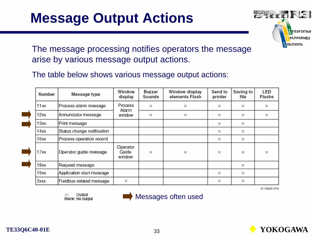
33 YOKOGAWATE33Q6C40-01E
Message Output Actions
The message processing notifies operators the message arise by various message output actions.
The table below shows various message output actions:
Messages often used

34 YOKOGAWATE33Q6C40-01E
Print Message (%PR)
When a print message request is sent from a FCS to an HIS, the operation and monitoring functions print the character string that corresponds to the message number.
The print message may be printed as one in the following formats:
• Comment message plus up to 3 data in order of data 1, data 2 and data 3 may be printed out.
• The integer constant specified in the action column of a sequence table plus 2 process data in order of the integer constant, data 1 and data 2 may be printed out.
The element number of the print message output is as follows: For CS1000: %PR0001 to %PR0100For CS3000: %PR0001 to %PR0200

35 YOKOGAWATE33Q6C40-01E
Print Message (%PR)
An example of the print message definition and its printout are shown below:

36 YOKOGAWATE33Q6C40-01E
Print Message Flow (%PR)The occurrence, transmission and output of print message are shown as below:

37 YOKOGAWATE33Q6C40-01E
Sequence Message Request (%RQ)The sequence message request is sent by the sequential control function at a certain timing to an HIS to execute a processing.
The functions executable with the sequence message request function are as follows:
• Window call• Execution of system function key• Start, stop or restart of batch trend data acquisition• Flashing, turn-on or turn-off of LED• Execution of a program with its program name• Execution of multi-media function• Printout of report
The element numbers of the sequence message request are as follows: For CS1000: %PR0001 to %RQ0100For CS3000: %PR0001 to %RQ0200

38 YOKOGAWATE33Q6C40-01E
Message Request Flow (%RQ)
Sequence function
Report printoutWindow display
Turn-on LED
An example of automatic report printing at the end of the process.

39 YOKOGAWATE33Q6C40-01E
Message Request and SchedulerSequence message request definition window.
Scheduler definition window
Start Time setting and other setting items.

40 YOKOGAWATE33Q6C40-01E
Execution Methods of HIS Functions
HIS functions Program startup LED display Execution method
Function key Possible Turn-on Manual operation by an operator
Scheduler Possible None Automatic execution at a certain time
Sequence message request Possible Turn-on Execution by the
sequence
Function key, scheduler or sequence message request is used to startup HIS functions or programs. Basic functions are almost the same. Only the execution method varies.

41 YOKOGAWATE33Q6C40-01E
Help Message (HW)
Help messages guide the operators as an on-line manual. The messages are displayed in help dialog boxes.Besides the user-defined help, there is the pre-defined system help.
User-defined help:• Up to 9,999 help dialogs can be defined. (HW0001 to HW9999)• Up to 21 lines can be defined per help and 70 characters per line.• Can be related with a function block or a graphic window.

42 YOKOGAWATE33Q6C40-01E
Help Message (HW)
Help message numbers are from HW0001 to HW9999.
Users can define help messages freely.

43 YOKOGAWATE33Q6C40-01E
Help Message Call
Properties window of the function block.
Properties window of the graphic builder.
The help message number related to the function block.
The help message number related to the graphic window.

44 YOKOGAWATE33Q6C40-01E
Message PrintoutMessages besides the sequence message request can be output to a printer.
Generation or recovery is distinguished by the identifier without red printing facility.
For easy-recognition of different type of messages, define number of tabs for each type of message.

45 YOKOGAWATE33Q6C40-01E
Message Printout
• A printer can be assigned for each type of message.
• Messages from the stations excluded from the operation group or function blocks may not be printed.
• Print start position may be defined for each type of message.
• Messages are not printed out until the messages are pilled up to fit one page for print.
• Messages can be printed out at any timing with the function key or the scheduler function.
See IM33S01B30-01E E11 Message Processing.

46 YOKOGAWATE33Q6C40-01E
Message Printout Printer
Define the HIS Printer Name for each type of message with HIS constants definition builder.
Correspondence between Printer Name (device name) and HIS Printer Name can be set with HIS Setupwindow, Printer tab.

47 YOKOGAWATE33Q6C40-01E
Message Printout Timing
Messages are not printed out until the messages are pilled up to fit one page for print. The message, however, may be sent to printer when the defined queuing time elapsed. For each message the queuing time can be defined with HIS constants builder.

48 YOKOGAWATE33Q6C40-01E
Function Keys
CS1000/3000 Engineering Course Textbook
PART-D 6Function Keys

49 YOKOGAWATE33Q6C40-01E
Function Keys
The function keys provided on the operation keyboard allow users to define functions freely.
Executable functions with function keys are follows:
• Window call• Execution of system function key• Start, stop or restart of batch trend data acquisition• Flashing, turn-on or turn-off of LED• Execution of a program with its program name• Execution of multi-media function
The following functions are only for CS3000.• Panel set call • Window call to another station• Remote window call by window name (console type HIS only)• Currently displayed window set copy (console type HIS only)• Remote CRT window erase (console type HIS only)
See IM33S01B30-01E PART-E Human Interface Station, E13.2 Function Keys.

50 YOKOGAWATE33Q6C40-01E
Window Call Function
To assign the window call function to the function keys, define the following functions with the function key definition builder.
• Window typeGraphic window, system status display window and so on.
• Window calling function typeTUN, TREND, DRAW and so on.
• Window display sizeLarge size, medium size and others.
• Window display position Defined with X-Y co-ordinates.
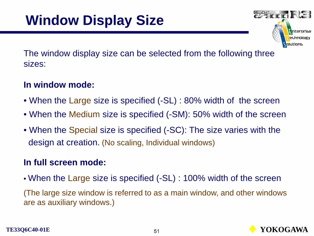
51 YOKOGAWATE33Q6C40-01E
Window Display Size
The window display size can be selected from the following three sizes:
In window mode:
• When the Large size is specified (-SL) : 80% width of the screen• When the Medium size is specified (-SM): 50% width of the screen
• When the Special size is specified (-SC): The size varies with thedesign at creation. (No scaling, Individual windows)
In full screen mode:
• When the Large size is specified (-SL) : 100% width of the screen(The large size window is referred to as a main window, and other windows are as auxiliary windows.)

52 YOKOGAWATE33Q6C40-01E
Window Display Position
The window display position can be specified beforehand.The display position is specified using X and Y coordinates.The range falls within 0 to 32767.The display position is specified in the format given below:
= +X coordinate + Y coordinate
X coordinate: The left edge of the screen is set as the origin.
Y coordinate: The upper edge of the screen is set as the origin.
200
100
(+200,+100)
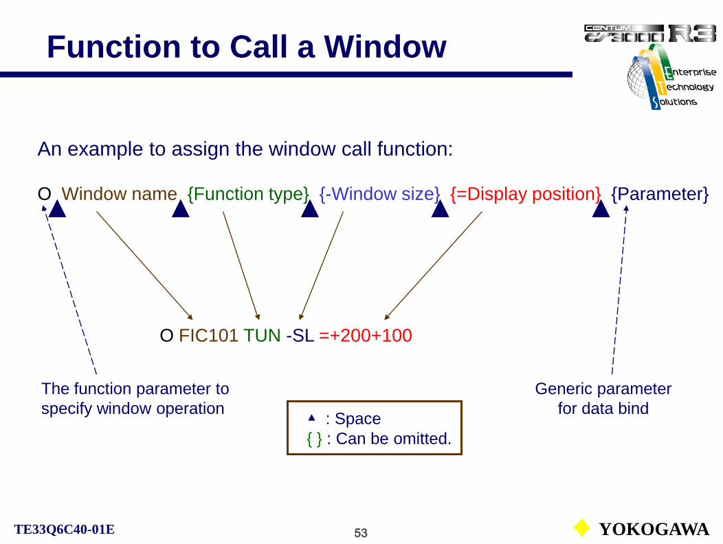
53 YOKOGAWATE33Q6C40-01E
Function to Call a Window
An example to assign the window call function:
O Window name {Function type} {-Window size} {=Display position} {Parameter}
O FIC101 TUN -SL =+200+100
▲ : Space{ } : Can be omitted.
Generic parameter for data bind
The function parameter to specify window operation

54 YOKOGAWATE33Q6C40-01E
Functions of Function Keys
Function parameter list:
See IM33S01B30-01E E13.
O: Window callK: Execution of system function keyT: Start, stop or restart of batch trend data acquisitionE: Flashing, turn-on or turn-off of LEDF: Execution of a program with its program nameX: Execution of multi-media function
The following functions are only for CS3000.P: Panel set call S: Window call to another station
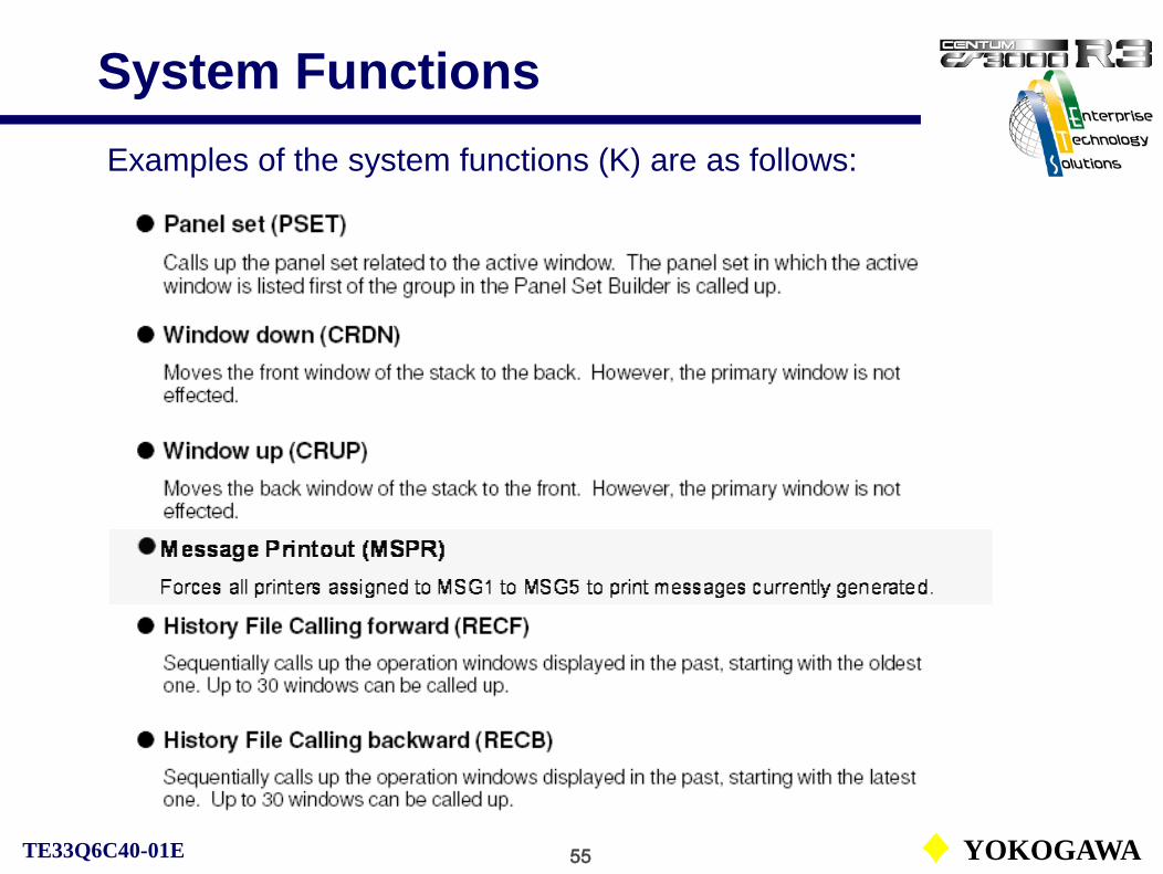
55 YOKOGAWATE33Q6C40-01E
System FunctionsExamples of the system functions (K) are as follows:

56 YOKOGAWATE33Q6C40-01E
Function Key Assignment
Function key definition file (FuncKey) in CONFIGURATION folder of HIS.
An example of the function key definition:

57 YOKOGAWATE33Q6C40-01E
Temporary AssignmentFunction key definition window in the HIS Setup.
The functions assigned to the function keys by the HIS Setup are temporary. When the HIS definition is loaded from the System View, assigned functions are initialized to the builder definition.

58 YOKOGAWATE33Q6C40-01E
Other Functions
CS1000/3000 Engineering Course Textbook
PART-D 7Other Functions
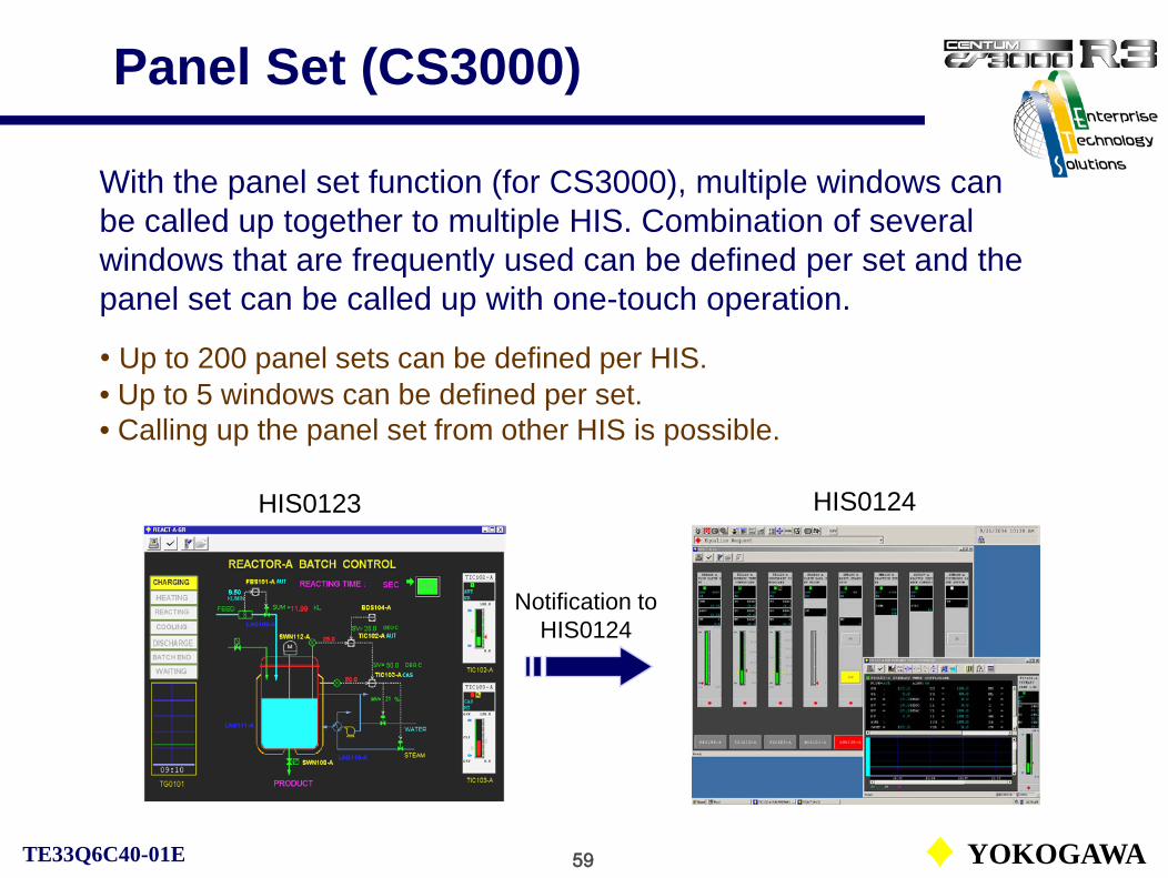
59 YOKOGAWATE33Q6C40-01E
Panel Set (CS3000)
With the panel set function (for CS3000), multiple windows can be called up together to multiple HIS. Combination of several windows that are frequently used can be defined per set and the panel set can be called up with one-touch operation.
• Up to 200 panel sets can be defined per HIS.• Up to 5 windows can be defined per set.• Calling up the panel set from other HIS is possible.
HIS0123 HIS0124
Notification to HIS0124
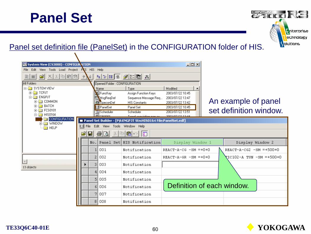
60 YOKOGAWATE33Q6C40-01E
Panel Set
An example of panel set definition window.
Panel set definition file (PanelSet) in the CONFIGURATION folder of HIS.
Definition of each window.

61 YOKOGAWATE33Q6C40-01E
Plant Hierarchy
The plant hierarchy refers to the various equipment in the plant control system that are organized into layered architectures based on ISA S88.01 physical model.
The plant hierarchy is useful in setting security, filtering process messages, flashing function key LEDs and performing other operations.

1 YOKOGAWATE33Q6C40-01E
Sequential Control Functions
CS1000/3000 Engineering Course Textbook
PART-ESequential Control Functions

2 YOKOGAWATE33Q6C40-01E
Sequential Control Functions
CS1000/3000 Engineering Course TextbookPART-E Sequential Functions
Reference: IM33S01B30-01EPART-D Function Block Details, D3 Sequence Control
E1. Sequential Control PositioningE2. Types of Sequential Control BlocksE3. Sequence ConnectionE4. Sequence Table BlocksE5. Logic Chart BlockE6. Processing Timing of SequenceE7. Switch Instrument BlocksE8. Timer BlockE9. Software Counter BlockE10. Relational Expression BlockE11. Auxiliary Blocks

3 YOKOGAWATE33Q6C40-01E
Sequential Control Function
CS1000/3000 Engineering Course Textbook
PART-E 1Sequential Control Positioning

4 YOKOGAWATE33Q6C40-01E
Sequential Control PositioningThe function blocks that execute the sequential control are referred to as sequential control blocks. The positioning of the sequential control blocks is shown blow:
FCS
Basic control Software I/O
I/O interfaces

5 YOKOGAWATE33Q6C40-01E
Types of Sequential Control
Definition of sequential control:Sequential control executes in sequence each control step
following the pre-defined conditions or orders.
The sequential control can be divided into following two types:
• Condition control (Monitoring)Monitors process status and controls according to the pre-defined
conditions.
• Programmed control (Phase steps)Controls according to the pre-defined programs (phases).
6 YOKOGAWATE33Q6C40-01E
Sequential Control Description
SFC (Sequential Function Chart ) block:The SFC is a graphical programming language suitable for describing a process control sequence. It is standardized by the international standard, IEC SC65A/WG6.It is used for relatively large-scaled sequential controls and device controls. The SFC block defines the flow of an entire sequence. Each step in the SFC is described with sequence tables or SEBOL (Sequence and Batch Oriented Language).
Logic chart block:The logic chart block aligns each condition and operation, and the combination of conditions is described with logic elements to specify the operation performed. This is suitable for describing the condition control type such as an interlock sequence.
Sequence table block:The conditions and operations are arranged in the decision table format and specifies which operation is performed by the combination of conditions. This table is suitable for describing the both types of sequence.

7 YOKOGAWATE33Q6C40-01E
Types of Sequential Control Blocks
CS1000/3000 Engineering Course Textbook
PART-E 2Types of Sequential Control Blocks

8 YOKOGAWATE33Q6C40-01E
Types of Sequential Control Blocks
Sequence table blocks:The sequence table block realizes a sequential control by operating other function blocks and/or process I/O or software I/O.
SFC blocks:The SFC block executes the sequential control program described with SFC.
Logic chart block:The logic chart block realizes an interlock sequence with the logic chart diagram using logic elements.
Sequence table and logic chart are explained in this engineering course.

9 YOKOGAWATE33Q6C40-01E
Types of Sequential Control Blocks
Sequence auxiliary blocks:The following types of blocks are provided.
Timer block (TM) Relational expression block (RL)Soft-counter block (CTS) Resource scheduler block (RS)Pulse train counter block (CTP) Valve monitoring block (VLVM)Code input block (CI)Code output block (CO)
The sequence auxiliary blocks are registered from the Select Function Block dialog. There are two folders; Sequence Elements 1 and Sequence Elements 2.
See PART-E11, Auxiliary Blocks.

10 YOKOGAWATE33Q6C40-01E
Types of Sequential Control Blocks
Switch instrument blocks*:The switch instrument block monitors and operates devices such as ON/OFF valves, motors or pumps, or final control elements for contact I/O.
* The switch instrument blocks are explained in detail later.
Valve pattern monitor block (Optional):The valve pattern monitor is a function block which runs in an FCS (Field Control Station). One valve pattern monitor can simultaneously monitor a maximum of 512 valves.This valve pattern monitor is controlled by the user application represents an operation scripted in SEBOL statements.

11 YOKOGAWATE33Q6C40-01E
Sequence Connection
CS1000/3000 Engineering Course Textbook
PART-E 3Sequence Connection

12 YOKOGAWATE33Q6C40-01E
Sequence Connection
The sequence connection specifies various elements having data as the connection destinations for I/O terminals of a function block. The conditional expression to test data status for the input terminal, and the data to manipulate an element for the output terminal should be specified.
The processing for reading data from the connection destination is referred to as [Condition testing], while the processing to output data to the connection destination is referred to as [Status manipulation]. Connection information formats are as follows:
Element symbol name. Data item name. Condition specificationElement symbol name. Data item name. Action specification
Since the wiring between terminals can describe only an element symboland a data item, the sequence connection is directly described on the sequence block without wiring.

13 YOKOGAWATE33Q6C40-01E
Sequence Table Blocks
CS1000/3000 Engineering Course Textbook
PART-E 4Sequence Table Blocks

14 YOKOGAWATE33Q6C40-01E
Sequence Table Blocks The sequence table block provides two types of table in the form of a decision table.
(1) ST16 (Basic):The ST16 block handles a total of 64 I/O (condition/action) signals and 32 rules. Number of I/O signals can be exchanged in the unit of 8.
(2) ST16E (Extension):The ST16E is used for the rule extension. It is connected to the extending ST16.
32 rules
Total 64 I/O points (fixed)
Condition rules
Action rules
Input condition
Output action
Y NY N
Y Y N
Total 64 I/O points (fixed)
Input condition
Output action
Y NY N
Y Y N
Condition rules
Action rules
32 rules

15 YOKOGAWATE33Q6C40-01E
M- and L- Size Sequence TablesBesides the sequence table blocks ST16 and ST16E, two larger size tables are provided. The tables of each size have basic and extension types.
Middle size table: M-ST16, M-ST16E Large size table: L-ST16, L-ST16E
(1) M-ST16, M-ST16E:The M-ST16 and M-ST16E blocks handle a total of 96 I/O (condition/action) signals and 32 rules.
(2) L-ST16, L-ST16E:The L-ST16 and L-ST16E blocks handle a total of 128 I/O (condition/action) signals and 32 rules.

16 YOKOGAWATE33Q6C40-01E
Rule Extension (ST16E)The number of rules in a single sequence table is fixed at 32 and cannot be changed. However, if the number of rules in a sequence table is not enough to describe one phase unit, the number of rules can be extended by connecting to another sequence table.
• Up to 100 steps can be described in a sequence table group.• The same step label cannot be described in more than one step label setting area.• The step executed over two sequence tables or more cannot be described.• The extended sequence table and the extending sequence table should be described in the same control drawing.
Sequence table group

17 YOKOGAWATE33Q6C40-01E
Rule Extension (ST16E)
Rule extension sequence table block (ST16E):Since the ST16E is managed by the extending sequence table block ST16, the ST16E cannot be activated independently.The ST16E can only be connected to a step-type sequence table block. It cannot be connected to a non-step type sequence table. (Connection is unnecessary.)
Step 1 to 15 Step 16 to 35

18 YOKOGAWATE33Q6C40-01E
Sequence Table Block
I/O signals Total 64(fixed)
Condition signalsTotal 32 (default)
32 rules
Input connection information
Condition specification
Condition rules
Action rulesAction signalsTotal 32 (default)
Output connection information
Action specification

19 YOKOGAWATE33Q6C40-01E
Sequence Table Block
Action signal
comment
Condition signal
comment
Step label
Next step label
Rule expansion destination tag name
Processing timing Scan period
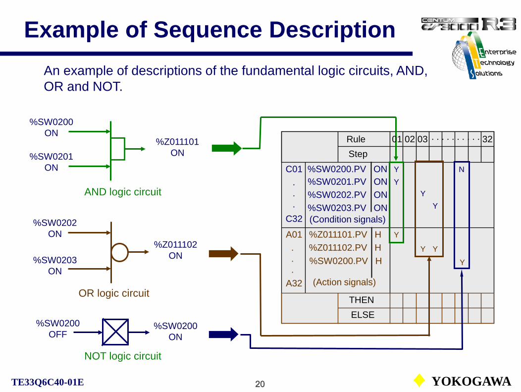
20 YOKOGAWATE33Q6C40-01E
Example of Sequence DescriptionAn example of descriptions of the fundamental logic circuits, AND, OR and NOT.
%SW0200ON
AND logic circuit
OR logic circuit
C01
C32
RuleStep
(Condition signals)
YY
Y
.
.
.
A01
A32
THENELSE
(Action signals)
.
.
.
%Z011101.PV H%Z011102.PV H%SW0200.PV H
Y
YY
Y
%SW0201ON
%SW0202ON
%SW0203ON
%Z011101ON
%Z011102ON
%SW0200OFF
NOT logic circuit
%SW0200ON
N
Y
01 32. . . . . . . . . .02 03
%SW0201.PV ON%SW0202.PV ON
%SW0200.PV ON
%SW0203.PV ON
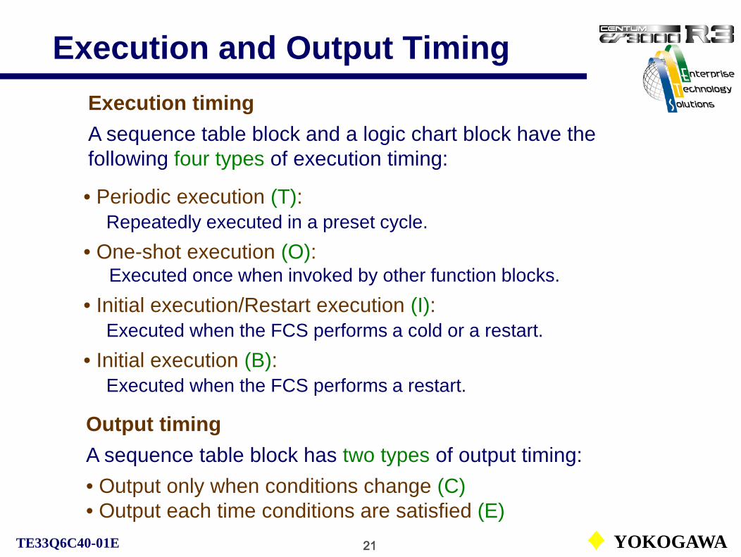
21 YOKOGAWATE33Q6C40-01E
Execution and Output TimingExecution timingA sequence table block and a logic chart block have the following four types of execution timing:
• Periodic execution (T):Repeatedly executed in a preset cycle.
• One-shot execution (O):Executed once when invoked by other function blocks.
• Initial execution/Restart execution (I):Executed when the FCS performs a cold or a restart.
• Initial execution (B):Executed when the FCS performs a restart.
Output timingA sequence table block has two types of output timing:• Output only when conditions change (C)• Output each time conditions are satisfied (E)

22 YOKOGAWATE33Q6C40-01E
Output Timing• Output only when conditions change (C):The action is executed only once when the condition is switched from false to true. However, if the non-latched output is specified for the action signal, the action changes when the condition is switched from true to false.
• Output each time conditions are satisfied (E):The action is executed each control period as long as the condition remains true.
Output only when conditions change (C)
Condition
ON
OFFCondition
ON
OFF
Output
Output each time conditions are satisfied (E)
Output
Non-latched type (L type)

23 YOKOGAWATE33Q6C40-01E
Processing Timing
Execution timing and output timing can be used in combination. The table below shows the combination of timings for ST16 and ST16E. Default
For the LC64, logic chart block, output timing (C) can not be specified.
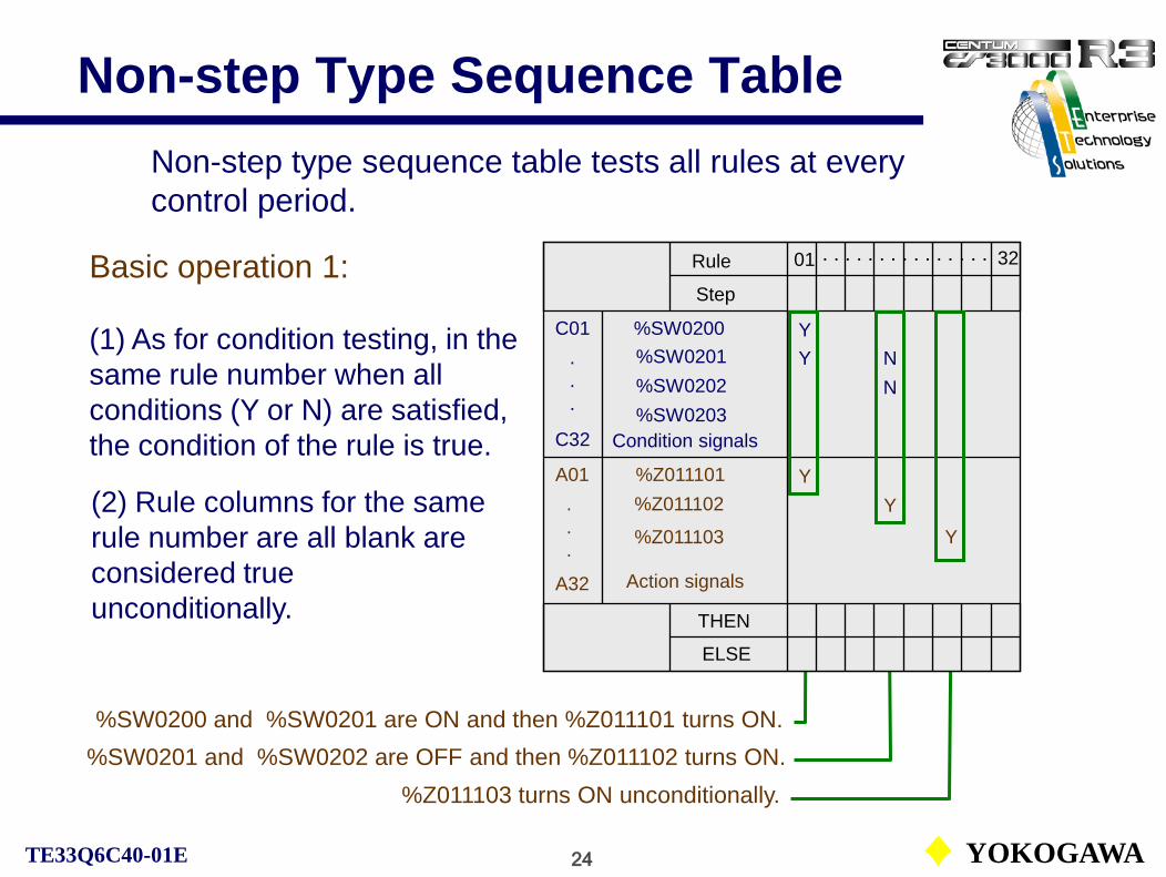
24 YOKOGAWATE33Q6C40-01E
Non-step Type Sequence Table
Basic operation 1:
(1) As for condition testing, in the same rule number when all conditions (Y or N) are satisfied, the condition of the rule is true.
(2) Rule columns for the same rule number are all blank are considered true unconditionally.
Non-step type sequence table tests all rules at every control period.
%SW0200 and %SW0201 are ON and then %Z011101 turns ON.%SW0201 and %SW0202 are OFF and then %Z011102 turns ON.
%Z011103 turns ON unconditionally.
C01
C32
A01
A32
THEN
ELSE
01 32Rule
Step
Condition signals
Action signals
Y%SW0201%SW0202
%SW0200Y
Y%Z011101%Z011102
N
Y
%SW0203
N
.
.
.
.
.
.
%Z011103 Y
. . . . . . . . . . . . . . .

25 YOKOGAWATE33Q6C40-01E
Non-step Type Sequence Table
Basic operation 2:
When multiple action signals exist in a condition satisfied rule, the actions are executed from top to down.
C01
C32
A01
A32
THENELSE
01 32RuleStep
Condition signals
Action signals
Y%SW0201%SW0202
%SW0200Y
Y%Z011101%Z011102
%SW0203
.
.
.
.
.
.
%Z011103YN
Actions are executed in order of %Z011101, %Z011102, %Z011103.
. . . . . . . . . . . . . . .

26 YOKOGAWATE33Q6C40-01E
Non-step Type Sequence Table
Basic operation 3:
When the conditions of multiple rules are satisfied simultaneously with respect to a single operation, if requests for both Y and N are detected, Y has a priority and the operation for N is not executed.
When conditions in 3 rules are satisfied, Y is executed. (Y has a priority.)
C01
C32
A01
A32
THENELSE
01 32RuleStep
Condition signals
Action signals
Y%SW0201%SW0202
%SW0200Y
Y%Z011101%Z011102
%SW0203
.
.
.
.
.
.
%Z011102
N
YY
N
When conditions in 2 rules are satisfied, Y and then N is executed. ( Executed from top to down.)
NY
YY
. . . . . . . . .

27 YOKOGAWATE33Q6C40-01E
Example of Non-step Sequence
Always monitors not to overflow the buffer tank.
HH alarm logic flow.
- Closed- Open

28 YOKOGAWATE33Q6C40-01E
Example of Non-step Sequence
Description of HH alarm logic flow in the previous example:

29 YOKOGAWATE33Q6C40-01E
Step Type Sequence Table
THEN
ELSE
08
Rule
Step
YY
Y
C01
C32 Condition signals
%SW0201%SW0202
%SW0200
%SW0203
.
.
.
A01
A32 Action signals
%Z011101%Z011102.
.
. %Z011103
04 05
0508
Basic operation 1:
For the step type sequence table, the next execution step label must be described in the THEN/ ELSE column in order to advance the steps.
The step will not advance if both next step labels in the THEN/ ELSE are blank. The same step is executed each time.
Step label
Next step label (THEN label)
Next step label (ELSE label)
Step type sequence table tests only rules in the current step at every control period.
YY
Y
Y
Tested rules

30 YOKOGAWATE33Q6C40-01E
Step Type Sequence Table
Basic operation 2:
The next step specified in the THEN column is the step to advance when the condition test result is true.
When all actions for the corresponding rules are executed, the step proceeds to the next step.
When the condition of the rule in step 04 is satisfied, the step advances to 05.
THENELSE
08RuleStep
YY
Y
C01
C32 Condition signals
%SW0201%SW0202
%SW0200
%SW0203
.
.
.
A01
A32 Action signals
%Z011101%Z011102.
.
.%Z011103
04 05
0508
YY
YY

31 YOKOGAWATE33Q6C40-01E
Step Type Sequence Table
Basic operation 3:
The next step specified in the ELSE column is the step to advance when the condition test result is false.
When conditions for the corresponding rules are not satisfied, the step proceeds to the next step without executing the actions.
When the condition of the rule in step 04 is not satisfied, the step advances to 08.
THENELSE
08RuleStep
YY
Y
C01
C32 Condition signals
%SW0201%SW0202
%SW0200
%SW0203
.
.
.
A01
A32 Action signals
%Z011101%Z011102.
.
.%Z011103
04 05
0508
YY
YY

32 YOKOGAWATE33Q6C40-01E
Step Type Sequence Table
Basic operation 4:
The same step label can be assigned to the multiple rules. In this case, according to the condition, branched actions can be performed.
If there are multiple step transition requests in the same step (multiple conditions are satisfied), the step advances to the next step label that is described on the smallest rule number.
If all multiple conditions are satisfied, the next step is “02”.
C01
C32
A01
A32
THENELSE
04
Action signals
Y
%Z011101%Z011102
RuleStep
Condition signals
%SW0201%SW0202
%SW0200
%SW0203
.
.
.
.
.
.
%Z011103
YY
01 02
02 03 04
03
YY
Y

33 YOKOGAWATE33Q6C40-01E
Step Type Sequence Table
Basic operation 5:
When a step advances to a next step, the next step is executed at the next scan period.
When a step has advanced, the conditions of each rule are initialized once.
The step sequence executes only a single step at each scan period.In this case, it may take 2 seconds or more to turn %Z011103 OFF, after the step 01 was executed.
C01
C32
A01
A32
THENELSE
04RuleStep
Condition signals
Action signals
Y%SW0201%SW0202
%SW0200Y
Y%Z011101%Z011102
%SW0203
.
.
.
.
.
.
03
%Z011103 NN
01 02
02 03 04

34 YOKOGAWATE33Q6C40-01E
Step Type Sequence Table
Basic operation 6:
Step label 00 is executed at each period. The step 00 can be described only at the head of a sequence table group. * 1. The step 00 cannot be described as a next step label.
* 2. The step 00 cannot be described on an extended sequence table.
The step 00 as well as the current step 03, conditions are tested. If conditions of step 00 are satisfied, actions are executed.
Current step.
C01
C32
A01
A32
THENELSE
00 04RuleStep
Condition signals
Action signals
Y%SW0201%SW0202
%SW0200Y
Y%Z011101%Z011102
%SW0203
.
.
.
.
.
.
03
%Z011103 N
YY
N
01 02
02 03 04
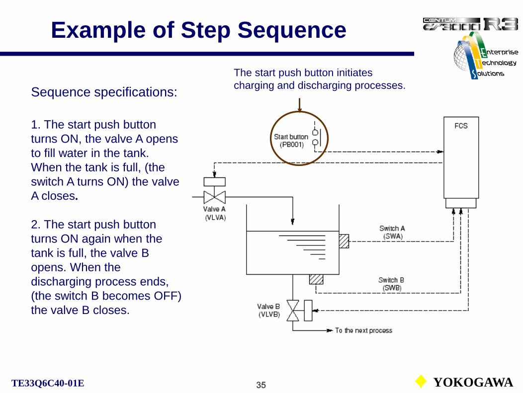
35 YOKOGAWATE33Q6C40-01E
Example of Step SequenceThe start push button initiates charging and discharging processes.Sequence specifications:
1. The start push button turns ON, the valve A opens to fill water in the tank. When the tank is full, (the switch A turns ON) the valve A closes.
2. The start push button turns ON again when the tank is full, the valve B opens. When the discharging process ends, (the switch B becomes OFF) the valve B closes.

36 YOKOGAWATE33Q6C40-01E
Example of Step Sequence
Charging process (step A1)
Rule number 01
Rule number 02
Rule number 03
Rule number 04
Discharging process (step A2)
Close

37 YOKOGAWATE33Q6C40-01E
Example of Step Sequence
Description of the sequence with a sequence table.
B

38 YOKOGAWATE33Q6C40-01E
Condition and Action Signal Allocation
The sequence table block (ST16) has 32 condition signals and 32 action signals (default). However, allocation of the number of signals can be changed in the 8-signal unit with the signal selection dialog in the function block detail definition builder.
No. of condition signals No. of action signals
8 5616 4824 4032 (default) 32 (default)40 2448 1656 8

39 YOKOGAWATE33Q6C40-01E
Logic Chart Block
CS1000/3000 Engineering Course Textbook
PART-E 5
Logic Chart Block

40 YOKOGAWATE33Q6C40-01E
Logic Chart Block (LC64)
A logic chart block is the function block that describes the relations of the input signals, the output signals and logic calculation operators in the interlock dialog form.
An architecture of LC64 logic chart block shown below:
J32Q32
A logic chart block LC64 has 32 inputs, 32 outputs and 64 logic elements.

41 YOKOGAWATE33Q6C40-01E
Logic Chart Example
The figure below shows an example of the logic chart:

42 YOKOGAWATE33Q6C40-01E
Outline of Logic Chart
• Order of logic calculation:For the execution of logic calculation, the matrix expansion or the manual expansion can be selected.
• Comment:For the input signals or output signals, their service comments can be described up to 24 characters.
• Logic chart area:Logic calculation process can be expressed in logic chart diagram form.
• Condition/Action signals:The input/output information such as tag names, data items or other specific condition/action scripts should be entered.

43 YOKOGAWATE33Q6C40-01E
Creating a Logic Chart Block
• Logic chart edit window:From the selection dialog, select LC64 to display a logic chart edit window.

44 YOKOGAWATE33Q6C40-01E
Logic Chart Processing Flow
The figure below shows a logic chart processing flow:
• Input processing:The condition test is performed on the input signal.
• Logic calculation processing:The logic calculation is expressed by combinations of logic operators.
• Output processing:The status manipulation sends commands such as data setting or status change to the contact output terminals or other function blocks.
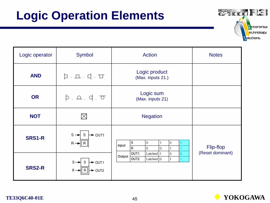
45 YOKOGAWATE33Q6C40-01E
Logic Operation Elements
Logic operator Symbol Action Notes
ANDLogic product(Max. inputs 21.)
ORLogic sum
(Max. inputs 21)
NOT Negation
SRS1-R
SRS2-R
Flip-flop(Reset dominant)

46 YOKOGAWATE33Q6C40-01E
Logic Operation Elements
Logic operator Symbol Action Notes
Wipeout
OND
SRS1-S
SRS2-S
Flip-flop(Set dominant)
OFFD
WOUT (W.O)
ON-delay timer
OFF-delay timer
tIN
OUT
tIN
OUT

47 YOKOGAWATE33Q6C40-01E
Logic Operation Elements
Logic operator Symbol Action Notes
ComparatorCMP-GE
TON
TOFF
One-shot(Rise trigger)
CMP-EQ
CMP-GT Comparator
Comparator
One-shot(Fall trigger)
IN
OUT
IN
OUT
1 scan
1 scan

48 YOKOGAWATE33Q6C40-01E
Wipeout Operation
A logic table and an equivalent circuit of the wipeout (WOUT) is shown below:
OUTS
R
One wipeout operation is counted as two logic operation elements.

49 YOKOGAWATE33Q6C40-01E
Internal Timer Operation
Operation diagram of the timer is shown below:

50 YOKOGAWATE33Q6C40-01E
Execution Order
For the execution of logic calculation, the matrix expansion or manual expansion can be selected.
• Matrix expansion:Logic operators are executed from the left column to the right, and from the upper element to the lower in the same column.
• Manual expansion:The execution order automatically assigned to the logic operation elements according to their position that can be manually changed.
The execution order can be specified on the logic chart edit window. The default setting is the matrix order.

51 YOKOGAWATE33Q6C40-01E
Processing Timing of Sequence
CS1000/3000 Engineering Course Textbook
PART-E 6Processing Timing of Sequence

52 YOKOGAWATE33Q6C40-01E
Execution Timing
A sequential control block and a logic chart block have the following four types of execution timing:
• Periodic execution (T):Repeatedly executed in a preset cycle.
• One-shot execution (O):Executed once when invoked by other function blocks.
• Initial execution/Restart execution (I):Executed when the FCS performs a cold or a restart.
• Initial execution (B):Executed when the FCS performs a restart.

53 YOKOGAWATE33Q6C40-01E
Output Timing
• Output only when conditions change (C):The ST16, ST16E blocks output an operation signal only at the
timing when the tested conditions are changed from unsatisfied to satisfied. This output timing can only be specified with the periodic execution (T) or the one-shot execution.
• Output each time conditions are satisfied (E):The ST16 ,ST16E blocks output an action signal every scan period
as long as the tested conditions are satisfied.
For the LC64, logic chart block, only “Output each time conditions are satisfied (E)” can be specified.
The output timing of a sequence table block indicates the conditions under which output processing is performed when the sequence table is executed periodically or as one-shot.

54 YOKOGAWATE33Q6C40-01E
Execution timing and output timing can be used in combination. The table below shows the combination of timings for ST16 and ST16E. Default
Processing Timing
For the LC64, logic chart block, output timing (C) can not be specified.

55 YOKOGAWATE33Q6C40-01E
Control Period and Control Phase
• Control period:The execution interval at which the periodic execution type ST16 or
ST16E block executes the sequence table. (Specify the value between 1 and 16 seconds)
• Control phase:The execution timing of the sequence table. It is the execution timing
relative to the execution timing of the phase-zero sequence table.
The control phase can be set on the sequence table, which control period is more than one second.

56 YOKOGAWATE33Q6C40-01E
Control Period and Control PhaseThe sequence table, which control period is 5 sec, and control phase is 3 sec. The table is executed at every 5 seconds interval, 3 seconds after the phase-zero table.
Executed every second.
Executed with 5 sec. control period and 3 sec. control phase.
Base Base Base

57 YOKOGAWATE33Q6C40-01E
Switch Instrument Blocks
CS1000/3000 Engineering Course Textbook
PART-E 7Switch Instrument Blocks

58 YOKOGAWATE33Q6C40-01E
Concept of Switch Instrument
Magnet valve with limit switches
Manipulated outputDO001
OPEN
CLOSE
OPEN
CLOSE画面から直接DOを操作してバルブを開閉する
画面から直接DIでバルブの開閉を確認
V1024
AUT
OPEN
CLOSE
Cutoff Valve
The contact output is assigned as the MV of an instrument.
Related contact output and input modules are operated and monitored as a single instrument.
The contact input is assigned as the PV of an instrument.
Monitoring inputDI001

59 YOKOGAWATE33Q6C40-01E
Structure of Switch Instrument
Remote output value
OUTIN
INT
TSI
SW1
Answerback input function
CAL
Answerback check function
Remote/Local input function
Output signal conversion function
BPSW=0
Sequence setpoint
Conformity check of PV and MV after answerback check suppression time.
Answerback bypass function
PV
BPSW=1
BPSW=0 BPSW=1
ROUT
MAN
CAS,AUT
MV
CSVRMV
RSW
Remote(0) / Local(1)Answerback (PV) Output (MV)
Answerback bypass
Mode change interlock

60 YOKOGAWATE33Q6C40-01E
Concept of Switch InstrumentTAG NO.
AUT
OPEN
CLOSE
xxxxxxxx
MAN
Local operation board
Open
Close
Limit switch
Functions of switch instrument
Instrument faceplateThe switch instrument block
(SIO-22) manipulates a valve by its output (MV) and confirms the status of the valve by the limit switch input (PV).
Answerback check function
Sequence table
AUT
LOCAL
MV PV PV=0: OFFPV=2: ON
MV=0: OFFMV=2: ON

61 YOKOGAWATE33Q6C40-01E
Answerback Check and Types
Switch instrument types:The following 10 types of blocks are provided.
SI - 1 SI - 2 SO - 1 SO - 2SIO – 11 SIO – 12 SIO – 21 SIO - 22SIO – 12P SIO – 22P
Block symbols: SIO – 22P
Switch instrument Input Output No. of input No. of output Pulse I/O
Answerback check function:The answerback check function checks if final control elements such as a valve is working as specified by the output from the switch instrument block.If there is any inconsistency between the answerback input value (PV) and the manipulated output value (MV), the answerback error alarm (ANS+ or ANS-) occurs.As it takes a certain length of time from changing the manipulated output value to completing the final control element operation, answerback check suppression time (MTM) can be specified.
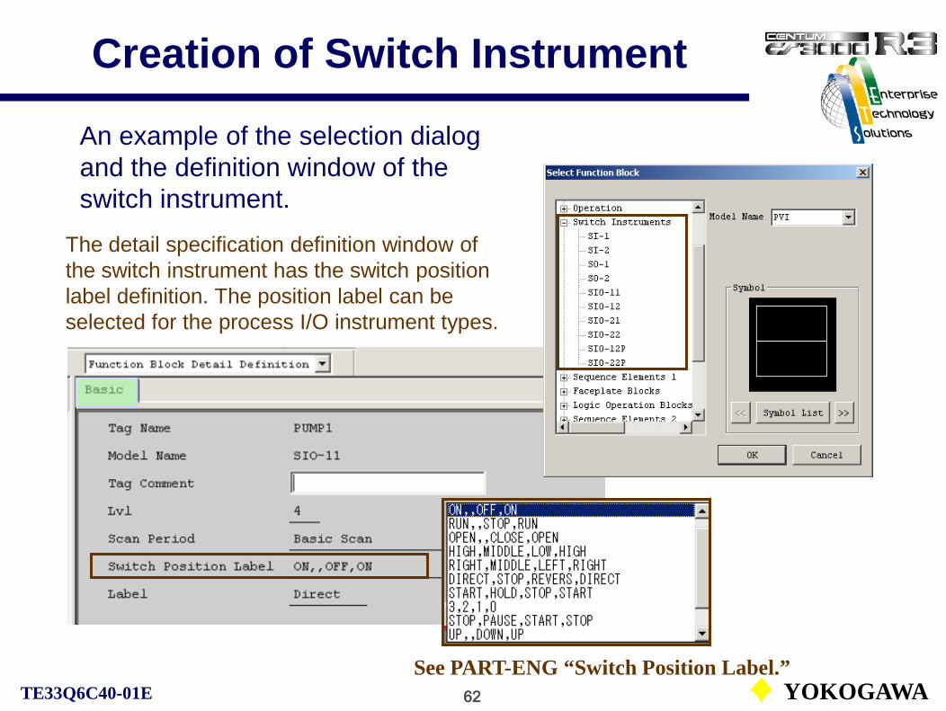
62 YOKOGAWATE33Q6C40-01E
Creation of Switch Instrument
An example of the selection dialog and the definition window of the switch instrument.
The detail specification definition window of the switch instrument has the switch position label definition. The position label can be selected for the process I/O instrument types.
See PART-ENG “Switch Position Label.”

63 YOKOGAWATE33Q6C40-01E
Timer Block
CS1000/3000 Engineering Course Textbook
PART-E 8Timer Block

64 YOKOGAWATE33Q6C40-01E
Timer Block (TM)The timer block (TM) measures time in the unit of second or minute. In addition to the basic elapsed time measuring function, it has the preset timer function, which notifies time-up when a specified time elapsed. It has the function of periodic action too.
Function block diagram
OUTPV
(CTUP)
Counting process
BSTS: Block statusCTUP: Count-up
OP: OperationSTART: Start/stop action
Start command
%SW0500.PV ON
TM100.BSTS CTUP
TM100.OP START
Y
Y
Y
N
An example of the timer block operation.
Timer count-up
Stop command
Timer start/stop
Timer start switch
%SW0500.PV H NStart switch off
Processing Timing: TC

65 YOKOGAWATE33Q6C40-01E
Action of Timer BlockWhen the timer block receives an action command, the block status changes according to the command. When a start command is given, the block resets the elapsed time (PV), and starts counting.
Preset value (The time up to time-up.)
Pre-alarm value
Counted time
Deviation (PH-PV)

66 YOKOGAWATE33Q6C40-01E
Timer Restart Action
When the timer block in pause status receives the restart command, the counting action is restarted. (Elapsed time is not reset.)
NR

67 YOKOGAWATE33Q6C40-01E
Condition and Action Signals
Tag name.Data item Data Action rule TM0002.OP START Y (N for stop)TM0002.OP STOP YTM0002.OP WAIT Y (N for restart)TM0002.OP RSTR Y
Timer Start ActionTimer Stop ActionTimer Pause ActionTimer Restart Action
Tag name.Data item Data Condition rule TM0002.BSTS (Block status) Y / N
The following describes examples of the timer condition and action signals can be specified in the sequence table:

68 YOKOGAWATE33Q6C40-01E
Software Counter Block
CS1000/3000 Engineering Course Textbook
PART-E 9Software Counter Block
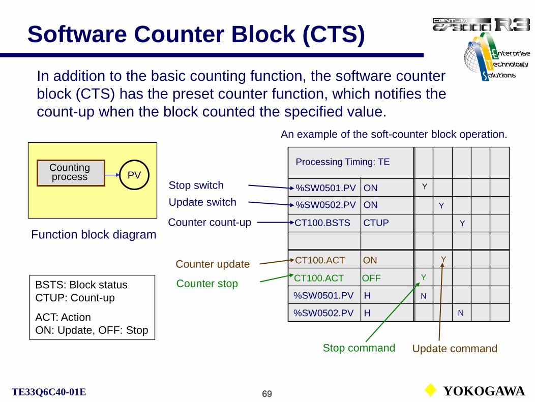
69 YOKOGAWATE33Q6C40-01E
Software Counter Block (CTS)In addition to the basic counting function, the software counter block (CTS) has the preset counter function, which notifies the count-up when the block counted the specified value.
Function block diagram
PVCounting process
BSTS: Block statusCTUP: Count-up
ACT: ActionON: Update, OFF: Stop
%SW0502.PV ON
CT100.ACT ON
Y
Y
YCT100.ACT OFF
Update commandStop command
Y
Counter count-up
Counter update
Counter stop
Update switch
%SW0501.PV H N
Processing Timing: TE
An example of the soft-counter block operation.
CT100.BSTS CTUP
%SW0501.PV ONStop switch
%SW0502.PV H
Y
N

70 YOKOGAWATE33Q6C40-01E
Action of Software Counter BlockThe software counter block (CTS) updates the count value (PV) upon receiving the operation command and changes the block status. When the operation command is received, if the block status is STOP, the count value is reset (PV=1).
Preset value (Count-up value)
Pre-alarm value
Counted value
NR

71 YOKOGAWATE33Q6C40-01E
Condition and Action Signals
Tag name.Data item Data Action rule CTS001.ACT ON YSoft-counter Update Action
Soft-counter Stop Action
Tag name.Data item Data Condition rule CTS001.BSTS (Block status) Y / N
The following describes examples of the soft-counter condition and action signals can be specified in the sequence table:
CTS001.ACT OFF Y

72 YOKOGAWATE33Q6C40-01E
Relational Expression Block
CS1000/3000 Engineering Course Textbook
PART-E 10Relational Expression Block

73 YOKOGAWATE33Q6C40-01E
Relational Expression Block (RL)The relational expression block (RL) is executed during the condition testing for a sequence control block such as a sequence table, or for a calculation block. It tests the numerical relationship or the logical product of two data, according to the relational expression in the block, and returns the result whether it matches for the conditions to the calling function block.
Flow AFlow B
RV01
RV02(X01)
RV31
RV32(X16)Flow C
2.50
FlowFlow A
Flow B
Flow A (RV01) > Flow B (RV02)
Flow A (RV01) < Flow B (RV02)

74 YOKOGAWATE33Q6C40-01E
Relational Expression Block (RL)
There exists two types of the relational expressions:The numerical comparison operation between two data and the logical product operation of two data.
• Numerical comparison (CMP):Performs the numerical comparison of two data. It tests if the
relationship matches for the relational expression and returns a logical value.
e.g. FIC101.PV > FIC102.PV
• Logical product (AND):Computes logical products of two data by bit. It returns true if at
least one bit satisfies the relational expression.
e.g. %CI0100.PV & %CI0101.PV

75 YOKOGAWATE33Q6C40-01E
Relational Expression Block (RL)
Selection of the operator.
RV01 RV04
X 01
The definition of the relational expression block and the description on sequence tables:
The defined relational expressions are described on the sequence table as follows: RL0100 is a user tag of the relational expression block (RL).
The figure below shows an example of the relational expression definition.
RL0100.X01
TM100.OP
Y
Y
Y
N
RL0100.X01
GELT
START
RV03 RV02
X 02
[Data Expression (Numerical)] GT: Greater thanGE: Greater than and equalLT: Less thanLE: Less than and equalEQ: Equal
DataTag, Data item
76 YOKOGAWATE33Q6C40-01E
Auxiliary Blocks
CS1000/3000 Engineering Course Textbook
PART-E 11Auxiliary Blocks

77 YOKOGAWATE33Q6C40-01E
Creation of Sequence Auxiliary
The sequence auxiliary blocks are registered from the Select Function Block dialog. There are two folders; Sequence Elements 1 and Sequence Elements 2.
Sequence Elements 1:TM (Timer), CTS (Soft-counter), CTP (Pulse counter), CI (Code input), CO (Code output)
Sequence Elements 2:RL (Relational expression), RS (Resource scheduler), VLVM (Valve monitor)

78 YOKOGAWATE33Q6C40-01E
Sequence Auxiliary Blocks
Besides the timer (TIM), soft counter (CTS) and relational expression (RL) blocks, the following sequence auxiliary blocks are provided:Pulse train counter (CTP): This block counts the number of pulse input signals. It also has the preset counter function.
Code input (CI): This block converts the digital input signal into code value (PV). Either “no-conversion “ or “BCD-conversion” is selectable.
Code output (CO): This block converts the integer value, which is set as the setting code value (PV). Either “no-conversion “ or “BCD-conversion” is selectable.
Resource scheduler (RS): This block is used to manage the utilization of limited plant resources.
Valve monitor (VLVM): This block handles 16 sets of input signals independently, performing valve operation monitoring and message output for each input signal.
See IM33S01B30-01E PART-D D3-7 to D3-12.

79 YOKOGAWATE33Q6C40-01E
Code Input Block (CI)
The CI block is a function block that converts the digital input signal into code value (PV). The conversion of digital input signals to input code values (PV) includes “No-conversion” in which the signal pattern is interpreted as a binary number, and “BCD conversion” in which it is interpreted as a BCD (binary coded decimal) code.
The Code Input Block (CI) inputs the contact signals that continue for the number of input signal points from the element of the input destination specified in the IN terminal. The first element corresponds to the most significant digit.
The input signal points are set by the Function Block Detail Builder.• Number of bits input: 0 to 18 points
Up to 16 points in the case of “no conversion”Default is 0.
The following describes an example of specifying the code input block one-shot execution in the action signal column of the sequence table.
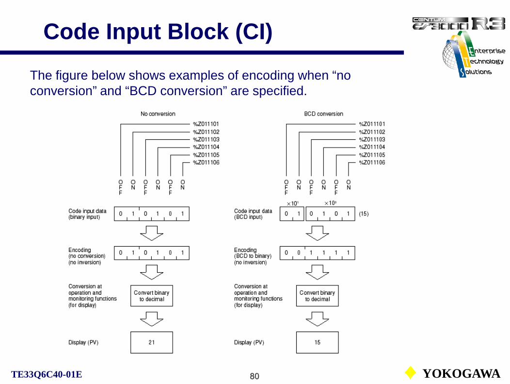
80 YOKOGAWATE33Q6C40-01E
Code Input Block (CI)
The figure below shows examples of encoding when “no conversion” and “BCD conversion” are specified.
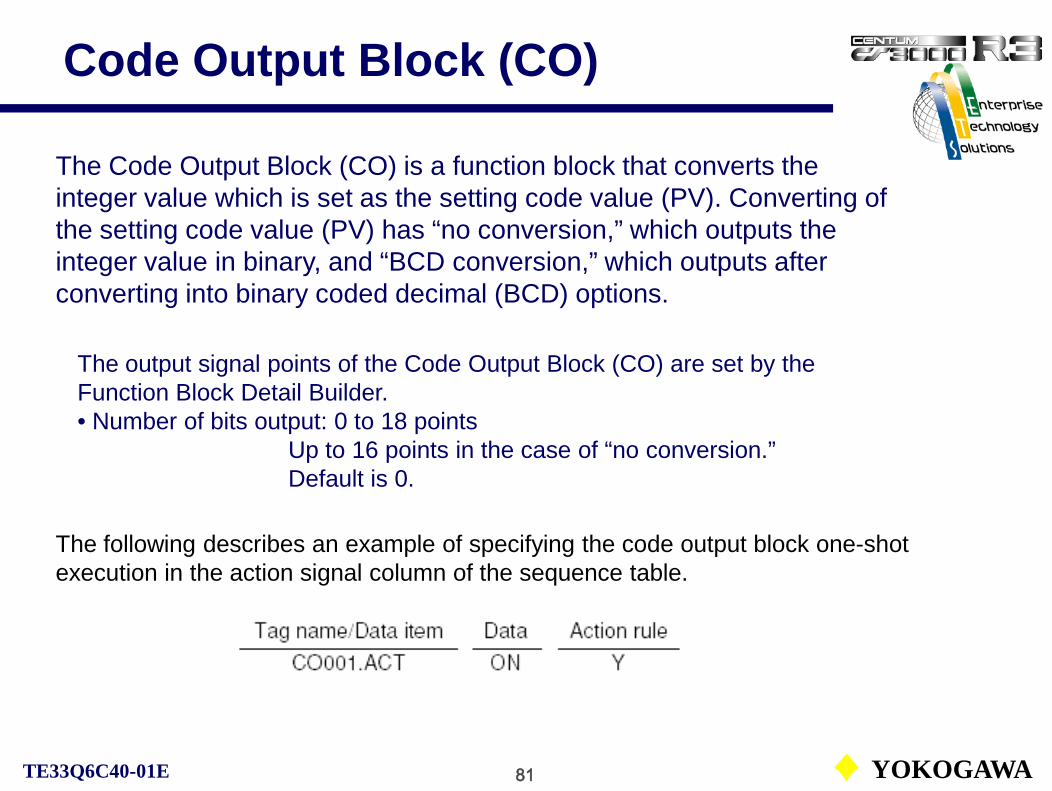
81 YOKOGAWATE33Q6C40-01E
Code Output Block (CO)
The Code Output Block (CO) is a function block that converts the integer value which is set as the setting code value (PV). Converting of the setting code value (PV) has “no conversion,” which outputs the integer value in binary, and “BCD conversion,” which outputs after converting into binary coded decimal (BCD) options.
The output signal points of the Code Output Block (CO) are set by the Function Block Detail Builder.• Number of bits output: 0 to 18 points
Up to 16 points in the case of “no conversion.”Default is 0.
The following describes an example of specifying the code output block one-shot execution in the action signal column of the sequence table.
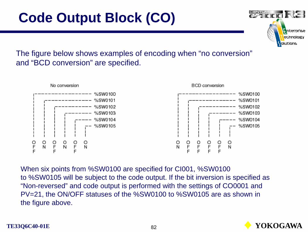
82 YOKOGAWATE33Q6C40-01E
Code Output Block (CO)
The figure below shows examples of encoding when “no conversion” and “BCD conversion” are specified.
When six points from %SW0100 are specified for CI001, %SW0100 to %SW0105 will be subject to the code output. If the bit inversion is specified as “Non-reversed” and code output is performed with the settings of CO0001 and PV=21, the ON/OFF statuses of the %SW0100 to %SW0105 are as shown in the figure above.

83 YOKOGAWATE33Q6C40-01E
Valve Monitor Block (VLVM)
The Valve Monitor Block (VLVM) is used to monitor whether the final control element (valve) is operating properly.
Action verification timers provide the grace time for the operation lag of the final control elements.
An example of connection of the valve monitoring block.
The representative abnormal state (PVR) is determined by the logical OR of individual valve abnormal statuses (PV01 to PV16).

1 YOKOGAWATE33Q6C40-01E
PART-E-Lab
Engineering CourseLaboratory Exercise

2 YOKOGAWATE33Q6C40-01E
Cascade Loop Creation
%Z011105 %Z011104
S’ry controller
Furnace
PID
FIC100
Fuel
OUT IN
Input module terminal number
Output moduleterminal number
%Z011103
Input moduleterminal number
P’ry controller
PID
TIC100
Product
OUT
IN
SET
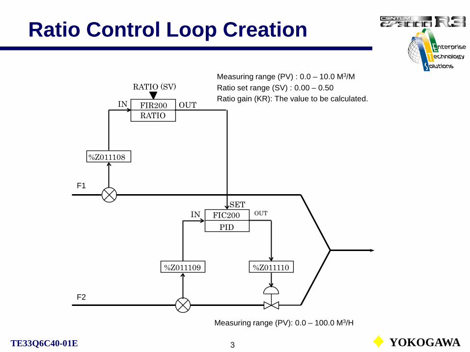
3 YOKOGAWATE33Q6C40-01E
Ratio Control Loop Creation
F1
FIR200
FIC200PID
RATIO
%Z011108
%Z011109 %Z011110
F2
SETIN
IN OUT
OUT
RATIO (SV)
Measuring range (PV): 0.0 – 100.0 M3/H
Measuring range (PV) : 0.0 – 10.0 M3/MRatio set range (SV) : 0.00 – 0.50Ratio gain (KR): The value to be calculated.

4 YOKOGAWATE33Q6C40-01E
Ratio Set Block (RATIO)
CALCn=KR • SVe • PVn+BIAS
CALCn: Current calculated output valuePVn: Current process variableSVe: Effective ratio setpoint valueKR: Ratio gainBIAS: Bias value

5 YOKOGAWATE33Q6C40-01E
Cascade Signal Distribution
TIC301PID
%Z011106
IN OUT
Measuring range (PV): 0.0 – 400.0 DEGC
Measuring range (PV) : 0.0 – 10.0 DEGC
SV range (SV): 0.0 – 100.0 %
%Z011111 %Z011112
TIC302PID
SETIN OUT TIC303
PID
%Z011113 %Z011114
SETIN OUT
FOUT300FOUT
SET
J01 J02
Measuring range (PV): 0.0 – 200.0 DEGC
MV range (MV2): 0.0 – 400.0 DEGCMV range (MV1): 0.0 – 200.0 DEGC
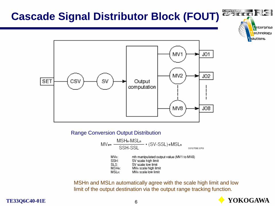
6 YOKOGAWATE33Q6C40-01E
Cascade Signal Distributor Block (FOUT)
Range Conversion Output Distribution
MSHn and MSLn automatically agree with the scale high limit and low limit of the output destination via the output range tracking function.

7 YOKOGAWATE33Q6C40-01E
Sequence Table Creation
ON
OFFOFF
3 s
ON
OFFOFF
Reset start
Count up (CTUP)
ON
OFFOFF
Start switch SW445
Switch SW446
Timer TM001
Switch SW447

8 YOKOGAWATE33Q6C40-01E
Sequence Table Creation (2)
Start switchSW450
Repeat 3 times(Counter)5 s Timer
settingSW451
SW452
SW453
SW454
SW455
SW456
Operator guide%OG0001

9 YOKOGAWATE33Q6C40-01E
Sequence Table Creation (3)Modification of the sequence table ST001.
[ST001-PB] Detection table Processing timing: TE
[ST001] Execution table Processing timing: TC
xx: Specify the step label using 2 or less alphanumeric characters.
Detection table action description
One shot action

10 YOKOGAWATE33Q6C40-01E
Sequence Table Creation (3)
Start detection
Start switchON
SW445.PV.O N
Y
Sequence running
Start switch : OFFSW445.PV.H : N
Start switch : OFFSW445.PV.H : N
Execution table starting step (A1) startsST001.SA.A1 : Y
Output op. guide “Operation miss!”
%OG0002.PV.NON : Y
ST001.MODE.AUT
Y
N
N
Start instruction detection[ST001-PB]
ST001.SA.A1 : YCondition of the A1 (Start) step in ST001 is unconditionally satisfied.Start operation is executed.

11 YOKOGAWATE33Q6C40-01E
Sequence Table Creation (3)
Stop detection
Stop switchON
SW444.PV.O N
Y
Sequence running
Stop switch : OFFSW444.PV.H : N
Stop switch : OFFSW444.PV.H : N
Execution table stop step (SP) startsST001.SA.SP : Y
Output op. guide “Operation miss!”
%OG0002.PV.NON : Y
ST001.MODE.AUTN
Y
N
Stop instruction detection
[ST001-PB]
ST001.SA.SP : YCondition of the SP (Stop) step in ST001 is unconditionally satisfied.Stop operation is executed.

12 YOKOGAWATE33Q6C40-01E
Calculation Function Creation
TI003CALCU-C
LI003PVI
TI003HPVI
TI003MPVI
TI003LPVI
40%
70%
Q03Q02
Q01
PV
IN IN IN IN
PVPVPV
IN
Levelindicator
Low leveltemperature
indicator
Medium leveltemperature
indicator
High leveltemperature
indicator
Reactor

13 YOKOGAWATE33Q6C40-01E
Calculation Program
Comment
output

14 YOKOGAWATE33Q6C40-01E
Logic Chart Creation (1)
Input ElementsInput1 Logic Elements Output Elements
Output1
SW301.PV.ON
SW302.PV.ON
SW303.PV.ON
SW304.PV.ON
SW305.PV.ON
SW304.PV.L
SW305.PV.L
R
S2
SRS2-ROR
AND
AND
OND
OND
1
2
Comments
Comments

15 YOKOGAWATE33Q6C40-01E
Logic Chart Creation (2-1)

16 YOKOGAWATE33Q6C40-01E
Logic Chart Creation (2-2)

17 YOKOGAWATE33Q6C40-01E
Logic Chart Creation (2-3)

18 YOKOGAWATE33Q6C40-01E
Graphic ExerciseStation Number HIS0124
(Left hand side, Odd No.PC)HIS0123
(Right hand side, Even No. PC)
Window name
TRAINOV-A TRAINOV-B
TRAINCG-A TRAINCG-B
TRAINGR-A TRAINGR-B
TRAINORGR-A TRAINORGR-B
Tag nameFBS101-A FBS101-B
LAG109-A LAG109-B

19 YOKOGAWATE33Q6C40-01E
Graphic Exercise

20 YOKOGAWATE33Q6C40-01E
Graphic Exercise

1 YOKOGAWATE33Q6C40-01E
Arithmetic Calculation and Logic Operation
CS1000/3000 Engineering Course Textbook
PART-F
Arithmetic Calculation and Logic Operation

2 YOKOGAWATE33Q6C40-01E
CS1000/3000 Engineering Course TextbookPART-F Arithmetic Calculation and Logic Operation
Reference: IM33S01B30-01EPART-D Function Block Details, D2 Arithmetic Calculation, Logic Operation
F1. Arithmetic Calculation, Logic Operation PositioningF2. Structure of Calculation BlocksF3. Types of Calculation BlocksF4. General Purpose Calculation Block
Arithmetic Calculation and Logic Operation
3 YOKOGAWATE33Q6C40-01E
Arithmetic Calculation, Logic Operation Positioning
CS1000/3000 Engineering Course Textbook
PART-F 1Arithmetic Calculation, Logic Operation Positioning

4 YOKOGAWATE33Q6C40-01E
The arithmetic calculation and logic operation function blocks perform general-purpose calculation processing, such as numerical calculation, analog calculation and logical calculation for the input signals to the block.
Calculation Block Positioning
FCS
Basic control Software I/O
I/O interfaces

5 YOKOGAWATE33Q6C40-01E
Structure of Calculation Blocks
CS1000/3000 Engineering Course Textbook
PART-F 2Structure of Calculation Blocks

6 YOKOGAWATE33Q6C40-01E
IN
SUB
Q01
RV
P01
CPV
Q07
OUT
J01
Jn
P08
RV1
RV7
CPV1
CPV3
Input processing
Output processing
Calculation processing
Structure of Calculation BlockThe calculation blocks receive analog signals (and status signals) as input values, and perform calculations according to the set parameters.
Receives a signal from the Input terminal and outputs a calculated input (RV).
Reads the calculated inputs (RV to RV7) and performs calculation to output the calculated outputs (CPV to CPV3).
Reads the calculated output (CPV) and outputs a calculation result to the destination of the output terminal as an output.

7 YOKOGAWATE33Q6C40-01E
Types of Calculation Blocks
CS1000/3000 Engineering Course Textbook
PART-F 3Types of Calculation Blocks

8 YOKOGAWATE33Q6C40-01E
Types of Calculation Blocks
General-purpose calculation blocksCALCU: General-purpose calculation blockCALCU-C: General purpose calculation block with string I/O
According to the data type and calculation capability, the calculation function blocks are classified into arithmetic calculation blocks, analog calculation blocks, general-purpose calculation blocks and calculation auxiliary blocks.
Arithmetic calculation blocksADD, MUL, DIV, AVEAnalog calculation blocksSQRT, LAG, DLAY, LDLAG, AVE-MLogic operation blocks (CS3000 only)AND, OR, NOT, EQ
Calculation auxiliary blocksSW-33, SW-91, DSET, ADL
See IM33S01B30-01E PART-D Function Block Details, D2 Arithmetic Calculation, Logic Operation. See also Supplements VIII. Calculation Function Blocks.

9 YOKOGAWATE33Q6C40-01E
Types of Calculation BlocksAn arithmetic block, typical analog calculation blocks and a calculation auxiliary block are shown below:
Addition block (ADD) First-order Lag block (LAG)
Lead / Lag block (LDLAG)Integration (INTEG)

10 YOKOGAWATE33Q6C40-01E
Types of Calculation Blocks
Three-pole three-position selector switch block (SW-33)Temperature and pressure
correction block (TPCFL)
Dead time block (DED) Moving average block (AVE-M)

11 YOKOGAWATE33Q6C40-01E
Creation of Calculation Block
General-purpose calculation block selection window
The user defined calculation program must be created.
Calculation program description window

12 YOKOGAWATE33Q6C40-01E
Calculation Block Application Example
FI100
ADD
Raw material line 1
FAVE101
AVE-M
IN
PV
FIC101
PIDIN
FAVE102
AVE-M
IN
FIC102
PIDIN
IN Q01
PVTotalized raw material
flow meter
Moving average
Moving average
Raw material line 2

13 YOKOGAWATE33Q6C40-01E
General Purpose Calculation Block
CS1000/3000 Engineering Course Textbook
PART-F 4General Purpose Calculation Block

14 YOKOGAWATE33Q6C40-01E
IN
Q01
RV
P01
CPV
User defined calculation processing
Q07
OUT
J01
J03
P08
RV1
RV7
CPV1
CPV3
Input processing
Output processing
SUB
General Purpose Calculation BlockThe general purpose calculation block is the function block that is used to define arbitral calculation algorithm.
For CALCU-C block, RV4 to RV7 and CPV2 to CPV3 are the character string data.
Calculation parameters:For CALCU-C block, P05 to P08 are the character string data.

15 YOKOGAWATE33Q6C40-01E
General Purpose Calculation Block
The general purpose arithmetic expressions are used in order to define the calculation algorithm of the general-purpose calculation blocks, CALCU and CALCU-C.
• Data items of an arbitrary function block can be referred to or setthrough the I/O terminal of the general-purpose calculation block.
• Arithmetic expressions which handle character strings such as messages and block modes can be described.
• Processing such as conditional jumps can be described by using control statements.
• Built-in functions which execute calculations for the temperature correction or pressure correction and so on can be used.
See Supplement VIII. Calculation Function Blocks.

16 YOKOGAWATE33Q6C40-01E
Arithmetic Expression Structure
An example of the structure of general-purpose arithmetic expressions is shown below:
Program* Beginning of arithmetic expressions.Integer I001, I002, I003Float F001, F002
TIC100.VN=FIC100.CPV*F001 ! Data set{SW100.SV.3}={TIC100.MODE.AUT} ! Operation controlTIC100.SV=25.0 ! Data set
* End of arithmetic expressions.End
Executable statements
Max. 20 lines
Comment Max. 250 lines
Allowable number of lines of executable statements is about 20 lines for the statement like A=A1+A2+A3+A4.
Declaration statements
Comment
See Supplement VIII. 2. General Purpose Arithmetic Expressions.

17 YOKOGAWATE33Q6C40-01E
Arithmetic Expression ExampleAn example of general-purpose expression:
Program* Beginning of arithmetic expressions. Integer I001, I002, I003Float F001, F002
TIC100.VN = FIC100.CPV*F001 ! Data settingTIC100.SV = 25.0
* End of arithmetic expressions.End
Identifiers: Character strings that represent variables and labels.Constants: Character strings that represent values themselves.
Local variables
I/O variables
A variable: Data that has a name and a data type. There are two types: Local variables and I/O variables.
An operator: Anything that designates an action to be performed.
OperatorConstant

18 YOKOGAWATE33Q6C40-01E
Control Statements
The control statement is a statement for controlling the execution order of arithmetic expressions.
There are four kinds as shown below:
• if statement: Condition testing
• switch statement: Multiple-branch processing
• goto statement: Unconditional jump
• exit statement: Jumps to the “end” statement unconditionally.
e.g. if ( A > B ) then C = D + E

19 YOKOGAWATE33Q6C40-01E
Program Example
* #define: The compiler control instruction for character string substitution.
A program that calculates tank temperature according to the liquid level of the tank is shown below:
*
output

20 YOKOGAWATE33Q6C40-01E
Sequence ConnectionArithmetic expressions can describe a sequential control same as a sequence table.
Program
{SW100.SV.3} = {TIC100.MODE.AUT}
End
An example of sequence connection expression:
* For easier maintenance, it is recommended that the arithmetic expression blocks should be used for calculations and substitutions of data, and the sequence table blocks should be used for operation controls.
I/O variables are sandwiched with ‘{‘ and ‘}’.
TIC100.MODE. AUT Y
SW100.SV. 3 Y
Description with ST-16.

1 YOKOGAWATE33Q6C40-01E
PART-F Lab. Exercise
Fundamental CourseLaboratory Exercise

2 YOKOGAWATE33Q6C40-01E
Laboratory Exercise
Reactor A Reactor B
Tag name e.g.
******-ATIC102-A
******-BTIC102-B
Overview window REACTORSREACT-A-OV
REACTORSREACT-B-OV
Control window REACT-A-CGREACT-A-CG2
REACT-B-CGREACT-B-CG2
Graphic window REACT-A-GR REACT-B-GR
Trend window TG0101TG0501
TG0111TG0511
Function keyCall REACT-A/B-GRCall REACT-A/B-OVCall REACT-A/B-CGCall REACT-A/B-CG2Call TG0101/0111Call TG0501/0511Call sequence table
1234567
17181920212223
Odd No. PC(HIS0124)
Even No. PC(HIS0123)
TCPJT is installed only in HIS0124.

3 YOKOGAWATE33Q6C40-01E
Laboratory Exercise

4 YOKOGAWATE33Q6C40-01E
Laboratory Exercise
Window call menu
Toolbox
Operation menu