Digitized Speech Transmission at VHF Using Existing FM Mobile Radios
Upload
khangminh22Category
view
6download
0
aerospace
Article
VHF Omnidirectional Range (VOR) Experimental Positioningfor Stratospheric Vehicles
Lorenzo Frezza 1, Paolo Marzioli 2,* , Fabio Santoni 1 and Fabrizio Piergentili 2
�����������������
Citation: Frezza, L.; Marzioli, P.;
Santoni, F.; Piergentili, F. VHF
Omnidirectional Range (VOR)
Experimental Positioning for
Stratospheric Vehicles. Aerospace 2021,
8, 263. https://doi.org/10.3390/
aerospace8090263
Academic Editor: Paolo Tortora
Received: 9 August 2021
Accepted: 11 September 2021
Published: 15 September 2021
Publisher’s Note: MDPI stays neutral
with regard to jurisdictional claims in
published maps and institutional affil-
iations.
Copyright: © 2021 by the authors.
Licensee MDPI, Basel, Switzerland.
This article is an open access article
distributed under the terms and
conditions of the Creative Commons
Attribution (CC BY) license (https://
creativecommons.org/licenses/by/
4.0/).
1 Department of Astronautical, Electric and Energy Engineering, Sapienza University of Rome, via Eudossiana18, 00184 Rome, Italy; [email protected] (L.F.); [email protected] (F.S.)
2 Department of Mechanical and Aerospace Engineering, Sapienza University of Rome, via Eudossiana 18,00184 Rome, Italy; [email protected]
* Correspondence: [email protected]
Abstract: The usage of aeronautical radio-frequency navigational aids can support the future strato-spheric aviation as back-up positioning systems. Although GNSS has been extensively redundant inthe last years of space operations, radio NavAids can still be supportive of navigation and trackingfor novel mission profiles. As an example, in 2016, VHF Omnidirectional Range (VOR) has beenproven to work well above its standard service volume limit on a stratospheric balloon flight with theSTRATONAV experiment. While VOR provides the “radial” measurement, i.e., the angle betweenthe Magnetic North and the line between the receiver and the transmitting ground station, theintersection of two or more radials at a time allows to perform ground track reconstruction for thevehicle to be tracked. This paper reports the results from the data re-processing from STRATONAV:the acquired radials have been intersected in order to achieve positioning. The radials interfacingmethod, the position calculation methodology, and the data acquisition strategies from STRATONAVare reported together with the data analysis results.
Keywords: stratosphere; positioning; Software Defined Radio; balloon; HAPS; VOR
1. Introduction
In the extremely complex scenario of the so-called New Space Economy, stratosphericmissions are obtaining an increasingly important role due to their effective capabilitiesof performing quasi-satellite tasks with lower development and installation costs, whencompared to orbital platforms [1]. To support the emerging mission concepts for strato-spheric payloads and for this transfer from space science to near-space missions [1,2], thefuture operations of stratospheric airships, High Altitude Platform Stations (HAPSs), andstratospheric vehicles will require an improvement of the navigation systems reliability forachieving more accurate navigation, station-keeping tasks, and positioning [3–8]. The uti-lization of a secondary navigation system, as back-up for than Global Navigation SatelliteSystem (GNSS), can introduce a further improvement to the navigation systems reliabilityand to the mission execution itself [9–11]. Aeronautical Navigational Aids (NavAids) cansupport these new concept mission profiles with an extension of their usual service volume.Passive NavAids, such as the VHF Omnidirectional Range (VOR, [12–14]), can supportthe missions by requiring only passive Radio-Frequency (RF) airborne hardware, thussimplifying the architecture of the additional navigation systems on-board the stratosphericplatforms. Although GNSS is currently already redundant (with several governmentalsystems active and operational) and aeronautical ground-based NavAids can be supportingsimilar missions only when overflying land, these NavAids can provide further support tostratospheric missions with an additional, independent navigation system.
These navigation systems are generally not allowing the users to directly achievepositioning, while the absolute position determination is in general possible throughfurther processing of the measurements. For example, the VOR system outputs the radial
Aerospace 2021, 8, 263. https://doi.org/10.3390/aerospace8090263 https://www.mdpi.com/journal/aerospace
Aerospace 2021, 8, 263 2 of 12
information, which equals the bearing angle of the line between the airborne receiver andthe VOR ground station with respect to the Magnetic North, without any information onthe actual position of the receiver [12]. If intersecting two radials, it is possible to calculatethe latitude and longitude of the receiver.
The STRATONAV experiment, developed at Sapienza University of Rome for theREXUS/BEXUS Programme (aiming at launching European student experiments on-boardstratospheric balloons and sounding rockets, [15]) has proven in 2016 the well-functioningof the VOR navigation system in stratospheric flight, while flying on a stratosphericballoon in Northern Sweden with an apogee of 32.2 km. The data analysis, describedin [16], confirmed that the reliability of such navigation system in stratospheric flight iscomparable to the current accuracy standards predicted by the International Civil AviationOrganization (ICAO, [12,17]) and they can satisfy the previous standard rates introducedin the first years of VOR operations.
After the accuracy determination analysis carried out with the data collected instratosphere, the STRATONAV data have been re-processed with the aim of achievingpositioning and ground-track estimation of the balloon trajectory by means of the VORmeasurements stand-alone. This paper reports the results from the VOR-based positioninganalysis carried out on the stratospheric balloon data from STRATONAV. The neededmaterials and methods, from an introduction on VOR to the data analysis principles anddata collection processes adopted on STRATONAV, will be described in Section 2, whilethe obtained results from the conducted analyses will be presented in Section 3, beforemoving to the conclusions in Section 4.
2. Materials and Methods2.1. VHF Omnidirectional Range (VOR)
VOR is a radio-navigational aid used for civil aviation since the late 1940s [12]. Thesystem is based on a network of transmitting ground stations and on receiving-onlyairborne receivers. The aim of VOR is to provide the user with the radial information,which is the angle between the Magnetic North and the line between the airborne receiverand the ground station. When VOR was used as primary navigation system for the civilaviation, the pilots could divide their optimal (orthodromic) route into straight segmentsbetween different VOR stations [18], maintaining the radial value constant to fly towardsthe destination. For achieving the radial calculation, the receiver carries out several signalprocessing tasks that are described as follows:
1. At signal reception, the receiver discriminates two different sub-modulated signals,namely, an AM sub-modulated reference sine wave and a FM sub-modulated direc-tional sine-wave;
2. The two sub-modulated sine waves are independently de-modulated and broughtback to base band, at 30 Hz;
3. The phase of the two signals is then compared and the obtained value is re-scaled asan angle (with values between 0 and 360 degrees);
4. The radial information is the obtained value.
As visible, VOR replicates in VHF the old concept of lighthouse navigation, wherethe omnidirectional signal substitutes the lighthouse white light and the directional sinewave substitutes the lighthouse rotating green light. The role of the receiver is to passivelydecode the signal and calculate the phase shift between the signals, which will be, as anexample, superposed when the radial is 0 degrees and opposed when the radial is 180degrees [17,18].
2.2. STRATONAV Experiment and Data Collection Processes
STRATONAV is a student stratospheric experiment developed in 2016 by the S5Lab(Sapienza Space Systems and Space Surveillance Laboratory) research team at SapienzaUniversity of Rome. The project aim was to verify the accuracy of VOR while flying instratosphere, since the Standard Service Volume (SSV) of VOR does not reach beyond 18 km
Aerospace 2021, 8, 263 3 of 12
of height above ground, while link budget calculations suggest that a broader utilization ispossible well above the predicted SSV end [19].
The experiment was selected in late 2015 for the ninth cycle of the REXUS/BEXUS Pro-gramme, managed by SNSA (Swedish National Space Agency), DLR (German AerospaceCenter), and ESA (European Space Agency) for providing launch opportunities on-boardsounding rockets and stratospheric balloons to European University students. The experi-ment was developed throughout 2016 at S5Lab by the student team, which was profitingfrom the lessons learned and the experience from previous space systems manufacturingprojects carried out at the laboratory [20–27]. The experiment was launched on-boardthe BEXUS 22 stratospheric balloon from the Esrange Space Center in Kiruna (Sweden),on 5 October 2016 at 13.35 UTC. The balloon overflew the Swedish and Finnish Laplandwith a ground track of approximately 240 km and a total flight time of approximately fourhours [16].
The experiment was equipped with two different Radio-Frequency receivers in orderto collect and detect VOR data:
• A COTS (Commercial Off The Shelf) portable VOR receiver, able to autonomouslyreceive and decode the signal and to show the calculated radial on the screen. Thisreceiver was modified by the team in order to be able to tune in the different VORfrequencies and to externally log the detected radials. This receiver will be referred as“COTS receiver” from now on;
• A Software Defined Radio (SDR) able to scan and record the frequencies of interest(from 108 MHz to 118 MHz). The recorded raw data was saved on a Solid State Drive(SSD) and post-processed after the experiment recovery after landing. This device willbe referred from now on as “SDR receiver” in the paper.
In order to be able to compare the collected data accuracy to real positioning data, acommercial GPS (Global Positioning System) receiver with native interconnectivity withthe selected On-Board Data Handling System [28] was included in the experiment box.After the flight, the GPS data retrieved by the experiment were compared and validatedwith the navigation and positioning data made available by the launch base team forthe balloon.
STRATONAV managed to acquire a large amount of data throughout the flight. TheVOR radials were proven to be within the previous ICAO standard accuracy rates for the99% of the collected samples. The experiment profited by a very high number of VORground stations installed in the flight area (i.e., Swedish and Finnish Lapland) [29–31].
Concerning the positioning data, the samples collected by the COTS receiver aremuch less than the ones collected by the SDR. This is justified by the data collectionprocesses: while the SDR scans the VHF band, recording all the VOR signals in the band,thus accessing at many VOR radials at a time, the COTS receiver can be tuned to a singlefrequency. The positioning samples, requiring two (or more) radials from different stations,can be collected only when the COTS receiver changes its tuning frequency between twoactive VOR stations.
2.3. VOR-Based Ground Track Determination
Two-dimensional positioning (determination of ground track) can be achieved whenintersecting two or more radial measurements acquired simultaneously. Latitude andlongitude of the balloon position are retrieved as follows.
Given ϕ1, λ1, θ1, namely, the latitude, longitude, and measured radial from the firststation, and ϕ2, λ2, θ2 from the second station, the positioning formula is obtained fromthe following formulas.
Aerospace 2021, 8, 263 4 of 12
As first step, it is necessary to calculate the angular distance between the two VORstation points, defined as δ12.
δ12 = 2· sin−1(
√sin2
(ϕ1 − ϕ2
2
)+ cos ϕ1· cos ϕ2· sin2
(λ1 − λ2
2
).
It is then necessary to compute the bearings between the two VOR stations positions.
ϑa = 2·acos(
sin ϕ2 − sin ϕ1· cos δ12
sin δ12· cos ϕ1
),ϑb = 2·acos
(sin ϕ1 − sin ϕ2· cos δ12
sin δ12· cos ϕ2
).
The angles θ1 and θ2 need to be reformatted as follows to compute the angulardistances to the intersection point within the trigonometric function domains.
If sin(λ1 − λ2) > 0 : θ12 = θa; θ21 = 2π − θb,Else : θ12 = 2π − θa; θ21 = θb.
All the angles among the three points (first and second VOR station, intersectionpoints), are then computed as follows. The subscript indicates the angle vertex, where 1and 2 are the VOR stations and 3 is the intersection point.
α1 = ϑ1 − θ12,α2 = ϑ21 − θ2,α3 = cos−1(− cos α1· cos α2 + sin α1· sin α2· cos δ12).
The angular distance between the first VOR station and the intersection point isthen computed.
δ13 = tan−1(sin δ12· sin α1· sin α2· cos α2 + cos α1· cos α3).
It is then possible to compute the latitude and longitude of the intersection pointas follows.
ϕ3 = sin−1(sin ϕ1· cos δ13 + cos ϕ1· cos ϑ1· sin δ13),
λ3 = λ1 + tan−1(
sin θ1· sin δ13· cos ϕ1
cos δ13 − sin ϕ1· sin ϕ3
).
Different optimizations have been performed for position computation on the COTSreceiver and SDR.
The following paragraphs present the results of the positioning test for the tworeceivers. A final summary is provided in the final sub-section of this paragraph.
3. Results
The results from the data post-processing will be divided in two subparagraphs: thefirst paragraph reports the obtained positioning data from the COTS receiver, while thesecond sub-paragraph will report the data analysis results from the SDR data.
3.1. COTS Receiver Data
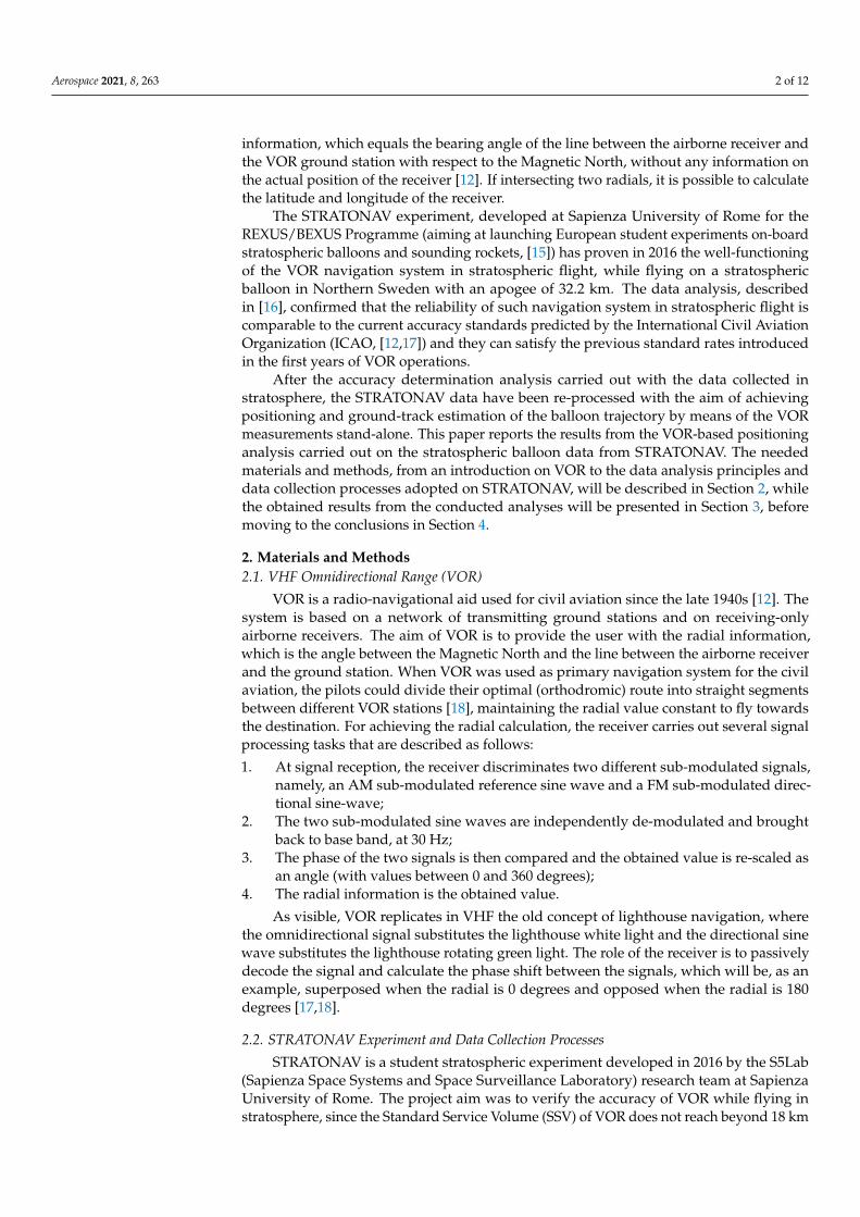
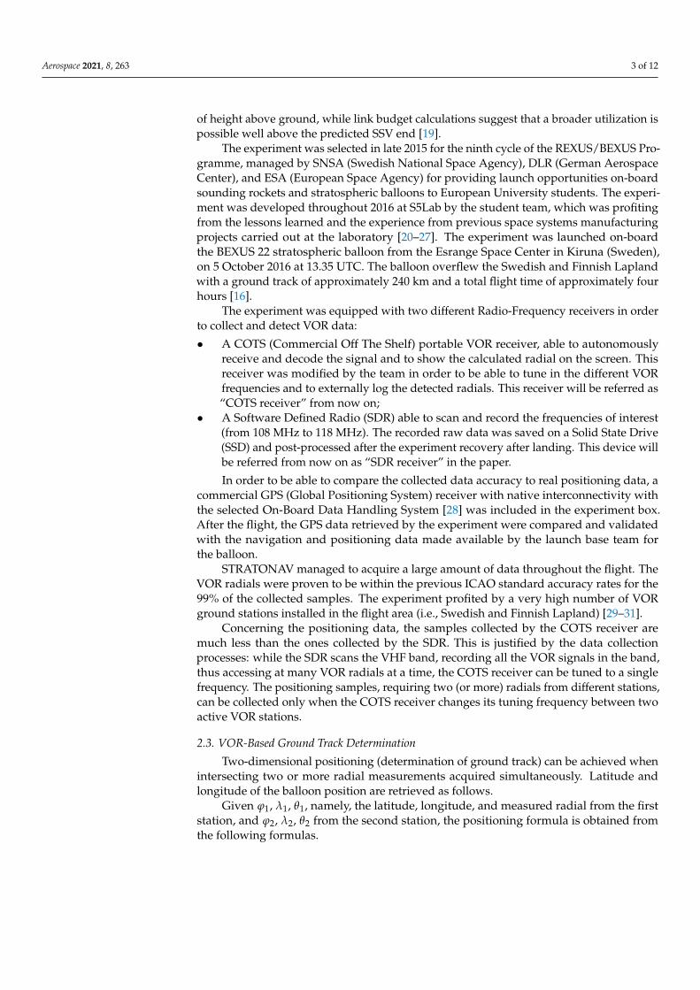
The comparison between the GPS ground track and the generated coordinates isdisplayed in Figure 1. A plot of the error (i.e., the distance between the GPS data andthe COTS radio VOR-based position estimate, in km) is presented in Figure 2, while avisualization of the ground track reconstruction in Google Earth is displayed in Figure 3.
Aerospace 2021, 8, 263 5 of 12Aerospace 2021, 8, x FOR PEER REVIEW 5 of 13
Figure 1. Comparison between GPS and VOR-based balloon ground track.
Figure 2. Error on the ground track determination through the COTS receiver data.
Figure 1. Comparison between GPS and VOR-based balloon ground track.
Aerospace 2021, 8, x FOR PEER REVIEW 5 of 13
Figure 1. Comparison between GPS and VOR-based balloon ground track.
Figure 2. Error on the ground track determination through the COTS receiver data. Figure 2. Error on the ground track determination through the COTS receiver data.
Aerospace 2021, 8, 263 6 of 12Aerospace 2021, 8, x FOR PEER REVIEW 6 of 13
(A)
(B)
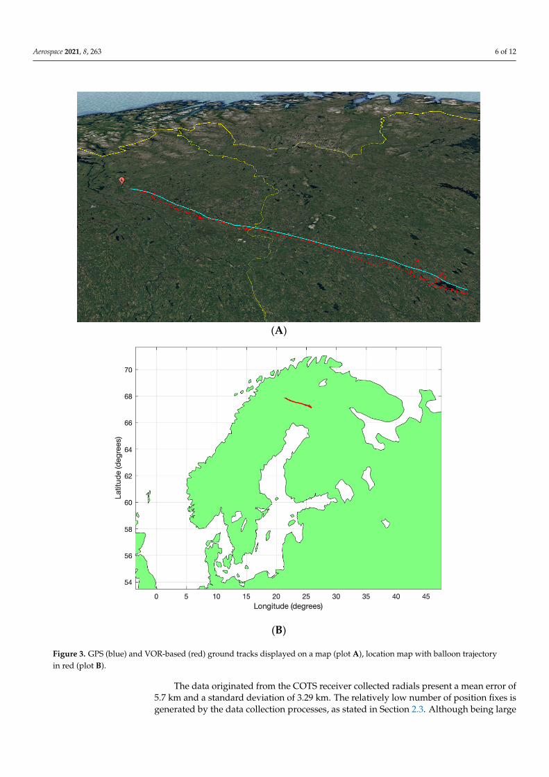
Figure 3. GPS (blue) and VOR-based (red) ground tracks displayed on a map (plot A), location map with balloon trajectory in red (plot B).
The data originated from the COTS receiver collected radials present a mean error of 5.7 km and a standard deviation of 3.29 km. The relatively low number of position fixes is generated by the data collection processes, as stated in Section 2.3. Although being large and much larger than an average GNSS error, a similar error can be considered compatible with a back-up positioning system. Optimizations can be implemented on the system if considering filters and trajectory and weather prediction models, e.g., an Extended Kalman Filter (EKF).
3.2. SDR Data Positioning The SDR data offered several advantages compared to the COTS receiver:
Increased sample rate of the VOR data; Concurrent reception of more than one station;
Figure 3. GPS (blue) and VOR-based (red) ground tracks displayed on a map (plot A), location map with balloon trajectoryin red (plot B).
The data originated from the COTS receiver collected radials present a mean error of5.7 km and a standard deviation of 3.29 km. The relatively low number of position fixes isgenerated by the data collection processes, as stated in Section 2.3. Although being large
Aerospace 2021, 8, 263 7 of 12
and much larger than an average GNSS error, a similar error can be considered compatiblewith a back-up positioning system. Optimizations can be implemented on the system ifconsidering filters and trajectory and weather prediction models, e.g., an Extended KalmanFilter (EKF).
3.2. SDR Data Positioning
The SDR data offered several advantages compared to the COTS receiver:
• Increased sample rate of the VOR data;• Concurrent reception of more than one station;• Tunable receiver settings.
These advantages proved decisive for the position estimation–more samples allowfor them to be filtered via an average, up to an arbitrarily high precision. The reception ofmultiple station at the same time on the other hand made it possible to compare the radialreading from different stations at the exact same time, greatly increasing the accuracy.
Contrary to the COTS receiver, it was necessary to demodulate the raw signal duringthe analysis, but this allowed for the fine tuning of the receiver settings and temperatureshift compensation of the local oscillator.
When more than two stations are received, more than one interception point is identi-fied when the radials are combined. It is therefore necessary to combine the informationfrom the different interception points in order to get the position estimation.
It is important to point out how the arrangement of the radials greatly influences theprecision of the position measurement: two orthogonal radials produce the most precisemeasurement, and the precision increases as the distance to the receivers reduces. On theother hand, two parallel radials provide no usable position at all.
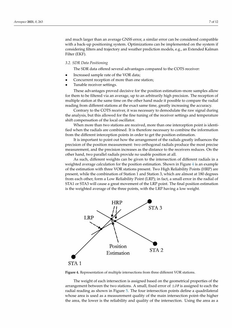
As such, different weights can be given to the intersection of different radials in aweighted average calculation for the position estimation. Shown in Figure 4 is an exampleof the estimation with three VOR stations present. Two High Reliability Points (HRP) arepresent, while the combination of Station 1 and Station 3, which are almost at 180 degreesfrom each other, form a Low Reliability Point (LRP); in fact, a small error in the radial ofSTA1 or STA3 will cause a great movement of the LRP point. The final position estimationis the weighted average of the three points, with the LRP having a low weight.
Aerospace 2021, 8, x FOR PEER REVIEW 7 of 13
Tunable receiver settings. These advantages proved decisive for the position estimation–more samples allow
for them to be filtered via an average, up to an arbitrarily high precision. The reception of multiple station at the same time on the other hand made it possible to compare the radial reading from different stations at the exact same time, greatly increasing the accuracy.
Contrary to the COTS receiver, it was necessary to demodulate the raw signal during the analysis, but this allowed for the fine tuning of the receiver settings and temperature shift compensation of the local oscillator.
When more than two stations are received, more than one interception point is identified when the radials are combined. It is therefore necessary to combine the information from the different interception points in order to get the position estimation.
It is important to point out how the arrangement of the radials greatly influences the precision of the position measurement: two orthogonal radials produce the most precise measurement, and the precision increases as the distance to the receivers reduces. On the other hand, two parallel radials provide no usable position at all.
As such, different weights can be given to the intersection of different radials in a weighted average calculation for the position estimation. Shown in Figure 4 is an example of the estimation with three VOR stations present. Two High Reliability Points (HRP) are present, while the combination of Station 1 and Station 3, which are almost at 180 degrees from each other, form a Low Reliability Point (LRP); in fact, a small error in the radial of STA1 or STA3 will cause a great movement of the LRP point. The final position estimation is the weighted average of the three points, with the LRP having a low weight.
Figure 4. Representation of multiple intersections from three different VOR stations.
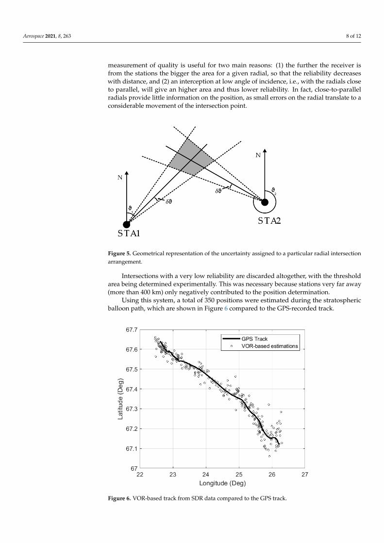
The weight of each intersection is assigned based on the geometrical properties of the arrangement between the two stations. A small, fixed error of ±훿휗 is assigned to each the radial reading as shown in Figure 5. The four intersection points define a quadrilateral whose area is used as a measurement quality of the main intersection point–the higher the area, the lower is the reliability and quality of the intersection. Using the area as a measurement of quality is useful for two main reasons: (1) the further the receiver is from the stations the bigger the area for a given radial, so that the reliability decreases with distance, and (2) an interception at low angle of incidence, i.e., with the radials close to parallel, will give an higher area and thus lower reliability. In fact, close-to-parallel radials provide little information on the position, as small errors on the radial translate to a considerable movement of the intersection point.
Figure 4. Representation of multiple intersections from three different VOR stations.
The weight of each intersection is assigned based on the geometrical properties of thearrangement between the two stations. A small, fixed error of ±δϑ is assigned to each theradial reading as shown in Figure 5. The four intersection points define a quadrilateralwhose area is used as a measurement quality of the main intersection point–the higherthe area, the lower is the reliability and quality of the intersection. Using the area as a
Aerospace 2021, 8, 263 8 of 12
measurement of quality is useful for two main reasons: (1) the further the receiver isfrom the stations the bigger the area for a given radial, so that the reliability decreaseswith distance, and (2) an interception at low angle of incidence, i.e., with the radials closeto parallel, will give an higher area and thus lower reliability. In fact, close-to-parallelradials provide little information on the position, as small errors on the radial translate to aconsiderable movement of the intersection point.
Aerospace 2021, 8, x FOR PEER REVIEW 8 of 13
Figure 5. Geometrical representation of the uncertainty assigned to a particular radial intersection arrangement.
Intersections with a very low reliability are discarded altogether, with the threshold area being determined experimentally. This was necessary because stations very far away (more than 400 km) only negatively contributed to the position determination.
Using this system, a total of 350 positions were estimated during the stratospheric balloon path, which are shown in Figure 6 compared to the GPS-recorded track.
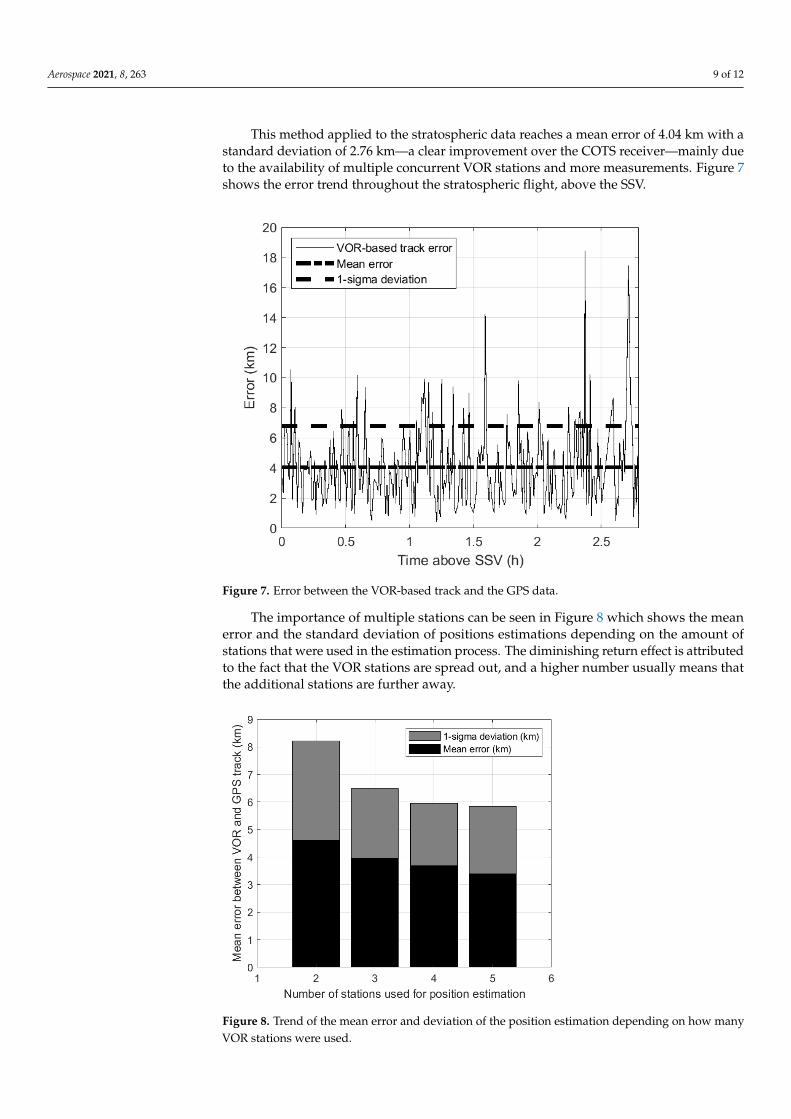
Figure 6. VOR-based track from SDR data compared to the GPS track.
This method applied to the stratospheric data reaches a mean error of 4.04 km with a standard deviation of 2.76 km—a clear improvement over the COTS receiver—mainly due to the availability of multiple concurrent VOR stations and more measurements. Figure 7 shows the error trend throughout the stratospheric flight, above the SSV.
Figure 5. Geometrical representation of the uncertainty assigned to a particular radial intersectionarrangement.
Intersections with a very low reliability are discarded altogether, with the thresholdarea being determined experimentally. This was necessary because stations very far away(more than 400 km) only negatively contributed to the position determination.
Using this system, a total of 350 positions were estimated during the stratosphericballoon path, which are shown in Figure 6 compared to the GPS-recorded track.
Aerospace 2021, 8, x FOR PEER REVIEW 8 of 13
Figure 5. Geometrical representation of the uncertainty assigned to a particular radial intersection arrangement.
Intersections with a very low reliability are discarded altogether, with the threshold area being determined experimentally. This was necessary because stations very far away (more than 400 km) only negatively contributed to the position determination.
Using this system, a total of 350 positions were estimated during the stratospheric balloon path, which are shown in Figure 6 compared to the GPS-recorded track.
Figure 6. VOR-based track from SDR data compared to the GPS track.
This method applied to the stratospheric data reaches a mean error of 4.04 km with a standard deviation of 2.76 km—a clear improvement over the COTS receiver—mainly due to the availability of multiple concurrent VOR stations and more measurements. Figure 7 shows the error trend throughout the stratospheric flight, above the SSV.
Figure 6. VOR-based track from SDR data compared to the GPS track.
Aerospace 2021, 8, 263 9 of 12
This method applied to the stratospheric data reaches a mean error of 4.04 km with astandard deviation of 2.76 km—a clear improvement over the COTS receiver—mainly dueto the availability of multiple concurrent VOR stations and more measurements. Figure 7shows the error trend throughout the stratospheric flight, above the SSV.
Aerospace 2021, 8, x FOR PEER REVIEW 9 of 13
Figure 7. Error between the VOR-based track and the GPS data.
The importance of multiple stations can be seen in Figure 8 which shows the mean error and the standard deviation of positions estimations depending on the amount of stations that were used in the estimation process. The diminishing return effect is attributed to the fact that the VOR stations are spread out, and a higher number usually means that the additional stations are further away.
Figure 8. Trend of the mean error and deviation of the position estimation depending on how many VOR stations were used.
Figure 7. Error between the VOR-based track and the GPS data.
The importance of multiple stations can be seen in Figure 8 which shows the meanerror and the standard deviation of positions estimations depending on the amount ofstations that were used in the estimation process. The diminishing return effect is attributedto the fact that the VOR stations are spread out, and a higher number usually means thatthe additional stations are further away.
Aerospace 2021, 8, x FOR PEER REVIEW 9 of 13
Figure 7. Error between the VOR-based track and the GPS data.
The importance of multiple stations can be seen in Figure 8 which shows the mean error and the standard deviation of positions estimations depending on the amount of stations that were used in the estimation process. The diminishing return effect is attributed to the fact that the VOR stations are spread out, and a higher number usually means that the additional stations are further away.
Figure 8. Trend of the mean error and deviation of the position estimation depending on how many VOR stations were used. Figure 8. Trend of the mean error and deviation of the position estimation depending on how manyVOR stations were used.
Aerospace 2021, 8, 263 10 of 12
4. Discussion
The results from the conducted analysis highlight how VOR-based positioning can beadopted in stratospheric flight to support the GNSS receivers, thus improving the reliabilityof the on-board navigation and station keeping system for stratospheric missions.
Between the two analyzed sensors, the SDR has been demonstrated as capable ofreaching higher accuracy and precision values. The lower performances of the COTSreceivers are mainly determined by the data acquisition strategy, forcing to receive radialsfrom one only station at a time, thus allowing to achieve positioning when switchingfrequencies from one station to the other. On the other hand, the SDR spectrum recordingallows to acquire many VOR radial simultaneously, permitting to perform an optimizationamong the collected radials to achieve more accurate positioning. Although these anal-yses were performed after the stratospheric flight, an automatic, real-time, data analysisfrom SDR data can be achieved through airborne computing units and low cost SDRs.Software Defined Radio architectures for stratospheric or even suborbital tracking offerextremely interesting perspectives in terms of ease of implementation, flexibility, and lowcosts. After STRATONAV, other experiments have been conceived and developed at S5Labto perform SDR-based tracking of stratospheric balloons. For example, a further experi-ment developed by S5Lab for the REXUS/BEXUS Programme, named TARDIS (Trackingand Attitude Radio-based Determination In Stratosphere [32]), was aimed at real-timedetermination of the position and attitude of the BEXUS gondola while in stratosphericflight through SDRs. New concept experiments on innovative tracking systems are the aimof STRAINS (Stratospheric Tracking Innovative Systems, [33]), a new experiment aimedat demonstrating large baseline Time Difference of Arrival (TDOA) for stratospheric andsuborbital vehicles, in the perspective of a future implementation for satellite tracking andSpace Traffic Management. For the adopted technologies and for their implementationon-board the flight unit, STRATONAV can be considered a precursor of the mentioned newprojects that have profited from the lessons learned from this successful experimentation.As for the future applicability of such experimental units, SDRs can be easily implementedon all stratospheric vehicles for real-time navigation purposes: an independent unit withbatteries, computing unit and RF hardware can easily present a mass below 0.5 kg andvery limited volume occupation (even less than 50 × 100 × 100 mm, as demonstrated forsmall satellites implementing the same technologies [34]).
If implementing VOR or VOR-based signal processing techniques as secondary navi-gation method, it shall be remarked how VOR can be available only above land and it findsno applications when overflying the ocean. Although this limitation can anyway fit withseveral mission profiles (e.g., temporary probing of populated areas or telecommunicationlinks for areas caught by natural disasters), the service cannot be assured worldwide as forthe GNSS. Furthermore, the implementation costs of SDR technology for exploitation ofradio-navigation systems have a comparable cost to low-cost GNSS receivers on redundantconstellations. Finally, some of the NavAids, including VOR, are progressively undergoingdiscontinuation by some national civil aviation authorities, which can limit the futureapplications of the investigated system [35], although proposing a promising secondarypositioning method.
5. Conclusions
The data from the STRATONAV Experiment, launched in 2016 on a BEXUS strato-spheric balloon from the Esrange Space Center in Kiruna, Sweden, have been reprocessedin order to achieve positioning through the intersection of multiple VOR radials. Theexperiment data collection was made possible through two separate receivers: a commer-cial receiver able to decode a radial at a time and a SDR recording the entire VOR bandspectrum, therefore able to acquire all the VOR signals simultaneously.
The positioning accuracy reached with the re-processing of the VOR data amounts5.7 km of mean error and 3.29 km of standard deviation, which can be profiting from alimited amount of data due to the single radial data collection strategy, and 4.04 km and
Aerospace 2021, 8, 263 11 of 12
2.76 km of standard deviation for the SDR. The results are acceptable to consider the systema potential, low-cost back-up for high altitude GNSS receivers on stratospheric airships.From the STRATONAV results, further experiments have been started for stratosphericballoons: TARDIS had the aim of achieving real-time positioning and attitude determi-nation through SDRs, while STRAINS uses the same technology for testing long baselineTDOA with stratospheric balloons in the perspective of future suborbital and satelliteexperimentation.
Author Contributions: Conceptualization, P.M.; methodology, P.M. and L.F.; software, P.M. and L.F.;investigation, P.M. and L.F.; writing—original draft preparation, P.M. and L.F.; writing—review andediting, P.M.; visualization, L.F.; supervision, F.P. and F.S. All authors have read and agreed to thepublished version of the manuscript.
Funding: The STRATONAV experiment development received funding and support by the followingcompanies: Eggcelerate, Mediasoft, MEGATRON Sensors, and Italian Amateur Radio Association(ARI)–Rome.
Institutional Review Board Statement: Not applicable.
Informed Consent Statement: Not applicable.
Data Availability Statement: Data sharing not applicable.
Acknowledgments: STRATONAV project was part of the REXUS/BEXUS Programme. The REXUS/BEXUS programme is realized under a bilateral Agency Agreement between the German AerospaceCenter (DLR) and the Swedish National Space Agency (SNSA). The Swedish share of the payloadhas been made available to students from other European countries through the collaboration withthe European Space Agency (ESA). Experts from DLR, SSC, ZARM and ESA provide technicalsupport to the student teams throughout the project. EuroLaunch, the cooperation between theEsrange Space Center of SSC and the Mobile Rocket Base (MORABA) of DLR, is responsible for thecampaign management and operations of the launch vehicles. The publication of this manuscriptis provided by the Italian Space Agency in the framework of the Accordo Attuativo ASI 2020-30-HH.0—IKUNS3-SIMBA for the future implementation of the developed radio-frequency technologieson-board nano-satellites.
Conflicts of Interest: The authors declare no conflict of interest.
References1. Gonzalo, J.; López, D.; Domínguez, D.; García, A.; Escapa, A. On the Capabilities and Limitations of High Altitude Pseudo-
Satellites. Prog. Aerosp. Sci. 2018, 98, 37–56. [CrossRef]2. Santoro, F.; Del Bianco, A.; Viola, N.; Fusaro, R.; Albino, V.; Binetti, M.; Marzioli, P. Spaceport and Ground Segment Assessment for
Enabling Operations of Suborbital Transportation Systems in the Italian Territory. Acta Astronaut. 2018, 152, 396–407. [CrossRef]3. van Wynsberghe, E.; Turak, A. Station-Keeping of a High-Altitude Balloon with Electric Propulsion and Wireless Power
Transmission: A Concept Study. Acta Astronaut. 2016, 128, 616–627. [CrossRef]4. Konefal, T.; Tozer, T.C.; Thornton, J.; Grace, D.; Spillard, C. Broadband Communications from a High-Altitude Platform: The
European HeliNet Programme. Electron. Commun. Eng. J. 2001, 13, 138–144. [CrossRef]5. Tozer, T.C.; Grace, D. High-Altitude Platforms for Wireless Communications. Electron. Commun. Eng. J. 2001, 13, 127–137.
[CrossRef]6. Alam, M.I.; Pant, R.S. Multi-Objective Multidisciplinary Design Analyses and Optimization of High Altitude Airships. Aerosp.
Sci. Technol. 2018, 78, 248–259. [CrossRef]7. Du, H.; Lv, M.; Zhang, L.; Zhu, W.; Wu, Y.; Li, J. Energy Management Strategy Design and Station-Keeping Strategy Optimization
for High Altitude Balloon with Altitude Control System. Aerosp. Sci. Technol. 2019, 93, 105342. [CrossRef]8. Aragón-Zavala, A.; Cuevas-Ruiz, J.L.; Delgado-Penín, J.A. High-Altitude Platforms for Wireless Communications; Wiley: Chichester,
UK, 2008; ISBN 978-0-470-51061-2.9. Gao, Z.; Ge, M.; Li, Y.; Shen, W.; Zhang, H.; Schuh, H. Railway Irregularity Measuring Using Rauch–Tung–Striebel Smoothed
Multi-Sensors Fusion System: Quad-GNSS PPP, IMU, Odometer, and Track Gauge. GPS Solut. 2018, 22, 36. [CrossRef]10. Liu, W.; Shi, X.; Zhu, F.; Tao, X.; Wang, F. Quality Analysis of Multi-GNSS Raw Observations and a Velocity-Aided Positioning
Approach Based on Smartphones. Adv. Space Res. 2019, 63, 2358–2377. [CrossRef]11. Specht, C.; Weintrit, A.; Specht, M. A History of Maritime Radio-Navigation Positioning Systems Used in Poland. J. Navig. 2016,
69, 468–480. [CrossRef]
Aerospace 2021, 8, 263 12 of 12
12. International Civil Aviation Organization (ICAO). Annex 10—Aeronautical Telecommunications; ICAO: Montréal, QC, Canada, 2001;Volume I.
13. International Civil Aviation Organization (ICAO). Navigation Roadmap; ICAO Workshop on PBN Airspace Redesign and GNSSImplementation Supporting PBN; ICAO: Montréal, QC, Canada, 2012.
14. Anderson, W.G. The Accuracy of the VHF Omni-Range System of Aircraft Navigation; A Statistical Study. IRE Trans. Aeronaut.Navig. Electron. 1955, ANE-2, 25–37. [CrossRef]
15. REXUS. BEXUS Programme Official Website: BEXUS Projects. Available online: http://rexusbexus.net/bexus/ (accessed on 8August 2021).
16. Marzioli, P.; Frezza, L.; Curianò, F.; Pellegrino, A.; Gianfermo, A.; Angeletti, F.; Arena, L.; Cardona, T.; Valdatta, M.;Santoni, F.; et al. Experimental Validation of VOR (VHF Omni Range) Navigation System for Stratospheric Flight. Acta Astronaut.2021, 178, 423–431. [CrossRef]
17. European Organization for Civil Aviation Electronics. EuroCAE ED-52: Minimum Operational Performance Specification (MPS)for Ground Conventional and Doppler Very High Frequency Omni Range (CVOR and DVOR) Equipment; EuroCAE: Saint-Denis,France, 1984.
18. Moir, I.; Seabridge, A.G. Aircraft Systems: Mechanical, Electrical and Avionics Subsystems Integration, 3rd ed.; John Wiley & Sons Inc.:Chichester, UK; Hoboken, NJ, USA, 2008; ISBN 978-0-470-05996-8.
19. Marzioli, P.; Curianò, F.; Pellegrino, A.; Angeletti, F.; Frezza, L.; Gianfermo, A.; Valdatta, M.; Arena, L.; Cardona, T. Testing VORPerformances in the Stratosphere: The STRATONAV Experiment (Paper Code: IAC-16,B2,2,7,X34462). In Proceedings of the 68thInternational Astronautical Congress, Guadalajara, Mexico, 26–30 September 2016.
20. Pastore, R.; Delfini, A.; Micheli, D.; Vricella, A.; Marchetti, M.; Santoni, F.; Piergentili, F. Carbon Foam Electromagnetic Mm-WaveAbsorption in Reverberation Chamber. Carbon 2019, 144, 63–71. [CrossRef]
21. Piattoni, J.; Ceruti, A.; Piergentili, F. Automated Image Analysis for Space Debris Identification and Astrometric Measurements.Acta Astronaut. 2014, 103, 176–184. [CrossRef]
22. Candini, G.P.; Piergentili, F.; Santoni, F. Designing, Manufacturing, and Testing a Self-Contained and Autonomous NanospacecraftAttitude Control System. J. Aerosp. Eng. 2014, 27, 04014033. [CrossRef]
23. Piergentili, F.; Candini, G.P.; Zannoni, M. Design, Manufacturing, and Test of a Real-Time, Three-Axis Magnetic Field Simulator.IEEE Trans. Aerosp. Electron. Syst. 2011, 47, 1369–1379. [CrossRef]
24. Santoni, F.; Piergentili, F.; Graziani, F. The UNISAT Program: Lessons Learned and Achieved Results. Acta Astronaut. 2009, 65,54–60. [CrossRef]
25. Santoni, F.; Piergentili, F.; Bulgarelli, F.; Graziani, F. UNISAT-3 Power System. In Proceedings of the European Space Agency,(Special Publication) ESA SP, Stresa, Italy, 9 May 2015; pp. 395–400.
26. Marzioli, P.; Gugliermetti, L.; Santoni, F.; Delfini, A.; Piergentili, F.; Nardi, L.; Metelli, G.; Benvenuto, E.; Massa, S.; Bennici, E.CultCube: Experiments in Autonomous in-Orbit Cultivation on-Board a 12-Units CubeSat Platform. Life Sci. Space Res. 2020, 25,42–52. [CrossRef]
27. Santoni, F.; Gugliermetti, L.; Piras, G.; De Pascale, S.; Pannico, A.; Piergentili, F.; Marzioli, P.; Frezza, L.; Amadio, D.;Gianfermo, A.; et al. GreenCube: Microgreens Cultivation and Growth Monitoring on-Board a 3U CubeSat. In Proceedings of the2020 IEEE 7th International Workshop on Metrology for AeroSpace (MetroAeroSpace), Pisa, Italy, 22–24 June 2020; pp. 130–135.
28. ADAFRUIT Adafruit GPS Breakout Datasheet. Available online: https://cdn-learn.adafruit.com/downloads/pdf/adafruit-ultimate-gps.pdf (accessed on 31 August 2021).
29. Finavia Finland Aeronautical Information Publication (AIP). Available online: https://ais.fi/C-en (accessed on 8 August 2021).30. LFV—Swedish National Entity for Flight Assistance Aeronautical Information Publications (AIPs) for Instrumental Flight Rules
(IFR) in Sweden. Available online: https://www.aro.lfv.se/ (accessed on 8 August 2021).31. AVINOR—Norway National Entity for Flight Assistance Aeronautical Information Publications (AIPs) for Instrumental Flight
Rules (IFR) in Norway. Available online: https://www.ippc.no/norway_aip/current/main_en.html (accessed on 8 August 2021).32. di Palo, L.; Bandini, V.; Bedetti, E.; Broggi, G.; Collettini, L.; Celesti, P.; Ienno, D.D.; Garofalo, R.; Iovanna, F.; Mattei, G.; et al.
Stratospheric Balloon Attitude and Position Determination System Based on the VHF Omnidirectional Range Signal Processing:TARDIS Experiment. In Proceedings of the 2019 IEEE 5th International Workshop on Metrology for AeroSpace (MetroAeroSpace),Rome, Italy, 20–22 June 2019; pp. 607–612.
33. di Palo, L.; Garofalo, R.; Bedetti, E.; Celesti, P.; Iovanna, F.; Frezza, L.; Marzioli, P.; Piergentili, F.; Volpe, A.; Curianò, F.; et al. TimeDifference of Arrival for Stratospheric Balloon Tracking: Design and Development of the STRAINS Experiment. In Proceedings ofthe 2020 IEEE 7th International Workshop on Metrology for AeroSpace (MetroAeroSpace), Pisa, Italy, 22–24 June 2020; pp. 362–366.
34. Frezza, L.; Marzioli, P.; Curianò, F.; Gugliermetti, L.; Amadio, D.; Pirrotta, S.; Kimani, J.N.; Mwita, P.; Mwaniki, C.; Santoni, F. From1KUNS-PF to WildTrackCube-SIMBA: Strengthening the Cooperation between Italy and Kenya in Nano-Satellite Manufacturingand Operations. In Proceedings of the 71st International Astronautical Congress—The Cyberspace Edition, Held Virtually,12–14 October 2020.
35. Ken Ward Discontinuation of VOR Service, April 2012. Available online: https://www.faa.gov/air_traffic/flight_info/aeronav/acf/media/Presentations/12-01_Discon-of-VOR-update.pdf (accessed on 14 September 2021).
Copyright © 2022 FDOKUMEN