Obstacles Avoidance for Car-like Robots Integration and Experimentation on Two Robots
Upload
independentCategory
view
1download
0
Journal of Intelligent and Robotic Systems22: 315–330, 1998.© 1998Kluwer Academic Publishers. Printed in the Netherlands.
315
Feedback Control of an OmnidirectionalAutonomous Platform for Mobile Service Robots
KEIGO WATANABE and YAMATO SHIRAISHIDepartment of Mechanical Engineering, Saga University, 1-Honjomachi, Saga 840, Japan
SPYROS G. TZAFESTASComputer Science Division, National Technical University of Athens, Zografou Campus,15773 Athens, Greece
JUN TANGDepartment of Mechanical Engineering, Yamaguchi University, 2557 Tokiwadai, Ube 755, Japan
TOSHIO FUKUDADepartment of Micro Systems Engineering, Nagoya University, Furo-cho, Chikusa-ku, Nagoya 464,Japan
(Received: 6 December 1997; in final form: 30 January 1998)
Abstract. This paper proposes a feedback control scheme for an omnidirectional holonomic au-tonomous platform, which is equipped with three lateral orthogonal-wheel assemblies. Firstly, thedynamic properties of the platform are studied, and a dynamic model suitable for the application ofcontrol is derived. The control scheme constructed is of the resolved-acceleration type, with PI andPD feedback. The control scheme was experimentally applied to an actual mobile robotic platform.The results obtained show that full omnidirectionality can be achieved with decoupled rotationaland translational motions. Omnidirectionality is one of the principal requirements for mobile robotsdesigned for health-care and other general-hospital services.
Key words: omnidirectional mobile platform, omnidirectional mobile robot, holonomic robot, mo-bile service robot, omnidirectional-robot dynamic model, resolved acceleration feedback control.
1. Introduction
Mobile robots and manipulators mounted on mobile platforms are useful in a largevariety of indoor service applications: industrial, medical and domestic. A par-tial list of environments where mobile service robots can assist ill, disabled andelderly people is: hospitals and clinics, dormitories for handicaped and elderly peo-ple, and sheldered workshops for physically disabled people. Three fundamentalrequirements of such service robots are:
• maneuvrability,• safety for people and machines,• manipulability and dexterity.
JI1439TZ.tex; 21/07/1998; 11:47; p.1VTEX(P) PIPS No.: 163349 (jintkap:mathfam) v.1.15
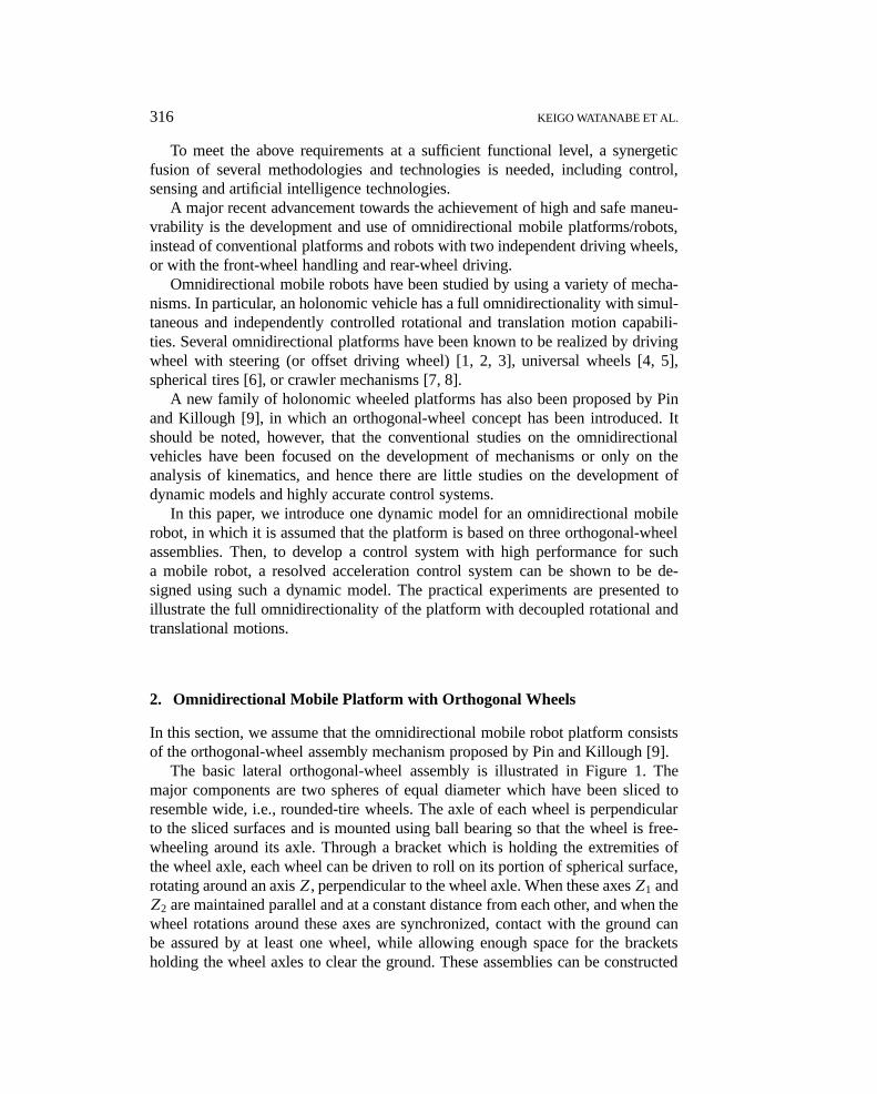
316 KEIGO WATANABE ET AL.
To meet the above requirements at a sufficient functional level, a synergeticfusion of several methodologies and technologies is needed, including control,sensing and artificial intelligence technologies.
A major recent advancement towards the achievement of high and safe maneu-vrability is the development and use of omnidirectional mobile platforms/robots,instead of conventional platforms and robots with two independent driving wheels,or with the front-wheel handling and rear-wheel driving.
Omnidirectional mobile robots have been studied by using a variety of mecha-nisms. In particular, an holonomic vehicle has a full omnidirectionality with simul-taneous and independently controlled rotational and translation motion capabili-ties. Several omnidirectional platforms have been known to be realized by drivingwheel with steering (or offset driving wheel) [1, 2, 3], universal wheels [4, 5],spherical tires [6], or crawler mechanisms [7, 8].
A new family of holonomic wheeled platforms has also been proposed by Pinand Killough [9], in which an orthogonal-wheel concept has been introduced. Itshould be noted, however, that the conventional studies on the omnidirectionalvehicles have been focused on the development of mechanisms or only on theanalysis of kinematics, and hence there are little studies on the development ofdynamic models and highly accurate control systems.
In this paper, we introduce one dynamic model for an omnidirectional mobilerobot, in which it is assumed that the platform is based on three orthogonal-wheelassemblies. Then, to develop a control system with high performance for sucha mobile robot, a resolved acceleration control system can be shown to be de-signed using such a dynamic model. The practical experiments are presented toillustrate the full omnidirectionality of the platform with decoupled rotational andtranslational motions.
2. Omnidirectional Mobile Platform with Orthogonal Wheels
In this section, we assume that the omnidirectional mobile robot platform consistsof the orthogonal-wheel assembly mechanism proposed by Pin and Killough [9].
The basic lateral orthogonal-wheel assembly is illustrated in Figure 1. Themajor components are two spheres of equal diameter which have been sliced toresemble wide, i.e., rounded-tire wheels. The axle of each wheel is perpendicularto the sliced surfaces and is mounted using ball bearing so that the wheel is free-wheeling around its axle. Through a bracket which is holding the extremities ofthe wheel axle, each wheel can be driven to roll on its portion of spherical surface,rotating around an axisZ, perpendicular to the wheel axle. When these axesZ1 andZ2 are maintained parallel and at a constant distance from each other, and when thewheel rotations around these axes are synchronized, contact with the ground canbe assured by at least one wheel, while allowing enough space for the bracketsholding the wheel axles to clear the ground. These assemblies can be constructed
JI1439TZ.tex; 21/07/1998; 11:47; p.2

CONTROL OF AN OMNIDIRECTIONAL MOBILE ROBOTS 317
Figure 1. The lateral orthogonal-wheel assembly.
Figure 2. The appearance of an omnidirectional mobile platform.
by using more than two wheels, in which each wheel axle should be allocated withless than 90◦ offset.
In the following, it is assumed that a platform is based on three assembliesallocated at an equal distance from the center of gravity (c.g.) for the robot, inwhich one assembly consists of two wheels. The actual experimental mobile robotis shown in Figure 2.
JI1439TZ.tex; 21/07/1998; 11:47; p.3

318 KEIGO WATANABE ET AL.
Figure 3. Model of an omnidirectional mobile robot.
3. Dynamic Model of the Omnidirectional Mobile Platform
Let the mobile robot be rigid moving on the work space. It is assumed that theabsolute coordinate systemOw : XwYw is fixed on the plane and the moving co-ordinate systemOm : XmYm is fixed on the c.g. for the mobile robot as shown inFigure 3.
When defining the position vector of the c.g. for the mobile robot such asSw =[xw yw]T, we have
MSw = Fw, (1)
whereFw = [Fx Fy]T is the force vector in the absolute coordinate system appliedto the center of gravity of the mobile robot andM is a symmetric positive-definitematrix asM = diag(M,M) with the massM.
Let φ denote the angle betweenXw- andXm-coordinates, i.e., the rotationalangle of the moving coordinate system with respect to the absolute coordinatesystem. When introducing the coordinate transformation matrix from the absolutecoordinate system to the moving coordinate system such as
wRm =[
cosφ − sinφsinφ cosφ
](2)
it follows that
Sw = wRmsm, (3)
Fw = wRmf m, (4)
JI1439TZ.tex; 21/07/1998; 11:47; p.4

CONTROL OF AN OMNIDIRECTIONAL MOBILE ROBOTS 319
wheresm = [xm ym]T andf m = [fx fy]T are the position vector of the c.g. and theforce vector applied to the c.g. in the moving coordinate system, respectively.
Therefore, transforming Equation (1) to the moving coordinate system gives
M(wRT
mwRmsm + sm
) = f m. (5)
Then, the dynamic properties of the mobile robot can be described as [10]:
M(xm − ymφ
) = fx, (6)
M(ym − xmφ
) = fy, (7)
Ivφ = MI , (8)
whereIv is the moment of inertia for the robot,MI is the moment around the c.g.for the robot, andfx, fy,MI are given by:
fx = −1
2D1− 1
2D2+D3, (9)
fy =√
3
2D1−
√3
2D2, (10)
MI = (D1+D2+D3)L. (11)
In addition, the driving system property [11] for each assembly is assumed to begiven by
Iwωi + cωi = kui − rDi, i = 1,2,3, (12)
whereL is the distance between any assembly and the c.g. of the robot;c is theviscous friction factor of the wheel;Di is the driving force for each assembly;r isthe radius of the wheel;Iw is the moment of inertia of the wheel around the drivingshaft;ωi is the rotational rate of the wheel;k is the driving gain factor; andui isthe driving input torque.
On the other hand, the geometrical relationships among variablesφ, xm, ym, andωi, i.e., the inverse kinematics are given by:
rω1 = −1
2xm +
√3
2ym + Lφ, (13)
rω2 = −1
2xm −
√3
2ym + Lφ, (14)
rω3 = xm + Lφ. (15)
Therefore, using Equations (6)–(15) gives:
xm = a1xm + a′2ymφ − b1(u1+ u2 − 2u3), (16)
ym = a1ym − a′2xmφ +√
3b1(u1− u2), (17)
φ = a3φ + b2(u1+ u2+ u3), (18)
JI1439TZ.tex; 21/07/1998; 11:47; p.5

320 KEIGO WATANABE ET AL.
where
a1 = −3c/(3Iw + 2Mr2
), a′2 = 2Mr2/
(3Iw + 2Mr2
),
a3 = −3cL2/(3IwL
2+ Ivr2),
b1 = kr/(3Iw + 2Mr2), b2 = krL/
(3IwL
2+ Ivr2).It is easy to find that combining Equations (2), (3), (16) and (17) yields the ap-propriate dynamic equations in the absolute coordinate system for the robot. Thus,defining the state variable for the robot asx = [xw yw φ xw yw φ]T, the manipulatedvariable asu = [u1 u2 u3]T, and the output variable asy = [xw ym φ]T yields thefollowing state equation:
x = A(x)x + B(x)u, (19)
y = Cx, (20)
where
A(x) =
0 0 0 1 0 00 0 0 0 1 00 0 0 0 0 10 0 0 a1 −a2φ 00 0 0 a2φ a1 00 0 0 0 0 a3
,
B(x) =
0 0 00 0 00 0 0b1β1 b1β2 2b1 cosφb1β3 b1β4 2b1 sinφb2 b2 b2
, C =[ 0 0 0 1 0 0
0 0 0 0 1 00 0 1 0 0 0
],
a2 = 1− a′2 = 3Iw/(3Iw + 2Mr2
),
β1 = −√
3 sinφ − cosφ, β2 =√
3 sinφ − cosφ,
β3 =√
3 cosφ − sinφ, β4 = −√
3 cosφ − sinφ.
Let the translational velocity of the robot in the absolute coordinate system beV = (x2
w + y2w)
1/2 and the azimuth of the robot in the absolute coordinate systembeψ = θ + φ. Here,θ denotes the angle betweenXm-coordinate andf m, i.e., theazimuth of the robot in the moving coordinate system. Then, it is found that
xw = V cosψ, (21)
yw = V sinψ, (22)
ψ = arctanyw
xw, (23)
JI1439TZ.tex; 21/07/1998; 11:47; p.6

CONTROL OF AN OMNIDIRECTIONAL MOBILE ROBOTS 321
where note that a counterclockwise rotation denotes the positive direction for therotational motion of the robot.
It should be noted thatXw- andYw-directional motions in (19) are coupled,because the equation of motions is derived in the absolute coordinate system.However, since the rotational angle of the robot can be assured asφ = ψ − θeven if the azimuth of the robot is changed arbitrarily, the mobile robot can realizea translational motion without changing the pose.
4. Resolved Acceleration Control
Since the dynamic equation is finally considered in the absolute coordinate system,solving Equation (19) with respect toui, i = 1,2,3, gives the following resolvedacceleration control:
u1 = β1(x∗w − a1xw + a2φyw)
6b1
+ β3(y∗w − a1yw − a2φxw)
6b1+ φ
∗ − a3φ
3b2, (24)
u2 = β2(x∗w − a1xw + a2φyw)
6b1
+ β4(y∗w − a1yw − a2φxw)
6b1+ φ
∗ − a3φ
3b2, (25)
u3 = cosφ(x∗w − a1xw + a2φyw)
3b1
+ sinφ(y∗w − a1yw − a2φxw)
3b1+ φ
∗ − a3φ
3b2, (26)
wherex∗w, y∗w andφ∗ are given by adding PI-servo or PD-servo toxwd, ywd andφd
such that
x∗w = xwd +Kxpex +Kxi
∫ t
0ex dt, (27)
y∗w = ywd +Kypey +Kyi
∫ t
0ey dt, (28)
φ∗ = φd +Kφveφ +Kφpeφ. (29)
Here,K·p is the proportional gain,K·i is the integral gain,K·v is the derivative gain,and each error is defined by:
ex = xwd− xw, (30)
ey = ywd− yw, (31)
eφ = φd− φ, (32)
JI1439TZ.tex; 21/07/1998; 11:47; p.7

322 KEIGO WATANABE ET AL.
Figure 4. A resolved acceleration control system.
where xwd, ywd and φd denote the references forxw, yw and φ, respectively. Itshould be noted that the solutionsui, i = 1,2,3, exist for allt , because the inputdistribution factorsb1 andb2 are always nonzero constants. The block diagram ofa resolved acceleration control system for the mobile robot is shown in Figure 4,in which R−1 denotes the estimated inverse dynamic model.
5. Experimental Results
We have applied the above control system to an actual mobile robot. It was assumedthat the control sampling period is 50 ms and the total experimental time is 20 s.The physical parameters of the mobile robot are as follows:
Iv = 11.25 kgm2, Iw = 0.02108 kgm2, c = 5.983× 10⁻⁶ kgm2/s,
M = 9.4 kg, L = 0.178 m, r = 0.0245 m, k = 1.0.
It was also assumed that the initial moving coordinate system is equal to the ab-solute coordinate system, and the initial value of state variable is given asx =[0 0 0 0 0 0]T.
5.1. SIMULTANEOUSLY TRANSLATIONAL AND ROTATIONAL MOTIONS
The omnidirectional mobile robot can independently achieve the translational mo-tion and the rotational motion around the c.g. in the two-dimensional plane. Tocheck this property, the holonomic property, it was assumed that the robot musttravel with a fixed azimuth angleψd = π/4 rad for 20 s, but with zero rotationalangle for 0–10 s and with a uniformly varying rotational angle fromφd = 0 rad to
JI1439TZ.tex; 21/07/1998; 11:47; p.8

CONTROL OF AN OMNIDIRECTIONAL MOBILE ROBOTS 323
Figure 5. Velocity xw for Case 1.
Figure 6. Velocity yw for Case 1.
φd = π/2 rad for 10–20 s. Although the moving velocity was to beVd = 0.05 m/sin the steady-state, a sinusoidal reference velocity was set for each 2 seconds at thestarting and ending duration.
Using theseVd andψd, the correspondingxwd andywd were derived from (21)and (22), andxwd andywd were also derived by their derivatives.
5.1.1. Case 1
Figures 5–7 show the results for the case when the servo gains are given as inTable I. In this case, it is found that the control ofφ is achieved very well, whilethe velocity control results have an overshoot.
JI1439TZ.tex; 21/07/1998; 11:47; p.9

324 KEIGO WATANABE ET AL.
Figure 7. Rotational angleφ for Case 1.
Table I. Gains for Case 1
Kφp Kφv Kxi Kxp Kyi Kyp
2.25 3.0 1.0 2.0 1.0 2.0
Table II. Gains for Case 2
Kφp Kφv Kxi Kxp Kyi Kyp
2.25 3.0 25.0 10.0 25.0 10.0
5.1.2. Case 2
To improve the responses onxw and yw, adjusted servo gains are tabulated inTable II. The corresponding control results are shown in Figures 8–13. It is foundfrom these figures that a good trajectory control result is obtained, though thereexist successive oscillations in the velocity responses. This seems to be attributedto the reason that the dc-servo-driver has a restricted resolution ability.
5.2. CIRCULAR MOTION WITH A FIXED POSE
As a motion that a conventional mobile robot cannot achieve, we can consider acircular motion with a radius of curvature less than half of the distance betweenwheels, that is, its motion has a center of rotation on the distance between wheels.The omnidirectional mobile robot, of course, can easily achieve such a motion. In
JI1439TZ.tex; 21/07/1998; 11:47; p.10

CONTROL OF AN OMNIDIRECTIONAL MOBILE ROBOTS 325
Figure 8. Velocity xw for Case 2. Figure 9. Velocity yw for Case 2.
Figure 10. Rotational angleφ for Case 2. Figure 11. Trajectory for Case 2.
Figure 12. Input torque for Case 2. Figure 13. Input voltage for Case 2.
JI1439TZ.tex; 21/07/1998; 11:47; p.11

326 KEIGO WATANABE ET AL.
Figure 14. Velocity xw for a circular path.
the following experiment, it was assumed that a circular trajectory has a radius ofcurvature 0.1 m, while the distance between wheels is 0.356 m. The resultant mov-ing velocity was given byVd = 0.04488 m/s, but a sinusoidal reference velocitywas set for each 2 seconds at the starting and ending duration. The moving azimuthwasψd = 0.0 rad for each 3 seconds at the starting and ending duration, while ithad a uniformly successive increment up to 2π rad for the remaining 14 seconds,where the robot pose, the rotational angle was fixed asφd = 0.0 rad for the wholeduration.
The corresponding control results are shown in Figures 14–19, where the servogains are the same as those tabulated in Table II. From these figures, it is seen thatsatisfactory control results are obtained without changing the servo gains.
5.3. 8CHARACTER MOTION WITH A SIMULTANEOUS ROTATION
In this section, the following 8 character path was considered to check the trackingperformance of the robot for the case when the referencesxwd andywd are changedfrequently, and to examine the effect of a time-varyingφ on the responses.
It was assumed thatVd = 0.05 m/s, but with an acceleration and deceleration foreach 2 seconds at the starting and ending duration. The 8 character was composedof two squared path, where there existed an acceleration and deceleration for 1second at each corner. The resultant path was symmetry with respect to thex-coordinate. It was also assumed that the reference rotational angle was zero for0–10 s, while it was uniformly time-increasing fromφd = 0 rad toφd = π/2 radfor 10–20 s.
The control results are shown in Figures 20–22, where the servo gains given inTable II were used. It is understood from these figures that some overshoots appear
JI1439TZ.tex; 21/07/1998; 11:47; p.12

CONTROL OF AN OMNIDIRECTIONAL MOBILE ROBOTS 327
Figure 15. Velocity yw for a circular path. Figure 16. Rotational angleφ for a circular
path.
Figure 17. Trajectory for a circular path. Figure 18. Input torque for a circular path.
Figure 19. Input voltage for a circular path. Figure 20. Velocity xw for an 8 character path.
JI1439TZ.tex; 21/07/1998; 11:47; p.13

328 KEIGO WATANABE ET AL.
Figure 21. Velocity yw for an 8 character path. Figure 22. Rotational angleφ for an 8 cha-racter path.
Figure 23. Trajectory for an 8 character path.
in the responses ofxw and yw, though the response of rotational angle tracks thereference very well. This seems to be attributed to the fact that the time requiredfor the acceleration and deceleration is too short, and in fact it was not improvedeven if the gains forxwd andywd were increased.
Furthermore, it should be noted from Figure 22 that the tracking errors appear atthe corners of the squared path. It is worth, however, to note that the time-varyingor time-invariant property of the rotational angleφ does not affect the trajectoryresponse, because the responses on the upper and bottom squared paths are approx-imately symmetric with respect to thex-coordinate. A compensation approach,such as a sliding mode control for the resolved acceleration control system with amodeling error, may be needed to improve the control response.
JI1439TZ.tex; 21/07/1998; 11:47; p.14

CONTROL OF AN OMNIDIRECTIONAL MOBILE ROBOTS 329
6. Conclusions
In this paper, we have derived a dynamic model for an omnidirectional holo-nomic mobile robot, whose platform was assumed to be based on three lateralorthogonal-wheel assemblies. Then, the resolved acceleration control system wasderived using such a model, and several experimental results were presented show-ing that the present control system was effective for controlling such a mobilerobot.
We refer to [12] for the control results through the stochastic fuzzy control ap-proach. See also [13] for the detailed construction problem of the omnidirectionalmobile robot using some orthogonal wheel mechanisms.
Representative examples of mobile health-care service robot prototypes (design,implementation, control, human-robot interfacing, operation) can be found in [14–20].
References
1. Nakano, E. and Koyachi, N.: An advanced mechanism of the Omni-Directional Vehicle (ODV)and its application to the working wheelchair for the disabled, in:Proc. of ’83 Int. Conf. onAdvanced Robotics, 1983, pp. 277–284.
2. Nakano, E., Mori, Y., and Takahashi, T.: Study of the mechanism and control of Omni-Directional Vehicle, in:Proc. of the 12th Annual Conf. of RSJ1, 1994, pp. 369–379 (inJapanese).
3. Wada, M., Tominaga, Y., and Mori, S.: Design of an omnidirectional holonomic vehicle, in:Proc. of the 13th Annual Conf. of RSJ1, 1995, pp. 145–146 (in Japanese).
4. Muir, P. F. and Neuman, C. P.: Kinematic modeling of wheeled mobile robots,J. RoboticSystems4 (1987), 281–340.
5. Asama, H., Bogoni, L., Sato, M., Kaetsu, H., and Endo, I.: Kinematics of an omnidirectionalmobile robot with 3-DOF decoupling drive mechanism, in:Proc. of the 12th Annual Conf. ofRSJ1, 1994, pp. 367–368 (in Japanese).
6. Nishikawa, A., West, M., and Asada, H.: Development of a holonomic omnidirectional vehicleand an accurate guidance method of the vehicles,J. of the Robotics Society of Japan13(2)(1995), 249–256 (in Japanese).
7. Hirose, S. and Amano, S.: The VUTON: High payload, high efficiency holonomic Omni-Directional Vehicle, in:Proc. of JSME Annual Conf. on Robotics and Mechatronics, 1993,pp. 350–355 (in Japanese).
8. Hirano, T., Chen, P., and Toyota, T.: A fundamental study on omnidirectional vehicle (1) –Omnidirectional running mechanism for offroad, in:Proc. of the 14th SICE Kyushu BranchAnnual Conf., 1995, pp. 273–274 (in Japanese).
9. Pin, F. G. and Killough, S. M.: A new family of omnidirectional and holonomic wheeledplatforms for mobile robots,IEEE Trans. Robotics Automat.10(2) (1994), 480–489.
10. Iwatsuki, M., Nakano, K., and Ohuchi, T.: Target point tracking control of robot vehicle byfuzzy reasoning,Trans. of the Soc. Instrum. Control Engineers (SICE)27(1) (1991), 70–76 (inJapanese).
11. Saito, M. and Tsumura, T.: Collision avoidance among multiple mobile robots – A localapproach based on nonlinear programming,Trans. of the Institute of Systems, Control andInformation Engineers3(8) (1990), 252–260 (in Japanese).
JI1439TZ.tex; 21/07/1998; 11:47; p.15

330 KEIGO WATANABE ET AL.
12. Tang, J., Nomiyama, A., Watanabe, K., and Yubazaki, N.: Stochastic fuzzy control for an au-tonomous mobile robot, in:Proc. of the 1996 IEEE Int. Conf. on Systems, Man and Cybernetics,1, Beijing China, 1996, pp. 316–321.
13. Tang, J., Watanabe, K., and Shiraishi, Y.: Design of traveling experiment of an omnidirectionalholonomic mobile robot, in:Proc. of the 1996 IEEE/RSJ Int. Conf. on Intelligent Robotics andSystems (IROS ’96), 1, Osaka, Japan, 1996, pp. 66–73.
14. Klafter, R. D.: Mobile robots, research and development, in: R. C. Dorf and S. Y. Nof(eds),Internat. Encyclop. of Robotics: Applications and Automation, Wiley, New York, 1988,pp. 920–943.
15. Kimura, I. and Tadano, J.: Guide and carry robot for hospital use,Advanced Robotics3(3)(1989), 213–220.
16. Kawamura, K. and Iskarous, M.: Trends in service robots for the disabled and the elderly, in:Proc. of the 1994 Int. Conf. on Intelligent Robots and Systems (IROS ’94), Munich, Germany,1994, pp. 1647–1654.
17. WORKSHOP WS3: Robots for the disabled and elderly people, in:Proc. 1995 Int. Conf. onRobotics and Automation, Nagoya, Aichi, Japan, 1995.
18. Rembold, U., Dillmann, R., Hertzberger, L. D., and Kanade, T. (eds):Intelligent AutonomousSystems, IOS Press, Amsterdam/Oxford, 1995.
19. Fischer, C., Buss, M., and Schmidt, G.: Hierarchical supervisory control of a service robotusing human-robot interface, in:Proc. of the 1996 Int. Conf. on Intelligent Robots and Systems(IROS ’96), Osaka, Japan, 1996, pp. 1408–1416.
20. Tzafestas, S. G., Koutsouris, D., and Katevas, N.:Mobile Robotics Technology for Health-CareServices(Proc. of the 1st EEC-TIDE MobiNet Symp.), Athens, May, 1997.
JI1439TZ.tex; 21/07/1998; 11:47; p.16
Copyright © 2022 FDOKUMEN