Identification of immersed obstacles via boundary measurements
Upload
independentCategory
view
1download
0
Obstacles Avoidance for Car-Like RobotsIntegration And Experimentation on Two Robots
Olivier Lefebvre∗ Florent Lamiraux∗ Cédric Pradalier†∗[email protected] †[email protected]
GRAVIR - INRIA - INPGLAAS-CNRS INRIA Rhône-Alpes
7, av du Colonel Roche 600, av. de l’Europe31077 Toulouse Cedex 4 38334 Saint Ismier Cedex
FRANCE FRANCE
Abstract— In this paper we address the problem of obsta-cles avoidance for car-like robots. We present a generic non-holonomic path deformation method that has been applied ontwo robots. The principle is to perturb the inputs of the systemin order to move away from obstacles and to keep the non-holonomic constraints satisfied. We present an extension of themethod to car-like robots. We have integrated the method on tworobots (Dala and CyCab) and carried out experiments that showthe portability and genericity of the approach.
Fig. 1. Robots Dala (on left) and CyCab
INTRODUCTION
Computing a collision-free trajectory for a non-holonomicmobile robot located in a map is a difficult task. It dealswith two extensively studied topics : geometric path planningand non-holonomic motion. Nevertheless, if we want to applyresults of research carried out in robotics to automatic motionof road vehicles for instance, some problems are still to besolved. Cars that would park automatically or that would beable to manage a stop-and-go mode in traffic jam, are potentialindustrial applications of non-holonomic motion planning. Inthis context, collision avoidance at the time of the execution ofthe trajectory is a prerequisite. A previously planned trajectorymay have to be deformed during execution to avoid collisions.There are several reasons for that :• the map of the environment can be inaccurate,• new obstacles may appear that were not in the map,• if the planned trajectory is not exactly followed due to a
poor localization of the robot, unexpected collisions mayoccur.
Numerous approaches have been proposed to overcomethese difficulties. [1] proposed a method to deform online the
path followed by the robot in order to get away from obstaclesdetected along the motion. This approach has been extendedto the case of a unicycle-like mobile robot by [2] and then tothe case of a holonomic mobile manipulator by [3]. In bothpapers, the geometry of the robot is approximated by a set ofballs and no or only one very simple non-holonomic constraintis treated.
The non-holonomic path deformation method [4] is ageneric approach of the on-line trajectory deformation issue.It enables to deform a trajectory at execution time so thatit moves away from obstacles and that the non-holonomicconstraints of the system keep satisfied. It can be applied to anynon-holonomic system, and was initially elaborated on robotHilare 2 towing a trailer [5] and used in the context of pathoptimization for trucks carrying huge airplanes components onnarrow roads.
This paper presents the integration of the method on twonon-holonomic systems. Our contribution is the extension ofthe method in order to respect the curvature bound of a car-like robot during the deformation process (see sec. II). We alsoaddress in section III the issue of the algorithm integration ondifferent systems with different architectures. Eventually, wepresent some convincing experimental results in section IV,that illustrate the genericity of the method and its portability.
Fig. 2. Direction of deformation created by unexpected obstacles

I. THE NON-HOLONOMIC PATH DEFORMATION METHOD
The path deformation method we present is a generic pathoptimization method upon a certain criterion. In the contextof real-time obstacle avoidance, this criterion is a potentialfunction that increases when the path gets closer to obstacles.The principle of the method is the following.Given a feasiblepath for a system, possibly in collision, the path is iterativelydeformed in such a way that it moves away from obstacles.
We first need to compute apotential function along thepath, that increases when the distance of the path to the obsta-cles decreases. Then adirection of deformation is computedin order to make this potential decrease, that is for the pathto get away from obstacles. The seminal idea of the methodis then to establish arelationship between the direction ofdeformation and the inputs of the systemrepresented bythe mobile robot. We compute input perturbations that willmake the path go in the direction of deformation. If we wantindeed the deformed path to be feasible by the system, notany path deformation that would make the potential decreaseis admissible.
We present here the principle of the method. We referinterested reader to [4] for further details.
A. Nonholonomic systems
A drift-less non-holonomic system of dimensionn is char-acterized by a set ofk < n vector fieldsX1(q),...,Xk(q),whereq ∈ C = Rn is the configuration of the system. Foreach configurationq, the admissible velocities of the systemare the linear combinations of theXi(q)’s. Equivalently, apath q(s) defined over an interval[0, S] is a feasible path ifand only if:
∀s ∈ [0, S] q′(s) =k∑i=1
ui(s)Xi(q) (1)
whereq′(s) is the derivative ofq(s).
B. Infinitesimal Path Deformation
A path is a mapping from an interval[0, S] into theconfiguration spaceC = Rn of the robot. A path is thuscompletely defined by the value of the inputs of system (1)on interval[0, S]: the ui(s) with 1 ≤ i ≤ k.
To deform a given path we only need to perturb theinput functionsu1(s), ..., uk(s) of the initial pathq(s). Forthat, we definen real functionsv1(s),...,vn(s) called inputperturbationsand a real numberτ that gives the deformationamplitude. Then a deformed path can be represented by afunction of two variables:q(s, τ). The inputs of the systemare in this caseui(s) + τvi(s).
Because we only perturb the entries of the system, we aresure that the non-holonomic constraints remain satisfied afterthe deformation.
Figure 2 represents the direction of deformationη(s) createdby some obstacles. It corresponds to the infinitesimal pathdeformation due to infinitesimal inputs perturbations :η(s) =∂q∂τ (s, 0).
Therefore, we have established a relation between the inputperturbations and the direction of deformation.
C. A Relationship between Obstacles and Path Deformation
We now need to establish a relation between the obstaclesand the direction of deformation. Given a set of obstaclesdetected while following the current path, we define a potentialfield U(q) in the configuration space in such a way that thevalue of the potential increases when the robot gets closer toobstacles.
From the potential field in the configuration space, we definethe potential of the current path by summingU(q) along thepath:
V =∫ S
0
U(q(s))ds
To make the path go away from obstacles, we choose thefunction v(s) = (v1(s)...vn(s)) that minimizes the first-ordervariation of the path potential (i. e. the first-order derivativeof the path potential when the first-order variation of the pathis η(s)):
∂V
∂τ(0) =
∫ S
0
∂U
∂q(q(s))T η(s)ds (2)
We emphasize the fact that only the gradient of the obstaclepotential field is of interest to us. The way it is computed isthe subject of section II-A.
This closes the loop: from a given obstacle potential field,we compute a direction of deformation that minimizes thegradient of the potential. Then the direction of deformationη(s) provides us with the input perturbations to be appliedto the dynamical system 1 so that the path gets away fromobstacles.
D. Take into account the boundary conditions
The path optimization method we present leave free thechoice of boundary conditions. That is in our case the initaland goal configurations of the deformed path. In fact we wantthe initial and goal configurations of the trajectory not to bechanged by the deformation process. Therefore, we imposethe following boundary conditions to the deformation process:∀τ ∈ [0,+∞),q(0, τ) = q(0, 0) and q(S, τ) = q(S, 0). Thecomputation of the projection of the controls of system (1)over the subspace characterized by these boundary conditionsis presented in [5].
II. EXTENSIONS OF THENON-HOLONOMIC PATH
DEFORMATION METHOD
We present in this section some extensions of the method.In a first part we give some details about the obstacle potentialfield computation. Then in a second part we present the issueof the bounded steering angle of a non-holonomic system.
The deformation process can indeed increase the curvatureof a path and there is no guarantee that it will not exceed itsbound. We present a method to keep the path curvature afterthe deformation, below a given bound. The main idea is toconsider the curvature bound as an obstacle.

A. Obstacle Potential Field Computation
In order for the deformation method to calculate a directionof deformation, we must compute a continuous potential fieldfunction that increases when the robot gets closer to obstacles.We present here how to effectively compute this potential field.
Given a perception of the environment and a trajectory, wecan compute a set of obstacle points whose distances to anypoint of the workspace are known. LetM be a point in theworkspaceW . We noteνi(M) the potential generated by anobstacle pointPi located at distanced from M. Let R(q) bea point of the robot, it can be the closest point to obstaclePifor instance.Thenνi(R(q)) stands for the potential generated by obstaclePi when robot is at configurationq.
We notice that there exists a mapping from(CxW ) into R:(q, Pi) → d, so that the potentialνi can be expressed as afunction of distanced.
The obstacle potential field at a configurationq is the sumof the potentials relative to each obstacle :
U(q) =∑i
νi(R(q)) (3)
The gradient of the potential field in the configuration spaceis obtained by differentiating equation 3:
∂U
∂q(q) =
∑i
∇νi(R(q))∂R
∂q(q)
If we remember eq. (2), we are only interested in thegradient of the potential in the configuration space. We seefrom previous expression that∇νi(R(q)) can be any vectorof the workspace. For genericity reasons, we make this vectorderive from a potential, so that it is equivalent to a force:fi(R(q)) = −∇νi(R(q)).
We want this “force” to be null when obstacles are far fromthe robot (d > d1) and to increase when the distanced toobstacles gets close to zero. A function which verifies theseassumptions for obstaclePi is for instance such that:
‖fi(R(q))‖ = 1(d+d0)2 − 1
(d1+d0)2 if 0 ≤ d ≤ d1
‖fi(R(q))‖ = 0 if d > d1(4)
And the expression of the potential from which the functionderives is :
νi(R(q)) = 1d+d0
+ d(d1+d0)2 if 0 ≤ d ≤ d1
νi(R(q)) = 1d1+d0
+ d1(d1+d0)2 if d > d1
Where d0 is a parameter that enables the potential as afunction of d to be defined on the interval[0,+∞].
The gradient of the potential in the configuration space isobtained by multiplying the force in the workspace by theJacobian ofR(q) in eq. 4.
We have presented an explicit manner to compute anobstacle potential field which satisfies our assumptions. Thegradient of this potential is the criterion minimized by theoptimization method, so that the deformation makes the pathmove away from obstacles.
B. Bounded curvature of a Car-like Robot
We have integrated the non-holonomic path deformationmethod on a robot with a car-like kinematic : the CyCab. Asa car, the CyCab has a bounded steering angle. We present anextension of the method that takes into account the curvaturebound of the system during the deformation process. Weexplain how this extension can also be applied to a two-wheelsrobot.
1) Car Kinematic Model:A car-like robot has 4 configu-ration variablesx, y, θ, φ as shown in figure 4 and two non-holonomic constraints. The front wheel angles are computedin order for the curvature center notedO to belong to therear axle line. The angleφ is the angle that would place thecurvature center of a wheel located in the middle of the frontaxle, on the same line.
φ
θ
v
(x,y)
O
l
1/κ
Fig. 3. Car Kinematic Model. Four configuration variablesx, y, θ, φ.Curvatureκ is derived from steering angleφ and distancel to rear axle.
The control vector fields for such a system are:
X1 =
cos θsin θtanϕl0
X2 =
0001
(5)
2) How to Respect the Curvature Bound During the Defor-mation Process:As a car, the CyCab as a bounded curvature.That is:0 ≤ κ ≤ κmax. It results in a constraint on its steeringangle:0 ≤ φ ≤ φmax, with φ = arctan (κl).
If the non-holonomic path deformation method ensuresthat the wheels non-holonomic constraints of the system arerespected, there is absolutely no guarantee that the deformedpath will respect the curvature bound. And it can happenthat given an initial path in collision, the deformation processproduces a collision free-path with a non-admissible curvaturefor the system.
To counter this effect, the idea is to consider the steeringangle boundφmax as an obstacle. We define a potential onthe steering angleφ in a similar way as the obstacle potentialfield II-A. The gradient which derives from this potential hasthe following expression:fφ(q) =
0 if 0 ≤ |φ| ≤ (φmax − d1)1
((φ−φmax)+d0)2 − 1(d1+d0)2 if (φmax − d1) ≤ |φ| ≤ φmax
1(d0)2 − 1
(d1+d0)2 if |φ| ≥ φmax(6)

where the parametersd0 andd1 represent the same magni-tudes as in equation 4, but are here tuned to be homogeneouswith angle values. Figure 5 represents the graph of‖fφ(q)‖.When at a configuration the value ofφ is close to its bound,the gradient of the potential increases.
φ0−
Force value
φ φmax max
forcemax
d1d1
Fig. 4. Norm of the “force”fφ(q) due to the steering angle. The gradientof the potential field is indeed equivalent to a force. The value of the normof the “force” increases when the steering angle gets closer to its bound.
θ
ϕ
(x,y)
Fig. 5. Mobile robot Dala as a car-like robot: a non-holonomic system ofdimension 4 with two non holonomic constraints.
3) A Virtual Wheel on a Two-Wheel Robot:We have alsointegrated the method on mobile robot Dala, an ATRV (seefigure 6). This mobile robot is a differential-driven robot:rotation is performed by applying different velocities to theright and left wheels. In spite of its four wheels, it has thesame kinematic as a two-wheel robot whose virtual axle wouldbe located in the middle of the real axles. To avoid too muchslipping and unnatural trajectories we consider robot Dala as acar-like robot with a bounded virtual steering angle. By usingthe same extension as before, we ensure this curvature boundis respected.
III. E FFECTIVE INTEGRATION OF THEMETHOD ON TWO
ROBOTS
The non-holonomic path deformation method is generic: itcan be applied to any system subject to some non-holonomicconstraints. We present in this section how we effectivelyintegrated this method on two robots : CyCab and Dala.We describe the modular software architecture in which themethod has been developed. We give some details about theway the obstacles are perceived, and about the localizationissue in the context of the path deformation.
A. Modular Software Architecture
The algorithm of the deformation method has been imple-mented in a GenoMmodule[6]. A moduleis a software entityperforming some functions, and capable of communicating
with other modules. Amodulecan for instance have someshared data structures that it updates, and that other modulescan read.
Moreover the integration of the algorithm on robot CyCabhad several constraints to cope with. First of all, the methodhas been developed at LAAS in Toulouse, and the robot CyCabis located at INRIA in Grenoble. Then the method had alreadybeen implemented in GenoM architecture, and we wanted toreuse these modules. Eventually the control algorithm of theCyCab had also already been implemented, but not in GenoMmodules. Figure 7 presents the architecture chosen to copewith these constraints.
Legend GENOM MODULES
Send Command
Position
Get Command
Send Command
Communicate with cycab
Follow the trajectory
Compute and
Laser points segmentation
Get Position and Laser data
Laser Segments
Laser Points
Laser data
Laser scan
Localization : SLAM
Execute the trajectory
LASER DATAPOSTER
CYCAB ROBOT
CYCAB module
FOLLOW module
PILO module
Deform the trajectory
POSTERPATH
ReferenceConfiguration
POSTERTRACKING
module
poster
output
input
trajectoryPlanned
Computed Path
Fig. 6. Software Architecture of the Non-Holonomic path DeformationMethod Integration on Robot CyCab. The CyCab communicates with GenoMmodules: the two systems are distinct.
B. Obstacles Perception by the Robot
To compute the obstacles potential field along the path, weneed to perceive obstacles. On both robots CyCab and Dala,a laser telemeter gives the distance to the closest obstacles inan horizontal plane in every direction. It returns at most 360points for a180 ◦ scan. A GenoM module is dedicated to thetreatment of these points.
C. Localization of the Robot
The path deformation method can bear localization errors. Ifthe robot is poorly localized during the execution of a giventrajectory, a configuration that was planned as collision-freecan happen to be in collision. But since the path deformationtakes into account the distance to obstacles, it will deformthe trajectory so that it moves away from obstacles. Thus, thepath deformation can somehow make some localization errorsnon-critical.
The localization methods are different on robots CyCab andDala:
On robot Dala an odometric sensor provides the linear andangular velocities, and the robot configuration is obtained by
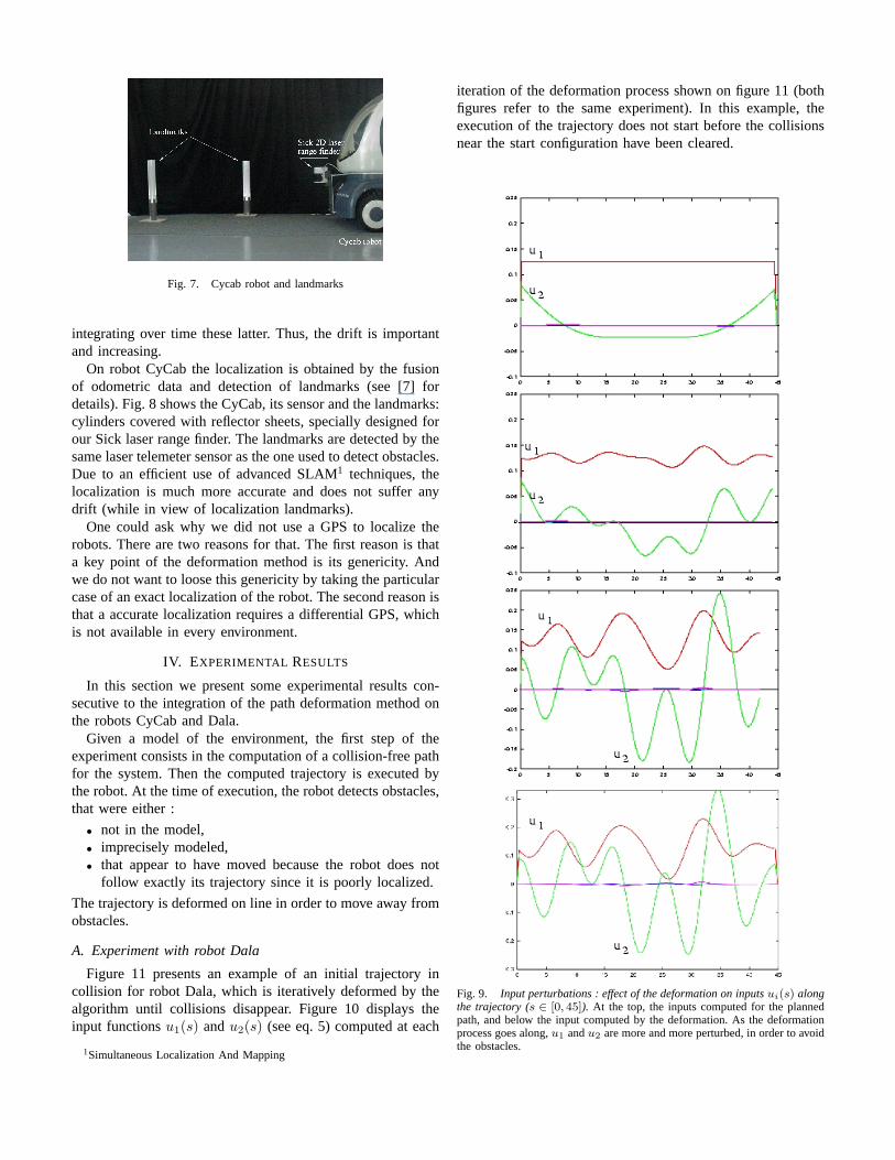
Fig. 7. Cycab robot and landmarks
integrating over time these latter. Thus, the drift is importantand increasing.
On robot CyCab the localization is obtained by the fusionof odometric data and detection of landmarks (see [7] fordetails). Fig. 8 shows the CyCab, its sensor and the landmarks:cylinders covered with reflector sheets, specially designed forour Sick laser range finder. The landmarks are detected by thesame laser telemeter sensor as the one used to detect obstacles.Due to an efficient use of advanced SLAM1 techniques, thelocalization is much more accurate and does not suffer anydrift (while in view of localization landmarks).
One could ask why we did not use a GPS to localize therobots. There are two reasons for that. The first reason is thata key point of the deformation method is its genericity. Andwe do not want to loose this genericity by taking the particularcase of an exact localization of the robot. The second reason isthat a accurate localization requires a differential GPS, whichis not available in every environment.
IV. EXPERIMENTAL RESULTS
In this section we present some experimental results con-secutive to the integration of the path deformation method onthe robots CyCab and Dala.
Given a model of the environment, the first step of theexperiment consists in the computation of a collision-free pathfor the system. Then the computed trajectory is executed bythe robot. At the time of execution, the robot detects obstacles,that were either :
• not in the model,• imprecisely modeled,• that appear to have moved because the robot does not
follow exactly its trajectory since it is poorly localized.
The trajectory is deformed on line in order to move away fromobstacles.
A. Experiment with robot Dala
Figure 11 presents an example of an initial trajectory incollision for robot Dala, which is iteratively deformed by thealgorithm until collisions disappear. Figure 10 displays theinput functionsu1(s) andu2(s) (see eq. 5) computed at each
1Simultaneous Localization And Mapping
iteration of the deformation process shown on figure 11 (bothfigures refer to the same experiment). In this example, theexecution of the trajectory does not start before the collisionsnear the start configuration have been cleared.
Fig. 9. Input perturbations : effect of the deformation on inputsui(s) alongthe trajectory (s ∈ [0, 45]). At the top, the inputs computed for the plannedpath, and below the input computed by the deformation. As the deformationprocess goes along,u1 andu2 are more and more perturbed, in order to avoidthe obstacles.

Fig. 8. A trajectory planned byrobot CyCab from a parking lotto another.On top, experimentsituation. On bottom, the tra-jectory deformation, bird’s-eyeviewed. An obstacle lies on thetrajectory, and the CyCab has todeform its trajectory at execu-tion time.
B. Experiment with robot CyCab
Figure 9 presents an experiment of automatic parking. RobotCyCab has to move from a parking lot to another. An obstaclewhich was not in the map used to plan the trajectory, liesbetween the two lots. The CyCab deforms its trajectory toavoid this new obstacle while keeping its curvature below its
Fig. 10. Trajectory deformation.Two obstacles detected by a laser rangefinder lie on the path planned by the robot Dala (at the top). The trajectoryis deformed in order to get a collision free path (at the bottom).
bound.
CONCLUSION
In this paper we have presented a generic non-holonomicpath deformation method. It enables a given trajectory fora system to be deformed on line so that it moves awayfrom obstacles. It ensures the non-holonomic constraints keepsatisfied after the deformation.
We have extended the method in order for the deformationprocess to respect a given curvature bound of the trajectory.For that we have defined a potential field on the steering angle,in a similar way to the obstacles potential field.
These experimental results validate the genericity of theapproach. Furthermore, effective implementation on severaldifferent platforms (Dala, CyCab) with different architectures(Linux, Sun, VxWorks,...) proves the genericity and theportability of involved techniques.
Acknowledgment: This work has been partially supportedby the European Project MOVIE (IST-2001-39250).
REFERENCES
[1] S. Quinlan, “Real-time modification of collision free paths,” Ph.D. dis-sertation, Stanford University, 1995.
[2] M. Khatib, H. Jaouni, R. Chatila, and J.-P. Laumond, “Dynamic pathmodification for car-like nonholonomic mobile robots,” inInternationalConference on Robotics and Automation. Albuquerque, NM: IEEE, Apr.1997.
[3] O. Brock and O. Khatib, “Real-time replanning in high dimensionalconfiguration spaces using sets of homotopic paths,” inInternationalConference on Robotics and Automation. San Francisco, CA: IEEE,Apr. 2000, pp. 550–555.
[4] F. Lamiraux, D. Bonnafous, and C. V. Geem,Control Problems inRobotics. Springer, 2002, ch. Path Optimization for NonholonomicSystems: Application to Reactive Obstacle Avoidance and Path Planning.
[5] F. Lamiraux and D. Bonnafous, “Reactive trajectory deformation for non-holonomic systems: Application to mobile robots,” inIEEE InternationalConference on Robotics and Automation, 2002, pp. pp 3099–3104.
[6] S. Fleury, M. Herrb, and R. Chatila, “Genom: a tool for the specificationand the implementation of operating modules in a distributed robotarchitecture,” inIROS, Grenoble, France, vol. 2, Sept. 1997, pp. 842–848.
[7] C. Pradalier and S. Sekhavat, “Concurrent localization, matching and mapbuilding using invariant features,” inProc. IEEE Int. Conf. on IntelligentRobots and Systems, 2002.
Copyright © 2022 FDOKUMEN