
Large-scale RINA Experimentation on FIRE+ - ARCFIRE project
99
Grant Agreement No.: 687871 ARCFIRE Large-scale RINA Experimentation on FIRE+ Instrument: Research and Innovation Action Thematic Priority: H2020-ICT-2015 D3.1 Integrated software ready for experiments: RINA stack, Management System and measurement framework Due date of Deliverable: Month 18 Actual submission date: Month 18 Start date of the project: January 1st, 2016. Duration: 30 months version: V1.0 Project funded by the European Commission in the H2020 Programme (2014-2020) Dissemination level PU Public X PP Restricted to other programme participants (including the Commission Services) RE Restricted to a group specified by the consortium (including the Commission Services) CO Confidential, only for members of the consortium (including the Commission Services)
-
Upload
khangminh22 -
Category
Documents
-
view
4 -
download
0
Transcript of Large-scale RINA Experimentation on FIRE+ - ARCFIRE project
Grant Agreement No.: 687871
ARCFIRE
Large-scale RINA Experimentation on FIRE+
Instrument: Research and Innovation ActionThematic Priority: H2020-ICT-2015
D3.1 Integrated software ready for experiments: RINA stack,Management System and measurement framework
Due date of Deliverable: Month 18Actual submission date: Month 18
Start date of the project: January 1st, 2016. Duration: 30 monthsversion: V1.0
Project funded by the European Commission in the H2020 Programme (2014-2020)
Dissemination level
PU Public X
PP Restricted to other programme participants (including the Commission Services)
RE Restricted to a group specified by the consortium (including the Commission Services)
CO Confidential, only for members of the consortium (including the Commission Services)

D3.1: Integrated software readyfor experiments
Document: ARCFIRE D3.1
Date: June 30th 2017
H2020 Grant Agreement No. 687871
Project Name Large-scale RINA Experimentation on FIRE+
Document Name Deliverable 3.1
Document Title Integrated software ready for experiments: RINA stack,
Management System and measurement framework
Workpackage WP3
Authors
Vincenzo Maffione (NXW)
Gino Carrozzo (NXW)
Nicola Ciulli (NXW)
Marco Capitani (NXW)
Eduard Grasa (i2CAT)
Leonardo Bergesio (i2CAT)
Miquel Tarzan (i2CAT)
Dimitri Staessens (imec)
Sander Vrijders (imec)
Sven van der Meer (LMI)
Editor Vincenzo Maffione (NXW)
Delivery Date June 30th 2017
Version v1.0
2

D3.1: Integrated software readyfor experiments
Document: ARCFIRE D3.1
Date: June 30th 2017
Executive Summary
The success of ARCFIRE strongly depends on the availability of a stable and relatively scalableRINA implementation and related software. The experiments that will be carried out by WP4(as planned by D4.3) require the implementation to support hundreds (or thousands) of nodes,hundreds of concurrent flows and several DIFs (up to 5 levels). As a consequence, a major leap isnecessary starting from the software packages released by FP7-PRISTINE (that is the IRATI stackand the DIF Management System), which was limited to experiments with no more than 30-40nodes.
In order to allow the project to meet its scalability requirements (as stated by Objective 2),T3.1 and T3.2 have focused on improving the RINA implementation and DMS, respectively. T3.4has defined a common background in terms of development cycle and verification strategy, andwill play an essential role also in the second part of the project. As soon as the experimentsstart, their feedback (bugs, logic problems, etc.) is expected to require a substantial amount ofwork towards fixes and further software hardening. This is not in contradiction with the WP3work performed during the first phase of the project, as many software issues show up only withlarge-scale experiments and different varieties of physical/virtual machines, NIC models and otherhardware features.
Finally, considerable effort was put in the design and development of a generic and extensibleexperimentation framework for RINA networks, which is meant to outlive ARCFIRE. The frame-work allows to specify and run a test scenario in a way that is independent on the specific RINAimplementation and testbed to be used. In this way, adding support for different (future) RINAimplementations and more testbeds only requires the writing of a small Python plugin.
Structure of this document
Section 1 describes the common integration and verification system, based on a well-defined au-tomated workflow to progress the RINA software and check for functional correctness. Such asystem is based on a custom dynamic verification tool, the IRATI demonstrator [1], that has beenfurther automated by means of integrating it with Buildroot [2]. Sections 2 and 3 report on var-ious enhancements to the RINA stack implementation and the DMS. The IRATI stack has beenenhanced with a number of new features like a developer-friendly powerful POSIX-like C API forRINA applications (together with some meaningful applications), improved integration with theLinux kernel network subsystem (to reduce data copies), design of shim DIF over Wifi, and more.
Finally, section 4 presents rumba, the measurement framework designed and developed byARCFIRE for its experiments. Rumba is a Python library that allows the user to programmaticallydefine and deploy RINA networks, with an API that is independent of the particular RINA imple-mentation and the testbed used. Support for more RINA implementations and additional testbedscan be easily added by means of plugins.
3

D3.1: Integrated software readyfor experiments
Document: ARCFIRE D3.1
Date: June 30th 2017
A note about ARCFIRE technical contributions
ARCFIRE leverages most of the software developed by its parent projects FP7-PRISTINE andFP7-IRATI (e.g. the IRATI stack and SDK, the IRATI demonstrator, the DMS) and by other opensource projects (e.g. rlite). Nevertheless, the contributions and enhancements presented in thisdocument have been originated solely by the work of the ARCFIRE consortium, except whereexplicitly stated differently in the text.
In summary, ARCFIRE owns the following contributions: (i) extensions to the IRATI demon-strator to integrate Buildroot, and Buildroot support for IRATI, DMS and rlite; (ii) all the enhance-ments related to the RINA stack implementations reported in section 2; (iii) the enhancements tothe DMS reported in section 3; and (iv) the Rumba measurement framework described in section 4.
4

D3.1: Integrated software readyfor experiments
Document: ARCFIRE D3.1
Date: June 30th 2017
Table of Contents
1 Software integration and verification 71.1 Overview of RINA software packages . . . . . . . . . . . . . . . . . . . . . . . 7
1.1.1 The IRATI RINA implementation . . . . . . . . . . . . . . . . . . . . . 71.1.2 The light RINA implementation . . . . . . . . . . . . . . . . . . . . . . 81.1.3 The DIF Management System . . . . . . . . . . . . . . . . . . . . . . . 91.1.4 The measurement and analysis framework . . . . . . . . . . . . . . . . . 10
1.2 Software integration plan . . . . . . . . . . . . . . . . . . . . . . . . . . . . . . 111.2.1 The IRATI stack . . . . . . . . . . . . . . . . . . . . . . . . . . . . . . 111.2.2 DIF Management System . . . . . . . . . . . . . . . . . . . . . . . . . 111.2.3 Measurement and analysis framework . . . . . . . . . . . . . . . . . . . 12
1.3 Software verification plan . . . . . . . . . . . . . . . . . . . . . . . . . . . . . . 131.3.1 Generating images with Buildroot . . . . . . . . . . . . . . . . . . . . . 141.3.2 Buildroot extensions for IRATI, DMS and rlite . . . . . . . . . . . . . . 151.3.3 Demonstrator tools enhanced with Buildroot . . . . . . . . . . . . . . . 17
2 Enhancements to the RINA stack implementations 192.1 A POSIX-like API for RINA . . . . . . . . . . . . . . . . . . . . . . . . . . . . 19
2.1.1 API walkthrough . . . . . . . . . . . . . . . . . . . . . . . . . . . . . . 202.1.2 API specification . . . . . . . . . . . . . . . . . . . . . . . . . . . . . . 222.1.3 Mapping sockets API to RINA API . . . . . . . . . . . . . . . . . . . . 272.1.4 Example applications . . . . . . . . . . . . . . . . . . . . . . . . . . . . 312.1.5 Updates to the IRATI implementation . . . . . . . . . . . . . . . . . . . 36
2.2 Improved integration with the network device layer . . . . . . . . . . . . . . . . 392.2.1 A performance issue . . . . . . . . . . . . . . . . . . . . . . . . . . . . 392.2.2 Overview of Linux Networking subsystem . . . . . . . . . . . . . . . . 402.2.3 The new SDU/PDU/PCI data model and API . . . . . . . . . . . . . . . 412.2.4 Transmission workflow . . . . . . . . . . . . . . . . . . . . . . . . . . . 472.2.5 Receive workflow . . . . . . . . . . . . . . . . . . . . . . . . . . . . . . 482.2.6 Conclusions and next steps . . . . . . . . . . . . . . . . . . . . . . . . . 49
2.3 Shim IPC Process over WiFi . . . . . . . . . . . . . . . . . . . . . . . . . . . . 512.3.1 Linux Wireless Networking . . . . . . . . . . . . . . . . . . . . . . . . 522.3.2 Data path and Management paths . . . . . . . . . . . . . . . . . . . . . 542.3.3 Introduction to hostapd and wpa supplicant . . . . . . . . . . . . . . . . 552.3.4 Design and implementation of the Shim DIF over WiFi . . . . . . . . . . 562.3.5 Changes to the IPCM Daemon: Mobility Manager . . . . . . . . . . . . 60
2.4 Support for seamless renumbering . . . . . . . . . . . . . . . . . . . . . . . . . 612.4.1 Updates to librina . . . . . . . . . . . . . . . . . . . . . . . . . . . . . . 62
5

D3.1: Integrated software readyfor experiments
Document: ARCFIRE D3.1
Date: June 30th 2017
2.4.2 Updates to the kernel . . . . . . . . . . . . . . . . . . . . . . . . . . . . 662.4.3 Updates to rinad: IPC Process Daemon . . . . . . . . . . . . . . . . . . 67
2.5 IP over RINA . . . . . . . . . . . . . . . . . . . . . . . . . . . . . . . . . . . . 692.5.1 Service model and application naming convention . . . . . . . . . . . . 692.5.2 Interaction with the Linux kernel IP stack . . . . . . . . . . . . . . . . . 712.5.3 Complete workflow example . . . . . . . . . . . . . . . . . . . . . . . . 712.5.4 Implementation: user-space . . . . . . . . . . . . . . . . . . . . . . . . 732.5.5 Implementation: kernel-space . . . . . . . . . . . . . . . . . . . . . . . 74
3 Enhancements to the management system 76
4 The ARCFIRE measurement and analysis framework 804.1 Rumba: A python library enabling RINA experimentation . . . . . . . . . . . . 814.2 Core functionalities . . . . . . . . . . . . . . . . . . . . . . . . . . . . . . . . . 834.3 Testbed support for Rumba . . . . . . . . . . . . . . . . . . . . . . . . . . . . . 84
4.3.1 Emulab testbed . . . . . . . . . . . . . . . . . . . . . . . . . . . . . . . 844.3.2 jFed testbed . . . . . . . . . . . . . . . . . . . . . . . . . . . . . . . . . 844.3.3 QEMU testbed . . . . . . . . . . . . . . . . . . . . . . . . . . . . . . . 85
4.4 RINA prototypes . . . . . . . . . . . . . . . . . . . . . . . . . . . . . . . . . . 854.4.1 IRATI . . . . . . . . . . . . . . . . . . . . . . . . . . . . . . . . . . . . 854.4.2 rlite . . . . . . . . . . . . . . . . . . . . . . . . . . . . . . . . . . . . . 864.4.3 Ouroboros . . . . . . . . . . . . . . . . . . . . . . . . . . . . . . . . . 86
4.5 Network traffic emulation . . . . . . . . . . . . . . . . . . . . . . . . . . . . . . 86
5 Summary of ARCFIRE enhancements to RINA software 89
List of Figures 92
List of Acronyms 93
References 96
A Example of a Rumba script 97
6

D3.1: Integrated software readyfor experiments
Document: ARCFIRE D3.1
Date: June 30th 2017
1 Software integration and verification
The overall purpose of WP3 is to produce a set of robust software packages, needed by the large-scale experimentation activities in WP4. These packages contain three different cooperating soft-ware components: a RINA network stack, a RINA management system, and a measurement andanalysis framework for RINA networks.
In order to achieve this basic goal, two major plans had to be devised: a software integra-tion plan to aggregate the various software packages into a common development and executionenvironment and a verification plan to validate the interactions between the different softwarecomponents.
Section 1.1 provides an overview of the software packages involved in ARCFIRE; section 1.2reports the software integration plan; section 1.3 describes the framework for software verification.
1.1 Overview of RINA software packages
ARCFIRE relies on three types of software packages. Regarding the RINA network stack, twoimplementations were available at the beginning of the WP3 activities, as described in sections1.1.1 and 1.1.2. The RINA management system available at the time WP3 started is illustrated insection 1.1.3. These sections only contain a brief overview of these software packages, (as theyare widely documented by the deliverable of FP7-IRATI[3] and FP7-PRISTINE)[4]. while theenhancements introduced by ARCFIRE in the context of WP3 are reported in sections 2-4.
Finally, no measurement and analysis framework was available as WP3 started. Section 1.1.4outlines the needs of the ARCFIRE project related to such a framework, and the project’s plans onthat topic.
1.1.1 The IRATI RINA implementation
The IRATI stack [5] is a free and open source implementation of RINA for GNU/Linux systems,initially developed in the context of the FP7-IRATI project, and later extended by FP7-PRISTINEin order to add support for network programmability. The source code and related documentationis publicly available on the GitHub at https://github.com/IRATI/stack/. Comple-mentary software – e.g. QEMU and valgrind extensions to support the IRATI stack – is alsoavailable in the same GitHub organisation https://github.com/IRATI/.
The IRATI stack, in turn, is composed of four sub-packages:
• The Linux 4.1.38 kernel, extended with IRATI support. The extensions include:
– System calls to support write/read of data transfer and management Service Data Unit(SDU)
– Additional system calls to support creation and removal of Inter-Process-Communication(IPC) Processes and allocation of port-ids
7

D3.1: Integrated software readyfor experiments
Document: ARCFIRE D3.1
Date: June 30th 2017
– Implementation of shim IPC Processes – e.g. over Ethernet 802.11q, TCP/UDP, andparavirtualized I/O
– Implementation of the data transfer functionalities of the regular (normal) IPC Process– e.g. Error and Flow Control Protocol (EFCP) and Relaying and Multiplexing Task(RMT)
• The librina set of user-space C++ libraries, which wrap the IRATI system calls and theIRATI netlink control infrastructure in order to provide applications with an high-level na-tive RINA API. Moreover, librina exports some general purpose abstractions for the pro-grammers – e.g. threads, design patterns, queues. Finally, part of the libraries contain func-tionalities that are not meant to be used by applications, but that are useful to the daemonprograms contained in the rinad packages.
• The rinad package, implementing two user-space daemons written in C++:
– The IPC Manager daemon, which is the central point of control of the IRATI imple-mentation. A single instance of the IPC Manager runs on each processing systemrunning IRATI. This daemon acts as a message broker among applications and IPCProcesses local to the processing system, supporting and moderating application regis-trations, flow allocation requests, etc. The IPC Manager also contains the ManagementAgent component, which is used to communicate with a remote Distributed Ipc Facil-ity (DIF) Management System – i.e. the network manager.
• The rina-tools package, containing some example native RINA C and C++ applications thatuse librina to exchange network traffic. Among the others, the rina-echo-time program is theone used for basic request/response or unidirectional tests. More native applications, basedon the new API proposed by ARCFIRE, are described in section 2.1.4.
The IRATI stack is the main and preferred RINA implementation that ARCFIRE is going touse for WP4 experiments, coherently with the ARCFIRE DoA, also considering that the alternativeimplementation (section 1.1.2) still does not have some features that are needed for most of theexperiments.
1.1.2 The light RINA implementation
The rlite project [6] is a free and open source RINA implementation for GNU/Linux systems,started by Nextworks as a spin-out implementation that targets resource-constrained environments(e.g. IoT devices) and Data Center network elements. The source code is publicly available athttps://github.com/vmaffione/rlite. The main goal of rlite is to become the basecomponent for future commercial exploitation activities, i.e. RINA products, while IRATI has
8

D3.1: Integrated software readyfor experiments
Document: ARCFIRE D3.1
Date: June 30th 2017
mostly focused on experimentation for research purposes. In order to achieve its goal, rlite fo-cuses on robustness and performance by leveraging on a clean keep-it-simple design. The currentimplementation includes about 26 Klocs of C/C++ code, split between kernel-space and user-space. The kernel-space code is entirely built as a set of loadable kernel modules, so that therecompilation of the whole kernel is not necessary. Considerable attention was devoted to providean API for applications that can be easily assimilated by programmers used to the socket API,while additionally offering the QoS awareness built into RINA. This API has driven the design ofthe RINA POSIX-like API, as reported in section 2.1.
At the time of writing, rlite is still missing some features needed for some ARCFIRE exper-iments, in particular the Management Agent and the support for programmability in most of thecomponents. Nonetheless, this software can be used in some experiments, where WP4 is planningto deploy it in addition to IRATI. We believe having multiple RINA implementations, each target-ing a different purpose, is healthy for the whole RINA ecosystem and the effectiveness of RINAresearch.
1.1.3 The DIF Management System
The DIF Management System (DMS) has originally been developed in the FP7 project PRISTINE.The original intent of the DMS was to build a full network management framework for monitoringand repair of a RINA network. The DMS developed in PRISTINE focused on a single managementdomain.
In ARCFIRE, the nature of the DMS has changed from a monitoring and repair system towardsa fully pro-active management system. This is required to realise the experiments for the DMS(see [7] section 3) in ARCFIRE, where the task is to create RINA networks and DIF from themanagement system. To realise this pro-active management system, the source code from thePRISTINE DMS has been transferred into ARCFIRE and augmented accordingly. These codeadditions and changes allow the DMS to operate a full control loop as described in [8] section 4.4.
On top of that, the ARCFIRE DMS is gradually moving from proprietary (ARCFIRE specific)components towards open source components. The modular nature of the DMS eases for thischange as its components are very lightly coupled and the interfaces are easily extended withoutbackward compatibility issues. For monitoring, the DMS will connect to an OpenNMS [9] system.For the realisation of management functionality (currently inside the DMS Manager in form ofOODA strategies), a new component will use an industry grade policy engine. This means that theoriginal DMS Manager can then be fully replaced by a policy engine called APEX. An exampleuse case of this industry grade policy engine, APEX, is discussed in [10]. The introduction of opensource (FOSS) and commercial off the shelf (COTS) components in the DMS will allow for theremoval of ARCFIRE and PRISTINE specific component implementations. This should increasethe acceptance of RINA as a new networking solution.
The connectivity of the DMS towards a RINA network is unchanged. In the current imple-mentation, the DMS (as a Java system implementation) connects to the RINA network via a Com-
9

D3.1: Integrated software readyfor experiments
Document: ARCFIRE D3.1
Date: June 30th 2017
RINA
DMS
External
ManagedResource
(RINA)
ManagementAgent(MA)
DMSManager
BSS/OSS
NMS
Operator(Human)
API Calls, etc.CDAP
RIB RIB RIBSynchroniza�on Synchroniza�on
ManagementAgent (C++)
DIF ManagementSystem
(Java, HTML5)
Guideliness forthe Defini�on of
RIB Objects (GDRO)(ANTLR, Java)
Figure 1: DMS High level components
mon Distributed Application Protocol (CDAP) adaptor. This adaptor translates between the DMSevents and RINA CDAP messages. The link between DMS strategies and CDAP messages is se-mantical, i.e. the strategies create events that can be translated (syntactically) easily into CDAP.With this mechanism, the DMS can effectively execute CDAP operations on a RINA ManagementAgent, e.g. creation, configuration and removal of IPC Processes, monitoring of node’s resources,and so on. Although the IRATI libraries expose a C++ API, Java bindings are available by meansof the SWIG tool, allowing the DMS to be written entirely in Java.
1.1.4 The measurement and analysis framework
A measurement and analysis framework for RINA networks was not available at the beginning ofARCFIRE; T3.3 is the design and implementation task devoted to fill this gap. The frameworkneeds to provide tools, applications and libraries to (i) automate deployment of RINA networksand RINA applications on the WP4 reference experimentation facilities; and (ii) log interestingevents and measure relevant network KPIs.
T3.3 has developed most of the framework from scratch, and reported about this in section 4.Other software was already available at the beginning of the project, such as the rina traffic gen-erator (rina-tgen) and the rinaperf application. The rina-tgen tool is an open source traffic genera-tor/sink written in C++, using the API exported by the librina IRATI library. The source codeis available as a part of the IRATI GitHub organization (https://github.com/IRATI/traffic-generator). The rinaperf application was also already available as part of the rliteprototype at the beginning of the project. However, the T3.1 has largely extended that to supportWP4 experimentation, as reported in subsubsection 2.1.4.
10

D3.1: Integrated software readyfor experiments
Document: ARCFIRE D3.1
Date: June 30th 2017
1.2 Software integration plan
As summarised in section 1.1, the ARCFIRE software suite is composed of a set of heterogeneouscomponents that need to cooperate together. Moreover, ARCFIRE developments on the IRATIstack and on the DMS have been carried out in parallel with the developments of FP7-PRISTINE.The integration plan reported in MS4 has taken into consideration these interactions with FP7-PRISTINE, ended in October 2016 (at ARCFIRE M10). Since ARCFIRE partners involved in thedevelopment activities were also partner of FP7-PRISTINE, the interaction has always been undertight control. T3.4 has taken care of the software integration tasks, as described in the followingsubsections.
1.2.1 The IRATI stack
The IRATI developments in FP7-PRISTINE happened on versioned git branches correspond-ing to different milestones of the project. The latest branch, where all contributions (featuresor bug-fixes) of the last development cycle were aggregated, is called pristine-1.5 (https://github.com/irati/stack/tree/pristine-1.5). Since PRISTINE ended in Octo-ber 2016, no more developments happened there, except for occasional bug-fixes oriented towardsthe PRISTINE final review in January 2017. As a consequence, the pristine-1.5 branch as of Octo-ber 2016 has been merged into the arcfire branch (https://github.com/IRATI/stack/tree/arcfire). This branch has been introduced since MS4 to contain all the IRATI devel-opments in ARCFIRE, and in particular all the features implemented by T3.1 and the bug-fixescontributed by T3.4
As expected, merging pristine-1.5 contributions into the arcfire branch was not dangerousin terms of code stability, because since M6 PRISTINE has only accepted bug-fixes and codehardening change-sets, which improved the stability of the IRATI stack, and has been beneficial forARCFIRE. On the other hand, ARCFIRE has not contributed its new features back into pristine-1.5, in order not to jeopardise the stability of PRISTINE experimental activities in the period M6-M10. Now that pristine-1.5 has been retired, ARCFIRE has taken the lead of IRATI developments:the arcfire branch will be periodically merged into the master branch, until the end of ARCFIREproject.
Regarding the software integration among the IRATI software packages (kernel, librina, rinad,rina-tools), the current build system (based on autotools and pkg-config) has been proven to beeffective for the IRATI development workflow. As a consequence, no major internal reorganisationis planned in the context of ARCFIRE.
1.2.2 DIF Management System
The source code of the DIF management system has been inherited from PRISTINE and it isavailable to the ARCFIRE partners by means of a private git repository hosted on the I2CATfacilities. The integration plan for the DMS is similar to the one defined for the IRATI stack
11

D3.1: Integrated software readyfor experiments
Document: ARCFIRE D3.1
Date: June 30th 2017
(section 1.2.1). PRISTINE contributions to the DMS during the interaction period (M6-M10)have been imported to ARCFIRE. Also in this case, ARCFIRE contributions were not merged toPRISTINE in order to avoid instabilities, and ARCIFIRE has taken the lead of DMS developmentssince the end of PRISTINE at M10.
As a management system, the DMS is largely decoupled from concrete RINA software, includ-ing the IRATI stack, using two points of contact. The first point of contact are events exchangedbetween the DMS and the RINA network. The DMS management strategies receive events fromthe RINA Network in a DMS specific syntax. The semantic of those events is modelled followingCDAP messages. Once a strategy has taken a management decision, it sends a similar event (DMSspecific syntax), which is then picked up by the CDAP adaptor and sent using CDAP to the RINAnetwork (here the Management Agent). The CDAP adaptor also receives CDAP messages andtranslates them into a DMS representation to trigger management strategies.
As a consequence, the point of contact between the DMS and the RINA stack implementationis the definition of the RIB model and the software library used to create and exchange CDAPmessages. In IRATI these functionalities are exposed through the librinad library, part of the rinadpackage. This library also exports the same functionalities as a Java library, using the popular swig[11] tool. Part of the work of T3.4 is therefore to make sure the Management Agent and the DMSintegrate well together: updates to the MA RIB model and CDAP libraries must be reflected to theDMS and the other way around.
The second point of contact is a DMS orchestrator; a software that can create (start) RINAnodes, configure them (initial configuration), and terminate them (stop, remove process). Theorchestrator is using functionalities provided by the IRATI demonstrator as well as by the Rumbaframework (subsubsection 1.2.3). As a consequence, the DMS orchestrator needs to evolve oncethe demonstrator or Rumba functionality is changed. Since this only applies to the initial creationand configuration of a RINA network, the coupling between the DMS and a RINA network hereis not strong. Simple integration tests can compare the configuration the DMS orchestrator createswith the IRATI demonstrator or Rumba configurations.
1.2.3 Measurement and analysis framework
Most of the measurement and analysis framework is dedicated to data collection, data analysisand automated deployments of RINA networks. The deployment part of the framework has beennamed Rumba, and it is presented in section 4. Rumba has been implemented as a separate code-base, using the Python programming language.
The choice of Python in alternative to C/C++ is motivated by the following reasons:
• Python comes with an outstanding set of libraries for data analysis and data plotting, whichare powerful, easy to use and to integrate.
• The development cycle for a scripting language is shorter and simpler than the one of acompiled language.
12

D3.1: Integrated software readyfor experiments
Document: ARCFIRE D3.1
Date: June 30th 2017
• While the performance/efficiency of Python code is much slower if compared to C/C++code, this is not expected to have an impact on the framework. The performance sensitivetasks – SDU I/O – are indeed performed by C++ code, while the Python code would onlytake care of control and coordination functionalities.
Part of the software is responsible of interacting with the RINA stacks, e.g. to load kernelmodules, start daemon processes, manage IPC Processes, run applications, configure the DIF, etc.These operations clearly depend on the particular RINA stack implementation and the testbed usedby the experiment. Since the measurement and analysis framework is designed to be general andadapt to different (possibly future) RINA implementations and testbeds, a thin translation layer isused to translate abstract operations to specific instructions for the IRATI stack or the rlite stack.This kind of translation is actually already used by the IRATI demonstrator tool (section 1.3.3),and therefore a similar technique can be reused also for Rumba.
The framework software is hosted on a public repository at https://gitlab.com/arcfire/rumba/, and available to be used for the general public.
1.3 Software verification plan
The verification of the IRATI software, up until now, has been carried out using virtualisationtechnologies. One or several Virtual Machines are instantiated from a base image containing theIRATI stack to create a network of nodes. Since VM images are quite large (4-8GB), sharing themacross the public network is often not a viable solution.
As a result, the base VM image is usually manually created by the developer directly on thetestbed’s machines, and prepared with the following steps, to be performed inside the VM:
1. Install a Linux based Operating System;
2. Install the IRATI dependencies;
3. Clone the IRATI stack repository, build it and install it.
Since IRATI requires a modified version of the Linux kernel, step 3 involves a full kernelcompilation. This operation may take some hours if a default configuration file is used, sinceall the possible driver modules are built, even if only a few of them are really needed by thevirtual machine. Moreover, every time the developer wants to update the IRATI software in thebase image, she must manually launch the base image, update the source code, rebuild and installagain.
The very same problem also affects the rlite implementation and the DMS, i.e. all the softwarecomponents that need to be integrated on a RINA network element (or management node). In orderto allow easy distribution of RINA VM images and ease their maintenance process, ARCFIREadopted the Buildroot tool[2], as explained in section 4.1 and 4.2. Section 4.3 describes how
13
D3.1: Integrated software readyfor experiments
Document: ARCFIRE D3.1
Date: June 30th 2017
the Buildroot-based images are used together with the IRATI demonstrator contributed by FP7-PRISTINE.
1.3.1 Generating images with Buildroot
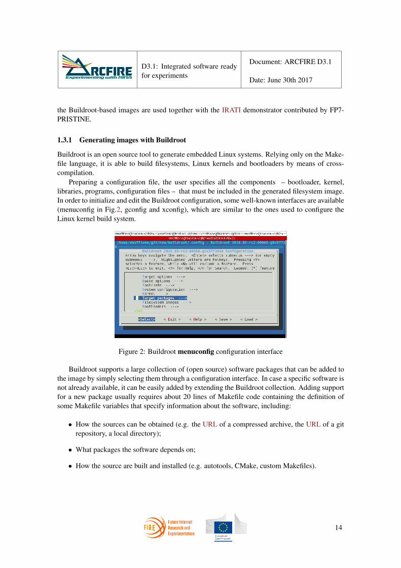
Buildroot is an open source tool to generate embedded Linux systems. Relying only on the Make-file language, it is able to build filesystems, Linux kernels and bootloaders by means of cross-compilation.
Preparing a configuration file, the user specifies all the components – bootloader, kernel,libraries, programs, configuration files – that must be included in the generated filesystem image.In order to initialize and edit the Buildroot configuration, some well-known interfaces are available(menuconfig in Fig.2, gconfig and xconfig), which are similar to the ones used to configure theLinux kernel build system.
Figure 2: Buildroot menuconfig configuration interface
Buildroot supports a large collection of (open source) software packages that can be added tothe image by simply selecting them through a configuration interface. In case a specific software isnot already available, it can be easily added by extending the Buildroot collection. Adding supportfor a new package usually requires about 20 lines of Makefile code containing the definition ofsome Makefile variables that specify information about the software, including:
• How the sources can be obtained (e.g. the URL of a compressed archive, the URL of a gitrepository, a local directory);
• What packages the software depends on;
• How the source are built and installed (e.g. autotools, CMake, custom Makefiles).
14

D3.1: Integrated software readyfor experiments
Document: ARCFIRE D3.1
Date: June 30th 2017
When the user starts the image generation (by issuing the make command), the following stepsare carried out by Buildroot
1. Download the sources of a build toolchain (a compiler, a linker, an assembler, etc.) whichsupports the target architecture. By default, a recent GNU toolchain is selected.
2. Build the toolchain from the downloaded sources.
3. Download the sources for all the packages to be included in the generated image, as specifiedby the configuration file.
4. Use the toolchain to cross-compile all the specified packages, including the basic ones (libc,shell, busybox binutils) and optionally a user-specifed version of the Linux kernel.
5. Pack all the files and binaries resulting from the build into an image. Various file systemformats and compression methods are available.
6. Optionally, overlay a local directory onto the filesystem image. This is useful to add config-uration files, scripts and cryptographic content, which are not included by any package.
1.3.2 Buildroot extensions for IRATI, DMS and rlite
For the purposes of ARCFIRE, Buildroot has been extended with packages containing the IRATI,DMS and rlite software.
Regarding the IRATI software, four packages have been added, corresponding to its sub-packages: modified kernel, librina, rinad and rina-tools. Since the IRATI userspace packagesuse autotools as build system, and autotools is natively supported by Buildroot, the correspondingmakefiles added to the package collection are short and straightfoward. The extensions for IRATIare available at https://github.com/irati/buildroot, in the irati branch. In order toprevent Buildroot from cloning the IRATI repository four times, which may take a very long time,the extensions have been implemented in such a way that only the kernel package triggers the codedownload. The other three packages depend on the first one either directly or indirectly, and justreuse the code locally downloaded by Buildroot.
The irati-dms branch on the same repository contains the DMS extensions in addition tothe IRATI ones, where the DMS java archives are overlaid onto the generated image. Simi-larly, the Buildroot extensions for rlite are available at https://github.com/vmaffione/buildroot, in the rlite branch. A single package is enough to build and install rlite kernel mod-ules and user-space parts, which use the CMake build system, natively supported by Buildroot.
Although the primary purpose of Buildroot is to build images to be flashed to real embeddedsystems – which usually run architectures different from x86 64 – ARCFIRE uses Buildroot in adifferent way. The image is built for the x86 64 architecture, which is assumed to be the same oneused by the developer testbed; other architectures, x86 included, are not worth to be considered. In
15

D3.1: Integrated software readyfor experiments
Document: ARCFIRE D3.1
Date: June 30th 2017
this way, the image can be used by a Virtual Machine, with the near-native performance allowedby hardware assisted virtualisation technologies (i.e. Intel VT-x or AMD-V).
The QEMU hypervisor (http://www.qemu.org) is used as virtualiser. One of the reasonsof choosing QEMU is due to its ability to act as a Linux bootloader: when given a kernel imageand an initial RAM filesystem (initramfs) as command-line arguments, QEMU can directly bootthe specified kernel, which will in turn mount the initramfs and provide a console to the user. Thisis quite different from the traditional way of running Virtual Machines.
Usually, QEMU would be given a disk image as command line argument, the full BIOS diskbootstrap process, with processor running in 16 bits real mode, would be emulated, and the Linuxbootloader would be stored inside the disk image itself.
Conversely, when using QEMU in bootloader mode, no disk image is necessary: the wholefilesystem is stored in the initramfs, which is backed by the VM main memory. For the purposes ofARCFIRE, Buildroot is configured to build the IRATI kernel (or a recent vanilla kernel in the caseof rlite) and generate its image as a cpio-compressed initramfs. This approach has the followingadvantages:
• Skipping the BIOS bootstrap improves boot time (also considering that hardware virtualisa-tion is not available for 16-bit real-mode legacy code).
• The initramfs image is extremely small (approximately 40 MB), when compared to a typicalIRATI VM disk image (4-8 GB). This is due to different reasons:
– The Linux kernel is built with very few drivers: only the ones needed for the QEMUemulated hardware.
– The image does not contain a build toolchain, since everything is built by cross-compilation on the testbed physical machine.
– No bootloader is needed.– Only the software packages that are really needed are included.
• Reduced image generation time, since the Linux kernel builds within 5 minutes when notincluding all the unused driver modules; moreover, building the bootloader is not necessary.
In conclusion, using Buildroot to build IRATI (or rlite) VM images is very convenient for thesoftware verification strategy, with the goal of incrementing the productivity of the developmentprocess:
• The produced images (kernel + initramfs) take less than 40 MB in total, so that it can beeasily shared and by email, git repositories, ftp servers, etc.
• The image creation and update process is fully automated: issuing the make command isenough to trigger the image generation. In particular is not necessary to carry out a buildprocess inside the VM: this only happens on the developer/testbed physical machine.
16

D3.1: Integrated software readyfor experiments
Document: ARCFIRE D3.1
Date: June 30th 2017
• As reported in section 1.3.3, the Buildroot-generated image integrates very well with theIRATI/rlite demonstrator tools.
1.3.3 Demonstrator tools enhanced with Buildroot
The IRATI demonstrator (https://github.com/IRATI/demonstrator) is a tool de-signed and implemented by FP7-PRISTINE, which allows the user to easily try and/or test theIRATI stack in a multi-node scenario. Each node is emulated using a light VM, run under the con-trol of the QEMU hypervisor. All the VM are run on the local machine, so that multiple physicalmachines are not needed.
The demonstrator has two purposes:
• Allow people interested in RINA to easily try using the IRATI stack, even if they know littleabout RINA or IRATI.
• Help IRATI developers and software release engineers to carry out functional and regressiontests.
Given a user-specified network topology (with an arbitrary configuration of DIF), the demon-strator launches all the necessary VM and accesses them to load kernel modules, run IRATI dae-mons, create and configure IPCPs, carry out enrolments, etc. The tool is feature rich: it supportspolicies, link emulation, and more. It can be used to easily test IRATI in a number of differentscenarios. The full documentation is available in the README.md file of the GitHub repository.
However, the original demonstrator released by PRISTINE requires the user to create a cus-tom VM image and manually build and install the IRATI software from within the VM, with allthe drawbacks outlined in section 1.3.2. ARCFIRE instead extended the demonstrator in orderto use it in conjunction with Buildroot to implement its software verification strategy. To makethis possible, the demonstrator has been extended to be able to run VM with QEMU in bootloadermode with Buildroot-generated images, as described in section 1.3.2. The use of traditional cus-tom VM images – referred to as “legacy mode” – is still possible, and useful in some cases 1.However, the new Buildroot mode has now become the default, since it is extremely user friendlyfor both casual users and developers. In fact, Buildroot mode does not require the user to do anypreliminary setup/preparation steps, as a recent snapshot of the Buildroot-generated IRATI kerneland initramfs is already included in the demonstrator repository, and regularly updated. This isparticularly valuable for the dissemination purpose of the tool, as the casual user only needs toclone a GitHub repository to have everything that is needed.
The verification strategy worflow is illustrated in more detail in Figure 3. The user clones thedemonstrator git repository (1) and specifies the desired topology and DIF configurations in the
1For example when deep debugging is necessary, having a regular Linux environment in the VM (with gdb, gprof)is convenient.
17

D3.1: Integrated software readyfor experiments
Document: ARCFIRE D3.1
Date: June 30th 2017
Figure 3: Verification strategy workflow for ARCFIRE: the demonstrator tool.
gen.conf configuration file (2), or just uses the default configuration. At (3), the gen.py scriptis run to generate the up.sh and down.sh shell scripts from the provided configuration. At (4),the up.sh script is run to setup and configure the VM (including IPCP creation, enrolment, etc.).At (5), the user is free to access any node (using the access.sh script) and carry out the tests,running RINA applications and/or playing with the RINA stacks. Once the tests are finished, thenodes are shut down by the down.sh script (6). Then the user can setup again the same scenariowith up.sh (4) or generate a different scenario by modifying the configuration file (2, 3).
After scenario teardown (6), the developer may want to update the RINA stack code to fixbugs or test new feature branches (7). Once the code gets updated (either on the local filesystemor in the remote repository) the Buildroot build process is started to create the updated kernel andinitramfs (8). After that, the developer can setup the scenario again (with the updated images)either with the same configuration (4) or with a new configuration (2, 3).
Although the description reported in this section refers to the IRATI demonstrator, a port of thesame tool is also available for rlite, in the demo/ directory of its GitHub repository. The develop-ment and verification workflow described above is therefore valid also for the rlite demonstrator.
1.3.3.1 Updates to the IRATI demonstrator
The major ARCFIRE contribution to the IRATI demonstrator so far is the integration with Build-root. However, other features have also been developed by T3.4 in addition to that:
• Integration with the netem module[12] of the Linux Traffic Control framework, to supportlink emulation (bandwidth, loss, delay, etc.) for the links between the VM nodes.
18

D3.1: Integrated software readyfor experiments
Document: ARCFIRE D3.1
Date: June 30th 2017
• Support for per-node and per-DIF policies.
• Full support for the security profiles (both default and specific), as defined by the IRATIconfiguration file syntax.
2 Enhancements to the RINA stack implementations
ARCFIRE success depends on the scalability and stability of the available RINA implementa-tions. The main goal of T3.1 is to enhance the IRATI stack inherited from FP7-PRISTINE inorder to support the WP4 large-scale experimentation activites. Several enhancements have beenimplemented: the low level integration of the IRATI stack with the kernel has bee improved, alsoimproving the overall performance of the stack in order to meet the scalability and stability re-quirements are quantified by ARCFIRE Objective 2 (up to 10-100 DIF and 5 levels of DIF depth,up to 100 nodes, up to a week long experiments). On top of that, several new features have beenadded to the IRATI stack, and a POSIX-like API has been implemented in order to ease the require-ments on the developers of RINA applications. The enhancements are described in the followingsections.
2.1 A POSIX-like API for RINA
A fundamental aspect that was not properly addressed in RINA research projects so far is the de-sign of a simple and straightforward API for applications. The C++ API exposed by IRATI librinaproved to be quite tough to use and assimilate, and this is one of the reasons why there are only afew (very simple) native RINA applications. While this is not directly related to thwe scalabilityand stability objectives of ARCFIRE, the development of complex network applications (e.g. webbrowsers and servers, p2p applications, etc.) has the potential to strengthen the enhancement effortthrough missing feature requests and bug reports, and it will greatly improve the experimentationactivities: if the applications are too few and too simple, the experiments are less meaningful andprone to fail when reproduced with real applications. Moreover, the need for a simple and power-ful API also comes from ARCFIRE Objective 3, in terms of benefits for the developers; the QoScapabilities built-in RINA are reflected in the API, so that developers can write (or modify) theirapplications to be QoS-aware.
Since existing network applications are written using the socket API, it comes natural to designa C RINA API which closely resembles the socket API, provided that the differences in the namingand addressing scheme and the QoS support are taken into account. The socket API is currentlydefined by the POSIX.1-2008 standard; for this reason the API presented in this section will bereferred to as a POSIX-like API for RINA.
The advantages of a C POSIX-like API include the following:
• POSIX standards are universally accepted and widely known, so that it would be easy fordevelopers to catch up with the RINA API and start writing applications.
19

D3.1: Integrated software readyfor experiments
Document: ARCFIRE D3.1
Date: June 30th 2017
• The socket API has been introduced more than 30 years ago, and has never been abandoned,proving to be a powerful tool to build the internals of network applications and adapt toupcoming requirements.
• It would be easy to port existing network applications to RINA, starting from the definitionof a simple mapping between socket API calls and RINA API calls.
• File descriptors are used as universal handlers to interact with the API; this makes it pos-sible to reuse standard system calls (e.g. read, write, close, ...), and synchronizationmechanism (e.g. select, poll, ...).
• The C language is widely used for mission-critical network applications, and a C API canalso be used directly by C++ programs.
The RINA API described in sections 2.1.1 and 2.1.2, comes from the original API of the rliteproject [6], where all the interactions with the API were already mediated by file descriptors. T3.1adopted this API and evolved it: (i) the API calls were renamed to be implementation independent;(ii) the missing arguments added where needed; (iii) the API was extended to fully support non-blocking operation. An important goal that was achieved by T3.1 is full API and ABI compatibilitybetween the IRATI and rlite implementations, so that the same applications can be run unmodifiedon any of the two stacks. This compatibility, in particular, made it possible to import into IRATIsome C applications that were originally developed as part of rlite.
2.1.1 API walkthrough
A convenient way to introduce the API is to show how a simple application would use the client-side and server-side API calls. This also eases the comparison with sockets, where a similarwalkthrough is often presented. Note that in this context the term client simply refers to theinitiator of the flow allocation procedure (or TCP connection), while the term server refers tothe other peer. The discussion here, in other words, does not imply that the client/server paradigmmust be applied; the walkthrough is more general, being valid also for other distributed applicationparadigms (e.g. peer-to-peer).
The workflow presented in this subsection, depicted in figure 4, refers to the case of blockingoperation, that is the API calls may block waiting for asynchronous events; moreover, for the sakeof exposition, we assume that the operations do not fail. Non-blocking operations and errors arehowever covered by the API specification(section 2.1.2) and the examples (section 2.1.4).
2.1.1.1 Server-side operations
The first operation needed by the server, (1) in figure 4, is rina open, which takes no argumentsand returns a listening file descriptor (an integer, as usual) to be used for subsequent server-side
20

D3.1: Integrated software readyfor experiments
Document: ARCFIRE D3.1
Date: June 30th 2017
Figure 4: RINA API client and server workflow for blocking operation.
21

D3.1: Integrated software readyfor experiments
Document: ARCFIRE D3.1
Date: June 30th 2017
calls. This file descriptor is the handler for an instance of a RINA control device which acts as areceiver for incoming flow allocation requests.
At (2), the server calls rina register to register a name with the RINA control device,specifying the associated listening file descriptor (lfd), the name of the DIF to register to (dif)and the name to be registered (appl). The DIF argument is optional and advisory: the APIimplementation may choose to ignore it, and use some namespace management strategy to decideinto which DIF the name should be registered.
After a successful registration, the server can receive flow allocation requests, by callingrina flow accept on the listening file descriptor (3). Since the listening file descriptor wasnot put in non-blocking mode, this call will block until a flow request arrives. When this happens,the function returns a new file descriptor (cfd), the name of the remote application (src) and theQoS granted to the flow. The returned file descriptor is an handler for an instance of a RINA I/Odevice, to be used for data I/O.
At this point (4), the flow allocation is complete, and the server can exchange SDU with theclient, using the write and read blocking calls or working in non-blocking mode (possiblymutliplexing with other I/O devices, sockets, etc.) by means of poll or select. This I/O phaseis completely analogous to the I/O exchange that happens with TCP or UDP sockets, only the QoSmay be different.
Once the I/O session ends, the server can close the flow, triggering flow deallocation, using theclose system call (5). The server can then decide whether to terminate or accept another flowallocation request (3).
2.1.1.2 Client-side operations
Client operation is straightforward; the client calls rina flow alloc (1) to issue a flow alloca-tion request, passing as arguments the name of the DIF that is asked to support the flow (dif), thename of the client (src, i.e. the source application name), the name of the destination application(dst, i.e. the server name) and the required QoS for the flow (qos). The call will block until theflow allocation completes successfully, returning an file descriptor (fd) to be used for data I/O.
At this point the client can exchange SDU with the server (2), using the I/O file descriptoreither in blocking or not blocking mode, similarly to what is possible to do with sockets. Whenthe I/O session terminates, the client can deallocate the flow with the close system call.
2.1.2 API specification
In the following, the API calls are listed and documented in depth.Some general considerations:
• The API functions typically return 0 or a positive value on success. On error, -1 is returnedwith the errno variable set accordingly to the specific error.
22

D3.1: Integrated software readyfor experiments
Document: ARCFIRE D3.1
Date: June 30th 2017
• Each application name is specified using a C string, where the name’s components (Applica-tion Process Name, Application Process Instance, Application Entity Name and ApplicationEntity Instance) are separated by the | separator (pipe). The separator can be omitted if itis only used to separate empty strings or a non-empty string from an empty string. Validstrings are for instance "aa|bb|cc|dd", "aa|bb||", "aa|bb", "aa".
int rina_open(void)
This function opens a RINA control device that can be used to register/unregister names,and manage incoming flow allocation requests. On success, it returns a file descriptor that canbe later passed to rina register(), rina unregister(), rina flow accept(), andrina flow respond(). On error -1 is returned with errno set properly. Applications typicallycall this function as a first step to implement server-side functionalities.
int rina_register(int fd,const char *dif,const char *appl,int flags)
This function registers the application name appl to a DIF in the system. After a successfulregistration, flow allocation requests can be received on fd by means of rina flow accept().If dif is not NULL, the system may register the application to dif. However, the dif argumentis only advisory and the implementation is free to ignore it. If DIF is NULL, the system au-tonomously decide to which DIF appl will be registered to.
If RINA F NOWAIT is not specified in flags, this function will block the caller until theoperation completes, and 0 is returned on success.
If RINA F NOWAIT is specified in flags, the function returns a file descriptor (differentfrom fd) which can be used to wait for the operation to complete (e.g. using POLLIN withpoll() or select()). In this case the operation can be completed by a subsequent call torina register wait().
On error -1 is returned, with the errno code properly set.
int rina_unregister(int fd,
23

D3.1: Integrated software readyfor experiments
Document: ARCFIRE D3.1
Date: June 30th 2017
const char *dif,const char *appl,int flags)
This function unregisters the application name appl from the DIF where it was registered to. Thedif argument must match the one passed to rina register(). After a successful unregis-tration, flow allocation requests can no longer be received on fd. The meaning of the RINA F -NOWAIT flag is the same as in rina register(), allowing non-blocking unregistration, to belater completed by calling rina register wait().
Returns 0 on success, -1 on error, with the errno code properly set.
int rina_register_wait(int fd,int wfd)
This function is called to wait for the completion of a (un)registration procedure previously ini-tiated with a call to rina register() or rina unregister on fd which had the RINA -F NOWAIT flag set. The wfd file descriptor must match the one that was returned by rina -[un]register(). It returns 0 on success, -1 error, with the errno code properly set.
int rina_flow_accept(int fd,char **remote_appl,struct rina_flow_spec *spec,unsigned int flags)
This function is called to accept an incoming flow request arrived on fd. If flags does notcontain RINA F NORESP, it also sends a positive response to the requesting application; other-wise, the response (positive or negative) can be sent by a subsequent call to the rina flow -respond(). On success, the char* pointed by remote appl, if not NULL, is assigned thename of the requesting application. The memory for the requestor name is allocated by the calleeand must be freed by the caller. Moreover, if spec is not NULL, the referenced data structure isfilled with the QoS specification specified by the requesting application.
If flags does not contain RINA F NORESP, on success this function returns a file descriptor
24

D3.1: Integrated software readyfor experiments
Document: ARCFIRE D3.1
Date: June 30th 2017
that can be subsequently used with standard I/O system calls (write(), read(), select()...)to exchange SDU on the flow and synchronize. If flags does contain RINA F NORESP, onsuccess a positive number is returned as an handle to be passed to a subsequent call to rina -flow respond(). Hence the code
cfd = rina_flow_accept(fd, &x, flags & ˜RINA_F_NORESP)
is functionally equivalent to
h = rina_flow_accept(sfd, &x, flags | RINA_F_NORESP);cfd = rina_flow_respond(sfd, h, 0 /* positive response */);
On error -1 is returned, with the errno code properly set.
int rina_flow_respond(int fd, int handle, int response)
This function is called to emit a verdict on the flow allocation request identified by handle,that was previously received on fd by calling rina flow accept()with the RINA F NORESPflag set. A zero response indicates a positive response, which completes the flow allocation pro-cedure. A non-zero response indicates that the flow allocation request is denied. In both casesresponse is sent to the requesting application to inform it about the verdict. When the responseis positive, on success this function returns a file descriptor that can be subsequently used withstandard I/O system calls to exchange SDU on the flow and synchronize. When the response isnegative, 0 is returned on success. In any case, -1 is returned on error, with the errno code properlyset.
int rina_flow_alloc(const char *dif,const char *local_appl,const char *remote_appl,const struct rina_flow_spec *flowspec,unsigned int flags);
25

D3.1: Integrated software readyfor experiments
Document: ARCFIRE D3.1
Date: June 30th 2017
This function is called to issue a flow allocation request towards the destination applicationcalled remote appl, using local appl as a source application name. If flowspec is notNULL, it specifies the QoS parameters to be used for the flow, should the flow allocation requestbe successful. If it is NULL, an implementation-specific default QoS will be assumed instead(which typically corresponds to a best-effort QoS). If dif is not NULL the system may look forremote appl in a DIF called dif. However, the dif argument is only advisory and the systemis free to ignore it and take an autonomous decision.
If flags specifies RINA F NOWAIT, a call to this function does not wait until the completionof the flow allocation procedure; on success, it just returns a control file descriptor that can besubsequently fed to rina flow alloc wait() to wait for completion and obtain the flow I/Ofile descriptor. Moreover, the control file descriptor can be used with poll(), select() andsimilar.
If flags does not specify RINA F NOWAIT, a call to this function waits until the flow allo-cation procedure is complete. On success, it returns a file descriptor that can be subsequently usedwith standard I/O system calls to exchange SDU on the flow and synchronize.
In any case, -1 is returned on error, with the errno code properly set.
int rina_flow_alloc_wait(int wfd)
This function waits for the completion of a flow allocation procedure previosuly initiated witha call to rina flow alloc() with the RINA F NOWAIT flag set. The wfd file descriptormust match the one returned by rina flow alloc(). On success, it returns a file descriptorthat can be subsequently used with standard I/O system calls to exchange SDU on the flow andsynchronize. On error -1 is returned, with the errno code properly set.
struct rina_flow_spec {uint64_t max_sdu_gap; /* in \acs{SDU} */uint64_t avg_bandwidth; /* in bits per second */uint32_t max_delay; /* in microseconds */uint16_t max_loss; /* percentage */uint32_t max_jitter; /* in microseconds */uint8_t in_order_delivery; /* boolean */uint8_t msg_boundaries; /* boolean */
26

D3.1: Integrated software readyfor experiments
Document: ARCFIRE D3.1
Date: June 30th 2017
};
void rina_flow_spec_default(struct rina_flow_spec *spec)
This function fills in the provided spec with an implementation-specific default QoS, whichshould correspond to a best-effort QoS. The fields of the rina flow spec data structure specifythe QoS of a RINA flow as follows:
• max sdu gap specifies the maximum number of consecutive SDU that can be lost with-out violating the QoS. Specifying -1 means that there is no maximum, and so the flow isunreliable; 0 means that no SDU can be lost and so the flow is reliable.
• avg bandwidth specifies the maximum bandwidth that should be guaranteed on this flow,in bits per second.
• max delay specifies the maximum one-way latency that can be experienced by SDU ofthis flow without violating the QoS, expressed in microseconds.
• max loss specifies the maximum percentage of SDU that can be lost on this flow withoutviolating the QoS.
• max jitter specifies the maximum jitter that can be experienced by SDU on this flowwithout violating the QoS.
• in order delivery, if true requires that the SDU are delivered in order on this flow (noSDU reordering is allowed).
• msg boundaries: if true, the flow is stream-oriented, like TCP; a stream-oriented flowdoes not preserve message boundaries, and therefore write() and read() system callsare used to exchange a stream of bytes, and the granularity of the exchange is the byte. Iffalse, the flow is datagram-oriented, like UDP, and does preserve message boundaries. TheI/O system calls are used to exchanges messages (SDU), and the granularity of the exchangeis the message.
2.1.3 Mapping sockets API to RINA API
The walkthrough presented in section 2.1.1 and figure 4 highlights the strong relationship betweenthe RINA POSIX API and the socket API. In this section we will explore this relationship indepth, in order to
27

D3.1: Integrated software readyfor experiments
Document: ARCFIRE D3.1
Date: June 30th 2017
• Define a clear mapping from socket calls to RINA calls, that can be used as a referencestrategy to port existing socket applications to RINA; it can never be stressed enough howimportant the availability of real-world applications is to attract people to RINA.
• Highlight the functionalities in the RINA API that are left outside the mapping, as there isno corresponding functionality in the socket API.
The mapping is illustrated separately for client-side operations and server-side ones. More-over, for the sake of simplicity, it refers to Internet sockets, i.e. sockets belonging to the AF INETand AF INET6 family.
Figure 5: Bidirectional mapping between server-side socket API calls to RINA API calls. Thisscheme can be used to port existing socket applications to RINA.
2.1.3.1 Client-side operations
The typical workflow of a TCP or UDP client – w.r.t socket calls – starts by creating a kernel socketwith the socket() system call; the arguments specify the type of socket to be created, i.e. theaddress family (usually internet addresses over IPv4 or IPv6) and the contract with the application(stream-oriented or datagram-oriented socket). The system call returns a file descriptor that ispassed to subsequent API and I/O calls. The client can optionally bind a local name to the socket,that is a name for the local endpoint (e.g. source IP address and/or source UDP/TCP port); thisoperation can be performed with the bind() system call.
Afterwards, the client can specify the name of the remote endpoint (e.g. destination IP addressand destination UDP/TCP port), using the connect() system call. This step is mandatory forTCP sockets since it is also used to perform (or at least initiate) the TCP handshake, whereas it
28

D3.1: Integrated software readyfor experiments
Document: ARCFIRE D3.1
Date: June 30th 2017
is only optional for UDP sockets. A connected UDP socket can be useful when there is a singleremote endpoint, so that the client can use the write(), send(), read() and recv() systemcalls that do not require the address of the remote address as an argument. If multiple endpointsare possible (and the the client does not want to use multiple connected UDP sockets) a singlenot-connected socket can be used with the sendmsg, sendto, recvmsg, recvfrom variantsto specify the address of the remote endpoint at each I/O operation.
If the socket file descriptor is set in non-blocking mode, the connect() system call on aTCP socket will not block waiting for the TCP handshake to complete, but return immediately;the client can then feed the file descriptor to select() (or poll()) waiting for it to becomewritable, and when this happens it means that the TCP handshake is complete. Once the client-sideoperations are done, I/O can start with the standard I/O system calls (write, read) or socket-specific ones (recv(), send(), ...). When the session ends, the client closes the socket withclose().
The corresponding client-side operations can be done with the RINA API through rina -flow alloc and rina flow alloc wait. In detail, rina flow alloc replaces thesocket(), bind() and connect() calls:
• The name of the local endpoint is specified by the local appl argument.
• The name of the remote endpoint is specified by the remote appl argument.
• The return value is a file descriptor that can be used for flow I/O, so that there is no need fora specific call to create the file descriptor (like socket()).
The non-blocking connect functionality is supported by passing the RINA F NOWAIT flagto rina flow alloc; when this happens, the function does not wait for flow allocation tocomplete, but returns a control file descriptor that can then be used with select/poll to wait;when the control file descriptor becomes readable, it means that the flow allocation procedure iscomplete and the client can call rina flow alloc wait to receive the I/O file descriptor.
This analysis outlines the capabilities that the RINA API offers and that are not availablethrough the socket API:
• In RINA the client can optionally specify the layer (i.e. the DIF) where the flow allocationshould happen, while with sockets the layer is implicit.
• In RINA the client can specify the QoS required for the flow.
• RINA has a complete naming scheme that is valid for any network application, whereassockets have multiple families with different (incomplete) naming schemes like IPv4 +TCP/UDP, IPv6 + TCP/UDP, etc.
29

D3.1: Integrated software readyfor experiments
Document: ARCFIRE D3.1
Date: June 30th 2017
2.1.3.2 Server-side operations
Server-side socket operations start with the creation of a socket to be used to listen for incomingrequests. Similarly to the client, this is done with the socket system call and the returned filedescriptor is used for subsequent operations. The server then binds a local name to the socket,using the bind() system call; differently from the client case, this step is mandatory, as the servermust indicate on what IP address and ports it is available to receive incoming TCP connectionsor UDP datagrams. If the socket is UDP, at this point the server can start receiving and sendingdatagrams, using the recvfrom, recvmsg, sendto and sendmsg system calls. It couldalso optionally bind a remote name with connect(), if it is going to serve only a client (theconsiderations about connected UDP sockets reported in Section 2.1.3.1 are also valid here).
If the socket is TCP, the server needs to call the listen() system call to indicate that isgoing to accept incoming TCP connection on the address and port bound to the socket, indicatingthe size of the backlog queue as a parameter. This operation puts the socket in listening mode.Afterwards, the server can invoke the accept() system call to wait for the next TCP connectionto come from a client. The accept() function returns a new file descriptor and the name ofthe remote endpoint (that is the address and port of the client). The file descriptor can then beused to perform the I/O with the client, using read(), write(), send(), recv(), etc., andpossibly using I/O multiplexing (select and poll). Moreover, if the listening socket is set innon-blocking mode, the server can use select() or poll() to wait for the socket to becomereadable, which indicates a new TCP connection has arrived and can be accepted with accept().When the I/O session ends, the server closes the client socket with close().
Similar server-side operations can be performed with the RINA API. A RINA control deviceto receive incoming flow requests is opened with rina open, similarly to the socket() call.This function returns a file descriptor that can be used to register names and accept requests. Therina register function is called to register an application name, possibly specifying a DIFname; the control file descriptor is passed as a first parameter, so that the file descriptor can beused to accept requests for the registered name. The rina register operations correspondstherefore to the combined effect of bind and listen for sockets. It is possible to call rina -register multiple times to register multiple names.
At this point the server can start accepting incoming flow allocation requests by calling rina -flow accept on the control file descriptor (passed as first argument). When the RINA F -NOWAIT flag is not specified, this operation has the same meaning of the socket accept call. Indetail:
• The function blocks until a flow allocation request comes, and the request is implicitelyaccepted.
• A file descriptor is returned to be used for flow I/O.
• The name of the remote application can be obtained through the remote appl outputargument.
30
D3.1: Integrated software readyfor experiments
Document: ARCFIRE D3.1
Date: June 30th 2017
• The QoS of the new flow (specified by the remote application) can be obtained through thespec output argument.
Non-blocking accept is also possible, since the control file descriptor can be set in non-blockingmode and passed to poll/select. The control file descriptor becomes readable when there is apending flow allocation request ready to be accepted.
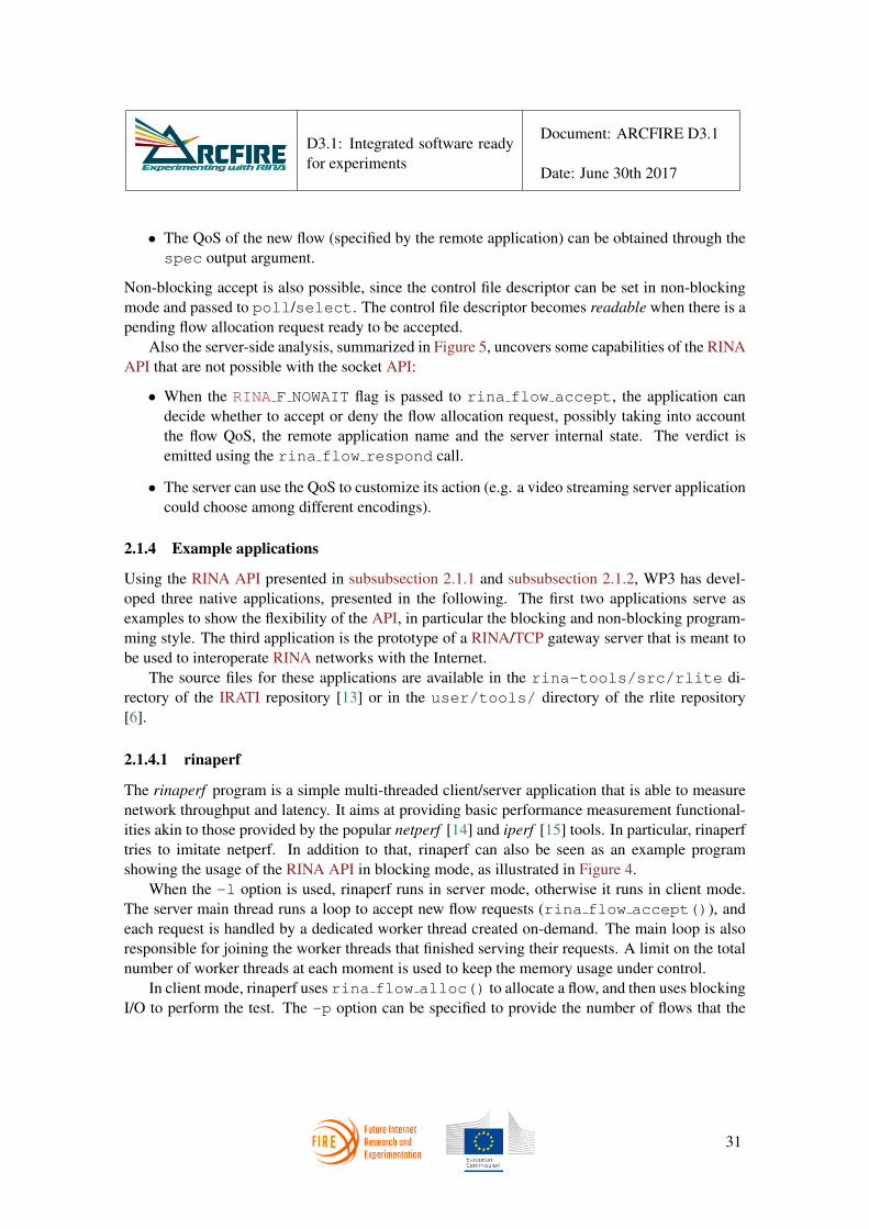
Also the server-side analysis, summarized in Figure 5, uncovers some capabilities of the RINAAPI that are not possible with the socket API:
• When the RINA F NOWAIT flag is passed to rina flow accept, the application candecide whether to accept or deny the flow allocation request, possibly taking into accountthe flow QoS, the remote application name and the server internal state. The verdict isemitted using the rina flow respond call.
• The server can use the QoS to customize its action (e.g. a video streaming server applicationcould choose among different encodings).
2.1.4 Example applications
Using the RINA API presented in subsubsection 2.1.1 and subsubsection 2.1.2, WP3 has devel-oped three native applications, presented in the following. The first two applications serve asexamples to show the flexibility of the API, in particular the blocking and non-blocking program-ming style. The third application is the prototype of a RINA/TCP gateway server that is meant tobe used to interoperate RINA networks with the Internet.
The source files for these applications are available in the rina-tools/src/rlite di-rectory of the IRATI repository [13] or in the user/tools/ directory of the rlite repository[6].
2.1.4.1 rinaperf
The rinaperf program is a simple multi-threaded client/server application that is able to measurenetwork throughput and latency. It aims at providing basic performance measurement functional-ities akin to those provided by the popular netperf [14] and iperf [15] tools. In particular, rinaperftries to imitate netperf. In addition to that, rinaperf can also be seen as an example programshowing the usage of the RINA API in blocking mode, as illustrated in Figure 4.
When the -l option is used, rinaperf runs in server mode, otherwise it runs in client mode.The server main thread runs a loop to accept new flow requests (rina flow accept()), andeach request is handled by a dedicated worker thread created on-demand. The main loop is alsoresponsible for joining the worker threads that finished serving their requests. A limit on the totalnumber of worker threads at each moment is used to keep the memory usage under control.
In client mode, rinaperf uses rina flow alloc() to allocate a flow, and then uses blockingI/O to perform the test. The -p option can be specified to provide the number of flows that the
31

D3.1: Integrated software readyfor experiments
Document: ARCFIRE D3.1
Date: June 30th 2017
client is asked to allocate in parallel. Each flow is allocated and handled by a dedicated thread. Thedefault value for the -p option is 1, so that by default rinaperf allocates only one flow (using themain thread). The client can specify various options to customize the performance test, includingthe number of packets to send (or transactions to perform), the packet size, the flow QoS, the DIFto use, the inter-packet transmission interval, the burst size, etc.
To date, three test types are supported:
• ping, implementing a simple ping functionality for quick connectivity checks.
• perf, which provides an unidirectional throughput test, similar to netperf UDP STREAM orTCP STREAM tests.
• rr, which measures the average latency of request/response transactions, similar to netperfTCP RR or UDP RR tests.
For both client and server, each thread manages the I/O for a single flow, blocking on the I/Ocalls when necessary. Concurrency is therefore achieved by means of multithreading. Runningrinaperf with the -h option will list all the available options.
As an example, the following rinaperf invocation will perform request-response tests with amillion transactions of 400 bytes packets:
user@host ˜/rina # rinaperf -c 1000000 -t rr -s 400Starting request-response test; message size: 400, number of
messages: 1000000, duration: infTransactions Kpps Mbps Latency (ns)
Sender 1000000 145.569 465.821 6869
while the following performs a five seconds long undirectional throughput test with 1460 bytespackets:
user@host ˜/rina # rinaperf -t perf -s 1460 -D 5Starting unidirectional throughput test; message size: 1460,
number of messages: inf, duration: 5 secsPackets Kpps Mbps
Sender 6790377 1358.417 15866.311Receiver 5037989 988.051 11540.436
32

D3.1: Integrated software readyfor experiments
Document: ARCFIRE D3.1
Date: June 30th 2017
2.1.4.2 rina-echo-async
The rina-echo-async program is a single-threaded client/server application that implements anecho service using only non-blocking I/O. Differently from rinaperf, rina-echo-async is meant tobe used for functional testing only; nevertheless, it is a compact educational example that showsall the features of the RINA API in non-blocking mode.
When the -l option is used, rinaperf runs in server mode, otherwise it runs in client mode.Both client and server are able to manage multiple flows in parallel, using a single thread andwithout blocking on allocation, registration, accept or I/O. To achieve concurrency with a singlethread, the program is structured as an event-loop that manages an array of state machines. Theclient state machine is illustrated in Figure 6. The edges in the graph show the pre-conditions forthe state transition (if any) and the actions to be performed when the transition happens. Aftercompleting the flow allocation, the client writes a message to the server and receives the echoedresponse coming back. In client mode, rina-echo-async keeps an array of independent client statemachines, to handle multiple concurrent echo sessions. The -p option can be used to specify howmany flows (sessions) to create and handle; by default, only a single flow is created.
Figure 6: Client state machine for rina-echo-async. Edge labels show preconditions (if any) andactions associated to each state transition.
The server state machines are illustrated in Figure 7. After completing the registration, theserver starts accepting new sessions, denying them if the number of ongoing sessions grows be-yond a limit (128 in the current implementation). A new state machine is created for each acceptedsession. The server therefore manages two types of state machines: one to accept new requests(top of Figure 7), and the other one to serve a single client (bottom of Figure 7). There is oneinstance of the first kind and multiple instance of the second, one per client. The per-client statemachine just receives the echo request and sends the echo response back to the client.
33

D3.1: Integrated software readyfor experiments
Document: ARCFIRE D3.1
Date: June 30th 2017
Figure 7: Server state machine for rina-echo-async. On the top the state machine to accept newclient sessions, on the bottom the one to handle a single session.
2.1.4.3 rina-gw
The rina-gw program is a C++ daemon that acts as a proxy/gateway between a TCP/IP network anda RINA network, as depicted in Figure 8. On the one side, the gateway accepts TCP connectionscoming from a TCP/IP network and proxies them by allocating RINA flows towards the properserver applications in the RINA network. On the other side, the gateway accepts flow allocationrequests coming from the RINA network and proxies them to a TCP server by means of new TCPconnections.
The proxy needs therefore to be configured with a mapping between TCP/IP names (IP andports) and RINA names (DIF and application names). In the current prototype, the mappingcan be specified only with a configuration file that rina-gw reads at startup; future versions mayimplement a mechanism to allow for dynamic reconfiguration. Each line in the configuration filespecifies a single mapping. Two types of mappings are possible, one for each direction: an I2Rdirective maps TCP clients to RINA servers, whereas an R2I directive maps RINA clients to TCPservers.
In the following configuration file example
I2R serv.\acs{DIF} rinaservice2 0.0.0.0 9063R2I vpn3.\acs{DIF} tcpservice1 32.1.42.190 8729
the first directive cofigures rina-gw to proxy incoming connections on destination port 9063 (onany host interface) towards the rinaservice2 application running in serv.DIF; the second directiveasks rina-gw to proxy incoming flow allocation requests for the destination application tcpservice1(on DIF vpn3.DIF) towards a TCP server on host 32.1.42.190 on port 8279.
34

D3.1: Integrated software readyfor experiments
Document: ARCFIRE D3.1
Date: June 30th 2017
Figure 8: The rina-gw deamon used for interoperability between RINA networks and TCP/IPbased networks. TCP connections are proxied over RINA flows and the other way around.
The rina-gw program has been designed as a multi-threaded event-loop based application.The RINA API is used in non-blocking mode together with the socket API. The main threadevent-loop is responsible for the TCP connection setup and RINA flow allocation, while the dataforwarding – i.e. reading data from a TCP socket and writing it on a RINA flow and the otherway around – happens within dedicated worker threads. It is worth observing that the only datastructure that worker threads use is a map that maps each file descriptor into another file descriptor(e.g. std::map<int, int>). As a consequence, the worker thread is generic code that isnot aware of what kind of network I/O is using – TCP sockets, RINA flows, or others. Thistransparency property is possible because of the file descriptor abstraction provided by the newRINA API. In the current prototype, only a single worker thread is used to handle all the activesessions; future versions are expected to use multiple worker threads to scale up with the numberof sessions.
At startup, the main thread reads the configuration file and issues all the bind()/listen()and rina register() calls that are necessary to listen for incoming TCP connection (I2R) orRINA incoming flow requests (R2I). The main poll-based event-loop waits for any of the fourevent types that can happen:
• A flow allocation request comes from the RINA network, matching one of the R2I directives.A TCP connection is initiated towards the mapped IP and port, calling connect() in non-blocking mode.
• A TCP connection comes from the TCP/IP network, matching one of the I2R directives.A RINA flow allocation is initiated towards the mapped DIF and application name, usingrina flow alloc() with the RINA F NOWAIT set.
35

D3.1: Integrated software readyfor experiments
Document: ARCFIRE D3.1
Date: June 30th 2017
• A flow allocation response comes, matching one of the proxied TCP connections associatedto an I2R directive. The rina flow alloc wait() function is called to complete theflow allocation and the new session is dispatched to a worker thread.
• A TCP connection handshake completes for one of the proxied flow allocations associatedto an R2I directive. The new session is is dispatched to a worker thread.
The main event-loop uses some data structures to keep track of the ongoing connection setups.
2.1.5 Updates to the IRATI implementation
Several modifications have been made on the IRATI software in order to provide an implementa-tion of the RINA API described in subsubsection 2.1.2. As full API and ABI compatibility withthe rlite software is necessary and desirable, some design decision were partially reused from thelatter project.
From a high level perspective, the following IRATI subsystems have been affected:
• The IRATI kernel-space code has been extended to expose a virtual character I/O device(/dev/irati), used for application I/O through file descriptors.
• Librina has been modified to manage the character device and to expose the new API bymeans of an additional rina-api library
• All the example applications and tools included in rinad and rina-tools have been modifiedto use the character device for the I/O.
2.1.5.1 Modifications to kernel code
Since the inception of the IRATI software, I/O operations on RINA flows have been supportedthrough ad-hoc system calls, i.e. sdu write to send a SDU and sdu read to receive. Incontrast, with the new RINA API, the I/O operations are supported through the standard POSIXfile system calls, i.e. write to send a SDU and read to receive. Since write and read use afile descriptor to interact with an object in the kernel, IRATI-specific virtual character device hasbeen introduced for that purpose.
Serial ports and physical terminals are examples of physical character devices, that can beaccessed from user-space applications by means of the usual POSIX file descriptor system calls.They are referred as “physical” because the kernel device object instance with which applicationsinteract is backed by a real piece of hardware. In contrast, a virtual device is not backed by aphysical device, but it is just a way to expose a software service (in this case the I/O on a RINAflow) through the standard system calls.
The IRATI device is registered to the kernel as soon as IRATI kernel support is initialized,and the registration triggers the creation of a special device file (/dev/irati) in the file system.
36

D3.1: Integrated software readyfor experiments
Document: ARCFIRE D3.1
Date: June 30th 2017
/dev/irati is a cloning device 2, which means that each open on /dev/irati creates anew, independent kernel object instance that application can use. This is opposed to non-cloningdevice like serial ports, disk partitions and terminals, where independent open calls on the samedevice file result into application interacting with the same kernel object (and the same backingphysical device).
The IRATI character device implements the following file operations (or methods):
• open. Allocate an independent instance associated to the open file. Initially, this instanceis unusable, because it is not bound to any RINA flow.
• ioctl. Bound the device instance to the RINA flow identified by the port-id passed as thirdargument. The flow must be already allocated (i.e. using the librina legacy flow allocationAPI).
• poll. Poll the RINA flow bound to the device, in order to check whether the flow isreadable and/or writable. If the flow is writable, new SDU can be sent, and the POLLOUTbit is set in the returned mask. If the flow is readable, one or more SDU are availableto be received and the POLLIN bit is set in the returned mask. POLLIN is set when thereceive queue for the flow in the kernel IPCP is not empty. This method supports the poll,select and epoll system calls.
• write. Send a SDU through the bound flow. The code previously used for the sdu writesystem call is reused.
• read. Read a SDU from the bound flow. The code previously used for the sdu readsystem call is reused.
• release. Deallocate the device instance, deallocating the bound flow if necessary.
The old I/O system calls sdu write and sdu read have been removed; also the newerflow io ctl system call has been removed, as the corresponding functionality can be imple-mented by means of the standard fcntl.
2.1.5.2 Modifications to librina
The librina library has been modified to make use of the /dev/irati character device by open-ing a device instance for each RINA flow and carring out the binding, as illustrated in Figure 9.
The librina::FlowInformation class has been extended with a fd integer field, usedto store the file descriptor of the /dev/irati instance associated to the flow. Once the flowallocation is completed, the flow port-id is known and the ioctl system call is used to bind the
2using FreeBSD terminology, e.g. https://www.freebsd.org/doc/handbook/network-bridging.html
37

D3.1: Integrated software readyfor experiments
Document: ARCFIRE D3.1
Date: June 30th 2017
file descriptor (i.e. the character device instance) to the port-id. In detail, this operation is per-formed by IPCManager::commitPendingFlow() on the source side of the flow allocationprocedure, and by IPCManager::allocateFlowResponse() on the destination side.
Figure 9: Interations between IRATI librina and the /dev/irati virtual character device.
Since the RINA API allows for standard system calls to be used directly, the IPCManager::-readSDU() and IPCManager::writeSDU()methods were removed in favour of write()and read(). Finally, librina calls the close system calls on the device file descriptor at flowdeallocation time; this happens in IPCManager::flowDeallocationResult() for localdeallocation and in IPCManager::flowDeallocated() for remote deallocation.
Finally, a new rina-api shared object (part of the librina package) has been implemented tosupport all the API calls documented in section subsubsection 2.1.2. The calls are implemented bymeans of the original librina API for application registration and flow allocation. The control filedescriptor returned by rina open() is a clone (obtained by dup()) of the eventfd associatedto the librina internal event queue. The eventfd is a Linux-specific functionality, that can be usedby two threads or processes to exchange notifications using the standard file API; it is basicallya form of semaphore, where a read corresponds to a wait operation on the semaphore, whereasa write corresponds to a post operation. A notification is sent by the librina netlink readerthread every time it pushes a librina event in the queue. When an event is popped from the queue(in response to the librina API calls), the eventfd is automatically drained (by read) to clearthe notification. As a result, the application can use poll() or select() with the controlfile descriptor in order to wait for librina events to happen, i.e. registration or flow allocationto complete. This is fundamental to support applications requiring non-blocking operation, like
38

D3.1: Integrated software readyfor experiments
Document: ARCFIRE D3.1
Date: June 30th 2017
rina-gw and rina-echo-async (subsubsection 2.1.4).
2.1.5.3 Modifications to rinad and rina-tools
A few modifications to the IRATI rinad and rina-tool packages were necessary in order to replaceall the usages of the old IPCManager::readSDU() and IPCManager::writeSDU()withread and write, i.e. in rina-echo-time, CDAP connector, IPCM flow manager and thetoy manager. The old applications have not been converted to the new API (e.g. in registrationand flow allocation), as they are obsoleted by the new example applications described in sub-subsection 2.1.4; moreover, it may be still usefult to keep track of usages of the original librinaAPI.
2.2 Improved integration with the network device layer
2.2.1 A performance issue
The original packet management implemented in IRATI was a very basic and rudimentary solu-tion developed at the beginning of the project, with nearly no changes until ARCFIRE. With thissolution, many operations on the packet used to require different memory allocations, dealloca-tions and data copies, repeated at every layer of the DIF stack. On top of the low performanceof the network stack, this could lead to the inability of delivering the advertised QoS, and servicefailures, especially in large networks such as the ones targeted by ARCFIRE objective 2. Thiswas a consequence of three major flaws in the initial design, justified by the goal to achieve theminimum I/O functionality as quickly as possible:
1. The lack of functionalities to work with contiguous buffers that could be resized without theneed of reallocating memory.
2. The need of an extra step to serialize/deserialize a Protocol Data Unit (PDU) to/from aSDU every time it leaves/enters a DIF to/from a DIF below. This is a consequence ofthe fact that the size of each Protocol Control Information (PCI) field is configurable forevery DIF, i.e. the addresses for a DIF could be 4 bytes long, while in the N-1 DIF theycould be 2 bytes. The PCI was represented as a struct with fields big enough to handle allthe possible cases, and not optimized in space, for example, using C unions. Therefore,this PCI struct did not represent the real PCI wire format that needs to be sent to the N-1DIF. For this reason, each PDU needed a translation (to a SDU) across the north-bound orsouth-bound boundary towards another DIF (or the application). This translation consistedinto a serialization according to the PCI wire format of the source DIF, and a subsequentdeserialization according to the PCI wire format of the target (upper or lower) DIF.
3. When user-space applications wrote some data to a flow, the data was encapsulated andinterpreted differently depending on the stage the packet was going through when traversing
39

D3.1: Integrated software readyfor experiments
Document: ARCFIRE D3.1
Date: June 30th 2017
the DIF. As an example, an SDU containing only the user payload was treated differentlyfrom a PDU containing the user payload plus the additional DIF PCI. Although very similar,both PDU and SDU were represented with different data structures and required differentAPI. The lack of a common data model capable to handle the different cases resulted in theneed of memory allocations, deallocations and copy all throughout the code-path from theuser-space application down to the lowest-level DIF.
In order to fix these three flaws, the WP3 team decided to redesign the IRATI buffer manage-ment subsystem to represent the different RINA Data Units (DU) using the Linux sk buffs, asexplained in the following sections.
2.2.2 Overview of Linux Networking subsystem
Most of the Linux code, including the networking subsystem, widely uses the Object-Oriented(OO) paradigm, although the C language does not directly support OO constructs. In particular, Cstructs are used to represent (abstract and concrete) classes, and overridable methods are imple-mented by means of an explicit virtual function table (vtable) contained in a field of the struct. Thevtable is another struct containing a set of function pointers that reference the actual implementa-tion of the methods. The first argument of these functions is generally a pointer to an instance ofthe struct representing the class (i.e. the object), so that the state of the object itself can be altered.Inheritance is implemented by embedding (or referencing by pointer) the base class struct insidethe derived class struct.
The most important objects in the Linux networking subsystem:
• The network interface, implementing the routines to configure the NIC, and send/receivepackets. A network interface is represented by the struct net device and it can beused for physical devices (Ethernet NIC) or pure software devices like loopback devices andthe TAPs. In IRATI, the struct net device is referenced by the Shim Ethernet IPCPin order to send and receive packets to/from the NIC. The native IRATI object that performsa similar task between IPCP is the struct rmt n1 port, which is used to send andreceive data to/from an upper/lower IPCP.
• The protocol, implementing the the packet header format and connection state machinesassociated to a particular network protocol (e.g. IP, TCP, UDP, . . . ). The Protocol providesservices to the upper Socket layer. A new protocol family can be implemented by defininga new struct proto and struct net proto family. In IRATI, the unique pro-tocol used in RINA, EFCP is implemented jointly by the struct efcp, struct dt,struct dtp and struct dtcp.
• The socket, that implements a communication endpoint to be used by an user-space applica-tion to perform network I/O. The application uses and file descriptor to access the socket. In
40

D3.1: Integrated software readyfor experiments
Document: ARCFIRE D3.1
Date: June 30th 2017
the kernel, each socket is represented as an instance of the struct socket, that imple-ments the high level socket API by means of the lower level protocol interface. The currentversion of IRATI (see subsection 2.1) supports a new POSIX-like API designed for RINA,which provides a similar behaviour.
• The packet buffer, which represents a network packet with data and metadata. All the packetbuffers in the networking subsystem are objects of type struct sk buffs, commonlyreferenced to as skb in the kernel code. The struct sk buffs provides general buffer-ing and flow control facilities needed by all network protocols. So far, IRATI used a veryrudimentary and inefficient mechanism to deal with network packets buffering, which isnot appropriate for the purposes of ARCFIRE. This motivated a code refactor in order toachieve a better integration with Linux’s sk buffs to take advantage of its properties andreduce the number of expensive data copies.
2.2.3 The new SDU/PDU/PCI data model and API
One of the main IRATI design decisions was to completely hide the internal layout and implemen-tation of all the objects (e.g. PCI, SDU, PDU) and provide ad hoc API to let them interoperate.This strategy is not usually followed by most of the Linux kernel code, where the layout of Cstructs used by different modules is shared. However, in order to minimize the changes required toIRATI, the integration with the sk buff layer has been carried out trying to preserve the existingAPI as much as possible.
To address these limitations, the original struct buffer (Figure 10) has been replacedby a struct sk buff. IRATI’s struct buffer and its API were not flexible enough toallow dynamic payload resizing without allocating a new data structure to be filled in by copy. Asdiscussed above, the sk buff data structure is specifically designed to be used by the networkstack for packet memory management. It contains various metadata (including transport, networkand MAC headers) and a block of memory of variable length. The API provided by the sk bufflibrary consists of several routines to manage doubly linked lists of sk buffs and manipulatethe metadata an content of the sk buffs in various ways. As an example, adding or removingdata at the beginning or the end of a packet buffer are common network processing operations,that are supported by means of a set of four pointers to the buffer memory, as shown in Figure 10.The use of Linux sk buff covers the first flaw (see above), at the cost of a minor extra spaceoverhead for the PDU/SDU objects, as the sk buff carries many metadata fields that are neverused within IRATI. Moreover, reusing the sk buff paves the way for the implementation offuture fragmentation and reassembly functionalities, which are already supported by Linux.
To address the second flaw, the original struct pci has been replaced by a simpler objectthat contains (i) the length of the PCI; and (ii) a pointer to the beginning of the PCI header, whichis stored in the sk buff internal buffer. Most of the PCI API provides a set of methods to get/setthe different fields of the PCI directly from/to the memory allocated in the skb, taking into account
41

D3.1: Integrated software readyfor experiments
Document: ARCFIRE D3.1
Date: June 30th 2017
Figure 10: Original IRATI buffer and SKB layout
the configurable size of the various PCI fields. These methods are implemented with two simple Cpreprocessor macros (shown in Listing 1): a precomputed array is used as a lookup table to fetchthe offset of a specific PCI field inside the PCI header. The array is indexed by a set of uniqueidentifiers (a C enum) for the different PCI fields. The lookup table is computed once, during theIPCP process creation and stored in the struct efcp config. The rest of the PCI API isdescribed below.
Figure 11: Original and new IRATI pci
address_t pci_destination(const struct pci *pci){PCI_GETTER(pci, PCI_BASE_DST_ADD, address_length, address_t);}EXPORT_SYMBOL(pci_destination);
int pci_destination_set(struct pci *pci, address_t dst_address)
42

D3.1: Integrated software readyfor experiments
Document: ARCFIRE D3.1
Date: June 30th 2017
{PCI_SETTER(pci, PCI_BASE_DST_ADD, address_length, dst_address);}
EXPORT_SYMBOL(pci_destination_set);
Listing 1: PCI getters/setters API
ssize_t *pci_offset_table_create(struct dt_cons *dt_cons);
Computes the offsets lookup table for each field of the struct pci, according to the PCI fieldsizes specified by dt cons, returning a pointer to an array of ssize t.
bool pci_is_ok(const struct pci *pci);
Returns true if pci is well formed, and false otherwise.
ssize_t pci_calculate_size(struct efcp_config *cfg,pdu_type_t type);
Returns the total size of a struct pci for a given PDU type (e.g. DT PDU, control PDU)according to the DIF configuration specified by cfg.
The third and last flaw has been addressed by defining a struct du type to be used as a“base class” for the subclasses struct pdu and struct sdu. This enables code re-use andhomogenization for the PDU and SDU objects, while at the same time preserving the originalAPI, that require a type of object or the other. The old and new data model for these objects areshown in Figure 12. The new layout for struct du shows how the struct buffer has beenreplaced by the struct sk buff.
As described in subsubsection 2.2.4 and subsubsection 2.2.5, a PDU can be converted to anSDU (or the other way around) by means of a simple type-casting and a proper initializationof the internal fields of the struct du. In contrast, the previous implementation required theallocation of new structures and a buffer copy. In any case, these conversion operations are hiddenby the API.
Figure 13 depicts the data model illustrated in this section, with the new SDU and a PDU, bothbased on the struct du. The corresponding API is shown in Listing 2.2.3.
struct sdu *sdu_create(size_t data_len);struct sdu *sdu_create_ni(size_t data_len);
43

D3.1: Integrated software readyfor experiments
Document: ARCFIRE D3.1
Date: June 30th 2017
Figure 12: Original and new SDU and PDU data models
Figure 13: SDU and PDU data models based on common struct du.
struct sdu *sdu_from_buffer_ni(void *buffer);bool is_sdu_ok(const struct sdu *sdu);int sdu_destroy(struct sdu * sdu);
The sdu create() and sdu create ni() functions allocate an instance of struct sduwith room for MAX PCIS LEN + data len + MAX TAIL LEN bytes, that initially containnot data. While sdu create() can be run in interruptible context, sdu create ni() can-not. The sdu from buffer ni() function allocates a sdu and initialises it with the objectreferenced by buffer, which must be an instance of sk buff in the current implementation;this function can be called in atomic context. is sdu ok() returns true if sdu is valid, falseotherwise. sdu destroy() destroys a sdu object, freeing the associated memory.
unsigned char *sdu_buffer(const struct sdu *sdu);
44

D3.1: Integrated software readyfor experiments
Document: ARCFIRE D3.1
Date: June 30th 2017
ssize_t sdu_len(const struct sdu *sdu);
sdu buffer() returns a pointer to the internal buffer of sdu, while sdu len() returns thebuffer size.
void sdu_attach_skb(struct sdu *sdu, struct sk_buff *skb);struct sk_buff *sdu_detach_skb(const struct sdu *sdu);int sdu_efcp_config_bind(struct sdu *sdu,
struct efcp_config *cfg);
sdu attach skb() binds a skb to sdu, while sdu detach skb() unbinds and returns it.sdu efcp config bind() binds an EFCP configuration (cfg) to sdu; this is used to specifythe data transfer constants to be used for PCI serialization and deserialization.
struct sdu *sdu_from_pdu(struct pdu *pdu);
This function converts pdu into a sdu, returning a pointer to the latter, with the four internalpointers initialized accordingly. The pdu pointer passed as an argument cannot be used anymore.
int sdu_shrink(struct sdu *sdu, size_t bytes);int sdu_pop(struct sdu *sdu, size_t bytes);int sdu_push(struct sdu *sdu, size_t bytes);
These functions are used by different Shim IPCPs, to trim bytes bytes from the end, trim bytesbytes from the the beginning and prepend bytes bytes at the beginning of the internal buffer,respectively.
struct pdu *pdu_create(pdu_type_t type,struct efcp_config *cfg);
struct pdu *pdu_create_ni(pdu_type_t type,struct efcp_config *cfg);
bool pdu_is_ok(const struct pdu *pdu);int pdu_destroy(struct pdu *pdu);
The first two functions create a pdu of type type with a data buffer of size MAX PCIS LEN +MAX TAIL LEN, binding the EFCP configuration cfg; pdu create ni() can be run in atomiccontext, while pdu create() cannot. pdu is ok returns true if pdu is well formed, falseotherwise. pdu destroy() destroys a pdu object, freeing the associated memory.
45

D3.1: Integrated software readyfor experiments
Document: ARCFIRE D3.1
Date: June 30th 2017
struct pdu *pdu_from_sdu(struct sdu *sdu);
This function converts sdu into a pdu, returning a pointer to the latter, with the four internalpointers initialized accordingly. The sdu pointer passed as an argument cannot be used anymore.
const struct pci *pdu_pci_get_ro(const struct pdu *pdu);struct pci *pdu_pci_get_rw(struct pdu *pdu);
These two functions return a pointer to the struct pci contained in the pdu with read-only orread-write permission, respectively.
int pdu_encap(struct pdu *pdu, pdu_type_t type);
pdu encap() computes the size of a PCI of type type and pushes it at the beginning of thepdu’s data buffer. The internal pointer to the PCI header is updated to point to the beginning of thedata buffer. The PCI can then be retrieved with pdu pci get ro() or pdu pci get ro() tobe inspected or modified.
int pdu_decap(struct pdu *pdu);
pdu decap() pops the PCI from the beginning of the data buffer without invalidating the in-ternal pointer to the PCI, which can be retrieved with pdu pci get ro() or pdu pci get -ro().
struct pdu *pdu_dup(const struct pdu *pdu);struct pdu *pdu_dup_ni(const struct pdu *pdu);
These two functions (available for atomic and non-atomic contexts) can be used to clone a pduobject; they return a pointer to the cloned object. With a clone operation, a new instance ofstruct pdu is allocated and initialized from the original one, but both point to the same internalbuffer.
unsigned char *pdu_buffer(const struct pdu *pdu);ssize_t pdu_data_len(const struct pdu *pdu);ssize_t pdu_len(const struct pdu *pdu);
46

D3.1: Integrated software readyfor experiments
Document: ARCFIRE D3.1
Date: June 30th 2017
pdu buffer() returns a pointer to the pdu’s data buffer. pdu data len() returns the sizeof the data payload only (e.g. the size of the encapsulated SDU), while pdu len() returns thesize of the whole PDU (SDU and PCI).
int pdu_sdup_head_set(struct pdu *pdu, void *header);int pdu_sdup_tail_set(struct pdu *pdu, void *tail);void *pdu_sdup_head(struct pdu *pdu);void *pdu_sdup_tail(struct pdu *pdu);
Setters and getters for the SDU Protection fields. header and tail are pointers to the positionin the pdu data buffer of the SDU Protection head and tail, respectively.
int pdu_tail_grow(struct pdu *pdu, size_t bytes);int pdu_tail_shrink(struct pdu *pdu, size_t bytes);int pdu_head_grow(struct pdu *pdu, size_t bytes);int pdu_head_shrink(struct pdu *pdu, size_t bytes);
Set functions that resize the pdu’s data buffer by adding or removing bytes bytes from the heador the tail of the buffer. pdu head grow() may need to reallocate new memory if the internalstorage is not sufficient for additional bytes bytes.
2.2.4 Transmission workflow
In order to show the new PDU/SDU data model in action, we here describe the sequence of oper-ations that IRATI kernel-space datapath performs when an application sends an SDU through anallocated RINA flow. This workflow is depicted in Figure 14 and described below:
1. The user sends some data to the flow using the standard write() syscall on the flow’s filedescriptor. The IRATI I/O device (see subsection 2.1) in kernel-space creates and sdu withsdu create() and copies user’s data into the sdu’s buffer.
2. The sdu is passed to a normal IPCP, that (i) binds the EFCP configuration containing theData Transfer constants by calling sdu efcp config bind(); and (ii) converts the sduto a pdu object by calling pdu from sdu().
3. The space for the Data Transfer PDU’s PCI is reserved within the pdu’s data buffer withpdu encap and a pointer to the proper pci is retrieved with pdu pci get rw.
4. The pci gets initialised properly (source/destination addresses, source/destination CEP ids,sequence number, etc.) using the PCI API.
47

D3.1: Integrated software readyfor experiments
Document: ARCFIRE D3.1
Date: June 30th 2017
5. If DIF configuration specifies some form of SDU Protection, the corresponding operationsare performed at this point using the pdu sdup *() family of functions, which will prop-erly set the sdup tail and sdup header fields inside the pdu.
6. The resulting PDU (which includes a valid PCI) is then converted to a sdu and writtendown through a N-1 port, to be passed to an IPCP in the DIF below.
7. Steps 2-6 are repeated for every trasversed DIF (and a new PCI is prepended at each step)until the sdu arrives to a shim IPCP that will deliver it through some legacy hardware orsoftware transport mechansim.
8. For shim IPCP over Ethernet, in particular, the sk buff is detached from the sdu withsdu detach skb(). Then dev hard header() is called to add the Ethernet headerto the sk buff, which is finally sent to the driver through dev queue xmit.
Figure 14: Transmission workflow for a user SDU, from the application layer down to the ShimDIF.
2.2.5 Receive workflow
Similarly to what illustrated in subsubsection 2.2.4, we here describe the sequence of operationsthat IRATI kernel-space datapath performs as a packet is received from a shim DIF (e.g. fromNIC for the case of shim over Ethernet), and it is delivered to an user-space application runningon top of an upper normal DIF. The workflow induced by the new SDU/PDU model is depictedin Figure 15 and described below, assuming the shim DIF is over Ethernet:
48

D3.1: Integrated software readyfor experiments
Document: ARCFIRE D3.1
Date: June 30th 2017
1. A network packet encapsulated inside a sk buff is delivered from the NIC driver to theShim Ethernet IPCP receive handler. First of all, the shim IPCP removes the Ethernet headerfrom the sk buff. It then calls sdu from buffer ni() to create a sdu with withthe sk buff attached, and pushes the sdu to the normal DIF immediately above (callingsdu enqueue).
2. The sdu is received by a normal IPCP which binds the EFCP configuration containingthe Data Transfer constants with sdu efcp config bind() and converts the sdu to apdu with pdu from sdu(). At this point, if the sender applied any SDU Protections, thecorresponding unprotection operations are carried out.
3. pdu decap() is called to remove the pci from the beginning of the buffer. The removedpci is retrieved calling pdu pci get ro().
4. The EFCP receiver state gets updated using the information extracted from the pci (sourceand destination addresses, source and destination CEP ids, sequence number, etc.).
5. The pdu (without its original pci) is then converted to a sdu with sdu from pdu(),and pushed to the upper IPCP or application through sdu enqueue.
6. Steps 2-5 are repeated for every DIF trasversed along the stack, until the sdu arrives to theupper DIF which delivers it to the application.
7. Finally, the application invokes the read() syscall on the RINA flow file descriptor to readthe received data. The IRATI I/O device layer implements this call by copying the data fromthe sdu to the buffer provided by the user application. The consumed sdu can then bedestroyed.
2.2.6 Conclusions and next steps
We conclude by summarising the benefits integrating the sk buff data structure with the IRATIkernel-space datapath. In addition to that, we propose possible next steps that will be evaluatedfor implementation in the future, leveraging on the new capabilities.
2.2.6.1 Benefits
• If no SDU protection is used, no packet copies are done while the packet is traversing theDIF stack except for the mandatory copy across the user/kernel boundary.
• If the 0-DIF is a Shim Ethernet, which is true for the ARCFIRE scenarios (also consideringthat the Shim DIF over WiFi is going to reuse the Shim Ethernet for the kernel-space), noadditional memory copy is necessary. This is true because the sk buff is just detached
49

D3.1: Integrated software readyfor experiments
Document: ARCFIRE D3.1
Date: June 30th 2017
Figure 15: Reception workflow for a user SDU, from shim IPCP up to the application layer.
from the the RINA sdu and directly delivered to the NIC driver (after the addition of theEthernet header).
• No serialization/deserialization is required across the DIF boundaries. The fields of thestruct pci can be directly accessed.
• Buffer reference counting is implemented by the internal sk buff.
• Routines for PCI access are available for any possible configuration of the DIF’s data trans-fer constants (i.e. size of the pci fields). The API implementation computes the fields’offsets at each access.
• Simpler buffer management resulting in more manageable code.
2.2.6.2 Next steps
• Implement delimiting and reassembly of sdus, leveraging on Linux built-in support forsk buff lists and fragments.
• Get rid of the pdu and sdu abstractions and use sk buff data structures directly, by meansof the Linux native API. This would simplify the code and improve performance, but wouldmake IRATI depend on Linux, so that porting to other Operating System would be harder.
50

D3.1: Integrated software readyfor experiments
Document: ARCFIRE D3.1
Date: June 30th 2017
2.3 Shim IPC Process over WiFi
The motivation for the design and implementation of a fully fledged Shim WiFi is to cover therequirements of the WP4 experiments described in [7]. More specifically, this shim is central toExperiment 2 (Deploying resilient, virtualised services over heterogeneous physical media) andExperiment 3 (End to end service provisioning across multiple network providers).
A vary basic use case that motivates and guides the shim WiFi design is shown in Figure 16.An application running in a wireless device UE needs to connect to a server application runningon the Internet DIF in the ISP. To let this happen, the UE enrolls to the shim DIF WiFi, the mobilenetwork DIF and the Internet DIF, in this order. At this point the UE application can finallyallocate a flow towards the server application, using the Internet DIF.
Figure 16: Simple use case involving a mobile node and a shim DIF over WiFi
If mobility was not taken into account, then the existing Shim DIF over Ethernet could havebeen enough to provide data transfer services between the UE and the Access 1 device, which is aWiFi Access Point (AP) in the example. This is possible because the WiFi NIC drivers export WiFinetwork interfaces using the same abstractions and data structures used for the Ethernet interfaces:as a result, the shim over Ethernet is also able to drive I/O on WiFi interfaces.
Nevertheless, one of the ARCFIRE goals is to experiment with distributed mobility manage-ment in RINA, which requires a more complex shim DIF over WiFi. This shim DIF should be ableto decide when to enroll to IPCP on other AP and start these operations automatically. In Figure 17we can see the same network of Figure 16, focusing on the Mobile Network DIF layer, and withmore AP shown (A1, A2, A3). Initially, the UE is associated (i.e. enrolled) to A1. When the UEstarts moving towards A2, at some point it will allocate a flow to A2 and then become multihomed.As the UE keeps moving further from A1 and closer to A2, the flow to A1 is deallocated, but inany case the UE is still part of the Mobile DIF because of its peering with A2. A similar proceduretake place when the UE approaches A3. The handover is happening in the Mobile DIF withoutaffecting higher DIF and the flows they support.
As discussed above, the current IRATI Shim Ethernet VLAN is able to send and receive data
51

D3.1: Integrated software readyfor experiments
Document: ARCFIRE D3.1
Date: June 30th 2017
Figure 17: Example of handover of a mobile node (UE) across different Access Points in themobile network DIF.
through a WiFi card, thanks to abstraction layer provided by Linux for network interfaces, whichare all treated as Ethernet interfaces (even if they are WiFi). However, this approach does notcover the use case explained above:
• The current Shim Ethernet only allows for one application to be registered on top of it unlessa range of Ethernet types (ethertypes) are used to map different registered applications. Thisapproach would limit the number of parallel DIF that could be stacked on top of the ShimEthernet.
• Even more importantly, the Shim Ethernet VLAN is not able to control the IEEE 802.11layer, i.e. the management functions of the WiFi standard. These functionalities are im-plemented by the device driver and/or the NIC hardware, and are not exposed to the shimEthernet IPCP. As a result it would not be possible for the IRATI stack to properly handlehandovers between different AP across a wireless access network.
To understand how we should support the handover use case (and so enable WP4 plannedexperimentations), subsubsection 2.3.1 presents an overview of the Linux Wireless networkingsubsystem, subsubsection 2.3.2 identifies the different control paths that needs to be covered by ashim WiFi IPCP, and subsubsection 2.3.3 describes some of the existing tools that can be reusedfor the implementation. Finally, subsubsection 2.3.4 summarises this study presenting the designof the shim WiFi IPCP for the IRATI stack.
2.3.1 Linux Wireless Networking
Figure 18 shows the different components of the Linux Network wireless subsystem and relateduser-space tools. There are two types of WiFi device drivers, depending on how the Media AccessControl (MAC) Sublayer Management Entity (MLME) of IEEE802.11 is implemented. Full-MAC drivers implement MLME in hardware, while softMAC drivers do it in software. The soft-MAC approach is more common nowadays because it allows for simpler (and cheaper) hardware
52
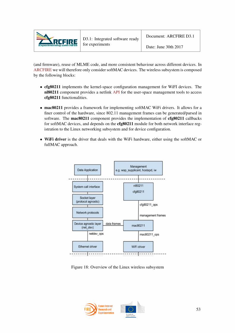
D3.1: Integrated software readyfor experiments
Document: ARCFIRE D3.1
Date: June 30th 2017
(and firmware), reuse of MLME code, and more consistent behaviour across different devices. InARCFIRE we will therefore only consider softMAC devices. The wireless subsystem is composedby the following blocks:
• cfg80211 implements the kernel-space configuration management for WiFI devices. Thenl80211 component provides a netlink API for the user-space management tools to accesscfg80211 functionalities.
• mac80211 provides a framework for implementing softMAC WiFi drivers. It allows for afiner control of the hardware, since 802.11 management frames can be generated/parsed insoftware. The mac80211 component provides the implementation of cfg80211 callbacksfor softMAC devices, and depends on the cfg80211 module for both network interface reg-istration to the Linux networking subsystem and for device configuration.
• WiFi driver is the driver that deals with the WiFi hardware, either using the softMAC orfullMAC approach.
Figure 18: Overview of the Linux wireless subsystem
53

D3.1: Integrated software readyfor experiments
Document: ARCFIRE D3.1
Date: June 30th 2017
2.3.2 Data path and Management paths
The architecture depicted in Figure 18 includes a datapath and a management path. The datapathdeals with IEEE 802.11 data frames, while the management path deals with IEEE 802.11 man-agement frames. Regarding IEEE802.11 control frames, as most of them are used for time-criticaloperations (such as ACK), they are usually handled by the hardware. The mac80211 modulehandles both data and management paths.
The mac80211 module is the one in charge of publishing a softMAC WiFi device through astruct net device to the rest of the Linux network subsystem, as it provides the implemen-tation of the netdev ops callbacks (which Ethernet drivers provide directly), thus making WiFiinterfaces indistinguishable from Ethernet interfaces to most of the actors in the OS and user-spaceapplications. Figure 19 shows where the shim Ethernet VLAN IPCP is placed in the architecture,between the network stack (e.g. RINA) and the device-agnostic layer (net dev); this clearlyexplains why this shim DIF can be re-used for the I/O functionalities of the Shim DIF over WiFi.
Figure 19: Architecture of the Shim WiFi datapath. The existing Shim DIF over Ethernet is reusedin full.
To implement the layer management part of the Shim DIF over WiFi, which must interact withthe mac80211 block (MLME in IEEE802.11), there are two possible options, shown in Figure 20:
1. Implement also the layer management functionalities in kernel-space, similar to what hap-pens for the other Shims (e.g. Shim TCP/UDP, Shim Ethernet VLAN, Shim Hypervisor). Inthis case it would be necessary to directly use the API provided by the mac80211 module.
54

D3.1: Integrated software readyfor experiments
Document: ARCFIRE D3.1
Date: June 30th 2017
2. Implement the layer management functionalities in user-space, by relying on the netlinkAPI (nl80211).
Figure 20: Two options for the layer management path of the Shim WiFi. The one on the top (i.e.implementation with an user-space daemon) has been selected by ARCFIRE.
The first option would require the various management operations (i.e. scan, authentication,association, and AP functionality) to be developed from scratch by ARCFIRE, which is not con-venient. On the other hand, open source user-space tools implementing these management func-tionalities (as outlined by the second option) are already available and are fit to be reused byARCFIRE. In this case the Shim WiFI IPCP would be an user-space daemon (similar to thenormal IPCP daemon) integrated with the existing tools, as depicted in Figure 20. In particular,ARCFIRE has investigated hostapd[16] and wpa supplicant [17], for which an overviewis given in subsubsection 2.3.3.
2.3.3 Introduction to hostapd and wpa supplicant
hostapd is a daemon implementing a WiFi access point and authentication server. It implementsIEEE 802.11 access point management, IEEE 802.1X/WPA/WPA2/EAP Authenticators, RADIUSclient, EAP server, and RADIUS authentication server. The current release supports Linux (HostAP, madwifi, mac80211-based drivers) and FreeBSD (net80211). wpa supplicant is another
55

D3.1: Integrated software readyfor experiments
Document: ARCFIRE D3.1
Date: June 30th 2017
daemon implementing the IEEE 802.1X/WPA components, which can be used by client stations.It supports key negotiation with a WPA authenticator and it controls the roaming and IEEE 802.11authentication/association of the wireless driver.
Both these programs are user-space tools that make use of a netlink socket to communicatewith the cfg80211 kernel module through the nl80211 API. Both of them also provide a con-trol interface that can be used by external programs for the various supported operations, statusinformation and event notifications. A small C library is available as a stand-alone C file (wpa -ctrl.c), that provides helper functions to facilitate the use of the control interface. Externalprograms can just compile and link this compilation unit and use the library functions documentedin (wpa ctrl.h) to interact with wpa supplicant or hostapd. The control interface canbe used to send commands and receive network-generated events.
2.3.4 Design and implementation of the Shim DIF over WiFi
The final design for the Shim WiFi is shown in Figure 21. The following modifications to IRATIhave been implemented:
Figure 21: Design of the Shim WiFi
• The user-space daemons (IPCM and IPCP daemons) have been refactored to handle multipletypes of IPCP processes (i.e. the normal IPCP and the shim WiFi IPCP layer management).
56

D3.1: Integrated software readyfor experiments
Document: ARCFIRE D3.1
Date: June 30th 2017
This has been done with the same abstract factory design pattern used in the kernel-spacecode. In detail, a new AbstractIPCProcessImpl abstract class has been defined. Twoconcrete subclasses have been defined: NormalIPCProcessImpl to implement the nor-mal IPCP and ShimWifiIPCP to implement the Shim WiFi IPCP. The concrete classescan override the abstract methods depending on the specific IPCP type. The IPCPFactoryclass has been modified to be able to create instances of the different types of IPCP, accord-ing to a type parameter. Possible types are NORMAL IPC PROCESS for the normal IPCP,SHIM WIFI IPC PROCESS STA for client WiFi IPCP running in UE, and SHIM WIFI -IPC PROCESS AP for WiFi IPCP running in the AP. The ShimWifiIPCP implementsboth variants.
• During the creation of a shim WiFi IPCP, the IPCM creates a shim WiFi IPCP daemon inuser-space (management path) and an shim Ethernet VLAN IPCP in kernel-space (datap-ath). The shim WiFi IPCP daemon spawns an instance of hostapd or wpa supplicant,depending on the IPCP subtype (AP or client, respectively), and connects to the associatedcontrol interface.
• The shim WiFi IPCP user-space daemon only needs to support the enrolment method, sincethe flow allocation is handled in kernel-space (by the shim Ethernet IPCP). In detail, WiFienrolment operation is implemented by invoking the scan, authenticate and associate mech-anisms provided by hostapd/wpa supplicant.
ShimWifiSta IPC Process Impl
Shim Wifi IPC Process Daemon
WPASupplicant Daemon WPA
Controller
Unix Domain Socket
Netlink Socket
Netlink Socket
Netlink Socket
To shim-eth-vlan IPCP To cfg80211
To IPCM Daemon
allocate_flow deallocate_flow
register_app unregister_app assign_to_dif enroll_to_dif
disconnect_neigh media_report
Kernel space
User space
allocate_flow deallocate_flow
register_app unregister_app assign_to_dif
launch_wpa create_crtl_conn
scan enable_net disable_net select_net
bssid_reassociate disconnect
Figure 22: Interaction between Shim Wifi IPCP Daemon and other IRATI components
Figure 22 shows the interaction of the ShimWifiIPCP daemon and the other components ofthe IRATI software architecture. The Figure illustrates the case of a mobile host - the access pointconfiguration is similar but using hostapd instead of WPA Supplicant.
57

D3.1: Integrated software readyfor experiments
Document: ARCFIRE D3.1
Date: June 30th 2017
The IPCP Daemon communicates with the ShimWifiIPCP daemon via a Netlink socket, aswith any other type of user-space IPCP Daemon. It requests the IPC Process to allocate/deallocateflows, register/unregister applications, change its assignment to a specific DIF and control applica-tion connections to specific neighbours. The ShimWifiIPCP Daemon is composed of two mainclasses:
• ShimWifiSTAIPCPImpl. This class is the handler of all the messages coming from theIPCM and the shim-eth-vlan IPCP in the kernel associated to the ShimWifiIPCP.
• WPAController. This class abstracts out lifecycle management of an instance of aWPASupplicant daemon, as well as communications with it.
The ShimWifiIPCP daemon delegates all the calls related to flow and application registra-tion management to its companion shim-eth-vlan IPCP in the kernel, and notifies the resultsback to the IPCM daemon. DIF assignment, enrolment to DIF and disconnection to neighboursare the tasks where the ShimWifiIPCP Daemon carries out specific processing. Specifically:
• DIF assignment. The Daemon forwards the request to the shim-eth-vlan IPCP and,upon receiving a successful response from the kernel, creates an instance of the WPASup-plicant daemon to manage the WiFi interface associated to the shim IPCP. Upon suc-cessful instantiation of WPASupplicant, the ShimWifiIPCP daemon opens a UNIXdomain socket to be able to manage it.
• DIF enrolment. The ShimWifiIPCP daemon maps an enrolment request to an attach-ment request at the 802.11 layer, asking the WPASupplicant to perform an associationto the base station whose SSID is the DIF name of the enrolment request, and whose BSSIDis the process name of the neighbour IPCP parameter in the enrolment request. The currentversion of the code assumes that WPASupplicant has been configured with the creden-tials for successfully attaching to the access point.
• Disconnection from a neighbor. This request from the IPCM daemon is mapped to arequest to de-attach from a base station at the 802.11 layer. The ShimWifiIPCP requestsWPASupplicant to disassociate from the access point whose BSSID is the process nameof the neighbour IPCP parameter in the disconnection request.
The processing of the enrolment and disconnection operations is controlled by the state ma-chine depicted in Figure 23. Initially the ShimWifiIPCP starts at the DISCONNECTED state.When it receives an Enroll to DIF request from the IPCM daemon, it invokes the select-network method of the WPAController class to trigger the attachment to the neighbour,and modifies the internal state to ENROLMENT STARTED. Eventually the WPAController re-ceives a Trying to associate with message from the WPASupplicant, and calls anoperation on the ShimWifiIPCP to update the state to TRYING TO ASSOCIATE.
58

D3.1: Integrated software readyfor experiments
Document: ARCFIRE D3.1
Date: June 30th 2017
ENROLLMENT STARTED
IPCM: Enroll to DIF
request
WPACtrl: Trying to associate with …
Timer fires
Timer fires
TRYING TO ASSOCIATE
Timer fires
WPACtrl: Associated with… ASSOCIATED
Timer fires
WPACtrl: Key negotiation completed
with …
KEY NEGOTIATION COMPLETED
WPACtrl: CTRL-EVENT-CONNECTED
ENROLLED DISCONNECTED WPACtrl: CTRL-EVENT-
DISCONNECTED
IPCM: Enroll to DIF request
IPCM: Disconnect from neighbor
Figure 23: State machine controlling attachment to a neighbour in the shim IPCP over WiFi
int scan(void);std::string scan_results(void);int enable_network(const std::string& ssid, const std::string&
bssid);int disable_network(const std::string& ssid, const std::string&
bssid);int select_network(const std::string& ssid, const std::string&
bssid);int bssid_reassociate(const std::string& ssid, const std::string
& bssid);int disconnect(void);
Listing 2: WPA Controller API
In case of a successful attachment, the WPAController will receive three more messages:Associated with, Trying to authenticate with and CTRL-EVENT-CONNECTED.These messages will cause the ShimWifiIPCP state to transition to the ENROLLED state.
If the WAPController receives the CTRL-EVENT-DISCONNECTED message from theWPASupplicant, the ShimWifiIPCP state will transition to DISCONNECTED, as will alsohappen upon reception of a Disconnect from Neighbour Netlink message from the IPCMdaemon - in this case the ShimWifiIPCP will invoke the disconnect operation of theWPAController class.
Finally, when the ShimWifiIPCP receives an Enroll to DIF request from the IPCMdeamon, it goes back to the ENROLMENT STARTED state, but this time it may invoke the select-network command or the bssid-reassociate command depending on the new neighbour
59

D3.1: Integrated software readyfor experiments
Document: ARCFIRE D3.1
Date: June 30th 2017
belonging to the same or a different SSID as the old neighbour.Last but not least, the ShimWifiIPCP has a timer that periodically requests WPASuppli-
cant to scan the media and gather information on the access points that are in the range ofthe ShimWifiIPCP. This information is the SSID, BSSID, authentication policies and signalstrength. The ShimWifiIPCP sends the results of the scan to the IPCM via a Netlink message,so that the IPCM has enough information to decide whether it should execute a handover to anotheraccess point.
Proper configuration of the scanning task is critical to the performance (i.e.: throughput andlatency) of the flows supported by the ShimWifiIPCP, since the WiFi interface cannot scanand transmit/receive data at the same time. Hence, the period of scanning as well as the con-figuration of the WPASupplicant parameters that control the duration of the scan are an im-portant part of the ShimWifiIPCP configuration. The current implementation uses a defaultWPASupplicant configuration, scanning the media every 60 seconds. Clearly there is a trade-off in the length of the scans in minimising the performance penalty experienced by running flowsand maximising the number of access points that can be discovered during the scan period ([18]).The optimisation of this configuration for different environments will be carried out using dataprovided by the experimentation tasks in WP4.
2.3.5 Changes to the IPCM Daemon: Mobility Manager
Once IRATI supports overlaying RINA on top of WiFi layers via a shim DIF that can controlattachment and detachment to access points, there is still one more component needed to sup-port mobility: a decision-maker managing handovers across several WiFi access points. This“Mobility Manager” must have access to the local information of all the DIF in the system,as well as AP that are reachable via local shim Wifi IPCP and their signal strength levels. Hence,IRATI entity most fit to carry out this task is the IPC Manager daemon (or IPCM from now on).
Since a Mobility Manager is clearly an optional component of the IPCM (it is only re-quired by some systems in certain scenarios), it has been implemented as one of the IPCM ex-tensions using the IPCM extension framework called Addons (the other available addons are theIPCM Console, the Management Agent and the Scripting Engine).
A general purpose Mobility Manager reacts to events that report information about thestatus of the different WiFi networks visible to the system where RINA is running. It reacts tothose events according to the policies set by the Network Administrator, which control the choiceof which WiFi network to join, the signal strength threshold for initiating a handover, etc. Since thegoal of ARCFIRE is to experiment with mobility on RINA networks under controlled conditions,it is not necessary, nor would be cost-effective for the project goals, to implement a full-fledgedMobility Manager; therefore the Mobility Manager has been designed and implemented tocontrol mobility in well-known experimental scenarios.
The current implementation of the Mobility Manager is able to control the scenarioshown in Figure 17. Although the scenario is specific, is illustrative of the capabilities required by
60

D3.1: Integrated software readyfor experiments
Document: ARCFIRE D3.1
Date: June 30th 2017
a general-purpose Mobility Manager:
• It receives reports of ShimWifiIPCPs about the status of the WiFi networks reachable bythe system.
• It triggers handovers according to a policy set by the network administrator. The current pol-icy is to start a handover on every report received (the policy is just valid for demonstrationand experimentation purposes).
• Control of handover is carried out by interacting with normal and shim WiFi IPC Processesvia the Enroll to DIF and Disconnect from neighbour operations.
2.4 Support for seamless renumbering
Many networks eventually need to be renumbered [19], which means updating the addresses for asubset or all the network nodes. This may be necessary for various reasons. It may be happen thatthe network has grown to the point that its current addressing strategy is no longer effective or doesnot scale. Or perhaps the upstream provider changes and the nodes need to get new addresses fromthe new provider3. In any case, renumbering in IP networks is a complex procedure involving anumber of steps:
1. the interfaces of network switches and routers need to be assigned new IP addresses;
2. the resulting new routing information need to be propagated;
3. ingress and egress filters need to be updated - as well as firewalls and access control lists;
4. hosts need to get new addresses;
5. DNS entries need to be updated.
As introduced in ARCFIRE’s D2.2 [8] RINA supports the live renumbering of a networkwithout impacting the service (e.g. the flows) the network is currently providing. This capabilityis also a key feature to efficiently support mobility with location-dependent addressing, since itallows a DIF to assign a different address to an IPCP when it moves far enough that its currentaddress is no longer aggregatable.
The IRATI codebase has been upgraded to support multiple addresses and dynamically add orremove them; most of the changes are related to the update of all those data structures that wereassuming a single address per IPC Process, the link-state routing policy and to the synchronisationmechanisms between user-space and kernel IPC Process components.
3provider-based addresses are the norm in the current Internet
61

D3.1: Integrated software readyfor experiments
Document: ARCFIRE D3.1
Date: June 30th 2017
In addition to that, a new illustrative namespace management policy has been implemented toperiodically trigger IPCP address changes; this policy enables renumbering demos and experimen-tations. The Namespace Manager is the layer management task of the IPC Process that managesits naming and addressing. This renumbering policy is configured with a certain address rangeand an address change period; it repeatedly sleeps a random amount of time within the configuredperiod and at each wake-up it changes the IPC Process address (picking an unused address withinthe range it has been configured with). When the address change occurs, the Namespace Managersends an event to the other tasks of the IPC Process, which react according to the steps depicted inFigures 24, 25 and 26. In more detail:
• The routing policy (link-state is the only one implemented to date) starts advertising the newaddress to its neighbors via routing updates. It also sets a timer to deprecate the old addressafter a while. The timer interval is specified by the IPCP configuration.
• The core IPCP logic updates its internal data structures and sends a message to the kernel tonotify about the address change.
• The kernel updates the internal RMT data structures (it will now accept PDU whose des-tination address is the old one or the new one) and sets two timers, one to start using thenew address and another one to deprecate the old address. The interval for both timers arespecified by the IPCP configuration.
• When the timer to start using the new address fires, the kernel modifies the EFCP datastructures of active connections in order to use the new address as the source address for alloutgoing EFCP PDU.
• A corresponding timer also fires in user-space, so that the Namespace Manager policy canupdate the application-to-address mappings for the applications registered locally (e.g. tothe IPC Process itself), and disseminate the changes to its neighbours via CDAP.
• When the timer to deprecate the old address fires, the kernel removes the old address fromthe RMT data structures, so that the IPCP no longer accepts PDU with the old address asdestination.
• The corresponding timer also fires in user-space, causing the link-state routing policy toadvertise the old address as deprecated to its neighbours. The next time the PDU Forwardingtable is computed all entries associated to the old address will be removed.
2.4.1 Updates to librina
Internal events. Two new internal events have been added: AddressChangeEvent andNeighborAddressChangeEvent. The first one is used by the Namespace Manager to in-form the other IPC Process Daemon components about the IPCP address change. The event class
62

D3.1: Integrated software readyfor experiments
Document: ARCFIRE D3.1
Date: June 30th 2017
IPC Process Daemon Namespace
Manager Internal Event Manager
Core IPCP Logic
Routing policy
1
2 2
3 Send CDAP message with routing update
3 Set timers
Address Change!
3 Set timers
Recompute Fwd table
3 Send NL message to Kernel about Address
Change
Kernel
Normal IPC Process
4 Set timers
RMT 4
Accept new address
EFCP
Figure 24: Sequence of events triggered by an address change in the Namespace Manager
IPC Process Daemon Routing
policy Internal Event Manager
Core IPCP Logic
3 Send CDAP message with mappings update
Update Name to @ mappings
3
Kernel
Normal IPC Process Timer fires!
RMT
1 Update data
structures to start using new @ as
source @
EFCP
Timer fires! 1 2
Namespace Manager
2
Figure 25: Sequence of events triggered when the “start using new address” timer fires
63

D3.1: Integrated software readyfor experiments
Document: ARCFIRE D3.1
Date: June 30th 2017
IPC Process Daemon Namespace
Manager Internal Event Manager
Core IPCP Logic
3 Send CDAP message with routing update
Deprecate old address Compute
tables
3
Kernel
Normal IPC Process Timer fires!
RMT
1
Update data structures to stop
accepting old address
EFCP
Timer fires! 1 2
2
Routing policy
Figure 26: Sequence of events triggered when the “deprecate old address” timer fires
contains the new IPC Process address, the old IPCP address, the timeout interval to start using thenew address and the timeout interval to deprecate the old address.
class AddressChangeEvent: public InternalEvent {public:
AddressChangeEvent(unsigned int new_address,unsigned int old_address,unsigned int use_new_timeout,unsigned int deprecate_old_timeout);
const std::string toString();
unsigned int new_address;unsigned int old_address;unsigned int use_new_timeout;unsigned int deprecate_old_timeout;
};
64

D3.1: Integrated software readyfor experiments
Document: ARCFIRE D3.1
Date: June 30th 2017
The second event is used by the Enrolment Task, in order to update its internal data structureswhen the address of a neighbour IPCP changes. The data contained by this object is shown in thefollowing code listing (neighbor name, new neighbour address, old neighbour address).
class NeighborAddressChangeEvent: public InternalEvent {public:
NeighborAddressChangeEvent(const std::string& neigh_name,
unsigned int new_address,unsigned int old_address);
const std::string toString();
std::string neigh_name;unsigned int new_address;unsigned int old_address;
};
KernelIPCProcess and Netlink support. The KernelIPCProcess class, which abstractsthe communication between the IPC Process components in the user-space and the kernel, has beenupgraded with another primitive called changeAddress. This function informs the kernel aboutthe IPC Process address change, passing the new IPCP address, the old one, the timeout intervalto start using the new address and the timeout interval to deprecate the old address. This is doneby creating a Netlink message, represented by the IPCPAddressChangeRequestMessageclass, that delivers the information to the kernel. The Netlink parsing infrastructure has beenextended to support the generation and parsing of this message.
unsigned int changeAddress(unsigned int new_address,unsigned int old_address,unsigned int use_new_t,unsigned int deprecate_old_t);
65
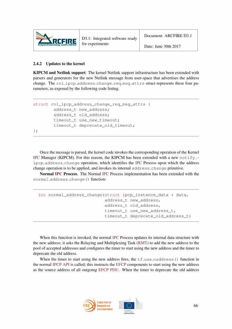
D3.1: Integrated software readyfor experiments
Document: ARCFIRE D3.1
Date: June 30th 2017
2.4.2 Updates to the kernel
KIPCM and Netlink support. The kernel Netlink support infrastructure has been extended withparsers and generators for the new Netlink message from user-space that advertises the addresschange. The rnl ipcp address change req msg attrs struct represents these four pa-rameters, as exposed by the following code listing.
struct rnl_ipcp_address_change_req_msg_attrs {address_t new_address;address_t old_address;timeout_t use_new_timeout;timeout_t deprecate_old_timeout;
};
Once the message is parsed, the kernel code invokes the corresponding operation of the KernelIPC Manager (KIPCM). For this reason, the KIPCM has been extended with a new notify -ipcp address change operation, which identifies the IPC Process upon which the addresschange operation is to be applied, and invokes its internal address change primitive.
Normal IPC Process. The Normal IPC Process implementation has been extended with thenormal address change() function:
int normal_address_change(struct ipcp_instance_data * data,address_t new_address,address_t old_address,timeout_t use_new_address_t,timeout_t deprecate_old_address_t)
When this function is invoked, the normal IPC Process updates its internal data structure withthe new address; it asks the Relaying and Multiplexing Task (RMT) to add the new address to thepool of accepted addresses and configures the timer to start using the new address and the timer todeprecate the old address.
When the timer to start using the new address fires, the tf use naddress() function inthe normal IPCP API is called; this instructs the EFCP components to start using the new addressas the source address of all outgoing EFCP PDU. When the timer to deprecate the old address
66

D3.1: Integrated software readyfor experiments
Document: ARCFIRE D3.1
Date: June 30th 2017
fires, the tf kill oaddress() function in the normal IPCP API is called; this instructs theRMT to remove the old IPCP address from the pool of accepted addresses.
Relaying and Multiplexing Task. The internal structures of the RMT have been updated tokeep a list of accepted addresses, rather than a single address. The list contains the addresses thatthe RMT considers belonging to itself. As a result, when a PDU arrives, its destination addressmust be compared against all the addresses in the list, and if there is a match the PDU is deliveredlocally, otherwise it is forwarded. The RMT has also been updated with two operations that allowthe normal IPCP to add/remove addresses to the list, i.e. rmt address add() and rmt -address remove().
Error and Flow Control Protocol. The efcp address change() function, now exposedby the EFCP module, updates the local EFCP connections (i.e. those that have the IPC Processas an endpoint), so that they can start using the new address. Also the EFCP code for incomingPDU processing has been modified, to check if the source address of the other EFCP endpoint haschanged. If so, the EFCP state vector belonging to this connection is updated with the new address,that will be used as a destination address for subsequent transmissions on the same connection.
2.4.3 Updates to rinad: IPC Process Daemon
Namespace Management policy. The address change namespace management policy sethas been implemented as a standalone plugin within the IPCP Daemon source tree. This policy setis configured with the values of timeout intervals to start using the new address and deprecate theold address, the average time period for address change and an address range. This informationis used by the policy set to periodically start a timer that triggers a change in the IPC Processaddress, within the range specified by the IRATI implementation administrator. The only purposeof this policy is to experiment with challenging renumbering scenarios using the IRATI RINAimplementation.
IPC Process Implementation. The main IPCP class subscribes to AddressChangeEventevents. When such an event happens, the IPC Process invokes the addressChange function,which updates its internal data structures; starts two timers (start using new address and deprecateold address) and invokes the Kernel IPC Process changeAddress operation.
When the first timer fires, the IPC Process Implementation class sets the new address as theactive address. When the second timer fires, the IPCP erases any reference to the old address.
void addressChange(rina::AddressChangeEvent * event);
Enrolment Task. The Enrolment Task (ET) also subscribes to AddressChangeEventevents. On such events, the ET sends a CDAP WRITE message to all the directly attached neigh-
67

D3.1: Integrated software readyfor experiments
Document: ARCFIRE D3.1
Date: June 30th 2017
bours of the IPC Process, targeting the /difManagement/enrollment/neighbors ob-ject. This message causes neighbour IPC Processes to update the portion of their RIB representingthe Neighbour IPCP that has changed its address. In more detail, when this message is receivedby a neighbour, it is processed by the NeighborsRIBObj class, which invokes the EnrolmentTask’s update neighbor address() operation to update the Neighbor RIB object. Thisalso triggers an internal NeighborAddressChangeEvent to notify other interested IPCPmodules.
void update_neighbor_address(const rina::Neighbor& neighbor)
Namespace Manager. In addition to the main IPCP class and the ET, also the NamespaceManager (NSM) subscribes to AddressChangeEvent events. When they occur, the NSM setsa timer to start using the new address. When the timer fires, the NSM updates the contents ofthe Directory Forwarding Table (DFT), if needed4. This is a policy-dependent operation, sinceeach DIF has its own DFT update strategy. The default implementation uses a fully-replicatedDFT, therefore when the timer fires the NSM collects all the DFT entries related to applicationregistered locally (i.e. to the IPCP itself); if there are any, each entry is updated with the new IPCPaddress and this change is disseminated to the neighbours by means of CDAP messages.
Link-state routing policy. In addition to the modifications required to handle address changeevents the default link-state routing (LSR) policy also has undergone a redesign, due to the verynature of addresses. As a matter of fact, addresses are just temporary identifiers, therefore theLSR policy (or any other routing policy) needs to keep track of both names and addresses for thevarious IPC Processes in the DIF. In this way, each IPCP node in the DIF connectivity graph canbe identified by the IPCP name, and not by its temporary address. The address can be treated asa temporary property of each IPCP. This is necessary because an IPCP can temporary have moreaddresses, and so two different addresses do not necessarily correspond to two different nodes inthe graph. The previous implementation of the LSR policy used the address as IPCP identifiers inthe connectivity graph; a redesign of the internal data structures and some of the internal API hasbeen necessary. In particular, the definition of the FlowStateObjects encoded in the CDAPmessages exchanged in routing updates has been changed as follows:
message flowStateObject_t {optional string name = 1;repeated uint64 addresses = 2;
4the DFT maps names of registered applications to IPCP addresses
68

D3.1: Integrated software readyfor experiments
Document: ARCFIRE D3.1
Date: June 30th 2017
optional string neighbor_name = 3;repeated uint64 neighbor_addresses = 4;optional uint32 cost = 5;optional uint32 sequence_number = 6;optional bool state = 7;optional uint32 age = 8;
}
Additional changes to the LSR policy implementation have been necessary to address renum-bering related events. The LSR policy subscribes to AddressChangeEvent events. Whenone of these occurs, the LSR adds the new address to all the required FlowStateObjectsand marks the FlowStateDatabase as updated (which will trigger a routing update). TheLSR also sets a timer to deprecate the old address. When this timer fires, the old address is re-moved from the required FlowStateObjects, causing another routing update. The LSR alsosubscribes to NeighborAddressChangeEvent events. When these occur, the LSR policybehaves in a similar way, the only difference being in the set of FlowStateObjects affectedby the event.
2.5 IP over RINA
A set of use cases for RINA adoption gravitate around the idea of using RINA as an underlay tocurrent network technologies, mainly IP or Ethernet. RINA can be seen as a more flexible, simpleand powerful alternative to MPLS for supporting IP VPNs, implementing BGP-free ISP cores orproviding Carrier Ethernet services. One of the ARCFIRE experiments described in [7] focuses oninvestigating RINA as an alternative to MPLS for supporting IP traffic, hence the need to developsupport for interfacing RINA to the IP layer.
IRATI is well positioned to achieve this integration, since the data-transfer components ofRINA DIF are already implemented in the kernel, were the code for the IP stack also resides.The goal of the implementation is to instantiate the necessary infrastructure of the Linux kernelnetworking framework that allows RINA flows to be used as a transport for IP traffic. This goalcan be achieved by presenting each of these RINA flows as a software network device (NIC); theIP routing table is then populated with the proper entries, which reference the software networkdevices. The following sections explain the design and implementation of the enhancements to theIRATI RINA implementation aimed to support the transport of IP traffic via RINA flows.
2.5.1 Service model and application naming convention
The general service model of IP over RINA is illustrated by Figure 27. A DIF provides flowsbetween two IP network prefixes (the model supports flows between two or more IP network
69

D3.1: Integrated software readyfor experiments
Document: ARCFIRE D3.1
Date: June 30th 2017
prefixes, but the current implementation is limited to two). The network administrator determineswhich IP network prefixes are available through which DIF, and configures the system to registerthose IP network prefixes to each corresponding DIF. Hence, to the DIF, an IP network prefix isjust another application.
DIF
DIF DIF
10.10.100.0/24 10.10.90.0/24
System A System B
3 5 port-id port-id
App name: <IP prefix>-<VPN id>-RINA_IP-
Process name
Process instance
Entity name
Figure 27: Service model for IP over RINA flows, with application naming conventions
A key aspect of how to use IP over RINA is how to name the IP application endpoints thatact as the source and destination(s) of the flows provided by DIF. To make a proper choice, wehave to take into account what are the requirements for DIF supporting IP or other networkingtechnologies as applications.
• A DIF should be able to support flows between IP endpoints, Ethernet endpoints, other typeof network protocol endpoints and normal applications at the same time if it wishes to doso.
• A DIF should be able to support multiple IP VPNs, with each IP VPN being completelyisolated from each other (hence re-use of IP addresses across VPNs must be supported).
An application name in RINA has four parts: the process name, the process instance, the entityname and the entity instance. We choose to make the following use of each one of the fields:
• The IP network prefix is the process name.
• The VPN id is the process instance (may be empty if no VPNs are used).
• A special label to signal that this is an IP over RINA flow is used as the application entity.The label RINA IP is used by current implementations.
The application entity is used to make the IPCP at both ends of the flow aware of the factthat it is an IP over RINA flow and therefore specific actions have to take place upon flow allo-cation/deallocation (in addition to the regular ones). These actions are specific to interfacing IP
70
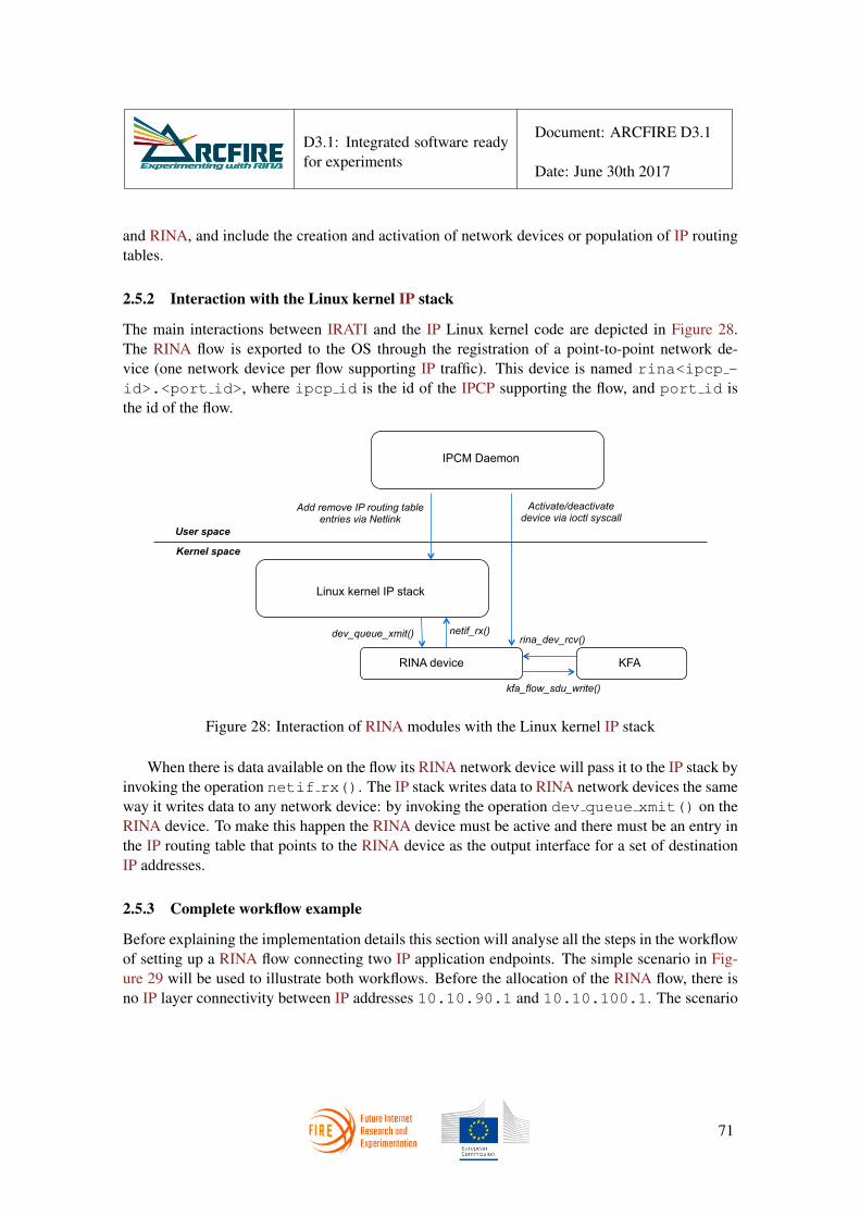
D3.1: Integrated software readyfor experiments
Document: ARCFIRE D3.1
Date: June 30th 2017
and RINA, and include the creation and activation of network devices or population of IP routingtables.
2.5.2 Interaction with the Linux kernel IP stack
The main interactions between IRATI and the IP Linux kernel code are depicted in Figure 28.The RINA flow is exported to the OS through the registration of a point-to-point network de-vice (one network device per flow supporting IP traffic). This device is named rina<ipcp -id>.<port id>, where ipcp id is the id of the IPCP supporting the flow, and port id isthe id of the flow.
Linux kernel IP stack
Kernel space
User space
RINA device KFA
Add remove IP routing table entries via Netlink
Activate/deactivate device via ioctl syscall
netif_rx() dev_queue_xmit()
kfa_flow_sdu_write()
rina_dev_rcv()
IPCM Daemon
Figure 28: Interaction of RINA modules with the Linux kernel IP stack
When there is data available on the flow its RINA network device will pass it to the IP stack byinvoking the operation netif rx(). The IP stack writes data to RINA network devices the sameway it writes data to any network device: by invoking the operation dev queue xmit() on theRINA device. To make this happen the RINA device must be active and there must be an entry inthe IP routing table that points to the RINA device as the output interface for a set of destinationIP addresses.
2.5.3 Complete workflow example
Before explaining the implementation details this section will analyse all the steps in the workflowof setting up a RINA flow connecting two IP application endpoints. The simple scenario in Fig-ure 29 will be used to illustrate both workflows. Before the allocation of the RINA flow, there isno IP layer connectivity between IP addresses 10.10.90.1 and 10.10.100.1. The scenario
71

D3.1: Integrated software readyfor experiments
Document: ARCFIRE D3.1
Date: June 30th 2017
assumes that the DIF are already setup and enrolment has already taken place. In this example noVPNs will be created (which is in line with the capabilities of the current implementation: multipleIP VPNs are not supported yet).
DIF
Shim DIF over Ethernet
10.10.90.0/24
System A
port-id
eth0 10.10.90.1
eth1.39 eth1.39
eth0 10.10.100.1
System B
3
10.10.100.0/24
5 port-id
Figure 29: Simple scenario for an IP over RINA flow
The first step is for network administrators to register IP network prefixes to different DIF.To do so, the network administrator of System B can access the IPCM console and type thefollowing command:
• register-ip-prefix 10.10.100.0 24 normal.DIF
This will cause the registration of a application name 10.10.100.0|24-RINA IP- at theDIF normal.DIF (the orange DIF in the picture). Registration of IP network prefixes to DIFcould also take place remotely via the Management Agent. An equivalent registration operationcould take place at System A, but it is not required for this example.
Once registrations of IP network prefixes are done the network admin can request the allocationof flows. To do so, the network administration of System A accesses the IPCM console andrequests a flow between the IP prefixes 10.10.90.0/24 and 10.10.100.0/24 over the DIFnormal.DIF by typing the following command:
• allocate-iporina-flow 10.10.90.0 24 10.10.100.0 24 normal.DIF
This command will cause the IPCM at System A to request a flow to the IPCP Daemonbelonging to the DIF normal.DIF between applications 10.10.90.0|24-RINA IP- and10.10.100.0|24-RINA IP-. When the kernel is requested to allocate a port-id for the flow,it will detect that the flow will be used by the IP layer (due to the presence of the RINA IP label inthe application name). Then, in addition to assigning a port-id, the kernel will create and registera point-to-point network device for the flow, but it will not be activated yet.
72

D3.1: Integrated software readyfor experiments
Document: ARCFIRE D3.1
Date: June 30th 2017
Figure 30: RINA device information as displayed by ifconfig command
When the IPCM receives a notification that the flow has been successfully allocated, it activatesthe RINA device using the ifconfig command and adds a route to the destination IP prefix viathe RINA device using the ip route command. After this it is possible to ping 10.10.100.1from System A and 10.10.90.1 from System B.
Figure 31: IP routing table containing route through the RINA device
When the flow is deallocated (usually by the network administrator via the IPCM console), theIPCM sets the device state to down and removes the routing table entry associated to it. When thekernel is requested to deallocate the port-id, it also unregisters the network device and deletes anydata structure associated to it.
2.5.4 Implementation: user-space
The IPCM daemon is the only user-space IRATI component that has been extended to support theIP over RINA use case. The IPCM console has been extended with four commands that enable anetwork administrator to register and unregister IP prefixes, and to allocate and deallocate flowsbetween IP prefixes. Figure 32 shows how these commands are used.
The IPCM main class has been extended with a new component, called IP VPN Manager,which is in charge of managing the lifecycle of IP over RINA flows. This class takes care of thespecifics of registering IP network prefixes and allocating IP over RINA flows.
int add_registered_ip_prefix(const std::string& ip_prefix);int remove_registered_ip_prefix(const std::string& ip_prefix);bool ip_prefix_registered(const std::string& ip_prefix);
73

D3.1: Integrated software readyfor experiments
Document: ARCFIRE D3.1
Date: June 30th 2017
Figure 32: Usage of the commands related to flows between IP network prefixes
int iporina_flow_allocated(const rina::FlowRequestEvent& event);void iporina_flow_allocation_requested(const rina::
FlowRequestEvent& event);int get_iporina_flow_info(int port_id, rina::FlowRequestEvent&
event);int iporina_flow_deallocated(int port_id, const int ipcp_id);
Listing 3: Main functions of the IPVPNManager class
It is important to note that the generic operations required to register an application and allocatea flow are still processed by the main IPCM logic, but when the application entity contains theRINA IP label, the main processing logic also invokes the required operations of the IP VPNManager. The IP VPN Manager keeps a map of the registered IP network prefixes, so thatwhen the IPCM receives an allocate flow request the IP VPN Manager can respond positivelyor negatively depending on the presence/absence of the target IP network prefix.
Upon successful flow allocation the IP VPN Manager is responsible for invoking theifconfig and ip route commands to activate the RINA device and to add the route to theIP routing table. On flow deallocation the IP VPN Manager performs the inverse operations inorder to free the resources allocated for the flow: it deactivates the network device and removesthe entry from the routing table.
2.5.5 Implementation: kernel-space
An IP flow over RINA is treated by the kernel as a flow between two applications. Applicationflows terminate at the Kernel Flow Allocator (KFA), and flow data is consumed/writtenthrough read/write system calls on file descriptors managed by an IRATI specific I/O device. IPflows are similar, but the KFA flow structure is linked to a network device instead of a file descrip-tor. When the KFA processes the kfa flow create call (invoked when the kernel is requestedto allocated a port-id for a flow), it checks the application entity name of the application that willbe using the flow: if the application entity is named RINA IP, the KFA creates, initialises and
74

D3.1: Integrated software readyfor experiments
Document: ARCFIRE D3.1
Date: June 30th 2017
registers a network device associated to the flow.
int kfa_flow_create(struct kfa *instance,port_id_t pid,struct ipcp_instance *ipcp,ipc_process_id_t ipc_id,struct name *user_ipcp_name)
The RINA network device is a simple one, modelled after the loopback and tun networkdevices. As all devices it contains a private data structure to store device-specific information. TheRINA network device keeps a pointer to the KFA, a structure to hold device TX/RX statistics andthe port id of the flow associated to it.
struct rina_device {struct net_device_stats stats;struct ipcp_instance* kfa_ipcp;port_id_t port;struct net_device* dev;
};
Network devices have a number of attributes that control the interaction with higher layers (inour case the IP stack code). The RINA device attributes are shown in the listing below. The deviceneeds a minimum headroom and tailroom space in the SKB structures that will be passed to it,in order to be able to add RINA headers afterwards. This size should be computed dynamicallybased on the N-1 DIF(s) information, but for simplicity only an upper bound is provided in thecurrent implementation. The devices MTU should also be computed dynamically for the exactsame reasons. Since the RINA device is a virtual network device it has no hardware header, andits address length is 0. It is a point to point device where ARP (the Address Resolution Protocol)is not required.
/* This should be set according to the N-1 \acs{DIF} properties,
* at the moment an upper bound is provided */dev->needed_headroom += RINA_EXTRA_HEADER_LENGTH;dev->needed_tailroom += RINA_EXTRA_HEADER_LENGTH;/* This should be set depending on supporting \acs{DIF} */dev->mtu = 1400;dev->hard_header_len = 0;dev->addr_len = 0;dev->type = ARPHRD_NONE;
75

D3.1: Integrated software readyfor experiments
Document: ARCFIRE D3.1
Date: June 30th 2017
dev->flags = IFF_POINTOPOINT | IFF_NOARP | IFF_MULTICAST;
When the IP layer wants to transmit a packet through the device it invokes the dev queue -xmit() operation, which causes the invocation of the rina dev start xmit() operation ofthe network device. This operation retrieves the rina device private data structure, creates a SDUstructure from the SKB pointer passed to the call and invokes the KFA kfa flow sdu -write() operation. On the RX side, when the KFAs kfa sdu post() operation is invokedon an IP flow, the KFA calls the rina dev rcv() operation of the device. This operation setsIP as the SKBs protocol, and the RINA device as the SKBs device before invoking netif rx().
Finally, when the kfa flow destroy() operation is invoked to release the flow, the KFAdoes the usual processing, and checks if the pointer to the RINA device of the flow structure isnot NULL. If so, the flow was an IP over RINA flow, and the KFA adds a work item to the KFAflow deallocation work queue containing instructions to unregister and free the network device. Awork queue is used as opposed to immediately freeing the resources since the device cannot beunregistered in an atomic context.
3 Enhancements to the management system
The aim of the original DIF Management System (DMS), as designed and developed in FP7PRISTINE, was to establish new management principles based on the RINA architecture. Thosenew principles have been demonstrated for monitoring and repair of a RINA network. The designand implementation of the PRISTINE DMS follows the concept of being “closed for change yetopen for extension”. This makes it very easy to evolve the original DMS according to the goalsand requirements of ARCFIRE.
In order to focus on management principles, the PRISTINE DMS was built from scratch.The reason for that is that RINA-based management principles required an approach to networkmanagement very different from the classic approach, thus not supported by readily available thirdparty products or systems. This led to the DMS being largely a proprietary management system,with few connections to other management or operational components. While this allowed toexperiment with and understand the nature of the new management principles, it also made it hardto use the DMS, especially for RINA users.
For ARCFIRE, we decided to substitute parts of the DMS, i.e. identified components, withstandard software systems. Furthermore, there are now components available as open source andcommercial solutions which are flexible enough to realise management strategies, and should bepreferred. However, the enhancements of the DMS in ARCFIRE do not take away key designand development achievements. For instance, the operational semantic of events in the DMSwas defined using Domain-Driven Design (DDD) concepts [20] and described throguh a Domain-Specific Language (DSL), which in turn uses many of the patterns described in [21]. This DDDapproach will still be present in the DMS.
76

D3.1: Integrated software readyfor experiments
Document: ARCFIRE D3.1
Date: June 30th 2017
Figure 33: DMS Principles
The key principles and the main PRISTINE DMS building blocks are shown in figure 33. Thecore of the DMS is the manager, which maintains instances of management strategies realisingnetwork management tasks. The manager communicates with the Management Agent (MA) toreceive CDAP messages about the RINA network and to send CDAP operations for repair actions.The shared state is maintained in the RIB, whereas existing RIB instances are synchronised acrosscomponents. The main scope for a RINA operator then is to define and deploy the managementstrategies.
Evolving the DMS towards the ARCFIRE goals and requirements is a threefold process. First,the DMS must now handle an initial configuration of a RINA network, including the instantiationof all involved nodes and their initial configuration. So the DMS now needs to play a pro-activerole in the operation of a RINA network. Second, the DMS needs to realise a closed controlloop coordinating the configuration of DIF and RINA nodes using the autonomic capabilities thatRINA offers. This requires some new components (such as a RINA orchestrator) as well as anenhanced event flow. Third, the DMS must provide interfaces towards and integration with exter-nal, standard, 3rd party components and systems. This is important to the uptake of RINA in anoperational environment as well as to minimise the development work on a RINA managementsystem. The DMS now will need to provide means to consume and produce events defined andspecified outside its own DDD/DSL universe.
Figure 34 shows the evolved, enhanced, DMS in and for ARCFIRE. The core is an enhancedmanager, now named DMS Strategy Engine (DSE). This component allows to deploy and executemanagement strategies, similar to what the original DMS manager did. However, the actual re-alisation of the DSE does not require a DMS specific implementation, but can be taken over byany available rule engine or advanced management policy engine. A candidate we are about tointegrate here is the APEX engine (see for instance [10]).
The DSE sends action events to the MA. This flow is not changed and the CDAP connector isused for syntactic and protocol translation. The DSE also sends action events to a new component
77

D3.1: Integrated software readyfor experiments
Document: ARCFIRE D3.1
Date: June 30th 2017
Figure 34: ARCFIRE Evolved DMS
called DMS RINA Orchestrator (DRO) for network and node creation and configuration actions.The DRO is a facade (or thin wrapper) of the IRATI demonstrator and the ARCFIRE Rumbasystems. It will allow to create the configuration for a RINA network, start/terminate individualnodes, configure individual nodes and add/remove DIF as management operations. The DRO isnecessary to realise the experiments described in section 3 in [7].
To realise a closed control loop, the MA and the DRO send events (such as status reports ofmanagement actions or change notifications) back to the DSE. An optional component, not de-veloped for ARCFIRE, is an analytics engine that could be used to aggregate events or to createdeeper insight into network situations. Once events are received by the DSE, management strate-gies can be triggered again.
The discussed enhancements also address the new requirement of managing RINA networks atscale, ranging from small, medium, large to huge networks. The rationale for those enhancementsare discussed in [8] in section 4. The following list details the evolved DMS:
• Enhance the Manager’s strategy sub-system, which is supporting only currently used OODA-based strategies (Observe, Orient, Decide, Act). The new policy model ([8] sub-section4.6.2) allows for a radical new design of strategies, including the support of new strat-egy models such as action policy-based strategies (similar to ECA and CA policies), goal-oriented strategies, utility function strategies, and others. Realising this means to substitutethe strategy-subsystem in the manager with a new sub-system. Due to its modular softwaredesign, this can be done without impacting any other parts of the DMS.
• Fully introduce programmatic access to the RIB for all components/systems in the DMS.The current DMS implementation uses the GDRO instrumentation to generate program-matic access to the RIB. The developed API as well as the underlying RIB store are rathersimple and might not provide sufficient RIB access for all management use cases. Thus, theaccess to the RIB needs to be generalised, a new API designed, and the GDRO instrumenta-
78

D3.1: Integrated software readyfor experiments
Document: ARCFIRE D3.1
Date: June 30th 2017
tion extended to automatically generate runtime code for this API. We envision to provideRIB access as context to management strategies. This way, we will be able to provide spe-cific RIB views for each strategy, i.e. a strategy can only see and alter the parts of the RIBthat it uses. This enhancement will require a change to current strategies to use the newruntime RIB API in the DMS.
• Introduce advanced strategy concepts as discussed in [8] sub-section 4.8.4 to provide forautonomic management as discussed in [8] sub-section 4.4. Currently, strategies are largelymanagement policies, based on available concepts and solutions under the branding Policy-based Management, and they represent rather static management artefacts, where static heremeans that the strategy and its complete behaviour are fixed at authoring time. As such, evenslight changes to the behaviour require a re-authoring step. Adaptive policies instead canchange their decision making behaviour (within given limits of the goal they realise) basedon contextual information, changes in state external to the policy (e.g. a shift in the automa-tion target), but also based on internal stimuli (for instance history of decisions, learneddecision benefits, recommender systems, etc.). Adaptive policies should be supported bythe new strategy sub-system (see above) and will provide a very new kind of strategy (thusnot impacting any existing DMS part).
• Simplify strategy authoring in and for the DMS. The authoring of strategies is currentlya task that requires expertise in programming (Java), expert use of IDEs (Eclipse), do-main knowledge of the RINA architecture, domain knowledge of the RINA implementa-tion (IRATI stack), plus the actual knowledge of operations and management. The set ofrequired skills to author a strategy is obviously extremely demanding. We envision a strat-egy editor that guides an experienced (management) user and who has some knowledge andunderstanding of RINA (architecture, small parts of implementation) through the process ofauthoring a management strategy from scratch. This editor should ease the authoring of theclassic OODA strategies, newly introduced strategy models, as well as the above discussedadaptive strategies.
• Provide a simple and powerful model for resource abstraction that facilitates an easy author-ing and deployment of management strategies for simple as well as complex managementtasks. A preliminary discussion on this resource abstraction model can be found in [8] insub-section 4.7. A formal expression of the model, along with programmatic access to it(for example an API that allows the creation of a representation of the model at runtime fora management strategy with links into the DMS RIB) needs to be provided. This is a verynew feature in the DMS.
• Improve DMS Documentation. The documentation of the DMS provides very detailedviews on the software design, the implemented modules and sub-systems, the completetool chain of the GDRO instrumentation, build process and application deployment (focus-
79

D3.1: Integrated software readyfor experiments
Document: ARCFIRE D3.1
Date: June 30th 2017
ing on automation), the designed RIB model, and the integration of the Manager and theManagement Agent with a RINA network. The documentation is missing important aspectssuch as a user guide to author and deploy strategies and other user-orientated documents andHowTos. This documentation is important for the acceptance and use of the DMS.
• Improve the visualisation of the DMS monitoring. First, the existing event visualiser ofthe DMS needs to be enhanced to provide monitoring of all DMS communication aspects,including strategy triggers, strategy processing, strategy actions, RIB manipulation, andCDAP messages. We envision a set of applications, based on the current visualiser, tailoredfor the specific needs of management monitoring, supporting the ARCFIRE scenarios anduse cases. This enhancement will not impact any existing part of the DMS.
• Enhance the support of legacy operations and management software. This enhancement hasa wider scope, reach, and impact and is discussed below in more detail.
Enhancing the DMS monitoring capabilities can be done in two different ways: either build-ing new applications for monitoring and visualisation or using legacy (or off-the-shelf) softwareand products. As a first step, we will enhance the DMS with some monitoring capabilities bydeveloping ad-hoc solutions. However, this approach might not be feasible in the future with everincreasing or frequently changing requirements on monitoring. Hence, to minimise developmentefforts, the approach will be to translate relevant monitoring events in order to make them com-patible with a legacy system, and then use this legacy system for monitoring. We can address bothenhancements (monitoring and legacy) at the same time if we select a legacy system that providessubstantial monitoring capabilities, that is widely used for network operations, and by linking thatsystem with the DMS.
The candidate system is OpenNMS [9]. It comes in two open source flavours: a distributioncalled Horizon (providing fast changes with immediate introduction of innovations) and Meridian(a stable, long term support branch of OpenNMS). A first evaluation has shown two alternatives forintegrating the OpenNMS with the DMS. We can either define an event schema in OpenNMS andthen forward DMS and CDAP events to an OpenNMS system using either its JSON or REST APIor we can translate the RIB objects into an SNMP representation and then issue SNMP messagesand notifications, which are supported natively by OpenNMS. We will explore the first alternative,in order to avoid introducing a dependency on SNMP.
4 The ARCFIRE measurement and analysis framework
One of the main outcomes of WP3 is the development of a measurement and analysis frameworkfor RINA networks. We designed it with the following requirements in mind:
1. Support for multiple RINA implementations: IRATI, rlite and Ouroboros are all targetedimplementations
80

D3.1: Integrated software readyfor experiments
Document: ARCFIRE D3.1
Date: June 30th 2017
2. Support for arbitrary physical connectivity graphs
3. Support for arbitrary DIF stackings on each node
4. Allow registering application names in arbitrary DIF
5. Integration with FIRE+ facilities
6. Ease of use
4.1 Rumba: A python library enabling RINA experimentation
In order to meet all these requirements, we opted to write a Python library, codenamed Rumba.Rumba is a library that can be imported in a Python script, which allows an experimenter to deviseand run a complete RINA experiment by writing pure Python code.
After importing the library, a user would typically start by defining the DIF that will be in thenetwork. A DIF is defined by creating an object (as explained below) as a part of the networkmodel, while the creation of the real DIF in the running experiment will happen at a later stage,after the experiment has been swapped in. Currently we support normal DIF and shim DIF overEthernet, since those are the ones which will be most commonly used in experiments, althoughadding support for other types of DIF requires just a few lines of code. On creation, a shim DIFover Ethernet object needs only an argument specifying its name, since the only thing required toconfigure it is an interface name, which is only known after the experiment has been swapped ina testbed, and as such will be provided to the actual DIF by the framework. An example of thecreation of a shim DIF over Ethernet is shown in Listing 4, where a shim DIF over Ethernet withname e1 is created.
e1 = ShimEthDIF("e1")
Listing 4: Creation of a shim Ethernet DIF object in the Rumba network model
Normal DIF can take more configuration parameters, such as DIF members and DIF policies.The only required argument is again the DIF name, whereas the other arguments are optional.Policies and members can also be added to a DIF through specific methods. An example of acreation of a normal DIF object is shown in Listing 5.
n1 = NormalDIF("n1")
n1.add policy("rmt.pff", "lfa")n1.add policy("security−manager", "passwd")
81

D3.1: Integrated software readyfor experiments
Document: ARCFIRE D3.1
Date: June 30th 2017
Listing 5: Creation of a normal DIF object in the Rumba network model
In the example a normal DIF with name n1 has been defined, and then the Loop-Free Al-ternates policy for the PFF (PDU Forwarding Function) component of the RMT (Relaying andMultiplexing Task) component and the policy of asking for a password (relative to the securitymanager component) have been added to it.
Next, a user would define the different nodes in the experiment. Once again, defining a noderequires to create an object to be added to the Rumba network model. The creation of the real nodewill happen at a later stage. An example is shown in Listing 6. The only required parameter hereis the name (a in the example), while all the other parameters are optional. The user can specifywhich DIF the node is in. Once the nodes are available, an IPCP will be created on that node andenrolled in the required DIF. In the example, node a will have IPCP in DIF n1 and e1. A usercan supply the same DIF multiple times; in that case, multiple IPCP will be created on the nodeand enrolled in the same DIF 5. A user can also specify how the DIF should be stacked. A singleN-DIF can be registered in multiple N-1-DIF. In the example, n1 is registered in e1.
a = Node("a",difs = [n1, e1],dif registrations = {n1 : [e1]})
Listing 6: Creation of a node
After creating nodes, the user has to specify some information on the FIRE+ testbed softwareto use. Constructing a testbed object depends heavily on the testbed software that will be used.An example of the jFed testbed object is shown in Listing 7. A detailed explanation of the jFedtestbed class is given in Subsection 4.3.
tb = jFedTestbed(exp name = "test001",username = "minerva",cert file = "cert.pem")
Listing 7: Creation of a jFed testbed
Finally, an experiment for a specific RINA implementation is created. The testbed object ispassed together with the list of nodes that was created. An example of the creation of an IRATI
5This feature may not be supported by all the prototypes targeted by ARCFIRE.
82

D3.1: Integrated software readyfor experiments
Document: ARCFIRE D3.1
Date: June 30th 2017
experiment is shown in Listing 8. Possible implementations are described in detail in Section 4.4.
exp = IRATIExperiment(tb, nodes = [a, b])
Listing 8: Creation of an IRATI experiment
The user can then realize the experiment testbed by calling the method swap in() on the ex-periment object. If needed, the user can install the chosen RINA implementation by calling in-stall prototype() and then boot up the stack by calling bootstrap prototype(). A complete exampleinstantiating a normal DIF on top of a shim DIF for Ethernet between two nodes can be found inAppendix A.
4.2 Core functionalities
In order to provide the user with a homogeneous and simple interface, the Rumba library has amodular architecture, consisting of a core module and several plugins. The core module containsfunctions operating on the abstract structure of the experiment, such as the nodes, the nodes’connectivity graph, the DIF, IPCP, etc. The core does not consider details that are specific toa particular testbed or to a particular RINA prototype. All the low-level interactions with thetestbed or the prototype are instead delegated to the plugin modules. Each plugin contains thelogic required to interact with one of the testbeds or RINA implementations supported by theframework. Plugins are described in Sections 4.4 and 4.3.
The main class in the core module is the Experiment class. It represents an implementation-agnostic description of the experiment in terms of network graph, RINA DIF and other require-ments. It also provides functionalities to complete the experiment configuration starting from theuser-provided specification. In this phase, the following operations are performed:
• check that the provided DIF dependencies are not circular;
• compute a feasible enrolment order, that is, one in which the enrolments relative to any DIFappear after all of the enrolments relative to that DIF’s supporting DIF;
• generate the required IPCP objects for all nodes, and populating them with the data neededby the plugins to create the actual IPCP instances on the nodes.
The base Experiment class defined in the core module is subclassed by the prototype pluginsin order to provide the specific functionality needed to interact with the actual stack on the nodes.For example, the IRATI Experiment builds the per-node IPC Manager configuration files that areneeded to run IRATI on the nodes.
Another important class defined in the core module is the Testbed class. It defines the methodsswap in and swap out which are called in order to request and release the experiment’s required
83

D3.1: Integrated software readyfor experiments
Document: ARCFIRE D3.1
Date: June 30th 2017
resources on the testbed. These are also meant to be implemented in the Testbed subclasses definedin the different testbed plugins.
4.3 Testbed support for Rumba
Currently, Rumba supports three pieces of testbed software: Emulab, jFed and QEMU. All testbedsrequire at least the following arguments: username, password, project name and the experimentname. These arguments are all available in the Testbed base class. In all the derived classes, theproject name defaults to ARCFIRE.
4.3.1 Emulab testbed
Emulab is a network testbed, giving researchers a wide range of environments in which to develop,debug, and evaluate their systems. The Emulab testbed requires, as a parameter, the base URL ofthe testbed. A password is not required if an SSH key has been added for authentication for theEmulab class. It is also possible to specify a custom image to use. Emulab support was added firstbecause it could be easily recycled from the configurator[22].
The plugin interfaces with the testbed via a Python script that can be found on the ops server,which is a server that is publicly available for every Emulab testbed. This Python script createsan XML file which is then sent over HTTP to an internal emulab server (often referred to asXML-RPC). The emulab plugin allows quering the testbed for the experiments that are alreadycreated, creating new experiments, swapping them in, querying the experiment status in order tobe able to update the physical connectivity graph in the Rumba model after swap-in (for instancethe interface names of the nodes), so that the correct configuration commands can be executedafterwards.
4.3.2 jFed testbed
jFed is a Java-based framework for testbed federation. For the jFed testbed plugin, the requiredparameter is the user’s certificate, in addition to the configuration info already required by the baseclass. A different testbed authority can also be specified, the jFed authority specifies the testbedto use. For now, only experiments based on a single testbed are supported. A user can downloadtheir certificate from the authority they are registered with.
The plugin relies on the jFed CLI to create experiments. If the jFed CLI cannot be foundin the directory where the script is executed, the CLI is automatically downloaded from the jFedwebsite, and extracted in the folder, so that Rumba can use it. When using the jFed testbed class,an XML specifying the physical connectivity graph is generated from the nodes and shim DIF forEthernet that were specified. This XML is then fed to the jFed CLI. The CLI will then create theexperiment. If the user has enabled SSH key authentication on the specified authority, then this isalso enabled. The CLI generates a new XML when the experiment is swapped in. This XML isthen parsed to complete the connectivity graph, just like in the Emulab case.
84

D3.1: Integrated software readyfor experiments
Document: ARCFIRE D3.1
Date: June 30th 2017
4.3.3 QEMU testbed
The QEMU testbed plugin uses the QEMU machine emulator and virtualizer[23] and standardsoftware network interfaces to implement the experiment topology on the user’s own machine.This provides an off-the-shelf testbed that is very easy to setup and use for Rumba testing andprototyping purposes. On the down side, the scalability is relatively limited, as the number of VMthat can be run on a single physical machine is limited by the total amount of memory. QEMUhas also the advantage of allowing complete VM customization. While setting up an experimenton a real testbed such as jFed requires several minutes and may incur network-related failures, theQEMU plugin is very convenient as it can build experiment networks in less than a minute.
The QEMU testbed is therefore very useful for local unit-testing of the Rumba core and theprototype plugins. On top of that, the QEMU plugin could be useful to a Rumba end-user toquickly sketch out her experiment, before bringing it up to scale on another testbed.
Essentially, the plugin uses QEMU (with KVM acceleration enabled) to instantiate a VM foreach node in the specified RINA network. VM are connected using the traditional virtual networkinterfaces (TAP interfaces) and in-kernel software bridges, created with the ip and brctl utilities.Once booted, the VM can be accessed using a QEMU specific feature for ssh redirection; the usercan log into a VM by opening an ssh connection towards a specific TCP port on the local host.
4.4 RINA prototypes
The plugin-based architecture of Rumba allows it to test different RINA implementation proto-types on all of the available testbeds. Currently there are three available implementations: IRATI(inherited from the FP7-IRATI and FP7-PRISTINE projects), rlite and Ouroboros. Each proto-type plugin provides a specific subclass of the Experiment class, and implements the functional-ities required to initialize the software, create and configure the IPCP on each node, perform theenrolments, etc.
4.4.1 IRATI
The process of getting IRATI up and running on a node requires three tasks to be performedsequentially: installation, configuration and startup, and enrolment. All of these task are carriedout on the nodes by means of the Rumba internal ssh library.
The process of installing the IRATI code on the node is accomplished by downloading it fromthe official github repository [5], and running the installer script install-from-scratch.
Within the configuration phase, the IRATI plugin creates the IPCM, DIF and IPCP configura-tion files for all the nodes in the experiment. This is done using the information about IPCP andDIF stored in the Experiment class. The IPCM is then started on each node, and all the IPCP arecreated and configured.
As a last step, the enrolments required for the specified network are performed in the ordercomputed by the core module, through calls directed at the IPCM console of the enrollee nodes.
85

D3.1: Integrated software readyfor experiments
Document: ARCFIRE D3.1
Date: June 30th 2017
4.4.2 rlite
Because of the modular architecture of Rumba, the prototype plugin for rlite is extremely simple(about 150 lines of Python code). The install prototype method downloads the rlite code from itsofficial github repository, installs the required dependencies and builds the software. The wholeprocess usually requires one minute or less.
The bootstrap prototype method accesses all the nodes multiple times:
• The first time it loads the rlite kernel modules and run the rlite-uipcps daemon, which im-plements the user-space part of some IPC processes (e.g. the normal IPCP and the shimUDP IPCP).
• Then it creates and configure all the IPCP, and performs the registration of upper layer IPCPinto lower layer IPCP. In order to do so it uses the creation and registration order computedby the rumba core.
• Finally, it performs the enrolment following the enrolment order computed by the rumbacore.
4.4.3 Ouroboros
Similarly to rlite, the prototype configuration for Ouroboros in Rumba is very simple. The install -prototype method downloads the necessary dependencies of Ouroboros, namely cmake and the Cimplementation of Google protocol buffers, then it downloads the Ouroboros code from its officialbitbucket repository and builds the software. Since the implementation is completely in userspaceand written in C, the installation is even faster than the one of rlite.
The bootstrap prototype method first starts all IPC Resource Manager Daemons (IRMds) onall nodes. Then it creates the requested IPCP. If it is the first normal IPCP in the DIF, the IPCPis bootstrapped; all shim IPCP are also bootstrapped. The normal IPCP that are not the first IPCPin their DIF are enrolled in their respective DIF. During enrolment or bootstrapping, the normalIPCP’s name is registered in N-1 DIF as specified in the config so that they are reachable.
4.5 Network traffic emulation
After the experiment has been swapped in on the selected testbed and set up with the selectedprototype, the framework will start the main part of the experiment, that is, simulating an operatingnetwork. In order to do that, some of the nodes should be configured as server nodes, i.e.: nodeshaving server applications running on top of them, while other nodes should be configured asclient nodes, i.e. running client applications that will try to establish connections to the servers.
The core of this abstraction is the Server class, which models a server-type application. Eachnode can have one or more servers running on it. The class contains attributes describing theactual binary which should be run on the nodes, and its client application binary (or binaries, in
86
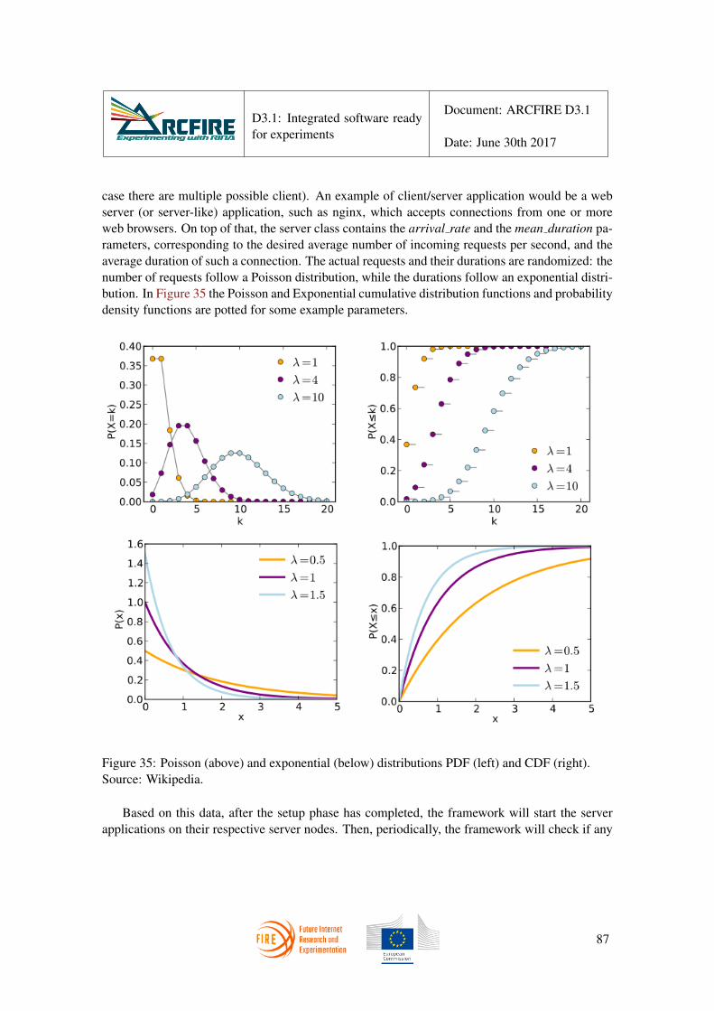
D3.1: Integrated software readyfor experiments
Document: ARCFIRE D3.1
Date: June 30th 2017
case there are multiple possible client). An example of client/server application would be a webserver (or server-like) application, such as nginx, which accepts connections from one or moreweb browsers. On top of that, the server class contains the arrival rate and the mean duration pa-rameters, corresponding to the desired average number of incoming requests per second, and theaverage duration of such a connection. The actual requests and their durations are randomized: thenumber of requests follow a Poisson distribution, while the durations follow an exponential distri-bution. In Figure 35 the Poisson and Exponential cumulative distribution functions and probabilitydensity functions are potted for some example parameters.
Figure 35: Poisson (above) and exponential (below) distributions PDF (left) and CDF (right).Source: Wikipedia.
Based on this data, after the setup phase has completed, the framework will start the serverapplications on their respective server nodes. Then, periodically, the framework will check if any
87

D3.1: Integrated software readyfor experiments
Document: ARCFIRE D3.1
Date: June 30th 2017
server is serving less than its maximum number of concurrent requests. If that is the case, for eachsuch server, a sample from a poisson random variable – with parameter the server’s arrival rate– is drawn. That number of new clients will be started on random client-enabled nodes, and willconnect to the server application. For each of these new clients, its time to live will be determinedas a sample from an exponential random variable with parameter the server’s mean connectionduration. The framework will then check if any client’s time to live is expired and terminate it (ifnecessary).
In this way, the framework will emulate a live network, with connections starting and stoppingall over the net at configurable rates. Hence the framework can be used for stability testing, throughlong-running experiments over a great number of nodes, or for resiliency testing, by interactingwith the testbed while the experiment is running and shutting down a node or a link, in order tocheck the prototypes capability to deal with network failures.
Figure 36: Example Rumba network with Servers, clients and apps
In Figure 36 we can see an example Rumba network, where the server nodes are the bluesquares, the client nodes are yellow, and the running applications are depicted with small colouredsquares. Lastly, the grey nodes are just transport nodes, on which no application (server or client)is run. A storyboard which could lead to such a situation is detailed in Listing 9.
c chat = Client("chat client", testbed= tb)
88

D3.1: Integrated software readyfor experiments
Document: ARCFIRE D3.1
Date: June 30th 2017
s1 = Server("chat server", arrival rate=6,mean duration=5, nodes = [a], clients = [c chat],testbed= tb)
c video 1 = Client("video client", options="−−server b"testbed= tb)
s2 = Server("video server", arrival rate=0.1,mean duration=40, nodes = [b], clients = [c video],testbed= tb)
c video 2 = Client("video client", options="−−server c"testbed= tb)
s3 = Server("video server", arrival rate=0.1,mean duration=40, nodes = [c], clients = [c video],testbed= tb)
c web = Client("web client", testbed= tb)s4 = Server("web server", arrival rate=1, mean duration=10, nodes = [d], clients = [c web], testbed= tb)
sb = StoryBoard(exp, 3600, servers = [s1, s2, s3, s4],testbed=tb)
Listing 9: Example storyboard configuration
In the listing, we see that there are four servers: one receiving a lot of short-lived connections(chat server), two with very few, very long-lived connections (video server) and one which is moreaverage all-around (web server). In the figure, we can see the chat server and clients depicted asa small red square, the two video servers and the clients as purple squares and the web serverand clients as green squares. The figure represents a situation close to what one can expect giventhe configuration: many chat clients (3 in the figure), several web clients (2 in the figure) anda few video clients (1 per server). This, although rescaled for readability concerns, is in linewith the average 30 chat clients, 10 web clients and 4 video clients per server expected given theconfiguration parameters.
5 Summary of ARCFIRE enhancements to RINA software
The software inherited by the ARCFIRE project was very rich and complex, nonetheless sev-eral improvement strategies have been designed and followed ranging from the streamlining andoptimization of the low level interaction between the stack and the machine (the use of the sk -buffer struct), the enhancement of the stack itself and the addition of new features, up to contri-butions to the other software involved in the RINA ecosystem (the DMS and the development ofRumba), in order to prepare the environment for the tests which will be run by WP4. All the while,
89

D3.1: Integrated software readyfor experiments
Document: ARCFIRE D3.1
Date: June 30th 2017
WP3 will keep on looking for room for improvement, on top of solving the issues that might bereported by the aforementioned tests.
The following table summarizes the contributions of ARCFIRE’s WP3 to the RINA environ-ment.
IRATI stack
POSIX-like API
Improved Integration with the network device layer
Shim IPCP over WiFi
Support for seamless renumbering
IP over RINA
Released
Released
In testing
Released
In testing
DMS
Closed control loop
DMS Orchestrator
Integration with FOSS and COTS software
Beta
Beta
In development
Rumba Testbed and prototype-agnostic testing facility Released
90

D3.1: Integrated software readyfor experiments
Document: ARCFIRE D3.1
Date: June 30th 2017
List of Figures
1 DMS High level components . . . . . . . . . . . . . . . . . . . . . . . . . . . . 102 Buildroot menuconfig configuration interface . . . . . . . . . . . . . . . . . . . 143 Verification strategy workflow for ARCFIRE: the demonstrator tool. . . . . . . . 184 RINA API client and server workflow for blocking operation. . . . . . . . . . . . 215 Bidirectional mapping between server-side socket API calls to RINA API calls.
This scheme can be used to port existing socket applications to RINA. . . . . . . 286 Client state machine for rina-echo-async. Edge labels show preconditions (if any)
and actions associated to each state transition. . . . . . . . . . . . . . . . . . . . 337 Server state machine for rina-echo-async. On the top the state machine to accept
new client sessions, on the bottom the one to handle a single session. . . . . . . . 348 The rina-gw deamon used for interoperability between RINA networks and TCP/IP
based networks. TCP connections are proxied over RINA flows and the other wayaround. . . . . . . . . . . . . . . . . . . . . . . . . . . . . . . . . . . . . . . . 35
9 Interations between IRATI librina and the /dev/irati virtual character device. 3810 Original IRATI buffer and SKB layout . . . . . . . . . . . . . . . . . . . . . . . 4211 Original and new IRATI pci . . . . . . . . . . . . . . . . . . . . . . . . . . . . 4212 Original and new SDU and PDU data models . . . . . . . . . . . . . . . . . . . 4413 SDU and PDU data models based on common struct du. . . . . . . . . . . . 4414 Transmission workflow for a user SDU, from the application layer down to the
Shim DIF. . . . . . . . . . . . . . . . . . . . . . . . . . . . . . . . . . . . . . . 4815 Reception workflow for a user SDU, from shim IPCP up to the application layer. 5016 Simple use case involving a mobile node and a shim DIF over WiFi . . . . . . . 5117 Example of handover of a mobile node (UE) across different Access Points in the
mobile network DIF. . . . . . . . . . . . . . . . . . . . . . . . . . . . . . . . . 5218 Overview of the Linux wireless subsystem . . . . . . . . . . . . . . . . . . . . . 5319 Architecture of the Shim WiFi datapath. The existing Shim DIF over Ethernet is
reused in full. . . . . . . . . . . . . . . . . . . . . . . . . . . . . . . . . . . . . 5420 Two options for the layer management path of the Shim WiFi. The one on the top
(i.e. implementation with an user-space daemon) has been selected by ARCFIRE. 5521 Design of the Shim WiFi . . . . . . . . . . . . . . . . . . . . . . . . . . . . . . 5622 Interaction between Shim Wifi IPCP Daemon and other IRATI components . . . 5723 State machine controlling attachment to a neighbour in the shim IPCP over WiFi 5924 Sequence of events triggered by an address change in the Namespace Manager . 6325 Sequence of events triggered when the “start using new address” timer fires . . . 6326 Sequence of events triggered when the “deprecate old address” timer fires . . . . 6427 Service model for IP over RINA flows, with application naming conventions . . . 7028 Interaction of RINA modules with the Linux kernel IP stack . . . . . . . . . . . 71
91

D3.1: Integrated software readyfor experiments
Document: ARCFIRE D3.1
Date: June 30th 2017
29 Simple scenario for an IP over RINA flow . . . . . . . . . . . . . . . . . . . . . 7230 RINA device information as displayed by ifconfig command . . . . . . . . . . . 7331 IP routing table containing route through the RINA device . . . . . . . . . . . . 7332 Usage of the commands related to flows between IP network prefixes . . . . . . . 7433 DMS Principles . . . . . . . . . . . . . . . . . . . . . . . . . . . . . . . . . . . 7734 ARCFIRE Evolved DMS . . . . . . . . . . . . . . . . . . . . . . . . . . . . . . 7835 Poisson and Exponential distributions . . . . . . . . . . . . . . . . . . . . . . . 8736 Example Rumba network with Servers, clients and apps . . . . . . . . . . . . . . 88
92

D3.1: Integrated software readyfor experiments
Document: ARCFIRE D3.1
Date: June 30th 2017
List of Acronyms
ABI Application Binary Interface
API Application Programming (orProgrammer’s) Interface
AP Access Point
ARCFIRE Large-scale RINA experimentation onFIRE+ infrastructure
BIOS Basic Input Output System
CDAP Common Distributed Application Protocol
COTS Commercial Off The Shelf
DIF Distributed IPC Facility
DMS Distributed Management System
EFCP Error and Flow Control Protocol
FOSS Free Open Source Software
GNU GNU’s Not Unix
IPC Inter-Process Communication
IPCM IPC Manager
IPCP IPC Process
IP Internet Protocol
IRATI Investigating RINA as an Alternative toTCP/IP
NIC Network Interface Controller
OO Object-Oriented
PCI Protocol Control Information
PDU Protocol Data Unit
POSIX Portable Operating System Interface forUniX
PRISTINE Programmability In RINA for Europeansupremacy of virTualised NEtworks
RIB RINA Information Base
RINA Recursive InterNetworking Architecture
RMT Relaying and Multiplexing Task
SDK Software Development Kit
SDU Service Data Unit
SNMP Simple Network Management Protocol
TCP Transmission Control Protocol
UDP User Datagram Protocol
UE User Equipment
URL Uniform Resource Locator
VLAN Virtual Local Area Network
VM Virtual Machine
93

D3.1: Integrated software readyfor experiments
Document: ARCFIRE D3.1
Date: June 30th 2017
94

D3.1: Integrated software readyfor experiments
Document: ARCFIRE D3.1
Date: June 30th 2017
References
[1] Rina demonstrator github site. [Online]. Available: https://github.com/IRATI/demonstrator
[2] The buildroot web site. [Online]. Available: http://buildroot.org
[3] “IRATI Deliverable D3.4, Third phase integrated RINA prototype for a UNIX-like OS,”Tech. Rep., Feb. 2015. [Online]. Available: http://irati.eu/deliverables-2/
[4] PRISTINE Consortium, “D6.3 consolidated software for the use cases and final report on theuse cases trials and business impact,” PRISTINE deliverable D6.3, October 2016.
[5] (2014, Apr.) The IRATI website. [Online]. Available: http://www.irati.eu
[6] (2016) A RINA light implementation. [Online]. Available: https://github.com/vmaffione/rlite
[7] ARCFIRE consortium, “Design of experimental scenarios; selection of metrics and kpis,”H2020 ARCFIRE deliverable D4.2. Available online at http://ict-arcfire.eu, January 2017.
[8] ——. (2016, December) H2020 arcfire deliverable d2.2: Converged service providernetwork design report. [Online]. Available: http://ict-arcfire.eu
[9] Open NMS - The Management Platform developed under the Open Source Model. [Online].Available: https://www.opennms.org
[10] L. Fallon, J. Keeney, and S. van der Meer, “Using the compa autonomousarchitecture for mobile network security,” in 2017 IFIP/IEEE InternationalSymposium on Integrated Network Management (IM 2017), May 2017. [On-line]. Available: https://www.researchgate.net/publication/317014586 Using the COMPAAutonomous Architecture for Mobile Network Security
[11] D. M. Beazley et al., “SWIG: An easy to use tool for integrating scripting languages with Cand C++,” in Proceedings of the 4th USENIX Tcl/Tk workshop, 1996, pp. 129–139.
[12] “netem - network emulation for the linux traffic control subsystem,” netem documentation.Available online at https://wiki.linuxfoundation.org/networking/netem.
[13] IRATI Github site. [Online]. Available: https://github.com/irati/stack
[14] (2014, Aug.) netperf. [Online]. Available: http://www.netperf.org/netperf/
[15] (2014, Aug.) iperf. [Online]. Available: http://code.google.com/p/iperf/
[16] hostapd: IEEE 802.11 AP, IEEE 802.1X/WPA/WPA2/EAP/RADIUS Authenticator.[Online]. Available: http://w1.fi/hostapd/
95

D3.1: Integrated software readyfor experiments
Document: ARCFIRE D3.1
Date: June 30th 2017
[17] Linux WPA/WPA2/IEEE 802.1X Supplicant. [Online]. Available: http://w1.fi/wpasupplicant/
[18] N. Montavont, A. Blanc, and R. Navas, “Handover triggering in ieee 802.11 networks,”in Proceedings of IEEE World of Wireless, Mobile and Multimedia Networks (WoWMoM),2015.
[19] F. Baker, E. Lear, and R. Droms, “Procedures for renumbering an ipv6 network without aflag day,” IETF Network Working Group RFC 4192, September 2005.
[20] E. Evans, Domain-Driven Design: Tackling Complexity in the Heart of Software. AddisonWesley, 2003.
[21] M. Fowler, Domain Specific Languages. Addison-Wesley, Sep. 2010.
[22] (2016, Jan.) The IRATI configurator. [Online]. Available: https://github.com/irati/configurator
[23] (2017, May) The qemu website. [Online]. Available: http://www.qemu.org/
96
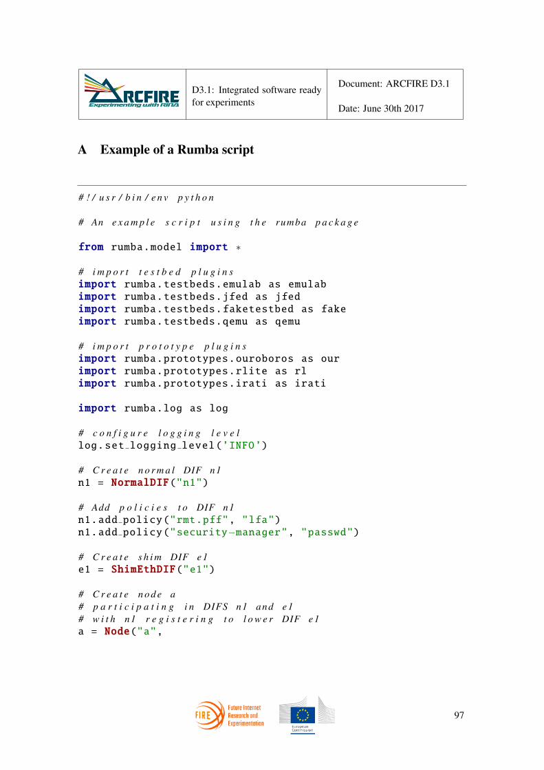
D3.1: Integrated software readyfor experiments
Document: ARCFIRE D3.1
Date: June 30th 2017
A Example of a Rumba script
# ! / u s r / b i n / e n v p y t h o n
# An e x a m p l e s c r i p t u s i n g t h e rumba p a c k a g e
from rumba.model import ∗
# i m p o r t t e s t b e d p l u g i n simport rumba.testbeds.emulab as emulabimport rumba.testbeds.jfed as jfedimport rumba.testbeds.faketestbed as fakeimport rumba.testbeds.qemu as qemu
# i m p o r t p r o t o t y p e p l u g i n simport rumba.prototypes.ouroboros as ourimport rumba.prototypes.rlite as rlimport rumba.prototypes.irati as irati
import rumba.log as log
# c o n f i g u r e l o g g i n g l e v e llog.set logging level(’INFO’)
# C r e a t e n o r m a l DIF n1n1 = NormalDIF("n1")
# Add p o l i c i e s t o DIF n1n1.add policy("rmt.pff", "lfa")n1.add policy("security−manager", "passwd")
# C r e a t e s h i m DIF e1e1 = ShimEthDIF("e1")
# C r e a t e n o d e a# p a r t i c i p a t i n g i n DIFS n1 and e1# w i t h n1 r e g i s t e r i n g t o l o w e r DIF e1a = Node("a",
97

D3.1: Integrated software readyfor experiments
Document: ARCFIRE D3.1
Date: June 30th 2017
difs = [n1, e1],dif registrations = {n1 : [e1]})
# C r e a t e c l i e n t n o d e bb = Node("b",
difs = [e1, n1],dif registrations = {n1 : [e1]},client = True)
# C r e a t e t h e t e s t b e d p r o v i d i n g i t s c o n f i g u r a t i o ntb = jfed.Testbed(exp name = "example1",
username = "user1",cert file = "/home/user1/cert.pem")
# C r e a t e an I R A T I e x p e r i m e n texp = irati.Experiment(tb, nodes = [a, b])
# Show t h e e x p e r i m e n t ’ s l o g i c a l s t r u c t u r eprint(exp)
try:# R e s e r v e r e s o u r c e s on t h e t e s t b e dexp.swap in()# I n s t a l l I R A T I on t h e n o d e sexp.install prototype()# S e t u p and s t a r t I R A T I on t h e n o d e sexp.bootstrap prototype()# The c l i e n t a p p l i c a t i o n i s r i n a p e r fc1 = Client("rinaperf", options ="−t perf −s 1000 −c10000")
# r i n a p e r f w i t h o p t i o n ’− l ’ r u n s i n s e r v e r modes1 = Server("rinaperf", arrival rate=2, mean duration=5, options = "−l", nodes = [a], clients = [c1])
# S t a r t a t e s t w i t h a d u r a t i o n o f o n e h o u r ( 3 6 0 0 s )sb = StoryBoard(exp, duration=3600, servers = [s1])sb.start()
finally:# R e l e a s e t h e r e s o u r c e s on t h e t e s t b e dexp.swap out()
98

D3.1: Integrated software readyfor experiments
Document: ARCFIRE D3.1
Date: June 30th 2017
rumba example.py
99