Obstacle Avoidance Control on Omnidirectional Vehicle Robots Using Range Sensor
9
Extended Summary 本文は pp.849–856 Obstacle Avoidance Control on Omnidirectional Vehicle Robots Using Range Sensor Akira Shimada Senior Member (Dept. of Electrical System Engineering, Polytechnic University Hashimotodai, 4-1-1, Sagamihara-shi, Kanagawa, Japan) Prasarn Kiddee Non-member (Dept. of Electrical System Engineering, Polytechnic University Hashimotodai, 4-1-1, Sagamihara-shi, Kanagawa, Japan) Yujiro Nishi Non-member (Faculty of Engineering Kyushu University, Motooka 744, Nishi-ku, Fukuoka-shi, Fukuoka, Japan) Keywords: omnidirectional vehicle, mecanum wheel, collision avoidance, scanner range sensor Generally, intelligent vehicle robots are strongly needed in many fields. They are expected to assist our daily lives. In order to de- velop the robots in practice, controllers of the robots should have useful function including path planning, navigation, and obstacle avoidance etc. This paper focuses on an obstacle avoidance control technique for omunidirectional vehicle robots. The used vehicle as a platform is a mecanum wheel omnidirectional vehicle which is driven on floors and mounts a scanner range sensor. The obsta- cle avoidance control is excuted as a position based mechanical im- peedance control law, and it can be handled to multiple obstacles. Finally, an experimental result is shown in order to evaluate the pre- sented control method. Fig. 1 illustrates the outview of vehicle and snanner range sensor. Fig. 1. Outview of vehicle and scanner range sensor (a) Scanner range sensor and obstacles detection (b) Image of decision process Fig. 2. Obstacle detection and decision method of an avoidance angle/distance The scanner sensor is set on the front face of the vehicle and the sensor detects obstacles. Fig. 2(a) illustrates the function of vehicle controller using the scanner range sensor. The sensor recognizes the number of obstacles and the directions of them. Furthermore, (b) il- lustrates the image of distance and direction decision process. The left figure describes the vectors which indicate distances between the positions of obstacles and the radius th which is a threshold. The right figure illustrates sum of the vectors and the inverse vector. The inverse vector indicates the direction of vehicle obstacle avoid- ance. It means that the sum of vector indicates a virtual obstacle as a representative of all of obstacles. Fig. 3 shows the experimental result. They show the sequential photographs of the movement with obstacle avoidance. (a) t = 1s (b) t = 4s (c) t = 6s (d) t = 7s (e) t = 9s (f) t = 10 s (g) t = 12 s (h) t = 14 s Fig. 3. Sequential photographs of Experiment –21–
Transcript of Obstacle Avoidance Control on Omnidirectional Vehicle Robots Using Range Sensor

Extended Summary 本文は pp.849–856
Obstacle Avoidance Control on OmnidirectionalVehicle Robots Using Range Sensor
Akira Shimada Senior Member (Dept. of Electrical System Engineering, Polytechnic UniversityHashimotodai, 4-1-1, Sagamihara-shi, Kanagawa, Japan)
Prasarn Kiddee Non-member (Dept. of Electrical System Engineering, Polytechnic UniversityHashimotodai, 4-1-1, Sagamihara-shi, Kanagawa, Japan)
Yujiro Nishi Non-member (Faculty of Engineering Kyushu University,Motooka 744, Nishi-ku, Fukuoka-shi, Fukuoka, Japan)
Keywords: omnidirectional vehicle, mecanum wheel, collision avoidance, scanner range sensor
Generally, intelligent vehicle robots are strongly needed in manyfields. They are expected to assist our daily lives. In order to de-velop the robots in practice, controllers of the robots should haveuseful function including path planning, navigation, and obstacleavoidance etc. This paper focuses on an obstacle avoidance controltechnique for omunidirectional vehicle robots. The used vehicle asa platform is a mecanum wheel omnidirectional vehicle which isdriven on floors and mounts a scanner range sensor. The obsta-cle avoidance control is excuted as a position based mechanical im-peedance control law, and it can be handled to multiple obstacles.Finally, an experimental result is shown in order to evaluate the pre-sented control method.
Fig. 1 illustrates the outview of vehicle and snanner range sensor.
Fig. 1. Outview of vehicle and scanner range sensor
(a) Scanner range sensor and obstacles detection
(b) Image of decision process
Fig. 2. Obstacle detection and decision method of anavoidance angle/distance
The scanner sensor is set on the front face of the vehicle and thesensor detects obstacles. Fig. 2(a) illustrates the function of vehiclecontroller using the scanner range sensor. The sensor recognizes thenumber of obstacles and the directions of them. Furthermore, (b) il-lustrates the image of distance and direction decision process. Theleft figure describes the vectors which indicate distances betweenthe positions of obstacles and the radius th which is a threshold.The right figure illustrates sum of the vectors and the inverse vector.The inverse vector indicates the direction of vehicle obstacle avoid-ance. It means that the sum of vector indicates a virtual obstacle asa representative of all of obstacles. Fig. 3 shows the experimentalresult. They show the sequential photographs of the movement withobstacle avoidance.
(a) t = 1 s (b) t = 4 s
(c) t = 6 s (d) t = 7 s
(e) t = 9 s (f) t = 10 s
(g) t = 12 s (h) t = 14 s
Fig. 3. Sequential photographs of Experiment
– 21 –

論 文
測域センサを用いた全方向移動ロボットの障害物回避制御
上級会員 島田 明∗ 非会員 プラサーン キッディ∗
非 会 員 西祐 二郎∗∗
Obstacle Avoidance Control on Omnidirectional Vehicle Robots Using Range Sensor
Akira Shimada∗, Senior Member, Prasarn Kiddee∗, Non-member, Yujiro Nishi∗∗, Non-member
Generally, intelligent vehicle robots are strongly needed in many fields. They are expected to assist our daily lives.
In order to implement them in practice, we should mount useful functions including path planning, navigation, and ob-
stacle avoidance, etc. on the robots. This paper focuses on obstacle avoidance control technique to multiple obstacles.
The used vehicle as a platform is the mecanum wheel omnidirectional vehicle which is driven on floors and mounts a
scanner range sensor. The presented algorithm has the feature that multiple obstacle avoidance control is simply come
down to the mono-obstacle avoidance control scheme. Finally, the experimental results are shown in order to evaluate
the presented algorithms.
キーワード:全方向移動車,メカナムホイール,障害物回避制御,スキャナ型測域センサ
Keywords: omnidirectional vehicle, mecanum wheel, collision avoidance, scanner range sensor
1. はじめに
自律機能を持つ車輪型移動ロボットは,様々な分野で,
人や荷物の運搬等に用いることが期待されている。これまでにも多くの研究成果が報告され (1)~(4),特集解説が企画され (5),著書も出版されてきた (6) (7)。しかしながら,その機能や性能をさらに高めるためには,行動計画,ナビゲーショ
ン,障害物回避等の要素技術をより高度化すると共に,システムの高度化に向けた継続的な研究が必要である。行動計画はロボットが所望の作業を遂行するための行動の順番と内容を決定することである。ナビゲーションは航
海術のことであり,1)位置・姿勢の推定,2)経路探索,3)誘導制御に分類できる。また,障害物回避は既知の障害物を回避する技術と未知の障害物を回避する技術とに分けられる。既知の障害物を回避する機能や比較的長い時間をかけ
て逐次行うことができる障害物回避は経路探索技術に含めて考えることもできる。このような環境の下で,本研究は,室内で走行する全方向移動車(以下,ビークル)を開発し,
それを実用化することをめざしており,本稿では,複数の
∗ 職業能力開発総合大学校電気システム工学科〒229-1196 相模原市橋本台 4-1-1Dept. of Electrical System Engineering, Polytechnic University4-1-1, Hashimotodai, Sagamihara
∗∗ 九州大学大学院システム情報科学研究院〒819-0395 福岡市西区元岡 744 番地Faculty of Engineering, Kyushu University744, Motooka, Nishi-ku, Fukuoka
未知の障害物に対する障害物回避制御技術の一実現法を提
案することを目的としている。障害物回避制御の研究は,(a) 可視グラフ法,(b) セル分割法,(c) 人工ポテンシャル法等の多くの方法が知られており (1) (6),(c)に属する方法として,仮想的な弾性や機械
インピーダンス特性を仮定した動作計画法も提案されている (2) (8) (9)。例えば,Khatibの方法 (1)は,目標コンフィグレーションからの引力ポテンシャルと障害物からの斥力ポテンシャルを定義し,総合的に得られる仮想的な力をロボット
に与えるように動作を決定する。また,新井・太田らの動作計画法 (2) は,複数の障害物やビークルが存在する環境下で,各障害物に対する仮想インピーダンスを仮定する方法であり,妨害を定義し,停留回避まで考慮している等,完成
度の高い研究例として知られている。本稿も仮想機械インピーダンスを仮定する等,大筋では既存技術の枠内に留まる。しかしながら,提案方法は,複数障害物の各々に対する機械インピーダンスを仮定するのではなく,ビークルと
複数の障害物との相対位置から,複数の障害物を代表する仮想的な単一の障害物(以降,仮想代表障害物と呼ぶ)を仮定し,障害物回避制御問題を仮想代表障害物への位置ベース仮想機械インピーダンス制御に帰着させる点に特徴を有
する。従来法に比べて同程度の性能ではあるが,考え方が単純なため,実装し易い一構成法として価値があると思われる。
本稿の具体的内容は,Fig. 1左図に示すスキャナ型測域センサ (10)を搭載した右図のビークルを試作し,同制御法の
c© 2008 The Institute of Electrical Engineers of Japan. 849

Fig. 1. Outview of the omnidirectional vehicle andscanner range sensor
設計プロセスを示し,評価実験の結果を紹介するものである。同ビークルは,メカナムホイールと呼ばれる車輪を用いている (13) (14)。スキャナ型測域センサを応用する研究につ
いても,いくつもの研究例 (12) が報告されているが,提案する制御法そのものを全方向移動車に実装した例はないようである。以上から,本稿の内容は産業応用分野にとって有用性を持つものと思われる (11)。
2. 障害物回避制御系の設計
〈2・1〉 障害物回避制御系の基本構成 システムは,(a)経路探索に基づく軌道参照値の生成部と,(b)未知の障害物を回避するための軌道修正部と,(c)位置追従制御系の 3
要素から構成される。Fig. 2はそれを図示したものであり,Planning & Simulationが (a)を,Position Based Mechanical
Impedance Feedfoward Controlが (b)を,Vehicle Position
Control Systemが (c)を表す。点線枠はスキャナ型測域センサの機能を表し,ビークルから障害物への相対位置を出力し,軌道修正は同出力に基づいて行われる。従来,太田らが (a),(b)とほぼ同様の機能をGlobal Motion Planner及
び Local Avoidance Plannerと名づけており (2),他の文献でも類似の名称が使われているようであるが,制御系設計の観点から同要素を考えている点と,全く等価な構造でもないようなので上記の表記を用いておく。
〈2・2〉 座標系の定義と障害物の位置・姿勢 座標系の定義を行う。まず,Fig. 3に示すように,床座標系 ΣF,ビークル座標系 ΣV,そして各車輪の回転中心に車輪座標系
ΣiW,i = 1 ∼ 4を定義する。床座標系はビークルが移動する世界を表すワールド座標系でもあるが,座標の固定先を具体的に示すために,そのように定義する。車輪座標系については次節で触れる。Fig. 4は床座標系 ΣF 及びビークル
座標系 ΣV 上でのビークル(円)と障害物(×)との相対関係を表す。英文字の左上の添え字はベースとなる座標系を,右下の添え字の veはビークルを,obは障害物を表す。運用時には,未知の複数の障害物が接近するが,後述する
ように,全ての障害物を仮想的な単一の点で代表させる。床座標系のビークル位置を F Pve = [F xve, Fyve,
Fθve],障
Fig. 2. Basic structure of control system
Fig. 3. Relation between the coordinate frames of vehi-cle
Fig. 4. Relation between vehicle and representative ob-stacle
害物の位置を F Pob = [F xob,Fyob,
Fθob]と表す。但し,第3要素は姿勢を表す。また,本稿では研究の初期段階とし
て,障害物の姿勢は扱わないので,便宜上,Fθob = 0としておく。さらに,ビークル中心から障害物に向けた直線をVOX座標軸,反時計回り π/2方向を VOY とする VO座標系ΣVO を定義する。VOX 軸の床座標系 ΣF から見た姿勢 Fθvo
は (1)式で,ビークル座標系 Σv上では (2)式で表され,VO
座標系における障害物の位置 VOPは (3)式,または,(4)式で表される。VOxob 値は常に正である。
FθVO = atan2(Fyob − Fyve,F xob − F xve) · · · · · · · · · · (1)
Vθvo = atan2(Vyob,V xob) · · · · · · · · · · · · · · · · · · · · · · · · (2)
850 IEEJ Trans. IA, Vol.128, No.6, 2008

全方向移動ロボットの障害物回避
VOxob =
√(F xob − F xve)2 + (Fyob − Fyve)2 · · · · · · · (3)
=
√V x2
ob +Vy2
ob · · · · · · · · · · · · · · · · · · · · · · · · · · (4)
〈2・3〉 単数の障害物に対する回避アルゴリズム 定義より,単一の障害物は常に VOx軸上にあり,障害物回避を 1次元運動で扱うことができる。そこで Fig. 5を考える。図の thはビークルからの距離の閾値(threshold)を意味し,
障害物が th より遠いと回避をせず,近いと障害物の位置voxob と thとの間の距離に応じた回避制御を行う。ビークルと障害物の距離でないことに注意されたい。具体的には,(c)~(d)図のように,ビークルと障害物の間に仮想的な弾
性と粘性があり,ビークルが仮想的な質量を持つ質点のように制御を行う。(c)図では障害物が th位置よりビークルに近づいてバネが縮み,ビークルが移動して (d)図の平衡状態に至る。仮想的な質量 mv,粘性係数 dv,弾性係数 kvとし,制御則を (5),(6)式を用いて Fig. 6のように表す。ρは回避距離である。これらの関係式に相対距離の逆数を用いる方法も知られているが (2) (7),本稿では,閾値と障害物との距離を利用し,複数の障害物に対して拡張する。
e = VOxob − th · · · · · · · · · · · · · · · · · · · · · · · · · · · · · · · · · · (5)
mvρ =
⎧⎪⎪⎨⎪⎪⎩+kv(e − ρ) − dvρ if e < 0
−kvρ − dvρ if e ≥ 0· · · · · · · · · · · · (6)
Fig. 6(a)図はビークルと障害物の位置を直接に観測する
場合の軌道修正部のブロック図である。√
e2x + e2
y演算部で
はビークル・障害物間距離が算出され,点線枠内は仮想機械インピーダンス特性を表す。(6)式の回避距離 ρを演算する機能である。非線形ブロックは閾値 th との偏差が正
値ならば零値を,負値ならば偏差を出力し,障害物回避を行うか否かを切り替える。出力 F xrev,
Fyrev は,軌道参照値F xr,
Fyr に対し,障害物に対する修正値を加えた修正参照値である。atan2演算部は障害物の角度を −πから πの範囲で算出し,cos,sin演算結果が,回避距離 VOxve と ⊗部で各々乗算され,修正値の x,y成分を算出する。これに対して (b)図は,スキャナ型測域センサを用いて,障害物のビークル座標系での距離 VOxobと角度 Vθvoを観測する場合
を表す。波線枠内は (a)図と同じであり,Fig. 4を参考に,床座標系とビークル座標系の相対角度 FθV を加算すれば,(a)図と等価な機能となる。
〈2・4〉 ビークルのモデリング ビークルの物理パラメータを表す変数の定義を Table 1に示す。メカナムホイールは,16個のフリーホイールが車輪の外周に等間隔に,その回転軸が外周に対してπ/4 radの角度を保つように配置さ
れる。Fig. 7参照のこと。ビークルの速度はホイールとフリーホイールの回転による協調運動によって定まる。Fig. 3
に即して幾何学的に考察すると,i = 1 ∼ 4に対し,各車輪の iW X方向速度 ViX は,車輪回転による速度 ViW (= rθi)と
フリーホイールの転がりによる速度Vir により,iWY 方向速度 ViY は Vir により定まる。同時に,ViX はビークルの V X
Fig. 5. Idea of obstacle avoidance making use of virtualmechanical impedance
(a) Floor coordinate based control
(b) Vehicle coordinate based control
Fig. 6. Block diagram of virtual mechanical impedancefeedfoward control system
Table 1. Physical variables of vehicle
Total mass of vehicle, wheel, m
and equivalent mass of rotor inertia
Moment of inertia of vehicle, wheel Iz, Iw
Radius of wheel r
Generalized coordinate F Pve = [F xve, Fyve, Fθve]T
Generalized force F = [Fx, Fy, τz]T
Angle vector of wheel θw = [θ1, · · · , θ4]T
Torque vector of wheel τ = [τ1, · · · , τ4]T
Coefficient of wheel viscous friction Cθ
Fig. 7. Outview of mecanum wheel
電学論 D,128 巻 6 号,2008 年 851

Fig. 8. Model of vehicle expressed on floor coordinatespace
方向速度 V xveと回転速度 V θveにより定まり,ViY はビーク
ルの V Y 方向速度 V yveと V θveにより定まる。この関係を連立させて,ViX,ViY,Vir を消去すると,以下が得られる。各係数行列は一種のヤコビ行列である。
F P = F Jw · θw = (F JV · V Jw) · θw · · · · · · · · · · · · · · · · · (7)
θw =wJF · F P = (V J+w · F J−1
V )F P · · · · · · · · · · · · · · · · · (8)
但し,F JV =
⎡⎢⎢⎢⎢⎢⎢⎢⎢⎢⎢⎣cosFθve −sinFθve 0
sinFθve cosFθve 0
0 0 1
⎤⎥⎥⎥⎥⎥⎥⎥⎥⎥⎥⎦,
vJw =Rw4
⎡⎢⎢⎢⎢⎢⎢⎢⎢⎢⎢⎣1 1 1 1
−1 1 1 −1
−1/α 1/α −1/α 1/α
⎤⎥⎥⎥⎥⎥⎥⎥⎥⎥⎥⎦α = L+ l。L,lは前後及び左右の車輪間距離の 1/2。ビークルの運動エネルギー K,ポテンシャルU と散逸関数 Bは
(9),(10),(11)式のように表される。
K =12
mF x2ve +
12
mF y2ve +
12
IzF θ2ve
+12
Iw(θ21 + θ22 + θ
23 + θ
24) · · · · · · · · · · · · · · · · · · · · (9)
U = 0 · · · · · · · · · · · · · · · · · · · · · · · · · · · · · · · · · · · · · · · · (10)
B =12
Cθ(θ21 + θ
22 + θ
23 + θ
24) · · · · · · · · · · · · · · · · · · · (11)
(8)式を (9),(10)式に代入し,ラグランジュの運動方程式を解くと,一般化座標による (12)式が得られる。
MFF Pve +CF
F Pve = F · · · · · · · · · · · · · · · · · · · · · · · · (12)
但し,慣性行列 MF,粘性摩擦係数行列 CF として,
MF =
⎡⎢⎢⎢⎢⎢⎢⎢⎢⎢⎢⎣m1 0 0
0 m1 0
0 0 m2
⎤⎥⎥⎥⎥⎥⎥⎥⎥⎥⎥⎦,CF =
⎡⎢⎢⎢⎢⎢⎢⎢⎢⎢⎢⎣c1 0 0
0 c1 0
0 0 c2
⎤⎥⎥⎥⎥⎥⎥⎥⎥⎥⎥⎦,m1 = m+4Iw/r2,m2 = Iz+4α2Iw/r2,α = L+l,c1 = 4Cθ/r2,c2 = 4Cθα2/r2 であり,F = [ fx, fy, mz]T は一般化力である。また,(12)式から次式が得られる。
F Pve = M−1F F − M−1
F CFF Pve · · · · · · · · · · · · · · · · · · · (13)
仮想仕事の原理より,車輪の駆動トルク τ = [τ1, τ2, τ3,
τ4]T と一般化力 F の関係は τ = wJTF · F で表されるため,
(13)式の制御対象は Fig. 8のように表される。wJ+TF は wJT
F
の擬似逆行列,Fr = [ frx, fry, mrz]T は一般化力参照値である。トルク τを入力としたのは,実機がモータのトルク制
御に基づき駆動されるためである。従って,その左に F JTw
演算部を挿入すれば,一般化力で制御するシステムとなる。
Fig. 9. Block diagram of the control system
〈2・5〉 ビークルの追従制御系 前節の制御対象に対
し,軌道修正部を参照値とし,追従制御系を設計するとFig. 9
が得られる。図中のVeicle expressed ∼ spaceが Fig. 8に相当する。制御系設計手順は次の通り。Step 1) 制御対象の状態空間モデルの作成:状態変数 x =
[F PTve,
F PTve]T,入力 u = Fr,出力 y = F PT
veとし,(13)式用い,次の状態方程式 (14)と出力方程式 (15)を得る。
x = Ax + Bu · · · · · · · · · · · · · · · · · · · · · · · · · · · · · · · · · (14)
y = Cx · · · · · · · · · · · · · · · · · · · · · · · · · · · · · · · · · · · · · · · (15)
但し,A =
⎡⎢⎢⎢⎢⎢⎣ 03×3 I3
03×3 −M−1F CF
⎤⎥⎥⎥⎥⎥⎦ ∈ R6×6,
B =
⎡⎢⎢⎢⎢⎢⎣ 03×3
M−1F
⎤⎥⎥⎥⎥⎥⎦ ∈ R6×3,C =[
I3 03×3
]∈ R3×6。
Step 2)制御系設計:偏差 ye = [yr−y]T ∈ R3とし,yeの積分
値を we とする。参照値 rをステップ状と仮定すると r = 0
である。ye = r − F Pve = −F Pve,we = yeとなる。(14)式の第 2行を抜き出し,新たな状態変数 x = [F Pve, ye, we]T と
して,次の 9次の拡大系を作成する。
ddt
⎡⎢⎢⎢⎢⎢⎢⎢⎢⎢⎢⎣F Pveye
we
⎤⎥⎥⎥⎥⎥⎥⎥⎥⎥⎥⎦ =⎡⎢⎢⎢⎢⎢⎢⎢⎢⎢⎢⎣−M−1
F CF 0 0
−I 0 0
0 I 0
⎤⎥⎥⎥⎥⎥⎥⎥⎥⎥⎥⎦
⎡⎢⎢⎢⎢⎢⎢⎢⎢⎢⎢⎣F Pveye
we
⎤⎥⎥⎥⎥⎥⎥⎥⎥⎥⎥⎦
+
⎡⎢⎢⎢⎢⎢⎢⎢⎢⎢⎢⎣−M−1
F
0
0
⎤⎥⎥⎥⎥⎥⎥⎥⎥⎥⎥⎦ u · · · · · · · · · · · · · · · · · (16)
(17)式の評価関数を最小にする最適制御則を用いると,uは(18)式で表され,積分して (19)式が得られる。QM ∈ R9×9,
RM ∈ R3×3 は準正定及び正定な重み行列である。
JM =
∫ ∞0
(xT QM x + uT RMu)dt · · · · · · · · · · · · · · · · (17)
u = −F x = −K1F Pve − K2ye − K3we · · · · · · · · · · · (18)
u = −K1F Pve − K2ye − K3
∫ t
0yedt · · · · · · · · · · · · (19)
K1 = −KD,K2 = KP,K3 = −KI とおくと,(20)式が得
られ,多入力多出力型の PI-D制御系となる。
u = KPye + KI
∫ t
0yedt − KD
F Pve · · · · · · · · · · · · · · (20)
実際には,Fig. 9のように構成すれば良い。Fig. 9の F Prev
は,yr = [ρx, ρy, ρz(= 0)]T と軌道参照値 F Pr の加算値である。F Pr は滑らかな関数として設計する。
852 IEEJ Trans. IA, Vol.128, No.6, 2008

全方向移動ロボットの障害物回避
3. 複数障害物の検出法と回避方向・距離の決定
〈3・1〉 仮想代表障害物の向きの決定 複数の障害物に対する回避制御のフローを Fig. 10に示す。Step 1)システムの初期化後,経路に沿った移動を開始し,Step 2)走行中に,逐次に,障害物の数を数え,各障害物の
向きと距離データを保存し,Step 3)最も近い障害物との距離データを保存し,Step 4)複数障害物を代表する仮想代表障害物を仮定し,同障害物に対して,前節の障害物回避制御を行う。
Fig. 11の (a)図に,スキャナ型測域センサの障害物検出のイメージを示し,(b) 図に仮想代表障害物の向きの導出手順を示す。(a)図では,センサが観測領域を N + 1分割
し,i = 0 ∼ N 毎にレーザ線を遮るまでの距離を観測する。網掛け部分がレーザ線が通る領域であり,レーザ線が壁とj − 1 個の障害物で遮られる。円弧半径が闘値 th を表し,障害物までの距離が円弧内であれば,ビークルは障害物と
認識する。闘値 th以下のデータが連続する間は障害物が 1
個あると見なす。Obstacle2のように凹状の形状を有する
Fig. 10. Decision flow of direction and distance for ob-stacle avoidance
(a) Scanner range sensor and obstacles detection
(b) Image of decision process
Fig. 11. Obstacle detection and decision method of anavoidance angle/distance
物体が近づき,窪み部分が円弧外に残る場合は障害物が 2
個あるものと認識する。1障害物の闘値 th以下のデータが
続くうちの最小データを同障害物への距離 V Xobi とし,そのときのデータから座標値 {V xobi,
Vyobi}を求める。また,(b)図に,センサ座標系 Σs{V X′, V Y ′}を記したが,ビークル座標系 ΣV とのずれが無視できる場合は V X′ = V X とす
る。無視できない場合は,適宜,座標変換を行う。仮想代表障害物の角度 Vθobの決定法として,障害物の数を認識した後,ビークルと各障害物までの最短距離 V Xobi とその座標 {V xobi,
Vyobi}を得る。V Xobi値と闘値 thとの差を eiとし
て (21)式に表す。障害物の角度 Vθobi は測域センサから得るが,他の外部センサを用いる場合には (22)式を用いる。ei と Vθobi を (23)式に代入し,障害物と円弧とを結ぶベクトル((b)図内の実線矢印)の Xthi 成分,Ythi 成分を得る。
次に,(b)右図のように,各 Xthi,Ythiデータをセンサ座標原点を始点として全てを (24),(25)式のように加算し,(26)
式を用いて求めた角度を仮想代表障害物の向き Vθobと定める。極めて人為的な規則だが,全障害物の距離を考慮し,障
害物と閾値 thの円弧との距離を用いることにより,ビークルに近い障害物ほど大きな値が加算され,回避に強く反映される性質を持たせる意味を有する。
ei = th − voXobi (i = 1, 2, 3, · · · , j − 1) · · · · · · · · · (21)
vθobi = atan2(vyobi,vxobi) · · · · · · · · · · · · · · · · · · · · · · · (22)
Xthi = cosθobi · ei, Ythi = sinθobi · ei · · · · · · · · · · · (23)
allXob = Xth1 + Xth2 + · · · + Xth, j−1 · · · · · · · · · · · · · (24)
allYob = Yth1 + Yth2 + · · · + Yth, j−1 · · · · · · · · · · · · · · (25)
Vθob = atan2(allYob, allXob) · · · · · · · · · · · · · · · · · · · (26)
〈3・2〉 仮想代表障害物への距離と大きさの検討 仮想代表障害物までの距離を定める。最も単純な方法の一つは,最も近い障害物の距離を仮想代表障害物の距離とする方
法である。Fig. 11(b)は同法に即して描いた。次に,障害物の大きさを反映する可能性を探る。Fig. 12のように,センサが閾値内の i = jから i = j + kまでステップ数 stepi = k
の大きさの障害物を認識するものとする。これは障害物の
実質的な大きさでなく,ビークルの動作を遮る影響を評価する意味を持つ。ビークルから障害物までの距離 voXobi と
Fig. 12. Considering size of obstacle
電学論 D,128 巻 6 号,2008 年 853
して (27)式を定める。δ (> 0)は適当なゲインとする。
hi = k · δ(th − voXobi) · · · · · · · · · · · · · · · · · · · · · · · · · · (27)
同式は閾値 thから障害物まで距離と step数 kとの積,すなわち,面積を求めることになり,近くて大きい障害物の
hi 値が大きなり,遠く小さい障害物の hi 値が小さくなる。同計算を全障害物に行い,hi 値の加算値を用いて,仮想障害物までの距離を決める等が考えられる。但し,本稿では提案のみに留め,最っも近い障害物の距離を voXob とする。
4. 実機の基本構成
研究に用いるビークルはメカナムホイールをビークルの四隅に配置するが (13) (14),提案技術の適用は同ホイールに限定されない。ビークルの位置認識は,同ホイールを駆動す
るサーボモータに接続されるロータリーエンコーダの出力パルスをカウントすることにより行う,いわゆる,デッドレコニング法に属するが,位置認識手段をデッドレコニング法に限る必要はなく,外部センサ等で位置認識を行えば,
より正確な位置制御が期待できる。外部センサ等を用いてロボットの絶対位置・姿勢を認識する技術は Localization
とも呼ばれて,研究が盛んであるが本稿では扱わない (6)。
障害物の認識は,ビークルの前方にスキャナ型測域センサで行う。本稿では側方や後方から接近する障害物には言及しないが,前方での障害物回避方法は側方や後方に拡張できるため,必ずしも一般性を失うものではない。
Table 2. Parameters of range sensor
Model URG-04LX (Hokuyo Automatic Co., Ltd.)
Illuminant Semiconductor laser λ = 785 (nm)
Range 20~4095 (mm), 240 × 2π/360 (rad)
Resolution 2π/1024 (rad)
Scanning time: Tl 100 (ms)
Interface USB, RS232C (19.2 kbps~750 kbps)
Table 3. Physical parameters of the vehicle
Distance half length: L, l 0.23 (m), 0.25 (m)
Mass of vehicle: m 109 (kg)
Radius of wheel: Rw 0.115 (m)
Planetary gear ratio: n 42
Moment of inertia: Iz 6.307 (kgm2)
Moment of inertia: Iw 0.0256 (kgm2)
Co-ef. of viscus friction: Dwi 39.8 (Nms/rad)
Sampling time: T s 1 (ms)
Table 4. Physical parameters of virtual mechanicalimpedance example
elasticity coefficient: Kv 500 (N/m)
Virtual mass: M 100 (kg)
Coefficient of viscosity: Cv√
4MKv (N/m)
threshold: th 1.2 (m)
Table 5. Control parameters of the platform
Weight function: QM diag(30, 30, 30, 3 × 10³ , 3 × 10³, 3 × 10³,
3 × 10⁵, 3 × 10⁵, 3 × 10⁵)
Weight function: RM diag(1, 1, 1)
ビークルの内部には,RT-Linuxを搭載した組み込みシステム,100 Wの ACサーボモータ及びモータドライバ各 4
台,バッテリ,DC-ACコンバータが搭載される。また,スキャナ型測域センサの主な仕様を Table 2に示した。4行目の数値 1024が大きいほど観測の分解能が上がる。
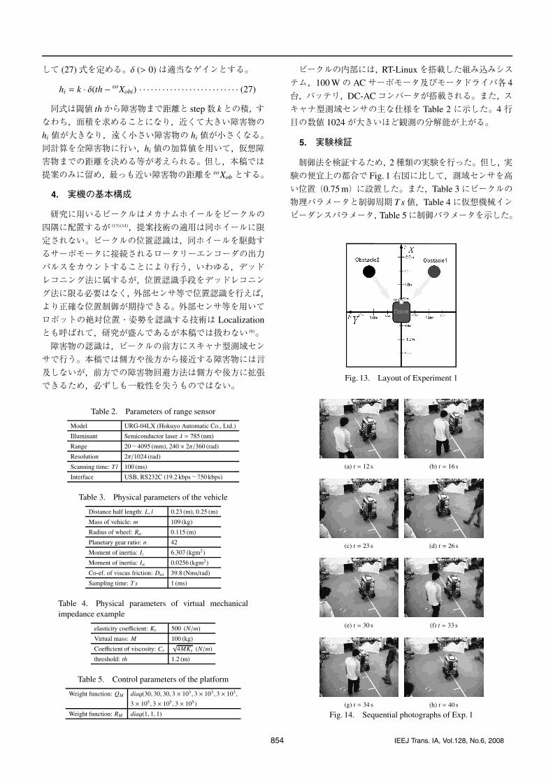
5. 実験検証
制御法を検証するため,2種類の実験を行った。但し,実験の便宜上の都合で Fig. 1右図に比して,測域センサを高
い位置(0.75 m)に設置した。また,Table 3にビークルの物理パラメータと制御周期 T s値,Table 4に仮想機械インピーダンスパラメータ,Table 5に制御パラメータを示した。
Fig. 13. Layout of Experiment 1
(a) t = 12 s (b) t = 16 s
(c) t = 23 s (d) t = 26 s
(e) t = 30 s (f) t = 33 s
(g) t = 34 s (h) t = 40 s
Fig. 14. Sequential photographs of Exp. 1
854 IEEJ Trans. IA, Vol.128, No.6, 2008

全方向移動ロボットの障害物回避
Fig. 15. Experimental result 1
Fig. 16. Layout of Experiment 2
〈5・1〉 実験 1:複数障害物の回避 複数の人を障害物
に見立て,静止したビークルに接近する実験を行う。Fig. 13
にレイアウトを示し,Fig. 14に実験の様子を写真で示す。Fig. 14の 2人の人物が Fig. 13のObstacle1,2に相当する。1) Obstacle1がビークルに接近して離れ,2)次にObstacle2
がビークルに接近して離れ,3)最後に,両者が同時にビークルに接近して離れる。その結果,1人がビークル斜め前方から接近する時は,ビークルが反対の斜め後方に回避し,
2人がビークルに接近するときは,仮想代表障害物の導出法に基づき,後方に回避する様子が読み取れる。Fig. 15の1段目は全ての障害物のうちの最短距離 VOxob を,2段目は仮想代表障害物への角度を表す。また,3,4段目は床座
標系を基準としたビークルの位置の X,Y 成分 F xve,Fyve,5段目はビークルの姿勢 Fθve を表している。いずれも実線(reference)は修正参照値を,点線(real)はビークルの実位置を表している。最短距離が th より離れているときは
ビークルの位置は原点にあり続け,距離が th未満になると回避する。障害物角度が正または負に変化すると,ビークルの Y 方向成分がずれを生じていることが読み取れる。
〈5・2〉 実験 2:移動中の障害物回避 ビークルが,軌道参照値に沿って移動する間に,複数の未知の障害物に出会
う場合を想定した制御実験の例を示す。具体的には,Fig. 16
に,ビークルと 4点の障害物(四角状の 3本の立て札,黒い
(a) t = 1 s (b) t = 4 s
(c) t = 6 s (d) t = 7 s
(e) t = 9 s (f) t = 10 s
(g) t = 12 s (h) t = 14 s
Fig. 17. Sequential photographs of Exp.2
Fig. 18. Experimental result 2
大きな障害物)からなるレイアウトを,Fig. 17に実験時の写真を示す。本例では,1)ビークルは F Pr = [3.0 (m), 0.0 (m),
0.0 (m)]T の位置を目標として動作する。2) Obstacle1の左をやや迂回気味に通過し,3) Obstacle2及び 3に近づくと,
Obstacle1∼3から成る仮想代表障害物が左前方にあると認識して,右前方に移動しつつ障害物を回避し,3)さらに,右前方の Obstacle4を認識して左前方に進む。4)最後に,目標地点に移動して移動制御を終える。Fig. 18の各段の波形
の意味は Fig. 15と同様である。ビークルが姿勢角 Fθve をほぼ 0値に保ったまま,障害物回避を成功させている様子
電学論 D,128 巻 6 号,2008 年 855

が読み取れる。一方,3段目の波形を観察すると,t = 7 s
及び t = 9.5 s付近の修正参照値の波形に小さなピークが見
られる。これはビークルが進行方向の障害物に行く手を阻まれた場合に,位置参照値が更新され続けることにより生じる現象である。この詳細な解析と解決法については今後の課題とする。
6. おわりに
ビークルに対する複数の未知障害物に対して,回避角度及び回避距離の決定法を含む障害物の一回避法を提案し,
実験結果を紹介した。その結果,意図する障害物回避機能が実現されることが示された。しかしながら,現状では高さの異なる障害物は認識できず,また,複数障害物の位置によっては回避不能な停留状態に陥る場合も起こり得る。
今後さらに同制御法の拡張・発展を図る予定である。(平成19年7月31日受付,平成19年12月3日再受付)
文 献
( 1) O. Khatib: “Real-Time Obstacle Avoidance for Manipulators and MobileRobots”, Int. J. Robotics Research, Vol.5, No.1, pp.90–98 (1986-1)
( 2) T. Arai and J. Ota: “Motion Planning of Multiple Mobile Robots Using Vir-tual Impeedance”, J. Robotics Society of Japan, Vol.11, No.7, pp.1039–1046(1993-10) (in Japanese)新井民夫・太田 順:「仮想的なインピーダンスを用いた複数移動ロボット系の動作計画」, 日本ロボット学誌, Vol.11, No.7, pp.1039–1046(1993-10)
( 3) J. Miyata, T. Murakami, and K. Ohnishi: “Trajectory Tracking Control ofMobile Robot by Time Based Spline Approach”, T. IEE Japan, Vol.123-D,No.7, pp.778–783 (2003-7) (in Japanese)宮田淳一・村上俊之・大西公平:「時間スプライン近似法を用いた自律移動ロボットの軌道追従制御」, 電学論, 123-D, 7, pp.778–783 (2003-7)
( 4) S. Nara, D. Nagahama, and S. Takahashi: “Obstacle Avoidance Control forMobile Robot Navigation”, IIC Technical Meeting, IIC-07-21 IEE Japan(2007-3) (in Japanese)奈良俊介・長原大輔・高橋 悟:「移動ロボットナビゲーションに基づく障害物回避制御」,電学産業計測制御研究会, IIC-07-21 (2007-3)
( 5) T. Miyake, T. Kanade, and M. Takano, et al.: “Autonomous Land VehicleIssue”, J. Robotics Society of Japan, Vol.5, No.5, pp.375–418 (1987-10) (inJapanese)三宅徳久・金出武雄・高野政晴他:「自律移動ロボット(ALV)特集」,日本ロボット学誌, Vol.5, No.5, pp.375–418 (1987-10)
( 6) H. Choset, K.M. Lynch, and S. Huchinson, et al.: “Principle of Robot Mo-tion”, MIT Press (2005)
( 7) J. Ota, D. Kurabayashi, and T. Arai: “Introduction to Intelligent Robots”,Corona (2001-1) (in Japanese)太田 順・倉林大輔・新井民夫:「知能ロボット入門」,コロナ社 (2001-1)
( 8) O. Brock and O. Khatib: “Elastic Strips: A Frame work for Motion Gen-eration in Human Environments”, Int. J. Robotics Research, Vol.21, No.12(2002)
( 9) N. Hogan: “Impedance Control: An Approach to Manipulation. Part I ∼
III”, ASME J. Dynamic Systems Measurement and Control, Vol.107, pp.1–24 (1985-3)
(10) Hokuyo: http://www.hokuyo-aut.jp/(11) Y. Nishi, A. Shimada, and P. Kiddiee: “A Collision Avoidance Control on
Omnidirectional Vehicle Robots”, IIC Technical Meeting, IIC-07-20 (2007-3) (in Japanese)西祐二郎・島田 明・プラサーンキッディ:「全方向移動ロボットの障害物回避制御」,電学産業計測制御研究会, IIC-07-20 (2007-3)
(12) H. Kawata, A. Ohya, and S. Uta, et al.: “Development of ultra-smalllightweight optical range sensoe system”, Proc. of IROS’05, pp.3277–3282(2005-7)
(13) S. Yajima, A. Shimada, P. Viboonchaicheep, and K. Samura: “Mecanum-Wheeled Vehicle Systems Based on Position Corrective Control”,IECON2005 (2005-11)
(14) S. Aizawa, K. Kosuge, and Y. Hirata: “Home Assistant Robot System—MARY3—”, 4th System Integration Annual Conference SI2003, pp.163–164, SICE (2003-12) (in Japanese)相澤 伸・小菅一弘・平田泰久:「生活支援ロボットシステム—MARY—」,第 4回システムインテグレーション部門講演会 SI2003,pp.163–164,計測自動制御学会 (2003-12)
島 田 明 (上級会員) 1958年 9月生。1983年 3月電気通
大学電子工学科卒業。同年 4月(株)第二精工舎
(現セイコーインスツル(株))に入社し,産業用
ロボットコントローラ開発等に従事。1994 年 4
月より千葉大学非常勤講師を兼務,1999 年 4 月
より客員教授を兼務。2001 年 4 月より職業能力
開発総合大学校電気システム工学科助教授。2007
年 4月より准教授。IEEE,計測自動制御学会等の
会員,博士(工学)(1996 年,慶応義塾大学)。
プラサーン キッディ (非会員) 1977年 2月生。2004年 3月職
業能力開発総合大学校電気工学科卒業。同年 4月
より,タイ国職業訓練指導員。2006年 4月職業能
力開発総合大学校大学院研究課程電気情報専攻入
学。モーションコントロール,全方向移動ロボッ
ト制御の対人追従制御,障害物回避の研究に従事。
西 祐二郎 (非会員) 1985年 3月生。2007年 3月職業能力
開発総合大学校電気工学科卒業。同年 4月九州大
学大学院博士前期課程電気情報専攻入学。職業能
力開発総合大学校在学中に本稿に関するモーショ
ンコントロール,全方向移動ロボット制御,障害
物回避の研究に従事。
856 IEEJ Trans. IA, Vol.128, No.6, 2008