COLLISION AVOIDANCE SYSTEM USING ULTRASONIC ...
8
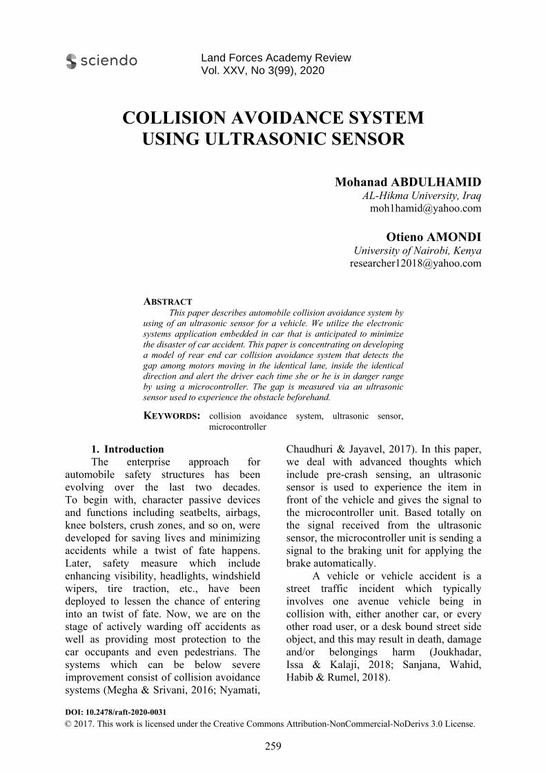
DOI: 10.2478/raft-2020-0031 COLLISION AVOIDANCE SYSTEM USING ULTRASONIC SENSOR Mohanad ABDULHAMID AL-Hikma University, Iraq [email protected] Otieno AMONDI University of Nairobi, Kenya [email protected] ABSTRACT This paper describes automobile collision avoidance system by using of an ultrasonic sensor for a vehicle. We utilize the electronic systems application embedded in car that is anticipated to minimize the disaster of car accident. This paper is concentrating on developing a model of rear end car collision avoidance system that detects the gap among motors moving in the identical lane, inside the identical direction and alert the driver each time she or he is in danger range by using a microcontroller. The gap is measured via an ultrasonic sensor used to experience the obstacle beforehand. KEYWORDS: collision avoidance system, ultrasonic sensor, microcontroller 1. Introduction The enterprise approach for automobile safety structures has been evolving over the last two decades. To begin with, character passive devices and functions including seatbelts, airbags, knee bolsters, crush zones, and so on, were developed for saving lives and minimizing accidents while a twist of fate happens. Later, safety measure which include enhancing visibility, headlights, windshield wipers, tire traction, etc., have been deployed to lessen the chance of entering into an twist of fate. Now, we are on the stage of actively warding off accidents as well as providing most protection to the car occupants and even pedestrians. The systems which can be below severe improvement consist of collision avoidance systems (Megha & Srivani, 2016; Nyamati, Chaudhuri & Jayavel, 2017). In this paper, we deal with advanced thoughts which include pre-crash sensing, an ultrasonic sensor is used to experience the item in front of the vehicle and gives the signal to the microcontroller unit. Based totally on the signal received from the ultrasonic sensor, the microcontroller unit is sending a signal to the braking unit for applying the brake automatically. A vehicle or vehicle accident is a street traffic incident which typically involves one avenue vehicle being in collision with, either another car, or every other road user, or a desk bound street side object, and this may result in death, damage and/or belongings harm (Joukhadar, Issa & Kalaji, 2018; Sanjana, Wahid, Habib & Rumel, 2018). © 2017. This work is licensed under the Creative Commons Attribution-NonCommercial-NoDerivs 3.0 License. 259 Land Forces Academy Review Vol. XXV, No 3(99), 2020
-
Upload
khangminh22 -
Category
Documents
-
view
4 -
download
0
Transcript of COLLISION AVOIDANCE SYSTEM USING ULTRASONIC ...
DOI: 10.2478/raft-2020-0031
COLLISION AVOIDANCE SYSTEM USING ULTRASONIC SENSOR
Mohanad ABDULHAMID AL-Hikma University, Iraq
Otieno AMONDI University of Nairobi, Kenya
ABSTRACT This paper describes automobile collision avoidance system by
using of an ultrasonic sensor for a vehicle. We utilize the electronic systems application embedded in car that is anticipated to minimize the disaster of car accident. This paper is concentrating on developing a model of rear end car collision avoidance system that detects the gap among motors moving in the identical lane, inside the identical direction and alert the driver each time she or he is in danger range by using a microcontroller. The gap is measured via an ultrasonic sensor used to experience the obstacle beforehand.
KEYWORDS: collision avoidance system, ultrasonic sensor, microcontroller
1. IntroductionThe enterprise approach for
automobile safety structures has been evolving over the last two decades. To begin with, character passive devices and functions including seatbelts, airbags, knee bolsters, crush zones, and so on, were developed for saving lives and minimizing accidents while a twist of fate happens. Later, safety measure which include enhancing visibility, headlights, windshield wipers, tire traction, etc., have been deployed to lessen the chance of entering into an twist of fate. Now, we are on the stage of actively warding off accidents as well as providing most protection to the car occupants and even pedestrians. The systems which can be below severe improvement consist of collision avoidance systems (Megha & Srivani, 2016; Nyamati,
Chaudhuri & Jayavel, 2017). In this paper, we deal with advanced thoughts which include pre-crash sensing, an ultrasonic sensor is used to experience the item in front of the vehicle and gives the signal to the microcontroller unit. Based totally on the signal received from the ultrasonic sensor, the microcontroller unit is sending a signal to the braking unit for applying the brake automatically.
A vehicle or vehicle accident is a street traffic incident which typically involves one avenue vehicle being in collision with, either another car, or every other road user, or a desk bound street side object, and this may result in death, damage and/or belongings harm (Joukhadar, Issa & Kalaji, 2018; Sanjana, Wahid, Habib & Rumel, 2018).
© 2017. This work is licensed under the Creative Commons Attribution-NonCommercial-NoDerivs 3.0 License.
259
Land Forces Academy Review Vol. XXV, No 3(99), 2020
Itmonetaras a rehandledresearchhassle (
Thalternatihassle bhome version present motive rather tprotectiproduceremedy lively sadvanceautomobmonths
2.Th
Atmegato receiunit andsend the
’s far a famry, physicalesult of card significanh must be cHang, Han,his study ive solutioby means oanti-collisithat wou
automobileforce in danthan puttingon gadget
ers, the perthe probl
safety gadged later tbile despiteof making
1. Central he micro
a 328P. Theive the echd the bit 1 e 10µs trigg
mous truth l and psychr accidents
ntly. Diversarried out t, Chen & Zh
is devoteon for thiof developiion warni
uld be inste fashions nger zone. Cg apart inbdevelopme
rson shall lem by gr
get model tto be fitte their versi. The scope
Figure
Control Moocontroller
e interrupt pho pulse fropin of regis
ger pulse.
that the sohological cris needs to se studies ao conquer thang, 2018)ed to stris recognizing low vaing machtalled on and alert
Consequentbuilt energeent to the find ways rowing hothat could ted to stron and twee of the pap
e no. 1: Blo(Source: M
odule used
pin one is usom the senster is used
cio isis be
and this ). rive zed
alue ine the the tly, etic car to
me be
reet lve per
enimsybeberesim
deanof Thpro
thamisyThthe
ck diagramMegha & Sri
is sed
nsor d to
whfal
beFigAt
ntails desimplementing
stem that efore it hits e written sponds in
mplemented
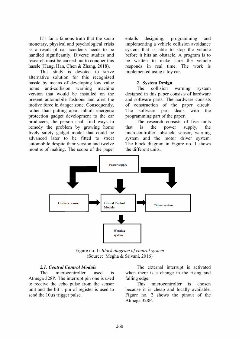
2. SysteThe
esigned in thnd software f constructhe softwaogramming
The resat is ticrocontrollstem and
he block die different u
of control sivani, 2016)
The exhen there illing edge.
This ecause it isgure no. 2tmega 328P
igning, pg a vehicle
is able toan obstaclto make
real timusing a toy
em Design collision his paper coparts. The
tion of thare part g part of the search conthe poweler, obstacl
the motoiagram in Funits.
system )
xternal inteis a change
microcontr cheap and2 shows t
P.
programmincollision av
o stop the le. A progra
sure the me. The wy car.
warning onsists of h
e hardware he paper deals wipaper.
nsists of fiver supplyle sensor, or driver Figure no.
errupt is ae in the ris
oller is d locally avthe pinout
ng and voidance
vehicle am is to
vehicle work is
system hardware
consists circuit.
ith the
ve units y, the warning system.
1 shows
activated sing and
chosen vailable.
of the
260
2.Th
followin 9 H D
2. Driver Che driver ng compone9v battery H-bridgeDC Motor
(Sou
Circuit circuit con
ents:
Figure no. 2urce: Joukh
nsists of
Figure n(Source: M
2: Atmega 3hadar, Issa &
the the0.0H-dioallsuin
no. 3: DriveMegha & Sri
328P pinou& Kalaji, 20
The DCe toy car08ms.The t-bridge becodes. The lowed for fficient to Figure no.
er system ivani, 2016)
t 018)
C Motor is r that dratip 122 is ucause it ha
maximumtip122 is
drive the m3 shows the
)
already incaws a curused to de
as its own m collector
5A. Thumotor. The e driver circ
cluded in rrent of sign the internal current
us, it is diagram
cuit.
261
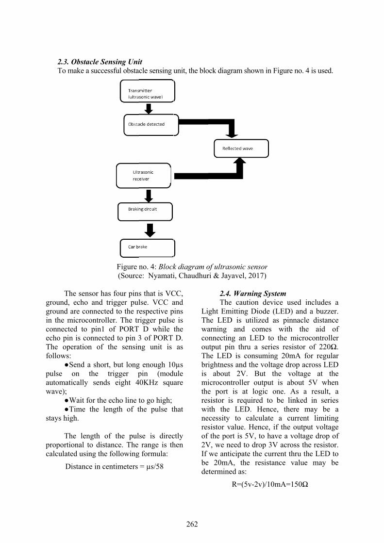
2.3. To m
Thground,ground in the mconnectecho pinThe opfollows
pulse automatwave);
W T
stays hi
Thproporticalculat
D
Obstacle Smake a succ
he sensor h echo and are connec
microcontroted to pin1n is connec
peration of : Send a shoon the
tically send
Wait for theTime the lgh.
he length ional to disted using th
Distance in c
Sensing Uniessful obsta
Figure (Sourc
has four pinstrigger pul
ted to the roller. The tr of PORT
cted to pin 3the sensin
rt, but longtrigger p
ds eight 4
e echo line tlength of t
of the pulstance. The e following
centimeters
it acle sensing u
no. 4: Blocke: Nyamati
s that is VClse. VCC a
respective prigger pulse D while 3 of PORT ng unit is
g enough 10pin (mod
40KHz squ
to go high; the pulse t
lse is direcrange is th
g formula:
= µs/58
unit, the blo
k diagram oi, Chaudhur
CC, and pins e is the D. as
0µs dule uare
that
ctly hen
LiThwacoouThbriis mithereswineresof 2VIf bede
ock diagram
of ultrasonicri & Jayavel
2.4. WaThe cau
ght Emittinhe LED is arning and
onnecting anutput pin thhe LED is ightness and
about 2Vicrocontrolle port is asistor is reith the LEecessity to sistor value
f the port is V, we need we anticipa
e 20mA, thetermined as
R=(
shown in Fi
c sensor l, 2017)
arning Systeution devic
ng Diode (Lutilized as
d comes n LED to thru a seriesconsumingd the voltag
V. But thler output at logic onquired to b
ED. Hence,calculate
e. Hence, if5V, to havto drop 3V
ate the currehe resistans:
(5v-2v)/10m
igure no. 4 i
em ce used incLED) and as pinnacle with the the microcos resistor o
g 20mA forge drop acrohe voltage is about 5Vne. As a rbe linked i, there maa current
f the outputve a voltage
V across the ent thru the
nce value
mA=150Ω
is used.
cludes a a buzzer. distance aid of
ontroller of 220Ω. r regular oss LED
at the V when result, a in series ay be a limiting
t voltage e drop of
resistor. e LED to may be
262
The buzzer is used for the low level distance warning. It is connected directly to the microcontroller output pin.
2.5. Software Design The software should be able to
acquire data from the sensor, analyze the data and send the data to the peripheral devices. The software should be integrated into the microcontroller. The language used to program the microcontroller is C++. The program is written in AVR Studio.
2.5.1. Programming Environment The programmer of choice is
AVRISPmkII. This programmer is easy to use and very effective. Figure no. 5 shows the AVRISPmkII. This is the programmer that is used to load the program file to the microcontroller. Figure no. 6 shows the pinout of AVRISPmkII. The AVRISPmkII pins are connected to the corresponding pins in the ATMEGA328P microcontroller.
Figure no. 5: AVRISP mkII programmer (Source: Nyamati, Chaudhuri & Jayavel, 2017)
Figure no. 6: AVRISPmkII pin out (Source: Megha & Srivani, 2016)
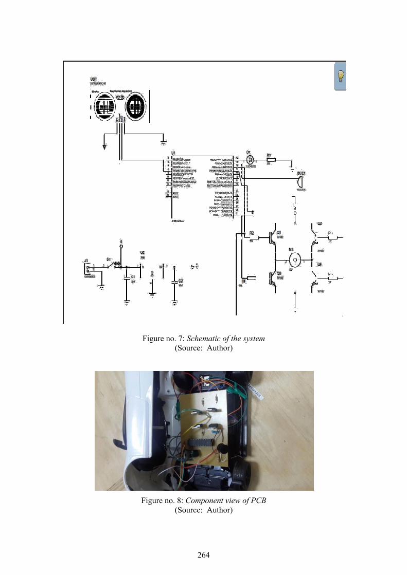
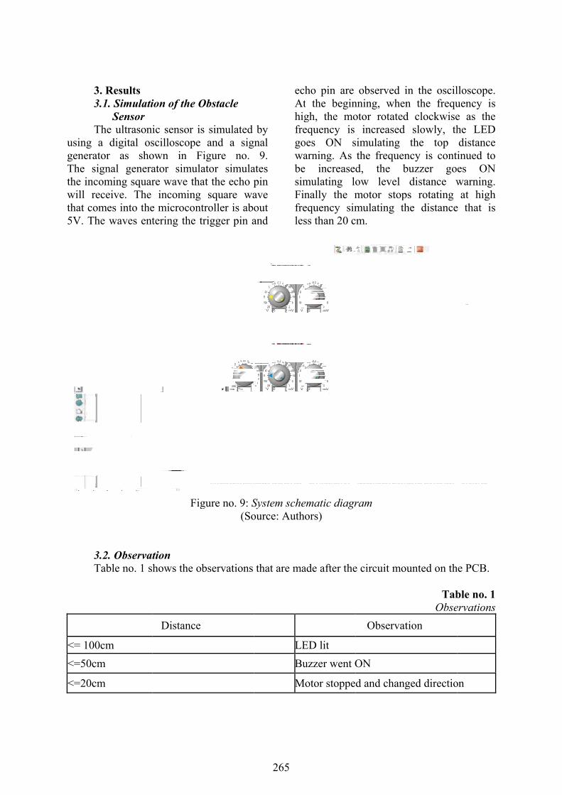
2.6. Final Design The schematic of the circuit in Figure
no. 7 is constructed on a breadboard and tested to meet the design specifications.
Once it is verified as working on the breadboard, a Printed Circuit Board (PCB) layout shown in Figure no. 8 is designed using PCB design software called Proteus.
263
F
Fi
igure no. 7:(So
igure no. 8: (So
: Schematic ource: Auth
Componenource: Auth
of the systehor)
t view of PChor)
em
CB
264
3.3.
Thusing ageneratoThe sigthe incowill recthat com5V. The
3.Ta
<= 100c
<=50cm
<=20cm
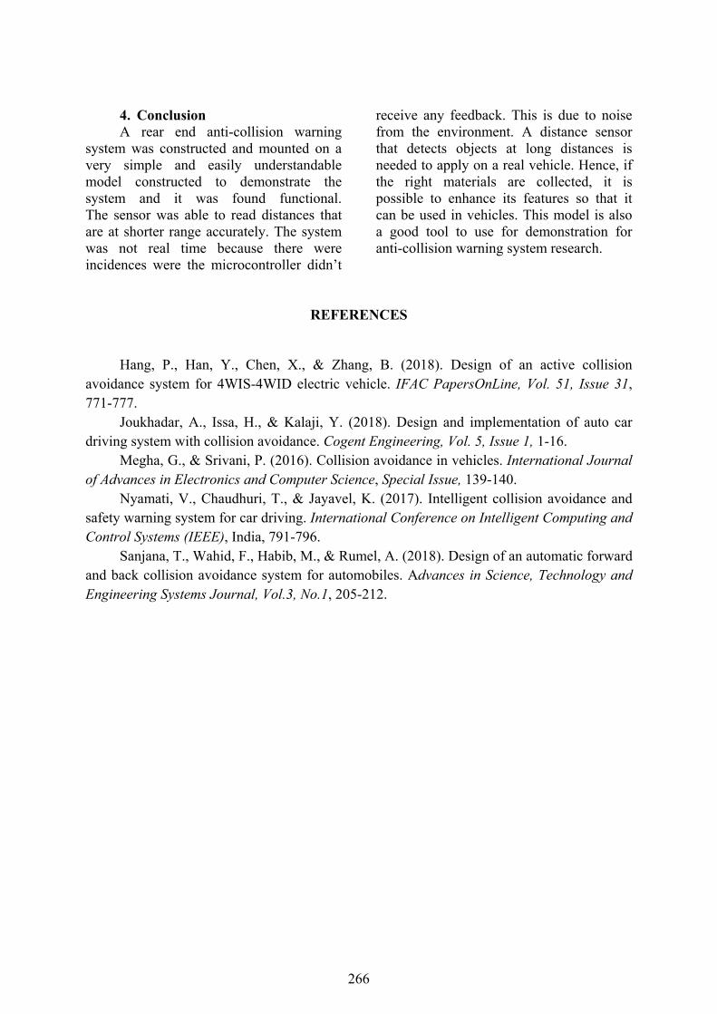
. Results 1. Simulati Sensor
he ultrasonia digital osor as shognal generaoming squarceive. The mes into thee waves ent
2. Observatable no. 1 s
cm
m
m
ion of the O
ic sensor isscilloscope own in Fiator simulare wave tha
incoming e microconttering the tr
Fig
tion hows the ob
Distance
Obstacle
s simulated and a sig
igure no. ator simulaat the echo p
square watroller is aborigger pin a
gure no. 9: S(So
bservations
by nal 9.
ates pin ave out and
ecAthigfregowabesimFinfreles
System scheource: Auth
that are ma
LE
Bu
M
ho pin are t the begingh, the moequency is oes ON sarning. As e increasedmulating lonally the mequency simss than 20 c
ematic diagrors)
ade after the
ED lit
uzzer went O
otor stoppe
observed inning, whenotor rotated
increased simulating the frequend, the bow level motor stopmulating th
cm.
ram
e circuit mo
Observat
ON
d and chang
in the osciln the frequd clockwise
slowly, ththe top
ncy is contbuzzer go
distance wps rotating he distance
unted on th
TabObse
tion
ged directio
lloscope. uency is e as the he LED distance inued to es ON warning. at high
e that is
he PCB.
ble no. 1 ervations
on
265
4. ConclusionA rear end anti-collision warning
system was constructed and mounted on a very simple and easily understandable model constructed to demonstrate the system and it was found functional. The sensor was able to read distances that are at shorter range accurately. The system was not real time because there were incidences were the microcontroller didn’t
receive any feedback. This is due to noise from the environment. A distance sensor that detects objects at long distances is needed to apply on a real vehicle. Hence, if the right materials are collected, it is possible to enhance its features so that it can be used in vehicles. This model is also a good tool to use for demonstration for anti-collision warning system research.
REFERENCES
Hang, P., Han, Y., Chen, X., & Zhang, B. (2018). Design of an active collision avoidance system for 4WIS-4WID electric vehicle. IFAC PapersOnLine, Vol. 51, Issue 31, 771-777.
Joukhadar, A., Issa, H., & Kalaji, Y. (2018). Design and implementation of auto cardriving system with collision avoidance. Cogent Engineering, Vol. 5, Issue 1, 1-16.
Megha, G., & Srivani, P. (2016). Collision avoidance in vehicles. International Journal of Advances in Electronics and Computer Science, Special Issue, 139-140.
Nyamati, V., Chaudhuri, T., & Jayavel, K. (2017). Intelligent collision avoidance and safety warning system for car driving. International Conference on Intelligent Computing and Control Systems (IEEE), India, 791-796.
Sanjana, T., Wahid, F., Habib, M., & Rumel, A. (2018). Design of an automatic forward and back collision avoidance system for automobiles. Advances in Science, Technology and Engineering Systems Journal, Vol.3, No.1, 205-212.
266