Car crash avoidance system using Ultrasonic Sensor
87
Sudan University of Science and Technology College of Graduate Studies Car crash avoidance system using Ultrasonic Sensor قجاث فس انو حساراث بإستخذانسيادو اظاو ينغ تصا نتيو انصA Thesis submitted in partial fulfillment of the requirements for the degree of M.Sc in Mechatronicscs Engineering By: Razan Mohammed Abbas Mohammed Ali Supervisor: Dr. Alaa Edeen Abdullah Awouda April.2017
-
Upload
khangminh22 -
Category
Documents
-
view
4 -
download
0
Transcript of Car crash avoidance system using Ultrasonic Sensor

Sudan University of Science and Technology College of Graduate Studies
Car crash avoidance system using Ultrasonic
Sensor
نظاو ينغ تصادو انسياراث بإستخذاو حساس انجاث فق انصتيو
A Thesis submitted in partial fulfillment of the requirements for the
degree of M.Sc in Mechatronicscs Engineering
By: Razan Mohammed Abbas Mohammed Ali
Supervisor:
Dr. Alaa Edeen Abdullah Awouda
April.2017

أليــةا
قال تعالي :نسان من عمق * اقرأ وربك الكرم * الذي عمم بالقمم * اقرأ باسم ربك الذي خمق ) * خمق ال
نسان ليطغى نسان ما لم يعمم * كل إن ال أن رآه استغنى * إن إلى ربك الرجعى * * عمم ال
نهى * عبدا إذا صمى * أرأيت إن كان عمى الهدى * أو أمر بالتقوى * أرأيت إن أرأيت الذي ي
ئة ة كاذبة خاط كذب وتولى * ألم يعمم بأن المو يرى * كل لئن لم ينتو لنسفعا بالناصية * ناصي
بانية * كل ل تطعو واسجد واقترب (* فميدع ناديو * سندع الز
صذق هللا انؼظيى
(11-1سره انؼهق االيو )

Dedication
For all people that I love them For every one stand behind me and encouraged me To produce this work

Acknoledgement
My gratitude and thanks to our god. I wish to
express my deepest gratitude to my supervisor DR.
AlaEldin Awouda for his conistant help, support and
guidance during this work.
Iam very thankful to Many people have helped
me through my way to keep this research project alive.
Finally, special thanks to my family for the
patience and cooperation during the preparation of
this work.

ABSTRACT
The main objective of this project is to develop a system in which it
counteracts a situation where the driver is travelling too close to another
vehicle or fixed object in front. However this project to develop a system
which will first realize the scenario and then act on it. The realizing part
can be achieved by installing ultrasonic sensor at the front of the vehicle.
This sensor will calculate distance of the gap between the vehicle and the
heading vehicle. The acting part of the system will be either slowing
down the vehicle or come to a complete stop.
Reportprocess to detect when the incident may help to save lives in
the event of medical help to arrive in a short time after knowing and
accurately identify the scene.

لصالمستخ
سزػو في انتحكى نظاو قادرػهي بناء ى انبحج ىذا ين انيذف انزئيس
االخزي. انسياره ين بينيا انسافو ػهي انسياره إػتادا
نسبو نتقهيم انتبهيغ انحادث يقغ ػن انكشف يتى حادث قع حانو في
طزيق ػن ,دقيق يتحكى بإستؼال ػهيا انذائزة ىذه تحقيق تى انفياث,
انارده نهؼهياث فقأ انحزك في سزػت انتحكى يتى يقانذق انتحكى بزيجت
انحساس انجاث فق انصتيت انذي يتى ضؼو في يقذيت انزكبت. ين

LISTOFCONTENTS
CHAPTERTITLEPAGE
II األية
DEDICATION III
ACKNOWLEDGMEMT IV
ABSTRACT V
VI المستخلص
LISTOF CONTENT VII
LISTOF TABLES IX
List of FIGURES X
ABBREVIATION XII
1INTRODUCTION 1
1.1 Over View 2
1.2 Objectives 3
1.3 Problem statements 3
1.4Problem Solution 4
1.5 Methodology 5
1.6 Chapter Organization 6
2 Litrarure Review and theoretical Background 7
2.1Literature Review 8
2.2 System Component 12
3 SYSTEMDESIGN 29
3.1 Project Overview 30

3.2 control system 30
3.3 circuit diagram and analysis 31
3.4 control system Flow charts and state Diagram 48
4 SIMULATIONANDRESULT 49
4.1 Read distance 50
4.3 Practical implemintation 58
5 CONCLUSIONS AND RECOMMENDATION 59
5.1 Conclusions 60
5.2 Recommendation 61
APPANDIXE „A‟ 64
APPANDIXE „B‟ 71
APPANDIXE „C‟ 76

LISTOFTABLES
NO TITLE PAGE
2.1 The difference between microprocessor and microcontroller14
2.2 ATMEGA 16 pins layout 17
2.3Connectivity of the LCD being use 35
3.1DIP 555 timer pin description 35
3.2 Pin Description 39
3.3 Pin of TX and RX 40
3.4 Pin Description 41
3.5Pins connections descriptions in ATMEGA 16 47
4.1Relationship between the number of pulses and the distance 51
4.2 Practical Implementation 58
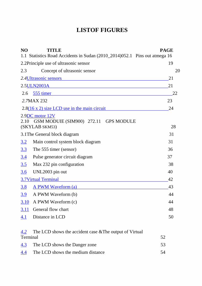
LISTOF FIGURES
NO TITLE PAGE 1.1 Statistics Road Accidents in Sudan (2010_2014)052.1 Pins out atmega 16
2.2Principle use of ultrasonic sensor 19
2.3 Concept of ultrasonic sensor 20
2.4Ultrasonic sensors 21
2.5ULN2003A 21
2.6 555 timer 22
2.7MAX 232 23
2.8(16 x 2) size LCD use in the main circuit 24
2.9DC motor 12V
2.10 GSM MODUIE (SIM900) 272.11 GPS MODULE
(SKYLAB SKM53) 28
3.1The General block diagram 31
3.2 Main control system block diagram 31
3.3 The 555 timer (sensor) 36
3.4 Pulse generator circuit diagram 37
3.5 Max 232 pin configuration 38
3.6 UNL2003 pin out 40
3.7Virtual Terminal 42
3.8 A PWM Waveform (a) 43
3.9 A PWM Waveform (b) 44
3.10 A PWM Waveform (c) 44
3.11 General flow chart 48
4.1 Distance in LCD 50
4.2 The LCD shows the accident case &The output of Virtual
Terminal 52
4.3 The LCD shows the Danger zone 53
4.4 The LCD shows the medium distance 54

4.5 The LCD shows the warning zone 55
4.6 The LCD shows the large distance 56
4.7The LCD show the safe zone 57
4.8Ultrasonic sensors in hardware 58
4.10 Hardware 58

LIST OFABBREVIATIONS
AVR Automation voltage regulator
ADC Analog to digital convertor
CPU Central Processing Unit
CISC Complex instruction set computer Com 1 Communications port 1
DC Direct Current
GSM Global System for Mobile GPS Global Positioning System
JTAG Joint Test Action Group LCD Liquid Crystal Display
LCU Logic control unit
LDR Light dependent resistor
LED Light Emitting Diode
MC Micro control unit
PWM Pulse width modulation
RISC Reduce instruction set computer
TTL Transistor–Transistor Logic

CHAPTER ONE
INTRODUCTION

1. INTRODUCTION
1.1 Over View:
Studies have shown that the rate of accidents in the world (65%), in Sudan by
(143%), and the expected increase in the year 2020's (193%) in the absence of the
development of the necessary measures and raise traffic awareness. [1].
The industry strategy for automotive safety systems has been evolving over
the last 20 years. Initially, individual passive devices and features such as seatbelts,
airbags, knee bolsters, crush zones, etc. was developed for saving lives and
minimizing injuries when an accident occurs. Later, preventive measures such as
improving visibility, headlights, windshield wipers, tire traction, etc. were deployed
to reduce the probability of getting into an accident. Now we are at the stage of
actively avoiding accidents as well as providing maximum protection to the vehicle
occupants and even pedestrians. Systems that are on the threshold of being
deployed or under intense development include collision avoidance systems. In this
dissertation, advanced ideas such as pre-crash sensing, ultrasonic sensor is used to
sense the object in front of the vehicle and gives the signal to the micro controller
unit. Based on the signal received from the ultrasonic sensor, the micro controller
unit sends a signal to the braking unit for applying the brake automatically as per
braking and throttle control logic fed in to the micro controller unit. To avoid the
collision between the vehicles during the period of running conditions and
automatically applying the brake by means of actuators, Distance measuring
sensors and Electronic control module and hence able to issue warnings to drivers
concerning any imminent dangers. As a consequence for the medium term, driver
assistance and communication systems will both be featured as integrated vehicle
modules to reduce traffic accidents significantly. The top model in our range, the
phaeton, is already available with the option of Automatic Distance Control (ADC),

which is geared to maintain automatically a minimum distance from the vehicle
ahead through system-initiated braking and acceleration. It isll known that driver
errors are the main cause for to increased severity, of most accidents. An increasing
amount of automotive systems, such as brakes, steering system and suspension, is
controllable by means of electronics and software. The expanded use of electronics,
micro controllers, sensors, actuators, etc. in the automotive industry will have a
major impact on the architecture of future safety systems.
1.2 Objectives:
1- To determine the distance between car with an object behind it.
2 - To inform the driver the state of car condition either they are in safe, warning or
stop zone through the colors of LED and display of LCD.
3- The vehicle should slow down until stop movement completely if the car in stop
zone.
4- An accident detection system which detects the accidents and by using GPS and
GSM we send the information of the location of the accident place to the police
station and relatives.
5- Simulate the proposal system and Performance evolution.
1.3 Problem statements:
Every year, hundreds case of road accident increase in our country, Sudan. the
number of the people died because of road accident is increasing year by year. The
table 1.1 shows us the statistic of an accident in Sudan from 2000 to2014. In
particular compiled by Sudan Police, these statistics show how many accidents
occur in Sudan.
One of the factors is the driver failure to control the vehicle in emergency
situation. The situation that the driver face is:
a) Emergency Stop.

b) Safety distance between vehicles,
c) High speed driving.
In case of accident ,Location cannot be detected Lack of an intelligent systems,
which use to detects accident, reported the concerned authorities.
Will be making model simulates the system to avoid the accident and reporting.
1.4 Problem Solution:
In this project the development of the system which will first realize the
scenario and then act on it. The realizing part can be achieved by installing sensors
at the front of the vehicle. These sensors will calculate distance of the gap between
the vehicle and the adjacent vehicle. In accident case, reported accidents by using
GSM and GPS to save the people. Performance evaluation of the design circuit will
be done during the solution for more accurate result.
Table 1.1: statistics of the accidents in Sudan from (2000 -2014).
Year
Death
Serious
Harm
Simple
Harm
Driving
Under
The
Influence
of
Alcohols
Driving
Negligently
Traffic
violations
Total
Percentage

Figure 1.1: Statistics Road Accidents in Sudan (2010_2014)
Source: Khartoum State Traffic Police.
1.5 Methodology:
There are two main scopes in this project which is software development and
hardware development. This project scope is limited to design an automotive
system that consists of distance measurement and controlling the velocity of the
vehicle. The realizing part can be achieved by installing sensors at the front of the
vehicle. These sensors will calculate distance of the gap between the vehicle and the
adjacent vehicle the acting part of the system will be divided into two categories.
The first category is when the distance of the gap between the vehicle and a fixed
object is close and the driver is still driving at a high speed. The system will
counteract in this situation by momentarily taking over the driving system and
2010 891 3695 6156 260 33752 524852 569606 %18.9
2011 821 3663 4665 270 33017 396160 438596 %14.5
2012 768 3058 4651 245 32902 527824 569448 %18.9
2013 677 3010 4605 253 32213 545962 586720 %19.5
2014 709 2904 4351 198 31970 812013 852145 %28.2
Total 3966 16330 24428 1226 133854 2806811 3016515 %100

applying the brakes to lower the speed to widen the gap between the car and the
object or come to a complete stop if the car in critical state .
The second besides this facility, in accident case we also provide an accident
detection system which detects the accidents, and send the information of the
location of the accident place to the police station and relatives by using GPS and
GSM, which is most useful information to save the people.
1.6 Chapter Organization:
CHAPTER ONE: proposed introduction for project also objective. CHAPTER
TWO: show the Related Works and basic component.
CHAPTER THREE: discuss system design and description of all sensors and
control of motor, select location by GPS and send report by GSM. CHAPTER
FOUR: show the result of simulation work and many scenarios. CHAPTER FIVE:
proposed conclusion and recommendations.

CHPATER TWO
LITRARURE REVIEW AND THEORETICAL
BACKGROUND

2. Literature Review
2.1 Literature Review and Related Works Covered:
Automatic vehicle over speed, accident alert and locator system for
public transport (Buses).
In paper use system to monitor the speed and accident use GSM and GPS
.and developed SMS application by use Microsoft visual studio package Microsoft
SQL saver was used for storing data and used specializes web the administrator the
control data base serves was able to extract. GPS receiver with active antenna
.GSM modems SIM900D PIC18F4520 microcontroller, mobile phone handset
Nokia 110 and laptop computer.
On Board Processing Unit (OBPS)
Control Database Server (CDS)
Mobile Phone Handsets[2]
A Design & Implementation of Collision Avoidance System (CAS) for
Automobiles using Embedded System.
In paper use advance ideas such as pre-crash sensing, ultrasonic sensor is
used to sense the object in front of Based on the signal received from the ultrasonic
sensor the micro controller unit sends a signal to the braking unit for applying the
brake automatically as per[3]
Car Authentication and Accident Intimation System Using GPS and
GSM.
in paper use There are three main modules when an accident happen GPS
co-ordinates of the location are messaged to the nearby hospitals a text message is
sent to the owner thereby intimating the status of the car The serial communication
interface UART is used for the communication between the Microcontroller (PIC
16F877A), GSM and GPS module. The RS232 communication standard is used for
the following purposes.[4]
Automatic Vehicle Accident Detection System Based on ARM &GPS.
in paper use an MEMS sensor, GPS & GSM The system detects the vehicle
accident with the help of vibration sensor or MEMS sensor case reason like having
heart attack problem at that time a message is transmitted to the medical help center
by just pressing a single switch.[5]
Accident messaging system.
In paper use accident technique occurs MEMS sensor detect and sends
electrical signal to the ADC channel of the PIC microcontroller By using GPS , we
get particular location where accident occurs, then GSM modem sends message to
authorized mobile number[6]
CAN BASED COLLISION AVOIDANCE SYSTEM FOR
AUTOMOBILES.
In paper having two nodes each node Contain ATMEGA 16 and
MCP2515 In first node we are interfacing GP2D12 to find the object, second node
contains DC motor initially motor is rotating with maximum speed. If any object is
found in front of GP2D12 in node1 motor will stop in node2 by using CAN
protocol. For this we have to develop two different application programs in
embedded .[7]
Autonomous Remote Control Car with Lane Detection and Collision
Avoidance System.
In paper using RFID If the wrong goods are taken out of the vehicle, the
buzzer gets activated. The obstacle detection can be done by ultrasonic sensors. If
any obstacle in the route is detected, the message is sent to the control station of the
industry using the GSM module and use LCD to display commonly used in Various
devices and circuits [8]

Advanced Accident Avoidance System for Automobiles.
In paper used to system
1. Collision Avoidance System (CAS)
2. Automated Accident Detection and
3. Information system (AADIS).[9]
Automatic Vehicle Accident Detection and Messaging System Using
GPS and GSM Modems.
The aim of our work is to find the vehicle accident location by means of
sending a message using a system which is placed inside of vehicle system. use
microcontroller AT89C52 GSM and GPS and used 9.pin "AT STYLE [10]
Development and Testing of a Vehicle Collision Avoidance System
Based on GPS and Wireless Networks for Open-Pit Mines.
in paper use 3D graphics technology to reduce powered haulage equipment
accidence in open pit mining operations and testing results of GPS accuracy Level
achieved are presented[11]
Automatic Accident Alert and Safety System using Embedded GSM
Interface.
The system envisioned is an automatic collision detection and warning
system relying on GPS module and a GSM modem. The vehicle to be safeguarded
is to be fitted with the system sturdily ensuring good mechanical coupling with the
entire chassis. In the case of an accident the system detects it using the fact that the
vehicle would be suddenly decelerated in such a condition. An accelerometer
continuously monitors the acceleration of the vehicle and will detect decelerations
greater than threshold value and send the data to the microcontroller via an ADC.
The controller compares this with the threshold set value and immediately sends an
SOS message to preset numbers. With this message the controller also transmits the

GPS coordinates of the vehicle which it continuously obtains from the GPS module.
[12]
SMART CAR SYSTEM USING SENSOR, GPS AND GSM.
To improve overall system, Microcontroller featured with GSM and GPS
interface. GPS device received valid GPS signals from satellite and send calculated
longitude and latitude and speed of the vehicle to microcontroller at every one
second. Microcontroller continuously monitor the speed received from GPS if there
is a huge predefined difference between two consecutive readings of speed from the
GPS[13]
Accident Prevention and Reporting System Using GSM (SIM 900D) and
GPS (NMEA 0183).
Our system consists of two parts, alarming part and messaging part. The
hardware includes SONAR ranging modules, vibration sensor, three modules GPS
receiver (NMEA), Microcontroller (AT89S51), GSM modem (SIM 900D) and an
Alarm. When distance is too short between the vehicle and obstacle then alarm will
be “ON” as an indicator to move vehicle in other direction which is safer but when
a vehicle faces accident despite of alarm, immediately vibration sensor will detect
the signal and then Microcontroller sends the alert message through the GSM
modem including the location to predefined numbers that can be reserved for a
rescue team. Our designed system[14]
Intelligent accident identification system using GPS, GSM modem.
The concept of this scheme is to green the traffic signal in the path of
ambulance automatically with the help of RF module. So that the ambulance can
reach the spot in time and human life can be saved and the accident location is
identified sends the accident location immediately to the main server. The main
server finds the nearest ambulance to the accident zone and sends the exact accident
location to the emergency vehicle. The control unit monitors the ambulance and

provides the shortest path to the ambulance at the same time it controls the traffic
light according to the ambulance location and thus arriving at the hospital[15]
Vehicle Accident Detection and Reporting System Using GPS and
GSM.
Accelerometer sensor can be used in car security system to sense vibrations
in vehicle and GPS to give location of vehicle, so dangerous driving can be
detected. When accident occurs, Accelerometer will detect signal and will send
signal to AVR controller, microcontroller will enable airbag to blow and message
with accident location is sent to preprogrammed numbers such as ambulance, police
station, etc. via GSM.[16]
2.2 System Component:
This section will discuss about components that had been used included
Ultrasonic sensor (HC-SR04), power supply 9V, microcontroller ATMEGA 16, DC
Motor, and Liquid crystal display (LCD) Global Positioning System (GPS). Global
System for Mobile (GSM)
Microprocessor:
A microprocessor uses microelectronic fabrication techniques to shrink the
CPU to a very small size; usually a single "chip."
Microcontrollers:
“Microcontrollers”. Micro because they‟re small and controller because they
“control” machines, gadgets, whatever, Microcontroller‟s by definition then, are
designed to connect to machines, rather than people.

A microcontroller is a small, low-cost computer-on-a-chip which usually
includes:-
1- An 8 or 16 bit microprocessor (CPU).
2- A small amount of RAM.
3- Programmable ROM and/or flash memory.
4- Parallel and/or serial I/O.
5- Timers and signal generators.
6- Analog to Digital (A/D) and/or Digital to Analog (D/A) conversion.
Often it used to run dedicated code that controls one or more tasks in the
operation of a device or a system. Also called embedded controllers, because the
microcontroller and support circuits are often built into, or embedded in, the devices
they control. Devices that utilize microcontrollers include car engines, consumer
electronics (VCRs), microwaves, cameras, pagers, cell phones computer peripherals
(keyboards, printers, modems), test/measurement equipment (signal generators,
millimeters, oscilloscopes Microcontrollers usually must have low-power
requirements (05 - 1 W) as opposed to ~10 - 50 W for general purpose desktop
CPUs) since many devices they control are battery-operated.
Table: 2.1:The difference between microprocessor and microcontroller.
MICROPROCESSOR MICROCONTROLLER
A microprocessor is a chip that
dependent on the chip of many
functions.
A microcontroller is a single chip
micro-computer that has everything
in –built.
A microprocessor contains ALU
register and control circuit.
A contains the circuitry of a
microcontroller and has built in
RAM, ROM I/O devices, timers and
counter.
It has few bit manipulation
instruction.
It has many bit manipulation
instruction.
it has less number of
multifunctional pins.
It has more number of
multifunctional pins.

They have large memory address
space.
They have small memory address
space.
Design is very flexible. Design is less flexible.
A microprocessor based system
required more hardware.
Microcontroller based system
required less hardware.
Access time for memory and I/O Less access time for built-in memory.
AVR Microcontroller:
AVR also known as Advanced Virtual RISC, is a customized Harvard
architecture 8 bit RISC solitary chip micro-controller. It was invented in the year
1966 by Atmel. Harvard architecture signifies that program & data are amassed in
different spaces and are used simultaneously. It was one of the foremost micro-
controller families to employ on-chip flash memory basically for storing program,
as contrasting to one time programmable EPROM, EEPROM or ROM, utilized by
other micro-controllers at the same time. Flash memory is a non-volatile (constant
on power down) programmable memory.
2.2.1 ATmega16:
The ATmega16 is a low-power CMOS 8-bit microcontroller based on the
AVR enhanced RISC architecture. By executing powerful instructions in a single
clock cycle, the ATmega16 achieves throughputs approaching 1 MIPS per MHz
allowing the system designed to optimize power consumption versus processing
speed.
Features:
1- High-performance , Low-power
2- Advanced RISC Architecture
3- High Endurance Non-volatile Memory segments
4- JTAG (IEEE std. 1149.1 Compliant) Interface
– Real Time Counter with Separate Oscillator
– Four PWM Channels

– 8-channel, 10-bit ADC
5- Special Microcontroller Features
– Power-on Reset and Programmable Brown-out Detection.
– Internal Calibrated RC Oscillator
– External and Internal Interrupt Sources
– Six Sleep Modes: Idle, ADC Noise Reduction, Power-save.
6- I/O and Packages
– 32 Programmable I/O Lines
– 40-pin PDIP, 44-lead TQFP, and 44-pad QFN/MLF
7- Operating Voltages
– 2.7V - 5.5V for ATmega16L
– 4.5V - 5.5V for ATmega16
8- Speed Grades
– 0 - 8 MHz for ATmega16L
– 0 - 16 MHz for ATmega16
Figure: 2.2 Pins out ATMEGA 16.
.

Table: 2.2 ATMEGA 16 pins layout.
VCC DIGITAL SUPPLY VOLTAGE
GND Ground.
Port A Port A serves as the analog inputs to the A/D
Converter. Port A also serves as an 8-bit bi-
directional I/O port
Port B Port B is an 8-bit bi-directional I/O port with
internal pull-up resistors (selected for each bit).
Port C Port C is an 8-bit bi-directional I/O port with
internal pull-up resistors (selected for each bit).
Port D Port D is an 8-bit bi-directional I/O port with
internal pull-up resistors (selected for each bit).
RESET Reset Input. A low level on this pin for longer than
the minimum pulse length will generate a reset,
even if the clock is not running.
XTAL1 Input to the inverting Oscillator amplifier and input
to the internal clock operating circuit.
XTAL2 Output from the inverting Oscillator amplifier.
AVCC AVCC is the supply voltage pin for Port A
and the A/D Converter. It should be externally
connected to VCC, even if the ADC is not used. If
the ADC is used, it should be connected to VCC
through a low-pass filter.
AREF AREF is the analog reference pin for the A/D
Converter.

2.2.2 Ultrasonic sensor:
Ultrasonic transducers are transducers that convert ultrasound waves to
electrical signals or vice versa. Those that both transmit and receive may also be
called ultrasound transceivers; many ultrasound sensors besides being sensors are
indeed transceivers because they can both sense and transmit. These devices work
on a principle similar to that of transducers used in radar and sonar systems, which
evaluate attributes of a target by interpreting the echoes from radio or sound waves,
respectively. Active ultrasonic sensors generate high frequency sound waves and
evaluate the echo which is received back by the sensor, measuring the time interval
between sending the signal and receiving the echo to determine the distance to an
object. Passive ultrasonic sensors are basically microphones that detect ultrasonic
noise that is present under certain conditions, convert it to an electrical signal, and
report it to a computer.
Measurement Principle :
Ultrasonic sensors transmit ultrasonic waves from its sensor head and again
receive the ultrasonic waves reflected from an object. By measuring the length of
time from the transmission to reception of the sonic wave, it detects the position of
the object.

Figure: 2.3 Principle use of ultrasonic sensor.
The advantages of Ultrasonic sensor.
1-Measures and detects distances of moving objects.
2- Impervious to target materials, surface and color.
3- Solid-state units have virtually unlimited, maintenance-free lifespan.
4- Detects small objects over long operating distances.
5- Resistant to external disturbances such as vibration, infrared radiation,
ambient noise and EMI radiation.
6- Ultrasonic sensors are not affected by dust, dirt or high-moisture
environments.

7- Ultrasonic sensors are not affected by dust, dirt or high-moisture
environments.
8-Discrete distances to moving objects can be detected and measured.
The disadvantages of Ultrasonic sensor:
1- Overheating of a wave emitter precludes the energy of ultrasonic waves
emitted there from being enhanced to a practical level.
2- Interference between the projected waves and the reflected waves takes
place, and development of standing waves provides adverse effects.
3- It is impossible to discern between reflected waves from the road surface
and reflected waves from other places or objects.
4- There is no effective measure for removing the influences of factors other
than road surface irregularities for example, winds, temperature variations,
etc., which can change the intensity of reflected waves.
Figure: 2.4 Concept of ultrasonic sensor.
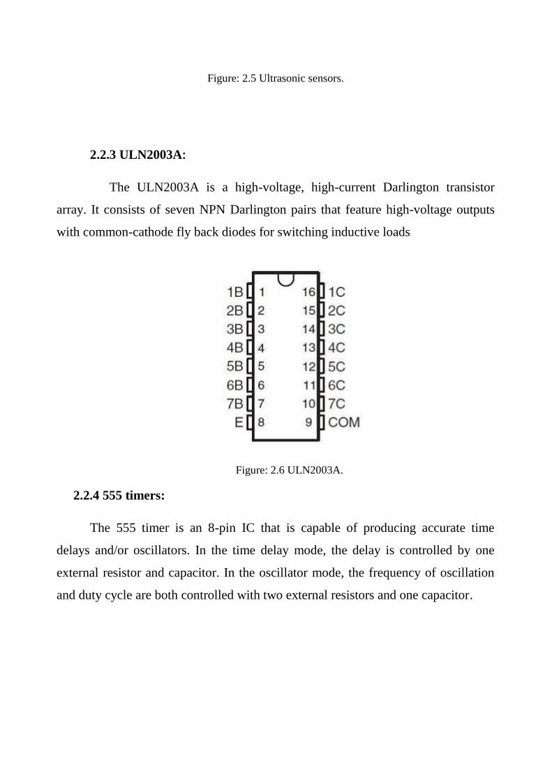
Figure: 2.5 Ultrasonic sensors.
2.2.3 ULN2003A:
The ULN2003A is a high-voltage, high-current Darlington transistor
array. It consists of seven NPN Darlington pairs that feature high-voltage outputs
with common-cathode fly back diodes for switching inductive loads
Figure: 2.6 ULN2003A.
2.2.4 555 timers:
The 555 timer is an 8-pin IC that is capable of producing accurate time
delays and/or oscillators. In the time delay mode, the delay is controlled by one
external resistor and capacitor. In the oscillator mode, the frequency of oscillation
and duty cycle are both controlled with two external resistors and one capacitor.

Figure: 2.7 555 timer.
2.2.5 MAX232
The MAX232 is a hardware layer protocol converter IC manufactured by the
Maxim Corporation. Commonly known as a RS-232 Transceiver, it consists of a
pair of drivers and a pair of receivers. At a very basic level, the driver converts TTL
and CMOS voltage levels to TIA/EIA-232-E levels, which are compatible for serial
port communications. The receiver performs the reverse conversion.
Used in embedded microcontroller systems, and computers, this IC has been
one of the most popular components in production for well over two decades. If you
have a microcontroller circuit that requires communication through a serial port,
then this is the chip to use. This is a versatile IC, which is one of those wonderful
components that solve so many signal conversion problems.

Figure: 2.8 MAX 232.
2.2.6 LCD (liquid crystal display)
The technology used for displays in notebook and other smaller computers.
Like light-emitting diode (LED) and gas-plasma technologies, LCDs allow displays
to be much thinner than cathode ray tube (CRT) technology. LCDs consume much
less power than LED and gas-display displays because they work on the principle
of blocking light rather than emitting it. An LCD is made with either a passive
matrix or an active matrix display grid. The active matrix LCD is also known as a
thin film transistor (TFT) display. The passive matrix LCD has a grid of conductors
with pixels located at each intersection in the grid. A current is sent across two
conductors on the grid to control the light for any pixel. An active matrix has a
transistor located at each pixel intersection, requiring less current to control the
luminance of a pixel. For this reason, the current in an active matrix display can be
switched on and off more frequently, improving the screen refresh time (your
mouse will appear to move more smoothly across the screen, for example). Active
matrix is the superior technology.

The 16x2 size of LCD is use in the main microcontroller circuit to display the
status of the main circuit function. Resistor value between 1Kohm to 10Kohm is
use for the brightness of the LCD and the 10 ohm resistor with respective to the
ground is use to light up the back light of the LCD.
Figure 2.9: (16 x 2) size LCD use in the main circuit.
Table2.3: Connectivity of the LCD being use.
PIN NAME PIN FUNCTION CONNECTION
1 VSS Ground GND

2 Vdd Positive supply
for LCD
5V
3 VO Brightness adjust Connected to a preset
to adjust brightness
4 RS Select register,
select instruction or data
register
PIN PIC
5 R/W Select read or
write
GND
6 E Start data read or
write
PIN PIC
7 DB0 To DB7 Data bus pin PIN PIC
8 LED+ Backlight positive
input
VCC
9 LED- Backlight
negative input
GND
2.2.7 DC motor:
DC motor used in this project is the small car (toy car) with a capacity of 12
volt.

Figure 2.10: DC motor 12V.
2.2.8 GSM MODUIE (SIM900):
GPRS module is a breakout board and minimum system of SIM900 Quad-
band/SIM900A Dual-band GSM/GPRS module. It can communicate with
controllers via AT commands (GSM 07.07, 07.05 and SIMCOM enhanced AT
Commands). This module supports software power on and reset. IO List: GND ,
+5V , RX , TX , PWR , RST.
Booting the GSM Module:
1. Insert the SIM card to GSM module and lock it.
2. Connect the adapter to GSM module and turn it ON.
3. Now wait for some time (say 1 minute) and see the blinking rate of „status LED‟
or „network LED‟ (GSM module will take some time to establish connection with
mobile network).
4. Once the connection is established successfully, the status/network LED will
blink continuously every 3 seconds. You may try making a call to the mobile
number of the SIM card inside GSM module. If you hear a ring back, the GSM
module has successfully established network connection.
Features
1- Quad-Band 850/ 900/ 1800/ 1900 MHz

2- Dual-Band 900/ 1900 MHz
3- GPRS multi-slot class 10/8GPRS mobile station class B
4- Compliant to GSM phase 2/2+Class 4 (2 W @850/ 900 MHz)
5- Class 1 (1 W @ 1800/1900MHz)
6- Control via AT commands (GSM 07.07 ,07.05 and SIMCOM
enhanced AT Commands)
7- Low power consumption: 1.5mA(sleep mode)
8- Operation temperature: -40°C to +85 °C
Figure 2.11: GSM MODUIE (SIM900).
2.2.9 GPS MODEM (SKYLAB SKM53):
GPS modem is a device which receives signals from satellite and provides
information about latitude, longitude, altitude, time etc. The GPS navigator is more
famous in mobiles to track the road maps. The GPS modem has an antenna which
receives the satellite signals and transfers them to the modem. The modem in turn
converts the data into useful information and sends the output in serial RS232 logic
level format. The information about latitude, longitude etc is sent continuously and
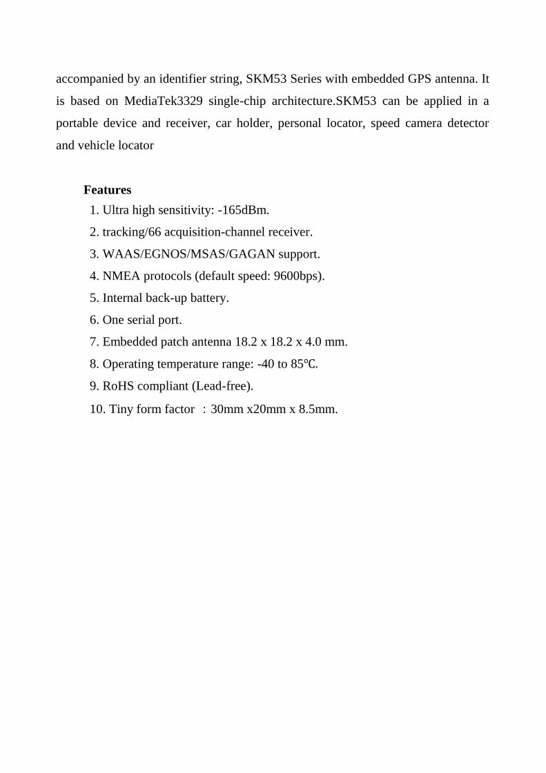
accompanied by an identifier string, SKM53 Series with embedded GPS antenna. It
is based on MediaTek3329 single-chip architecture.SKM53 can be applied in a
portable device and receiver, car holder, personal locator, speed camera detector
and vehicle locator
Features
1. Ultra high sensitivity: -165dBm.
2. tracking/66 acquisition-channel receiver.
3. WAAS/EGNOS/MSAS/GAGAN support.
4. NMEA protocols (default speed: 9600bps).
5. Internal back-up battery.
6. One serial port.
7. Embedded patch antenna 18.2 x 18.2 x 4.0 mm.
8. Operating temperature range: -40 to 85℃.
9. RoHS compliant (Lead-free).
10. Tiny form factor :30mm x20mm x 8.5mm.

Figure 2.12: GPS MODULE (SKYLAB SKM53).

CHPATER THREE
SYSTEM DESIGN

3. SYSTEM DESIGN
3.1 Project Overview
The main aim of thesis work is implementation of the Car crash avoidance
system using ATMEGA16 Microcontroller. To implement this prototype car
avoidance system is considered which consists of D.C motors , ultrasonic sensor ,
and display module.
Besides this facility the system provides an accident detection which detects
the accidents and by using GPS and GSM we send the information of the location
of the accident place to the police station and relatives. This is most useful
information to save the persons.
3.2 control system
This project is mainly focus on DC motor speed and distance control system
by using microcontroller. The actual distance has been measured using ultrasonic
sensor and feedback to microcontroller. Microcontroller has been used as the
controller to control DC motor speed and desired spacing between both vehicles.
The controller will determine duty cycle of pulse-width-modulation (PWM) in
microcontroller. Based on the data of distance calculation. AVR Microcontroller
produces the intelligent control setting by giving a 5V high bit of control signal to
one of six condition lines. These six of control conditions include: speed up, speed
down, speed remain, brake/stop, Determine the location and send the location.
The basic structure diagram of system positioning control system model is
show in figure 3.1. The system includes ATMEGA16, DC motor (driver module),
ultrasonic sensor, LCD display module, GSM, GPS.

Figure: 3.1 The General block diagram.
3.3 circuit diagram and analysis:
In the following section, the system will be described in details:
Figure 3.2: Main control system block diagram.
1. Ultrasonic sensor: The microcontroller sends TRIG and Ultrasonic sensor
feedback is ECHO signal back to microcontroller. the microcontroller
Calculated the Distance by use feedback of Ultrasonic sensor
Ultrasonic
sensor
Microcontroller
AVR
LCD
MAX
232
ULN
2003A
GSM &
GPS
D.C motor

2. Max 232: to convert signal voltage levels signal to (up to convert) or from
(down convert) GSM &GPS need to convert or modulation amplitude.
3. ULN 2003A: to drives a motor to Acceleration or Slow or stop the speed
of motor, that use supply voltages of 6 V to 15 V.
4. Microcontroller: to control the motor .
5. And GSM & GPS and read from sensor.
6. LCD : to display all of the activities that the microcontroller is working on
(distance and Location )
7. Motor: dc motor to drive car.
The microcontroller send trig to sensor., after which time the "Echo"
send the signal to microcontroller, and microcontroller measure a distance using
calculations . Based on the distance the microcontroller take action if the distance
between car and object , If the distance far large no action just motor going highest
speed, display the distance and the location, if the distance in middle the
microcontroller send signal to drives motor to Slow the speed, if a distance is close
the microcontroller send signal to stop motor , when the collision car Collision cars
Collision cars send to max 232 To activate the GPS to select the location and after
send the location of collision to The selected number is often the relatives or the
police center.
3.3.1 Ultrasonic sensor:
Is a popular and low cost solution for non-contact distance measurement
function. It is able to measure distances from 2cm to 400cm with an accuracy of
about 3mm. This module includes ultrasonic transmitter, ultrasonic receiver and its
control circuit, Module has 4 pins
1. VCC – 5V, of the power supply
2. TRIG – Trigger Pin
3. ECHO – Echo Pin
4. GND – - the power supply

TRIG and ECHO pins can be used to interface this module with a
microcontroller unit. These are TTL (0 – 5V) input output pins.
Steps that must be followed to work the sensor :
1. Microcontroller send trig to "Trig" pin of the sensor high for 10µs. This
initiates a sensor cycle.
2. The sensor Generates 8 pulses everyone 40KHz, 8 x 40 kHz pulses will
be sent from the transmitting piazza transducer of the sensor, after which
time the "Echo" pin on the sensor will go from low to high.
3. The 40 kHz sound wave will bounce off the nearest object and return to
the sensor.
4. When the sensor detects the reflected sound wave, the Echo pin will go
low again.
5. The distance between the sensor and the detected object can be calculated
based on the length of time the Echo pin is high.
If no object is detected, the Echo pin will stay high for 38ms and then go
low.
accord to Not available ultrasonic sensor in simulation program (Proteus) It
has been replaced 555 timer Circuit in Projects Theory of work are the same but
with the existence of differences The production Series of pulses Via 555 timer the
pulses insert to microcontroller Similarity of output of sensor.
ITS:
1. Working Voltage : 5V(DC)
2. Working Current : 15mA
3. Working frequency : 40HZ
4. Output: 0-5V (Output high when obstacle detected in range)
5. Beam Angle: Max 15 degree.
6. Distance: 2cm - 400cm.
7. Accuracy: 0.3cm.

8. Input trigger signal : 10us impulse TTL
9. Echo signal: PWM signal (time required for sound signal to travel twice
between source and obstacle).
10. Size: 45mm*20mm*15 mm.
3.3.2 555 timer:
The 555 timer is an extremely versatile integrated circuit which can be used
to build lots of different circuits. You can use the 555 effectively without
understanding the function of each pin in detail.
Frequently, the 555 is used in actable mode to generate a continuous series of
pulses.
Table 3.1: DIP 555 timer pin description.

Table 3.1: DIP 555 timer pin description.
Figure:
3.3 The
555
timer
(sensor
).
T
his is
a
pulse
generator with adjustable duty cycle made with the 555 timer IC. The circuit is an
PIN NAME PURPOSE
1 GND Ground reference voltage, low level (0 V)
2 TRIG The OUT pin goes high and a timing interval starts when
this input falls below 1/2 of CTRL voltage (which is
typically 1/3 VCC, CTRL being 2/3 VCC by default if
CTRL is left open).
3 OUT This output is driven to approximately 1.7 V below +VCC,
or to GND.
4 RESET A timing interval may be reset by driving this input to
GND, but the timing does not begin again until RESET
rises above approximately 0.7 volts. Overrides TRIG
which overrides THR.
5 CTRL Provides "control" access to the internal voltage divider
(by default, 2/3 VCC).
6 THR The timing (OUT high) interval ends when the voltage at
THR ("threshold") is greater than that at CTRL (2/3 VCC if
CTRL is open).
7 DIS Open collector output which may discharge a capacitor
between intervals. In phase with output.
8 VCC Positive supply voltage, which is usually between 3 and
15 V depending on the variation.

astable multivibrator with a 50% pulse duty cycle. The difference from the standard
design of a 555 timer is the resistance between pins 6 and 7 of the IC composed of
P1, P2, R2, D1 and D2.
The diodes D1 and D2 set a definite charging time for C1 which produces a
50% duty cycle in a normal case. The duty cycle (n) is dependent on P1 and P2 in
the following manner:
n = 1 + P2/P1
If P2 = 0 (n = 100%) then the frequency can be approximately calculated
with the following formula:
f = 0.69/((2*P1 + P2 + 4.7kΩ)*C1)
Figure: 3.4 Pulse generator circuit diagram.

3.3.3 Max 232:
This module is primary of interest for people building their own electronics
with an RS-232 interface. Off-the-shelf computers with RS-232 interfaces already
contain the necessary electronics, and there is no need to add the circuitry (Max
232) max232 to convert signal from TTL level
(microcontroller) to RS232 level (PC ,COM) the microcontroller use binary 0
, 1 levels volt for 0 logic and 5+ volt to 1 logic but the RS 232 ( PC,COM) was
defined at a different level - for logic 0 it ranges from +3v to +15 v and for logic 1
its -3v to -15v.
Figure: 3.5 Max 232 pin configuration.

Features
1. Meets or Exceeds TIA/EIA-232-F and ITU Recommendation V.28
2. Operates From a Single 5-V Power Supply With 1.0-μF Charge-Pump
Capacitors
3. Operates up to 120 Kbit/s
4. Two Drivers and Two Receivers
5. ±30-V Input Levels
6. Low Supply Current: 8 mA Typical.

Table 3.2: Pin Description.
PIN
NO
FUNCTION NAME
1 Capacitor connection pins Capacitor 1 +
2 Capacitor 3 +
3 Capacitor 1 -
4 Capacitor 2 +
5 Capacitor 2 -
6 Capacitor 4 -
7 Output pin; outputs the serially transmitted data at RS232
logic level; connected to receiver pin of PC serial port
T2 Out
8 Input pin; receives serially transmitted data at RS 232
logic level; connected to transmitter pin of PC serial port
R2 In
9 Output pin; outputs the serially transmitted data at TTL
logic level; connected to receiver pin of controller.
R2 Out
10 Input pins; receive the serial data at TTL logic level;
connected to serial transmitter pin of controller.
T2 In
11 T1 In
12 Output pin; outputs the serially transmitted data at TTL
logic level; connected to receiver pin of controller.
R1 Out
13 Input pin; receives serially transmitted data at RS 232
logic level; connected to transmitter pin of PC serial port
R1 In
14 Output pin; outputs the serially transmitted data at RS232
logic level; connected to receiver pin of PC serial port
T1 Out
15 Ground (0V) Ground
16 Supply voltage; 5V (4.5V – 5.5V) Vcc
Table 3.3: Pin of TX and RX.
MICROCONTROLLER MAX232 RS232
Tx T1/2 In T1/2 Out Rx
Rx R1/2 Out R1/2 In Tx
Because the simulation does not cover MAX232 and GSM, GPS virtual
terminal is used to replace those components.

3.3.4 ULN 2003A:
The ULx200xA devices are high-voltage, high-current Darlington transistor
arrays. Each consists of seven NPN Darlington pairs that feature high-voltage
outputs with common-cathode clamp diodes for switching inductive loads. The
collector-current rating of a single Darlington pair is 500 mA. The Darlington pairs
can be paralleled for higher current capability, ULN2003 is for 5V TTL, CMOS
logic devices.
Figure: 3.6 UNL2003 pin out.
Table 3.4: Pin Description.
PIN NO
FUNCTION NAME
1 Input for 1st channel Input 1
2 Input for 2nd
channel Input 2
3 Input for 3rd
channel Input 3
4 Input for 4th channel Input 4
5 Input for 5th channel Input 5
6 Input for 6th channel Input 6
7 Input for 7th channel Input 7

Features
1. 500-mA-Rated Collector Current (Single Output).
2. High-Voltage Outputs: 50 V.
3. Output Clamp Diodes.
4. Inputs Compatible with Various Types of Logic.
5. Relay-Driver Applications.
3.3.5 Virtual Terminal (GSM and GPS module):
Virtual Terminal is a tool in Proteus, which is used to view data coming
from Serial Port (DB9) and also used to send the data to the Serial Port.
Use a Virtual Terminal like GSM and GPS module in the beginning the
microcontroller Claim to enter the location in Virtual Terminal Similar to GPS the
microcontroller store the location when car Accident is Happen the microcontroller
send the location via Virtual Terminal and Display Similar to GPS.
8 Ground (0V) Ground
9 Common free wheeling diodes Common
10 Output for 7th channel Output 7
11 Output for 6th channel Output 6
12 Output for 5th channel Output 5
13 Output for 4th channel Output 4
14 Output for 3rd
channel Output 3
15 Output for 2nd
channel Output 2
16 Output for 1st channel Output 1

features
1. Fully bi-directional - received serial data is displayed as ASCII characters
whilst key presses are transmitted as serial ASCII data.
2. Simple two wire serial data interface: RXD for received data and TXD for
transmitted data.
3. Simple two wire hardware handshake interface: RTS for ready-to-send
and CTS for clear-to-send.
4. Baud rate from 300 TO 57,600 baud.
5. 7 or 8 data bits.
6. Odd, even or no parity.
7. 0, 1 or 2 stop bits.
8. XON/XOFF software handshaking in addition to hardware handshaking.
Figure: 3.7 Virtual Terminal.
3.3.6 Pulse-Width-Modulation (PWM) in Microcontroller:
PWM is a technique used to generate analog output signal using digital
signals. It is commonly used to control average power delivered to a load, motor
speed control, generating analog voltage levels and for generating analog
waveforms. MCU can only generate two levels on its output lines, HIGH=5v and
LOW=0V. But what if we want to generate 2.5v or 3.1v or any voltage between 0-5
volt output use the Idea of PWM like digital to analog converter

Figure: 3.8 A PWM Waveform(a).
In the figure 3.8 you can see a PWM signal. As you can see it is just a digital
signal can easily be generated by microcontroller, but let me clarify some of its
properties.
1. The signal remains "ON" for some time and "OFF" for some time.
2. Ton = Time the output remains high.
3. Toff = Time the output remains Low.
4. When output is high the voltage is 5v‟
5. When output is low the voltage is 0v
6. T = Time Period = Ton + Toff
Duty Cycle.
It is defined by
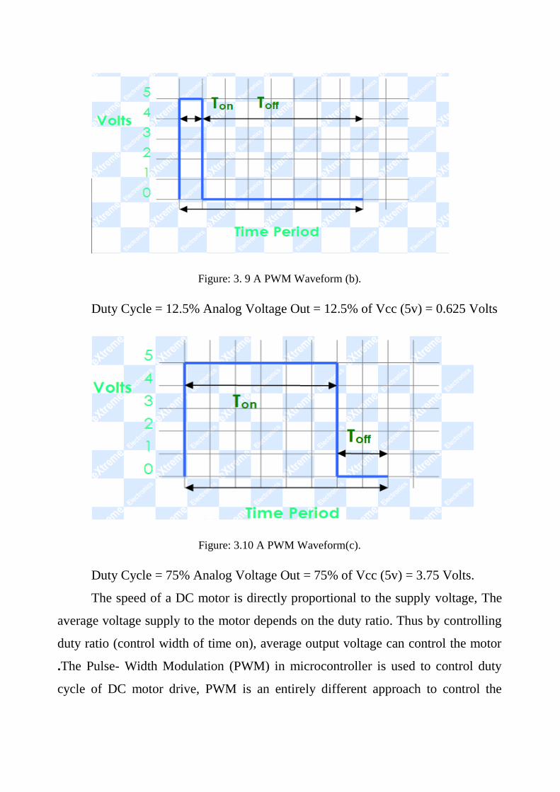
Figure: 3. 9 A PWM Waveform (b).
Duty Cycle = 12.5% Analog Voltage Out = 12.5% of Vcc (5v) = 0.625 Volts
Figure: 3.10 A PWM Waveform(c).
Duty Cycle = 75% Analog Voltage Out = 75% of Vcc (5v) = 3.75 Volts.
The speed of a DC motor is directly proportional to the supply voltage, The
average voltage supply to the motor depends on the duty ratio. Thus by controlling
duty ratio (control width of time on), average output voltage can control the motor
.The Pulse- Width Modulation (PWM) in microcontroller is used to control duty
cycle of DC motor drive, PWM is an entirely different approach to control the

speed of a DC motor. Power is supplied to the motor in square wave of constant
voltage but varying pulse-width or duty cycle.
3.3.7 ATMEGA 16
ATmega16 is an 8-bit high performance microcontroller of Atmel‟s
Mega AVR family with low power consumption. Atmega16 is based on enhanced
RISC (Reduced Instruction Set Computing, Know more about RISC and CISC
Architecture) architecture with 131 powerful instructions. Most of the instructions
execute in one machine cycle. Atmega16 can work on a maximum frequency of
16MHz.
ATmega16 has 16 KB programmable flash memory, static RAM of 1 KB and
EEPROM of 512 Bytes. The endurance cycle of flash memory and EEPROM is
10,000 and 100,000, respectively.
ATmega16 is a 40 pin MCU. There are 32 I/O (input/output) lines which are
divided into four 8-bit ports designated as PORTA, PORTB, PORTC and PORTD.
The feedback of sensor (555timer) connected to pin1 (XCK/T0) PB0 the pin
work like Counter to calculate the number of pulses incoming the duration of any
pulse is constant 1.08 ms .
Calculate of distance by Multiply the number of pulse with duration of pulse
the distance in Millimeter convert in meter by division 1*10-3 ,After that Multiply
the result with Speed of sound 340 and distance the result by 2 Because of the
distance incidence signal and reflected signal due object .
In pin 40 (ADC0) PA0 we have switch the switch Allows the signal of sensor
Pass to microcontroller when pin 40 no signal feed to microcontroller.
microcontroller have some cases depend on distance, when on object Before
a car microcontroller pin 19 (OC1A) PD5 PWM Channel Outputs control of speed
Through ULN2003A and can Slow down motor when the object nearby and the
PWM make 0 if Really very near object, when a car accident microcontroller use

pin 14 (RXD) PD0 to Receive location from GPS TX (Virtual Terminal) and
transmit by pin 15 (TXD) PD1 to GPS RX (Virtual Terminal) all due max 232.
all these Activities Display by LCD 16*2 ,LCD various interfaces (8-bit/4-
bit), and have 8 Data bus line Here 4 line Just use (D4,D5,D6,D7) all this JTAG
Interface.
D4 connect with pin 26 PC4 (TDO), D5 connect with pin 27 PC5 (TDI),
D6 connect with 28 PC6 (TOSC1), D6 connect with 29 PC7 (TOSC2), and pin 6
(E) connected with pin 22 PC0 (SCL).
Pin 5 (RW),pin 3 (VDD ),pin 1 (Vss) in LCD connected with Ground ,pin2
connected with VCC , Pins connections descriptions in ATMEGA 16 is show in
table 3.5.
Table 3.5: Pins connections descriptions in ATMEGA 16.
NAME PURPOSE
Port A Pin A.0: connected to switch.
Port B Pin B.0: connected to sensor (555 timer) T0: Timer0 External
Counter Input.
Port C Port C is an 8-bit bi-directional I/O port with internal pull-up
resistors (selected
For each bit).
In system designed used port C to connected LCD
Port D Pin D.5 PWM Channel Outputs to motor Through ULN2003A
3.4 control system Flow charts and state Diagram:
The flow charts show in figure 3.7 illustrate the general flow
Chart of the control system, the number indicate the conditions.

NO
Figure: 3.11 General flow chart.
Start
sensor calculate
the distance
if safe mode
YES
NO
step down motor &
sensor calculate
the distance
If warning zone
YES
GPS Specify the location
&GSM sent to police
station
initialization

CHAPTER FOUR
SIMULATION AND RESULT

4. SIMULATION AND RESUIL
In this chapter the system that where described in chapter three would be tested
classified through simulation, Circuit will be described .The output of sensor
income for the microcontroller, and there by control the output.
We have six scenarios all scenarios Depends on The distance and connected to Pin
A.0 Condition is closed.
4.2ReadDestance:
After reading the number of pulses incoming, Distance are displayed
on the screen after calculations.
The relationship between the number of pulses and the distance show in Table 4.1
Table 4.1: The relationship between the number of pulses and the distance.

NUMBER OF PULSES DISTANCE IN CM
996 79
2234 :5
2552 221
2998 256
3151 267
5155 422
4.1.1 Scenario 1:
The distance between the Object and the car is very close, its 68cm (less than
100cm is danger) this inevitably means an accident. The LCD display that as
“Danger zone” with a lighting of a red LED, sound alarm (buzzer).also the GPS
(Virtual Terminal) Orders you enter the location and GSM (Virtual Terminal)
Displays or sends the location. Here will inevitably be the speed of the motor is
zero
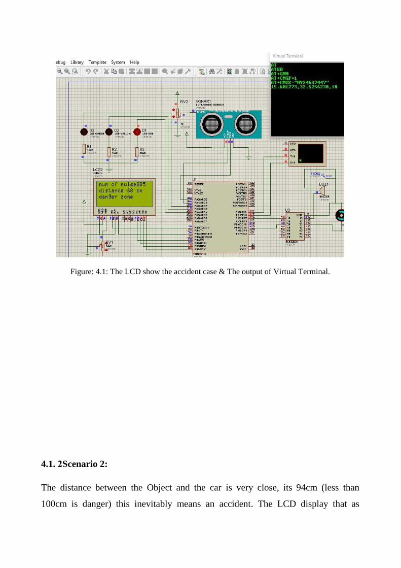
Figure: 4.1: The LCD show the accident case & The output of Virtual Terminal.
4.1. 2 Scenario 2:
The distance between the Object and the car is very close, its 94cm (less than
100cm is danger) this inevitably means an accident. The LCD display that as

“Danger zone” with a lighting of a red LED, sound alarm (buzzer).also the GPS
(Virtual Terminal) Orders you enter the location and GSM (Virtual Terminal)
Displays or sends the location. Here will inevitably be the speed of the motor is
zero.
Figure: 4.2: The LCD show the accident case & The output of Virtual Terminal.
4.1.3 Scenario 3:
The distance between the Object and the car is Acceptable its 110cm (between100-
151 cm), But with a probability of danger so the speed of motor will be reduced, the
LCD display that as “warning zone” with a lighting of a yellow LED.

Figure: 4.3: The LCD show the medium distance.
4.1.4 Scenario 4:
The distance between the Object and the car is Acceptable its 145cm (between100-
151cm), But with a probability of danger so the speed of motor will be reduced, the
LCD display that as “warning zone” with a lighting of a yellow LED.

Figure: 4.4 The LCD show the warning zone.
4.1.5 Scenario 5:
The distance between the Object and the car is safe its 156 cm (above 150cm
is safe), the Speed motor can become high. And the LCD displays that as
“safe zone” with a lighting of a green LED.

Figure: 4.5 The LCD show the safe zone.
4.1.6 Scenario 6:
The distance between the Object and the car is safe its 311 cm (above 150cm
is safe), the Speed motor can become high. And the LCD displays that as
“safe zone” with a lighting of a green LED.
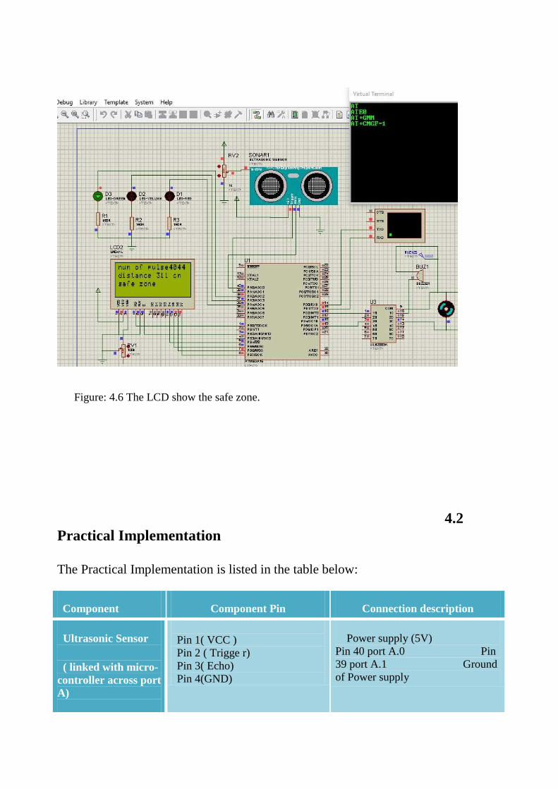
Figure: 4.6 The LCD show the safe zone.
4.2
Practical Implementation
The Practical Implementation is listed in the table below:
Component Component Pin Connection description
Ultrasonic Sensor
( linked with micro-
controller across port
A)
Pin 1( VCC )
Pin 2 ( Trigge r)
Pin 3( Echo)
Pin 4(GND)
Power supply (5V)
Pin 40 port A.0 Pin
39 port A.1 Ground
of Power supply

LCD
(Linked with
micro- controller
across port B).
pin 1 (VSS)
pin 2 ( VDD) Pin
3 ( VEE) Pin 4
(RS) Pin 5
(RW) Pin 6 (E)
D4
D5
D6
D7
Ground
Power supply(5V)
Variable resistance Pin
1 PB0 (XCK) Ground
Pin 3 PB2
(AINO) Pin 5 PB4 (SS)
Pin 6 PB5 (MOSI)
Pin 7 PB6 (MISO)
Pin 8 PB7 (SCK)
ULN2003A
(Linked with
microcontroller
across
port D & used to
Interface between a
microcontroller and
motor and buzzer).
1B
4B
COM and3C
COM and 1C
Pin 16 PD 2 (IN T0)
Pin 19 PD 5 (OC1A)
First motor & Second motor,
which are connected in parallel
Buzzer (which Alarm
in case Object closer
(danger zone)
GSM& GPS module
(SIM 900)
TX
RX
Pin 14 PD0 (RX).
Pin 15 PD1 (TX).

CHAPTER FIVE
CONCLUSIONS AND RECOMMENDATION

5. CONCLUSIONS AND RECOMMENDATION
5.1 Conclusions:
In this project an intelligent collision avoidance system. Was built based on
an ATMEGA16L microcontroller able to interface with the sensor and COM1 9 pin
(hardware interface) and interface with the user with LCD rather to the
accompanying simulation .the microcontroller has been programmed to work as the
controller of the Avoid the accident incident knowing Report the accident location.
At the end of the project, the circuit module has been successfully
constructed and demonstrated, has achieved the objective where the system is
intended to prevent the accident during driving Based on distance detected and
control condition by sensor in front of the car adjust the speed of vehicle to
establish a safe stopping distance.
The accident position factor is very important for saving lives
By location Detection system and sending the accident position.
Based on software and algorithms support, could operate well within an
expected performance. However, the models development still has some limitation.
Several suggestions for the future improvement are proposed in the following
section.

5.2 Recommendation:
This project is recommended for whoever wants to continue in this side
because it's very important to execute in real time as in bigger aspects. This is
recommended to look in time in order to achieve the wanted results and the
objective goals.
Suggested Future work:
Increase the number of sensor.
Add Camera work video call for the hospital to find out the number of
injured and the quality of injury.
Instead of using GPS (delay) can be used as the sender of which cell
(tower) number to specify the location.
Implement more efficient braking method to reduce the time for the car to
stop.
Use high range sensor that more accurate and less sensitive to
disturbances.

REFERENCES:
[1] P. Papadimitratos, L. Buttyan, T. Holczer, E. Schoch, J. Freudiger, M. Raya,
et al., "Secure vehicular communication systems: design and architecture,"
Communications Magazine, IEEE, vol. 46, pp. 100-109, 2008.
[2] R. Monisha, J. J. Leo, and B. T. S. Sakthi, "Car Authentication and Accident
Intimation System Using GPS and GSM."
[3] N. Thakor, T. Vyas, D. Shah, M. Tank, M. Patel, M. Amipar, et al.,
"Automatic Vehicle Accident Detection System Based on ARM &GPS,"
International Journal for Research in Technological Studies, vol. 1, 2013.
[4] A. R. Carbone, F. Di Fusco, and D. Carbone, "Electronic accident estimating
system," ed: Google Patents, 1992.
[5] L. Yang, J. H. Yang, E. Feron, and V. Kulkarni, "Development of a
performance-based approach for a rear-end collision warning and avoidance
system for automobiles," in Intelligent Vehicles Symposium, 2003.
Proceedings. IEEE, 2003, pp. 316-321.
[6] R. Bergholz, K. Timm, and H. Weisser, "Autonomous vehicle arrangement
and method for controlling an autonomous vehicle," ed: Google Patents,
2000.
[7] T. A. S. Kumar and J. Mrudula, "Advanced Accident Avoidance System for
Automobiles."
[8] S. K. C. Varma and T. V. H. Poornesh, "Automatic Vehicle Accident
Detection And Messaging System Using GPS and GSM Modems,"
International Journal of Scientific & Engineering Research, vol. 4, 2013.
[9] A. Nieto and K. Dagdelen, "Development and testing of a vehicle collision
avoidance system based on GPS and wireless networks for open-pit mines,"
Application of Computers and Operations Research in the Minerals
Industries, 2003.
[10] K. Nandaniya, V. Choksi, A. Patel, and M. B Potdar, "Automatic Accident
Alert and Safety System using Embedded GSM Interface," International
Journal of Computer Applications, vol. 85, pp. 26-30, 2014.
[11] S. N. Gujar and J. R. Panchal, "Smart car system using Sensor, GPS and
GSM," ICST-2K14, vol. 2, 2014.
[12] R. Nazir, A. Tariq, S. Murawwat, and S. Rabbani, "Accident Prevention and
Reporting System Using GSM (SIM 900D) and GPS (NMEA 0183)," Int'l J.
of Communications, Network and System Sciences, vol. 7, p. 286, 2014.
[13] S. Sonika, K. SATHIYASEKAR, and S. JAISHREE, "Intelligent accident
identification system using GPS, GSM modem," traffic, vol. 3, 2014.
[14] M. S. Amin, J. Jalil, and M. Reaz, "Accident detection and reporting system
using GPS, GPRS and GSM technology," in Informatics, Electronics &
Vision (ICIEV), 2012 International Conference on, 2012, pp. 640-643.

Appendix “A”

$regfile = "m16def.dat"
$crystal = 8000000
$baud = 19200
'------------------------------------------------------
Config Com1 = Dummy , Synchrone = 0 , Parity = None , Stopbits = 1 , Databits =
8 , Clockpol = 0
Config Lcd = 16 * 4
Config Lcdpin = Pin , Db4 = Portb.4 , Db5 = Portb.5 , Db6 = Portb.6
Db7 = Portb.7 , E = Portb.2 , Rs = Portb.0
Config Timer1 = Pwm , Pwm = 8 , Compare A Pwm = Clear Up
Prescale = 1
'------------------------------------------------------
Pwm1a = 200
Dim Gps As String * 200
Gps = "15.601273,32.5256238,18"
'------------------------------------------------------
Config Pina.0 = Input 'echo
Config Porta.1 = Output 'triggr
Config Portd.2 = Output 'buzzer
Config Portd.4 = Output 'motor
Config Portd.5 = Output 'motor
Config Porta.2 = Output 'led g
Config Porta.3 = Output 'led y
Config Porta.4 = Output 'led r
'------------------------------------------------------
Dim S1 As Long
Dim Cm1 As Long
Dim Sr As String * 200
Dim I As Word
'------------------------------------------------------
Sr = "AT+CMGS="
Sr = Sr + Chr(&H22)
Sr = Sr + "0924637447" ' '
Sr = Sr + Chr(&H22)
'------------------------------------------------------

Cls
Lcd "WAITING GSM"
Waitms 8
Cls
Lcd " start checking "
Waitms 8
Print "AT" 'TEST
Waitms 1
Print "ATE0" 'OFF DABLL CHER
Waitms 1
Print "AT+GMM" 'MODEL
Waitms 1
Print "AT+CMGF=1" 'ASCII
Waitms 1
'------------------------------------------------------
Do
Gosub Ultrsonic1
Cls
Locate 1 , 1
Lcd "num of pulse" ; S1
Locate 2 , 1
Lcd "distance " ; Cm1 ; " cm"
'------------------------------------------------------
If Cm1 >= 151 Then
Waitms 20
Locate 3 , 1
Lcd "safe zone"
Cursor Off
Portd.2 = 0
Pwm1a = 400
Porta.2 = 1
Porta.3 = 0
Porta.4 = 0
Waitms 1
S1 = 0
Waitms 100
End If
'------------------------------------------------------

If Cm1 >= 101 And Cm1 =< 150 Then
Locate 3, 1
Lcd "warning zone"
Cursor Off
Portd.2 = 0
Pwm1a = 300
Porta.2 = 0
Porta.3 = 1
Porta.4 = 0
Waitms 1
S1 = 0
Waitms 100
End If
'------------------------------------------------------
If Cm1 <= 100 Then
Locate 3 , 1
Lcd "danger zone"
Cursor Off
Portd.2 = 1
Pwm1a = 200
Porta.2 = 0
Porta.3 = 0
Porta.4 = 1
Waitms 1
S1 = 0
Print Sr
Waitms 1
Print Gps
Waitms 1
Printbin &H1A
Waitms 1
End If
'------------------------------------------------------
Loop
Ultrsonic1:
Ff1:

Porta.1 = 0
Waitus 100
Porta.1 = 1
Waitus 10
Porta.1 = 0
If Pina.0 = 0 Then
Gosub Ff1
End If
'------------------------------------------------------
Dd1:
If Pina.0 = 1 Then
Incr S1
Goto Dd1
End If
'------------------------------------------------------
Cm1 = S1 / 13
'------------------------------------------------------
Return
End

APPANDENCE „B‟

..
.
ULN2001A-ULN2002A
ULN2003A-ULN2004A
.SEVEN DARLINGTONS PER PACKAGE OUTPUT
CURRENT 500mA PER DRIVER (600mA PEAK)
OUTPUT VOLTAGE 50V
INTEGRATED SUPPRESSION DIODES FOR INDUCTIVE LOADS
OUTPUTS CAN BE PARALLELED FOR HIGHER CURRENT
TTL/CMOS/PMOS/DTL COMPATIBLE INPUTS
INPUTS PINNED OPPOSITE OUTPUTS TO
SEVEN DARLINGTON ARRAYS
SIMPLIFY LAYOUT
2.1 DESCRIPTION
The ULN2001A, ULN2002A, ULN2003 and
ULN2004A are high voltage, high current darlington arrays each containing seven open collector dar- lington pairs with common emitters. Each channel rated at 500mA and can withstand peak currents of 600mA. Suppression diodes are included for induc- tive load driving and the inputs are pinned opposite the outputs to simplify board layout.
The four versions interface to all common logic fami- lies :
2.2 PIN CONNECTION
ULN2001A General Purpose, DTL, TTL, PMOS, CMOS
ULN2002A 14-25V PMOS
ULN2003A 5V TTL, CMOS
ULN2004A 6–15V CMOS, PMOS
These versatile devices are useful for driving a wide range of loads including solenoids, relays DC mo- tors, LED displays filament lamps, thermal print- heads and high power buffers.
The ULN2001A/2002A/2003A and 2004A are sup- plied in 16 pin plastic DIP packages with a copper leadframe to reduce thermal resistance. They are available also in small outline package (SO-16) as ULN2001D/2002D/2003D/2004D
®
DIP16
ORDERING NUMBERS: ULN2001A/2A/3A/4A
SO16
ORDERING NUMBERS: ULN2001D/2D/3D/4D
..
.

81
2.3 SCHEMATIC DIAGRAM
ABSOLUTE MAXIMUM RATINGS
Symbol Parameter Value Unit
Vo Output Voltage 50 V
Vin Input Voltage (for ULN2002A/D - 2003A/D - 2004A/D) 30 V
Ic Continuous Collector Current 500 mA
Ib Continuous Base Current 25 mA
Tamb Operating Ambient Temperature Range – 20 to 85 C
Tstg Storage Temperature Range – 55 to 150 C
Tj Junction Temperature 150 C
THERMAL DATA
Symbol Parameter DIP16 SO16 Unit
Rth j-amb Thermal Resistance Junction-ambient Max. 70 120 C/W
Series ULN-2001A (each driver)
Series ULN-2002A (each driver)
Series ULN-2003A (each driver)
Series ULN-2004A (each driver)

82
APPANDENCE „C‟

83
3 Features • High-performance, Low-power Atmel® AVR® 8-bit Microcontroller
• Advanced RISC Architecture
– 131 Powerful Instructions – Most Single-clock Cycle Execution
– 32 × 8 General Purpose Working Registers
– Fully Static Operation
– Up to 16 MIPS Throughput at 16 MHz
– On-chip 2-cycle Multiplier
• High Endurance Non-volatile Memory segments
– 16 Kbytes of In-System Self-programmable Flash program memory
– 512 Bytes EEPROM
– 1 Kbyte Internal SRAM
– Write/Erase Cycles: 10,000 Flash/100,000 EEPROM
– Data retention: 20 years at 85°C/100 years at 25°C(1)
– Optional Boot Code Section with
Independent Lock Bits In-System
Programming by On-chip Boot Program
True Read-While-Write Operation
– Programming Lock for Software Security
• JTAG (IEEE std. 1149.1 Compliant) Interface
– Boundary-scan Capabilities According to the JTAG Standard
– Extensive On-chip Debug Support
– Programming of Flash, EEPROM, Fuses, and Lock Bits through the JTAG
Interface
• Peripheral Features
– Two 8-bit Timer/Counters with Separate Prescalers and Compare Modes
– One 16-bit Timer/Counter with Separate Prescaler,
Compare Mode, and Capture Mode
– Real Time Counter with Separate Oscillator
– Four PWM Channels
– 8-channel, 10-bit ADC
8 Single-ended Channels
7 Differential Channels in TQFP Package Only
2 Differential Channels with Programmable Gain at 1x, 10x, or 200x
– Byte-oriented Two-wire Serial Interface
– Master/Slave SPI Serial Interface
– Programmable Watchdog Timer with Separate On-chip Oscillator
– On-chip Analog Comparator
• Special Microcontroller Features
– Power-on Reset and Programmable Brown-out Detection
– Internal Calibrated RC Oscillator
– External and Internal Interrupt Sources
– Six Sleep Modes: Idle, ADC Noise Reduction, Power-save,
Power-down, Standby and Extended Standby
• I/O and Packages
– 32 Programmable I/O Lines
– 40-pin PDIP, 44-lead TQFP, and 44-pad QFN/MLF
• Operating Voltages
– 2.7V - 5.5V for ATmega16L
– 4.5V - 5.5V for ATmega16
• Speed Grades
– 0 - 8 MHz for ATmega16L
– 0 - 16 MHz for ATmega16
• Power Consumption @ 1 MHz, 3V, and 25C for ATmega16L
– Active: 1.1 mA
– Programmable Serial USART
8-bit
Microcontroller
with 16K Bytes
In-System
Programmable
Flash
ATmega16
ATmega16L
Summary
Rev. 2466TS–AVR–07/10

84
– Idle Mode: 0.35 mA
– Power-down Mode: < 1 µA
4 Pin
Configurations
Figure 1. Pinout ATmega16
PDIP
(XCK/T0) PB0
(T1) PB1
(INT2/AIN0) PB2
(OC0/AIN1) PB3
(SS) PB4
(MOSI) PB5
(MISO) PB6
(SCK) PB7
RESET
VCC
GND
XTAL2
XTAL1
(RXD) PD0
(TXD) PD1
(INT0) PD2
(INT1) PD3
(OC1B) PD4
(OC1A) PD5
(ICP1) PD6
PA0 (ADC0)
PA1 (ADC1)
PA2 (ADC2)
PA3 (ADC3)
PA4 (ADC4)
PA5 (ADC5)
PA6 (ADC6)
PA7 (ADC7)
AREF
GND
AVCC
PC7 (TOSC2)
PC6 (TOSC1)
PC5 (TDI)
PC4 (TDO)
PC3 (TMS)
PC2 (TCK)
PC1 (SDA)
PC0 (SCL)
PD7 (OC2)
TQFP/QFN/MLF
(MOSI) PB5
(MISO) PB6
(SCK) PB7
RESET
VCC
GND
XTAL2
XTAL1
(RXD) PD0
(TXD) PD1
(INT0) PD2
PA4 (ADC4)
PA5 (ADC5)
PA6 (ADC6)
PA7 (ADC7)
AREF
GND
AVCC
PC7 (TOSC2)
PC6 (TOSC1)
PC5 (TDI)
PC4 (TDO)
NOTE: Bottom pad should be soldered to ground.
PB
4 (S
S)
PB
3
(AIN
1/O
C0
)
PB
2
(AIN
0/I
NT
2)
PB
1 (T
1)
PB
0 (X
CK
/T0
)
GN
D
VC
C
PA
0
(AD
C0
)
PA
1
(AD
C1
)
PA
2
(AD
C2
)
PA
3 (A
DC
3)
(IN
T1
) P
D3
(OC
1B
) P
D4
(OC
1A
) P
D5
(IC
P1
) P
D6
(OC
2)
PD
7
VC
C
GN
D
(SC
L)
PC
0
(SD
A)
PC
1
(TC
K)
PC
2
(TM
S)
PC
3

ATmega16(L)
85
2466TS–AVR–07/10
Disclaimer Typical values contained in this datasheet are based on simulations and
characterization of other AVR microcontrollers manufactured on the same process
technology. Min and Max values will be available after the device is characterized.

ATmega16(L)
86
2466TS–AVR–07/10
PROGRAM
COUNTER
STACK
POINTER
PROGRAM
FLASH
INSTRUCTION
REGISTER
GENERAL
PURPOSE
REGISTERS
X
Y
Z
SPI
INTERNAL
OSCILLATOR
WATCHDOG
TIMER
INTERNAL
CALIBRATED
OSCILLATOR
OSCILLATOR
OSCILLATOR
PORTA DRIVERS/BUFFERS PORTC DRIVERS/BUFFERS
GND PORTA DIGITAL INTERFACE PORTC DIGITAL INTERFACE
AVCC
MUX &
ADC
ADC
INTERFACE
AREF
XTAL1
XTAL2
INSTRUCTION
DECODER
MCU CTRL.
& TIMING RESET
CONTROL
LINES ALU INTERRUPT
UNIT
AVR CPU
PROGRAMMING LOGIC
+
-
PORTB DIGITAL INTERFACE
PORTB DRIVERS/BUFFERS
TWI
SRAM
STATUS
REGISTER
COMP.
INTERFACE
TIMERS/
COUNTERS
EEPROM
USART
PORTD DIGITAL INTERFACE
PORTD DRIVERS/BUFFERS
Overview The ATmega16 is a low-power CMOS 8-bit microcontroller based on the AVR
enhanced RISC architecture. By executing powerful instructions in a single clock
cycle, the ATmega16 achieves throughputs approaching 1 MIPS per MHz allowing the
system designer to optimize power con- sumption versus processing speed.
Block Diagram Figure 2. Block Diagram
PA0 - PA7 PC0 - PC7
VCC
PB0 - PB7 PD0 - PD7

`
87