Double spin-echo sequence for rapid spectroscopic imaging of hyperpolarized< sup> 13 C
Upload
khangminh22Category
view
3download
0
I
Preface
Thank you for purchasing our ultrasonic flow meter. Please read this manualcarefully before operating and using it correctly to avoid unnecessary lossescaused by false operation.Note
Modification of this manual’s contents will not be notified as a result ofsome factors, such as function upgrading.
We try our best to guarantee that the manual content is accurate, if you findsomething wrong or incorrect, please contact us.
This product is forbidden to use in explosion-proof occasions.
VersionU-JCS1158-MYEN2

II
Safety PrecautionsIn order to use this product safely, be sure to follow the safety precautionsdescribed.About this manual
Please submit this manual to the operator for reading. Please read the operation manual carefully before applying the instrument.
On the precondition of full understanding. This manual only describes the functions of the product. The company
does not guarantee that the product will be suitable for a particular use bythe user.
Precautions for protection, safety and modification of this product
To ensure safety of this product and the systems it controls, Please readcarefully the operation manual and understand the correct applicationmethods before putting into operation, to avoid unnecessary losses due tooperation mistakes. If the instrument is operated in other ways notdescribed in the manual, the protections that the instrument give may bedestroyed, and the failures and accidents incurred due to violation ofprecautions shall not be borne by our company.
When installing lightning protection devices for this product and its controlsystem, or designing and installing separate safety protection circuits forthis product and its control system, it needs to be implemented by otherdevices.
If you need to replace parts of the product, please use the modelspecifications specified by the company.
This product is not intended for use in systems that are directly related topersonal safety.Such as nuclear power equipment, equipment usingradioactivity, railway systems, aviation equipment, marine equipment,aviation equipment and medical equipment.If applied, it is the responsibilityof the user to use additional equipment or systems to ensure personalsafety.

III
Do not modify this product. The following safety signs are used in this manual:
Hazard, if not taken with appropriate precautions, will result in seriouspersonal injury, product damage or major property damage.
Warning:Pay special attention to the important information linked toproduct or particular part in the operation manual.
Confirm if the supply voltage is in consistent with the rated voltagebefore operation.
Don’t use the instrument in a flammable and combustible or steam area. To prevent from electric shock, operation mistake, a good grounding
protection must be made. Thunder prevention engineering facilities must be well managed: the
shared grounding network shall be grounded at is-electric level,shielded, wires shall be located rationally, SPD surge protector shall beapplied properly.
Some inner parts may carry high voltage. Do not open the square panelin the front except our company personnel or maintenance personnelacknowledged by our company, to avoid electric shock.
Cut off electric powers before making any checks, to avoid electricshock.
Check the condition of the terminal screws regularly. If it is loose, pleasetighten it before use.
It is not allowed to disassemble, process, modify or repair the productwithout authorization, otherwise it may cause abnormal operation,electric shock or fire accident.
Wipe the product with a dry cotton cloth. Do not use alcohol, benzine or

IV
other organic solvents. Prevent all kinds of liquid from splashing on theproduct. If the product falls into the water, please cut off the powerimmediately, otherwise there will be leakage, electric shock or even afire accident.
Please check the grounding protection status regularly. Do not operate ifyou think that the protection measures such as grounding protection andfuses are not perfect.
Ventilation holes on the product housing must be kept clear to avoidmalfunctions due to high temperatures, abnormal operation, shortenedlife and fire.
Please strictly follow the instructions in this manual, otherwise theproduct's protective device may be damaged.
Don’t use the instrument if it is found damaged or deformed at openingof package.
Prevent dust, wire end, iron fines or other objects from entering theinstrument during installation, otherwise, it will cause abnormalmovement or failure.
During operation, to modify configuration, signal output, start up, stop,operation safety shall be fully considered. Operation mistakes may leadto failure and even destruction of the instrument and controlledequipment.
Each part of the instrument has a certain lifetime, which must bemaintained and repaired on a regular basis for long-time use.
The product shall be scrapped as industrial wastes, to preventenvironment pollution.
When not using this product, be sure to turn off the power switch. If you find smoke from the product, smell odor, abnormal noise, etc.,
please turn off the power switch immediately and contact the companyin time.

V
Disclaimer
The company does not make any guarantees for the terms outside thescope of this product warranty.
This company is not responsible for damage to the instrument or loss ofparts or unpredictable damage caused directly or indirectly by improperoperation of the user.
After opening the box, please confirm the package contents before starting theoperation.If you find that the model and quantity are incorrect or there is physicaldamage in appearance, please contact us.
No. Name Quantity Note
1 Ultrasonic flow meter 1
2 Manual 1
3 Certificate 1

VI
ContentsChapter 1 Installation..........................................................................................................1
1.1. Inspection prior to transmitter Installation........................................................21.2. Wire Connecting.................................................................................................3
1.2.1. Power supply option................................................................................ 31.2.2. To ensure the transmitter can work normally, please pay attentionto the followings when wiring: Ensure that power connections are madein accordance with the specifications shown on the transmitter..................31.2.3. Transmitter wiring.....................................................................................31.2.4. Lengthened cable method......................................................................4
1.3. Powering on......................................................................................................... 51.4. Keypad functions.................................................................................................51.5. Key operation.......................................................................................................61.6. flowmeter window description........................................................................... 8
Chapter 2 Pipe parameter entry shortcuts....................................................................102.1. Dual function keys menu description............................................................. 102.2. Examples............................................................................................................12
Chapter 3 Measurement site selection..........................................................................14Chapter 4 Transducer installation.................................................................................. 16
4.1. Installing the transducers.................................................................................164.1.1. Transducer spacing...............................................................................164.1.2. Transducer mounting methods............................................................164.1.3. V method.................................................................................................174.1.4. Z method................................................................................................. 174.1.5. N method.................................................................................................18
4.2. Transducer mounting inspection.....................................................................184.2.1. Signal strength....................................................................................... 194.2.2. Signal quality (Q value).........................................................................194.2.3. Total time and delta time...................................................................... 194.2.4. Transit time ratio.................................................................................... 204.2.5. Warnings................................................................................................. 20

VII
Chapter 5 Operating instructions....................................................................................215.1. System normal indentification......................................................................... 215.2. Zero set calibration.......................................................................................... 215.3. Scale factor........................................................................................................ 225.4. System lock........................................................................................................225.5. Frequency output.............................................................................................. 235.6. 4~20mA current loop output verification (optional)......................................235.7. Recover the factory default..............................................................................245.8. 4~20mA analog output calibration..................................................................245.9. ESN..................................................................................................................... 25
Chapter 6 Manual Zero Point Windows display codes.............................................256.1. Windows display codes....................................................................................256.2. Display explanation...........................................................................................26
Chapter 7 Troubleshooting..............................................................................................517.1. Table 1. Error codes and solutions.................................................................527.2. FAQ..................................................................................................................... 53
Chapter 8 Product overview............................................................................................548.1. Introduction.........................................................................................................548.2. Features..............................................................................................................548.3. Specification.......................................................................................................55
Chapter 9 Appendix-Serial interface network use and communications protocol..569.1. Overview.............................................................................................................569.2. Direct connection via RS-485 to the host device.........................................579.3. Communication protocol and the use............................................................ 57
9.3.1. FUJI protocol.......................................................................................... 579.3.2. MODBUS communication protocol..................................................... 60
Chapter 10 Appendix2-Insertion transducer.................................................................6710.1. Overview...........................................................................................................6710.2. Measurement point selection........................................................................6710.3. Determining transducer spacing& transducer installation........................6810.4. Transducer mounting methods.....................................................................69
10.4.1. Z mounting method............................................................................. 70

VIII
10.4.2. Pipe parameter entry shortcuts......................................................... 71Chapter 11 Appendix3-RTD module and PT100 wiring (modul optional)................73
11.1. RTD energy meter function..........................................................................7311.2. Wiring (PT1000)..............................................................................................7311.3. Energy measurement methods.....................................................................7411.4. Temperature calibration methods.................................................................7411.5. Installation of RTD module............................................................................76
Chapter 12 Appendix4-CG clamp-on transducers and the installation methods...7712.1. Overview...........................................................................................................7712.2. Measurement site selection...........................................................................7712.3. Installation methods........................................................................................7712.4. Examples..........................................................................................................79
Chapter 1 Installation
www.supmea.com - 1 -
Chapter 1 Installation
Please read this section when installing this product.
Installation precautions The installation method of this product is threaded installation/flange
installation. In order to prevent the internal temperature of this product from rising,
please install it in a well-ventilated location .
Avoid the following location during installation Location where sunlight directly hits and near hot appliances Location where the ambient temperature exceeds 60℃ during work
Location where the ambient humidity exceeds 85% at work Near the electromagnetic generation source Location with strong mechanical vibration Location with high temperature changes and easy condensation Location with high quantities of lampblack, steam, moisture, dust and
corrosive gases

Chapter 1 Installation
www.supmea.com- 2 -
86mm
3.39lnch
1.1. Inspection prior to transmitter Installation
You will find a "Position Drawing" in the packing. Please use it as a template in theplace that you are going to install the flowmeter. Then drill 4 installing holes at thescrews position shown on the drawing with the 5.0mm drill.
Take out the enclosed screws and plastic bushings. Insert the plastic bushingsinto the installing holes. Put the flowmeter to the position and screw it in.
135 mm5.32lnch
Position drawing
1. Place this template on the wall anddrill 4 holes of 5mm diameter &40mmdeep.
2. Insert a plastic bushing into each ofthe 4 holes.
3. Screw 4 pcs PA 4×30mm selftapping screws through thetransmitter enclosure base andattach it to thewall.
4. Tighten the screws to secure tothe enclosure on the wall.
135mm5.32lnch
MODEL: D116G
Digital Correlation Transit -Timeflowmeter

Chapter 1 Installation
www.supmea.com - 3 -
1.2. Wire Connecting1.2.1. Power supply option
Customers should pay special attention to specify the desired power supply whenwiring. Factory standard power supply is 10~36VDC/1A max.
1.2.2.To ensure the transmitter can work normally, please pay attentionto the followings when wiring: Ensure that power connections are made inaccordance with the specifications shown on the transmitter.
1.2.3. Transmitter wiringOnce the electronics enclosure has been installed, the flowmeter wiring can beconnected. Open the case, you will find the transmitter interfaces labels from leftto right as follows:Power supply, Relay output, OCT Output, Upstream transducer, Downstreamtransducer, 4-20mA, RS485 interface.Refer to the below diagram for specific connection:
AttentionWhen installing please ensure the front cover is secure and will not fall open.

Chapter 1 Installation
www.supmea.com- 4 -
1.2.4. Lengthened cable method
Standard cable length of sensor is 9 meters; it can be lengthened to be 300meters according to the actual need for fluid measurement.
1.2.4.1. Sketch of lengthened cable
1.2.4.2. Junction Box Requirements
The flowmeter use sealed waterproof junction box, installing 6×2 press-connections, the recommended minimum specifications of the junction box is115×90×55mm.
1.2.4.3. Cable specifications
Name: Shielded Twisted Pair
Administer Standard: JB8734.5-1998
Diameter: Φ5 mm
Twist Line Space: 50 mm
Multi Core Line: 0.4 mm2/radix

Chapter 1 Installation
www.supmea.com - 5 -
Wire Guage: AWG 20#
Core Line Color: Red and Black
Shield Floor: 128 Intwine
1.3. Powering on
As soon as the flowmeter is switched on, the self-diagnosis program will start torun. If any error is detected, an error code will display on the screen (Refer - ErrorDiagnoses). After that self-diagnosis, the system will run automatically accordingto the last input parameters.If the installation is accomplished when system is switched on, gain adjustmentcan be monitored in Window M01. After S1, S2, S3, S4 are displayed on the upperleft corner of the screen, the system will activate the normal measurementcondition automatically. It is indicated by code "*R" on the upper left corner of thescreen.If it is the first time to use or install on a new site, the customer need to input thenew installation site parameters. The system will default to the last windowsettings and automatically display them at next power on.
1.4. Keypad functions
This keypad is dual function keypad:1.When separately pressed, is shortcut function, referring to "2. Quickly set menuinstructions ";
2.Press and Number key, is Menu key, referring to"6.Menu WindowDescription".Follow these guidelines when using the flowmeter keypad (Refer to KeypadFigure):
~ And To input numbers.
WarningWire with power off. The flow meter must be reliable grounding before installation.

Chapter 1 Installation
www.supmea.com- 6 -
Backspace or delete characters to the left.And Return to the last menu or to open the
next menu. Acts as "+" and "-" functions when entering numbers.
Select a menu. Press this key first, input two menu numbers and then enterthe selected menu. For example, to input a pipe outside diameter, press
keys, where "11" is the window ID to display the parameter forpipe outside diameter.
1.5. Key operation
The flow meter adopts the window software design to consolidate or subdivide allof the parameters entered, the instrument setup and measurement result displaysinto more than 100 independent windows. The operator can input parameters,modify settings or display measurement results by "visiting" a specific window.These windows are arranged by 2-digit serial numbers (including "+" sign) from00~99, then to +0, +1, etc. Each window serial number, or so-called window IDcode, has a defined meaning. For example, Window M11 indicates the parameterinput for pipe outside diameter, while Window M25 indicates the mounting spacingbetween the transducers, etc. (Refer – Windows Display Explanations).
The keypad shortcut to visit a specific window is to press the key at any time,then input the 2-digit window ID code. For example, to input or check the pipe

Chapter 1 Installation
www.supmea.com - 7 -
outside diameter, just press the keys for window ID code 11.Another method to visit a particular window is to press and keys toscroll the screen. For example, if the current window ID code is M02, presskey to enter Window M01, press the button again to enter Window M00; then,press the key to back Window M01, and press the ˅ key again to enterWindow M02.Windows are separated into three types: (1) Data Type, such as M11, M12; (2)Option Type, such as M14; (3) Pure Display Type, such as M01, M00.You can check the corresponding parameters by visiting the Data Type Windows.If you want to modify the parameters, input the digits and press or press
first, input the digits then press Enter again to confirm.
Example1: To enter a pipe outside diameter of 219.234, the procedure is asfollows:Press keys to enter Window M11 (the numerical value displayedcurrently is a previous value). Now press key. The symbol ">" and theflashing cursor are displayed at the left end of the second line on the Screen. Theninput the parameters; or do not press the key, directly enter
.
You can check the selected option by visiting Option Type Windows. If you want tomodify it, you must press first, the symbol ">" and the flashing cursor aredisplayed at the left of the Screen. Operator can use the and to scrollthe screen and get the required value then press to confirm; or enter thecorresponding value option directly and press to confirm.

Chapter 1 Installation
www.supmea.com- 8 -
For example, if the pipe material is "Stainless Steel", Press to enterWindow M14, press to modify the options. Select the "1. Stainless Steel"option by pressing and , then press to confirm the selection; It ispossible to press key to change the selection and wait until"1.StainlessSteel" is displayed on the second line of the screen, then press to confirm.
1.6. flowmeter window description
These windows are assigned as follows:01~08 Flow Totalizer Display: to display flow rate, positive total, negative total,
net total, velocity, date & time, present operation and flow results today,etc.
10~29 Initial Parameter Setup: to enter pipe outside diameter, pipe wallthickness, fluid type, transducer type, transducer mounting method andspacing, etc.
30~38 Flow Units Options: to select the flow unit such as cubic meter, liter orother units, can turn totalizers on/off and reset totalizers, etc.
40~49 Setup options: Scaling factor, system lock (Window M47), etc.55~89 Input and output setup: date and time, ESN, communication baud rate
setting, etc.90~98 Diagnoses: Signal strength and signal quality (Window M90),
TOM/TOS*100 (Window M91), flow sound velocity (Window M92), totaltime and delta time (Window M93), Reynolds number and factor (WindowM94), etc.
+0~+5 Appendix: power on/off time, total working hours, on/off times and asingle-accuracy function calculator.
AttentionGenerally, press key first if operator wants to enter “modify” status. If the “modify” is still notpossible even after pressing the key, it means that system is locked by a password. To“Unlock” it, select “Unlock” in Window M47 and enter the original password.

Chapter 1 Installation
www.supmea.com - 9 -
AttentionThe other windows for hadware adjustment are reserved by the manufacturer.

Chapter 2 Pipe parameter entry shortcuts
www.supmea.com- 10 -
Chapter 2 Pipe parameter entry shortcuts
2.1. Dual function keys menu description
Press keyDisplay Net Flow Today /Flow Max/Flow Min/The Average/Current Ratein turn.
Press keyDisplay Day Totalizer Flow/MonthlyTotalizer Flow/ Yearly Totalizer Flowin turn.
Press keyDisplay Totalizer Start and Stop in turn.
Press keyDisplay instantaneous cool capacityand cool capacity totalizer.
Press keyDisplay instantaneous heat capacityand heat capacity totalizer.
Press keyDisplay the temp in, out andtemperature difference .
Press keyDisplay Flow Rate and Velocity.
Press keyDisplay Flow Rate and Velocity.
Flow Max.360 .0000 m3/h
m3Day Totalizer
700.1000
m360 sec 10.123
ON
EFR 0.0000 GJ/ h* RENT 0X1 GJ
I n-Out- Delta C6.21 8.21 - 2.00
EFR 0.0000 GJ/ h* REPT 0X1 GJ
Flow 0.1129m3/h*RVel 1.0415 m/s
Flow 0.1129m3/h*RVel 1.0415 m/s

Chapter 2 Pipe parameter entry shortcuts
www.supmea.com - 11 -
Press keyDisplay Flow Sound Velocity.
Press keyDisplay Signal Strength and SignalQuality.
Press keyPress Ent to start Manual Totalizer,then press Ent to end Manual Totalizer,press Ent to input Standard Totalizer toget the final K factor. Complete thecalibration with pressing Ent to store.
Press keyInput Code 1234 to complete ResetZero.
Press keyDisplay System Error Codes.
Fluid Sound Velocity 0.0000m/ s
Strength + Quality [ 90UP:00.0 DN:00.0 Q=00
Manual Cali bratePress Ent When Ready
* R- - - - -- - --System Normal
Set ZeroPlease Enter PW

Chapter 2 Pipe parameter entry shortcuts
www.supmea.com- 12 -
2.2. ExamplesFor example, measuring the diameter of 219mm and pipe wall thickness of 6mm,measuring medium is water, Pipe Material is carbon steel, No Liner, can beoperated as follows:
Step1. Pipe outside diameter:
Press keys to enterWindow M11, and enter the pipeoutside diameter, and then press the
key to confirm.
Step2. Pipe wall thickness
Press the keys to enterWindow M12, and enter the pipe wall
thickness, and press the key toconfirm.
Step3. Pipe Material
Press the keys to enter
Window M14, press the key,press the or key to selectPipe Material, and press the Enterkey toconfirm.
Pipe Outer Diameter219mm
Pipe Wall Thickness6mm
Pipe Material [14 0.CarbonSteel

Chapter 2 Pipe parameter entry shortcuts
www.supmea.com - 13 -
Step4. Transducer type(The transmitter is available forvarioustransducer types.)
Press the key to enter
Window M23,press the key,move the or key to selecttransducer type,and press the
key to confirm.
Step5. Transducer mounting methods
Press the key toenter
Window M24, press the key,press the or key to selecttransducer-mounting method, andpress the Enter key to confirm.
Step6. Adjust Transducer spacing
Press the key to enterWindow M25, accurately install thetransducer according to the displayedtransducer mounting spacing and theselected mounting method (Refer toInstalling the Transducers in thischapter).
Transducer Type[23 0. Standard
Transducer Mounting0. V
Tranducer Spacing177.01 mm

Chapter 3 Measurements site selection
www.supmea.com- 14 -
Chapter 3 Measurement site selection
When selecting a measurement site, it is important to select an area where thefluid flow profile is fully developed to guarantee a highly accurate measurement.Use the following guidelines to select a proper installation site: Choose a sectionof pipe that is always full of liquid, such as a vertical pipe with flow in the upwarddirection or a full horizontal pipe. Ensure enough straight pipe length at least equalto the figure shown below for the upstream and downstream transducersinstallation. Select a fluid-filled section, such as a vertical section of the line (upward flow
is preferred) or a horizontal section filled with fluid. The measuring point should be within 10 diameters (10D) of the upstream
and 5 diameters (5D) of the downstream, without any devices such as valves,elbows and diameters interfering with the flow field.The length of straight pipeis recommended as shown in FIG. 6.
On the horizontal pipe section, the sensor should be installed at 9 o 'clockand 3 o 'clock of the pipe and should avoid the position at 6 o 'clock and 12 o'clock, so as to avoid the attenuation of the signal caused by the sediment atthe bottom of the pipe or the bubbles and cavitation at the top of the pipe.
Make sure the temperature at the measuring point is within the working range. Full consideration should be given to the condition of scale formation on the
inner wall of the pipe, and the tube section without scale should be selectedfor measurement as far as possible. If it cannot be completely satisfied, thescale formation should be considered as the lining in order to obtain bettermeasurement accuracy.
Select the tube segment with uniform density and easy ultrasonictransmission.
Ensure that the pipe surface temperature at the measuring point is within thetransducer temperature limits. Consider the inside condition of the pipe carefully. Ifpossible, select a section of pipe where the inside is free of excessive corrosion orscaling.

Chapter 3 Measurement site selection
www.supmea.com - 15 -

Chapter 4 Transducer installation
www.supmea.com- 16 -
Chapter 4 Transducer installation4.1. Installing the transducers
Before installing the transducers, clean the pipe surface where the transducers areto be mounted. Remove any rust, scale or loose paint and make a smooth surface.Choose a section of sound conducting pipe for installing the transducers. Apply awide band of sonic coupling compound down the center of the face of eachtransducer as well as on the pipe surface, ensure there are no air bubblesbetween the transducers and the pipe wall, and then attach the transducers to thepipe with the straps provided and tighten them securely.
Note:1. The two transducers should be mounted at the pipe’s centerline on horizontalpipes. Make sure that the transducer mounting direction is parallel with the flow.
2. During the installation, there should be no air bubbles or particles between thetransducer and the pipe wall. On horizontal pipes, the transducers should bemounted in the 3 o’clock and 9 o’clock positions of the pipe section in order toavoid any air bubbles inside the top portion of the pipe. (Refer to TransducerMounting).
3. If the transducers cannot be mounted horizontally symmetrically due tolimitation of the local installation conditions, it may be necessary to mount thetransducers at a location where there is a guaranteed full pipe condition (thepipe is always full of liquid).
4.1.1. Transducer spacingAfter entering the required parameters, the spacing between the ENDS of the twotransducers is considered as the standard transducer spacing (Refer to Top Viewon transducer mounting methods). Check the data displayed in Window M25 andspace the transducers accordingly.
4.1.2. Transducer mounting methodsThree transducer mounting methods are available. They are respectively: V

Chapter 4 Transducer installation
www.supmea.com - 17 -
method, Z method and N method. The V method is primarily used on smalldiameter pipes (DN100~300mm, 4〞 ~12〞 ). The Z method is used in
applications where the V method cannot work due to poor signal or no signaldetected. In addition, the Z method generally works better on larger diameterpipes (over DN300mm, 12〞) or cast iron pipes.
The N method is an uncommonly used method. It is used on smaller diameterpipes (below DN50mm, 2〞).
4.1.3. V methodThe V method is considered as the standard method. It usually gives a moreaccurate reading and is used on pipe diameters ranging from 25mm to 400mm(1"~16〞 ) approximately. Also, it is convenient to use, but still requires proper
installation of the transducers, contact on the pipe at the pipe’s centerline andequal spacing on either side of the centerline.
4.1.4. Z methodThe signal transmitted in a Z method installation has less attenuation than a signaltransmitted with the V method when the pipes are too large, there are somesuspended solid in the fluid, or the scaling and liner are too thick .This is becausethe Z method utilizes a directly transmitted (rather than reflected) signal whichtransverses the liquid only once.The Z method is able to measure on pipe diameters ranging from 100mm to800mm (4〞~32〞) approximately. Therefore, we recommend the Z method forpipe diameters over 300mm (12〞).
Chapter 4 Transducer installation
www.supmea.com- 18 -
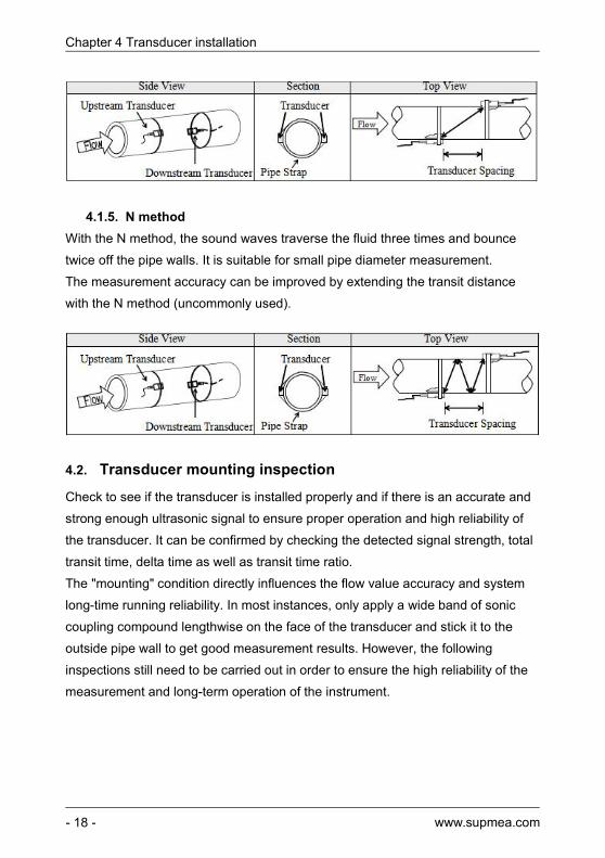
4.1.5. N methodWith the N method, the sound waves traverse the fluid three times and bouncetwice off the pipe walls. It is suitable for small pipe diameter measurement.The measurement accuracy can be improved by extending the transit distancewith the N method (uncommonly used).
4.2. Transducer mounting inspectionCheck to see if the transducer is installed properly and if there is an accurate andstrong enough ultrasonic signal to ensure proper operation and high reliability ofthe transducer. It can be confirmed by checking the detected signal strength, totaltransit time, delta time as well as transit time ratio.The "mounting" condition directly influences the flow value accuracy and systemlong-time running reliability. In most instances, only apply a wide band of soniccoupling compound lengthwise on the face of the transducer and stick it to theoutside pipe wall to get good measurement results. However, the followinginspections still need to be carried out in order to ensure the high reliability of themeasurement and long-term operation of the instrument.

Chapter 4 Transducer installation
www.supmea.com - 19 -
4.2.1. Signal strengthSignal strength (displayed in Window M90) indicates a detected strength of thesignal both from upstream and downstream directions. The relevant signalstrength is indicated by numbers from 00.0~99.9. 00.0 represents no signaldetected while 99.9 represents maximum signal strength.
Normally, the stronger the signal strength detected, the longer the operation of theinstrument reliably, as well as the more stable the measurement value obtained.Adjust the transducer to the best position and check to ensure that enough soniccoupling compound is applied adequately during installation in order to obtain themaximum signal strength.
System normally requires signal strength over 60.0, which is detected from bothupstream and downstream directions. If the signal strength detected is too low, thetransducer installation position and the transducer mounting spacing should be re-adjusted and the pipe should be re-inspected. If necessary, change the mountingmethod to be Z method.
4.2.2. Signal quality (Q value)Q value is short for Signal Quality (displayed in Window M90). It indicates the levelof the signal detected. Q value is indicated by numbers from 00~99. 00 representsthe minimum signal detected while 99 represent the maximum.Normally, the transducer position should be adjusted repeatedly and couplingcompound application should be checked frequently until the signal qualitydetected is as strong as possible.
4.2.3. Total time and delta time"Total Time and Delta Time", which displays in Window M93, indicates thecondition of the installation. The measurement calculations in the flowmeter arebased upon these two parameters. Therefore, when "Delta Time" fluctuates widely,the flow and velocities fluctuate accordingly, this means that the signal qualitydetected is too poor. It may be the resulted of poor pipe-installation conditions,

Chapter 4 Transducer installation
www.supmea.com- 20 -
inadequate transducer installation or incorrect parameter input.Generally, "Delta Time" fluctuation should be less than ±20%. Only when the pipediameter is too small or velocity is too low can the fluctuation be wider.
4.2.4. Transit time ratioTransit Time Ratio indicates if the transducer mounting spacing is accurate. Thenormal transit time ratio should be 100+/-3 if the installation is proper. Check it inWindow M91.
4.2.5. Warnings(1) Pipe parameters entered must be accurate; otherwise the flowmeter will not
work properly.(2) During the installation, apply enough coupling compounds in order to stick the
transducers onto the pipe wall. While checking the signal strength and Qvalue, move the transducers slowly around the mounting site until thestrongest signal and maximum Q value can be obtained. Make sure that thelarger the pipe diameter, the more the transducers should be moved.
(3) Check to be sure the mounting spacing is accordance with the display inWindow M25 and the transducer is mounted at the pipe’s centerline on thesame diameter.
(4) Pay special attention to those pipes that formed by steel rolls (pipe withseams), since such pipe is always irregular. If the signal strength is alwaysdisplayed as 0.00, that means there is no signal detected. Thus, it isnecessary to check that the parameters (including all the pipe parameters)have been entered accurately. Check to be sure the transducer mounting
AttentionIf the transit time ratio is over 100±3,it is necessary to check:(1) If the parameters(pipe outside diameter,wall thickness,pipe material,line, etc.) have been
entered correctly,(2) If the transducer mounting spacing is accordance with the display in Windows M25,(3) If the transducer is mounted at the pipe’s centerline on the same diameter,(4) If the scale is too thick or the pipe mounting is distorted in shape, etc.

Chapter 5 Operating instructions
www.supmea.com - 21 -
(5) method has been selected properly, the pipe is not worn-out, and the liner isnot too thick. Make sure there is indeed fluid in the pipe or the transducer isnot too close to a valve or elbow, and there are not too many air bubbles inthe fluid, etc. With the exception of these reasons, if there is still no signaldetected, the measurement site has to be changed.
(6) Make sure that the flowmeter is able to run properly with high reliability. Thestronger the signal strength displayed, the higher the Q value reached. Thelonger the flowmeter runs accurately, the higher the reliability of the flow ratesdisplayed. If there is interference from ambient electromagnetic waves or thesignal detected is too poor, the flow value displayed is not reliable;consequently, the capability for reliable operation is reduced.
(7) After the installation is complete, power on the instrument and check theresult accordingly.
Chapter 5 Operating instructions5.1. System normal indentification
Press the keys. If the letter "*R" displays on the screen, itindicates system normal.If the letter "G" is displayed, it indicates that system is adjusting the signal gainprior to the measurement. Also, it means system normal. Only when theadjustment takes too long without stopping, can system be identified as abnormal.Letter "I" indicates no signal is being detected. Check the transducer wiringconnections are correct, the transducers are installed firmly, etc.
5.2. Zero set calibration
Once zero flow occurs, a zero point may indicate on each measuring instrument,but the displayed measuring value is not equal to "0", this value indicates "Zero".To any measuring instrument, the smaller the "Zero" is, the better the quality is.Conversely, if the Zero is too big, that indicates the quality of the instrument ispoor.If the zero set point is not at true zero flow, a measurement difference may occur.The smaller the physical measurement capacity is, the larger the measurement

Chapter 5 Operating instructions
www.supmea.com- 22 -
difference from the zero point will exist. Only when zero point reduced to a definitedegree, as compared with the physical measurement capacity, can the measuringdifference from zero point be ignored.For an ultrasonic flowmeter, the measurement difference from zero point cannotbe ignored at low flow. It is necessary to perform a static zero set calibration toimprove low flow measurement accuracy.Press Window M42 to set the Zero, press first, and then wait the readingsdisplayed at the lower right corner reducing to be "0". If this is carried out with flow,the flow will be displayed as "0", M43 can help to restore settings.
5.3. Scale factor
Scale factor refers to the ratio between "actual value" and "reading value". Forexample, when the measurement and is 2.00, and it is indicated as 1.98 on theinstrument, the scale factor reading is 2/1.98. This means that the best scalefactor constant is 1.However, it is difficult to keep the scale factor as "1" on the instrument especiallyin batch productions. The difference is called "consistency".During operation, there still exists possible difference in pipe parameters, etc. The"scale factor" may be necessary when used on different pipes. Thus, scale factorcalibration is specially designed for calibrating the differences that result fromapplication on different pipes. The scale factor entered must be one that resultsfrom actual calibration. The scale factor can be input in Window M45.
5.4. System lock
System lock is readable but not modifiable to prevent operation error due tounauthorized tampering by unauthorized personnel.
Press the keys, if displays "Unlock" on the screen, then
press the key, enter 6 numerically long password, and then press the Enterkey to confirm.
Unlock it by using the selected password only. Press , if "lock" is
displayed on the screen, then press the key and enter the correct password,

Chapter 5 Operating instructions
www.supmea.com - 23 -
RL1 RL2 OCT+ OCT- E UP+ UP-RELAY OCT OUT TRANS
COM
Vcc5~10K1/4w Sig
then press Enter to confirm.Keep the password in mind or recorded in a safe place, otherwise the instrumentcannot be used.
5.5. Frequency output
The flowmeter is provided with a frequency output transmitter function. The high orlow frequency output displayed indicates the high or low flow rate reading. Theuser can reset the frequency output as well as flow rate as his requirements.For example: if a pipe flow range is 0~3000m3/h, the relative frequency outputrequired is 0~5000Hz, and the configuration is as follows:In Window M68 (low limit frequency output flow value), input 0;In Window M69 (high limit frequency output flow value), input 3000; Typical OCTOutput wiring diagram as below:
5.6. 4~20mA current loop output verification (optional)
Processing a current loop output exceeding an accuracy of 0.1%, the flowmeter isprogrammable and configurable with multiple output modes such as flow rate orfluid velocity. Select in Window M55. For details, please refer to "Windows DisplayExplanations".In Window M56, enter a 4mA flow rate or fluid velocity value. Enter the 20mA flowrate or fluid velocity value in Window M57. For example, if the flow range in a

Chapter 5 Operating instructions
www.supmea.com- 24 -
specific pipe is 0~1000m3/h, enter 0 in Window M56 and 1000 in Window M57.Calibrating and testing the current loop is performed in Window M58. Completethe steps as follows:
Press , move or to display "0mA", "4mA","8mA", "12mA","16mA", "20mA" readings, connect an ammeter to test the currentloop output and calculate the difference. Calibrate it if the difference is withintolerance. If the difference is without tolerance, refer to the "Analog OutputCalibration" to calibrate the current loop.Check the present current loop output in Window M59 as it changes along withchange in flow.5.7. Recover the factory default
Press keys to Window m37, press or key tochoose “Reset” keys to recover the factory default.
5.8. 4~20mA analog output calibration
The hardware detect window must be activated prior to calibration the AnalogOutput. The procedure is as follows:
Press enter password "115800", then press Enter toactivate the detect menu. With no effect to next power on, this window will closeautomatically as soon as the power is turned off.
Press to calibrate the current loop 4mA output. Use an ammeter tomeasure the current loop output current.
At the same time, press or to adjust the displayed numbers. Watchthe ammeter until it reads 4.00. Stop at this point, the 4mA has been calibrated.
Then, press to calibrate the current loop 20mA output. The method is thesame as 4mA calibration. The results are automatically saved in EEPROM andwon’t lose when power off.
NoteEach flowmeter has been calibrated strictly before leaving factory. It is unneccessary to carrythrough this step except when the current value (detected while calibrating the current loop)displayed in Window M58 is not identical with the actual output current value.

Chapter 6 Manual Zero Point Windows display codes
www.supmea.com - 25 -
5.9. ESN
We provide the flowmeter with a unique electronic serial number to identify eachflowmeter for the convenience of the manufacturer and customers. The ESN isable to be viewed in Window M61.
Chapter 6 Manual Zero Point Windows display codes
6.1. Windows display codes
Flow Totalizer Display 32 Totalizer Units 72 Working Timer00 Flow Rate/Net Total 33 Totalizer Multiplier 77 Beeper Setup01 Flow Rate/Velocity 35 POS Totalizer 78 OCT Output Setup02 Flow Rate/POS
Totalizer36 NEG Totalizer 79 Relay Output Setup
03 Flow Rate/NEG Total 37 Totalizer Reset 82 Date Totalizer04 Date Time/Flow Rate 38 Manual Totalizer 83 Automatic Correction05 Instantaneous Heat
Capacity / TotalizerHeat Capacity
Setup Options84 Energy Units Options
06 Instantaneous CoolCapacity/ TotalizerCool Capacity
40 Damping 86 Delta TemperatureSensitivity Settings
07 Inlet Water Temp/Outlet Water Temp /Delta Temp.
41 Low Flow CutoffValue
42 Set Static Zero 87 Energy TotalizerON/OFF
08 System Error Codes 43 Reset Zero 88 Energy TotalizerMultiplier
09 Net Flow Today 44 Manual Zero Point 89 Reset EnergyTotalizer
Initial Parameter setup 45 Scale Factor Diagnoses
AttentionOther Operation refers to “7.2 Windows Display Explanations”.

Chapter 6 Manual Zero Point Windows display codes
www.supmea.com- 26 -
11 Pipe Outer Diameter 46 Network identifyingaddress code
90 Signal Strength andQuality
12 Pipe Wall Thickness 91 TOM/TOS*10014 Pipe Material 47 System Lock 92 Fluid Sound Velocity23 Transducer Type Input and output setup 93 Total Time and Delta
55 CL Mode Select 94 Reynolds Numberand Factor24 Transducer Mounting
Method56 CL 4mA Output
Value25 Transducer Spacing 57 CL 20mA Output
Value97 Transducer Spacing
correction selection26 Parameters Setups 58 CL Check27 Cross-sectional Area 59 CL Current Output Appendix28 Holding with Poor
Sig60 Date and Time +0 Last Power Off Time
and Flow Rate29 Empty Pipe Setup 61 ESN30 Metric system Units 62 Serial Port
Parameter+1 Total Working Hours
31 Flow Rate Units 67 FO FrequencyRange
+2 Last Power Off Time
Flow Units Options 68 Low FO Flow Rate +3 Last Flow Rate30 Metric system Units 69 High FO Flow Rate +4 Total Power Off
Times31 Flow Rate Units 70 LCD Backlit Option -0 Hardware Adjusting
Entry
NOTE:The other menu features are retained by manufacturers and the windows ingray background are optional functions
6.2. Display explanation
Display Flow Rate/Net TotalFlow 0.1154 m3/h * RNET 0x 1 m3
Display Flow Rate and Velocity.Flow 0.1129 m3/h * RVel 1.0415 m3

Chapter 6 Manual Zero Point Windows display codes
www.supmea.com - 27 -
Flow Rate /POS TotalizerDisplay Flow Rate and POSTotalizer.Select the POSTotalizer units in Window M31.If the POS Totalizer has beenturned off, the POS Totalizervalue displayed is the total priorto its turn off.
Flow 0.1129 m3/h * RPOS 0x1 m3
Flow Rate/NEG TotalDisplay Flow Rate and NEG TotalSelect the NEG Total units in WindowM31.If the NEG Total has been turnedoff, the NEG Total value displayed isthe total prior to its turn off.
Date Time/Flow RateThe time setting method can be foundin WindowM60.
Heat Capacity / Totalizer HeatCapacityDisplay Instantaneous Heat CapacityAnd Totalizer Heat Capacity.NetEnergy Totalizer: E.T; InstantaneousEnergy: EFR.Note : when the instrument is named
03- 04 - 03 15 :49:40 *RFlow 0.116 m3/h
GJ0X10.0000 GJ/h* IEFR
EPT
m30x10.1120 m3/h *R
FlowNEG

Chapter 6 Manual Zero Point Windows display codes
www.supmea.com- 28 -
energy meter: Heat Capacity: "[P",Cool Capacity: "[N".
Cool Capacity / Totalizer CoolCapacityDisplay Instantaneous Cool Capacityand Totalizer Cool Capacity.
System Error CodesDisplay the Working Condition andthe System Error Codes. More thanone error code can occur at the sametime.The explanations of error codesand detailed resolution methods canbe found in "Error Diagnoses"
System Error CodesDisplay the Working Condition and theSystem Error Codes. More than oneerror code can occur at the sametime.The explanations of error codesand detailed resolution methods canbe found in "Error Diagnoses".
Net Flow TodayDisplay Net Flow Today.
[09m3
POS Flow Today0.458748
* R- - - -- - - -- -- - --System Normal
GJ0X10.0000 GJ/h* IEFR
ENT
0.00Tn- Out- Delta C
0.00 0.00

Chapter 6 Manual Zero Point Windows display codes
www.supmea.com - 29 -
Pipe Outer DiameterEnter the pipe outside diameter orenter the pipe circumference inWindow M10. The pipe outsidediameter must range from 10mm to6000mm. Note: Enter either pipeoutside diameter or pipecircumference.
Enter the pipe wall thickness
Pipe MaterialEnter pipe material. The followingoptions are available(by 、 buttons or numerical
keys)
Transducer Type0. Standard(clamp-on typetransducer)1. Type-45B(W210 type insertiontransducer)
Pipe Wall Thickness4.00 mm
0. CarbonSteel
[14Pipe Material
Pipe OuterDiameter
50mm

Chapter 6 Manual Zero Point Windows display codes
www.supmea.com- 30 -
Transducer MountingFour mounting methods are available:0. V1. Z2. N
Transducer SpacingThe operator must mount thetransducer according to thetransducer spacing displayed (be surethat the transducer spacing must bemeasuredprecisely during installation). Thesystem will display the dataautomatically after the pipe parameterhad been entered.
Initial Parameter Setups and SaveLoad and save the parameters.18 different sets of setup conditions/groups are available to load and saveby three methods0. Entry to Save1. Entry to Load2. To BrowseSelect "Entry to Save", press .An ID code and the originalparameters are displayed in thewindow. Press UP or DOWN ARROW
Parameter SetupsEntry to
SAVE
TransducerMounting 0.V
Tranducer Spaci ng148.66 mm

Chapter 6 Manual Zero Point Windows display codes
www.supmea.com - 31 -
to move the ID code, then press theEnter key again to save the currentparameter in the current ID room.When selecting "Entry to Load", pressENT, and the system will read andcalculate the parameters automaticallyand display the transducer mountingspacing in Window M25.
Cross-sectional Area
Holding with Poor SigSelect "Yes" to hold last good flowsignal displayed if the flowmeterexperiences a poor signalcondition.This function will allow tocalculate flow totalizer data withoutinterruption.Select "NO", instead.
Empty Pipe SetupThis parameter is used to overcomethe possible problems that usuallyshow up when the pipe beingmeasured is empty. Since signals canbe transmitted through the pipe wall,the flow meter may still read a flowwhile measuring an empty pipe.Toprevent this condition from happening,you can specify a value.When the
Empty Pipe Setup [290
Cross - sect ional Area314515.9 mm2
Holding with Poor SigNO

Chapter 6 Manual Zero Point Windows display codes
www.supmea.com- 32 -
signal quality falls below this value,the measurement stops automatically.If the flow meter is already able tostop measuring when the pipe isempty, a value in the range of 30 to 40should also be entered in this windowto ensure no measurement when thepipe is empty.
Measurement Units OptionsSelect the measurement unit asfollows:0. Metric1. English
Flow Rate Units OptionsThe following flow rate units areavailable:0. m3 Cubic Meters1. 1 Liters2. gal USA Gallons3. ig Imperial Gallons4. mg Million Gallons5. cf Cubic Feet6. bal USA Barrels7. Ib Imperial Barrels8. Ob Oil BarrelsThe following time units are available:/ Day / Hour/ Min / Sec
Factory default is Cubic Meters/hour
[31Flow Rate Unitem3/h
Measurement Units In0.Metric

Chapter 6 Manual Zero Point Windows display codes
www.supmea.com - 33 -
Totalizer Units OptionsSelect totalizer units. The availableunit options are as same as thosefound in Window M31. The user canselect units as their requirement.Factory default is Cubic Meters.
Totalizer Multiplier OptionsThe totalizer multiplier acts as thefunction to increase the totalizerindicating range. Meanwhile, thetotalizer multiplier can be applied tothe positive totalizer, negativetotalizer and net totalizer. Thefollowing options are available:
0. x 0.001 (1E-3)1. x 0.012. x 0.13. x 14. x 105. x 1006. x 10007. x 10000(1E+4)
Factory default factor is x1
ON/OFF POS TotalizerOn/off POS Totalizer. "NO" indicatesthe flowmeter starts to totalize thevalue. When it is turned off, the
Totalizer Multipler>0. x0.001(1E-3)
[35TotalizerYES
POS
Meters(m3)[32Uni tsTotali zer
0.Cubi c

Chapter 6 Manual Zero Point Windows display codes
www.supmea.com- 34 -
positive totalizer displays in WindowM02 will not change. Factory default is"YES".
ON/OFF NEG TotalizerOn/off NEG Totalizer. "NO" indicatesthe flowmeter starts to totalize thevalue. When it is turned off, thepositive totalizer displays in WindowM03 will not change. Factory default is"YES".
Totalizer ResetTotalizer reset; all parameters arereset. Press ;press or
arrow to select "YES" or "NO".After "YES" is selected, the followingoptions are available:
None:No reset;All:Reset all totalizers;NET Totalizer Reset;POS Totalizer Reset;NEG Totalizer Reset;
Reset:back to the factory defaultIf the user wants to delete all thealready set parameters and set backto the factory default, select reset inthis window and then the flow meterwill reset to be the factory defaultautomatically.
Totalizer Reset[37 Selection
[36NEG TotalizerYES

Chapter 6 Manual Zero Point Windows display codes
www.supmea.com - 35 -
Manual TotalizerThe manual totalizer is a separatetotalizer. Press to start, and Press
to stop it. It is used for flowmeasurement and calculation.
Damping FactorThe damping factor ranges from 0~
999 seconds.0 indicates no damping;999 indicates the maximum damping.The damping function will stabilize theflow display.Its principle is the sameas that in a single-section RC filter.The damping factor value correspondsto the circuit time constant. Usually adamping factor of 3 to 10 isrecommended in applications.
Low Flow Cut off ValueLow Flow Cut off is used to make thesystem display as "0" value at lowerand smaller flows to avoid any invalidtotalizing. For example, if the cutoffvalue is set as 0.03, system will takeall the measured flow values below±0.03 as "0". Usually 0.03 isrecommended in most applications.
[40sec10
Damping
Low Flow Cutoff Val0.01m/s
AttentionThis operation will delete the entire user’s data and reset as the factory default.Please consider carefully before taking this operation.

Chapter 6 Manual Zero Point Windows display codes
www.supmea.com- 36 -
Set Static State ZeroWhen fluid is in the static state, thedisplayed value is zcalled "ZeroPoint". When "Zero Point ’ is not atzero in the flowmeter, the difference isgoing to be added into the actual flowvalues andmeasurement.Differences will occur inthe flowmeter. Setting zero must becarried out after the transducers areinstalled and the flow inside the pipe isin the absolute static state. Thus, the"Zero Point" resulting.
Reset ZeroSelect "YES"; reset "Zero Point" whichwas set by the user.
Manual Zero PointThis method is not commonly used.It is only suitable for experiencedoperators to set zero under conditionswhen it is not preferable to use othermethods. Enter the value manually toadd to the measured value to obtainthe actual value. For example: Actualmeasured value= 250 m3/HActual measured value= 10 m3/Hflowmeter Display= 240 m3/H
Normally, set the value as "0".
[43zeroNO
Reset
Manual zero point [440.0000 m3/h
Pr ess Ent ToGo
[42Set zero

Chapter 6 Manual Zero Point Windows display codes
www.supmea.com - 37 -
Scale FactorThe scale factor named as instrumentK factor is used to modify themeasurement results. The user canenter a numerical value according tothe actual calibration results.
Network IDNInput system identifying code, thesenumbers can be selected from 1~247except that 13 (0DH EN TER), 10(0AH Newline), 42 (2AH﹡) and 38
(26H&) are reserved.System IDN isused to identify the flowmeter to anetwork.
System LockLock the instrument, Once the systemis locked, any modification to thesystem is prohibited, but theparameter is readable. "Unlock" usingyour d esignated password. Thepassword is composed of 6 numbers.
* * * * * * * UNLOCK ** * * * * *[47System LOCK
[45Scale factor1
[46I DN88
Network

Chapter 6 Manual Zero Point Windows display codes
www.supmea.com- 38 -
Current Loop Mode Select
0. 4-20mA set up the 4-20mA output to. be flow rate mode1. 0-20mA set up output range to be 0-20mA mode2. 4-20mA vs.Vel. set up the 4-20mA output to. be velocity mode3. 4-20mA vs.Energy set up current loop output 4-20mAcorresponding energyOther different current output characteristics are displayed in below figures. Theuser can select one of them according to his actual requirements.
In two graphs shown above, flow F4mA indicates the value that the user enteredin Window M57; and flow F20mA indicates the value that the user entered inWindow M58. In the 4-20mA modes, F4mAand F20mA can be selected as apositive or negative flow value as long as the two values are not the same.
CL 4mA Output ValueSet the CL output value according tothe flow value at 4mA. The flowunit’s options are the same as thosein Window m31. Once "4-20mA vs.Vel."is selected in Window M56, the unitshould be set as m/s.
0. 4- 20mA
[55CL mode Select
CL 4 mA Output Value0.000 m3/h

Chapter 6 Manual Zero Point Windows display codes
www.supmea.com - 39 -
20mA Output ValueSet the CL output value accordingto the flow value at 20mA. the flowunit is the same as that found inWindow m31. Once "4-20mA vs.Vel." is selected in Window M57,the unit should be set as m/s.
CL Check VerificationCheck if the current loop hasbeen calibrated before leavingthe factory. Press to start,press or to display 0mA,4mA, 8mA, 12mA, 16mA,20mA, and atthe same time, check with an ammeterto measure the current loop outputcurrent and calculate the differences tosee if it is under the permittedtolerance.If not, refer to the "AnalogOutput Calibration" to calibrate.
CL Current Output
Display CL current output. Thedisplay of 10.0000mA indicates thatCL current output value is10.0000mA. If the difference
between displaying value and CL
CL 20mA Output Value14400.00 m3/h

Chapter 6 Manual Zero Point Windows display codes
www.supmea.com- 40 -
The factory default serial port parameteris "9600, None".
HH:MM:SS
YY:MM:DD
output value is too large, thecurrent loop then needs to be re-calibrated accordingly.
Date and Time SettingsDate and time modifications aremade in this window. The formatfor setting time setting is 24 hours.Press , wait until ">" appears, themodification can be made.
ESNDisplay electronic serial number(ESN) of the instrument. This ESNis the only one assigned to eachflowmeter ready to leave the factory. Thefactory uses it for files setup and theuser uses it for management.
Serial Port Settings
This window is used for serialport setting. Serial port is used tocommunicate with otherinstruments. The serial portparameters setting of theinstrument that applies the serialport connection must beconsistence. The first selected
RS485 Setup9600 None

Chapter 6 Manual Zero Point Windows display codes
www.supmea.com - 41 -
data indicates baud rate, 9600,19200, 38400, 56000, 57600,115200 are available.
The second optionindicates parity bit, None(No verification).Datalength fixed to 8;Stop bitlength for a fixed length.
FO Frequency RangeSet the highest limit of the outputSignal frequency. highest limitfrequency values must be greaterthan the lower frequency range:1-9999Hz,Factory default:1~1001Hz.
Note: output frequency signaloutput from OCT mouth, so tooutput frequency signal, must alsoBe set OCT into frequency signaloutput mode(M78 choose 0. FO).
Low FO Flow RateSet up low FO flow rate, i.e. thecorresponding flow value whenoutput signal frequency is at thelowest FO frequency. For example,when the low FO frequency is 0 Hz,low FO flow rate is 100m3/h thenwhen the frequency output is 0 Hz,
FO Fr equency Range1-5000
High FO Flow Rate [ 6926550 m3/h

Chapter 6 Manual Zero Point Windows display codes
www.supmea.com- 42 -
High FO Flow RateEnter the high FO flow rate, i.e.the corresponding flow value whenfrequency output signal is at highest FOfrequency. For example, when the lowFOfrequency is 5000Hz, low FO flow rate is1000m3/h,then when the frequencyoutput is 5000Hz, the low flow at thismoment measured by the flowmeter is1000m3/h.
Low FO Flow Rate [ 680.0000 m3 / h
LCD Back lit OptionSelect LCD back lit controls.
0. Always OFF1. Always ON2. Lighting For nn sec
Keep the backlight off can saveabout 30mA power.
Working TimerDisplay the totalized workinghours of the flowmeter since last reset. Itis displayed by HH:MM:SS. If it isnecessary toreset it, press , and select "YES".
the low flow at this momentmeasured by the flowmeter is 100m3/h.
45:04:59[72Working time

Chapter 6 Manual Zero Point Windows display codes
www.supmea.com - 43 -
Beeper SetupSet up the beeper on-off state.
0. ONBeeper ON1. OFF Beeper OFF
OCT Output SetupSet OCT output hardware unitoutput trigger sources, selectionof triggering events:0.No Signal 1.Alarm #12. Alarm #2 3. NET Int Pulse
4.Energy Pulse 5.FO
Relay Output SetupThe relay is single-pole andconstant-on for externalinstrument controls. Thefollowing options are available:
0.Not Ready (No*R) 1.Alarm#1
2.Alarm#2 3.NET Int Pulse
[77
BEEPERSetup
OCT Output Setup[ 78 5.FO
RELAY OutputSetup3.NET I nt Puls e

Chapter 6 Manual Zero Point Windows display codes
www.supmea.com- 44 -
Date TotalizerIn this window, it is possible toreview the historical flow datatotalizer for any day of the last64 days, any month of the last64 months and any year of thelast 5 years.Press , use theor to review totalizer in days,months and years. "0" for day, "1" formonth, "2" for year.Use the or to review thetotalizer in some day, some month,some year.For example, to display theflow total for July 18,2000, the display ""at the upper right corner of the screenindicates that it was working properly thewhole day. On the contrary, if "G" isdisplayed, it indicates that theinstrument gain was adjusted at leastonce. Probably it was offline once onthat day. If "H" is displayed, it indicatesthat poor signal was detected at leastonce. Also, it indicates that the operationwas interrupted or problems occurred inthe installation.For more informationplease refer to "Error Code andResolutions".
[82Date Totali zer0 .Day
00 03- 04 - 05 - - - - -->4356.78 m3
00 03- 04 - 05 G- H-I- 0 m3

Chapter 6 Manual Zero Point Windows display codes
www.supmea.com - 45 -
Automatic Flow CorrectionWith the function of automatic flowcorrection, the flow lost in an offlinesession can be estimated andautomatically adjusted. The estimate isbased on the average value, which isobtained from flow rate before goingoffline and flow measured after goingonline the next time, multiplied times thetime period that the meter was offline.Select "ON" to use this function and"OFF" to cancel this function.
Energy Units OptionsSelect Energy Units. The factorydefault unit is GJ. The followingoptions are available:
The following units of time are available:/day ( per day ); /hour ( per hour ); /min( per minute );/sec ( per second ). Thefactory default unit is /hour.
0.Giga Joule (GJ)1.Kilocalorie (Kcal)
2.MBtu 3.Kilojoule (KJ)
4.Btu 5.KWh
6.MWh
Ener gy Uni ts SelectGJ/h
Automatic Correct ionYES

Chapter 6 Manual Zero Point Windows display codes
www.supmea.com- 46 -
Temperature sensitivity and user SHCWhen the delta temperature is less thanthe sensitivity set,, energy will not beaccumulated. Set the adjustabletemperature range of 0℃ to 10℃.The factory default setting is 0.2℃
When the user specific heat is setting,energy is accumulated according to theuser specific heat value. The settingrange is from 1 to 99999 KJ/m3 C.Thefactory default is 4186.8KJ/m3C.
Energy Totalizer SwitchSelect "ON" represent to open EnergyTotalizer; Select "OFF" represent toclose Energy Totalizer.
Energy MultiplierSelect Energy Multiplier range:10-3 ~ 104 (E-3 ~ E4)
Reset Energy TotalizerSelect "YES" to reset EnergyTotalizer value.
Reset Ener gy TotalNO
Ener gy Totali zer[87 ON
Temperature Delicacy0.20 C
Energy Multiplier [883. x1 =(EO)

Chapter 6 Manual Zero Point Windows display codes
www.supmea.com - 47 -
Signal Strength and Signal QualityDisplay the measured signal strengthand signal quality Q value upstream anddownstream. Signal strength is indicatedfrom00.0~99.9. A reading of 00.0 indicatesno signal detected,while 99.9 indicates maximum signalstrength. Normally the signal strengthshould be ≥60.0. Signal quality Q isindicated by 00~99.Therefore, 00
indicates the poorest signal while 99indicates the best signal.Normally, signalquality Q value should be better than50.During the installation,pay attention to the signal strengthand signal quality, the higher, thebetter. The strong signal strengthand high quality value can ensurethe long-term stability and the highaccuracy of the measurement results.
TOM/TOS*100Display the ratio between the actualmeasured transmit time and thecalculated transmit time according tocustomer’s requirement. Normally theratio should be 100±3%. If the
difference is too large, the user should
[91
Tom/Tos* 1000.00

Chapter 6 Manual Zero Point Windows display codes
www.supmea.com- 48 -
check whether the parameters areentered correctly, especially the soundvelocity of the fluid and the installation ofthe transducers. This data is of no usebefore the system is ready.
Fluid Sound VelocityDisplay the measured fluid soundvelocity.
properly or if the parametershavebeen entered correctly.
Total Time and Delta TimeDisplay the measured ultrasonicaverage time (unit: nS) and delta time ofthe upstream and downstream (unit: nS)time. The velocity calculation in theflowmeter is based on the tworeadings.The delta time is the bestindication that the instrument is runningsteadily. Normally the fluctuation in theratio of the delta time should be lowerthan 20%. If it is not, it is necessary tocheck if the transducers are installed
Fluid Sound Velocity1443.4 m/s

Chapter 6 Manual Zero Point Windows display codes
www.supmea.com - 49 -
Reynolds Number and FactorDisplay the Reynolds number that iscalculated by the flowmeter and thefactor that is set currently by theflowmeter. Normally this scaling factor isthe average of the line and surfacevelocity factor inside the pipe.
Installation spacing correctionselectionselection includes the followings:
0.OFFTurn off Installation spacingcorrection1.1.ONTurn on Installation spacingcorrection
Power ON/OFF TimeTo view the power on/off time and flowrate for the last 64 update times toobtain the offline time period and thecorresponding flow rate.Enter the
window, press and todisplay the last update before the last 64times of on/off time and flow rate values."ON" on right hand indicates that timepower is on; "00" on the upper left cornerindicates "00-07-18 12:40:12" the datetime; flow rate is displayed in the lowerright corner.
[+0ReadyPr ess ENT
When
ON/OFFTim
e00- 07 18 12:40 :12* ON 123.65 m3/ h
Spacing Cor r ection0.OFF
1.0000[94NumberReynolds
0 .0000

Chapter 6 Manual Zero Point Windows display codes
www.supmea.com- 50 -
Total Working HoursWith this function, it is possible toview the total working hours sincethe flowmeter left the factory. Thefigure on the right indicates that thetotal working hours since theflowmeter left the factory is 1107hours 1 minute 41 seconds.
Display the last power off time.
Displays the last flow rate.
Total ON/OFF TimesDisplay total on/off times sincethe flowmeter left the factory.
Hardware Parameter Adjusting EntryPlease refer to the 5.8 "4~20mA AnalogOutput Verification.
Total Wor k Hour s [+100001107:01:41
[+4ON/OFF Time40

Chapter 7 Troubleshooting
www.supmea.com - 51 -
Chapter 7 Troubleshooting
The ultrasonic flowmeter has advanced self-diagnostics functions and displaysany errors in the upper right corner of the LCD via definite codes in a date/timeorder. Hardware error diagnostics are usually performed upon each power on.Some errors can be detected during normal operation. Undetectable errorscaused by incorrect settings and unsuitable measurement conditions can bedisplayed accordingly. This function helps to detect the errors and determinecauses quickly; thus, problems can be solved in a timely manner according to thesolutions listed in the following tables.Table 1 applies when errors caused by incorrect settings and signals are detectedand are announced by error codes displayed in Window M08.

Chapter 7 Troubleshooting
www.supmea.com- 52 -
7.1. Table 1. Error codes and solutions
Code M08 Display Cause Solutions
*R SystemNormal
* System normal
Signal NotDetected
Signal not detected.Spacing is not correctbetween thetransducers or notenough couplingcompound applied toface of transducers.
Attach transducer to the pipeand tighten it securely. Applya plenty of couplingcompound on transducer andpipe wall.Remove any rust, scale, orloose paint from the pipesurface. Clean it with a file.
*I* Transducersinstalled improperly
* Check the initial parametersettings.
* Scale is too thick.* Remove the scale orchange the scaled pipesection. Normally, it ispossible to change ameasurement location. Theinstrument may run
* New pipe liner.properly at a new site withless scale.* Wait until liners solidifiedand saturated.
*GAdjusting Gain(Display inWindowsM01)
The machine isadjusting forgain,preparing fornormal calibration.

Chapter 7 Troubleshooting
www.supmea.com - 53 -
7.2. FAQ
Question: New pipe, high quality material, and all installation requirements met:why still no signal detected?
Answer: Check pipe parameter settings, installation method and wiringconnections. Confirm if the coupling compound is applied adequately, thepipe is full of liquid, transducer spacing agrees with the screen readingsand the transducers are installed in the right direction.
Question: Old pipe with heavy scale inside, no signal or poor signal detected: howcan it be resolved?
Answer: Check if the pipe is full of fluid.Try the Z method for transducer installation (If the pipe is too close to awall, or it is necessary to install the transducers on a vertical or inclinedpipe with flow upwards instead of on a horizontal pipe).Carefully select agood pipe section and fully clean it, apply a wide band of couplingcompound on each transducer face (bottom) and install the transducerproperly.Slowly and slightly move each transducer with respect to eachother around the installation point until the maximum signal is detected.Be careful that the new installation location is free of scale inside the pipeand that the pipe is concentric (not distorted) so that the sound waves donot bounce outside of the proposed area. For pipe with thick scale insideor outside, try to clean the scale off, if it is accessible from the inside.(Note: Sometimes this method might not work and sound wavetransmission is not possible because of the a layer of scale between thetransducers and pipe inside wall).
Question: Why is the flow rate still displayed as zero while there is fluid obviouslyinside the pipe and a symbol of "R" displayed on the screen?
Answer: Check to see if "Set Zero" was carried out with fluid flowing inside thepipe(Refer to Window M42). If it is confirmed, recover the factory defaultin Window M43.

Chapter 8 Product overview
www.supmea.com- 54 -
Chapter 8 Product overview
8.1. Introduction
The ultrasonic flowmeter is a state-of-the-art universal transit-time flowmeterdesigned using FPGA chip and low voltage broadband pulsetransmission.,available for measuring water.
8.2. Features
Comparing With other traditional flowmeter or ultrasonic flowmeter,it hasdistinctive features such as high precision, high reliability, high capability and lowcost, the flowmeter features other advantages:1. SLSI technology designed. Less hardware components, low voltage
broadband pulse transmission, low consumption power, high reliability, anti-jamming and outstanding applicability.
2. User-friendly menu designed. Parameters of pipe range, pipe material,pipe wall thickness, output signals, etc can be conveniently entered viathe windows. British and Metric measurement units are available.
3. Daily, monthly and yearly totalized flow: Totalized flow for the last 64 days andmonths as well as for the last 5 years are may be viewed. Power on/offfunction: allows the viewing of time and flow rate as power is switched on andoff 64 times. Also, the flowmeter has manual or automatic amendment duringoffline sessions.
4. Parallel operation of positive, negative and net flow totalizes with scale factor(span) and 7 digit display, while the output of totalize pulse and frequencyoutput are transmitted via open collector.

Chapter 8 Product overview
www.supmea.com - 55 -
8.3. Specification
Performance specifications
Flow range 0.03 ~ 16 ft/s ( 0.01 ~ 5.0 m/s ).
Accuracy ± 1.0 %.
Pipe size Clamp-on: 1” ~ 48” ( 25mm ~ 1200mm ).
Fluid Water.
Function specifications
Outputs OCT Pulse output: 0-5000Hz.Analog output : 4 ~ 20mA, max load 750Ω.
Communication interface RS485MODBUS.
Power supply 10 ~ 36VDC/1A.
Keypad 16 ( 4×4 ) key with tactile action.
Display 20×2 lattice alphanumeric, back lit LCD.
Temperature Transmitter: 14 °F to 122 °F ( –10℃ ~ 50℃ );Transducer: 32 °F to 176 °F ( 0℃ ~ 80℃ ).
Humidity Up to 99% RH, non-condensing.
Physical specifications
Transmitter PC/ABS, IP65.
Transducer Encapsulated design, IP68.
transducer cable Standard cable length: 30 ft (9m).
Weight Transmitter: approximately 0.7kg; Transducer:approximately 0.4kg.

Chapter 9 Appendix-Serial interface network use and communications protocol
www.supmea.com- 56 -
Chapter 9 Appendix-Serial interface network use andcommunications protocol
9.1. Overview
The transmitter has perfect communication protocol. It can also be connected to aRS-485. Two basic schemes can be chosen for networking, i.e. the analog currentoutput method only using the flowmeter or the RS485 communication method viaserial port directly using the flowmeter. The former is suitable to replace datedinstruments in old monitoring networks. The later is used in new monitoringnetwork systems. It has advantages such as low hardware investment and reliablesystem operation.
When the serial port communication method is directly used to implement amonitoring network system, the address identification code (in window M46) of theflowmeter is used as network address code. Expanded command set with [W] isused as communication protocol. Thus analog current loop and OCT output offlowmeter can be used to control the opening of a control valve. The relay outputcan be used to power-on/off other equipment. The analog input of the system canbe used to input signals such as pressure and temperature. The system providesan RTU function for flow measurement.
RS-485(0~1000m) can be directly used for data transmission link for a shortdistance. The command answer mode is used in data transmission, i.e. the hostdevice issues commands and the flowmeter answers correspondingly.

Chapter 9 Appendix-Serial interface network use and communications protocoll
www.supmea.com - 57 -
9.2. Direct connection via RS-485 to the host device
PC RS485Drawing of Upper Computer RS-485 network data acquisition system
Notices:When the flowmeter is in flowmeter network ,the following network IDN:13(0DHENTER), 10(0AH NEWLINE), 42(2AH*) and 38(26H&). The Network IDN is set inM46.
9.3. Communication protocol and the use
The communication protocol format used by the ultrasonic flowmeter is anexpanded set of the Fuji FLV series flowmeter protocol. The host device requeststhe flowmeter to answer by sending a "command". The baud rate of asynchronouscommunication (Primary station; computer system; ultrasonic flowmeter isgenerally 9600BPS. A single byte data format (10 bits): one start bit, one stop bitand 8 data bits. Check bit: NONE.
9.3.1. FUJI protocolThe communication protocol format used by the ultrasonic flowmeter is anexpanded set of the Fuji FLV series flowmeter protocol. The host device requeststhe flowmeter to answer by sending a "command". The baud rate of asynchronouscommunication (Primary station: computer system; Secondary station: ultrasonicflowmeter) is generally 9600BPS. A single byte data format (10 bits): one start bit,one stop bit and 8 data bits. Check bit: NONE.A data character string is used to express basic commands and a carriage return

Chapter 9 Appendix-Serial interface network use and communications protocol
www.supmea.com- 58 -
(ENTER) is used to express the end of a command. The characteristic is that thestring of data is flexible. Frequently used commands are as follows:
Command Description Data Format
DQD(cr)(lf) 0 Return daily instantaneousflow
±d.ddddddE±dd(cr) *1
DQH(cr)(lf) Return hourlyinstantaneous flow
±d.ddddddE±dd(cr)
DQM(cr) (lf) Return instantaneous flowper minute
±d.ddddddE±dd(cr)
DQS(cr) (lf) Return instantaneous flowper second
±d.ddddddE±dd(cr)
DV(cr) (lf) Return instantaneousvelocity
±d.ddddddE±dd(cr)
DI+(cr) (lf) Return positiveaccumulative flow
±dddddddE±d(cr) *2
DI-(cr) (lf) Return negativeaccumulative flow
±dddddddE±d(cr)
DIN(cr) (lf) Return net accumulativeflow
±dddddddE±d(cr)
DID(cr) (lf)Return identification codeof instrument (addresscode)
ddddd(cr)5 bits in length
DL(cr) (lf) Return signal intensity UP:dd.d,DN:dd.d,Q=dd(cr)
DC(cr) (lf) Return current error code *3
DT(cr) (lf) Current date and time yy-mm-dd,hh:mm:ss(cr)
LCD(cr) (lf)Return currently displayedcontent on LCD display
ESN(cr) (lf) Return electronic serialnumber
ddddddd(cr)(lf) *4

Chapter 9 Appendix-Serial interface network use and communications protocoll
www.supmea.com - 59 -
WNetworking commandprefix of numeric stringaddress
*5
P Prefix of return commandwith check
& Function sign of command"add"
Communications commandsNote:1. (cr)expresses carriage return. Its ASCII value is 0DH. (lf) expresses line feed.
Its ASCII value is 0AH.2. "d" expresses 0-9 number. 0 value is expressed as +0.000000E+00.
"d" expresses 0-9 numbers. There is no decimal point in integral part before"E".3. The status of the machine is expressed by 1-6 letters. See the error code
section for the meaning of the characters. For example, "R" and "IH".4. Eight "dddddddd" expresses the electronic serial number of the machine. "t"
expresses the type of machine.5. If there are multiple flowmeters in a data network then the basic commands
cannot be used alone. The prefix W must be added. Otherwise, multipleflowmeters will answer simultaneously, which will cause chaos in the system.
Function prefix and function signPrefix P
The character P can be added before every basic command. It meansthat the transferred data has CRC verification. The method of countingthe verified sum is achieved by binary system addition.For example: Command DI+(CR) (the relative binary system data is 44H,49H, 2BH, 0DH) transferred data is +1234567E+0m3. (CR) (the relativebinary system data is 2BH, 31H, 32H, 33H, 34H, 35H, 36H, 37H, 45H,2BH, 30H, 6DH, 33H, 20H, 0DH, 0AH). And command PDI+ (CR)

Chapter 9 Appendix-Serial interface network use and communications protocol
www.supmea.com- 60 -
transferred data is+1234567E+0m3! F7 (CR), "!" means the character before it is the sumcharacter, and the verified sum of the two bytes after it is(2BH+31H+32H+33H+34H+35H+36H+37H+45H+2BH+30H+6DH+33H+20H=(2)F7H)Note: there can be no data before "!", and also may be a blank character.
Prefix WUsage of prefix W: W+ numeric string address code +basic command.Value range of the numeric string is 0~65535, except 13 (0DH carriagereturn), 10 (0AH line feed), 42 (2AH *) and 38 (26H &). If theinstantaneous velocity of No. 12345 flowmeter is to be accessed, thecommand W12345DV(CR) can be issued. Corresponding binary code is57H, 31H, 32H, 33H, 34H, 35H, 44H, 56H and 0DH
Function sign &Function sign & can add up to 5 basic commands (Prefix P is allowed)together to form a compound command sent to the flowmeter together.The flowmeter will answer simultaneously. For example, if No. 4321flowmeter is requested to simultaneously return: 1] instantaneous flow, 2]instantaneous flow velocity, 3] positive total flow, 4] energy total, 5] AI1analogous input current value, the following command is issued:W04321PDQD&PDV&PDI+&PDI-&PDIN(CR)Simultaneously returned data are likely as follows:+0.000000E+00m3/d! AC(CR)+0.000000E+00m/s! 88(CR)+1234567E+0m3! F7(CR)+0.000000E+0m3! DA(CR)+0.000000E+0 m3! DA(CR)
9.3.2. MODBUS communication protocolThis MODBUS Protocol uses RTU transmission mode. The Verification Code usesCRC-16-IBM (polynomial is X16+X15+X2+1, shield character is 0xA001) which is

Chapter 9 Appendix-Serial interface network use and communications protocoll
www.supmea.com - 61 -
gained by the cyclic redundancy algorithm method. MODBUS RTU mode useshexadecimals to transmit data.This MODBUS-I Protocol uses RTU transmission mode. The Verification Codeuses CRC-16-IBM (polynomial is X16+X15+X2+1, shield character is 0xA001)which is gained by the cyclic redundancy algorithm method. MODBUS-I RTUmode uses hexadecimals to transmit data.
9.3.2.1. MODBUS protocol function code and format
The flow meter protocol supports the following two-function codes of the MODBUS:
Function Code Performance Data
0x03 Read register
0x06 Write single register
9.3.2.2. MODBUS protocol function code and format
The host sends out the read register information frame format:
SlaveAddress
OperationFunction Code
First AddressRegister
RegisterNumber
Verify Code
1 byte 1 byte 2 bytes 2 bytes 2 bytes
0x01~0xF7 0x03 0x0000~0xFFFF 0x0000~0x7D CRC(Verify)
The slave returns the data frame format:
SlaveAddress
Read OperationFunction Code
Number ofData Bytes
Data Bytes Verify Code
1 byte 1 byte 1 byte N*x2 byte 2 bytes
0x01~0xF7 0x03 2xN* N*x2 CRC(Verify)
N*=data register numberThe range of flow meter addresses 1 to 247 (Hexadecimal: 0x01~0xF7 ), and can
be checked in the Menu 46. For example, decimal number "11" displayed on

Chapter 9 Appendix-Serial interface network use and communications protocol
www.supmea.com- 62 -
Menu 46 means the address of the flow meter in the MODBUS protocol is 0x0B.
The CRC Verify Code adopts CRC-16-IBM (polynomial is X16+X15+X2+1, shieldcharacter is 0xA001) which is gained by the cyclic redundancy algorithm method.Low byte of the verify code is at the beginning while the high byte is at the end.
For example, to read the address 1 (0x01) in the RTU mode, if the instantaneousflow rate uses hour as a unit(m3/h), namely reads 40005 and 40006 registers data,the read command is as follows:
0x01flowmeterAddress
0x03FunctionCode
0x00 0x04RegisterAddress
0x00 0x02RegisterNumber
0x85 0xCACRC VerifyCode
flowmeter returned data is (assuming the current flow=1.234567m3/h)
0x01 0x03 0x04 0x06 0x51 0x3F0x9E
0x3B 0x32
flowmeterAddress
FunctionCode
DataBytes
Data(1.2345678) CRCVerifyCode
The four bytes 3F 9E 06 51 is in the IEEE754 format single precision floating pointform of 1.2345678.Pay attention to the data storage order of the above example. Using C language toexplain the data, pointers can be used directly to input the required data in thecorresponding variable address, the low byte will be put at the beginning, such asthe above example 1.2345678 m/s, 3F 9E 06 51 data stored in order as 06 51 3F9E .
9.3.2.3. Error check
The flowmeter only returns one error code 0x02 which means data first address inerror. For example, to read address 1 (0x01) of the flowmeter 40002 register data

Chapter 9 Appendix-Serial interface network use and communications protocoll
www.supmea.com - 63 -
in the RTU mode, the flowmeter considers it to be invalid data, and sends thefollowing command:
0x01 0x03 0x00 0x01 0x00 0x01 0xD5 0xCA
flowmeterAddress
FunctionCode
RegisterAddress
RegisterNumber
CRC VerifyCode
flowmeter returned error code:0x01 0x83 0x02 0xC0 0xF1
flowmeter Address Error Code Error Extended Code CRC Verify Code

Chapter 9 Appendix-Serial interface network use and communications protocol
www.supmea.com- 64 -
9.3.2.4. MODBUS register address list
The flowmeter MODBUS Register has a read register and a single write register.Read Register Address List (use 0x03 performance code to read).
PDUAddress Register Read Write Type No.
registers*
$0000 40001 Flow/s - low word 32 bits real 2
$0001 40002 Flow/s - high word
$0002 40003 Flow/m - low word 32 bits real 2
$0003 40004 Flow/m- high word
$0004 40005 Flow/h - low word 32 bits real 2
$0005 40006 Flow/h - high word
$0006 40007 Velocity –low word
32 bits real 2
$0007 40008 Velocity –high word
$0008 40009 Positive total –low word
32 bits uint. 2
$0009 40010 Positive total – highword
$000A 40011 Positive total –exponent
16 bits int. 1
$000B 40012 Negative total—lowword
32 bits int. 2
$000C 40013 Negative total—highword

Chapter 9 Appendix-Serial interface network use and communications protocoll
www.supmea.com - 65 -
$000D 40014 Negative total—exponent
16 bits int. 1
$000E 40015 Net total—low word
32 bits int. 2
$000F 40016 Net total-
high word
$0010 40017 Net total—exponent 16 bits int. 1
$0016 40023 Up signal int –low word
32 bits real 20~99.9
$0017 40024 Up signal int – highword
$0018 40025 Down signal int – lowword
32 bits real 20~99.9
$0019 40026 Down signal int –high word
$001A 40027 Quality 16 bits int. 1 0~99
$001B 400284~20mA Analogoutput-low word 32 bits real 2
Unit: mA
$001C 400294~20mA Analogoutput-high word
$001D 40030 Error code – char 1,2 String 3 Refer to"Error
$001E 40031 Error code – char 3,4 Analysis"fordetailedcodesmeanings
$001F 40032 Error code – char 5,6

Chapter 9 Appendix-Serial interface network use and communications protocol
www.supmea.com- 66 -
Notes:1. The following flow rate units are available:
0. "m3" -Cubic Meter1. "l" -Liters2. "ga" -Gallons3. "ig" -Imperial Gallons4. "mg" -Million Gallons
2. When the flowmeter address or communication baud rate change, the meterwill work under the new address or communication baud rate after thecommunication baud rate responded with returned primary address andcommunication baud rate.
3. 16 bits int-short integer, 32 bits int-long integer, 32 bits real-floating pointnumber, String- alphabetic string.
$003B 40060 Velocity unit – char1,2
String 2Currentlysupportm/s only
$003C 40061 Velocity unit – char3,4
$003D 40062 Flow unit – char 1,2 String 2
$003E 40063 Flow unit – char 3,4
$003F 40064 Total unit – char 1,2 String 1
5. "cf"-Cubic Feet6. "ba"-US Barrels7. "ib"-Imperial Barrels8. "ob"-Oil Barrels

Chapter 10 Appendix2-Insertion transducer
www.supmea.com - 67 -
Chapter 10 Appendix2-Insertion transducer10.1. Overview
W210 type insertion transducers can be installed into metal pipelines via anisolation ball valve (installation into pipelines of plastic or other materials mayrequire an optional mounting seat). The maximum pipe diameter in which insertiontransducers can be installed is DN2000. Fluid temperature range: +10℃~+80oC.
Sensor cable length (9m standard) normally can be extended to as long as 100m.Figure 1 shows a diagram of the W210 Insertion Transducer. The insertiontransducer is attached to its mounting base (which is welded to the pipe section atthe measurement point) via a ball valve. When the transducer is removed, pipefluids can be contained by shutting off the ball valve. Therefore, installation andextraction of the transducer can be performed without relieving pipeline pressure.An O-ring seal and joint nut guarantee user safety while installing or operating thetransducer.
1 2 3 4 5 6
Construction Drawing Transducer1. Cable 4. Ball value2. Connector 5. Mounting base3. Locknut 6. Sensor
10.2. Measurement point selection
To guarantee highly accurate measurement results, it is necessary to select anappropriate measurement point before installing the transducer. For examples ofmeasuring point selection, see the related section in the manual.

Chapter 10 Appendix2-Insertion transducer
www.supmea.com- 68 -
10.3. Determining transducer spacing& transducer installation
The mounting space of insertion transducer is the center-to-center hole distancebetween the two transducers (please refer to Menu 25). After enter the rightparameter, please check the mounting space in Menu 25. (unit: mm)Mounting method:1. Drilling at the measuring point, the diameter of the drilling hole is 24mm. Beforedrilling, please make the hole center of transducer mounting base aim at thedrilling hole center, and then weld it on the pipe vertically.(When the flowmeterneed to be hot-tapped into the pipe under pressure without flowinterruption,please refer to the Sitelab’ operation construction of DDK electricHot-tapping or corresponding equipment.)
2. Close the ball valve and screw it tightly on the mounting base.3. Twist off the locknut and loose the lock ring, pull the transducer into the joint nut,and then screw up the joint nut on the ball valve.
4. Open the ball valve and insert the transducer, measure the dimension from theouter surface of the pipe to the front end surface of handspike position to meetthe following formula:H=175-dIn this formula:H is Mounting height (mm);175 is Transducer length (mm);d is Pipe wall thickness(mm);
5. Attach the lock ring to the joint nut by fitting its pinhole in the locating pin, thentighten the screw slightly and turn the orientation handle until it points at themiddle position between the two transducers and its axes matches the axes ofthe pipeline. Finally, tighten the locking screw and screw the locating sleeveonto the joint nut.
6. Connect the transducer cables to the corresponding upstream/downstream(upstream=red, downstream=blue) terminal ends.
7. Please refer to the following installation diagram:

Chapter 10 Appendix2-Insertion transducer
www.supmea.com - 69 -
10.4. Transducer mounting methods
W210 insertion transducer mounting method: Z method through M24, it should beinstalled according to the specific application condition.
ImportantFor horizontal pipelines, transducers must be fixed on the sides of the pipe (i.e. at the 3and 9 o’clock position of the pipe) to prevent signal attenuation caused by sediment onthe bottom of the pipe or air bubbles and air pockets in the top of the pipe.
AttentionThis operation will delete the entire user’s data and reset as the factorydefault. Please consider carefully before taking this operation.
AttentionThis operation will delete the entire user’s data and reset as the factorydefault. Please consider carefully before taking this operation.

Chapter 10 Appendix2-Insertion transducer
www.supmea.com- 70 -
Top
Flow
Reference point At9 o’clock
Reference pointAt 3o’clockDrill hole
spa Bottom
Profile Chart Top View Section
10.4.1. Z mounting methodZ method is the most commonly used mounting method for insertion-typeultrasonic flowmeters, suitable for pipe diameters ranging from 50mm to 2000mm.Due to strong signal strength and high measurement accuracy, the Z method ispreferable for pipe sections severely rusted or with too much scale formation onthe inside wall. When installing the transducer using the Z method, be sure thatthe two transducers and the pipeline center axis are in the same plane, but neverin the 6 or 12 o’clock positions. see below:

Chapter 10 Appendix2-Insertion transducer
www.supmea.com - 71 -
10.4.2. Pipe parameter entry shortcutsFor example, measuring the diameter of DN200, pipe outside diameter is 219mm,pipe wall thickness is 6mm, pipe inner diameter is 207mm, measuring medium iswater, and material is carbon steel, no liner, can be operated as follows:
Step1. Pipe outside diameter
Press keys to enter the window M11 and enter the pipe
outside diameter, and then press the key to confirm.(For insertion transducer, M11 menu need to be entered the pipe innerdiameter)
Step2. Pipe wall thickness
Press the key to enter the window M12, and enter the pipe
wall thickness, and press the key to confirm.(The Wall Thickness needs to be 0.01mm for use with insertion sensors.)
Step3. Pipe Material
Press the keys to enter the window M14, press thekey, press the or key to select Pipe Material, and press the Enterkey to confirm.
Step4. Transducers type
Press the keys to enter the window M23, press the or
0. Car bonSteel
[14Pipe Mater ial
Pipe Outer Diameter207 mm
Pipe Wall Thickness0.01mm
Transducer Type [231.Plug- in TypeB45

Chapter 10 Appendix2-Insertion transducer
www.supmea.com- 72 -
key to select transducer type, and press the key to confirm.1. Plug-in Type B45 (W type insertion transducer).
Step5. Transducer mountingmethods
2. Press the keys to enter the window M24, press the key,press the or key to select transducer-mounting method, and press
the key to confirm.Choose according to the pipes on site.
Step6. Adjust Transducer spacing
Press the keys to enter the window M25, accurately install thetransducer according to the displayed transducer mounting spacing and theselected mounting method (Refer to Installing the Transducers in thischapter).
Step7. Display measurement result
Press the keys to enter the window M01.About other setup,please refer to the related information in the manual.
Transducer Mounting1. Z
Transduc er Spacing192.68mm
0.1129 m3/h *R1.0415 m/s
FlowVel

Chapter 11 Appendix3-RTD module and PT100 wiring (modul optional)
www.supmea.com - 73 -
Chapter 11 Appendix3-RTD module and PT100 wiring (moduloptional)
11.1. RTD energy meter function
This function is applied to the following meter and measurement temperaturerange: D116 Hot(Cold) Energy Meter:0~100℃,equipped with PT1000
temperature sensor.The RTD Module’s main function is to input the temperature values for the energymeasurement. The D116 can automatically calculate the caloric content of waterat different temperatures and deriving an instantaneous energy value and totalizedenergy value.
11.2. Wiring (PT1000)
Three-wire connections methods is used for the RTD module and PT1000temperature sensors,connections methods is as follows.(Note: A1, A2, B1, B2 arethe same color, C1 and C2 are the same color).
The two PT1000 temperature sensors are installed on the inlet and return pipesand they will input temperature signals to the D116 transmitter.

Chapter 11 Appendix3-RTD module and PT100 wiring (modul optional)
www.supmea.com- 74 -
11.3. Energy measurement methods
Energy Measurement Methods:Formula 2: Q= m (h1-h2)
Q—Energy Value
m—quality of the medium( density× transit time water volume) h1—
enthalpy value of the inlet water
h2—enthalpy value of the return water
The temperature and pressure at the inlet and return water points can bemeasured by temperature sensors and a transmitter, and pressure sensors and atransmitter. Then the enthalpy value at the inlet and return water points can becalculated through the enthalpy values table. The flow of the medium can bemeasured via the ultrasonic flow sensors and D116 transmitter, and the caloricvalue can be derived according to the above formulas and the caloric calibrationindex.
11.4. Temperature calibration methods
There are two methods to calibrate the RTD module (customers can choose theproper one to calibrate according to the actual situation).
Method One: Resistance box calibration methodNote: The purpose is to calibrate the internal circuit of RTD moduleTools needed: one DC resistance box, 3 wires (each wire less than 40mm long),and an instrument screwdriver.1. Connect RTD module A1 to one end of the DC resistance box, and B1 to theother end of the DC resistance box, and then connect A2 to one end of the DCresistance box, and B2 to the other end of the DC resistance box.
2. Power the transmitter on and then enter menu M07.3. Set the resistance value of the DC resistance box to be 1385.06Ω.4. Set resistance value of the DC resistance box to be 1000Ω.5. Clockwise or counterclockwise adjust the 4mA potentiometer on the left of A1
and the 4mA potentiometer on the right of A2, and make sure the display ofinlet water temperature and return water temperature is 0.00±0.1.

Chapter 11 Appendix3-RTD module and PT100 wiring (modul optional)
www.supmea.com - 75 -
6. Press keys,input code "115800",then press key tostretch.Only in the current powering -on period, automatically shut down whenthe power is cut off.
7. Press key to enter and then select "Adjust 0"to return watertemperature adjustment,press to adjust temperature for 0.00,press
key to enter and then select "Adjust 0"to inlet water temperatureadjustment,press to adjust temperature for 0.00, press Enter key toComplete calibration.
Method Two: Liquid standard temperature calibration methodNote: It is used to calibrate the internal circuit of RTD module and the PT100temperature sensors together1. Directly put the sensor end of a PT1000 temperature sensor into a mixture ofice and water (the temperature is 0◦C), and the other end connects with theRTD module (adjust the electric potentiometer to 4mA accordingly to ensure thedisplay of M63 is 4.00).
2. Power on the SL1188 transmitter,then enter the menu M073. Adjust the 4mA potentiometer on the left of A1 and the 4mA potentiometer onthe right of A2, and make sure the display of inlet water temperature and returnwater temperature is 0.00±0.05.
4. Press keys,input code "115800",then press key tostretch.Only in the current powering -on period, automatically shut down whenthe power is cut off.
5. Enter the menu M07,After waiting for two temperature stability press
enter keys to enter and select "Adjust 100"to returnwater temperature adjustment,press to adjust temperature for 100.
6. Power on for many times,0°C:inlet and return water temperature is 0.000.05,Temperature difference is 0.00±0.05. 100°C:inlet and return watertemperature is 100±0.05,Temperature difference is 0.00±0.05.
7. After the ice water mixture temperature sensors back to room temperature, putthem into a constant temperature oil/water bath (the temperature is 100°C.)
8.

Chapter 11 Appendix3-RTD module and PT100 wiring (modul optional)
www.supmea.com- 76 -
11.5. Installation of RTD module
Before installation of the RTD module (as shown in the figure below):
After installation (as shown in the figure below ).

Chapter 12 Appendix4-CG clamp-on transducers and the installation methods
www.supmea.com - 77 -
Chapter 12 Appendix4-CG clamp-on transducers and theinstallation methods
12.1. Overview
CG100 is a 2MHz clamp-on transducer, is suitable for small pipe measurement,and it must be equipped with D116G transmitter.Pipe Range: DN15~DN50Pipe Materials: Carbon Steel, Stainless Steel, Copper
12.2. Measurement site selection
The spacing between the transducers is very important for the strongest signaland the most accurate measurement. For the measurement site selection, pleaserefer to Chapter 3.0.
12.3. Installation methods
1. Select the suitable transducers installation site, please refer to Chapter 3.0 formore details;
2. Transducers Installation Methods: V-type and Z-type. Choose the properinstallation method according to the field condition, please refer to Chapter 4.1for more details;
3. Clean the transducers installation site, remove the rust and painting (excludingthe fine painting); Attention: on the horizontal pipe, the transducers should bemounted on the 3 o’clock and 9 o’clock position of the pipe section, in order toavoid the signal attenuation caused by the sediment at the bottom, or airbubbles or cavitations.Apply the coupling compound on the center of each transducer’s surfaceAttention: while installing the transducers, ensure that there are no bubblesbetween the transducers and the pipe.
4. Fix the transducers according to the spacing displayed in MENU 25 (see thefollowing picture, Transducer Space is the spacing between the two

Chapter 12 Appendix4-CG clamp-on transducers and the installation methods
www.supmea.com- 78 -
Flow
transducers);
Transducer SpaceCG100 Transducers Installation Diagram
5. Transducers: Upstream Transducer with red cable connector, DownstreamTransducer with blue cable connector. Fix the upstream transducer and thedownstream transducer with SS straps according to the flow direction, ifmistake the direction, you will get the inverse flow;
6. Properly wire the transducers cable according to the flow direction (red-upstream, blue –downstream);After the transducers installation and settings inspection, you can start tomeasure the flow.

Chapter 12 Appendix4-CG clamp-on transducers and the installation methods
www.supmea.com - 79 -
12.4. Examples
For example, measuring the diameter of 32mm and pipe wall thickness of 2mm,measuring medium is water, Pipe Material is carbon steel, No Liner, can beoperated as follows:
Step1. Pipe outside diameter
Press keys to enter Window M11, and enter the pipeoutside diameter, and then press the key to confirm.
Step2. Pipe wall thickness
Press the key to enter Window M12, and enter the pipe wall
thickness, and press the key to confirm.
Step3. Pipe Material
Press the keys to enter Window M14, press the key,press the or key to select Pipe Material, and press the Enter key toconfirm.
Step4. Transducer type
(The transmitter is available for various transducer types.)
Press the key to enter Window M23,press the Enterkey,move the or key to select transducer type,and press the Enterkey to confirm.
Pipe Outer Diameter32 mm
Pipe Wall Thickness2 mm
Pipe Mater ial [140 . Car bon Steel
Tr ans ducer Type [230. Standar d

Chapter 12 Appendix4-CG clamp-on transducers and the installation methods
www.supmea.com- 80 -
Step5. Transducer mountingmethods
Press the key to enter Window M24, press the key,press the or key to select transducer-mounting method, and press theEnter key to confirm.
Step6. Adjust Transducer spacing
Press the key to enter Window M25, accurately install thetransducer according to the displayed transducer mounting spacing and theselected mounting method (Refer to Installing the Transducers in this chapter).
Step7. Display measurement result
Press the Menu 0 1 keys to enter Window M01 to display measurementresult. (Base on the actual measurement)
Tr ans ducer Spac ing26.85 mm
Tr ansducer Mounting0. V
Vel 1.0415m/s
*RFlow 0.1129m3/h
Copyright © 2022 FDOKUMEN