Ultrasonic Flowmeter Training Module - Gilson Engineering ...
54
Ultrasonic Flowmeter Training Module NP 5‐7‐2020
-
Upload
khangminh22 -
Category
Documents
-
view
8 -
download
0
Transcript of Ultrasonic Flowmeter Training Module - Gilson Engineering ...

Ultrasonic Flowmeter Training Module
NP 5‐7‐2020
What is an Ultrasonic Clamp‐on Flow Meter?• Ultrasonic flowmeters use sound energy to determine the velocity of a fluid (gas or liquid) in a pipe. In more advanced applications it can also incorporate a temperature and pressure input to determine more process variables.

Ultrasonic Flow Meter Types
• Permanent Design – These are inline models that require the pipe to be cut
• Permanent Clamp‐on Design – These are not truly permanent but do not require the pipe to be cut for installation. Called permanent due to the requirement for a power supply.
• Portable Clamp‐on Design – Same as the permanent clamp‐on however they have a built in battery for easy movement to various locations.
• This presentation will focus on the Clamp‐on design flow meter.
• https://youtu.be/DD2bBLu6kLM?start=94&end=122

Benefits of Clamp‐on Meters• The main benefit of a clamp‐on meters is that the pipe does not need to be cut as seen with typical flow meter installations ie. mag meter. This means low install costs.
• This benefit becomes greater and greater as the pipe size is increased. Price remains level with pipe increase. At smaller sizes a clamp‐on may not be competitive with in line devices.
• This saves cost on flow meter installation but also reduces leak points in the system.
• This also means you do not need to stop the process for installation.
• Because the transducers are on the exterior of the pipe…• Process pressure is not a concern (except in gas apps min pressure required).
• There is no pressure drop or energy loss created by the clamp‐on meter.
• The flowmeter is more mobile than traditional meters especially for larger pipes. Can come in a battery powered design for portable deployment.
• No moving parts to wear.• Minimal maintenance (replace couplant periodically).• Measure pipes ¼ inch to 360 inch.
Review Questions
• What types of ultrasonic flowmeters are there?• Why would someone choose a clamp‐on meter over an inline mag meter?
• Why would someone choose a mag meter over a clamp‐on meter?

System Components
• There are multiple pieces that make up the clamp‐on meter system; Some may vary based on the application:
• Flow Display/ Transmitter/ Computer• Transducers (Pair); std 1 pair can be multiple• Couplant• Transducer Cables (Pair)• Mounting Assembly – May include boots, Spacer bar, pipe straps, chains, magnetic mounts depending on the individual application
• RTD Assembly for temperature input to meter if applicable
• The pipe • The fluid in the pipe Couplant is a gel or pad that is placed between the transducer
and pipe to ensure the transfer of the sound energy; similarIn function to gel used for ultrasound in the medical field

System Components (SW Portable)
• Integrated Pipe Straps
• Transducers• Transducer Spacer Bar and Adjustment Knobs
• Battery Power Supply• Couplant is also needed between the pipe and the
transducers• All the data is sent to a cell phone on portable versions for
viewing and configuration

Review Questions• What components make up a complete Clamp‐on flow meter system for water? What can be added to the system for mass flow of gasses?
• Why is the pipe considered a component?
What is Sound?
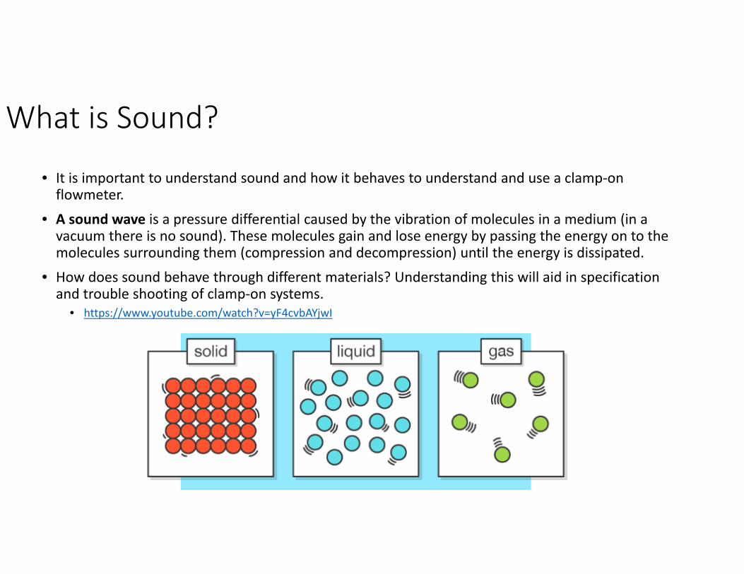
• It is important to understand sound and how it behaves to understand and use a clamp‐on flowmeter.
• A sound wave is a pressure differential caused by the vibration of molecules in a medium (in a vacuum there is no sound). These molecules gain and lose energy by passing the energy on to the molecules surrounding them (compression and decompression) until the energy is dissipated.
• How does sound behave through different materials? Understanding this will aid in specification and trouble shooting of clamp‐on systems.
• https://www.youtube.com/watch?v=yF4cvbAYjwI

Application Details for Clamp‐on Meters• Details you need to know/provide for your application.
• Liquid or Gas name and description and composition• % solids or gas entrained in the liquid if possible; particle size• If non‐standard fluid then provide viscosity and specific gravity at the process temp
• Pipe Material and Schedule/ Class• The pipe wall acts as an amplifier for the transducers; having the correct material and wall thickness is critical for a successful application. Transducer selection is based on pipe material and wall thickness.
• Pipe liner information if applicable; The liner adds to the wall thickness and must be taken into account for sensor selection
• Process pressure for gas models (see next slide)?• Straight run available for the installation?
• In general Liquid meters require 10U and 5D while gas require 20U and 10D to achieve fully developed flow profile
• Area approvals required?• What cable lengths are required?• What power is available?
• More information will be asked but this is the basic information required

Minimum Pressure Guidelines
• For Liquid meters we don’t have any pressure requirements.
• Unlike liquid meters, Gas clamp‐on meters require a minimum pressure inside the pipe to perform to specification.
• This is because the gas molecules are not as tightly packed as a liquid.
• The table to the right shows the min pressure per pipe size and the recommended sensors
• As a rule of thumb we like to tell customers a minimum 150 psig

JFK to SFO Elapsed Time 6:13
SFO to JFK Elapsed Time 5:12
Modes of Operation: Transit Time• Imagine a plane flying with the jet stream. Now
imagine a plane flying against the jet stream.
• If you compare travel times, you will find that the plane going with the jet stream will have a lesser travel time than the plane against (all other variables considered equal).
• Transit time flowmeters essentially function in the same manner comparing the 2 sound signals, timing the time of flight, performing some math internally and determining the fluid velocity.
• As we can see in this example the time differential between the 2 planes travel in opposite directions is about 1 hr.
• From this we can deduce the speed of the jet stream and its direction of flow.

Modes of Operation: Transit Time
• Transit time flowmeters essentially function in the same manner as the previous illustration. On the process pipe we have ultrasonic transducers that are delivering sound energy to the process fluid.
• These same transducers are also listening for the signal from its partner transducer. This process occurs very quickly. Ping then listen.
• Transit Time ultrasonic flow measurement measures the time it takes a signal to go from a sensor 1 to sensor 2. Then sensor 2 to sensor 1, and uses the difference in transit time to calculate the velocity and volumetric flowrate.
https://youtu.be/DD2bBLu6kLM?end=93
Flow(Vf)
UpstreamBeam
Downstrea
mBeam Down
Up
ID
REFLECT MOUNT
DIRECT MOUNT

General Installation Guidelines for TT Liquids Flowmeter• Minimum measuring range: 0.3 to 12m/s (30 m/s for high precision sensors)
• Pipe must be completely full within the sensor installation volume for accurate flow measurement (All flowmeters assume a full pipe)!
• Typical MINIMUM straight pipe requirements are: 10 diameters upstream/5 diameters downstream. Additional straight run is required for any pipe anomaly.
• Sensors should be installed at least 20° off vertical for horizontal pipes. This reduces the chance of beam interference from gas buildup at the top of the pipe
• Operation inside the Reynolds transition region; 1000 < Re < 5000, should be avoided for best accuracy
• Ultrasonic coupling compound is provided with all sensor orders. Insure that a permanent coupling compound is used for long term installations
• Process fluid should have a maximum of 15% Suspended solids or entrained gas.
• NOTE: ALL CLAMP‐ON APPLICATIONS REQUIRE A COMPLETED APPLICATION DATASHEET FOR SIEMENS

Modes of Operation: Doppler• We have all heard the term Doppler Radar on the weather channel.• Doppler shift ‐ a phenomenon, observed for sound waves and electromagnetic radiation, characterized by a change in the apparent frequency of a wave, as a result of relative motion between the observer and the source.
• https://www.youtube.com/watch?v=h4OnBYrbCjY

Modes of Operation: Doppler• Doppler operation is used in applications where conditions interrupt transit time monitoring.
• Example high solids content or high aeration (attenuates sound energy)
• There must be reflective particulate in the flow stream; these reflectors may be comprised of solid particles or air (gas) bubbles.
• The particulates often require a certain concentration and size
• Minimum 50 ppm concentration (gas or Solids)• Minimum 150 microns or larger
• When the sound energy reflects off the particles the frequency of the sound wave shifts and this is interpreted to estimate the flow velocity
• https://youtu.be/DD2bBLu6kLM?start=139&end=162

Modes of Operation: Doppler• Due to the varying velocities of the particles in the flow stream, a wide spectrum of return frequencies will be returned to the sensor
• A weighted average of these frequencies is calculated to determine the flow velocity.
• Some examples are slurries, Wastewater treatment, paper pulp
• On very large pipes multiple pairs of Doppler sensors can be connected in parallel for better flow averaging.
• Due to the nature of applications where Doppler is used (E.G. aerated), the technology is inherently less accurate than transit time. Typical expected performance is 3‐5% accuracy.
Pipe WallProcess FluidParticles

Transit Time: Transducer Mounting • Transit time operation can be done in either “reflect mount” or “direct mount” transducer/pipe configurations.
• “Reflect Mount” is generally used on metallic pipes.
• “Direct Mount” is generally used on plastic pipes. Because the pipe walls do not allow for a powerful reflection of the sound.
Reflect Mount
Direct Mount

• Multiple transducer pairs can be used on a single pipe.
• This is referred to as “multi‐path” and provides more samples from the same point.
• The flowmeter the averages these multiple samples to get a more accurate flow measurement.
• Greater cross sectional averaging• Improved accuracy• Improved repeatability• Redundancy• Reduces error due to asymmetrical flow profile AKA limited straight run or anomalies
• https://youtu.be/DD2bBLu6kLM?start=123&end=139
Transit Time: Transducer Mounting

Doppler: Transducer Mounting
Doppler
Transit Time
191N/P Sensors 1011 Universal – C3 Sensors
• Doppler functionality is not currently available with the new Siemens models (2020) but is expected to be re‐developed in 2023.
• Doppler sensors are oriented in a side by side fashion for the 191N/P Sensors and in‐line fashion with the 1011 C3 transducers.
• Transducer A (upstream) acts as the transmitter and Transducer B(downstream) acts as the receiver. This is different from transit time were both act as transmitter and receiver.

Review Questions
• A person wants to use a clamp‐on flow meter for clean water. What technology should be used?
• A person wants to use a clamp‐on flow meter for raw sewage which has a suspended solids content of 25%. What technology should be used?

Pipe Anomalies • Every flowmeter has a straight run requirement that is stated in the flowmeter datasheet commonly stated in pipe diameters. The flowmeter assumes a fully developed flow profile.
• A straight run of 10 up and 5 down is commonly suggested.
• Not all applications have the appropriate straight run available. An anomaly is a section of piping that prevents a fully developed flow profile from occurring
• Piping anomalies can include elbows, valves, pumps, tees etc.
• https://www.youtube.com/watch?v=DSYE9jqQScM
• With Siemens FS220 /230 Clamp‐on we can combat these anomalies by telling the flow meter what to expect and it can apply algorithms to combat the poor flow profile.

Combating Pipe Anomalies• All Siemens Clamp‐on meters have the ability to correct for the theoretical flow profile based on actual piping. FS220 and FS230 can correct for upstream and downstream with the use of the on‐board Pipe Configuration Menu Tool.
• This gives a more accurate measurement in less than ideal conditions.
• Again we can also use multiple transducer sets (multi‐path) to take an average reading of the pipe to better determine true flow.
• Remember that a magnetic flowmeter also takes an average of the complete pipe diameter.

Siemens Wide Beam Technology• Throughout some of the Siemens videos and literature you will hear the term “Wide Beam Technology”. What is this and what does it do for the customer?
• This technology is referring to Siemens High Precision Sensors only.
• Siemens is a pioneer in the use of Lamb wave transit‐time sensors for clamp‐on flow measurement.
• WideBeam® technology uses the pipe wall as a waveguide to optimize the signal‐to‐noise ratio and provide a wider area of vibration. This makes this kind of sensor less sensitive to any change in the fluid medium.
• These means the Transducer is able to utilize the natural resonance frequency of the pipe wall to amplify the signal.

Sizing a Siemens Clamp‐on Meter• To size a Siemens meter we use a tool called Si‐ware.
• For older meters Si‐ware was an in depth tool that allowed you to see how your meter was performing; Some features are now available internal to the new FS230 and 220 Models.
• Currently Si‐ware is used with the new meters purely to size the transducers.
• Transducer selection is based on the pipe material and pipe wall thickness.
• The Si‐ware tool will calculate some important information that is worth noting before installation.
• Estimated Speed of Sound (good to know and compare to your actual V/S after installation to validate performance)
• Recommended Transducer Spacing• Recommended Mounting Config
Estimated V/S
Recommended Transducer andMounting
Pipe Info
User Selected Units

Si‐Ware Serial Communication SoftwareSi‐Ware Benefits• Serial communications• Instant status summary• Signal & flow graphs• Detailed diagnostics• Sensor selection• AGA-8 computation & uploads• System status report generator• Software flash-loads• Site backup

• SIMATIC PDM – Process Device Manager • The Universal Tool for Engineering and Commissioning
• Standard connector and protocol (USB 2.0)
• PDM BENEFITS• Easy access• Commissioning• Service and diagnostics without disturbing communication
• Parameterization• Diagnostics • Device management
PDM has more than 5,000 devices from over200 manufacturers in it’s device library
SIMATIC PDM via USB Interface

Simulator – PC based Local user interface• SIEMENS also has a PC simulator so you can run through programming
the unit before heading into the field
• PC based “LUI” Simulator Software Tool
• Duplicates full transmitter program menu
• Full programming experience for familiarization with menu training
• Simplifies support and assistance
• Allows for program testing without the need of a transmitter/sensors
https://www.youtube.com/watch?v=8l5YWH4aDK0&t=
https://www.youtube.com/watch?v=2rw‐NS1ZjQ4
https://www.youtube.com/watch?v=Y7pBrNfm4So
Configuration Using Simulator Videos:

Sizing a Siemens Clamp‐on Meter• The new FS230 will calculate this information after you punch the variables in. See configuration video later in this presentation.
• Video covering Si‐ware usage for old FUS/FUH/FUG/FUP Meter ‐https://www.youtube.com/watch?v=GdJ0iaR8fQU&t=291s

FS230 Meter Installation and Configuration• Mounting and Connecting FS230
• https://www.youtube.com/watch?v=IaH73tiEBI8&list=PL6BFD6BF929810972&index=55&t=0s
• FS230 Conduit Installation• https://www.youtube.com/watch?v=nwXpbJbTyxs&list=PL6BFD6BF929810972&index=55
• Configuration of FS220 and 230 • https://www.youtube.com/watch?v=VH68BPEeLZc&t=17s

Legacy Flowmeter Installation & Configuration
• FUS Installation and Configuration• https://www.youtube.com/watch?v=X7cGn1Mrdwc&t=2s
• FUG Installation and Configuration• https://www.youtube.com/watch?v=0N200rWixB4
• FUG Part 2 Gas Compensation• https://www.youtube.com/watch?v=EC5‐I9UnLoo
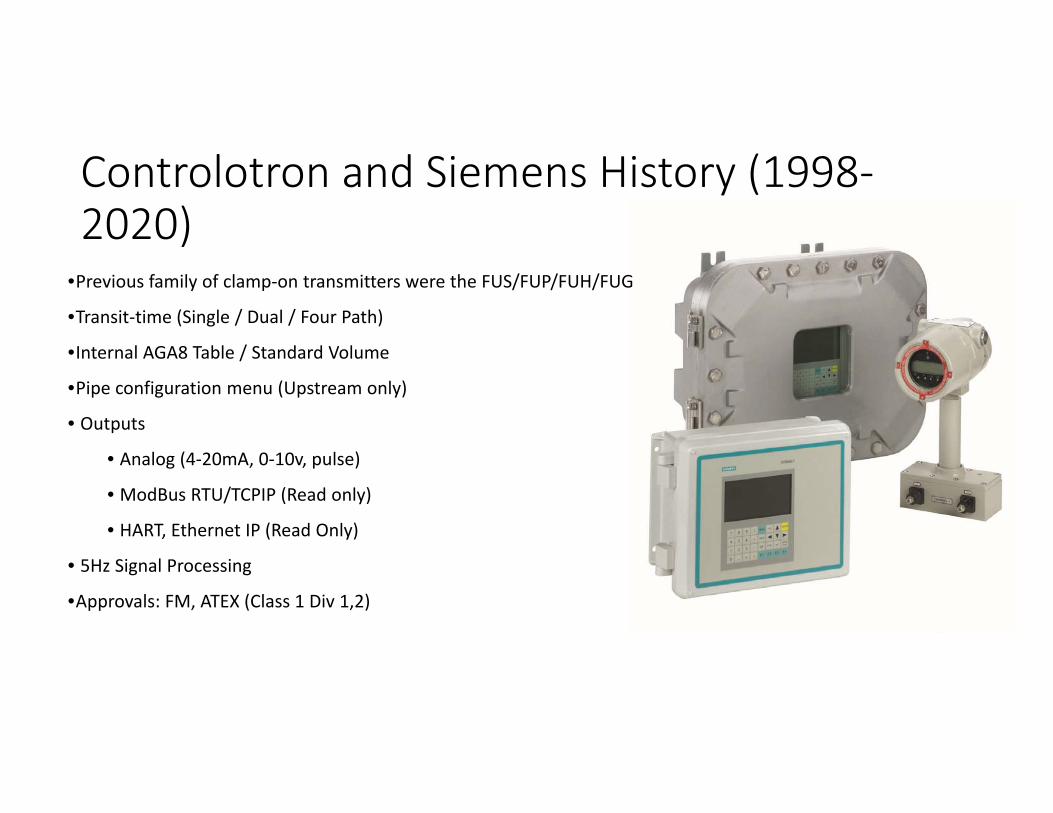
Controlotron and Siemens History (1998‐2020)
•Previous family of clamp‐on transmitters were the FUS/FUP/FUH/FUG
•Transit‐time (Single / Dual / Four Path)
•Internal AGA8 Table / Standard Volume
•Pipe configuration menu (Upstream only)
• Outputs
• Analog (4‐20mA, 0‐10v, pulse)
• ModBus RTU/TCPIP (Read only)
• HART, Ethernet IP (Read Only)
• 5Hz Signal Processing
•Approvals: FM, ATEX (Class 1 Div 1,2)

Siemens NEW FS220 Basic Model
FS220
• FS220 (Basic Applications)• Based on the same digitalized platform as the FST030 this system provides the
same accuracy and similar functions on a lower cost level. This system is ideal for water. measurement and any application not requiring temperature or viscosity compensation.
• 4 push buttons mimicking the HydroRanger 200 HMI housing makes configuration simple.
• NEMA 4X general purpose enclosure.• Pipe sizes from 0.5 inch to 360 inch; Pipe wall thickness from 1 to 35 mm; specials
on request up to 65 mm; Single Path only.• Pipe materials: ideal for all metals, glass, FRP and most PVC variants; NOT for
concrete pipes and special compound pipes.• Media temperatures from ‐40 to 121 °C; universal high temperature sensors for
up to 230 °C max.• Underground/submerged locations, non‐ideal environments, strong pipe
vibrations.• Does not allow external inputs for temp and pressure compensation.• 100HZ update rate; Fast response

Siemens NEW FS230 Basic‐Advanced Model
• FS230 (Basic to Advanced Applications)• Pipes Sizes 0.5 to 394 inches; Available in General Liquid, Hydrocarbon, and Gas Models• Digital Platform – Flow meter technologies share a common platform• DSL – Digital Sensor Link – Digitizes the ultrasonic signal at the earliest stage of measurement for a strong SNR
• Wall‐mount enclosure, 1 or 2 path• Enclosure material: Aluminum, Rating: IP66/67, NEMA 4X• Approvals: FM, FMc, ATEX, IECEx• Up to 6 I/O channels combining analog, relay or digital outputs & binary input + RTD
• Fully graphical display, 240 x 160 pixels• 24 to 90 V DC, 100 to 240 V AC (universal power supply / Fuse: 500mA,250V)• W/ internal DSL (Digital up to dual path; With External DSL
FS230

Siemens NEW FS230 for Hydrocarbons• The FS230 can be used to measure the flow of hydrocarbon liquids in a pipeline. Crude Oil, Refined Petroleum, Liquified Gasses etc.
• Applications for the Hydrocarbon Model include check metering, allocation, flow survey verification, production and storage.
• The hydrocarbon model is able to compute many other process variable than the standard model including: Standard volume or mass flow, specific gravity, standard density, standard SG, standardizing factor, liquident, API gravity, standard kinematic viscosity, interface detection and liquid identifier
• When quoting a Hydrocarbon model it is recommended to include dual path unit with an RTD for temperature compensation, and IO cards for multiple 4‐20 mA outputs and a relay board. If the application deems necessary we can provide a pressure transmitter for pressure compensation (4‐20 ma input on the FS230).
• Watch video below
https://new.siemens.com/us/en/products/automation/process‐instrumentation/flow‐measurement/ultrasonic/clamp‐on/sitrans‐fs230.html

Page 36
FS230 System variants
Wall mount FST030 w. integrated DSLStandard (Water), Oil or GasEX: FM, ATEX, IECEx
Wall mount FST030 w. external DSLStandard (Water), Oil or GasEX: FM, ATEX, IECEx
Industrial FST030 with external DSLStandard (Water), Oil or GasEX: FM, ATEX, IECEx***Available 2021
Ext. DSL ‐ recommendation for Ex‐application
Siemens NEW FS230 Basic‐Advanced Model

• Transmitter w/internal DSL supports 1‐2 path (2 sensor pairs on one or two pipe)
• Firmware versions: Standard‐Liquid, Hydrocarbon, Gas• Standardized menu navigation across digital platform; touch through glass• Real 100Hz – signal processing; Much faster than previous models. Almost as fast as a mag meter.
• HART or Modbus outputs• Transmitter w/ External Digital Sensor Link up to 4‐Path (4 sensor pairs on 1 or 2 pipes)
• External Digital Sensor Link allows a short cable run from the transducers to the DSL; Then from the SAL to the Wall Mount Enclosure we can have a single DSL cable run up to 150m. Without DSL we are limited to 66ft transducer cables.
• Flow Sonic Sensor Family – FSS200 (Clamp‐On Transducer)• Gas & Liquid transducers are the same
External DSL Module
Page 37
Siemens NEW FS230 Basic‐Advanced Model

Page 38
• Wall housing painted aluminum die‐cast,
Lid removable, IP 66/67, ‐40°C up to +60°C
• F‐Connector Tool – Used for connecting the sensor cables
• Lining hard foam
• HMI Display with 4 key pad
• Power supply Cover with terminal compartment
• Internal DSL‐Module (up to dual‐path)
• Terminal compartment I/O – Channel 1, 2, 3 and 4
• DSL‐analog in channel 5 & 6 – Temperature by RTD
• Cable entry 9 x M20x1,5
Siemens NEW FS230 Modular Design

• USB interface
• Power‐Supply module 100‐ 240 VAC, 47‐63 Hz
20‐27V DC ‐ 20VA
• HMI module (HART or Modbus) with 4GB‐SD
• I/O‐module channel 1 ‐ 4; 4‐20mA/frequency or relay
• Barrier‐module with internal Modbus‐connection to DSL
• Internal DSL‐Module – either Liquid or GAS with Input
Channel 5 & 6 (Analog / PT100, 500, 1000)
• All function modules plug‐in and Field Replaceable
• Fixed with hard foam cover that makes for easy servicing
Siemens NEW FS230 Modular Design

Page 40
FST030 – Power Supply Module
• Power supply module
• for wall mount – enclosure
• Multi function for DC and AC power
• 100‐ 240 VAC, 47‐63 Hz ‐ 20‐27V DC ‐ 20VA
• ‐40F up to 140F (Transmitter ambient)
• Spare part: A5E38263021
Siemens NEW FS230 Modular Design
Page 41
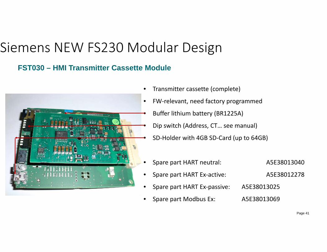
FST030 – HMI Transmitter Cassette Module
• Transmitter cassette (complete)
• FW‐relevant, need factory programmed
• Buffer lithium battery (BR1225A)
• Dip switch (Address, CT… see manual)
• SD‐Holder with 4GB SD‐Card (up to 64GB)
• Spare part HART neutral: A5E38013040
• Spare part HART Ex‐active: A5E38012278
• Spare part HART Ex‐passive: A5E38013025
• Spare part Modbus Ex: A5E38013069
Siemens NEW FS230 Modular Design

Page 42
FST030 – I/O Cassette Module• IO modules are easily installed or replaced
• Same design as Coriolis FCT030
• In‐/Output cassette (Channel 1 ‐ 4)
• 22 variants, factory assembled
• Non Ex: variable active / passive
• Ex: either active or passive (NOT switchable)
• Channel 1: HART, neutral, Ex a or Ex p, Modbus
• Channel 2: Analog (4‐20 mA, Frequency, Puls)
• Channel 3: options ‐ None, Analog, Relay
• Channel 4: options ‐ None, Analog, Relay
• Spare part: see catalog
Siemens NEW FS230 Modular Design

Page 43
FST030 – Sensor input cassette module
• Sensor input cassette
• Two functions:
• Sensor modbus communication to DSL (up to 150m)
• Acts as the barrier module (even for non Ex)
• Actual two variants, for internal, for external DSL
• Spare part: N/A
Siemens NEW FS230 Modular Design

Page 44
FST030 – HMI Display and Keypad Module
• HMI ‐ Human machine interface for wall mount
• Display 240 x 160 pixel, backlight
• Keypad – 4 arrow key for menu navigation
• Spare part: A5E37697615
Siemens NEW FS230 Modular Design
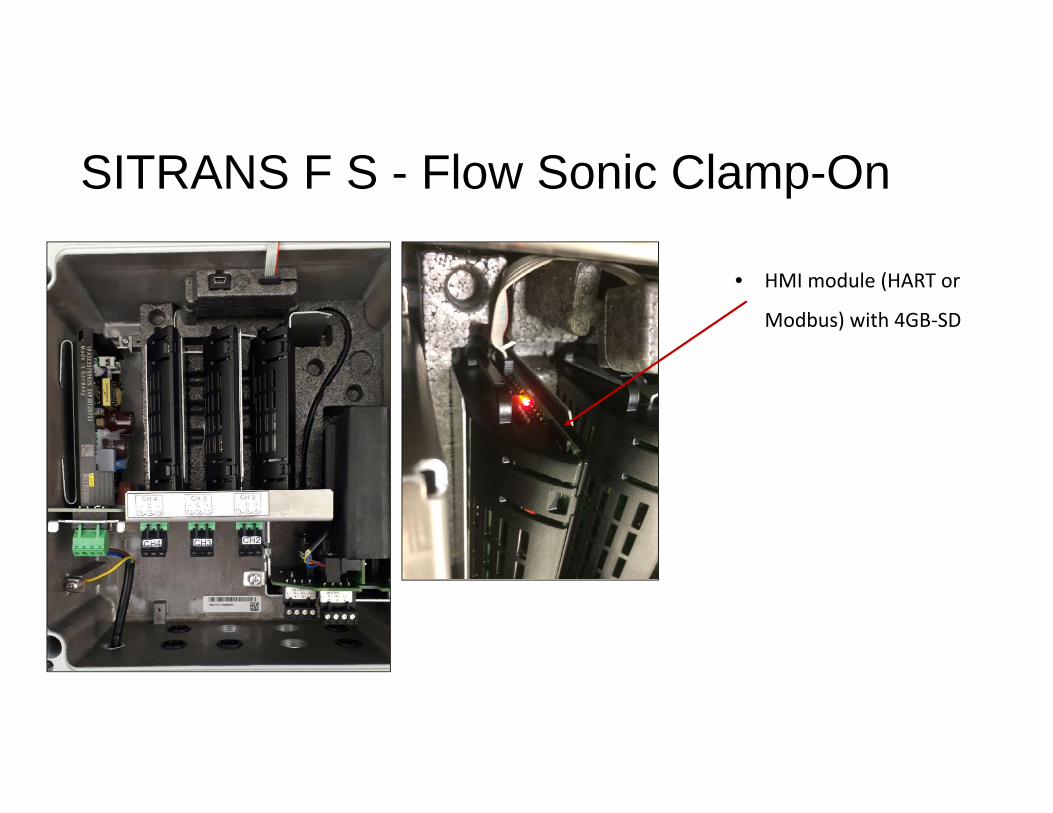
SITRANS F S - Flow Sonic Clamp-On
• HMI module (HART or
Modbus) with 4GB‐SD

Modular Design
• The point of the previous slides is to showcase the modular design of the FS230 which makes field repairs/ upgrades simple.

Soundwater Technologies ORCAS• Soundwater Tech makes several ultrasonic meters from portable to permanent to semi permanent.
• All the flowmeters use the ORCAS phone app and Bluetooth for device configuration, datalogging, and interaction.

Soundwater Technologies ORCAS Kits• ORCAS is a portable ultrasonic flow meter designed for ease of use and speed.
• Individual models cover 1‐20 Inch pipe size.
• 15 upstream and 5 downstream straight run required.
• Pipe materials include Metal: Steel, Stainless Steel, Copper, Brass, Aluminum; Plastic: PVC, CPVC, HDPE, LDPE, PE, PIP, FRP
• +/‐ 1‐2% accuracy for pipe below 1.5 inch and +/‐ 2‐3% above 1.5 inch
• Contains a rechargeable battery for 12+ hours of run time; can be plugged in for longer datalogging sessions
• All kits come with coupling gel, wall charger, flowmeter (includes transducers, frame, straps).
• Transit Time only
https://www.youtube.com/watch?v=yZzsJblarfA
https://www.youtube.com/watch?v=4c7QZwSAwIQ&t


Soundwater Technologies Cypress• The Cypress flowmeter adds to the ORCAS in that it can connect to the PLC or SCADA system with s 4‐20 mA, pulse, or modbus RS485 signal and external power for long‐term use.
• Has an std M12 quick disconnect connector to connect another device and 24VDC Power.
• Bluetooth and mobile device are still used to configure the flowmeter.
• The Cypress comes with metal pipe bands rather than the rubber straps the ORCAS shows.
• Individual models can cover pipe sizes 1 to 36 Inches.
• Transit Time Only
• Pipe Materials Metal: Steel, Stainless Steel, Copper, Brass, Aluminum, Ductile Iron Plastic: PVC, CPVC, HDPE, LDPE, PE, PIP, FRP
https://static1.squarespace.com/static/5d682657f391f10001c371b5/t/5e2c868bd455646409da82d6/1579976336237/Cypress+Quick+Start+Guide+200124.pdf


Soundwater Technologies Comano• A permanently installed ultrasonic flowmeter• Wall mount touch screen display separate from the transducer assembly; Connects to SCADA or PLC with 4‐20mA, Pulse, Modbus RS485, and alarm outputs
• NOTE: The isolation for all outputs is as a group; that is, all of the outputs share a common reference
• 10 Pin M12 Cables are used to connect flowmeter to display and display to PLC/ SCADA
• Good for submersible applications• Android‐based touchscreen user interface; backlit; Metric and English units
https://static1.squarespace.com/static/5d682657f391f10001c371b5/t/5e2c8782d455646409dab348/1579976582379/Camano+CM+Quick+Start+200124.pdf

Review Questions??1. List all the components that make up a clamp‐on flow meter system for water (no temp or pressure compensation)2. What is a good indicator of flow sensor performance? How will you know what value this should be?3. A customer wants to get a quote for a clamp on meter. What information do you need to get from them to quote a
product?4. A customer wants to install a flow meter for a 48 Inch carbon steel pipe.
1. Come up with 2 reasons they should consider a clamp‐on meter.2. Come up with 2 reason they may want to use a inline mag meter.
5. A flow meter is to be used to measure clean city water. Should we select transit time or doppler sensors? 6. The previous application does not have adequate straight run but the customer wants top accuracy. What can we
do?7. For influent sewage (with a suspended solids content above 20%) should you use Doppler or Transit time? 8. For activated Sludge should you use a Doppler or Transit Time? 9. Quote a FS230 Hydrocarbon model for a 16 Inch SCH80 Pipe, 2000‐10000 GPM of liquid Hexane. C1D2 Approvals
required. Print your Si‐ware report and review with someone in applications.10. A customers application calls for a low cost clamp‐on flowmeter for chilled water in a 6 inch sch 40 carbon steel
pipe. Output requirements are a 4‐20 mA signal for flow rate. What model from Siemens and transducer pair would you quote? Create a P/N on PIA.
11. Can a clamp‐on be used for gas flow measurement with 5 PSIG pressure in the pipe?12. Generate a Siware report for 2 inch PVC pipe. Set the FS230 demo up on 2 inch pipe in the flow lab. Compare the
speed of sound and other parameters from Siware with those on the FS230.13. Set up the ORCAS demo in the flow lab.