
GE Sensing & Inspection Technologies Transport ® PT878 Portable Liquid Ultrasonic Flowmeter
97
GE Sensing & Inspection Technologies Transport ® PT878 Portable Liquid Ultrasonic Flowmeter Abridged Manual
Transcript of GE Sensing & Inspection Technologies Transport ® PT878 Portable Liquid Ultrasonic Flowmeter

GESensing & Inspection Technologies
Transport® PT878Portable Liquid Ultrasonic Flowmeter
Abridged Manual

GESensing & Inspection Technologies
Transport® PT878Portable Liquid Ultrasonic Flowmeter
Abridged Manual914-219EAugust 2008

August 2008
Warranty Each instrument manufactured by GE Sensing is warranted to be free from defects in material and workmanship. Liability under this warranty is limited to restoring the instrument to normal operation or replacing the instrument, at the sole discretion of GE Sensing. Fuses and batteries are specifically excluded from any liability. This warranty is effective from the date of delivery to the original purchaser. If GE Sensing determines that the equipment was defective, the warranty period is:
• one year for general electronic failures of the instrument
• one year for mechanical failures of the sensor
If GE Sensing determines that the equipment was damaged by misuse, improper installation, the use of unauthorized replacement parts, or operating conditions outside the guidelines specified by GE Sensing, the repairs are not covered under this warranty.
The warranties set forth herein are exclusive and are in lieu ofall other warranties whether statutory, express or implied(including warranties of merchantability and fitness for aparticular purpose, and warranties arising from course ofdealing or usage or trade).
iii

August 2008
Return Policy If a GE Sensing instrument malfunctions within the warranty period, the following procedure must be completed:
1. Notify GE Sensing, giving full details of the problem, and provide the model number and serial number of the instrument. If the nature of the problem indicates the need for factory service, GE Sensing will issue a RETURN AUTHORIZATION number (RA), and shipping instructions for the return of the instrument to a service center will be provided.
2. If GE Sensing instructs you to send your instrument to a service center, it must be shipped prepaid to the authorized repair station indicated in the shipping instructions.
3. Upon receipt, GE Sensing will evaluate the instrument to determine the cause of the malfunction.
Then, one of the following courses of action will then be taken:
• If the damage is covered under the terms of the warranty, the instrument will be repaired at no cost to the owner and returned.
• If GE Sensing determines that the damage is not covered under the terms of the warranty, or if the warranty has expired, an estimate for the cost of the repairs at standard rates will be provided. Upon receipt of the owner’s approval to proceed, the instrument will be repaired and returned.
iv

August 2008
Table of Contents
Chapter 1: Installation & Operation
Introduction . . . . . . . . . . . . . . . . . . . . . . . . . . . . . . . . . . . . . . . . . . . . . . . . . . . . . . . . . . . . . . . . . . . . . . . . . . . . . . . 1-1The Flowcell . . . . . . . . . . . . . . . . . . . . . . . . . . . . . . . . . . . . . . . . . . . . . . . . . . . . . . . . . . . . . . . . . . . . . . . . . . . . . . . 1-1Making Electrical Connections . . . . . . . . . . . . . . . . . . . . . . . . . . . . . . . . . . . . . . . . . . . . . . . . . . . . . . . . . . . . . . 1-2
Power Connection . . . . . . . . . . . . . . . . . . . . . . . . . . . . . . . . . . . . . . . . . . . . . . . . . . . . . . . . . . . . . . . . . . . . . . 1-3Transducer Connections . . . . . . . . . . . . . . . . . . . . . . . . . . . . . . . . . . . . . . . . . . . . . . . . . . . . . . . . . . . . . . . . 1-3Input/Output Connections . . . . . . . . . . . . . . . . . . . . . . . . . . . . . . . . . . . . . . . . . . . . . . . . . . . . . . . . . . . . . . 1-3The Infrared Interface . . . . . . . . . . . . . . . . . . . . . . . . . . . . . . . . . . . . . . . . . . . . . . . . . . . . . . . . . . . . . . . . . . 1-4
Caring for the PT878 Batteries . . . . . . . . . . . . . . . . . . . . . . . . . . . . . . . . . . . . . . . . . . . . . . . . . . . . . . . . . . . . . . 1-4Charging the Batteries. . . . . . . . . . . . . . . . . . . . . . . . . . . . . . . . . . . . . . . . . . . . . . . . . . . . . . . . . . . . . . . . . . 1-4Storing the Batteries. . . . . . . . . . . . . . . . . . . . . . . . . . . . . . . . . . . . . . . . . . . . . . . . . . . . . . . . . . . . . . . . . . . . 1-5Replacing the Batteries . . . . . . . . . . . . . . . . . . . . . . . . . . . . . . . . . . . . . . . . . . . . . . . . . . . . . . . . . . . . . . . . . 1-6
Powering ON and OFF . . . . . . . . . . . . . . . . . . . . . . . . . . . . . . . . . . . . . . . . . . . . . . . . . . . . . . . . . . . . . . . . . . . . . . 1-7Using the Screen and Keypad. . . . . . . . . . . . . . . . . . . . . . . . . . . . . . . . . . . . . . . . . . . . . . . . . . . . . . . . . . . . . . . 1-9
The Screen . . . . . . . . . . . . . . . . . . . . . . . . . . . . . . . . . . . . . . . . . . . . . . . . . . . . . . . . . . . . . . . . . . . . . . . . . . . . . 1-9The Keypad . . . . . . . . . . . . . . . . . . . . . . . . . . . . . . . . . . . . . . . . . . . . . . . . . . . . . . . . . . . . . . . . . . . . . . . . . . . 1-11
Chapter 2: Initial Setup
Introduction . . . . . . . . . . . . . . . . . . . . . . . . . . . . . . . . . . . . . . . . . . . . . . . . . . . . . . . . . . . . . . . . . . . . . . . . . . . . . . . 2-1Entering the Program Menu . . . . . . . . . . . . . . . . . . . . . . . . . . . . . . . . . . . . . . . . . . . . . . . . . . . . . . . . . . . . . . . . 2-1Entering the Transducer Parameters . . . . . . . . . . . . . . . . . . . . . . . . . . . . . . . . . . . . . . . . . . . . . . . . . . . . . . . . 2-2
Special Transducers . . . . . . . . . . . . . . . . . . . . . . . . . . . . . . . . . . . . . . . . . . . . . . . . . . . . . . . . . . . . . . . . . . . . 2-3Entering the Pipe Parameters . . . . . . . . . . . . . . . . . . . . . . . . . . . . . . . . . . . . . . . . . . . . . . . . . . . . . . . . . . . . . . . 2-4Entering the Pipe Lining Parameters . . . . . . . . . . . . . . . . . . . . . . . . . . . . . . . . . . . . . . . . . . . . . . . . . . . . . . . . 2-6Entering the Fluid Parameters . . . . . . . . . . . . . . . . . . . . . . . . . . . . . . . . . . . . . . . . . . . . . . . . . . . . . . . . . . . . . . 2-7Entering the Signal Path Parameters . . . . . . . . . . . . . . . . . . . . . . . . . . . . . . . . . . . . . . . . . . . . . . . . . . . . . . . . 2-8
Clamp-On Transducers . . . . . . . . . . . . . . . . . . . . . . . . . . . . . . . . . . . . . . . . . . . . . . . . . . . . . . . . . . . . . . . . . 2-9Wetted Transducers . . . . . . . . . . . . . . . . . . . . . . . . . . . . . . . . . . . . . . . . . . . . . . . . . . . . . . . . . . . . . . . . . . . . 2-9
Entering Correction Factors. . . . . . . . . . . . . . . . . . . . . . . . . . . . . . . . . . . . . . . . . . . . . . . . . . . . . . . . . . . . . . . . 2-10Entering Reynolds Correction Data . . . . . . . . . . . . . . . . . . . . . . . . . . . . . . . . . . . . . . . . . . . . . . . . . . . . . 2-10Entering a Calibration Factor. . . . . . . . . . . . . . . . . . . . . . . . . . . . . . . . . . . . . . . . . . . . . . . . . . . . . . . . . . . 2-11
v

August 2008
Table of Contents (cont.)
Chapter 3: Operation
Configuring The Display Options . . . . . . . . . . . . . . . . . . . . . . . . . . . . . . . . . . . . . . . . . . . . . . . . . . . . . . . . . . . . 3-1The Format Option . . . . . . . . . . . . . . . . . . . . . . . . . . . . . . . . . . . . . . . . . . . . . . . . . . . . . . . . . . . . . . . . . . . . . 3-2The View Option. . . . . . . . . . . . . . . . . . . . . . . . . . . . . . . . . . . . . . . . . . . . . . . . . . . . . . . . . . . . . . . . . . . . . . . . 3-3The Limits Option. . . . . . . . . . . . . . . . . . . . . . . . . . . . . . . . . . . . . . . . . . . . . . . . . . . . . . . . . . . . . . . . . . . . . . . 3-4The Measurement Option. . . . . . . . . . . . . . . . . . . . . . . . . . . . . . . . . . . . . . . . . . . . . . . . . . . . . . . . . . . . . . . 3-6
Customizing the Display Screen. . . . . . . . . . . . . . . . . . . . . . . . . . . . . . . . . . . . . . . . . . . . . . . . . . . . . . . . . . . . . 3-7Specifying the Number of Displayed Parameters. . . . . . . . . . . . . . . . . . . . . . . . . . . . . . . . . . . . . . . . . 3-8Customizing the Softkeys . . . . . . . . . . . . . . . . . . . . . . . . . . . . . . . . . . . . . . . . . . . . . . . . . . . . . . . . . . . . . . . 3-9
Error Messages . . . . . . . . . . . . . . . . . . . . . . . . . . . . . . . . . . . . . . . . . . . . . . . . . . . . . . . . . . . . . . . . . . . . . . . . . . . 3-12Programming Global Meter Settings . . . . . . . . . . . . . . . . . . . . . . . . . . . . . . . . . . . . . . . . . . . . . . . . . . . . . . . 3-13
The Units Option . . . . . . . . . . . . . . . . . . . . . . . . . . . . . . . . . . . . . . . . . . . . . . . . . . . . . . . . . . . . . . . . . . . . . . 3-14The Battery Charger Option. . . . . . . . . . . . . . . . . . . . . . . . . . . . . . . . . . . . . . . . . . . . . . . . . . . . . . . . . . . . 3-15The Date/Time Option . . . . . . . . . . . . . . . . . . . . . . . . . . . . . . . . . . . . . . . . . . . . . . . . . . . . . . . . . . . . . . . . . 3-16The Locale Option . . . . . . . . . . . . . . . . . . . . . . . . . . . . . . . . . . . . . . . . . . . . . . . . . . . . . . . . . . . . . . . . . . . . . 3-17The Contrast Option . . . . . . . . . . . . . . . . . . . . . . . . . . . . . . . . . . . . . . . . . . . . . . . . . . . . . . . . . . . . . . . . . . . 3-19The Backlight Option . . . . . . . . . . . . . . . . . . . . . . . . . . . . . . . . . . . . . . . . . . . . . . . . . . . . . . . . . . . . . . . . . . 3-20The Language Option . . . . . . . . . . . . . . . . . . . . . . . . . . . . . . . . . . . . . . . . . . . . . . . . . . . . . . . . . . . . . . . . . 3-20The Communications Option. . . . . . . . . . . . . . . . . . . . . . . . . . . . . . . . . . . . . . . . . . . . . . . . . . . . . . . . . . . 3-21The Totals Option . . . . . . . . . . . . . . . . . . . . . . . . . . . . . . . . . . . . . . . . . . . . . . . . . . . . . . . . . . . . . . . . . . . . . 3-23
Chapter 4: Managing Site Files
The Site Menu. . . . . . . . . . . . . . . . . . . . . . . . . . . . . . . . . . . . . . . . . . . . . . . . . . . . . . . . . . . . . . . . . . . . . . . . . . . . . . 4-1The Site Manager Window. . . . . . . . . . . . . . . . . . . . . . . . . . . . . . . . . . . . . . . . . . . . . . . . . . . . . . . . . . . . . . . . . . 4-2The Site Manager Menu . . . . . . . . . . . . . . . . . . . . . . . . . . . . . . . . . . . . . . . . . . . . . . . . . . . . . . . . . . . . . . . . . . . . 4-3
The New Option . . . . . . . . . . . . . . . . . . . . . . . . . . . . . . . . . . . . . . . . . . . . . . . . . . . . . . . . . . . . . . . . . . . . . . . . 4-3The Open Option . . . . . . . . . . . . . . . . . . . . . . . . . . . . . . . . . . . . . . . . . . . . . . . . . . . . . . . . . . . . . . . . . . . . . . . 4-5The Save Option. . . . . . . . . . . . . . . . . . . . . . . . . . . . . . . . . . . . . . . . . . . . . . . . . . . . . . . . . . . . . . . . . . . . . . . . 4-6The Save As Option. . . . . . . . . . . . . . . . . . . . . . . . . . . . . . . . . . . . . . . . . . . . . . . . . . . . . . . . . . . . . . . . . . . . . 4-7The Refresh Option . . . . . . . . . . . . . . . . . . . . . . . . . . . . . . . . . . . . . . . . . . . . . . . . . . . . . . . . . . . . . . . . . . . . . 4-8The Rename Option . . . . . . . . . . . . . . . . . . . . . . . . . . . . . . . . . . . . . . . . . . . . . . . . . . . . . . . . . . . . . . . . . . . . 4-8The Delete Option . . . . . . . . . . . . . . . . . . . . . . . . . . . . . . . . . . . . . . . . . . . . . . . . . . . . . . . . . . . . . . . . . . . . . . 4-9The Message Option. . . . . . . . . . . . . . . . . . . . . . . . . . . . . . . . . . . . . . . . . . . . . . . . . . . . . . . . . . . . . . . . . . . 4-10The Print Option . . . . . . . . . . . . . . . . . . . . . . . . . . . . . . . . . . . . . . . . . . . . . . . . . . . . . . . . . . . . . . . . . . . . . . . 4-12
vi

August 2008
Table of Contents (cont.)
Chapter 5: Data Logging
The Logging Menu . . . . . . . . . . . . . . . . . . . . . . . . . . . . . . . . . . . . . . . . . . . . . . . . . . . . . . . . . . . . . . . . . . . . . . . . . 5-1The Log Manager Window . . . . . . . . . . . . . . . . . . . . . . . . . . . . . . . . . . . . . . . . . . . . . . . . . . . . . . . . . . . . . . . . . . 5-2The Log Manager Menu . . . . . . . . . . . . . . . . . . . . . . . . . . . . . . . . . . . . . . . . . . . . . . . . . . . . . . . . . . . . . . . . . . . . 5-2
The File Menu . . . . . . . . . . . . . . . . . . . . . . . . . . . . . . . . . . . . . . . . . . . . . . . . . . . . . . . . . . . . . . . . . . . . . . . . . . 5-3The Log Menu . . . . . . . . . . . . . . . . . . . . . . . . . . . . . . . . . . . . . . . . . . . . . . . . . . . . . . . . . . . . . . . . . . . . . . . . . 5-10The View Menu . . . . . . . . . . . . . . . . . . . . . . . . . . . . . . . . . . . . . . . . . . . . . . . . . . . . . . . . . . . . . . . . . . . . . . . . 5-13
Appendix A: Menu Maps
vii

Chapter 1

Installation & Operation
Introduction. . . . . . . . . . . . . . . . . . . . . . . . . . . . . . . . . . . . . . . . . . . . . . . . . . . . 1-1
The Flowcell . . . . . . . . . . . . . . . . . . . . . . . . . . . . . . . . . . . . . . . . . . . . . . . . . . . . 1-1
Making Electrical Connections . . . . . . . . . . . . . . . . . . . . . . . . . . . . . . . . . . . 1-2
Charging the Batteries . . . . . . . . . . . . . . . . . . . . . . . . . . . . . . . . . . . . . . . . . . 1-4
Powering ON and OFF . . . . . . . . . . . . . . . . . . . . . . . . . . . . . . . . . . . . . . . . . . . 1-7
Using the Screen and Keypad . . . . . . . . . . . . . . . . . . . . . . . . . . . . . . . . . . . . 1-9

August 2008
Introduction The PT878 is a transit-time flowmeter that combines all the features of a full-size flowmeter with the advantages of a portable instrument:
• measure the flow rate of acoustically-conductive single-phase fluids
• measure flow velocities from ±0.03 to ±12 m/sec
• energy flow rate may be calculated for water, glycol, and water/glycol mixtures
• one linear 0/4-20 mA analog output
• two 4-20 mA analog inputs
• runs on rechargeable or alkaline batteries for up to 10 hours
• LCD display for measurements in numeric and graphical format
• store site data in files
• log over 100,000 flow data points internally
• communicate with a PC via an infrared port
• context-sensitive on-line help
• uses all standard GE Sensing transducers
The Flowcell In addition to the PT878, a complete flowmeter system includes a flowcell. The flowcell is that part of the system that uses ultrasonic pulses to interrogate the flow. It consists of:
• Flowcell Pipe - The flowcell can either be created in the existing piping (for example, by inserting wetted transducers into the pipe, or clamping non-wetted transducers onto the pipe), or inserted as a substitute pipe section (spoolpiece). The flowcell must provide mechanical support for the transducers and assure stable fluid conditions for accurate flow measurement.
• Transducers - The transducers convert electrical energy into ultrasonic pulses when in a transmit cycle, and convert the ultrasonic pulses back to electrical energy when in a receive cycle. In the PT878 system, each transducer acts as both a receiver and transmitter, since a series of ultrasonic pulses are alternately sent upstream and then downstream through the flowcell.
Installation & Operation 1-1
August 2008
Making Electrical Connections
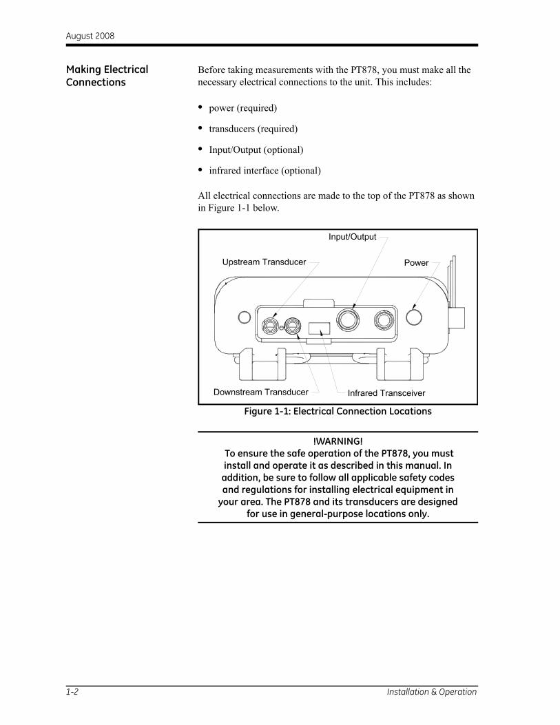
Before taking measurements with the PT878, you must make all the necessary electrical connections to the unit. This includes:
• power (required)
• transducers (required)
• Input/Output (optional)
• infrared interface (optional)
All electrical connections are made to the top of the PT878 as shown in Figure 1-1 below.
Figure 1-1: Electrical Connection Locations
!WARNING! To ensure the safe operation of the PT878, you must install and operate it as described in this manual. In
addition, be sure to follow all applicable safety codes and regulations for installing electrical equipment in
your area. The PT878 and its transducers are designed for use in general-purpose locations only.
Infrared TransceiverDownstream Transducer
Upstream Transducer Power
Input/Output
1-2 Installation & Operation

August 2008
Power Connection The PT878 may be powered by either of the following:
• a 100-120/200-260 VAC wall-mount plug-in module
• 5 internal Cs-size NiCad high-energy rechargeable batteries
• a pack of 3.0 Ahr NiMH batteries
Note: An optional power supplement, part #703-1283, uses 6 AA alkaline batteries.
Regardless of which power option is chosen, you must connect the power cord as shown in Figure 1-1 on the previous page.
IMPORTANT: When you receive the PT878, the batteries are not charged. Therefore, to take measurements on battery power, you must first charge the batteries as described on page 1-5.
Transducer Connections The transducer cables connect to the PT878 with LEMO® coaxial type connectors. Each color-coded cable should have a collar labeled UPSTREAM or DOWNSTREAM. Make transducer cable connections to the top of the flowmeter as shown in Figure 1-1 on the previous page. Because there are various types of transducers and installations, detailed transducer installation is discussed separately in the Liquid Transducer Installation Guide (916-055).
Input/Output Connections The PT878 provides one 0/4-20 mA current output and two 4-20 mA analog inputs with switchable 16V supply for loop- powered temperature transmitters. It also supports digital, frequency, and totalizer outputs. Connect the inputs/outputs using a LEMO®
multi-pin connector as shown in Figure 1-1 on the previous page. The pin numbers for the connector and the color code for the standard input/output cable are shown in Table 1-1 on the next page.
Installation & Operation 1-3

August 2008
Input/Output Connections (cont.)
The Infrared Interface The PT878 comes equipped with an internal infrared transceiver (shown in Figure 1-1 on page 1-2) that enables communication between the meter and other IR devices, particularly the IR ports or dongles (IR to RS232 adapters) of Windows®-based PCs. Users can send and receive site and log data; they can also program the meter via the optional PanaView™ software interface. The PT878 was designed for use with products that comply with the IrDA protocol.
Caring for the PT878 Batteries
The PT878 is equipped with built-in rechargeable batteries to support portable operation. To maintain optimum performance, these batteries require a minimum of maintenance.
Charging the Batteries When you receive the PT878 or if the batteries have not been used for a long period of time, you must charge the batteries before operation. To fully charge the batteries, eight hours is required. When fully-charged, the batteries provide 8 to 10 hours of continuous operation. An internal battery gauge indicates the remaining power in the batteries.
Table 1-1: Cable Assembly for Analog Inputs/OutputsPin # Wire Color Description
1 Black Analog Out 12 Red 16 V (switched)3 White Temperature Transmitter Supply or
Return (Input A)4 Yellow Temperature Transmitter Supply or
Return (Input B)5 Green Analog Ground6 Orange Digital Output (frequency output,
pulse totalizer, diagnostic output or calibration gate)
7 Blue Digital Ground 8 Violet Receive Monitor
1-4 Installation & Operation

August 2008
Charging the Batteries (cont.)
IMPORTANT: To ensure the maximum charge, charge the batteries in an ambient temperature of 50 to 104°F (10 to 40°C).
To charge the batteries, simply plug the AC power module cord into the power jack (shown in Figure 1-1 on page 1-2) and be sure the battery pack is installed. When the PT878 is plugged into line voltage, the internal battery charger automatically charges the batteries, whether the PT878 is ON or OFF. If the PT878 is ON, the Battery icon in the upper right corner of the screen indicates battery status (as shown in Table 1-2 below).
Note: For version 1B of the PT878 software, you must also press the red power key in the upper right corner of the keypad.
Storing the Batteries Always observe the following battery storage temperature ranges:
• 2 days or less: -40 to 158°F (-40 to 70°C)
• less than 1 month: -4 to 131°F (-20 to 55°C)
• more than 1 month: 32 to 104°F (0 to 40°C)
Table 1-2: Battery Status IconsIcon Battery Status
Full battery
Partially full battery
Empty battery
Fully charged battery, connected to AC power
Charging battery
Discharging battery
Failure/missing battery
Notification to check battery
Installation & Operation 1-5

August 2008
Replacing the Batteries !WARNING! Replace batteries only with the specified rechargeable
batteries. The battery charges even when the unit is OFF. Do not attempt to recharge non-rechargeable batteries.
If you need to replace the rechargeable batteries, use the recommended 3.0 Ahr NiMH batteries (part number 200-081). To replace the batteries:
1. Remove the rubber boot.
2. Open the panel located on the back of the PT878 unit.
3. Disconnect the old batteries and dispose of them properly.
4. Install the new batteries (see Figure 1-2 below).
Figure 1-2: Back Panel of PT878
Note: To further extend the battery power of the PT878, the GE Sensing Part #705-1283 option uses 6 AA alkaline batteries.
Battery LocatedBehind Panel
1-6 Installation & Operation

August 2008
Powering ON and OFF Caution!For CE compliance, the PT878 is classified as a battery-powered device, not to be used with the AC adapter. To comply with CE certification, do not operate the meter
with the charger plugged in.
To power the PT878 ON, press the red button in the upper-right-hand corner of the keypad. Immediately upon power up, the PT878 emits a short beep and displays a “PCI Loader” message. It then validates the instrument programming, displays the GE Sensing logo and the software version, and emits a long beep. If the meter fails any of these tests, contact GE Sensing.
!WARNING!If the meter fails the backup battery test, you must send the unit back to the factory for a battery replacement.
After the meter conducts all the self checks, a screen similar to Figure 1-3 below appears.
Figure 1-3: Screen After Powering ON
2000/11/30 09:53 AM
Velocity, ft/s Signal, dB
0.0032
Delta-T, ns
0.10 0.0
Volume, l/s
E0: No Errors
ABC.SIT
Installation & Operation 1-7

August 2008
Powering ON and OFF (cont.)
To turn the PT878 OFF, press the red key and hold it for 3 seconds. The screen now appears similar to Figure 1-4 below.
Figure 1-4: The Shutdown Menu
Three options are now available:
• Press [F1] to shut down the PT878 - This turns it completely OFF.
• Press [F2] to send the PT878 into sleep mode - In this mode, the PT878 remains in a standby mode and you can resume taking measurements immediately by pressing the power button again.
• Press [F3] to cancel the command - This returns the PT878 to normal operation.
Note: If the PT878 locks up, you can reset it by pressing the power key (the red key in the upper right corner) and holding it for 15 seconds.
Velocity, ft/s Signal, dB
Delta-T, ns Volume, l/s
Resume
SHUTDOWN: Meter OFFSLEEP: Meter IdleCANCEL: Resume Operations
Shutdown Sleep
1-8 Installation & Operation

August 2008
Using the Screen and Keypad
The essential features for operating the PT878 are the screen and keypad. Although these features are common on portable instruments, the PT878 design offers special features to simplify and speed the operation.
The Screen The primary function of the screen is to display information in order for you to accurately and easily take measurements. The PT878 screen consists of seven parts (see Figure 1-5 below).
Figure 1-5: The PT878 Screen in Operate Mode
The top line of the screen is the status bar, which normally displays the time and date. However, when you press [MENU] (the menu key), the Menu Bar replaces the status bar.
The middle of the screen is the work area, which displays the measured parameters, numeric measurements, and both bar and line graphs. However, when you enter a selection on the Menu Bar, this area displays menu prompts instead. Also, a line at the bottom of the work area also displays error code messages.
2000/11/30 09:53 AM
Velocity, ft/s Signal, dB
0.0032
Delta-T, ns
0.10 0.0
Volume, l/s
E0: No Errors
Status Bar(alternates with
Measurements
Error MessagesFunction Keys
Menu Bar)DEFAULT
CurrentSite
BatteryStatus
SystemTray
Installation & Operation 1-9

August 2008
The Screen (cont.) The system tray displays icons that indicate meter operations not otherwise shown. Table 1-3 below lists the icons and their meanings.
The bottom of the screen displays the three function key options: [F1], [F2] and [F3]. These keys have different functions, depending on the task you are performing.
Table 1-3: Icons in the System TrayIcon Function Meaning
IR Transfer IR data transfer in progress.
Alert Indicates the meter encountered an error in operation.
Log Indicates a log is pending (no marks) or running (marks).
Heating/cooling
Indicates heating or cooling energy mode.
Stopwatch Calibration Gate Operation: Watch is stopped when the gate is closed, or runs when it is open.
Snapshot(To file)
Indicates that the Snapshot function has been activated, so users can take screen captures.(To Printer)
1-10 Installation & Operation

August 2008
The Keypad The PT878 keypad has 25 keys. The functions for each key are described on the following page (see Figure 1-6 below):
Figure 1-6: The PT878 Keypad
Installation & Operation 1-11

August 2008
The Keypad (cont.) • 3 function keys ([F1], [F2], [F3]) — enable you to select the special functions which appear at the bottom of the screen.
• 12 numeric keys (including [-] and [.]) — enable you to enter numeric data.
• 4 arrow keys ([ ], [ ], [ ], [ ]) — enable you to move through the menu options.
• [?] Help key— enables you to access on-line help.
• [MENU] Menu key — enables you to access the Main Menu.
• [ENTER] — enables you to enter a particular menu, and enters selected values into the PT878 memory.
• [SEL] — enables you to move between data measurements on the screen.
• [ESC] — enables you to exit menus or menu options at any time; cancels a numeric entry.
• Red key [ ] — turns the power ON or OFF, and toggles the backlight ON or OFF.
1-12 Installation & Operation

Chapter 2

Initial Setup
Introduction. . . . . . . . . . . . . . . . . . . . . . . . . . . . . . . . . . . . . . . . . . . . . . . . . . . . 2-1
Entering the Program Menu . . . . . . . . . . . . . . . . . . . . . . . . . . . . . . . . . . . . . 2-1
Entering the Transducer Parameters . . . . . . . . . . . . . . . . . . . . . . . . . . . . . 2-2
Entering the Pipe Parameters . . . . . . . . . . . . . . . . . . . . . . . . . . . . . . . . . . . . 2-4
Entering the Pipe Lining Parameters . . . . . . . . . . . . . . . . . . . . . . . . . . . . . . 2-6
Entering the Fluid Parameters . . . . . . . . . . . . . . . . . . . . . . . . . . . . . . . . . . . 2-7
Entering the Signal Path Parameters . . . . . . . . . . . . . . . . . . . . . . . . . . . . . 2-8
Entering Correction Factors . . . . . . . . . . . . . . . . . . . . . . . . . . . . . . . . . . . . 2-10

August 2008
Introduction The PT878 Program Menu enables you to program the parameters that define an installation site. As a minimum, the transducer, pipe and fluid data must be entered into the meter before measurements can be taken. The programmed data can then be saved as a site file, and the PT878 can store up to 1 MB (or 32 site files) of data.
IMPORTANT: For menu options not discussed in this abridged manual or if you see an error or warning screen while programming your meter, refer to your full User’s Manual (910-219) for further instructions.
Entering the Program Menu
To enter the Program Menu, press the [MENU] key at the lower right of the PT878 keypad. The Menu Bar replaces the Status Bar at the top of the screen. Press the [ ] arrow key once to scroll to the Program Menu and press [ENTER] (see Figure 2-1 below).
Note: As an aid in following the programming instructions in this manual, refer to Appendix A, Menu Maps.
Figure 2-1: The Program Menu
Use the [ ]and [ ] arrow keys to scroll through the menu options. Then press [ENTER] to select that option.
Velocity, ft/s Signal, dB
0.0032
Delta-T, ns
0.10 0.0
Volume, l/s
E0: No Errors
PipeLining
PathFluid
Energy
Analog InputAnalog OutputDigital OutputUser Functions
Site Program Meter Logging Service
Transducer
CoCorrection Factors
Initial Setup 2-1

August 2008
Entering the Program Menu (cont.)
When entering information in an option window, press:
• the [ ] key to scroll down the list
• the [ ] key to scroll up the list
• the [F2] key (Cancel) or the [ESC] key to close a window at any time and return to Operate Mode without changing the data.
Note: If you enter an incorrect numeric value, press the [ ] key to erase the last digit entered.
Entering the Transducer Parameters
To program the Transducer data, scroll to the Transducer option on the Program Menu and press [ENTER] (see Figure 2-2 below).
Note: Refer to your Transducer Installation Guide for additional information about transducers and configurations.
.
Figure 2-2: The Transducer Option Window
1. At the Type prompt, use the [ ] and [ ] keys to select the type of transducer used in your installation (wetted or clamp-on). Press [ENTER] to confirm the choice.
Note: Each choice made in the Transducer and Pipe menus will determine the additional options that must be programmed.
Transducer Pipe Lining Path
Transducer/Pipe
OKCancel
Fluid
Type: Wetted Clamp-on
Transducer Special
Frequency 2.00 Tw 14MHz
Wedge Ang 50 °
Wedge Tmp 25 °CWedge SS 1219.2 m/s
µs
2-2 Initial Setup

August 2008
Entering the Transducer Parameters (cont.)
2. Press the [ ] key to reach the Transducer prompt and press [ENTER]. A drop-down list of transducer numbers for your chosen transducer type opens. Scroll to the number engraved on your transducer body, or scroll to Special if there is no transducer number. Press [ENTER] to confirm your selection.
Note: To speed scrolling, you can press the [ ] key to scroll down by a page, or the [ ] key to scroll up by a page.
3. Complete one of the following steps:
a. If you entered a transducer number in the previous step, press [F3] (OK) to confirm your selections and exit the Program Menu. Otherwise, you can press [F2] (Cancel) or the [ESC] key to exit the Program Menu without confirming your selections. Proceed to the next section to enter your pipe parameters.
b. If you selected Special in the previous step, continue your programming below.
Special Transducers If you have Special transducers (see Figure 2-2 on the previous page), the information required in the following steps will be supplied with the transducers.
1. Use the [ ] key to reach the Frequency prompt. Press [ENTER] and a drop-down list of five frequencies opens. Scroll to the correct frequency (in MHz) for your transducer, and press [ENTER].
2. Use the [ ] key to reach the Tw prompt and press [ENTER]. Use the numeric keys to enter the time delay (in µs) value provided with your transducer. Press [ENTER] to confirm your entry.
3. Complete one of the following steps:
a. If you are programming a special wetted transducer, press [F3] (OK) to confirm your selections and exit the Program Menu. Otherwise, you can press [F2] (Cancel) or the [ESC] key to exit the Program Menu without confirming your selections. Proceed to the next section to enter your pipe parameters.
b. If you are programming a special clamp-on transducer, continue your programming below.
4. Use the [ ] key to reach the Wedge Ang prompt and press [ENTER]. Use the numeric keys to enter the wedge angle (in degrees) value provided with your transducer. Press [ENTER] to confirm your entry.
Initial Setup 2-3

August 2008
Special Transducers (cont.)
5. Use the [ ] key to reach the Wedge Tmp prompt and press [ENTER]. Use the numeric keys to enter the wedge temperature value provided with your transducer. Press [ENTER] to confirm your entry.
6. Use the [ ] key to reach the Wedge SS prompt and press [ENTER]. Use the numeric keys to enter the wedge sound speed (in ft/sec or m/sec) value provided with your transducer. Press [ENTER] to confirm your entry.
7. Press [F3] (OK) to confirm your selections and exit the Program Menu. Otherwise, you can press [F2] (Cancel) or the [ESC] key to exit the Program Menu without confirming your selections. Proceed to the next section to enter your pipe parameters.
Entering the Pipe Parameters
To program your pipe parameters, scroll to the Pipe option on the Program Menu (see Figure 2-3 below) and press [ENTER].
Note: Refer to Sound Speeds and Pipe Size Data (914-004) for additional information about pipe sizes and sound speeds.
Figure 2-3: The Pipe Option Window
1. At the Material prompt, press [ENTER] to open a list of options (see Table 3-1 on the next page). Use the [ ] or [ ] keys to scroll to your material or choose “Other” if your material is not on the list.
Transducer Lining Path
Transducer/Pipe
Pipe Fluid
Cancel OK
Material Other
Sound Speed 600.3 m/s
5
ANSI
OD, mm Wall, mm2
Nominal Schedule
OD x PI, mm15.708
Measure Wall with TGauge
2-4 Initial Setup

August 2008
Entering the Pipe Parameters (cont.)
2. Press [ENTER] to confirm your choice.
3. If you selected “Other,” enter the sound speed for your material and press [ENTER].
Note: For some materials, you have the option of entering your pipe size using an ANSI pipe schedule table in the next step.
4. At the next prompt, choose whether you wish enter your pipe size as an outside diameter (OD) or as a circumference. After the chosen box is highlighted, enter your value and press [ENTER] to confirm the value.
5. At the next prompt, enter your pipe wall thickness and press [ENTER] to confirm the value.
Note: The measurement units used above depend on the choice you made when setting up the meter.
6. To return to Operate Mode, press [F3] (OK) to confirm your entries or press [F2] (Cancel) to cancel your entries.
Table 2-1: Pipe Material OptionsMaterial Category Specific Material
Al - Aluminum RolledBrass NoneCu - Copper Annealed or RolledCuNi - Copper/Nickel 70% Cu 30% Ni or 90% Cu 10% NiGlass Pyrex, Flint, or CrownGold Hard-drawnInconel NoneIron Armco, Ductile, Cast, ElectrolyticMonel NoneNickel NonePlastic Nylon, Polyethylene, Polypropylene,
PVC (CPVC), or AcrylicSteel Carbon Steel or Stainless SteelTin RolledTitanium NoneTungsten Annealed, Carbide, DrawnZinc RolledOther* Any material
Initial Setup 2-5

August 2008
Entering the Pipe Lining Parameters
To program your pipe lining. scroll to the Lining tab on the Program Menu (see Figure 2-4 below) and press [ENTER].
Note: The Lining option is only available for clamp-on transducers.
Figure 2-4: The Lining Option Window
1. Press [ENTER] to open the drop-down list of pipe lining materials.
2. Scroll to your material, or if your material is not listed, select “Other.” Press [ENTER] to confirm your choice.
Note: If your pipe lining material is not listed, consult GE Sensing for assistance.
3. If you selected pipe lining material from the list, the correct sound speed is entered automatically. However, if you selected “Other,” you must enter the sound speed for your material and press [ENTER] to confirm the value.
4. Use the numeric keys to enter lining thickness, and press [ENTER] to confirm the value.
5. To return to Operate Mode, press [F3] (OK) to confirm your entries or press [F2] (Cancel) to cancel your entries.
Transducer Pipe Path
Transducer/Pipe
Cancel OK
Lining
Material Tar/Epoxy
Sound Speed 2000
mmThickness
m/s
0
Fluid
2-6 Initial Setup

August 2008
Entering the Fluid Parameters
To program your fluid parameters, scroll to the Fluid tab on the Program Menu (see Figure 2-5 below) and press [ENTER].
Figure 2-5: The Fluid Option Window
1. Indicate if you want to use “Tracking Windows” by scrolling to the “No” or “Yes” button. Press [ENTER] to confirm your selection.
Note: The “Tracking Windows” feature is used to detect the transducer signal when you are unsure of your fluid sound speed (the default setting is “No”).
2. At the “Fluid” prompt, press [ENTER] to open the drop-down list. Scroll to your fluid type (see the list of available fluids in Table3-2 on the next page), or if your fluid is not listed, select “Other.” Press [ENTER] to confirm your selection
Note: The list of available fluid types will vary, depending on the choices you made for the Tracking Windows and Energy options.
3. To return to Operate Mode, press [F3] (OK) to confirm your entries or press [F2] (Cancel) to cancel your entries.
Fluid
Cancel OK
Transducer/Pipe
Transducer Pipe PathFluidLining
Tracking Windows? No Yes
Fluid
Sound Speed
Speed Min
Speed Max
Glycol
Water (2C)
1496
1350
1650
10
m/s
m/s
m/s
%Temp °F77
Initial Setup 2-7

August 2008
Entering the Fluid Parameters (cont.)
Entering the Signal Path Parameters
To program your signal path parameters, scroll to the Path tab on the Program Menu (see Figure 2-6 below) and press [ENTER].
Figure 2-6: The Path Option Window
Table 2-2: Fluid Type SelectionEnergy Tracking Windows OFF Tracking Windows ON
OFF Other Water (0-260°C)Water (0-260°C) Oil
Sea Water OtherOil (22°C)Crude Oil
Lube Oil (X200)MethanolEthanol
LN2 (-199°C)Freon (R-12)
ON Water/0-260°C Water/0-260°CWater/Glycol
(with glycol %)Water/Glycol
(with glycol %)Other
(single soundspeed)Other
(min./max. soundspeeds)
Transducer Pipe Lining Path
Transducer/Pipe
Cancel OK
Fluid
Path Length
Axial Length
Traverses 1
Spacing
248.92
203.2
90
mm
mm
mm
2-8 Initial Setup
August 2008
Entering the Signal Path Parameters (cont.)
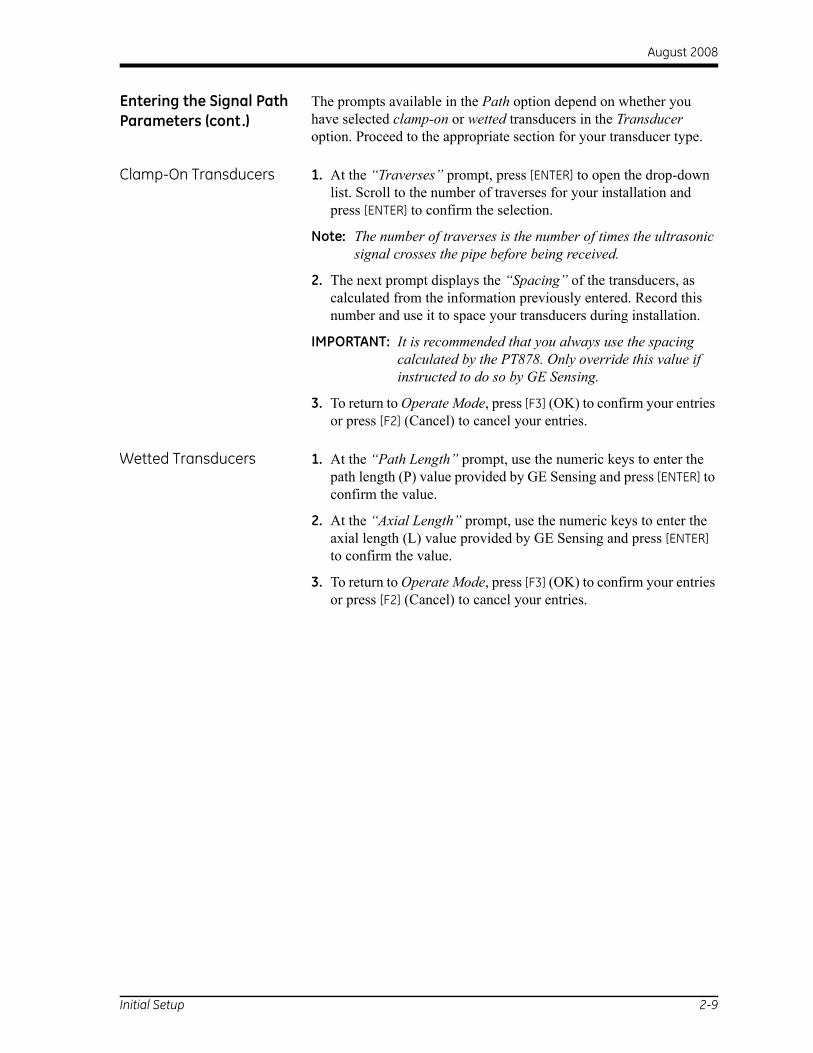
The prompts available in the Path option depend on whether you have selected clamp-on or wetted transducers in the Transducer option. Proceed to the appropriate section for your transducer type.
Clamp-On Transducers 1. At the “Traverses” prompt, press [ENTER] to open the drop-down list. Scroll to the number of traverses for your installation and press [ENTER] to confirm the selection.
Note: The number of traverses is the number of times the ultrasonic signal crosses the pipe before being received.
2. The next prompt displays the “Spacing” of the transducers, as calculated from the information previously entered. Record this number and use it to space your transducers during installation.
IMPORTANT: It is recommended that you always use the spacing calculated by the PT878. Only override this value if instructed to do so by GE Sensing.
3. To return to Operate Mode, press [F3] (OK) to confirm your entries or press [F2] (Cancel) to cancel your entries.
Wetted Transducers 1. At the “Path Length” prompt, use the numeric keys to enter the path length (P) value provided by GE Sensing and press [ENTER] to confirm the value.
2. At the “Axial Length” prompt, use the numeric keys to enter the axial length (L) value provided by GE Sensing and press [ENTER] to confirm the value.
3. To return to Operate Mode, press [F3] (OK) to confirm your entries or press [F2] (Cancel) to cancel your entries.
Initial Setup 2-9

August 2008
Entering Correction Factors
To enter Reynolds Correction or Calibration Factor data, scroll to the Correction Factors tab in the Program Menu and press [ENTER].
Entering Reynolds Correction Data
Scroll to the “Reynolds Correction” tab (see Figure 2-7 below), then press [ENTER] and proceed as follows:
Note: The Reynolds Correction factor is based on the kinematic viscosity and the flow rate of the fluid. The default condition is ON, and it should be left that way for all clamp-on transducer applications and most wetted transducer applications.
Figure 2-7: The Reynolds Correction Window
1. To enable or disable Reynolds Correction, use the [ ] and [ ] keys to scroll to the appropriate radio button and press [ENTER].
Note: If you disable Reynolds Correction, you cannot enter any other data in this window. Skip the remaining steps.
2. You must now choose to enter either a single K/V (kinematic viscosity) value or a table of values. Use the [ ] and [ ] keys to scroll to the desired radio button and press [ENTER].
Proceed to the appropriate sub-section on the next page.
Reynolds Correctio Inputs
Correction Factors
Cancel OK
Calibration Factor
Re Correction On Off
K/V (v) m3/s
Data Source
K/V Factor Single Table
Edit Table
10
2-10 Initial Setup
August 2008
Entering Reynolds Correction Data (cont.)
Entering a Single K/V Value
a. If you chose to enter a single value, press [ENTER] to open the text box.
b. Use the numeric keys to enter the K/V value for your fluid (see the Sound Speeds and Pipe Size Data booklet).
c. Press [ENTER] to confirm your data.
Entering a Table of K/V Values
a. If you chose to enter a table of values, press [ENTER] to open the data source box.
b. Press [F3] (OK) to confirm velocity as the source parameter.
c. At the Edit Table prompt, press [ENTER] to open the table of data. Use the arrows keys to scroll to each table cell, and use the numeric keys to enter the value for each cell.
d. When done, press [F3] (OK) to confirm the new table.
3. To return to Operate Mode, press [F3] (OK) to confirm your entries or press [F2] (Cancel) to cancel your entries.
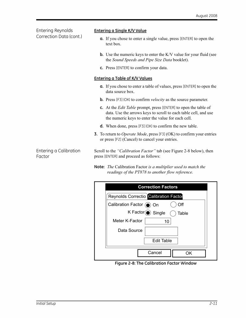
Entering a Calibration Factor
Scroll to the “Calibration Factor” tab (see Figure 2-8 below), then press [ENTER] and proceed as follows:
Note: The Calibration Factor is a multiplier used to match the readings of the PT878 to another flow reference.
Figure 2-8: The Calibration Factor Window
Reynolds Correctio Inputs
Correction Factors
Calibration Factor
Calibration Factor On Off
Meter K-Factor
Data Source
K Factor Single Table
10
Edit Table
Cancel OK
Initial Setup 2-11

August 2008
Entering a Calibration Factor (cont.)
1. To enable or disable Calibration Factor, use the [ ] and [ ] keys to scroll to the appropriate radio button and press [ENTER].
2. You must now choose to enter either a single K Factor or a table of values. Use the [ ] and [ ] keys to scroll to the desired radio button and press [ENTER].
Proceed to the appropriate sub-section below.
Entering a Single K Factor
a. If you chose to enter a single value, press [ENTER] to open the text box.
b. Use the numeric keys to enter the desired K Factor.
Note: If you have enabled the Reynolds Correction factor, the K-Factor should be set to 1.00. Otherwise, a typical K-Factor is between 0.5 and 2.00).
c. Press [ENTER] to confirm your data.
Entering a Table of K/V Values
a. If you chose to enter a table of values, press [ENTER] to open the data source box.
b. Press [F3] (OK) to confirm velocity as the source parameter.
c. At the Edit Table prompt, press [ENTER] to open the table of data. Use the arrows keys to scroll to each table cell, and use the numeric keys to enter the value for each cell.
d. When done, press [F3] (OK) to confirm the new table.
3. To return to Operate Mode, press [F3] (OK) to confirm your entries or press [F2] (Cancel) to cancel your entries.
2-12 Initial Setup

Chapter 3

Operation
Configuring The Display Options . . . . . . . . . . . . . . . . . . . . . . . . . . . . . . . . . 3-1
Customizing the Display Screen . . . . . . . . . . . . . . . . . . . . . . . . . . . . . . . . . . 3-7
Error Messages . . . . . . . . . . . . . . . . . . . . . . . . . . . . . . . . . . . . . . . . . . . . . . . . 3-12
Programming Global Meter Settings . . . . . . . . . . . . . . . . . . . . . . . . . . . . . 3-13

August 2008
Configuring The Display Options
The PT878 allows you to view 1 to 4 different measurement parameters simultaneously in either numeric or graphical format. To configure the display, press [SEL] from the Operate Mode window and a cursor appears next to the parameter closest to the upper left corner (see Figure 3-1 below). Use the [SEL] key to scroll through the displayed measurements until you reach the desired parameter. Then, press [ENTER] to open the Display Menu for that parameter.
Proceed to the appropriate section for detailed instructions.
Figure 3-1: Display After Pressing [SEL]
2000/11/30 09:53 AM
4Velocity, ft/s
0.0032
Delta-T, ns
0.10 0.0
Volume, l/s
E0: No Errors
ABC.SIT
Signal, dBFormat View Measurement
Operation 3-1

August 2008
The Format Option The Number Format option, allows you to specify the type of notation and the number of decimal places for the selected parameter (see Figure 3-2 below).
Note: For a line or bar graph display, the Limits option appears instead of the Format option.
Figure 3-2: The Number Format Window
1. Use the arrow keys to select the Format option and press [ENTER] to open the drop-down list of three format choices (Default, Fixed Decimal, and Scientific).
2. Scroll to the desired number format and press [ENTER] to confirm your choice.
3. Use the arrow keys to select the Decimal Places option and press [ENTER] to open the drop-down list of choices (0, 1, 2, 3, and 4).
4. Scroll to the desired number of decimal places and press [ENTER] to confirm your choice.
5. Press [F3] (OK) to confirm your selections and return to Operate Mode. Otherwise, you can press [F2] (Cancel) or the [ESC] key to exit the Format Menu without confirming your selections.
Programming
Number Format
Cancel OK
Format Fixed Decimal
Decimal Places 2
3-2 Operation

August 2008
The View Option The View option, allows you to specify the type of display for the selected parameter.
1. Use the arrow keys to select the View option.
2. Press [ENTER] to open the drop-down list of three display types (Numeric, Line Graph, and Bar Graph).
3. Scroll to the desired display type and press [ENTER] to confirm your choice.
The display immediately changes to reflect the choice made above. For example, if you chose a Line Graph display, the screen appears similar to Figure 3-3 below.
Figure 3-3: Display After Format Change
2000/11/30 09:53 AM
Velocity, ft/s
32
Delta-T, ns
0.10 0.0
Volume, l/s
E0: No Errors
ABC.SIT
Signal, dB12.2
12.2-10 Seconds
-0.6014
Operation 3-3

August 2008
The Limits Option For a graphical display, the Limits option enables you to program:
• the minimum or maximum values displayed
• the time interval
• the display of the average value
Note: For a numeric display, the Format option appears instead of the Limits option.
1. Use the arrow keys to select the Limits option and press [ENTER].
2. At the Change drop-down menu option, press [ENTER] again and a window similar to Figure 3-4 below appears.
Figure 3-4: The Line Graph Parameters Window
3. Scroll to the Minimum text box and press [ENTER] to open the box.
4. Use the numeric keys to enter the minimum value to be displayed on the graph. Press [ENTER] to confirm the value.
5. Scroll to the Maximum text box and press [ENTER] to open the box.
6. Use the numeric keys to enter the maximum value to be displayed on the graph. Press [ENTER] to confirm the value.
Programming
Set Line Graph Parameters
Cancel OK
Velocity
Use Lines
Plot Average Value
10 Seconds
-12.2Minimum
Maximum 12.2
Show Minimum and Maximum
3-4 Operation

August 2008
The Limits Option (cont.) For a bar graph display, skip the following steps and proceed directly to the final paragraph below. For a line graph display, complete the following additional steps:
1. Scroll to the text box for the x-axis interval value and press [ENTER] to open the box.
2. Use the numeric keys to enter the desired interval value and press [ENTER] to confirm the value.
3. Scroll to the text box for the x-axis units and press [ENTER] to open the box.
4. Use the numeric keys to enter the desired interval units (seconds, minutes, hours, or days) and press [ENTER] to confirm the choice.
5. The final three menu options permit you to configure some of the display details:
a. If you want to use lines to connect the data points, scroll to the Use Lines option and press [ENTER] to select it.
b. If you want to show the average value for the displayed parameter, scroll to the Plot Average value option and press [ENTER] to select it.
c. If you want to show the minimum and maximum values for the displayed parameter, scroll to the Show Minimum and Maximum option and press [ENTER] to select it.
Press [F3] (OK) to confirm your selections and return to Operate Mode. When you return to Operate Mode, the screen will display any changes you have made. Otherwise, you can press [F2] (Cancel) or the [ESC] key to exit the Format Menu without confirming your selections.
Operation 3-5
August 2008
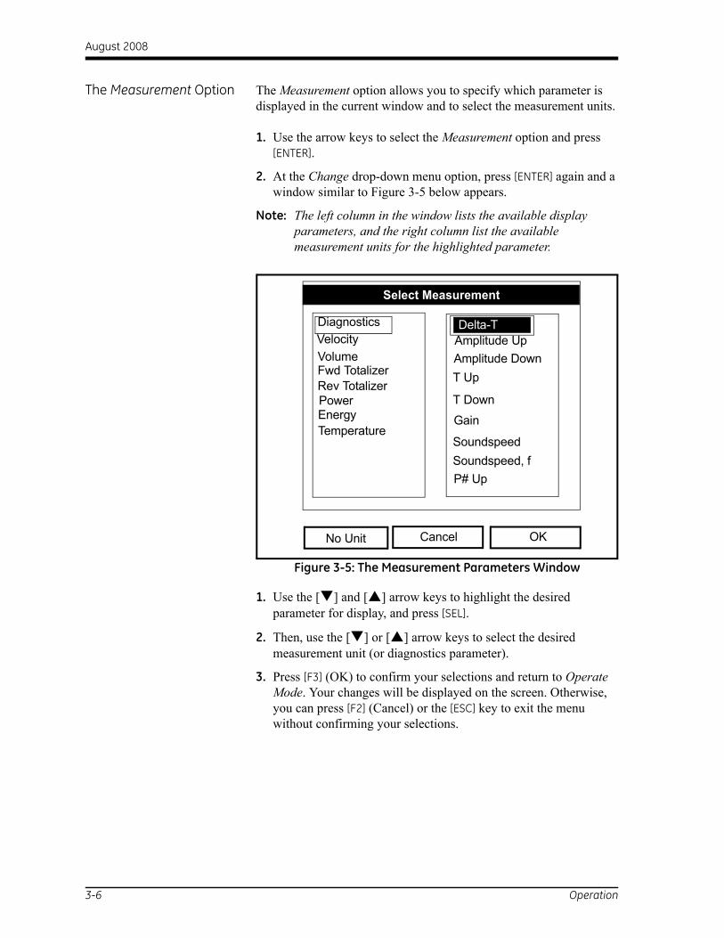
The Measurement Option The Measurement option allows you to specify which parameter is displayed in the current window and to select the measurement units.
1. Use the arrow keys to select the Measurement option and press [ENTER].
2. At the Change drop-down menu option, press [ENTER] again and a window similar to Figure 3-5 below appears.
Note: The left column in the window lists the available display parameters, and the right column list the available measurement units for the highlighted parameter.
Figure 3-5: The Measurement Parameters Window
1. Use the [ ] and [ ] arrow keys to highlight the desired parameter for display, and press [SEL].
2. Then, use the [ ] or [ ] arrow keys to select the desired measurement unit (or diagnostics parameter).
3. Press [F3] (OK) to confirm your selections and return to Operate Mode. Your changes will be displayed on the screen. Otherwise, you can press [F2] (Cancel) or the [ESC] key to exit the menu without confirming your selections.
Programming
Select Measurement
Cancel OK
VolumeAmplitude UpDelta-T
Velocity
Fwd TotalizerRev Totalizer
Diagnostics
No Unit
Amplitude DownT Up
T Down
Gain
SoundspeedSoundspeed, fP# Up
Delta-T
PowerEnergyTemperature
3-6 Operation

August 2008
Customizing the Display Screen
The Site Menu enables you to customize your display screen. To enter the Site Menu:
Note: As an aid in following the programming instructions in this manual, refer to Appendix A, Menu Maps.
1. Press the [MENU] key at the lower right of the PT878 keypad. The Menu Bar replaces the Status Bar at the top of the screen.
2. With the Site Menu highlighted, press [ENTER] and a screen similar to Figure 3-6 below appears.
Figure 3-6: The Site Menu
Proceed to the appropriate section to specify the number of displayed parameters or to customize the softkeys.
Meter Logging Service
Velocity, ft/s
0.0032
Delta-T, ns
0.10 0.0
Volume, l/s
E0: No Errors
Signal, dBSave Now
1 View2 View3 View4 View
Drive Manager
FKeys 4
ManagerSite Program
About
Operation 3-7

August 2008
Specifying the Number of Displayed Parameters
To change the number of open display windows, use the [ ]or [ ] arrow keys to move to the desired number of views (1 View, 2 View, 3 View, or 4 View) and press [ENTER]. The screen then displays the specified number of windows. For example, Figure 3-7 below shows a screen configured to display one window.
Figure 3-7: “1 View” Display
Note: The PT878 display windows are numbered with #1 at the upper left, #2 at the upper right, #3 at the bottom left, and #4 at the bottom right. The number of views selected will use the appropriate number of these windows in numerical order. For example, if you select a “2 View” display, windows #1 and #2 will be displayed.
2000/11/30 09:53 AM
Velocity, ft/s
E0: No Errors
ABC.SIT
12.2
-12.2
10 Seconds
-0.6014
3-8 Operation

August 2008
Customizing the Softkeys If you use certain menus frequently, you can program your PT878 to access these menus directly from Operate Mode by customizing the softkeys ([F1], [F2] and [F3]). Then, pressing the associated softkey at any time will open the programmed menu directly. To program your softkeys, proceed to the appropriate section.
IMPORTANT: Softkey programming is saved globally. Thus, the same assignments apply to all site files.
Setting a Softkey from the Site Menu:
1. Press the [MENU] key at the lower right of the PT878 keypad. The Menu Bar replaces the Status Bar at the top of the screen.
2. With the Site Menu highlighted, press [ENTER] to open the Site Menu window (see Figure 3-6 on page 3-7).
3. Use the [ ] or [ ] arrow keys to move to the FKeys option and press [ENTER]. A screen similar to Figure 3-8 below appears.
Figure 3-8: The FKeys Menu
4. Use the [ ] or [ ] arrow keys to select the desired FKey (for example, F1) and press [ENTER]. The Configure FKey window (see Figure 3-9 on the next page) opens.
Meter Logging Service
Velocity, ft/s
0.0032
Delta-T, ns
0.10 0.0
Volume, l/s
E0: No Errors
Signal, dBSave Now
1 View2 Views3 Views4 ViewsDrive Manager
ManagerSite Program
FKeys
4F2F3Clear F1Clear F2Clear F3
F1About
Operation 3-9

August 2008
Customizing the Softkeys (cont.)
Figure 3-9: The Configure FKey Window
5. Press [ENTER] to open the menu drop-down list and use the [ ] and [ ] arrow keys to scroll to the desired menu (for example, Contrast).
6. Press [ENTER] to program your selection. Then, press [F3] (OK) to confirm the entry and close the window. (Press [F2] (Cancel) to close the window without changing the key.)
The display now appears similar to Figure 3-10 below, and you can enter the Contrast menu directly by pressing the [F1] softkey.
Figure 3-10: The Programmed Softkey
Configure FKey
Cancel OK
Select a menu item
(Clear)
2000/11/30 09:53 AM
Velocity, m/s Gain, dB
-6
Delta-T, ns
-1.65 0.0
Volume, l/s
E2: Soundspeed
5000
-5000
-1.5121
10 0.4 -30 3
ABC.SIT
Contrast
3-10 Operation

August 2008
Customizing the Softkeys (cont.)
Setting a Softkey from the Target Menu:
1. Press the [MENU] key at the lower right of the PT878 keypad. The Menu Bar replaces the Status Bar at the top of the screen.
2. Navigate to the desired menu (see the Menu Maps in Appendix A for guidance).
3. Use the [ ] or [ ] arrow keys to move to scroll to the desired menu option.
4. Press the desired softkey. A window appears with the question, “Assign current menu command to FKeyX?”
5. Press [F3] (Yes) to confirm the assignment and close the window. (Press [F2] (No) to close the window without changing the key.)
Clearing a Softkey:
1. Press the [MENU] key at the lower right of the PT878 keypad. The Menu Bar replaces the Status Bar at the top of the screen.
2. With the Site Menu highlighted, press [ENTER] to open the Site Menu window (see Figure 3-6 on page 3-7).
3. Use the [ ] or [ ] arrow keys to move to the FKeys option and press [ENTER]. A screen similar to Figure 3-8 on page 3-9 appears.
4. Use the [ ] or [ ] arrow keys to move to the desired Clear FKey (F1, F2 or F3) option on the menu. Press [ENTER].
The meter returns to Operate Mode, and the corresponding softkey is now cleared.
Note: A softkey can also be cleared in the Configure FKey window (see Figure 3-9 on page 3-10) by selecting the Clear option and pressing [ENTER] and then [F3] (OK).
Operation 3-11

August 2008
Error Messages To indicate a possible problem during a measurement, Error Messages may occasionally appear on the PT878 display. The possible Error Messages, along with tips for isolating and correcting the problem, are listed in Table 3-1 below.
Note: On a graphical display, errors are indicated by a vertical gray bar at the point of the error. On a numeric display, errors are indicated by an error code in place of the measurement.
Table 3-1: Error Code MessagesError Problem Possible Cause Action
E0 No error • Displays briefly after clearing another error message
None required - measurement is valid.
E1 Low Signal - Poor ultrasonic signal strength
• Broken cable• Flowcell problem• Transducer problem• Electronic failure
• Check transducer cable• Check programming and
transducer spacing• Contact the factory if problem
persists.E2 Sound Speed Error • Poor flow conditions
• Incorrect programming• Bad transducer spacing• Measurement is very different
from the programmed sound speed
• Check sound speed against nominal sound speed
• Check programming and transducer spacing
E3 Velocity Range - Velocity exceeds programmed limits
• Programming error• Poor flow conditions• Bad transducer spacing
• Make sure flow rate is within ±12 m/s (±40 ft/s)
• Check programming and transducer spacing
E4 Signal Quality • If too high - electronic failure• If too low - flowcell, electrical
problem
• Check for source of electrical interference
• Check electronics with a test flowcell
• If unit still fails to operate, contact the factory
E5 Amplitude Error • Excessive particles or bubbles in fluid
• High second phase percentage
• Check for flowcell problems
E6 Cycle skip, Acceleration • Poor flow conditions• Bad transducer spacing
• Check transducer spacing as programmed and as set on pipe
E7 Analog Out Error • Under current output • Check that output load is <550 ohm
E8 Temperature Input Supply
• Supply temperature input out of range
• Check cable and transmitter
E9 Temperature Input Return • Return temperature input out of range
• Check cable and transmitter
3-12 Operation

August 2008
Programming Global Meter Settings
Using the Meter Menu, you can program global settings for the meter that suit your individual preferences. To enter the Meter Menu:
Note: As an aid in following the programming instructions in this manual, refer to Appendix A, Menu Maps.
1. Press the [MENU] key at the lower right of the PT878 keypad. The Menu Bar replaces the Status Bar at the top of the screen.
2. Scroll across until the Meter Menu tab is highlighted, and press [ENTER]. A window similar to Figure 3-11 below opens.
Figure 3-11: The Meter Menu Window
Use the [ ] or [ ] arrow keys to highlight the desired menu option and press [ENTER] to open the option window. Proceed to the appropriate section for programming instructions.
Note: The Language, User Tables, and Snapshot options are not discussed in this abridged manual. Refer to your full PT878 manual (910-219) information on these options.
Velocity, ft/s Signal, dB
0.0032
Delta-T, ns
0.10 0.0
Volume, l/s
E0: No Errors
Site Program Meter Logging Service
UnitsDate/TimeLocaleContrastBacklight
Units
LanguageCommunicationTotals
Battery
User Tables√Snapshot
Operation 3-13

August 2008
The Units Option The Units option enables you to select either English or Metric as the global measurement units for the PT878. The selected units then become the default for every measurement that is taken.
1. Access the Meter Menu as described on page 3-13.
2. Scroll to the Units option and press [ENTER]. The Meter Settings window opens (see Figure 3-12 below).
Figure 3-12: The Meter Settings Window
3. Use the [ ] and [ ] keys to select the desired measurement units, and press [ENTER] to confirm the choice.
4. Press [F3] (OK) to confirm the choice and close the window, or press [F2] (Cancel) to close the window without making the change.
Meter Settings
Cancel OK
Units
English Metric
Date:2000/11/1
Time:10:08:53
3-14 Operation

August 2008
The Battery Charger Option
The Battery option allows you to monitor the run time and status of the internal rechargeable batteries, as well as to condition NiCad batteries to maintain the maximum life.
Note: When conditioning the batteries, be sure you have plugged the AC adapter into the PT878 and pressed the power key. NiMH batteries normally do not require conditioning.
1. Access the Meter Menu as described on page 3-13.
2. Scroll to the Battery option and press [ENTER]. The Battery Charger window opens (see Figure 3-13 below).
Figure 3-13: The Battery Charger Window
3. Press [ENTER] to open the Part Number list box. Scroll to the battery type you have installed [1.8 Ahr NiCd (200-058) or3.0 Ahr NiMH (200-081)] and press [ENTER].
Note: If you do not set the correct battery type in the Part Number window, the battery continues to function, but the battery status icons will not be accurate.
4. With the Condition Battery box selected, press [ENTER]. The Condition Battery window status line should change from Stop to Discharging within 30 seconds.
Note: You should condition NiCad batteries when the Run Time Remaining is reduced to 50% of their previous run time.
5. To stop the discharge cycle, press [ENTER] and note that the status line in the Condition Battery window changes to On Charger.
6. Press [F3] (OK) to return to Operate Mode.
Battery Charger
Cancel OK
Status: Full Charge
Battery Voltage: 5.78 VoltsBattery Type: NiCd
Condition Battery
Run Time Remaining:
Backup Battery: OK Part Number: 1.8Ahr NiCd (200-058)
Operation 3-15

August 2008
The Date/Time Option In Operate Mode, the PT878 Status Bar displays the current date and time in the upper right corner of the screen. The Date/Time option allows you to set these values to ensure accurate data logging.
1. Access the Meter Menu as described on page 3-13.
2. Scroll to the Date/Time option and press [ENTER]. The Meter Settings window opens (see Figure 3-12 on page 3-14).
3. Scroll to the Date text box, which displays the current meter date, and press [ENTER].
4. Use the [ ] and [ ] keys to scroll to the year, month, or day and use the numeric keys to enter the desired number.
5. When done, press [ENTER] to confirm the new date.
Note: Instead of using the numeric keys, you may use the [ ] or [ ] arrow keys to change the date numbers in 1-digit increments.
To change the time, proceed in a similar manner:
1. Access the Meter Menu as described on page 3-13.
2. Scroll to the Date/Time option and press [ENTER]. The Meter Settings window opens (see Figure 3-12 on page 3-14).
3. Scroll to the Time text box, which displays the current meter time, and press [ENTER].
4. Use the [ ] and [ ] keys to scroll to the hours, minutes, or seconds and use the numeric keys to enter the desired number.
5. When done, press [ENTER] to confirm the new time.
Note: Instead of using the numeric keys, you may use the [ ] or [ ] arrow keys to change the time numbers in 1-digit increments.
Press [F3] (OK) to confirm your entries and return to Operate Mode. Your changes will be displayed on the screen. Otherwise, you can press [F2] (Cancel) or the [ESC] key to exit the menu without confirming your entries.
3-16 Operation

August 2008
The Locale Option In addition to setting the correct date and time, you can also change their format to suit local preferences. This is accomplished using the Locale option.
1. Access the Meter Menu as described on page 3-13.
2. Scroll to the Locale option and press [ENTER]. The Locale tab of the Display Options window opens (see Figure 3-14 below).
Figure 3-14: Locale Tab Window
3. The Separators section allows you to select the symbols used in the following items:
a. Scroll to the Date text box and press [ENTER] to open the drop-down list. Select a dash (-), comma (,) or slash (/) for the date separator and press [ENTER] to confirm your choice.
b. Scroll to the Time text box and press [ENTER] to open the drop-down list. Select a period (.) or colon (:) for the time separator and press [ENTER] to confirm your choice.
c. Scroll to the Decimal text box and press [ENTER] to open the drop-down list. Select a period (.) or comma (,) for the decimal separator and press [ENTER] to confirm your choice.
Display
Display Options
Locale
Date Format
Separators:
Time Format
Time
Date/Time, Decimal Formats:
MM/DD/YYYY
/
12 Hour
:
MM/DD/YYYY HH:MM:SS PM, 123.45
Cancel OK
DecimalDate .
Operation 3-17

August 2008
The Locale Option (cont.) 4. Use the [ ] or [ ] arrow keys to scroll to the Date Format text box and press [ENTER]. The drop down menu offers the following options:
• YYYY/MM/DD (year/month/day)
• MM/DD/YYYY (month/day/year)
• DD/MM/YYYY (day/month/year)
Use the [ ] or [ ] arrow keys to scroll to the desired format and press [ENTER] to confirm your selection.
5. Use the [ ] or [ ] arrow keys to scroll to the Time Format text box and press [ENTER]. The drop down menu offers the following options:
• 12 Hour (for example, 11:53:23 PM)
• 24 Hour (for example, 23:53:23)
Use the [ ] or [ ] arrow keys to scroll to the desired format and press [ENTER] to confirm your selection.
Note: A line at the bottom of the Locale windows shows how your selections will appear on the display screen.
6. When you are satisfied with your selections, use the arrow keys to return to the Locale tab.
7. Press [F3] (OK) to confirm your selections and return to Operate Mode. Your changes will be displayed on the screen. Otherwise, you can press [F2] (Cancel) or the [ESC] key to exit the menu without confirming your selections.
3-18 Operation

August 2008
The Contrast Option For more comfortable viewing, the PT878 enables you to adjust the screen contrast. To use the Contrast option:
1. Access the Meter Menu as described on page 3-13.
2. Scroll to the Contrast option and press [ENTER]. The Display Options window opens (see Figure 3-15 below).
Figure 3-15: Display Tab Window
3. Scroll to the Darker or Lighter box, and press the [ENTER] button repeatedly until the screen has the desired contrast.
Note: If the screen becomes too dark or too light, scroll to the other box and press [ENTER] until you have adjusted the screen to your satisfaction.
4. Press [F3] (OK) to confirm your adjustments and return to Operate Mode. Your changes will be displayed on the screen. Otherwise, you can press [F2] (Cancel) or the [ESC] key to exit the menu without confirming your adjustments.
Display
Display Options
Cancel OK
Format
Darker
Lighter
Backlight Off Min3
Language English
Operation 3-19

August 2008
The Backlight Option To conserve battery power, the PT878 enables you to adjust how long the backlight remains ON without any user input. To use the Backlight option:
Note: You can manually turn the backlight ON or OFF at any time by pressing the power switch for 1 second.
1. Access the Meter Menu as described on page 3-13.
2. Scroll to the Backlight option and press [ENTER]. The Display Options window opens (see Figure 3-15 on the previous page).
3. Scroll to the Backlight Off text box, and press the [ENTER] button to access the text box.
4. Use the numeric keys to enter the number of minutes that the backlight remains ON (from 0 to 99), and press [ENTER] to confirm the value.
5. Press [F3] (OK) to confirm your entry and return to Operate Mode. Otherwise, you can press [F2] (Cancel) or the [ESC] key to exit the menu without confirming your entry.
The Language Option IMPORTANT: Before using this option, one or more of the available language translation files must be loaded into the meter. Contact GE Sensing for assisitance.
The PT878 offers a selection of several languages for its display. To change the current display language (US English is the default):
1. Access the Meter Menu as described on page 3-13.
2. Scroll to the Language option and press [ENTER]. The Display Options window opens (see Figure 3-15 on the previous page).
3. Scroll to the Language text box, and press the [ENTER] button to access the drop-down list.
4. Scroll to the desired language and press the [ENTER] button to confirm the selection. Then, press [F3] (OK).
3-20 Operation

August 2008
The Language Option (cont.)
5. Changing the language requires restarting the PT878. When a window like the one in Figure 3-16 below appears, press [F2] to cancel the change or [F3] to confirm the change.
Figure 3-16: Change Language Confirmation Window
The meter will now restart in Operate Mode in the new language.
The Communications Option
To configure the PT878 wireless infrared interface, use the Communication option:
1. Access the Meter Menu as described on page 3-13.
2. Scroll to the Communication option and press [ENTER]. The Communications window opens (see Figure 3-17 below).
Figure 3-17: The Communications Window
Change Language
Cancel OK
Choose CANCEL to exit or OK toproceed.
Changing the meter’s languagerequires a restart.
Communications
Node ID 2
Comm Interface IrDA IR 232
Baud Rate 9600 bps
Parity NoneStop Bits
Data Bits
1 2
7 8
Cancel OK
Operation 3-21

August 2008
The Communications Option (cont.)
3. Scroll to the Node ID prompt and press [ENTER] to open the text box. Use the numeric keys to enter a node identification number (must be an integer between 1 and 240) for your PT878 and press [ENTER] to confirm the entry.
IMPORTANT: Do NOT change the default Node ID unless instructed to do so by GE Sensing.
4. Scroll to the Comm Interface prompt and use the [ ] and [ ] keys to select either the IrDA (Infrared Data Association) option or the IR232 (virtual interface) option. Press [ENTER] to confirm your selection.
Note: You must choose the IrDA option when using an IR printer or a file transfer application such as QuickBeam.
IMPORTANT: If you select the IR232 option above, you must use the default values in the next four steps.
5. Scroll to the Baud Rate prompt and press [ENTER] to open the drop-down list. Use the [ ] or [ ] arrow keys to scroll to the desired baud rate (the default is 9600), and press [ENTER] to confirm your selection.
6. Scroll to the Parity prompt and press [ENTER] to open the drop-down list. Use the [ ] or [ ] arrow keys to scroll to the desired parity setting (the default is None), and press [ENTER] to confirm your selection.
7. Scroll to the Stop Bits prompt and use the [ ] and [ ] keys to select either the 1 option or the 2 option (the default is 1). Press [ENTER] to confirm your selection.
8. Scroll to the Data Bits prompt and use the [ ] and [ ] keys to select either the 7 option or the 8 option (the default is 8). Press [ENTER] to confirm your selection.
Press [F3] (OK) to confirm your selections and return to Operate Mode. Otherwise, you can press [F2] (Cancel) or the [ESC] key to exit the menu without confirming your selections.
3-22 Operation

August 2008
The Totals Option The PT878 features both Forward and Reverse Totalizer functions. If it becomes necessary to reset one or both of these totalizers, use the Totals option as follows:
1. Access the Meter Menu as described on page 3-13.
2. Scroll to the Totals option and press [ENTER]. A submenu with the options shown in Figure 3-18 below opens.
Figure 3-18: The Totals Submenu
3. Use the [ ] or [ ] arrow keys to choose the desired option, and press [ENTER] confirm your choice.
Based on the selection you made above, the meter immediately resets both totalizers, the forward totalizer, or the reverse totalizer to 0.0 and returns to Operate Mode.
Velocity, ft/s Signal, dB
0.0032
Delta-T, ns
0.10 0.0
Volume, l/s
E0: No Errors
Site Program Meter Logging Service
UnitsDate/TimeLocaleContrastBacklight
Units
LanguageCommunication
Battery
User TablesTotals
Reset BothReReset Fwd TotalReset Rev Total
Snapsho
Operation 3-23

Chapter 4

Managing Site Files
The Site Menu . . . . . . . . . . . . . . . . . . . . . . . . . . . . . . . . . . . . . . . . . . . . . . . . . . 4-1
The Site Manager Window . . . . . . . . . . . . . . . . . . . . . . . . . . . . . . . . . . . . . . . 4-2
The Site Manager Menu . . . . . . . . . . . . . . . . . . . . . . . . . . . . . . . . . . . . . . . . . 4-3

August 2008
The Site Menu So that you don’t need to reenter all of your initial setup data (see Chapter 1) each time you use the meter, the PT878 can store this site data in files. Then, the Site Menu enables you to create and manage these site files.
To access the Site Menu, proceed as follows:
1. Press the [MENU] key at the lower right of the PT878 keypad. The Menu Bar replaces the Status Bar at the top of the screen.
2. With the Site Menu highlighted, press [ENTER] and a screen similar to Figure 4-1 below appears.
Note: As an aid in following the programming instructions in this manual, refer to Appendix A, Menu Maps.
Figure 4-1: The Site Menu
Meter Logging Service
Velocity, ft/s
0.0032
Delta-T, ns
0.10 0.0
Volume, l/s
E0: No Errors
Signal, dBSave Now
1 View2 View3 View4 View
Drive ManagerFKeys 4
Site ManagerSite Program
About
Managing Site Files 4-1

August 2008
The Site Manager Window
The Site Manager is the tool that is used to perform a variety of operations on site files. To access the Site Manager, proceed as follows:
1. Access the Site Menu, as described on the previous page.
2. With the Site Menu highlighted, scroll to the Site Manager option and press [ENTER]. A screen similar to Figure 4-2 below appears.
Figure 4-2: The Site Manager Window
Note: Each PT878 comes preprogrammed with a basic site, called Default, that can be used as a template for creating new sites.
The box on the left site of the Site Manager window lists all of the site files currently in the PT878 memory. You can use the [ ] and [ ] arrow keys to scroll through this list. The right section of the window shows information for the highlighted site, such as its date, time and size, as well as the remaining amount of free memory.
Site Manager
Info: DEFAULT:SIT
09/04/00 14:51:105111 bytes118272 bytes free
Cancel OK
DEFAULTNew Site
Convert
File
**CURRENT SITE**
Site Sort
4-2 Managing Site Files

August 2008
The Site Manager Menu To open the Site Manager menu, proceed as follows:
1. At the Site Manager window, press [MENU] and then [ENTER]. A window similar to Figure 4-3 below opens.
Figure 4-3: The Site Manager Menu
Use the [ ] and [ ] arrow keys to select the desired option from the above menu and proceed to the appropriate section for instructions.
The New Option 1. Scroll to the New option in the Site Manager menu and press [ENTER]. A screen similar to Figure 4-4 below appears.
Figure 4-4: Site Name Window
Site ManagerFile
Info: DEFAULT:SIT
09/04/00 14:51:105111 bytes118272 bytes free
Exit
DEFAULTNew Site
NewOpenSaveSave As
RenameDelete
Site Sort
Refresh
Refresh
A B C D E F G HI J K L M N O PQ R S T U V W XY Z 0 1 2 3 4 56 7 8 9
New Site
Delete Cancel OK
Site 01
- _ @ #& ( )
Managing Site Files 4-3

August 2008
The New Option (cont.) 2. To begin entering a name for the new site, use the four arrow keys to scroll to the desired letter or number, and press [ENTER].
3. Repeat the previous step until you have created a site name of up to eight characters.
Note: At any time, you may press [F1] (Delete) to remove the last character entered.
4. When you have finished, press [F3] (OK) to accept the name, or press [F2] (Cancel) to leave the window without creating a new site.
If you pressed [F3] above, a window similar to that in Figure 4-5 below appears.
Figure 4-5: Template Confirmation Window
You must now decide if you want to use the site that was highlighted in the Site Manager window (see Figure 4-2 on page 4-2) as a template for the new site:
• Press [F2] (No) if you do not want to use the selected site as a template (you will use the current setup data instead)
• Press [F3] (Yes) if you do want to use the selected site as a template for the new site
After you make your selection, the meter returns to Operate Mode, and the new site name is shown in the upper left corner of the display.
A B C D E F G HI J K L M N O PQ R S T U V W XY Z 0 1 2 3 4 56 7 8 9
New Site
No Yes
New Site
Use the selected site‘DEFAULT.SIT’ as a template?
4-4 Managing Site Files

August 2008
The Open Option To recall a site that has been previously created and saved:
1. Highlight the desired site in the Site Manager window (see Figure 4-2 on page 4-2).
2. Press [MENU] to open the File menu.
3. Scroll to the Open option, and press [ENTER]. A window similar to Figure 4-6 below opens.
IMPORTANT: When you open a previous site, all of the site data currently in memory will be erased.
Figure 4-6: The Open Site Confirmation Window
4. Select one of the following options:
• Press [F2] (No) to cancel opening the selected site
• Press [F3] (Yes) to open the selected site
5. If you decided to open the selected site above, you must decide if you want to save any changes to the current site:
• Press [F2] (No) to erase the changes
• Press [F3] (Yes) to confirm and save the changes
If you pressed [F3] above, the PT878 returns to Operate Mode, and the selected site is shown in the upper left corner of the display.
1 View
Programming
Site Manager
No Yes
Info:DEFAULT
GLOBAL
File
DEFAULT
Open Confirmation
ResReOpen File DEFAULT Are You Sure?
Managing Site Files 4-5

August 2008
The Save Option You can save the current site in one of two ways:
• From the Site Menu (see Figure 4-1 on page 4-1), scroll to the Save Now option and press [ENTER]. Or,
• From the Site Manager (see Figure 4-3 on page 4-3), press [MENU] to open the File menu. Then, scroll to the Save option, and press [ENTER].
In either case, a window similar to Figure 4-7 below opens.
Figure 4-7: The Save Site Window
When the above window opens, respond as follows:
• Press [F2] (No) to cancel saving the current site, or
• Press [F3] (Yes) to save the current site
If you pressed [F3] above, the current site is saved, and the PT878 remains in the current window (Operate Mode or Site Manager).
No Yes
Save the current site(DEFAULT.SIT)?
Save Site
4-6 Managing Site Files

August 2008
The Save As Option To save the current site with a different name:
1. From the Site Manager (see Figure 4-2 on page 4-2), press [MENU] to open the File menu.
2. Scroll to the Save As option and press [ENTER]. A window similar to Figure 4-8 below opens.
Figure 4-8: The Save Current Site Window
3. To begin entering a new name for the current site, use the four arrow keys to scroll to the desired letter or number, and press [ENTER].
4. Repeat the previous step until you have created a site name of up to eight characters.
Note: At any time, you may press [F1] (Delete) to remove the last character entered.
5. When you have finished, press [F3] (OK) to accept the name, or press [F2] (Cancel) to leave the window without creating a new site.
6. When the Save Site window (see Figure 4-7 on page 4-6) appears, press [F2] (No) to cancel saving the site, or press [F3] (Yes) to save the site with the new name.
If you pressed [F3] above, the current site is saved with both the old and new names, and the meter remains in the Site Manager window.
A B C D E F G HI J K L M N O PQ R S T U V W XY Z 0 1 2 3 4 56 7 8 9
Save Current Site
Delete Cancel OK
Managing Site Files 4-7

August 2008
The Refresh Option To update the meter with the most current information, open the Site Manager (see Figure 4-2 on page 4-2). Then, proceed as follows:
• Press [F2] (Refresh), or
• press [MENU] to open the File menu. Then, scroll to the Refresh option and press [ENTER].
The updated site information appears in the Site Manager window.
IMPORTANT: To save the site with the updated data, you must use the Save option (see page 4-6).
The Rename Option To rename a site, proceed as follows:
1. Highlight the existing site in the Site Manager (see Figure 4-2 on page 4-2), and press [MENU] to open the File menu.
2. Scroll to the Rename option and press [ENTER]. A window similar to Figure 4-9 below opens.
Figure 4-9: The Rename Site Window
3. To begin entering a new name for the site, use the four arrow keys to scroll to the desired letter or number, and press [ENTER].
4. Repeat the previous step until you have created a site name of up to eight characters.
Note: At any time, you may press [F1] (Delete) to remove the last character entered.
A B C D E F G HI J K L M N O PQ R S T U V W XY Z 0 1 2 3 4 56 7 8 9
Rename Site
Delete Cancel OK
DEFAULT
4-8 Managing Site Files

August 2008
The Rename Option (cont.) 5. When you have finished, press [F3] (OK) to accept the new name, or press [F2] (Cancel) to leave the window without renaming the site.
The PT878 remains in the Site Manager window, and the site is now listed with the new name.
The Delete Option To delete a site, proceed as follows:
1. Highlight the existing site in the Site Manager (see Figure 4-2 on page 4-2), and press [MENU] to open the File menu.
2. Scroll to the Delete option and press [ENTER]. A window similar to Figure 4-10 below opens.
Figure 4-10: The Delete Confirmation Window
When the above window opens, respond as follows:
• Press [F2] (No) to cancel deleting the indicated site, or
• Press [F3] (Yes) to delete the indicated site
If you pressed [F3] above, the indicated site is deleted and the meter returns to the Site Manager window.
1 View
Programming
Site Manager
No Yes
Info:DEFAULT
GLOBAL
File
DEFAULT
Delete Confirmation
ResReDelete The Site ‘A.SIT’ Are You Sure?
Managing Site Files 4-9

August 2008
The Message Option The Message option in the Site menu allows you to add a descriptive message of up to 30 characters to a site. To create a site message:
1. From the Site Manager (see Figure 4-2 on page 4-2), press [MENU] to open the File menu.
2. Press the [ ] arrow key once to scroll from the File menu to the Site menu.
3. Press [ENTER] and a window similar to Figure 4-11 below opens.
Figure 4-11: The Site Manager>Site Menu
Note: The Transfer and Transfer as Text options are not discussed in this abridged manual. See your full PT878 User’s Manual.
Site ManagerFile
Info: DEFAULT:SIT
09/04/00 14:51:105111 bytes118272 bytes free
Refresh Exit
DEFAULTNew SitePrint
Transfer
SiteMessage
Sort
Transfer as Text
4-10 Managing Site Files

August 2008
The Message Option (cont.)
4. Scroll to the Message option and press [ENTER]. A text entry window similar to Figure 4-12 below opens.
Figure 4-12: The Text Entry Window
5. To begin entering the site message, use the four arrow keys to scroll to the desired character, and press [ENTER].
Note: Pressing [SEL] alternates between windows with upper-case (capital) letters, lower-case letters, and symbols.
6. Repeat the previous step until you have created a site name of up to 30 characters.
Note: At any time, you may press [F1] (Delete) to remove the last character entered.
7. When you have finished, press [F3] (OK) to accept the site message, or press [F2] (Cancel) to leave the window without adding the site message.
The PT878 returns to the Site Manager window.
A B C D E F G H I J
K L M N O P Q R S T
U V W X Y Z 0 1 2 3
4 5 6 7 8 9 . / , “= < >
Delete Cancel OK
‘
Managing Site Files 4-11

August 2008
The Print Option To print the current site, proceed as follows:
1. From the Site Manager (see Figure 4-2 on page 4-2), press [MENU] to open the File menu.
2. Press the [ ] arrow key once to scroll from the File menu to the Site menu (see Figure 4-11 on page 4-10).
3. Scroll to the Print option and press [ENTER].
4. Observe the following responses:
a. The PT878 shows a message indicating that its infrared sensor is searching for a printer.
b. If no printer is found, a window appears indicating that the PT878 cannot find a suitable device.
c. If more than one compatible infrared device is found, you will be required to select the desired device.
5. If a suitable printer is found and selected, the Site Manager window appears.
6. Press [F2] (No) to cancel printing, or press [F3] (Yes) to print the current site.
If you pressed [F3] above, The PT878 returns to Operate Mode and the current site is printed.
4-12 Managing Site Files

Chapter 5

Data Logging
The Logging Menu . . . . . . . . . . . . . . . . . . . . . . . . . . . . . . . . . . . . . . . . . . . . . . 5-1
The Log Manager Window . . . . . . . . . . . . . . . . . . . . . . . . . . . . . . . . . . . . . . . 5-2
The Log Manager Menu . . . . . . . . . . . . . . . . . . . . . . . . . . . . . . . . . . . . . . . . . 5-2

August 2008
The Logging Menu A powerful feature of the PT878 is data logging. The logged data is stored internally in battery-backed-up memory, and a fixed amount of memory is assigned to data logging.
To access the Logging Menu, proceed as follows:
1. Press the [MENU] key at the lower right of the PT878 keypad. The Menu Bar replaces the Status Bar at the top of the screen.
2. Scroll to the Logging Menu and press [ENTER]. A screen similar to Figure 5-1 below appears.
Note: As an aid in following the programming instructions in this manual, refer to Appendix A, Menu Maps.
Figure 5-1: The Logging Menu
Note: For any menu options not discussed in this abridged manual, see your full User’s Manual (910-219).
Velocity, ft/s Signal, dB
0.00 32
Delta-T, ns
0.10 0.0
Volume, l/s
E0: No Errors
Site Program Meter Logging Service
Units
ManagerNew LogTest
Data Logging 5-1

August 2008
The Log Manager Window
The Log Manager is the tool that is used to perform a variety of operations on logs and log files. To access the Log Manager, proceed as follows:
1. Access the Log Menu, as described on the previous page.
2. With the Log Menu highlighted, scroll to the Manager option and press [ENTER]. A screen similar to Figure 5-2 below appears.
Figure 5-2: The Log Manager Window
The box on the left site of the Log Manager window lists all of the logs currently in the PT878 memory. You can use the [ ] and [ ] arrow keys to scroll through this list. The right section of the window shows information for the highlighted log.
IMPORTANT: Logs are associated with the site in use at the time the log is created. By default, the Log Manager lists only the logs for the current site.
The Log Manager Menu To open the Log Manager menu, proceed as follows:
1. At the Log Manager window, press [MENU] and then [ENTER].
2. Use the arrow keys to scroll through the menus and menu options until the desired menu option is highlighted.
3. Press [ENTER] to open the menu.
Proceed to the appropriate section for instructions on specific menus.
Log Manager
Info: AAA.LOG
03/01/01 13:23:211216 bytes109568 bytes free
Refresh Exit
AAABBBCCC
State: Finished
File Log View Sort
S:03/01/01 13:13:41E:03/01/01 13:23:41Interval: 10 SecondsRecords:51
5-2 Data Logging

August 2008
The File Menu The File menu is used to manage your existing log files and to set up new logs. To access the File menu, proceed as follows:
1. At the Log Manager window, press [MENU] and then [ENTER]. A window similar to Figure 5-3 below opens.
Figure 5-3: File Menu in the Log Manager
Use the [ ] and [ ] arrow keys to select the desired option from the above menu and proceed to the appropriate section for instructions.
Log Manager
Info: AAA.LOG
03/01/01 13:23:211216 bytes109568 bytes free
Refresh Exit
AAABBBCCC
State: FinishedS:03/01/01 13:13:41E:03/01/01 13:23:41Interval: 10 SecondsRecords:51
Clone Selected LogRenameDeleteDelete All Logs?
Transfer
File Log View Sort New
RefreshPrint
Data Logging 5-3

August 2008
The New Option The New option enables you to set up the parameters for creation of a new log. To do so, proceed as follows:
1. Perform one of the following procedures:
• In the Log Manager>File menu (see Figure 5-3 on the previous page), scroll to the New option and press [ENTER]. Or,
• In the Logging menu (see Figure 5-1 on page 5-1), scroll to the New Log option and press [ENTER].
2. When the Create New Log windows opens (see Figure 5-4 below), start entering a name for the log by using the four arrow keys to scroll to the desired character and pressing [ENTER].
Figure 5-4: The Create New Log Window
3. Repeat the above procedure until you have completed the log name.
Note: At any time, you may press [F1] (Delete) to remove the last character entered.
4. When you have finished, press [F3] (OK) to accept the name, or press [F2] (Cancel) to leave the window without creating a new log.
If you pressed [F3] above, the General tab of the log configuration window opens (see Figure 5-5 on the next page). Continue on the next page to enter the parameters for the new log.
6 7 8 9 - _ @ #
Delete Cancel OK
A B C D E F G H
I J K L M N O P
Q R S T U V W X
Y Z 0 1 2 3 4 5
Create New Log
& ( )
5-4 Data Logging

August 2008
The New Option (cont.) Note: The Log Name shown in the window is the one you entered on the previous page.
Figure 5-5: The General Log Format Window
1. Scroll to the Format option and use the [ ] and [ ] keys to select either a Linear log or a Circular log. Press [ENTER] to confirm your selection.
2. Scroll to the Type option and use the [ ] and [ ] keys to select either a Standard log or an Error log. Press [ENTER] to confirm your selection.
3. Scroll to the Start Date/Time option and press [ENTER]. Use the [ ] and [ ] keys to highlight each date/time number and enter the desired value. Press [ENTER] to confirm each value.
Note: You may change a value either by entering the new value with the numeric keys or by using the [ ] or [ ] arrow keys to scroll to the desired number.
4. Scroll to the End Date/Time option and press [ENTER]. Use the [ ] and [ ] keys to highlight each date/time number and enter the desired value. Press [ENTER] to confirm each value.
5. Scroll to the Logging Interval option and press [ENTER]. Use the numeric keys to enter the desired logging interval (in seconds), and press [ENTER] to confirm your entry.
The final step is to specify the parameters to be logged. To do this, proceed to the next page.
General Measurements
Cancel Activate
Log Name 10SEC.LOG
End Date/Time
Standard ErrorLinear Circular
TypeFormat
Logging Interval
Start Date/Time 01:38:08
2000/11/01
10
09:38:08
secs
2000/11/01
Data Logging 5-5

August 2008
The New Option (cont.) 1. Use the [ ] and [ ] arrow keys to scroll until the General tab is highlighted.
2. Press the [ ] key to select the Measurements tab. Press [ENTER] and the Measurements window (see Figure 5-6 below) opens.
Figure 5-6: The Measurements Window
3. Scroll to the first table cell and press [ENTER]. The Select Measurement window opens (see Figure 5-7 below).
Figure 5-7: The Select Measurement Window
General NsMeasurements
NO UNIT NO UNIT
Cancel Activate
NO UNIT NO UNIT
NO UNIT NO UNIT
NO UNIT NO UNIT
NO UNIT NO UNIT
NO UNIT NO UNIT
Select Measurement
Cancel OK
Diagnostics
Rev Totalizer
Volume
No Unit
Velocity
Fwd Totalizer
Energy
Meters/secFeet/sec
5-6 Data Logging

August 2008
The New Option (cont.) 4. In the list on the left side of the window, scroll to the output parameter you wish to log and press [SEL] to confirm the choice.
5. When the prompt moves to the list of measurement units on the right side of the window, scroll to the desired units and press [F3] (OK) to confirm your selection.
6. Repeat the previous steps to assign a parameter and measurement units to as many of the 12 table cells as you wish.
7. Press [F3] (Activate) to start the log, or press [F2] (Cancel) to cancel the log.
If you started from the Log Manager>File>New option, the PT878 returns to Operate Mode, with a Pencil icon in the System Tray; if you started it from the Logging Menu>New Log option, the meter returns to the Log Manager.
Data Logging 5-7

August 2008
The Delete Option To delete a log from the PT878 memory, proceed as follows:
1. In the Log Manager window (see Figure 5-2 on page 5-2), use the [ ] and [ ] arrow keys to highlight the log you wish to delete.
2. At the Log Manager window, press [MENU] and then [ENTER].
3. In the File menu, scroll to the Delete option and press [ENTER]. A Delete confirmation window opens (see Figure 5-8 below).
Figure 5-8: The Delete Confirmation Window
4. Press [F3] (Yes) to delete the selected log, or press [F2] (No) to cancel the deletion.
If you pressed [F3] (Yes) above, the log is no longer listed when you return to the Log Manager window.
1 View
Programming
Log Manager
No Yes
Info:DEFAULT
GLOBAL
File
DEFAULT
Delete
ResReDelete Log ‘555.LOG?’
5-8 Data Logging

August 2008
The Delete All Logs? Option
The Delete All Logs? option is used to remove all logs from the PT878 memory. To do this, proceed as follows:
1. In the Log Manager>File menu (see Figure 5-3 on page 5-3), scroll to the Delete All Logs? option and press [ENTER].
2. A window opens and you are asked if you wish to “Delete All Logs?” Press [F3] (Yes) to delete all logs, or press [F2] (No) to cancel the deletion.
If you pressed [F3] above, no logs will be listed when you return to the Log Manager window.
The Transfer Option To transfer a log file from the PT878 memory to the hard drive on a PC, complete the following steps:
Note: You cannot transfer log files from a PC into the PT878 memory.
1. Make sure that the PT878 wireless communications port has been set to the IrDA protocol and that the infrared beam from the PT878 has clear access to the infrared sensor on the PC.
Note: For Windows NT 4.0 systems, make sure the QuickBeam software is running.
2. In the Log Manager window (see Figure 5-2 on page 5-2), use the [ ] and [ ] arrow keys to highlight the log you wish to transfer.
3. At the Log Manager window, press [MENU] and then [ENTER].
4. In the File menu, scroll to the Transfer option and press [ENTER].
5. Observe the following events:
• The screen shows a message indicating that the PT878 is searching for an infrared receiving device.
• If the sensor spots no device, a window appears and you are asked if you want to try again.
• If a device is found, the PT878 shows a message indicating that it is uploading the log (the meter also displays a message if the upload fails).
• When the upload is complete, the meter returns to the Site Manager.
You can open the transferred file with PanaLog Viewer or PanaView and convert it to Microsoft Excel format.
Data Logging 5-9

August 2008
The Log Menu The Log menu is used to manage your active logs. To access the Log menu, proceed as follows:
1. At the Log Manager window, press [MENU] and then [ENTER].
2. Press the [ ] key to highlight the Log menu. Then, press [ENTER] and a window similar to Figure 5-9 below opens.
Figure 5-9: Log Menu in the Log Manager
Use the [ ] and [ ] arrow keys to select the desired option from the above menu and proceed to the appropriate section for instructions.
The Pause Option Use the Pause option to temporarily stop a log that is currently pending or running:
1. In the Log Manager window (see Figure 5-2 on page 5-2), use the [ ] and [ ] arrow keys to highlight the log you wish to stop.
2. At the Log Manager window, press [MENU] and then [ENTER].
3. Press the [ ] key to highlight the Log menu and press [ENTER].
4. In the Log menu, scroll to the Pause option and press [ENTER].
The PT878 returns to the Log Manager window, which now shows the highlighted log as Paused in the status line.
Log Manager
Info: AAA.LOG
03/01/01 13:23:211216 bytes109568 bytes free
Refresh Exit
AAABBBCCC
State: FinishedS:03/01/01 13:13:41E:03/01/01 13:23:41Interval: 10 SecondsRecords:51
PauseEnd
Start All LogsPause All Logs
End All Logs
View All Sites
StartFile Log View Sort
5-10 Data Logging

August 2008
The Start Option Use the Start option to restart a log that has been paused:
1. In the Log Manager window (see Figure 5-2 on page 5-2), use the [ ] and [ ] arrow keys to highlight the log you wish to start.
2. At the Log Manager window, press [MENU] and then [ENTER].
3. Press the [ ] key to highlight the Log menu and press [ENTER].
4. In the Log menu, scroll to the Start option and press [ENTER].
The PT878 returns to the Log Manager window, which now shows the highlighted log as Pending or Running in the status line.
The End Option Use the End option to permanently stop a log that is currently pending or running:
IMPORTANT: You cannot restart a log that you end. You must create a new log with the same parameters.
1. In the Log Manager window (see Figure 5-2 on page 5-2), use the [ ] and [ ] arrow keys to highlight the log you wish to stop.
2. At the Log Manager window, press [MENU] and then [ENTER].
3. Press the [ ] key to highlight the Log menu and press [ENTER].
4. In the Log menu, scroll to the End option and press [ENTER].
The PT878 returns to the Log Manager window, which now shows the highlighted log as Finished in the status line. Any memory allocated to the finished log is now available for use by other logs.
The Pause All Logs Option Use the Pause All Logs option to temporarily stop all logs that are currently pending or running:
1. At the Log Manager window (see Figure 5-2 on page 5-2), press [MENU] and then [ENTER].
2. Press the [ ] key to highlight the Log menu and press [ENTER].
3. In the Log menu, scroll to the Pause All Logs option and press [ENTER].
The PT878 returns to the Log Manager window, which now shows all active logs as Paused in their status line.
Data Logging 5-11

August 2008
The Start All Logs Option Use the Start All Logs option to restart all logs that have been paused:
1. At the Log Manager window (see Figure 5-2 on page 5-2), press [MENU] and then [ENTER].
2. Press the [ ] key to highlight the Log menu and press [ENTER].
3. In the Log menu, scroll to the Start All Logs option and press [ENTER].
The PT878 returns to the Log Manager window, which now shows all active logs as Pending or Running in their status line.
The End All Logs Option Use the End All Logs option to permanently stop all logs that are currently pending or running:
1. At the Log Manager window (see Figure 5-2 on page 5-2), press [MENU] and then [ENTER].
2. Press the [ ] key to highlight the Log menu and press [ENTER].
3. In the Log menu, scroll to the End All Logs option and press [ENTER].
The PT878 returns to the Log Manager window, which now shows all active logs as Finished in their status line.
The View All Sites Option Use the View All Sites option to examine all logs that are associated with sites other than the current site:
1. At the Log Manager window (see Figure 5-2 on page 5-2), press [MENU] and then [ENTER].
2. Press the [ ] key to highlight the Log menu and press [ENTER].
3. In the Log menu, scroll to the View All Sites option and press [ENTER].
The PT878 returns to the Log Manager window, which now lists all the logs for all sites.
5-12 Data Logging
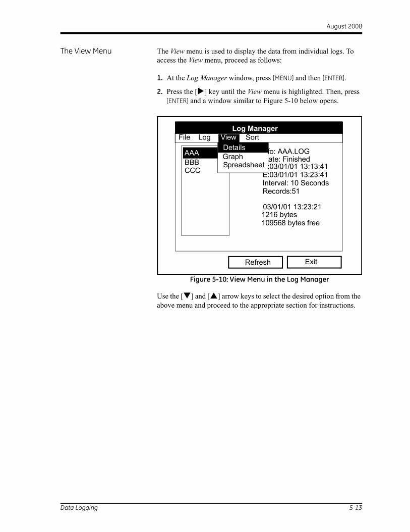
August 2008
The View Menu The View menu is used to display the data from individual logs. To access the View menu, proceed as follows:
1. At the Log Manager window, press [MENU] and then [ENTER].
2. Press the [ ] key until the View menu is highlighted. Then, press [ENTER] and a window similar to Figure 5-10 below opens.
Figure 5-10: View Menu in the Log Manager
Use the [ ] and [ ] arrow keys to select the desired option from the above menu and proceed to the appropriate section for instructions.
Log Manager
Info: AAA.LOG
03/01/01 13:23:211216 bytes109568 bytes free
Exit
AAABBBCCC
State: FinishedS:03/01/01 13:13:41E:03/01/01 13:23:41Interval: 10 SecondsRecords:51
GraphSpreadsheet
DetailsFile Log View Sort
Refresh
Data Logging 5-13

August 2008
The Details Option Use the Details option to view the log data in text format:
1. In the Log Manager window (see Figure 5-2 on page 5-2), use the [ ] and [ ] arrow keys to highlight the log you wish to view.
2. At the Log Manager window, press [MENU] and then [ENTER].
3. Press the [ ] key twice to highlight the View menu and press [ENTER].
4. In the View menu, scroll to the Details option and press [ENTER]. A window similar to Figure 5-11 below opens.
Figure 5-11: The Log Info Window
Note: The actual records (data points) for the log will be listed in the box above.
5. When you have finished viewing the log data, press [F3] (Exit) to return to the Log Manager window.
Log InfoState: FinishedS:03/01/01 13:13:41E:03/01/01 13:23:41Interval:10 SecondsRecords:51Precision: 8 Error:No (Basic)
Velocity: Meters/sec
Exit
5-14 Data Logging

August 2008
The Graph Option Use the Graph option to view the log data in graphical format:
1. In the Log Manager window (see Figure 5-2 on page 5-2), use the [ ] and [ ] arrow keys to highlight the log you wish to view.
2. At the Log Manager window, press [MENU] and then [ENTER].
3. Press the [ ] key twice to highlight the View menu and press [ENTER].
4. In the View menu, scroll to the Graph option and press [ENTER]. This opens the Select Measurement window (see Figure 5-7 on page 5-6), which lists the log measurement parameters.
5. If the log contains more than one measurement, scroll through the list to highlight the parameter you wish to graph. Then, press [F3] (View) and a window similar to Figure 5-12 below appears.
Figure 5-12: The Log Graph Window
The following choices are now available:
• Press [F1] (Scale) if you wish to change the y-axis limits.
• Press [F2] (Time) if you wish to change the x-axis limits.
• Press [F3] (Exit) when you have finished viewing the graph.
AAA.LOG (Velocity, ft/s)
297
Time Exit
2001/03/01 2001/03/01 13:23:41 PM 13:53:41 PM
289
Scale
Data Logging 5-15

August 2008
The Spreadsheet Option Use the Spreadsheet option to view the log data in spreadsheet format:
1. In the Log Manager window (see Figure 5-2 on page 5-2), use the [ ] and [ ] arrow keys to highlight the log you wish to view.
2. At the Log Manager window, press [MENU] and then [ENTER].
3. Press the [ ] key twice to highlight the View menu and press [ENTER].
4. In the View menu, scroll to the Spreadsheet option and press [ENTER]. A window similar to Figure 5-13 below appears.
Figure 5-13: The Log Spreadsheet Window
5. To view the data points, use the four arrow keys to scroll through the cells in the spreadsheet. At any time, you may select one of the following options:
• Press [F1] (Time) to display data from different times in the log.
• Press [F2] (Refresh) to update the window with the most current data.
• Press [F3] (Exit) when you have finished viewing the data.
Refresh Exit
123.LOG
Time03/20/200114:24:4614:24:5614:25:0614:25:17
14:25:2714:25:37
14:25:47
Diagnostics P# Up
450448451
453450
449
Time
5-16 Data Logging

Appendix A

Menu Maps
Main Menu . . . . . . . . . . . . . . . . . . . . . . . . . . . . . . . . . . . . . . . . . . . . . . . . . . . . . A-1

August 2008
A-1
Meter Service
SiteFile Sort
Site Program Logging
MAIN MENU
"Grayed Out" menus are not discussed in this abridged manual. See your full PT878 User's Manual.
Manager
Save Message
File View SortLog
Log Manager
New Log
Spreadsheet
Details
Graph
Start All
End All
View All
Pause All
End
Pause
Start
Transfer
Delete
Delete All
Rename
Clone Log
New
Print All
Pipe
Transducer
Totals
ser Tables
Snapshot
Units
Backlight
Language
munications
Contrast
Locale
Date/Time
Battery
Figu
re A
-1: M
ain
Men
u
Menu Maps
Clear F3
Clear F2
Clear F1
F3
F2
F1Fkeys
Drive Manager
4 Views
3 Views
2 Views
Delete
Save
Open
Rename
Refresh
Save As
New
Transfer As Text
Transfer
Digital Output
User Functions
Correction Factors
Analog Output
Analog Input
Energy
Path
Fluid
U
Com
1 View Print Lining

GESensing & Inspection Technologies
DECLARATIONOF
CONFORMITY
CERT-DOC-H5 August 2004
TÜV ESSENISO 9001
U.S.
TÜV
We, GE Sensing 1100 Technology Park Drive
Billerica, MA 01821 U.S.A.
declare under our sole responsibility that the
TransPort® PT878 Portable Liquid Ultrasonic FlowmeterTransPort® PT878GC Clamp-On Portable Liquid Ultrasonic Flowmeter
to which this declaration relates, are in conformity with the following standards:
• EN 61326:1998, Class A, Annex C, Continuous Unmonitored Operation
following the provisions of the 89/336/EEC EMC Directive.
The units listed above and any transducers supplied with them (spoolpieces are addressed under a separate declaration of conformity) do not bear CE marking for the Pressure Equipment Directive, as they are supplied in accordance with Article 3, Section 3 (sound engineering practices and codes of good workmanship) of the Pressure Equipment Directive 97/23/EC for DN<25.
November 14, 2007Date of Issue Mr. Gary Kozinski
Certification & Standards, Lead Engineer

USA
1100 Technology Park DriveBillerica, MA 01821-4111Web: www.gesensing.com
Ireland
Sensing HouseShannon Free Zone EastShannon, County Clare