datasheet 25-25 flowmeter - Deltafluid
11
Contents Specifications……………………………………………………………………………… page 2 Assembly…………………………………………………………………………………… page 3 Drawings…………………………………………………………………………………….. page 4 Complete 25/25 flowmeter…….……………………………………………………………….. page 5 Ordering information………………………………………………………………………. page 7 Upstream and downstream straight lengths acc. Standards…………………………. page 10 Installation and flowmeter orientation…………………………………………………… page 11 Datasheet Rev.1 Feb 2015 25/25 flowmeter Pre-assembled complete set including orifice plate mounted between orifice flanges Orifice plate design based on ISO5167, BS1042, ASME.MFC.3M or ISO TR15377 :2007 industry standards Accuracy, repeatability and reliability of the flow element No need of calibration Easy and quick installation and commissioning Very long life-time product Robust, cost-effective and maintenance- free system Opportunity to manufacture a complete flowmeter including up and downstream lengths, temperature sensor & multi- variable transmitter
-
Upload
khangminh22 -
Category
Documents
-
view
1 -
download
0
Transcript of datasheet 25-25 flowmeter - Deltafluid

Contents Specifications……………………………………………………………………………… page 2 Assembly…………………………………………………………………………………… page 3 Drawings…………………………………………………………………………………….. page 4 Complete 25/25 flowmeter…….……………………………………………………………….. page 5 Ordering information………………………………………………………………………. page 7 Upstream and downstream straight lengths acc. Standards…………………………. page 10 Installation and flowmeter orientation…………………………………………………… page 11
Datasheet Rev.1 Feb 2015
25/25 flowmeter
Pre-assembled complete set including orifice plate mounted between orifice flanges
Orifice plate design based on ISO5167,
BS1042, ASME.MFC.3M or ISO TR15377 :2007 industry standards
Accuracy, repeatability and reliability of the flow element
No need of calibration
Easy and quick installation and commissioning
Very long life-time product Robust, cost-effective and maintenance-
free system Opportunity to manufacture a complete
flowmeter including up and downstream lengths, temperature sensor & multi-variable transmitter

25-25 flowmeter – Rev.1 Feb 2015 - Page 2
Specifications
Applications - standards Standards ISO5167, BS1042, ASME.MFC.3M, ISO
TR15377 :2007 Fluid temperature -110°C to +800°C Type of fluid Gas, steam, liquid (single-phase fluids) Nominal diameters ND50 to ND1000 according ISO5167-1
(from 2 up to 40 inches) ND15 up to ND50 according ISO TR 15377 :2007 (from 1/2 up to 2 inches)
Maximum operating pressure
Limited by the flange rating
Features Ratio pressure loss 42% to 95% of ∆P(1) Accuracy <1% to 2,5% depending on the installation Material orifice plate Stainless steel, Inconel, Monel, Hastelloy, PTFE, Duplex,
Superduplex, Titanium, Tantalum, PVC, etc Type of orifice flanges Welding neck, slip-on… Type of pressure taps Taps located in the flanges : high pressure tap is 25.4 mm (1
inch) upstream of the inlet face and the low tap is the same distance downstream of the outlet face of the orifice plate
Material orifice flanges Stainless steel, Carbon steel, Inconel, Monel, Hastelloy, PTFE, Duplex, Superduplex, etc
Type of gaskets Flat seal (spiral wound gasket, graphite, PTFE) or RTJ (mild steel, stainless steel, monel alloy…)
(1) Depending on the type of orifice plate and on the ß value – see relevant datasheet for details Mounting Piping connection 25/25 flowmeter mounted between straight sections (variable
lengths regarding β and obstacles located up and downstream – see table 1 here-after)
Centering of orifice bore relative to piping
Distance e between the centerline of the orifice and the centerline of the pipe in the direction parallel to the pressure tapping : e ≤ 0,002 5D / (0,1 + 2,3 β4)
Process connection Pipes with flanges (RF or RTJ) or butt welding Limits of use Flange taps d ≥ 12.5 mm
0.1 ≤ β ≤ 0.75 ReD ≥ 5000 & ReD ≥ 170 β² D
Integrated 25/25 pressure taps on the flanges are widely used as a 25/25 flowmeter

25-25 flowmeter – Rev.1 Feb 2015 - Page 3
Assembly
Orifice plate between Welding-Neck flanges with 25/25 pressure taps (1 inch/1 inch)
Orifice plate
Gasket
WN Flange
Bolting

25-25 flowmeter – Rev.1 Feb 2015 - Page 4
Drawings
Orifice plate between Welding-Neck flanges Orifice plate between Slip-On flanges with 25/25 pressure taps (1 inch/1 inch) with 25/25 pressure taps (1 inch/1 inch)
RTJ male orifice plate between Welding-neck flanges with 25/25 pressure taps (1 inch/1 inch)
The orifice plate is placed in the RTJ (ring tongue joint) orifice carrier. Made of a soft material, the RTJ orifice carrier is to be mounted between RTJ flanges and is used to ensure proper sealing. The set orifice place and orifice carrier can also be made of a single piece material.
RTJ female orifice plate
RTJ male orifice plate

25-25 flowmeter – Rev.1 Feb 2015 - Page 5
Complete 25/25 flowmeter including up and downstream lengths, temperature sensor & multi-variable
transmitter
Installation requirements Pipe alignment Straight pipe if deviation from a straight line
< 0,4% over its length Upstream pipe roughness Ra to be respected on a length ≥10D
See diagram here under See ISO5167-2 standard
Circularity of the upstream pipe D ≤ D ± 0,3% D on a length ≤ 2D Circularity of the downstream pipe D ≤ D ± 3% D on a length ≤ 2D Temperature sensor location On the downstream pipe, distance between
the temperature sensor and the primary device between 5D and 15D
Diagram : Roughness and cylindricality criterion

25-25 flowmeter – Rev.1 Feb 2015 - Page 6
Examples of assemby
Photo 1 : 25/25 flowmeter with orifice welding neck flanges, upstream and downstream required straight lengths, temperature sensor, remote manifold and differential pressure multivariable transmitter.
Photo 2 : 25/25 flowmeter with orifice flanges, upstream and downstream required straight lengths, temperature sensor, direct mounted manifold and differential pressure multivariable transmitter
Photo 3 : 25/25 flowmeter with orifice flanges, upstream and downstream pipes, direct mounted manifold and differential pressure transmitter

25-25 flowmeter – Rev.1 Feb 2015 - Page 7
Ordering information – MAIN CODE
Delta 25/25 - 25/25 flowmeter XX XXX X XX XX XXX XXXXX XXX XX XXX XXX X XXType of upstream face Sharp Edge SEConical Entrance COQuarter Circle QCEccentric ECSegmental SGMulti holes MHType of faceRaising Face RF*(1)
Ring Torque Joint RTJ for RTJ : Male M Female F in 1 piece or in 2 pieces Monobloc MO Screwed*(2) SCType of finishingPolished 1 face PPolished 2 faces 2POthers - SPECIFY ONominal diameterDN15 - 1/2'' 1DN20 - 3/4'' 0,75DN25 - 1'' 1DN32 - 1''1/4 1,25DN40 - 1''1/2 1,5DN50 -2'' 2DN65 - 2''1/2 2,5DN80 - 3'' 3DN100 - 4'' 4DN125 - 5'' 5DN150 - 6'' 6DN200 - 8'' 8DN250 - 10'' 10DN300 - 12'' 12DN350 - 14'' 14DN400 - 16'' 16DN450 - 18'' 18DN500 - 20'' 20DN600 - 24'' 24Rating150# A150300# A300600# A600900# A9001500# A15002500# A2500PN10 D10PN16 D16PN25 D25PN40 D40PN63 D63PN100 D100
MAIN CODE

25-25 flowmeter – Rev.1 Feb 2015 - Page 8
Delta 25/25 - 25/25 flowmeter XX XXX X XX XX XXX XXXXX XXX XX XXX XXX X XXPlate materialStainless steel 304 SS4Stainless steel 316 SS6Inconel INCMonel MONHastelloy HLYPTFE PTFDuplex DPXSuperduplex SDXOthers - SPECIFY OOrifice flangesWelding neck WNSlip on SOOthers OFlanges materialASTM A105 105A350LF2 350Carbon steel*(3) CSTStainless steel 304 SS4Stainless steel 316 SS6Inconel INCMonel MONHastelloy HLYPTFE PTFDuplex DPXSuperduplex SDXOther OPipe Schedule5-5S 510-10S 1020 2030 3040S-Std STD40 4060 60XS-80S XS80 80100 100120 120140 140160 160XXS XXSGasketsFlat FGraphite GSpiral wound SPTFE POthers OBoltings materialCarbon steel CSStainless steel SSOthers O
*(1) OP-XX-RF can be assembled with simple or double & male or female facing depending on the flange*(2) Plate support material to be specified*(3) Type of carbon steel to be specified
MAIN CODE

25-25 flowmeter – Rev.1 Feb 2015 - Page 9
Ordering information – OPTIONS OPTIONAL CODE XX XX X XManifold3-way direct mounting 3D3-way remote mounting 3R5-way direct mounting 5D5-way remote mounting 5RDP TransmitterStandard SDMultivariable MVTemperature sensor*(1)
With temperature sensor YWithout temperature sensor NPiping*(2)
Upstream UDownstream D
*(1) Type of temperature sensor to be specified*(2) Process connection to be specified

25/25 flowmeter – Rev. 1 Feb 2015 – Page 10
Dia
met
er
ratio
d/D
UPSTREAM SIDE OF PRIMARY ELEMENT
DOWN STREAM
OF PRIMARY ELEMENT
β single 90° bend
or two 90° bends in any plane (S>30D)
Two 90° bends in the same plane:
S-config. 30D>S>10D
Two 90° bends in the same plane:
S-config. 10D>S
Two 90° bends in perpen-
dicular planes 30D>S>5D
Two 90° bends in perpen-
dicular planes 5D>S
Simple 90° tee with or without an extension
Simple 45° bend or 2
bends in the same plane :
S-config (S>2D)
Concentric reducer 2D to D over a
length of 1,5D to 3D
Concentric expander 0,5D to D
over a length D to 2D
Full bore ball valve or gate
valve fully open
Abrupt symetrical reduction
Thermometer pocket or
well of Ø < 0,03 D
Fittings (columns 2 to 11) and
the densitometer
1 2 3 4 5 6 7 8 9 10 11 12 13 12
<0,2 6 3 10 10 19 18 34 17 3 7 5 6 12 6 30 15 5 3 4 2
0,40 16 3 10 10 44 18 50 25 9 3 30 5 12 8 12 6 30 15 5 3 6 3
0,50 22 9 18 10 22 10 44 18 75 34 19 9 30 18 8 5 20 9 12 6 30 15 5 3 6 3
0,60 42 13 30 18 42 18 44 18 65 25 29 18 30 18 9 5 26 11 14 7 30 15 5 3 7 3,5
0,67 44 20 44 18 44 20 44 20 60 18 36 18 44 18 12 6 28 14 18 9 30 15 5 3 7 3,5
0,75 44 20 44 18 44 22 44 20 75 18 44 18 44 18 13 8 36 18 24 12 30 15 5 3 8 4
Table 1 - Straight lengths Required straight lengths between orifice plates and fittings – without flow conditioners
Notes: The minimum straight lengths required are the lengths between various fittings located upstream and downstream of the orifice plate and the orifice plate itself. Straight lengths shall be measured from the upstream face of the orifice plate. First column for each fitting gives lengths corresponding to « zero additional uncertainty » values (cf standard ISO 5167.1) Second column for each fitting gives lengths corresponding to “0,5% additional uncertainty” values (cf standard ISO 5167.1). S represents the distance between two accessories
Values expressed as multiples of internal diameter, D
25/25 flowmeter – Rev. 1 Feb 2015 – Page 11
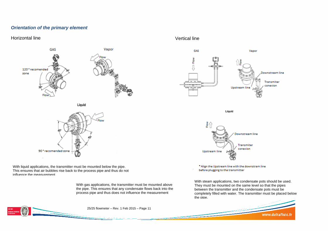
Orientation of the primary element Horizontal line
Vertical line
With liquid applications, the transmitter must be mounted below the pipe. This ensures that air bubbles rise back to the process pipe and thus do not influence the measurement.
With gas applications, the transmitter must be mounted above the pipe. This ensures that any condensate flows back into the process pipe and thus does not influence the measurement
With steam applications, two condensate pots should be used. They must be mounted on the same level so that the pipes between the transmitter and the condensate pots must be completely filled with water. The transmitter must be placed below the pipe.