ULTRASONIC SONAR CONTROLLED ACTIVE SUSPENSION ...
63
Outer Ring Road, Marathahalli, Bengaluru-560103 ULTRASONIC SONAR CONTROLLED ACTIVE SUSPENSION SYSTEM USING ARDUINO PROJECT WORK [AUT84] Submitted by DIVYA TEJA T (1NH16AU011) JOJI JOHN (1NH16AU018) VIBIN J GERALD (1NH16AU057) VIKRANTH S SAOOR (1NH16AU059) In partial fulfilment for the award of the degree of BACHELOR OF ENGINEERING IN AUTOMOBILE ENGINEERING Under The Guidance of Dr. Shridhar Kurse HOD, Department of Automobile. Department of Automobile Engineering, NHCE August, 2020
-
Upload
khangminh22 -
Category
Documents
-
view
3 -
download
0
Transcript of ULTRASONIC SONAR CONTROLLED ACTIVE SUSPENSION ...
Outer Ring Road, Marathahalli, Bengaluru-560103
ULTRASONIC SONAR CONTROLLED ACTIVE SUSPENSION
SYSTEM USING ARDUINO
PROJECT WORK [AUT84]
Submitted by
DIVYA TEJA T (1NH16AU011)
JOJI JOHN (1NH16AU018)
VIBIN J GERALD (1NH16AU057)
VIKRANTH S SAOOR (1NH16AU059)
In partial fulfilment for the award of the degree of
BACHELOR OF ENGINEERING
IN
AUTOMOBILE ENGINEERING
Under The Guidance of
Dr. Shridhar Kurse
HOD, Department of Automobile.
Department of Automobile Engineering, NHCE
August, 2020

Outer Ring Road, Marathahalli, Bengaluru-560103
DEPARTMENT OF AUTOMOBILE ENGINEERING
CERTIFICATE
This is to certify that the Project Work [AUT84]
On
“ULTRASONIC SONAR CONTROLLED ACTIVE SUSPENSION SYSTEM USING ARDUINO”
Is a bonafide work carried out by
Divya Teja T [1NH16AU011]
Joji John [1NH16AU018]
Vibin J Gerald [1NH16AU057]
Vikranth S Saoor [1NH16AU059]
In partial fulfilment for the award of degree of Bachelor of Engineering in
Automobile Engineering of the Visvesvaraya Technological university,
Belgaum during Even Semester, 2019-20. It is certified that all
corrections/suggestions indicated for internal assessment has been
incorporated in the report deposited in the department library.
The project report has been approved as it satisfies the academic
requirements in respect of Project Work prescribed for the said Degree.
Signature of Internal Guide
Dr. Shridhar Kurse
Signature of HOD Dr. Shridhar Kurse
Signature of Principal Dr. Manjunatha
External Viva
Name of the Examiners
1. 2.
Signature with Date

ACKNOWLEDGEMENT
We express our heartfelt thanks to Dr. Mohan Manghnani, Chairman, New Horizon
Educational Institutions for providing this endower.
We would also like to thank Dr. Shridhar Kurse, HOD, Automobile Dept, NHCE and Dr.
Manjunatha, Principal of NHCE who has given us a constant support with motivation in
completion of the mini project.
We sincerely thank, Dr. Shridhar Kurse, HOD, Department of Automobile Engineering, NHCE
who has guided us throughout in completion of the mini project.
We thank entire staff members of Automobile Department, NHCE and everyone who has
directly or indirectly helped us in completion of the mini project.
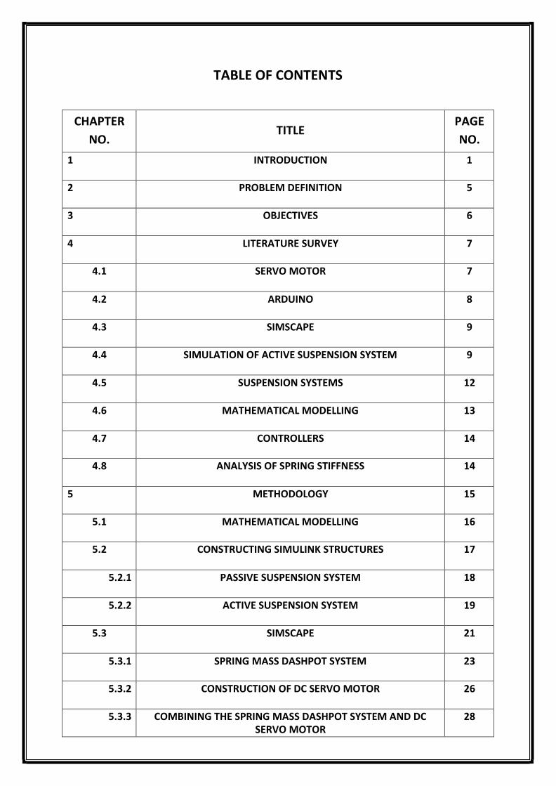
TABLE OF CONTENTS
CHAPTER
NO. TITLE
PAGE
NO.
1 INTRODUCTION 1
2 PROBLEM DEFINITION 5
3 OBJECTIVES 6
4 LITERATURE SURVEY 7
4.1 SERVO MOTOR 7
4.2 ARDUINO 8
4.3 SIMSCAPE 9
4.4 SIMULATION OF ACTIVE SUSPENSION SYSTEM 9
4.5 SUSPENSION SYSTEMS 12
4.6 MATHEMATICAL MODELLING 13
4.7 CONTROLLERS 14
4.8 ANALYSIS OF SPRING STIFFNESS 14
5 METHODOLOGY 15
5.1 MATHEMATICAL MODELLING 16
5.2 CONSTRUCTING SIMULINK STRUCTURES 17
5.2.1 PASSIVE SUSPENSION SYSTEM 18
5.2.2 ACTIVE SUSPENSION SYSTEM 19
5.3 SIMSCAPE 21
5.3.1 SPRING MASS DASHPOT SYSTEM 23
5.3.2 CONSTRUCTION OF DC SERVO MOTOR 26
5.3.3 COMBINING THE SPRING MASS DASHPOT SYSTEM AND DC SERVO MOTOR
28

5.4 TESTING THE ACTIVE SUSPENSION RIG IN SIMULINK 29
5.5 ELECTRONIC COMPONENTS 38
5.6 SETTING UP THE SENSOR AND ACTUATOR TO THE ARDUINO 43
5.6.1 CONFIGURATION OF THE PROGRAM FOR THE ARDUINO BOARD 43
5.6.2 THE CODE 45
5.7 LINKAGES 48
6 CONCLUSION 52
REFERENCES 53
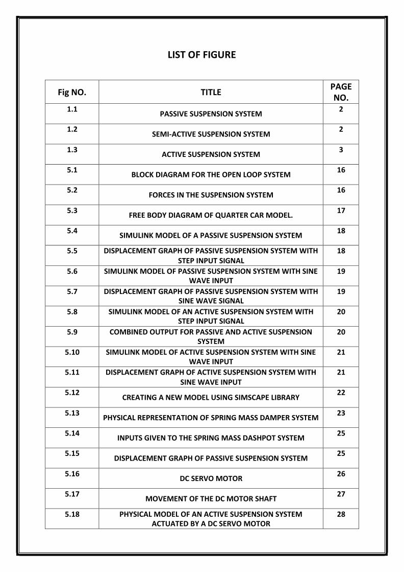
LIST OF FIGURE
Fig NO. TITLE PAGE NO.
1.1 PASSIVE SUSPENSION SYSTEM
2
1.2 SEMI-ACTIVE SUSPENSION SYSTEM
2
1.3 ACTIVE SUSPENSION SYSTEM
3
5.1 BLOCK DIAGRAM FOR THE OPEN LOOP SYSTEM
16
5.2 FORCES IN THE SUSPENSION SYSTEM
16
5.3 FREE BODY DIAGRAM OF QUARTER CAR MODEL.
17
5.4 SIMULINK MODEL OF A PASSIVE SUSPENSION SYSTEM
18
5.5 DISPLACEMENT GRAPH OF PASSIVE SUSPENSION SYSTEM WITH STEP INPUT SIGNAL
18
5.6 SIMULINK MODEL OF PASSIVE SUSPENSION SYSTEM WITH SINE WAVE INPUT
19
5.7 DISPLACEMENT GRAPH OF PASSIVE SUSPENSION SYSTEM WITH SINE WAVE SIGNAL
19
5.8 SIMULINK MODEL OF AN ACTIVE SUSPENSION SYSTEM WITH STEP INPUT SIGNAL
20
5.9 COMBINED OUTPUT FOR PASSIVE AND ACTIVE SUSPENSION SYSTEM
20
5.10 SIMULINK MODEL OF ACTIVE SUSPENSION SYSTEM WITH SINE WAVE INPUT
21
5.11 DISPLACEMENT GRAPH OF ACTIVE SUSPENSION SYSTEM WITH SINE WAVE INPUT
21
5.12 CREATING A NEW MODEL USING SIMSCAPE LIBRARY
22
5.13 PHYSICAL REPRESENTATION OF SPRING MASS DAMPER SYSTEM
23
5.14 INPUTS GIVEN TO THE SPRING MASS DASHPOT SYSTEM
25
5.15 DISPLACEMENT GRAPH OF PASSIVE SUSPENSION SYSTEM
25
5.16 DC SERVO MOTOR
26
5.17 MOVEMENT OF THE DC MOTOR SHAFT
27
5.18 PHYSICAL MODEL OF AN ACTIVE SUSPENSION SYSTEM ACTUATED BY A DC SERVO MOTOR
28
5.19 DISPLACEMENT GRAPH OF ACTIVE SUSPENSION SYSTEM
29
5.20 ARDUINO HARDWARE SUPPORT PACKAGE PAGE IN MATLAB
30
5.21 SUPPORT PACKAGE LIBRARY
30
5.22 ULTRASONIC SENSOR BLOCK
31
5.23 DIALGUE BOX FOR PIN CONNECTIONS
31
5.24 BLOCK PARAMETERS DIALOGUE BOX
32
5.25 DATA TYPE CONVERSION DIALGUE BOX
32
5.26 BLOCK PARAMETERS: GAIN
33
5.27 COMPLETE SIMULINK MODEL
33
5.28 MATLAB COMMAND WINDOW
34
5.29 CONFIGURATION SETTINGS
34
5.30 THE SOFTWARE PREPARING TO SEND THE MODEL TO THE ARDUINO
35
5.31 OUTPUT RESPONSE GRAPH
35
5.32 VEHICLE APPROACHING POTHOLE
36
5.33 OUTPUT REACTION PRODUCED IN THE GRAPH
37
5.34 VEHICLE APPROACHING BUMP ON ROAD
37
5.35 SECOND CASE OUTPUT REACTION SEEN IN THE GRAPH
38
5.36 ULTRASONIC SENSOR MODULE
39
5.37 ARDUINO UNO BOARD
40
5.38 METAL GEAR SERVO
41
5.39 CROSS SECTIONAL VIEW OF SERVO MOTOR
42
5.40 SERVO MOTOR WORKING METHODOLOGY
42
5.41 CONNECTED VIEW OF THE COMPONENTS
43
5.42 ARDUINO IDE SKETCH PAGE
44

5.43 CODE WRITTEN IN ARDUINO IDE
45
5.44 STATUS OF CODE COMPILATION AND UPLOAD MESSAGE SHOWN IN THE ARDUNIO IDE
46
5.45 OUTPUT OF DISTANCE RECORDED SEEN ON THE SERIAL MONITOR
47
5.46 ULTRASONIC SENSOR SIGNAL PROJECTION
47
5.47 SERVO MOTOR ROTATION
47
5.48 CONVENTIONAL DOUBLE WISHBONE SUSPENSION
48
5.49 DETAILED VIEW OF DOUBLE-WISHBONE SUSPENSION
49
5.50 THEORETICAL SKETCH FOR DESIGNED SYSTEM
50
5.51 PROTOTYPE MODEL LINKAGE TEST
50
5.52 CYLINDER RETRACTED
51
5.53 CYLINDER EXTENDED
51
Abstract
Suspension systems are important part of the automobile that provides riding comfort, road
grip and minimises the vibrations transferred from the road input. The system has been
subjected to advancements and improvisation with the help of technology, making it a
smarter suspension. In this project, an alternative design for the same was created using a
LIDAR/Sonar sensor, an Arduino unit and a servo motor actuator. The model theoretically
tested in the MATLAB tool by feeding the mathematical model and the output was
represented in a graphical format comparing the outputs for both active and passive
systems.

ULTRASONIC SONAR CONTROLLED ACTIVE SUSPENSION SYSTEM USING ARDUINO
DEPARTMENT OF AUTOMOBILE ENGINEERING Page 1
Chapter 1
Introduction
Introduction to suspension system
The suspension system is the link between the main body and the wheels which allows a
relative motion between them. The components that form a complete suspension
system are the coil springs, dampers or shock absorbers, strut assembly and torsion bar.
The primary functions of the suspension system are to provide ride quality and tractive
effect, in parallel the system also protects the vehicle or the cargo from wear. The most
significant function is to provide the comfortable drive to the passengers while travelling
in all the types of terrain and to ensure terrain grip at all circumstances.
As the vehicle travels over an irregularity in the road, there is energy produced in the
form of vibrations and are absorbed by the spring and in turn dissipated by the dampers.
The vibrations are transferred all the way up to the chassis and realised by the passenger
only when the components undergo ultimate wear. Most of the suspension systems use
the conventional springs and dampers as the passive system, where as there are
exceptions made in case of hydro-pneumatic systems as they use an integrated unit of
gas springs and dampers.
There are three types of suspension system
Passive suspension system
Semi-Active suspension system
Active suspension system
Passive suspension system
All the vehicles in the past and few in the present years incorporate the passive
suspension system. This system uses the conventional spring and damper elements as
their only components. It has derived its name as it is unable to provide energy to the
system or allows passing a feedback to the system. The system achieves its riding
comfort by reducing the velocity of the relative motion between the wheel and main
body assembly. Over the years, the passive systems were optimised based on the

ULTRASONIC SONAR CONTROLLED ACTIVE SUSPENSION SYSTEM USING ARDUINO
DEPARTMENT OF AUTOMOBILE ENGINEERING Page 2
advancement of technology and its adaptation based on the type of vehicle and the
terrain. K1 & k2= spring stiffness; b1 & b2 = damper coefficients
Fig. 1.1 Passive suspension system.
Semi-Active suspension system
An improvised version of the passive suspension system that requires much less energy
to function and it is cheaper comparatively than the old passive suspension system.
These systems obtain a higher damping force by incorporating the use of magneto-
rheological dampers (MR dampers). The only possible alteration that can be processed
on the system is done by changing the value of damping coefficients. However, this
system carries one of the major limitations as the passive system and that is the
disability to provide energy to the system.
Fig. 1.2 Semi-Active suspension system.

ULTRASONIC SONAR CONTROLLED ACTIVE SUSPENSION SYSTEM USING ARDUINO
DEPARTMENT OF AUTOMOBILE ENGINEERING Page 3
Active suspension system
In this type of suspension system, the vertical height of the suspension system is
adjusted by obtaining feedback about the obstacles or irregularities on the road surface.
This system comprises of a controller, sensor and an actuator acting as a unit. The
signals from the sensors are passed to the controller, the controller being computer
aided to command the actuator to expand and shrink the height of the suspension
system. This kind of advancement in the technology allows the manufacturers to build a
suspension system that achieves ultimate drive quality, comfort, tractive effect, stability
and manoeuvrability.
Fig. 1.3 Active suspension system.
Introduction to Arduino Uno
Arduino Uno is a programmable microcontroller with a set of both digital and analog
input/output (I/O). It has 14 digital pins and 6 analog pins for input/output and can
be programmed with Arduino Integrated Development Environment (Arduino IDE).
The Arduino board being user friendly without major complications finds its
application in the field of robotics, AI based projects and is also used to build and
create new devices. There are various types Arduino boards available in the market
and among them Arduino Uno is a standard variant and is generally preferred. The
microcontroller takes the input from the electronic devices and allows the user to
control the outputs from the same.

ULTRASONIC SONAR CONTROLLED ACTIVE SUSPENSION SYSTEM USING ARDUINO
DEPARTMENT OF AUTOMOBILE ENGINEERING Page 4
Introduction to Servo Motors
The servo motor is a type of an actuator that allows rotary or linear actuation and
provides ultimate control over its angular or linear positions, acceleration and its
velocity. It takes the feedback about its position from a sensor that is couples to the
motor. The operation of the servo motor is generally controlled by a controller
module designed specifically for the application. There are multiple classifications
among the servo motors based on their application like AC servo motor, DC servo
motor, continuous rotation type, linear movement type, etc. A servo motor acts as a
closed loop mechanism as it takes feedback about its position to control its own
motion. Apart from the main control circuit servo motors incorporate other
subcomponents such as a dc motor, a position sensing device, a reduction gear unit.
The dc servo motors find its application in the field of robotics and machinery and
are classified as prime movers which provide the characteristics to limit the motion
of the device accurately.

ULTRASONIC SONAR CONTROLLED ACTIVE SUSPENSION SYSTEM USING ARDUINO
DEPARTMENT OF AUTOMOBILE ENGINEERING Page 5
Chapter 2
Problem Definition
On a comparative basis the demand for the active suspension system has grown higher
than that of passive suspension system over the recent years. The passive system
consists of an energy dissipating element known as the damper and the energy storing
element known as the spring, but both these elements cannot add energy to the system.
That is the main reason why passive systems are stated unreliable to high frequency
disturbances. This system cannot be altered from time to time and there is no state of
adaptability shown by the system on varying road surfaces. Hence, the passive system
causes issues such as uncomfortable travel and loosening of the tractive effect.
Active suspension in addition provides a force input and thus requires very less energy. It
provides a comfortable drive without even under varying load maintains the level of car
during braking and prevents dip or rise under situations of sudden acceleration and
deceleration. This system gets oriented as per the road conditions providing better
damping of shocks and also, the car ensures stability over harsh bumps and cornering.
Though such advancement in the system has been incorporated, there are certain
limitations about the same. This kind of a system is highly expensive and although the
usage of controller reduces the vibration frequency, there are certain minimal amount
of shocks transferred all the way to the body. Hence, the driver or the passengers do
realise the variation in the driving comfort level.
An alternative model for the was developed. In this system, the variations in the roads
including are predicted by the help of a Lidar/Ultrasonic sensor. The inputs from the
sensor are passed on to a programmed Arduino system and this in turn commands a DC
servo motor that acts as an actuator to adjust the height of the suspension system. With
the use of two springs the shocks transferred to the chassis are reduced to a negligible
frequency. Thus, the limitations caused by the passive suspension system are resolved
and a comfortable travel is obtained. The characteristics mentioned above are attained
by adjusting the values of the spring stiffness of all springs and damping coefficient of
the damper.
ULTRASONIC SONAR CONTROLLED ACTIVE SUSPENSION SYSTEM USING ARDUINO
DEPARTMENT OF AUTOMOBILE ENGINEERING Page 6
Chapter 3
Objectives
The main objectives of this project are:
1. Research about the active suspension systems, sensors, servo motors, spring
stiffness to decide which concept can be used.
2. Discover a way to incorporate the active suspension system into the automobiles in
a lesser expensive way than the existing models.
3. Derive a mathematical model (transfer function) using the dynamics and kinematics
of a free body diagram of the proposed model.
4. Simulate the system in Simulink and Simscape.
5. Write a program in MATLAB to link the Simulink models
6. Simulate the model simscape to see if there are any deviations from the results of
the Simulink model.
7. Compare the output graphs and make the necessary changes, if required, to
improve the quality of the system.
8. Fabricate the proposed model on a small scale basis using sensors, arduino, and
servo motor.
Tools used:
MATLAB/Simulink: MATLAB is an essential software to engineers that allows them to
develop algorithm, simulate, modelling, data analysis, prototyping etc. Simulink is used
to create models and simulate using block diagrams. MATLAB can be used to create
various input data sets in order to simulate the model.
Simscape: Simscape is like Simulink but uses physical modelling approach instead of
block diagram approach.
Arduino: Arduino is an open source program which enables the users to create
electronic objects. It is a prototyping platform related to the electronic components. It
can be programmed various programming languages.

ULTRASONIC SONAR CONTROLLED ACTIVE SUSPENSION SYSTEM USING ARDUINO
DEPARTMENT OF AUTOMOBILE ENGINEERING Page 7
Chapter 4
Literature Survey
4.1 Servo Motor
1. Title: A Matlab/Simulink- Based Interactive Module for Servo System Learning
Author: Nourdine Aliane; Computer Architecture Dept., Univ. Europea de Madrid
(UEM), Madrid, Spain.
Overview
The Fundamental and practical issues of servo system were learnt by an interactive
module. The interactive module is developed with the help of Simulink and Matlab
graphical user interface (Matlab-GUI), is used to study standard lectures in control
engineering and robotics. This paper can be segregated into two parts: Introduction of
the servo systems and interactive module using Simulink and Matlab graphical user
interface (Matlab-GUI).
2. Title: Tuning of PID Controller for DC Servo Motor using Genetic Algorithm.
Author: Bindu R, Mini K. Namboothiripad; Department of Electrical Engineering,
Fr.C. Rodrigues Institute of Technology,(Affiliated to Mumbai University) Vashi, Navimumbai
Overview
Generally PID controllers are used to enhance the performance of the DC servo motor,
however at present majority of the tuning methods are designed to come up with
practical initial values which can be optimized as per the requirement. Hence, the study
of position control of DC motor is important as numerous servomechanisms widely
utilize DC servo motors. This paper determines the optimal parameters of the PID
controller by using an algorithm for flexible and fast tuning of DC servo motor.

ULTRASONIC SONAR CONTROLLED ACTIVE SUSPENSION SYSTEM USING ARDUINO
DEPARTMENT OF AUTOMOBILE ENGINEERING Page 8
3. Title: Design of Pi Controller To Minimize The Speed Error of D.C. Servo Motor
Author: Sanjay Singh; A. K. Pandey, Dipraj;
Overview
The speed error of the DC servo motor is minimized by using PI controller. This paper
determines the transfer function to design the PI controller which is validated using
Matlab/Simulink. Hence, the new design provides us with a simple and effective way to
minimize the speed error of the DC servo motor.
4.2 Arduino
1. Title: Simulation of Fuzzy Logic Control for DC Servo Motor using Arduino based on
Matlab/Simulink. Author: Munadi, M. Amirullah Akbar:2014 International
Conference on Intelligent Autonomous Agents, Networks and Systems
Overview
Proportional integral derivative (PID) controller is extensively used in control engineering
because of its robust performance in varying operating conditions and functional
simplicity. This paper deals with the design of PID controller of the DC servo motor and
implemented it to the Arduino board (Mega 2560) via potentiometer by using an
additional package i.e. Simulink support package for Arduino hardware in
MATLAB/Simulink.
2. Title: Design and Development of Active Suspension System to Avoid Sudden Jerks
Using Arduino
Author: Aditya Mane, Akshay Lunawat, Aniket Kokare and Subham Mahire.
Overview
The main purpose of suspension system is to provide passenger comfort and maintain
constant wheel and road contact without vehicle slipping. The requirements cannot be
achieved using passive suspension system however active suspension system with a

ULTRASONIC SONAR CONTROLLED ACTIVE SUSPENSION SYSTEM USING ARDUINO
DEPARTMENT OF AUTOMOBILE ENGINEERING Page 9
controlling system can attain the requirements. This paper deals with obtaining a control
system for a quarter car model using PID controller having proportional, derivative gain
and integral gain parameters. The mathematical model is obtained by applying the
Newton's Law of Motion and further the design is being simulated using specific
software.
4.3 Simscape
1. Title: Modeling Mass-Spring-Damper System using Simscape.
Author: Abhilash Ingale, Anchal Daga,Rajkumar Naik(Final year B.Tech, Mechanical
Engineering, Government College of Engineering, Amravati
Overview
Development of control systems and test system-level performance is done using
Simscape. Custom mechanical components/models can be created using MATLAB based
Simscape language which contains various libraries. This paper deals with the
mathematical modelling and studying the dynamic behaviour of the spring mass-
dashpot system. The results of the model are used as validation for the Simscape model.
2. Title: Real-Time Simulation of Physical Systems Using Simscape
Author: Steve Miller, MathWorks and Jeff Wendlandt, MathWorks
Overview
Simulation of multi-domain physical system models i.e. mechanical, electrical and
hydraulic requires the combination of parameters such as model complexity, solver
choice, solver timer and real time target. The main objective is to achieve a model-based
design to acquire the benefits of using virtual system before constructing prototypes.
The illustration of using Simscape, SimElectronics and SimHydraulics are being discussed
in this paper. The real-time simulation does not depend up on the real-time hardware
used. Models with both linear and nonlinear elements in the domains like hydraulic,
electrical, pneumatic, thermal and mechanical are developed for real-time simulation.

ULTRASONIC SONAR CONTROLLED ACTIVE SUSPENSION SYSTEM USING ARDUINO
DEPARTMENT OF AUTOMOBILE ENGINEERING Page 10
4.4 Simulation of Active Suspension System
1. Title: Simulation and Analysis of Passive and Active Suspension System Using
Quarter Car Model for Different Road Profile.
Authors: Abdolvahab Agharkakli , Ghobad Shafiei Sabet , Armin Barouz
Department of Mechanical Engineering, Shahrood Branch, Islamic Azad University,
Shahrood, Iran
Overview
The main aim of this paper is to develop a mathematical model for the passive and
active suspension system for a quarter car model. Vehicle suspensions are meant to
provide good road handling and improve the comfort of the passengers. Passive
suspension system doesn't fulfil these two factors whereas active suspension system
improves the handling and comfort by controlling the actuators present in the
suspension system. There are various methods to determine the mathematical model;
however this paper uses linear quadratic method (LQR) to obtain the model of the active
suspension system for the quarter car model. Different road profiles are chose in order
to compare between the passive and active suspension system.
2. Title: Research and Simulation on New Active Suspension System
Author: Qi Zhou, Lehigh University
Overview
Suspension systems are the most significant part when it comes to ride quality, good
road handling and passenger comfort. Passive suspension system are not able achieve
these hence the use of active suspension system is considered. This paper deals with the
new control approaches: new algorithm and proportional integrative derivative (PID)
controller which improves the performance of the active suspension system, also the
developed model is simulated using the MATLAB/Simulink with different input signals
like the step input, sine wave input and chirp signal.
ULTRASONIC SONAR CONTROLLED ACTIVE SUSPENSION SYSTEM USING ARDUINO
DEPARTMENT OF AUTOMOBILE ENGINEERING Page 11
3. Title: Passive Suspension Modelling using Matlab, Quarter car model, input signal
step input.
Author: Andronic Florin , Manolache-Rusu Ioan-Cozmin , Pătuleanu Liliana
Overview
The simulation and handling of performance of the passive suspension system having 2
degrees of freedom (DOF) is being discussed in this paper. Since the equations of the
system cannot be solved mathematically, Matlab Simulink is used to analyse the
behaviour of the system.
4. Title: Performance Evaluation of Active Suspension for Passenger Cars Using
MATLAB.
Authors: K. S. Patil , Vaibhav Jagtap , Shrikant Jadhav , Amit Bhosale, Bhagwat Kedar
(Department of Mechanical Engineering, Sree Chatrapati Shivaji College of Engineering,
Pune, India)
Overview
This paper deals with the development of the mathematical model of a quarter car
model having two degrees of freedom (DOF) and examined using MATLAB in order to
improve ride performance, handling and passenger comfort. Proportional Integrative
Derivative (PID) controller is used to evaluate the results of the passive and active
suspension system.
5. Title: Comparison of passive and semi-active suspension system by MATLAB
SIMULINK for different road profiles.
Author: T. P. Phalke, A. C. Mitra Mechanical Engineering, M.E.S. College of Engineering,
Pune, S. P. Pune University, India
Overview
Suspension systems are fully responsible for the ride comfort and performance of the
vehicle. Thereby the design of a suspension system is very essential to achieve these two

ULTRASONIC SONAR CONTROLLED ACTIVE SUSPENSION SYSTEM USING ARDUINO
DEPARTMENT OF AUTOMOBILE ENGINEERING Page 12
factors, thus this paper compares the results between the passive and active suspension
system with three types of inputs i.e. step input, sine wave and chirp signal. These two
factors cannot be achieved by using passive suspension system however semi-active
suspension including the PID (Proportional Integrative Derivative) controller can
accomplish the ride comfort and performance.
6. Title: Simulating passive suspension on an uneven track surface
Author: Florin andronic , Ioan mihai ,Ioan-cozmin manolache-rusu1 , Liliana Pătuleanu1 ,
Ivan radion1 1 Stefan cel Mare University, Universitatii 13, 720229 Suceava, Romania
Overview
Vehicle suspension system plays an important role in the vehicles functioning, mainly
the driving safety. This paper exhibits the equation that specifies a passive suspension
system. The developed equations of the system are simulated on MATLAB/ Simulink
analysing the behaviour and performance of the passive suspension system on any
uneven track surface. Quarter car model is used for the simulation having two degrees
of freedom.
4.5 Suspension systems
1. Title: Development of a New Automotive Active Suspension System
Author: Eng. Yousef Abdulhammed1,a and Prof. Dr Eng. Hisham Elsherif2,b 1German
University in Cairo, Mechatronics Engineering Department, Cairo, Egypt 2German University
in Cairo, Head of Industrial Automation Department, Cairo, Egypt
Overview
A smart new vehicle suspension is developed which minimizes the road irregularities
impact on the driver and also enhance the performance, stability of the vehicle at higher
speeds. The main concept of this paper is by replacing the passive suspension system to
an active suspension system which is computer controlled with the help of actuators and
sensors. The component has been tested on a simulator with various parameters.

ULTRASONIC SONAR CONTROLLED ACTIVE SUSPENSION SYSTEM USING ARDUINO
DEPARTMENT OF AUTOMOBILE ENGINEERING Page 13
The main objectives of this paper are as follows:
Economical
Increase the aerodynamics coefficients
Full stability, steering and fuel economy
2. Title: Optimal Active Suspension structures for Quarter car vehicle models.
Author: D.Hrovat, Research Staff, Ford Motor Company, P.O. Box 2053, Dearborn, MI
48121, U.S.A.
Overview
Prior to the design of the active suspension system can be represented in terms of linear
quadratic equations, where the performance measure is the combination of ride
comfort, vehicle handling and design constraints. The vehicle models can vary in
complexity whereas the simplest form is single degree of freedom (DOF) which omits the
wheel dynamics. This paper explores the relationship between the single degree of
freedom and second degree of freedom systems. The optimal second DOF system
improves both ride and handling by reducing the unsprung mass. The single DOF
systems are effective when an active dynamic absorber is incorporated.
4.6 Mathematical Modelling
1. Title: Modelling and control of a suspension system for vehicle applications.
Authors: Padraig Dowds Technological University Dublin, Aidan O'Dwyer Technological
University Dublin
Overview
This paper discusses about the development of the mathematical modelling of passive
and active suspension system of quarter car model. The mathematical model plays a key
role in determining the displacement of the suspension system by simulating and
analysing it on Matlab/Simulink.

ULTRASONIC SONAR CONTROLLED ACTIVE SUSPENSION SYSTEM USING ARDUINO
DEPARTMENT OF AUTOMOBILE ENGINEERING Page 14
2. Title: Simulation and Analysis of Passive and Active Suspension System Using
Quarter Car Model for Different Road Profile.
Author: Abdolvahab Agharkakli , Ghobad Shafiei Sabet, Armin Barouz Department of
Mechanical Engineering, Shahrood Branch, Islamic Azad University, Shahrood, Iran
Overview
The main objective of this paper is to obtain a mathematical model for the passive and
active suspension system for a quarter car model. Usually the vehicle suspension
systems are rated to provide good road handling and to improve passenger comfort.
Passive suspensions only offer compromise between these two conflicting criteria.
Active suspension poses the ability to reduce the traditional design as a compromise
between handling and comfort by directly controlling the suspensions force actuators.
This paper uses the LQR (Linear Quadratic Control) technique in order to determine the
mathematical model of the active suspension system for the quarter car model. Also
comparison between passive and active are done using different road profiles.
4.7 Controllers
1. Title: PID controller of Active suspension system for a quarter car model
Authors: Abd El-Nasser S. Ahmed, Ahmed S. Ali , Nouby M. Ghazaly , G. T. Abd el- Jaber
Department of Mechanical Engineering, South Valley University, Qena, Egypt.
Department of Mechanical Engineering, Assuit University, Assuit, Egypt.
Overview
A comparison between the passive and active suspension system since the active
suspension controls the perpendicular movement of the wheels with respect to the
vehicle sprung mass. The main aim of this paper is to obtain a mathematical model of
active and passive suspension for a quarter care model, also developing an active
suspension control system which is examined with the PID (Proportional Integrative
Derivative) controller.

ULTRASONIC SONAR CONTROLLED ACTIVE SUSPENSION SYSTEM USING ARDUINO
DEPARTMENT OF AUTOMOBILE ENGINEERING Page 15
4.8 Analysis of spring stiffness
1. Title: Numerical Analysis of Spring Stiffness in Vehicle Design Development Stage
Authors: Muhammad Zahir Hassan Department of Industrial Design, Eindhoven University
of Technology,
Mohd Kamarul Hafis Abdul Aziz Faculty of Engineering Technology, Universiti Teknikal
Malaysia Melaka.
Frank Delbressine and Matthias Rauterberg Department of Industrial Design, Eindhoven
University of Technology, Eindhoven, 5600 MB Eindhoven, The Netherlands
Overview
The resistance offered by the object when an external force is applied on the body is
known as stiffness. Like we know that the stiffness is inversely proportional to the
flexibility of the object. This paper deals with the numerical analysis technique in order
to analyse the influence of the spring stiffness of the suspension system to enhance the
ride quality and performance of the vehicle. Spring stiffness is divided into three types:
soft, medium and hard. Each type of the spring stiffness with the help of mathematical
model is examined based on the following parameters: rolling rate, tramp rate, roll
centre height, roll centre lateral. The results of this paper determine the importance of
spring stiffness to improve the performance.

ULTRASONIC SONAR CONTROLLED ACTIVE SUSPENSION SYSTEM USING ARDUINO
DEPARTMENT OF AUTOMOBILE ENGINEERING Page 16
Chapter 5
Methodology
The methodology followed for the project is as follows: -
Problem
definition
Research on
necessary concepts
Deriving the
mathematical model
Simulating in Simulink and
Simscape
Coding the
Arduino program
Fabrication of
the prototype
Conclusion

ULTRASONIC SONAR CONTROLLED ACTIVE SUSPENSION SYSTEM USING ARDUINO
DEPARTMENT OF AUTOMOBILE ENGINEERING Page 17
5.1 Mathematical modelling
Fig. 5.1 Block diagram for the open loop system of the suspension system
The Active suspension system proposals can use different algorithms and ideas for
arriving at the goal of handling vehicle jerks, thereby ensuring ride comfort and safety.
The main difference between a Passive and Active suspension is that it traces or makes
the wheel move according to the disturbance passed on to them from the imperfections
on the road. In case of Active suspension, it is able to sense these imperfections and
make the ride react to it with the necessary adjustments to cancel the forces being
transmitted further. The goal with this project is to simulate one such system proposal is
to obtain realistic dynamic performance. This is done by building a suspension rig on a
scale closer to the actual commercial car.
Fig. 5.2 Forces in the suspension system.
Arduino
(controller)
Servo shaft
(actuator)
Suspension
adjustment
(process)
Ultrasonic sonar sensor
Stable suspension height/level
Input
Road unevenness/
disturbance
Controlled
suspension
Output
ULTRASONIC SONAR CONTROLLED ACTIVE SUSPENSION SYSTEM USING ARDUINO
DEPARTMENT OF AUTOMOBILE ENGINEERING Page 18
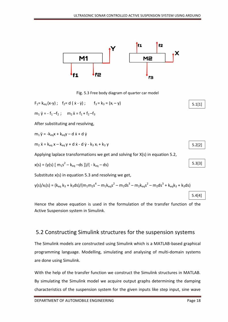
Fig. 5.3 Free body diagram of quarter car model
F1= keq (x-y) ; f2= d ( ẋ - ẏ) ; f3 = k3 = (xi – y)
m1 ӱ = - f1 –f2 ; m2 ẍ = f1 + f2 –f3
After substituting and resolving,
m1 ӱ = -keqx + keqy – d ẋ + d ẏ
m2 ẍ = keq x – keq y + d ẋ - d ẏ - k3 xi + k3 y
Applying laplace transformations we get and solving for X(s) in equation 5.2,
x(s) = (y(s) [ m1s2 – keq –ds ])/( - keq – ds)
Substitute x(s) in equation 5.3 and resolving we get,
y(s)/xi(s) = (keq k3 + k3ds)/(m1m2s4 – m1keqs2 – m1ds3 – m2keqs2 – m2ds3 + keqk3 + k3ds)
Hence the above equation is used in the formulation of the transfer function of the
Active Suspension system in Simulink.
5.2 Constructing Simulink structures for the suspension systems
The Simulink models are constructed using Simulink which is a MATLAB-based graphical
programming language. Modelling, simulating and analysing of multi-domain systems
are done using Simulink.
With the help of the transfer function we construct the Simulink structures in MATLAB.
By simulating the Simulink model we acquire output graphs determining the damping
characteristics of the suspension system for the given inputs like step input, sine wave
5.1[1]
5.2[2]
5.3[3]
5.4[4]

ULTRASONIC SONAR CONTROLLED ACTIVE SUSPENSION SYSTEM USING ARDUINO
DEPARTMENT OF AUTOMOBILE ENGINEERING Page 19
input. Passive and active suspension systems are constructed using the blocks available
in the Simulink library and the output graphs of both systems are compared determining
which suspension system has better damping characteristics.
5.2.1 Passive suspension system
Fig. 5.4 Simulink model of a passive suspension system
Scope1 gives us the acceleration graph and scope we acquire the displacement graph.
After running the Simulink we obtain the output graph as shown below.
Fig. 5.5 Displacement graph of passive suspension system with step input signal
Step signal input (Road Disturbance)
Output (Displacement)
(response(Displacement)
ULTRASONIC SONAR CONTROLLED ACTIVE SUSPENSION SYSTEM USING ARDUINO
DEPARTMENT OF AUTOMOBILE ENGINEERING Page 20
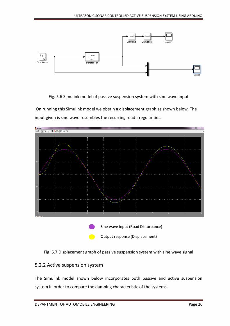
Fig. 5.6 Simulink model of passive suspension system with sine wave input
On running this Simulink model we obtain a displacement graph as shown below. The
input given is sine wave resembles the recurring road irregularities.
Fig. 5.7 Displacement graph of passive suspension system with sine wave signal
5.2.2 Active suspension system
The Simulink model shown below incorporates both passive and active suspension
system in order to compare the damping characteristic of the systems.
Sine wave input (Road Disturbance)
Output response (Displacement)
ULTRASONIC SONAR CONTROLLED ACTIVE SUSPENSION SYSTEM USING ARDUINO
DEPARTMENT OF AUTOMOBILE ENGINEERING Page 21
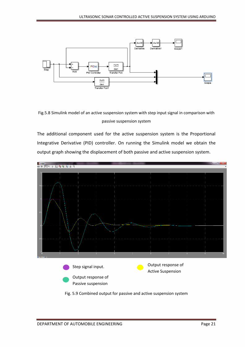
Fig.5.8 Simulink model of an active suspension system with step input signal in comparison with
passive suspension system
The additional component used for the active suspension system is the Proportional
Integrative Derivative (PID) controller. On running the Simulink model we obtain the
output graph showing the displacement of both passive and active suspension system.
Fig. 5.9 Combined output for passive and active suspension system
Step signal input.
Output response of
Passive suspension
Output response of
Active Suspension

ULTRASONIC SONAR CONTROLLED ACTIVE SUSPENSION SYSTEM USING ARDUINO
DEPARTMENT OF AUTOMOBILE ENGINEERING Page 22
The green line in the graph represents the displacement of passive suspension system
with step input signal and the yellow line indicates the displacement of active
suspension system. On comparing both the outputs of the system we can conclude that
on incorporating PID controller the displacement achieved is lesser than the step signal,
thereby showing a considerate amount of reduction in the vibration.
Fig. 5.10 Simulink model of active suspension system with sine wave input signal in comparison
with passive suspension system
Fig. 5.11 Displacement graph of active suspension system with sine wave input
Sine wave input.
Output response of
Passive suspension
Output response of
Active Suspension

ULTRASONIC SONAR CONTROLLED ACTIVE SUSPENSION SYSTEM USING ARDUINO
DEPARTMENT OF AUTOMOBILE ENGINEERING Page 23
5.3 Simscape
Simscape is a platform which is used to construct and simulate virtual systems before
constructing prototypes. Constructing an active suspension system actuated by DC servo
motor using Simscape.
The suspension system can be further divided into two parts:-
Construction of spring mass dashpot system
Construction of DC servo motor
Construction of spring mass dashpot system:-
A simscape model is created by typing a command ‘ssc_new’ in the Matlab command
window, which then directed to the simscape library.
Fig. 5.12 Creating a new model using simscape library
To create a model certain standard utilities are required as mentioned below:-
1. Solver configuration: This block identifies the solver parameters and the solver primarily
resolves the mathematical problem of the model prior to the simulation.

ULTRASONIC SONAR CONTROLLED ACTIVE SUSPENSION SYSTEM USING ARDUINO
DEPARTMENT OF AUTOMOBILE ENGINEERING Page 24
2. Simulink to PS (physical signal) convertor: This block is used to connect inputs of the
simulink sources to the physical system. Also converts the simulink input signal into
physical signal.
3. PS (physical signal) to Simulink convertor: This connects the outputs of the physical
system to the simulink scopes converting the physical input into a simulink output signal.
5.3.1 Spring mass dashpot system
Fig. 5.13 Physical representation of spring mass damper system
This spring mass system is given a step input with additional blocks which are the ideal
force source, the ideal translational motion sensor and mechanical translation reference.
This physical system represents passive suspension system as it consists of a simple
spring mass system.

ULTRASONIC SONAR CONTROLLED ACTIVE SUSPENSION SYSTEM USING ARDUINO
DEPARTMENT OF AUTOMOBILE ENGINEERING Page 25
1. Ideal force source: This block is used to generate a proportional force to the physical
signal input. As it represents to an ideal source for mechanical energy.
It has two inputs and one output, where S port is the physical signal port, R and C are
connected to the mechanical translation components. In this case R is connected to the
second mass and C is connected to the road input/ mechanical reference.
2. Ideal Translational Motion Sensor: The mechanical disturbances from the physical
system cannot be determined hence this block is used to convert the translational
motion into control signal as it easier to determine the displacement.
Here R port is connected to the sprung mass, C port is linked to the solver configuration
which is used to solve the mathematical problem. The P and V represent the position
and velocity respectively.
3. Mechanical Reference: This block represents a reference point however in this case it
represents the road surface.
After constructing the suspension system, we input values in the physical system
Vehicle Model
Parameters Symbol Numerical Value Unit
Sprung Mass Mass1 300 Kg

ULTRASONIC SONAR CONTROLLED ACTIVE SUSPENSION SYSTEM USING ARDUINO
DEPARTMENT OF AUTOMOBILE ENGINEERING Page 26
Unsprung Mass Mass 40 Kg
Suspension stiffness Spring1 4200 N/m
Tire Stiffness Spring3 8000 N/m
Damper co-efficient Damper 1000 Ns/m
Table No. 1 Input Parameters to the Simscape model of Spring mass Dashpot system.
Fig. 5.14 Inputs given to the spring mass dashpot system
Since this spring mass damper system represents the Passive suspension system, the
displacement of the suspension system with step input signal (resembles a bump on the
road) is shown below.
ULTRASONIC SONAR CONTROLLED ACTIVE SUSPENSION SYSTEM USING ARDUINO
DEPARTMENT OF AUTOMOBILE ENGINEERING Page 27
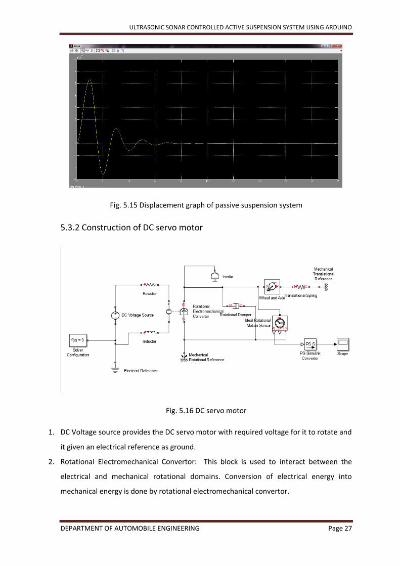
Fig. 5.15 Displacement graph of passive suspension system
5.3.2 Construction of DC servo motor
Fig. 5.16 DC servo motor
1. DC Voltage source provides the DC servo motor with required voltage for it to rotate and
it given an electrical reference as ground.
2. Rotational Electromechanical Convertor: This block is used to interact between the
electrical and mechanical rotational domains. Conversion of electrical energy into
mechanical energy is done by rotational electromechanical convertor.

ULTRASONIC SONAR CONTROLLED ACTIVE SUSPENSION SYSTEM USING ARDUINO
DEPARTMENT OF AUTOMOBILE ENGINEERING Page 28
The positive and negative terminals are connected to the resistor and inductor, whereas
R and C ports engage with the mechanical rotational ports.
3. The mechanical portion of the model is engaged with the R and C ports, where R port is
connected to the inertia which represents the inertia of the shaft and the C port is fixed
to the point in space i.e. mechanical rotational reference.
4. A viscous friction in the bearing of the motor is created by inserting the damper block
and the rotational motion is converting into translation motion by using the wheel and
axle block.
5. The motor is acted upon the spring where one end of the spring is connected to the
wheel and axle block and other end is linked to the mechanical reference.
6. To obtain the simulation on the simulink scope, a sensor block called the rotational
motion sensor to measure the motion of the shaft. The sensor block produces a physical
signal which can be converted into simulink in order to view it on the scope.
The sensor has four ports, where the R port is connected to mechanical rotational part,
C port is linked with the DC servo motor and A port is connected to the PS- simulink
block and scope which determines the movement of the motor in terms of a graph.
After running the DC servo motor model we view the simulink signal on the scope, the
movement of the shaft is determined in degrees by assigning degrees in the scope block.
The graph given below shows the shaft movement and settles at about 90 degrees.

ULTRASONIC SONAR CONTROLLED ACTIVE SUSPENSION SYSTEM USING ARDUINO
DEPARTMENT OF AUTOMOBILE ENGINEERING Page 29
Fig. 5.17 Movement of the DC motor shaft
5.3.3 Combining the spring mass dashpot system (passive suspension
system) and DC servo motor
A combination of these two physical systems we are able to achieve active suspension
system by slightly modifying the system.
An Ideal force sensor is used as a representation of an ultrasonic sensor which senses
the road irregularities and sends a signal to the DC servo motor changing the angle of
the shaft which in turn connected to the spring present between the sprung mass and
unsprung mass.
The R port is connected to the mechanical reference representing road surface and C
port is connected to wheel and axle block i.e. shaft movement. F port is the physical
signal to measure the force which is not required.
ULTRASONIC SONAR CONTROLLED ACTIVE SUSPENSION SYSTEM USING ARDUINO
DEPARTMENT OF AUTOMOBILE ENGINEERING Page 30
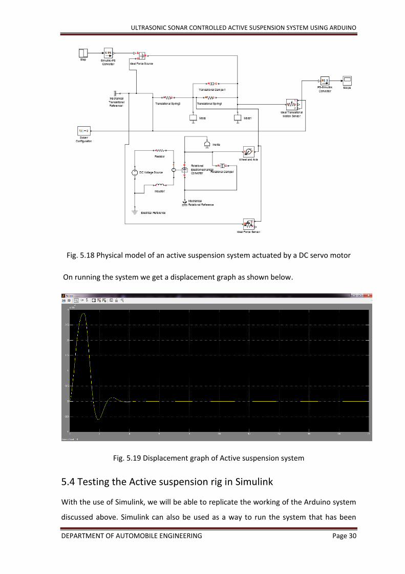
Fig. 5.18 Physical model of an active suspension system actuated by a DC servo motor
On running the system we get a displacement graph as shown below.
Fig. 5.19 Displacement graph of Active suspension system
5.4 Testing the Active suspension rig in Simulink
With the use of Simulink, we will be able to replicate the working of the Arduino system
discussed above. Simulink can also be used as a way to run the system that has been

ULTRASONIC SONAR CONTROLLED ACTIVE SUSPENSION SYSTEM USING ARDUINO
DEPARTMENT OF AUTOMOBILE ENGINEERING Page 31
built on the Arduino without using the Arduino IDE. Simulink offers more control and the
analysis of the performance of the system can be realised with the numbers and
graphical representations.
Simulink Add-ons being offered in the ‘Add-On Explorer’ of the MATLAB software
provides the support package needed for the MATLAB software to recognize the
Arduino hardware and the sensors being connected to it.
Fig. 5.20 Arduino Hardware support package page in MATLAB
This support package comes with the firmware software to use the third-party hardware
which here is the Arduino. The software includes updates to the Simulink Blocks that can
control the Arduino.
Fig. 5.21 Support package library.

ULTRASONIC SONAR CONTROLLED ACTIVE SUSPENSION SYSTEM USING ARDUINO
DEPARTMENT OF AUTOMOBILE ENGINEERING Page 32
The updated Simulink library browser looks as above. The Arduino blocks offer various
types of control signals, performance and outputting methods. Now initiating the
Simulink model construction, the connection of all the components is the same, with the
same pin numbers. WE open Simulink and start with adding the ultrasonic sensor block,
which can be found under the sensor drop down list under the Simulink Support Package
for Arduino Hardware.
Fig. 5.22 Ultrasonic sensor block.
1. Drag the above shown Simulink block into a new .slx file in Simulink.
Fig. 5.23 Dialgue box for pin connections.

ULTRASONIC SONAR CONTROLLED ACTIVE SUSPENSION SYSTEM USING ARDUINO
DEPARTMENT OF AUTOMOBILE ENGINEERING Page 33
The corresponding pin connections has to be entered in this dialgue box. And set the
sample time of the sensor to 0.1μs.
2. Add a Display block and connect it to the Ultrasonic sensor block, so that the
distance meaured in by the sensor iss diplayed in real-time. This display shows the
measurement to the nearest disturbance it detects in metric scale(meters).
Now as an instrction to the Arduino on what its input will be, we add an Arduino
Standard Read block. By connecting it to the Ultrasonic sensor, this block takes the input
signal and based on the incoming data, it sets the shaft postion of the standard Servo
motor. Double-clicking on the servo block, we can set the pin number to which the servo
motor is connected to on the Arduino board.
Fig. 5.24 Block parameters dialgue box
3. Since the data type that is sent out of the ultrasonic sensor, there will be a
requirement for us to convert it into a real-world value. To achieve this, we add a
convert block from under the Signal Attribute section in the Simulink library.
Fig. 5.25 Data type conversion dialgue box

ULTRASONIC SONAR CONTROLLED ACTIVE SUSPENSION SYSTEM USING ARDUINO
DEPARTMENT OF AUTOMOBILE ENGINEERING Page 34
Converting the output into a Real World Value and scaling of the output using data type
conversion block.
4. The signals with which the components are communicating are of very low energy
level, since the software has to work with external components and their supply is
of digital type. Therefore a gain block of gain value of about 100 is added to the
signal going to the servo motor. A gain value of 100 is given to the block.
Fig. 5.26 Block paramters: Gain
5. Finally to relaise the perfomance in graphical representation, we add a scope to
view the performance numbers and peak signal values. In the scope to merge the
signal, the bus creator block is added right before it. A signal from the Ultrasonic
sensor, and one from the Servo motor is given as two signal inputs to the bus
creator, which creates a bus with the combination of the two and send it to the
Scope.
Fig. 5.27 Complete Simulink model

ULTRASONIC SONAR CONTROLLED ACTIVE SUSPENSION SYSTEM USING ARDUINO
DEPARTMENT OF AUTOMOBILE ENGINEERING Page 35
The final completed Simulink diagram is as shown above. Before preparing the block
diagram and generating the code to run on the Arduino, necessary steps have to be
taken to set the actions that are to take place on the external hardware. On navigating
to the tools tab in the Simulink window, we set the program to run on the target
hardware. We arrive at the Configuration Parameter window of the .slx model we just
have completed. This message is displayed on the MATLAB command window upon
successful connections establishment.
Fig. 5.28 MATLAB Command window
Before proceeding to configure the hardware, the harware needs to establish
connection. The PC connection cable is used to connect the Arduino board via a USB
cable. Only open successful recognition and proper installation of all the device drivers,
the Arduino board is detected by the PC or the workstation that is being used. It is also
necessary to check for the COM port being used by ht eowkrstation to communicate
with the board. This information will be usefull while configuring the hardware in
Simulink.
Fig. 5.29 Configuration settings.

ULTRASONIC SONAR CONTROLLED ACTIVE SUSPENSION SYSTEM USING ARDUINO
DEPARTMENT OF AUTOMOBILE ENGINEERING Page 36
Under Hardware Implemtation, necessary details have to be filled. Like the type of
hardware board used, the COM port number.
Once this has been completed, it is time to complie the model, generate the code for the
model and upload onto the Arduino board via the USB cable. The code generation
process for the model is taken care of the Simulink software. With the completion of the
debugging by the software, it begins to build the virtual model and prepares to send it to
the Arduino board.
Fig: 5.30 The software preparing to send the model to the Arduino.
Once the program with the instructions have been uploaded to the Arduino board, it
begins to perform its functions. We will now be able to view the performance of the
virtual Active suspension rig with the help of the Scope.
Ultasonic signal.
Servo Shaft movement.
Fig. 5.31 Output response graph.
The display from the scope is as seen above. The red line in the scope denotes the
signals picked up by the Ultrasonic sensor, which is the distance to the distrubance it

ULTRASONIC SONAR CONTROLLED ACTIVE SUSPENSION SYSTEM USING ARDUINO
DEPARTMENT OF AUTOMOBILE ENGINEERING Page 37
T R
Distance to pothole from
the road level
senses. For example, the distance sensed by the sensor remains constant when the
vehcile is in it’s idle/ resting condition which is the level or the height at which the
vehicle floor sits from the ground. Keeping the sensor aimed at the ground, it is
constantly sensing the change or disturbance to the road’s surface.
Case1:- Detecting a pothole.
If the vehicle is in motion and is approaching a pothole of certain depth, the sensor
keeps sending data to the Arduino after deteting the change in the distance as the
vehicle approaches the pothole. In this case as a pothole would mean a dip, that is an
increase in the distance to the ground. By setting the sample time to 0.1μs allows more
tracing of the road surface to be possible, irrespective of the speed the vehilce is moving
at.
Fig. 5.32 Vehicle approaching pothole.
An approximate response graph to the case discussed above would be as shown.The
stable part at the start of the graph would be the position in which the vehicle is stable.
The dip in the graph is equal to the depth of the pothole. If we look closely it is also seen
that the system is able to trace the change in the shape of the pothole too. This can be
obtained to even more accuracy by increasing the sample time of the sonar sensor, to
adjust We can see in the graph that the same amount of movement is performed by the
servo shaft to cancel out the disturbance that has been picked up and the vehicle would
return to its stable/normal position.

ULTRASONIC SONAR CONTROLLED ACTIVE SUSPENSION SYSTEM USING ARDUINO
DEPARTMENT OF AUTOMOBILE ENGINEERING Page 38
Fig. 5.33 Output reaction prouduced in the graph.
Case 2:- Detecting a Bump or Road unevenness.
Fig. 5.34 Vehicle approaching bump on road.
In a similar way, uneven roads, bumps, protrusions on the surface of the road are sensed
too. Here too the tracing of the irregularity is possible and the servo shaft connected to
the suspension of the vehicle is moved to comepensate to suppress the disturbance and
keep the ride stable. Once the vehcile is over or has passed the irregularity on the road,
the vehcile returns to its normal height/poistion.
T R
Distance bump from road level
Depth of Pothole

ULTRASONIC SONAR CONTROLLED ACTIVE SUSPENSION SYSTEM USING ARDUINO
DEPARTMENT OF AUTOMOBILE ENGINEERING Page 39
This performance of the system during this case is seen in the graph as shown below.
Fig. 5.35 Second case output reaction seen in the graph.
The reaction to such a scenario as discussed above would be as shown. The graph begins
by showing that the vehcile is in its rest position, and encounters round humps or
distrubances ahead of it. The sensor senses and sends the data of the height of the
disturbance to the Arduino board. Whivh inturn instructs the servo motor to adjust it’s
shaft position as the vehcile approaches it and the vehicle successfully overcomes the
disturbance in real time.
This system can be subjected to further testing and analysis to improve the real life
capability of the proposed Active Suspension System. This can be done by incorporating
this suspension system on a prototype model.
5.5 Electronic components
The Electronics play an important role in any of the modern equipment. Electronic is a
vast field which has a variety of components like sensors, processors, microprocessors
and so on. To achieve our goal we have used a basic class of components.
Height of the

ULTRASONIC SONAR CONTROLLED ACTIVE SUSPENSION SYSTEM USING ARDUINO
DEPARTMENT OF AUTOMOBILE ENGINEERING Page 40
The components used are: -
HC-SR04 ultrasonic Sensor
Fig. 5.36 Ultrasonic sensor module[1].
This sensor uses sonar in determining the distances, similar to what animals like bats
and dolphins do. It is excellent in offering non-contact range detection with high
accuracy and stable readings. It has a range from 2cm to 400 cm or 1feet to 13 feet. The
operation of the sonar does not depend on light; therefore, it is unaffected by the
amount of light available during its use, which serves as huge advantage in using it in the
model.
This component as seen in the figure has a transmitter and a receiver built in it. To start
the measurement, the TRIGGER pin of the sensor must receive a pulse high which is of
5V for at least 10μs. This will initiate the sensor and will transmit out 8 cycle of
ultrasonic burst at 40 kHz and wait for the signals to be reflected when an obstacle
comes in the way of the transmitted ultrasonic burst. When the sensor detects the
signals from the receiver, it will set the Echo pin to high and delay for a period which is
in proportion to the actual distance the signal burst has travelled. To obtain the distance
it measures the width of the Echo pin.
Time= Width in cms= Time/48
The sonar’s generation of the trigger signal can be based on the program that runs in the
software used, and hence sends the space measurement to the user when done.

ULTRASONIC SONAR CONTROLLED ACTIVE SUSPENSION SYSTEM USING ARDUINO
DEPARTMENT OF AUTOMOBILE ENGINEERING Page 41
Arduino Uno Board
An Arduino is a microcontroller which can be easily programmed at any instant of time.
Since its inception it is being used in the field of robotics and by professionals, hobbyists
and students to build and create devices. The Arduino interacts with the environment
using the sensors or actuators that are connected as peripherals. It is basically an open
source minicomputer that is used to program and control electronic devices by taking
inputs and controlling the outputs from the electronic devices.
Fig. 5.37 Arduino Uno Board[2].
Arduino uses a hardware known as Arduino IDE (Integrated Development Environment),
they can be programmed using C or C++ in the Arduino IDE language. This board
connects through the USB cable and programs can be burned into the board by
uploading it.
Among the various types of Arduino boards in the market, Arduino Uno is the most
standard board available, with its biggest advantage being that the USB port serves as a
dual purpose of supplying power and interfacing with the board. T
he board also provides for an external supply port which can be powered by a 9-12V DC
adapter once the program has been uploaded to the board. On board it features 14
Digital I/O pins and 6 Analog I/O pins to be used to exchange and interface data between
the board and the electronic devices.
ULTRASONIC SONAR CONTROLLED ACTIVE SUSPENSION SYSTEM USING ARDUINO
DEPARTMENT OF AUTOMOBILE ENGINEERING Page 42
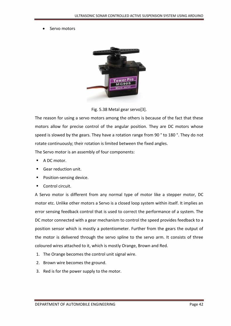
Servo motors
Fig. 5.38 Metal gear servo[3].
The reason for using a servo motors among the others is because of the fact that these
motors allow for precise control of the angular position. They are DC motors whose
speed is slowed by the gears. They have a rotation range from 90 ° to 180 °. They do not
rotate continuously; their rotation is limited between the fixed angles.
The Servo motor is an assembly of four components:
A DC motor.
Gear reduction unit.
Position-sensing device.
Control circuit.
A Servo motor is different from any normal type of motor like a stepper motor, DC
motor etc. Unlike other motors a Servo is a closed loop system within itself. It implies an
error sensing feedback control that is used to correct the performance of a system. The
DC motor connected with a gear mechanism to control the speed provides feedback to a
position sensor which is mostly a potentiometer. Further from the gears the output of
the motor is delivered through the servo spline to the servo arm. It consists of three
coloured wires attached to it, which is mostly Orange, Brown and Red.
1. The Orange becomes the control unit signal wire.
2. Brown wire becomes the ground.
3. Red is for the power supply to the motor.
ULTRASONIC SONAR CONTROLLED ACTIVE SUSPENSION SYSTEM USING ARDUINO
DEPARTMENT OF AUTOMOBILE ENGINEERING Page 43
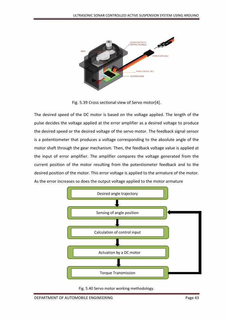
Fig. 5.39 Cross sectional view of Servo motor[4].
The desired speed of the DC motor is based on the voltage applied. The length of the
pulse decides the voltage applied at the error amplifier as a desired voltage to produce
the desired speed or the desired voltage of the servo motor. The feedback signal sensor
is a potentiometer that produces a voltage corresponding to the absolute angle of the
motor shaft through the gear mechanism. Then, the feedback voltage value is applied at
the input of error amplifier. The amplifier compares the voltage generated from the
current position of the motor resulting from the potentiometer feedback and to the
desired position of the motor. This error voltage is applied to the armature of the motor.
As the error increases so does the output voltage applied to the motor armature
Fig. 5.40 Servo motor working methodology.
Sensing of angle position
Calculation of control input
Actuation by a DC motor
Torque Transmission
Desired angle trajectory

ULTRASONIC SONAR CONTROLLED ACTIVE SUSPENSION SYSTEM USING ARDUINO
DEPARTMENT OF AUTOMOBILE ENGINEERING Page 44
5.6 Setting up the sensor and actuator to the Arduino.
The connection of the sensors and components was made as follows:-
The power to the Arduino board is given either by using a 5V supply or by the USB connection to the computer.
Connect the Servo’s power wire (red pin) to the 5V pin seen on the Arduino board.
Connect the Signal wire (orange wire) to the digital pin 4 on the Arduino.
Connect the Ground wire (brown wire) to the ground pin.
Connect the VCC or the power supply to the positive rail on the breadboard.
Connect the TriggerPin to pin 3.
Connect the EchoPin to pin 2.
Fig. 5.41 Connected view of the components.
5.6.1 Configuration of the program for the Arduino board.
Proceeding with the construction of the suspension model, the development of the
program that has to be uploaded or burnt to the Arduino board has to be created. This

ULTRASONIC SONAR CONTROLLED ACTIVE SUSPENSION SYSTEM USING ARDUINO
DEPARTMENT OF AUTOMOBILE ENGINEERING Page 45
can be done by writing the code on Arduino IDE and uploading it to the Arduino using
the software package.
Fig. 5.42 Arduino IDE sketch page.
The figure above is a preview of an Arduino IDE sketch. Since Arduino is an open sourced
product, there are various manufacturers building Arduino boards. The IDE is a software
developed so that users are allowed to communicate with the board for the use of its
required features.
The steps in configuring an Arduino board is to first write the required code in an IDE
sketch, giving instructions to the board as to what is to be performed. Since in the case
of the project, there are components involved, we need to declare them and assign the
pins to which they are connected to in the board. Like in all of the programming
languages and since the Arduino uses codes written using C or C++, they too have the
ability to use libraries. These libraries can be used in a sketch by simply importing it or
including a #include statement. As servo motor is being where the output action is to be
performed, we include the servo library in the Arduino sketch.
One other pre-requisite that is being used in this sketch for this project is the ‘New Ping
library’. The use of New Ping library is to bring the features of an HC-SR04 sensors
features into effect. This library works with any type of ultrasonic sensor models
like: SR04, SRF05, SRF06, DYP-ME007. Therefore, the option of an upgrade to the sensor
is a viable choice.

ULTRASONIC SONAR CONTROLLED ACTIVE SUSPENSION SYSTEM USING ARDUINO
DEPARTMENT OF AUTOMOBILE ENGINEERING Page 46
5.6.2 The Code
Fig. 5.43 Code written in Arduino IDE
The sketch for the Arduino is as seen above. Here the first part of the code is to include
the libraries, which is the function of the first two lines #include statements. The next
part of the code is determining where the sonar sensors pins are attached to, that is the
ServoPin, EchoPin and the TriggerPin.
Now we refer to the connections we have made and list the number against each pin in
the sketch.
ServoPin=11;
TriggerPin=3;
EchoPin=2;
‘NewPing sonar(TiggerPin , EchoPin, 100)’, this piece of the sketch is where we can limit
the maximum distance the sonar is allowed to sense. In this case ‘100’ limits it to a
hundred centimetres.

ULTRASONIC SONAR CONTROLLED ACTIVE SUSPENSION SYSTEM USING ARDUINO
DEPARTMENT OF AUTOMOBILE ENGINEERING Page 47
Next is to call for the servo library to set its values and functions. ‘Serial.begin(9600)’,
instructs the Arduino to exchange messages with the serial monitor at the rate of speed
of 9600 bits per second(baud rate).
Moving on to the part of the code that is to be run repeatedly, we use a
Moving on to the part of the code that is to be run repeatedly, we the NewPing library
feature where it sends out a ping and looks for the response. We declare it here in the
sketch in centimetres.
Int cm= sonar.ping_cm
By declaring an angle that is based on the distance that is sensed by the ultrasonic
sensor, so that the servo is told to move according to the angle which in turn is the
distance output by the sensor. This is done by using a mapping function, where the
servo is told to take the distance values from the ultrasonic sensor and move the servo
shaft with the same speed and change in the distance accordingly. The map function
basically maps the distance values as the input to the servo shaft position/angles in real
time. By taking the maximum and minimum values of the distance that the sonar can
sense which acts as the input to which the servo has to react to, and also taking the
rotation angles to be used for the servo shaft’s rotation.
Int angle = map(cm, 0, 35, 90, 180);
Here 0 and 35cms become the range within which the sonar detects disturbance or
change, and 90- 180 degrees is the servo shaft’s range of rotation.
servo.write(angle); becomes the code for letting the servo realise its input.
delay(60); is the part where a delay of 60μs is applied.
Once the code is complete the sketch is compiled and uploaded to the Arduino board.
Fig. 5.44 Status of code compilation and upload message shown in the Ardunio IDE

ULTRASONIC SONAR CONTROLLED ACTIVE SUSPENSION SYSTEM USING ARDUINO
DEPARTMENT OF AUTOMOBILE ENGINEERING Page 48
Fig. 5.45 Output of distance recorded seen on the Serial Monitor.
Upon successful compilation and uploading the sketch to the Arduino board the Servo
motor begins to move accroding to the disturbsnce infront of the sonar sensor.
Fig. 5.46 Ultrasonic sensor signal projection.
Fig. Servo motor rotation[5].
Disturbance sensed by the sonar is
given as the input to servo’s shaft.
ULTRASONIC SONAR CONTROLLED ACTIVE SUSPENSION SYSTEM USING ARDUINO
DEPARTMENT OF AUTOMOBILE ENGINEERING Page 49
Servo receives the input distance and with the use of the map function, the distance is
seen as the servo shafts rotation.
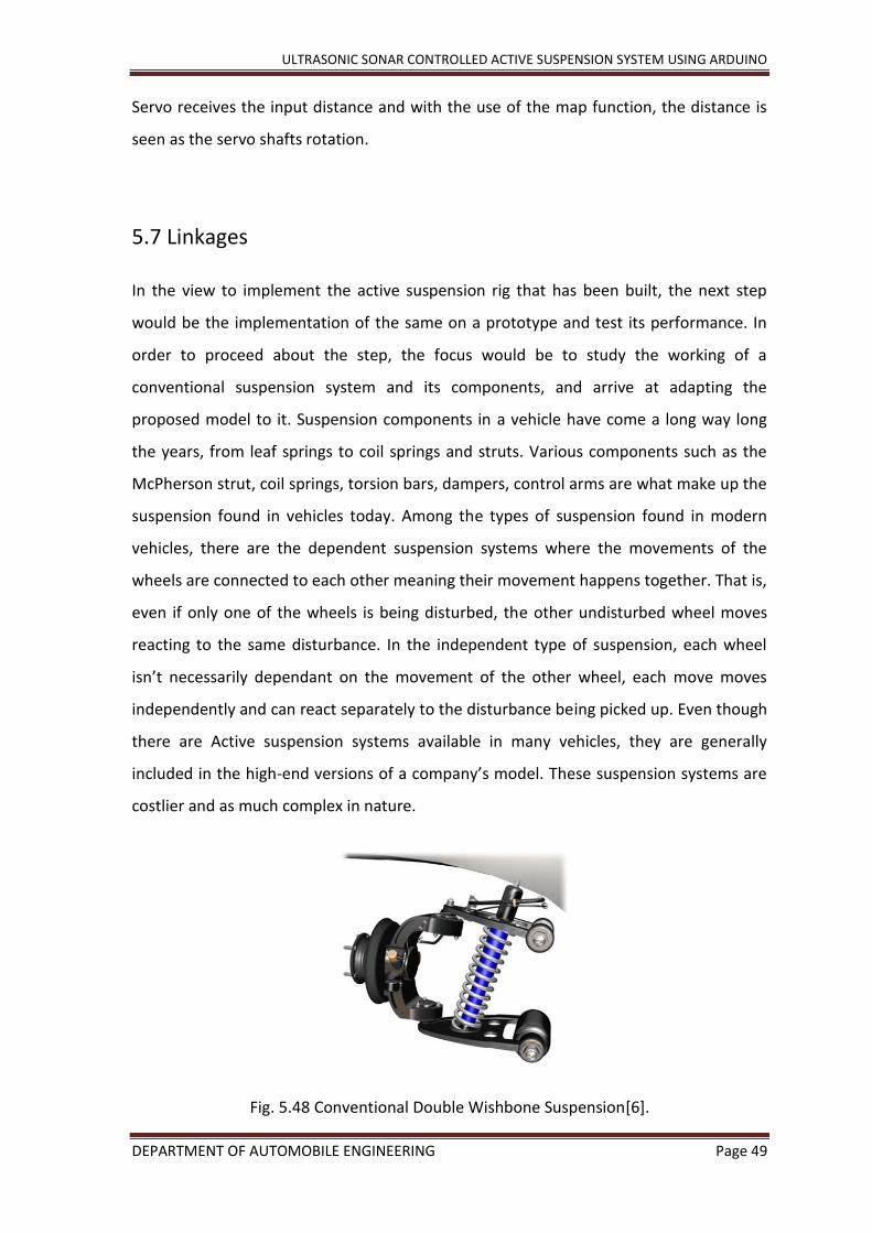
5.7 Linkages
In the view to implement the active suspension rig that has been built, the next step
would be the implementation of the same on a prototype and test its performance. In
order to proceed about the step, the focus would be to study the working of a
conventional suspension system and its components, and arrive at adapting the
proposed model to it. Suspension components in a vehicle have come a long way long
the years, from leaf springs to coil springs and struts. Various components such as the
McPherson strut, coil springs, torsion bars, dampers, control arms are what make up the
suspension found in vehicles today. Among the types of suspension found in modern
vehicles, there are the dependent suspension systems where the movements of the
wheels are connected to each other meaning their movement happens together. That is,
even if only one of the wheels is being disturbed, the other undisturbed wheel moves
reacting to the same disturbance. In the independent type of suspension, each wheel
isn’t necessarily dependant on the movement of the other wheel, each move moves
independently and can react separately to the disturbance being picked up. Even though
there are Active suspension systems available in many vehicles, they are generally
included in the high-end versions of a company’s model. These suspension systems are
costlier and as much complex in nature.
Fig. 5.48 Conventional Double Wishbone Suspension[6].

ULTRASONIC SONAR CONTROLLED ACTIVE SUSPENSION SYSTEM USING ARDUINO
DEPARTMENT OF AUTOMOBILE ENGINEERING Page 50
Up & down movement to
dampen the disturbance
travel
Keeping these factors in mind, the best way to adapt the Active suspension rig would be
to keep in check the cost incurred in the adaptation, involving minor changes to a
conventional suspension but achieve the goal of making it smarter and efficient.
A theoretical application of possible change to the suspension system would be to
achieve control over the moving part that sets the chassis separated from the
disturbance passed on above from the wheels. This is achieved by keeping the control,
i.e. the servo motor that outputs the shaft movement according to the disturbance
being picked up, between the control arms connection to the chassis frame.
Fig. 5.49 Detailed view of Double-Wishbone Suspension[7].
From the figure above showing the moving components in a double wishbone/control
arm system, studying its movement and also adhering to the factors discussed above the
theoretical model adaptation for this project has been proposed as shown below. The
idea of involving a second shock is owed to the present Active suspension setups
available. Studying their means of achieving control over the vehicles suspension
allowed us to understand its working and has resulted in the incorporation of a similar
theoretical design. The figure shown above is in reference to small scale model of a
vehicle that has been considered for this project. Theoretical sketch for such a system is
as shown below
Connection to chassis
frame
Single shock absorber
Probable point of
control
ULTRASONIC SONAR CONTROLLED ACTIVE SUSPENSION SYSTEM USING ARDUINO
DEPARTMENT OF AUTOMOBILE ENGINEERING Page 51
Fig. 5.50 Theoretical sketch for designed system.
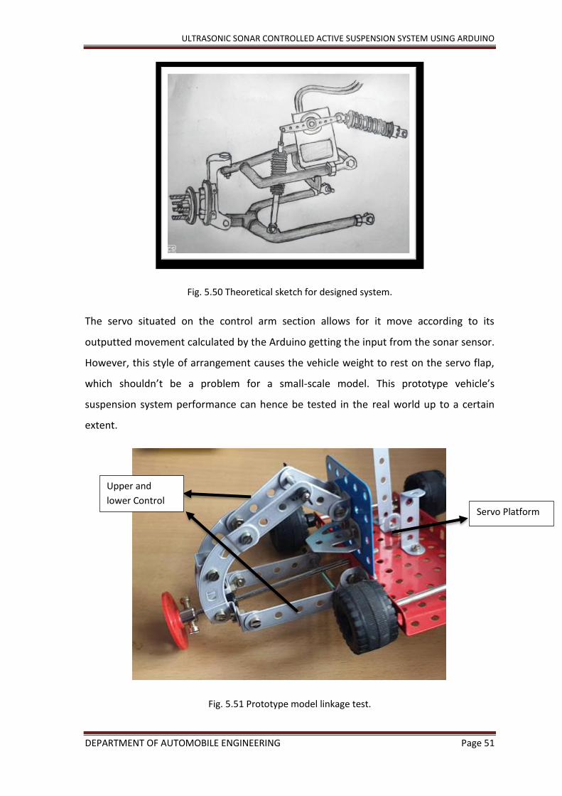
The servo situated on the control arm section allows for it move according to its
outputted movement calculated by the Arduino getting the input from the sonar sensor.
However, this style of arrangement causes the vehicle weight to rest on the servo flap,
which shouldn’t be a problem for a small-scale model. This prototype vehicle’s
suspension system performance can hence be tested in the real world up to a certain
extent.
Fig. 5.51 Prototype model linkage test.
Servo Platform
Upper and
lower Control
arm linkage

ULTRASONIC SONAR CONTROLLED ACTIVE SUSPENSION SYSTEM USING ARDUINO
DEPARTMENT OF AUTOMOBILE ENGINEERING Page 52
Moving on to the implementation in a bigger actual scale, the system remains the same
but the actuator or the control has to be varied. A pneumatic cylinder can be used as a
viable replacement for the servo motor in a larger scaled model application. However, in
order to provide solid validity of this proposal theoretically, there need to be
considerations of the vehicles centre of gravity based on the engine positions. A front
mounted engine vehicle will have majority of its weight in the front, and in the rear for a
rear mounted vehicle and the best of both worlds in the case of a mid-engine vehicle.
Drawing inspiration from the suspension system introduced in the 2018 Ford GT. As seen
below the system uses a double wish bone system with a push rod in between the lower
and the upper control arm which makes for a similar arrangement as the proposal. Now
the Ford GT’s system uses an electronically controlled spool valve that is in turn
connected to the push rod resulting in the control arms movement.
Fig. 5.52 Cylinder retracted [8]
Fig. 5.53 Cylinder extended [9]
Multimatic eDSSV,
spool valve.
Pushrod lifting
the lower arm
Torsion bar

ULTRASONIC SONAR CONTROLLED ACTIVE SUSPENSION SYSTEM USING ARDUINO
DEPARTMENT OF AUTOMOBILE ENGINEERING Page 53
Chapter 6
Conclusion
Suspension system is the most important part of an automobile that determines the ride
quality, safety, road grip and provides the relative motion between the sprung and un-
sprung mass of the vehicle. It consists of components such as coil spring, dampers,
mechanical struts, etc. Over the years the automotive industries have adapted the
technological improvements to improvise and obtain a smarter and efficient suspension
system and thus, the suspension system is broadly classified as Passive, Semi-Active,
Active suspension system. However, these systems are extremely expensive and are
harder to maintain, hence an alternative design for an active suspension was designed
using ultrasonic sensor, an Arduino unit, and servo motor. The idea behind this
particular design was to create a cheaper model of suspension system that can
effectively perform all the functions as that of the conventional active suspension
system.
The designed was theoretically tested by creating mathematical models and feeding the
same to two different domains in the MATLAB tool. The design was tested under
Simulink and Simscape tools and both the results proved that the new design performed
the functions of active system as it had a convenient output graph when compared to
the passive system. To demonstrate the mechanical functioning of this system, a small
scaled linkage was constructed and attached to the activating unit.
Although a model of 1:1 ratio couldn’t be fabricated for the design, it was concluded
theoretically that the new design performed on par with the conventional active
suspension system and could be implemented as a cheaper alternative.

ULTRASONIC SONAR CONTROLLED ACTIVE SUSPENSION SYSTEM USING ARDUINO
DEPARTMENT OF AUTOMOBILE ENGINEERING Page 54
References
Papers
1. Nourdine Aliane, A Matlab/Simulink- Based Interactive Module for Servo System
Learning, IEEE transactions on education, Vol. 53, No. 2, May 2010.
2. Abhilash Ingale ,Modeling Mass-Spring-Damper System using Simscape, IJERA, Vol.
8, Issue 1, ( Part -III) Jan 2018, pp.30-33.
3. Florin Andronic, Simulating Passive Suspension On An Uneven Track Surface, Journal
Of Engineering Studies And Research – Volume 20 (2014) No. 1.
4. Sanjay Singh, Design Of Pi Controller To Minimize The Speed Error Of D.C. Servo
Motor, IJSTR Vol 1, ISSUE 10, Nov 2012.
Equations
[1],[2],[3],[4] - https://www.semanticscholar.org/paper/Research-and-Simulation-on-
New-Active-Suspension-Zhou/0fb027656dc61693665272c4491dfe6391bc742e
Figures
[1] – https://potentiallabs.com/cart/HC-SR04-Ultrasonic-Proximity-sensor
[2] – https://robu.in/product/arduino-uno-r3-ch340g-atmega328p-devlopment-board/?gclid-
=Cj0KCQjwlN32BRCCARIsADZ-J4sP_v-Z3EOoavxWwH6k1n_bWgFwkzNo-EclP6tr477Xyhh--
waXBk8aAkQtEALw_wcB
[3] – https://robu.in/product/towerpro-mg90s-mini-digital-servo-2-2kg-0-08sec-13g/?gclid=Cj-
0KCQjwlN32BRCCARIsADZJ4uXaIILE5VisfQbBYr3gan852UvE7W9hGorh0Czo7eOWvf
[4] – https://www.brainy-bits.com/control-multiple-servos-with-joystick/
[5] – http://kitronik.co.uk/blogs/resources/control-a-360-degree-servo-with-a-bbc-microbit
[6] – https://www.purposegames.com/game/double-wishbone-suspension-system
[7] – https://medium.com/@you_wheel/automobile-suspension-design-101-part-iii-double-
wishbone-suspension-1edbcbe29232
[8] – https://www.youtube.com/watch?v=L0rAU0or3rQ
[9] – https://www.youtube.com/watch?v=L0rAU0or3rQ
Simscape References
https://www.youtube.com/watch?v=ESE2vw92nbA&feature=youtu.be
https://www.youtube.com/watch?v=B1TD_huqeBY&feature=youtu.be