Sultan Sonar Manual Rev 1.0 - MERCON
16
Sultan Sonar Manual Rev 1.0 A Higher Level of Performance www.hawkmeasure.com For more information, please visit > Sultan Acoustic Wave Series Level, Flow, Positioning, Collision Protection Quickstart
-
Upload
khangminh22 -
Category
Documents
-
view
0 -
download
0
Transcript of Sultan Sonar Manual Rev 1.0 - MERCON

Sultan Sonar Manual Rev 1.0
A Higher Level of Performance
www.hawkmeasure.comFor more information, please visit >
SultanAcoustic Wave Series Level, Flow, Positioning, Collision Protection
Quickstart
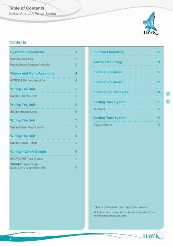
Table of Contents
2
Contents
System Components 3
Remote Amplifier 3
Panel Mount Remote Amplifier 3
Flange and Cone Assembly 4
AWR234 Remote Amplifier 4
Wiring The Unit 5
Sultan Remote Units 5
Wiring The Unit 6
Sultan Integral Units 6
Wiring The Unit 7
Sultan Panel Mount Units 7
Wiring The Unit 8
Sultan SMART Units 8
Wiring 4-20mA Output 9
SOURCING Type Output 9
SINKING Type Output (also 2 wire loop powered) 9
Incorrect Mounting 10
Correct Mounting 11
Installation Guide 12
Installation Guide 13
Installation Examples 14
Setting Your System 15
Quickset 15
Setting Your System 16
Relay Actions 16
This is a Quickstart for the Sultan series.
A full version manual can be downloaded from www.hawkmeasure.com
Sultan Acoustic Wave Series
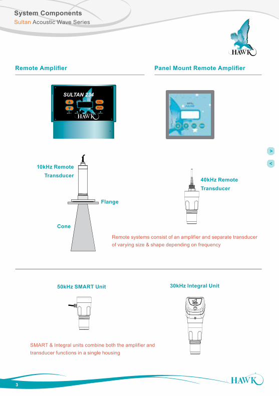
System ComponentsSultan Acoustic Wave Series
3
Remote Amplifier Panel Mount Remote Amplifier
CAL
RUN
RELAY 1 RELAY 2 RELAY 4 RELAY 5
SULTAN 234
RELAY 3
Remote systems consist of an amplifier and separate transducer of varying size & shape depending on frequency
10kHz Remote Transducer
Flange
Cone
40kHz Remote Transducer
50kHz SMART Unit 30kHz Integral Unit
SMART & Integral units combine both the amplifier and transducer functions in a single housing

Flange and Cone Assembly
4
AWR234 Remote Amplifier
Sultan Acoustic Wave Series
4
Tighten the locking ring down to the flange to fix the components in place.
2
Screw the flange assembly fully down onto the cone (as fardown as it will go until the partsare tightly fastened).
COMPLETE ASSEMBLY
1
Remove red cap (including cardboard).
3
Screw the transducer tightly down onto the flange and cone assembly.
Note! Direction of flange, smallest ring this way up ↑
(appearance above flange may differ for integral and smart units).
User mountings should only connect to the larger (lower) isolated mounting flange. No other part of the sensor assembly should touch any other structure or object.
5
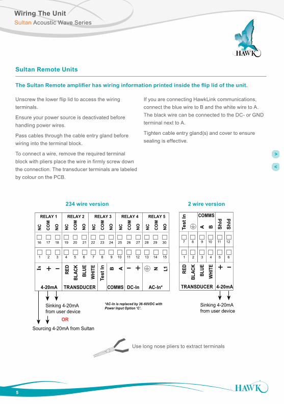
Sultan Remote Units
The Sultan Remote amplifier has wiring information printed inside the flip lid of the unit.
Unscrew the lower flip lid to access the wiring terminals.
Ensure your power source is deactivated before handling power wires.
Pass cables through the cable entry gland before wiring into the terminal block.
To connect a wire, remove the required terminal block with pliers place the wire in firmly screw down the connection. The transducer terminals are labeled by colour on the PCB.
If you are connecting HawkLink communications, connect the blue wire to B and the white wire to A. The black wire can be connected to the DC- or GND terminal next to A.
Tighten cable entry gland(s) and cover to ensure sealing is effective.
Wiring The UnitSultan Acoustic Wave Series
Sourcing 4-20mA from Sultan
Sinking 4-20mA from user device OR
+ – A 1L+– NB
RED
BLAC
KBL
UEW
HITE
Test
InIs
TRANSDUCER DC-In AC-In*4-20mA COMMS
RELAY 1
NC
CO
M
NO
RELAY 2
NC
CO
M
NO
RELAY 3
NC
CO
M
NO
RELAY 4
NC
CO
M
NO
RELAY 5
NC
CO
M
NO
1 2 3 4 5 6 7 8 9 10 11 12 13 14 15
16 17 18 19 20 21 22 23 24 25 26 27 28 29 30
B
RED
BLAC
KBL
UEW
HITE
Test
In
TRANSDUCER
COMMS
+ –
4-20mA
A Shld
Shld
Sinking 4-20mA from user device
1 2 3 4 5 6
7 8 9 10 11 12
*AC-In is replaced by 36-60VDC with Power Input Option ‘C’.
234 wire version 2 wire version
Use long nose pliers to extract terminals

6
Wiring The UnitSultan Acoustic Wave Series
Sultan Integral Units
The Sultan Integral unit has wiring information printed inside the flip lid of the unit.
Unscrew the lid to expose the facia.
The lid can be snapped back to allow easier access for wiring. When finished, first re-snap the double hinge into position before closing the lid. The top half of the facia is a flip cover which exposes the wiring terminals.
Ensure your power source is deactivated before handling power wires.
Pass cables through the cable entry gland before wiring into the terminal block.
To connect a wire, push down on the button above the terminal with a small flat head screwdriver and place the wire in the terminal. Release the pressure on the button to close the terminal and then pull on the wire to check that it is secure.
If you are connecting HawkLink communications, connect the blue wire to B and the white wire to A. The black wire should be connected to the Shld terminal.
Tighten cable entry gland(s) and cover to ensure sealing is effective.
RELAY 1
NC
CO
M
NO
RELAY 2
NC
CO
M
NO
COMMS
A B Shld
DC-In
+–
Test
In
4-20mA
Is1L N +–
AC-In
COMMS
A B Shld
+–
4-20mA
Test
In
Sourcing 4-20mA from Sultan
Sinking 4-20mA from user device OR
Sinking 4-20mA from user device
234 wire version 2 wire version
Ensure that any unused cable gland entries are plugged or sealed.
Wiring The UnitSultan Acoustic Wave Series
7
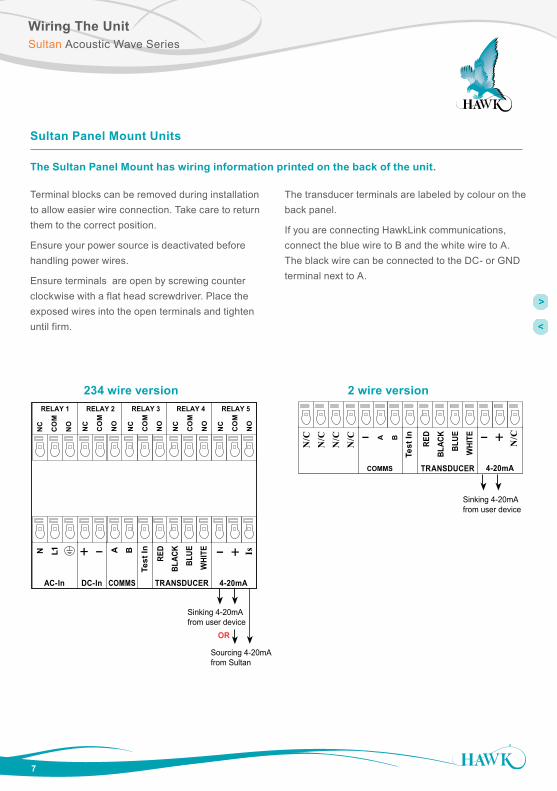
Sultan Panel Mount Units
The Sultan Panel Mount has wiring information printed on the back of the unit.
Terminal blocks can be removed during installation to allow easier wire connection. Take care to return them to the correct position.
Ensure your power source is deactivated before handling power wires.
Ensure terminals are open by screwing counter clockwise with a flat head screwdriver. Place the exposed wires into the open terminals and tighten until firm.
The transducer terminals are labeled by colour on the back panel.
If you are connecting HawkLink communications, connect the blue wire to B and the white wire to A. The black wire can be connected to the DC- or GND terminal next to A.
+–A1L + –N B
RED
BLAC
K
BLUE
WHI
TE
Test
In Is
TRANSDUCERDC-InAC-In 4-20mACOMMS
RELAY 1
NC
CO
M
NO
RELAY 2
NC
CO
M
NO
RELAY 3
NC
CO
M
NO
RELAY 4
NC
CO
M
NO
RELAY 5
NC
CO
M
NO
COMMS
A B +–
Test
In
4-20mA
N/C–
RED
BLAC
K
BLUE
WHI
TETRANSDUCER
N/C
N/C
N/C
N/C
Sourcing 4-20mA from Sultan
Sinking 4-20mA from user device OR
Sinking 4-20mA from user device
234 wire version 2 wire version

8
Wiring The UnitSultan Acoustic Wave Series
Sultan SMART Units
The Sultan SMART unit has wiring information printed inside the lid of the unit.
Screw Cap Version
Unscrew the lid to expose the terminals. It is recommended you remove the terminal block from the unit before wiring - to do this, insert a screw driver into one of the middle terminals to lever the block out.
Pass the cables through the cable entry gland before wiring in to the terminal block.
Ensure the terminal is open by screwing counter clockwise with a flat head screwdriver. Place the exposed wires into the open terminals and tighten until firm. Insert the block back into the unit when wiring is complete. Press firmly on the plug in terminal block to ensure it is fully home.
If you are connecting HawkLink communications, connect the blue wire to B and the white wire to A. The black wire can be connected to the DC- terminal next to B.
Tighten cable entry gland(s) and cover to ensure sealing is effective.
IP68 Sealed Cable Version
Connect the free ends of the cable following the wire colours as shown in the terminal diagrams.
AWSTD AWSTC
AWSTA
CO
M
NO
Test
in
A B
- + - +
BWN
OR
G
PPL
WT
BLU
BLK
RD
GR
N
YEL
RELAY COMMS DC-in 4-20mA
CO
M
NO
Test
in
A B
- + - +
BWN
OR
G
PPL
WT
BLU
BLK
RD
GR
N
YEL
RELAY COMMS DC-in 4-20mA
Outputs
- 4-20mA- Relay- Modbus Multidrop
Outputs
- Relay- Modbus Multidrop
Outputs
- 4-20mA(2) Modbus
RELAY RS - 485
24 Vdc
4-20mAcurrent sinking
RELAY RS - 485
24 Vdc
(1) (1)
Sinking 4-20mAfrom user device(loop powered)
Notes:
(1) - No internal connection(2) - Single Modbus connection PC to unit only Multidrop connection not recommended
For cable only models (without integrated junction box option), please use colors shown to denote wire functions.
For models with integrated junction box option, remove plug-in terminal blocks for easier wiring.
COMMS DC-IN
AB12-30VDC
+
RS 485
AC-IN
N L1
80-265VAC
RELAY 1
NC
CO
M
NO
RELAY 2
NC
CO
M
NO
COMMS
A B +–
Test
In
4-20mA
Is1L N +–
AC-In
Driving 4-20mA from Sultan to user PLC
Modulating 4-20mA from PLC input
–
Test
In
COMMS
A B –
Test
In +
COM
N / O
COMMS
A B –
Test
In +
COM
N / O
RELAY
Sinking 4-20mAfrom user device
+–
4-20mA
DC in
DC in
PURP
LE
WHI
TE
BLUE
BLAC
K
GRE
EN
YELL
OW
BRO
WN
ORA
NGE
PURP
LE
WHI
TE
BLUE
BLAC
K
RED
BRO
WN
ORA
NGE
PURP
LE
WHI
TE
BLUE
BLAC
K
RED
GRE
EN
YELL
OW
RELAY
AWSTA version AWSTC version
AWSTD version
9
Wiring 4-20mA OutputSultan Acoustic Wave Series
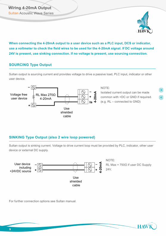
When connecting the 4-20mA output to a user device such as a PLC input, DCS or indicator, use a voltmeter to check the field wires to be used for the 4-20mA signal. If DC voltage around 24V is present, use sinking connection. If no voltage is present, use sourcing connection.
Sultan output is sourcing current and provides voltage to drive a passive load, PLC input, indicator or other user device.
SOURCING Type Output
+
–
NOTE:Isolated current output can be made common with +DC or GND if required.(e.g. RL – connected to GND)
+Is
–RL Max 270Ω
4-20mA
Use shielded
cable
Sultan output is sourcing current and provides voltage to drive a passive load, PLC input, indicator or other user device
4-20
mA
Voltage freeuser device
NOTE: Isolated current output can be made common with +DC or GND if required. (e.g. RL – connected to GND)
SINKING Type Output (also 2 wire loop powered)
Sultan output is sinking current. Voltage to drive current loop must be provided by PLC, indicator, other user device or external DC supply.
User device including
+24VDC source
NOTE: RL Max = 750Ωif user DC Supply 24V
Sultan output is sinking current. Voltage to drive current loop must be provided by PLC, indicator, other user device or external DC supply.
+
–
4-20
mA
Use shielded
cable
+
–NOTE: RL Max = 750Ω if user DC Supply 24V.
For further connection options see Sultan manual.

10
Incorrect MountingSultan Acoustic Wave Series
These are examples of common INCORRECT mountings which can prevent the unit from operating correctly.
Do NOT mount near infeed
POWDER
Mount away from infeed
DUAL OUTFEED
Use two transducer andselect sequence option to
avoid cross-talk.
Conical Shape Vessels Horizontal Cylindrical Tanks
Stockpiles, Stackers, Reclaimers
Do NOT mount cone or transducerface above roofline
Do NOT mount over or adjacent to any obstacles
Do NOT mount on angle in liquid applications

11
Correct MountingSultan Acoustic Wave Series
Mount away from infeed
Mount away from all obstacles
Mount perpendicularto liquids
Mount cone / transducerface within the vessel

Installation Guide
12
Sultan Acoustic Wave Series
Amplifier
Select a suitable mounting position that is protected from direct sunlight. If necessary, utilize a sun hood (Hawk supplies purpose made sun hoods). Observe the minimum and maximum temperature limits (-20°C/-4°F to 60°C/140°F) Do not mount near sources of electrical noise such as high current cables, motor starters, or variable speed drives. Avoid mounting in high vibration areas such as handrails and rotating plant. Use rubber absorption mounts if mounting in light vibration areas. Protect the PCB assembly before knocking out the cable and conduit entry holes.
Panel Mount
• Select a suitable position within a panel layout which allows clearance around the outside of the front panel of the unit and also behind the panel for clearance around the screw fixing clamps used to retain the unit.
• Ensure that sufficient space is available behind the panel to accommodate the depth of the amplifier housing, and also allow cable bend clearance for wiring to the terminals on the rear of the amplifier.
• Mark and cut a 90x90mm (3.54x3.54”) square cut out through the panel in the desired position.
• Insert the Sultan amplifier through the panel and install supplied screw clamps into the slotted holes in the amplifier housing.
• Tighten the screws until just firm to secure the amplifier in place.
• Connect wiring as required to the correct terminals on the removable rear panel connectors. When plugging connectors in to the rear panel, ensure that they are re-installed in the correct position.
Transducer
Selecting a suitable position to mount the transducer on the vessel is the single MOST IMPORTANT step. Please read all of the installation guide and contact your Hawk representative if you have any doubts or questions. The transducer face MUST be at least the blanking distance away from highest product level in the vessel.
Use common sense when selecting the transducer mounting position. A clear line of sight from the transducer to the product being monitored is required.
Take into account the change in material shape and level. The acoustic pulse must reflect back to the transducer.
Incorrect Mounting
Failure to mount the unit suitably can result in incorrect measurement and may cause process issues such as overfilling or damage to critical components.
Process Conditions
Ensure the process conditions within the vessel such as temperature, pressure and chemical composition of contents are within the specifications Sultan unit. The unit should not normally come into contact with the measured content.

13
Installation GuideSultan Acoustic Wave Series
Minimum Insertion
The transducer face or cone must be at least 50mm (2 inches) inside the tank.
If the transducer needs to be mounted above the roof line, use an appropriate standpipe or nozzle.
Moisture Seal
Sultan Integral and Smart units have cable glands with a moisture seal which must be tightened around the cable. Any unused glands must be plugged and sealed.
Transducer Location
It is vital that the Transducer has a clear view of the product surface at all times and is kept away from the inflow to avoid interference.
Blanking Distance
The unit will ignore any echoes and will never measure within its Blanking distance.
Minimum values must be respected. Where possible use the conservative values and increase this distance by 50% if there is foam, dust, steam, or condensation in the vessel being monitored. (Refer to Blanking Distance table.)
If using a flange mounting, use a rubber or neoprene gasket and washers. If using a nipple mounting, ensure that the mounting bracket is >6mm (0.24 in) from the rear of the transducer. Do not over tighten the lock nuts.
Nozzle mount
Minimum50mm (2")Blanking
Flush mount
Blanking
Stand pipe mount
Minimum50mm (2")Blanking
Blanking Distance Minimum Nominal Conservative
Transducer Frequency
AWRT50 50kHz 0.25m (10”) 0.3m (1ft) 0.35m (1.2ft)
AWRT40 40kHz 0.3m (1ft) 0.35m (1.2ft) 0.4m (1.3ft)
AWRT30 30kHz 0.35m (1.2ft) 0.4m (1.3ft) 0.5m (1.6ft)
AWRT20 20kHz 0.45m (1.5ft) 0.6m (2ft) 0.7m (2.2ft)
AWRT15 15kHz 0.6m (2ft) 0.7m( 2.2ft) 1.0m (3.2ft)
AWRT10 10kHz 0.75m (2.5ft) 1.1m (3.6ft) 1.3m (4.2ft)
AWRT5 5kHz 1.0m (3.2ft) 1.5m (4.9ft) 1.8m (5.9ft)Always use conservative nominated distances if possible.

14
Installation ExamplesSultan Acoustic Wave Series
SOLID (Granular)
FLUSH MOUNT
NOZZLEMOUNT
STAND PIPE MOUNT
Aim transducer atpoint of outfeed.
POWDER
Mount away from infeed
LIQUID
Transducer should vertical
DUAL OUTFEED
Two transducers may require anti-crosstalk
wiring setup (see manual)
Minimum50mm
MOUNTINGPOSITION
Vessel
InfedPipe
1/32/3
Minimum50mm
2" VERSION
min 20mminside tank Intrusive
pipe
Correct Incorrect
Vesselroof
Threaded mounting should only beused where a flange/cone mountingis impossible.Hawk recommends & suppliesfocaliser cones for all transducers.
Incorrect
Face must not be inside mounting

15
After the unit has been installed, mounted and powered you can now enter the Quickstart settings to get the unit operational in your application conditions.
Be sure to enter settings for High & Low level, App Type, Fill Rate and Empty Rate of your vessel.
If you are unsure of your specific fill & empty speed enter a value you are sure is faster than your process.
All of the mentioned settings (except Blanking) are in the ‘Quickset’ menu of the unit. You access this menu on the control pad by pressing CAL and entering Unlock code 0.
You may also need to set relay switch points. These are found in ‘Output Adjustment’. Relay alarms can be set on/off for hi/lo levels and failsafe.
Setting Your SystemSultan Acoustic Wave Series
(A)Blankingzone
(B)
(C)
(D)
(E)
Space
Material
LowLevel
HighLevel
Adjust vessel low level (maximum measured distance from transducer face)
Adjust vessel high Level (minimum measured distance from transducer face)
FeetMetresCentimetersInches
QuickSet
Unit
Low Level
High Level
Position SlurrySolidsLiquids
App Type
Empty Rate
Fill RateAdjustvesselfill rate
Adjustvesselempty rate
Fail Safe3.50mA3.80mA20.20mALast Known
Adjust Fail time (seconds)
Fail Time
CAL
Display Mode
CAL
CAL
CAL
CAL CAL
CAL CAL
CAL
CAL
CAL
Avg MatrlDiff O/PSpaceMaterial
CALMaterial%FlowVolumeFlow Tbl
Select unit of measurement from
Fill RateEmpty Rate
Select FailSafe mA output
Note: If using GosHawk PC comms you must change fill & empty rate AFTER selecting app type.
Filling damping.Number of pulsesaveraged for output
Fill Damp
Output Adj
Empty Damp
Rly Mode 1
Adjust Empty Damping
Set Relay Level 1 & Relay Level 2
DENENFSOFF
CAL
CAL
Rly Modes 2-5
CAL CALRlyL1
RlyL2CAL
Relay Triggers - Denergise, Energise, Fail Safe, Off
Example ENL1 = relay OFF pointL2 = relay ON pointExample DENL1 = relay ON pointL2 = relay OFF point
(A) Transducer Face - Top of Flange(B) End of Blanking Zone(C) High Level or 100% (20mA) position.(D) Product Level being measured(E) Low Level or 0% (4mA) position.
High Level = Distance A to CLow Level = Distance A to E
Parameter Description Options
Unit Adjust displayed measurement unit Inches Feet Meters Centimeters
Low Level Set Low level measurement point (4mA) Adjustable
High Level Set High level measurement point (20mA) Adjustable
Failsafe Set failsafe output & timer 20mA4mA
LastKnown20.20mA
3.80mA3.50mA
Failtime (seconds)
App Type Unit setup for specific application Various
FIll / Empty Speeds Unit setup for application process speed View Fast / Med / Slow Custom
(units per hour)
DispMode Set LCD measurement display mode Space Material Matrl%
Quickset

16
Setting Your SystemSultan Acoustic Wave Series
Relay Actions
• Set Relay Parameters in Output Adjustment menu
• The two relay levels are RlyL1 and RlyL2
• The display will show RlyL1 1, the last 1 indicated the Relay number (eg 1 to 5)
• L1 and L2 distances are measured from the transducer face
Sub-Menu Description Options
RlyL1 1-5Adjust Relay switch point (L1 must be < L2)
Adjustable
RlyL2 1-5Adjust Relay switch point (L2 must be > L1)
Adjustable
HI
OFF
TEST
LOW
EN
DEN
CAL
OFF
DELAYSENSITIVITY
EnergiseEN
DeEnergiseDEN
COMMS DC-IN
AC
GN
D to
met
al c
ase
12-30VDC
+7.
8.
RS 485
5.
B
6.
A
1 2 3 4 5 6 7 8 9 10
+ –4-20mA
AC-IN
A 1L+–
DC-IN4-20mA COMMSTRANSDUCER
NB
RELAY 1
NC COM
NO
RELAY 2
NC COM
NO
RELAY 3
NC COM
NO
RELAY 4
NC COM
NO
RELAY 5
NC COM
NO
Test
inIs
RED
BLAC
K
BLUE
WHI
TE
REMOTE AMPLIFIER
GLADIATOR TERMINAL
NC NOCOM NC NOCOM
NC NOCOM
POWER FAILURE
Stat
e 1
Stat
e 2
Relay ActionFailSafe FS
FailSafe FS
NC NOCOM
Relay Status
LED Status
Remote Amplifier terminal function labels
NC NOCOM
NC NOCOM
NC NOCOMNC NOCOM
NC NOCOMNC NOCOM
NC NOCOM NC NOCOM NC NOCOM NC NOCOM NC NOCOM
system operating normally
OFFpower/system/measurement failure
Below L2 or
RISING LEVEL
L1
L2
between L1 and L2 after passing below L2.
LOW LEVEL or
Above L1 or
FALLING LEVEL
L1
L2
between L1 and L2 after passing above L1.
HIGH LEVEL or
All company or product names are registered trademarks or trademarks of their respective owners.
Hawk Measurement Systems(Head Office)15 - 17 Maurice Court Nunawading VIC 3131, AUSTRALIA
Phone: +61 3 9873 4750Fax: +61 3 9873 [email protected]
Hawk Measurement 96 Glenn StreetLawrence, MA 01843, USA
Phone: +1 888 HAWKLEVEL (1-888-429-5538)Phone: +1 978 304 3000Fax: +1 978 304 [email protected]
DO
C-S
ULT
AN
-QU
ICK
v1.
11 1
016