Automatic Collision Avoidance System: Design, development and flight tests
21
30th Digital Avionics Systems Conference – Seattle WA, USA – Oct 16-20 2011 Automatic Collision Avoidance System: Design, Development and Flight tests Salvatore Luongo and Vittorio Di Vito Italian Aerospace Research Center (CIRA) Giancarmine Fasano, Domenico Accardo, Lidia Forlenza, and Antonio Moccia Department of Aerospace Engineering - DIAS, University of Naples “Federico II”
Transcript of Automatic Collision Avoidance System: Design, development and flight tests

30th Digital Avionics Systems Conference – Seattle WA, USA – Oct 16-20 2011
Automatic Collision Avoidance System: Design, Development and Flight tests
Salvatore Luongo and Vittorio Di Vito Italian Aerospace Research Center (CIRA)
Giancarmine Fasano, Domenico Accardo, Lidia Forlenza, and Antonio Moccia
Department of Aerospace Engineering - DIAS, University of Naples “Federico II”
30th Digital Avionics Systems Conference – Seattle WA, USA – Oct 16-20 2011
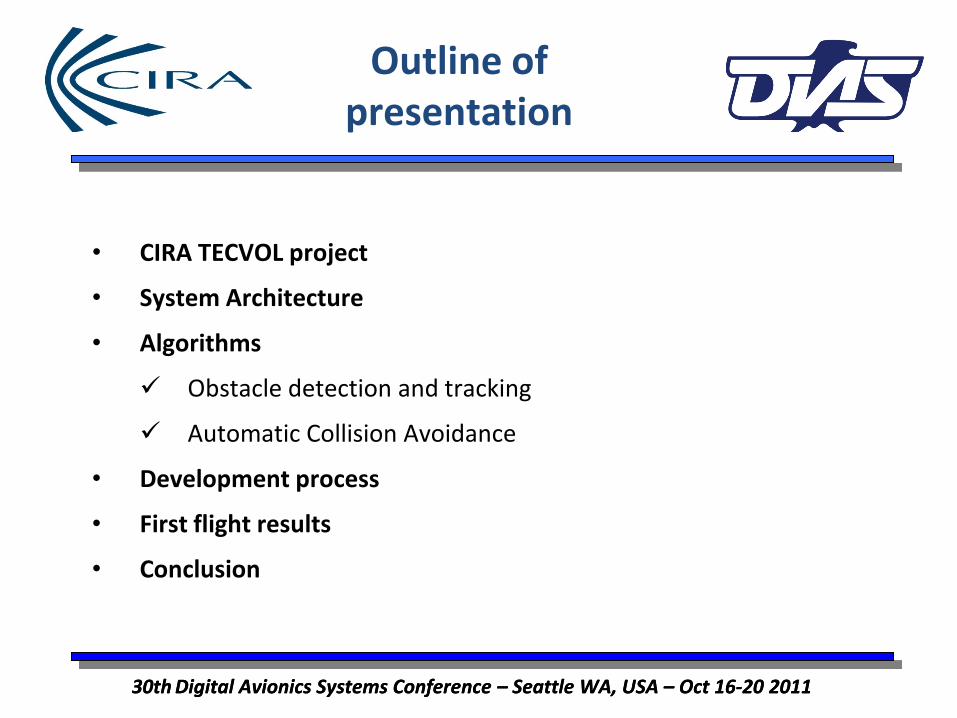
Outline of presentation
• CIRA TECVOL project
• System Architecture
• Algorithms
Obstacle detection and tracking
Automatic Collision Avoidance
• Development process
• First flight results
• Conclusion
30th Digital Avionics Systems Conference – Seattle WA, USA – Oct 16-20 2011

30th Digital Avionics Systems Conference – Seattle WA, USA – Oct 16-20 2011 30th Digital Avionics Systems Conference – Seattle WA, USA – Oct 16-20 2011
Collision Sense & Avoid: ELOS
• “Equivalent Levels of Safety”
must be guaranteed to allow UAVs to access NAS (FAA Order 7610.4K Ch. 12 Sec. 9-2 – August 5th 2004);
• Human pilot vision shall be replaced by a Sense&Avoid system with augmented capabilities: Obstacle Detection and Tracking; Conflict Detection; Autonomous Collision Avoidance.
Focus of this presentation. Sense-related aspects discussed in detail in presentation 5C.3

30th Digital Avionics Systems Conference – Seattle WA, USA – Oct 16-20 2011
CIRA TECVOL project
30th Digital Avionics Systems Conference – Seattle WA, USA – Oct 16-20 2011
• TECVOL project goal is the development of enabling technologies for autonomous UAS flight.
• Functions to be demonstrated in flight with optionally piloted VLA aircraft:
Autonomous Flight Path Execution Autonomous Landing Collision Sense&Avoid Enhanced Remote Piloting
• Department of Aerospace Engineering (DIAS) has been a partner of
CIRA in the design of the collision avoidance sensor system

30th Digital Avionics Systems Conference – Seattle WA, USA – Oct 16-20 2011
ACAS functional architecture
30th Digital Avionics Systems Conference – Seattle WA, USA – Oct 16-20 2011
The autonomous collision avoidance (ACA) module is based on two core algorithms: • a customized multi-sensor tracking software ensures that intruders’ dynamics is properly estimated • a decision making logic is able to handle collision conditions by commanding the autopilot to perform adequate evasive maneuvers whenever a potential conflict is detected.

30th Digital Avionics Systems Conference – Seattle WA, USA – Oct 16-20 2011
ACAS hardware architecture
30th Digital Avionics Systems Conference – Seattle WA, USA – Oct 16-20 2011

30th Digital Avionics Systems Conference – Seattle WA, USA – Oct 16-20 2011
Obstacle detection and tracking
• Multi-sensor tracking algorithm is based on an Extended Kalman Filter with linear dynamical model and non-linear measurement equation
• It can work in two operative modes:
• Stand-alone radar tracking
• Radar/EO tracking
• Estimates of position and velocity of eventual intruders are provided to the ACA system at 10 Hz
• Obstacle detection in EO images is carried out by means of a customized edge detection/labeling technique
• Further details provided in presentation 5C.3
30th Digital Avionics Systems Conference – Seattle WA, USA – Oct 16-20 2011

30th Digital Avionics Systems Conference – Seattle WA, USA – Oct 16-20 2011
• The Automatic Collision Avoidance algorithm on-line accomplishes two tasks:
• conflict detection
• conflict resolution
• In order to define the conflict situation, a proper volume (defined as “safety bubble”) is set around the intruder aircraft
• The ACA algorithm implements a spherical safety bubble whose dimensions are
where R is the radius of the sphere centered in the intruder aircraft, while R0 is the FAA minimum required safety distance.
30th Digital Avionics Systems Conference – Seattle WA, USA – Oct 16-20 2011
Automatic Collision Avoidance
mftRR 8.30410002 0 ≈==

30th Digital Avionics Systems Conference – Seattle WA, USA – Oct 16-20 2011
• The own aircraft is modeled (A/CA) as a point-of-mass object A
• The intruder, with its surrounding safety bubble, is modeled as a spherical object centered in the point B
• The relative velocity vector is considered:
• Distance at closest point of approach can be calculated as
• Collision condition is verified if and only if
Conflict detection
30th Digital Avionics Systems Conference – Seattle WA, USA – Oct 16-20 2011
NEDX
NEDY
NEDZA
B
AV
BV
rABV
NEDX
NEDY
NEDZA
B
AV
BV
rABV
R NEDX NEDX
NEDYNEDY
NEDZNEDZA
B
AV
AV
BV
BV
rABV
ABV
NEDX NEDX
NEDYNEDY
NEDZNEDZA
B
AV
AV
BV
BV
rABV
ABV
R
.2 rVV
Vrd AB
AB
ABAB
−
⋅=
.0<< randRdAB
BAAB VVV
−=

30th Digital Avionics Systems Conference – Seattle WA, USA – Oct 16-20 2011
Conflict resolution
• The strategy is based on the analytical solution of the following kinematic optimization problem:
to find the minimum change to be forced in speed vector of aircraft A (compatible with its envelope limitation and dynamic constraints) in order to avoid a collision with the spherical safety bubble surrounding aircraft B
• This leads to the formulation of a nonlinear constrained optimization problem:
30th Digital Avionics Systems Conference – Seattle WA, USA – Oct 16-20 2011
>∃∈∈
≥∀≥−
∆∫
0],[)(],,[)(
,)()(..
)(min
maxminmaxmin
0
,, 0
Aa
AAdAAA
dA
Bd
A
t
t AV
ttVVtV
ttRtPtPts
dVdA
dA
dA
γγγ
ττγχ
Collision avoidance constraint Envelope limitations
Dynamical constraint (required change in velocity cannot be obtained instantaneously)

30th Digital Avionics Systems Conference – Seattle WA, USA – Oct 16-20 2011
Conflict resolution
30th Digital Avionics Systems Conference – Seattle WA, USA – Oct 16-20 2011
• Three simplifying assumptions are considered:
• change in speed vector occurs only at time t0, i.e., is a step function;
• aircraft have straight nominal trajectories with constant speed modules;
• no envelope limitations and dynamic constraints act on own aircraft
• After some mathematics (described in the paper) the optimization problem becomes
i.e., we impose the tangency of the new trajectory with the safety bubble
...
min,,
Rdts
V
dAB
AV dA
dA
dA
=
∆
γχ

30th Digital Avionics Systems Conference – Seattle WA, USA – Oct 16-20 2011
Conflict resolution
30th Digital Avionics Systems Conference – Seattle WA, USA – Oct 16-20 2011
• This problem admits an analytical solution and thus is very suitable for real time implementation
• Once the simplified optimization problem is solved, the constraints are considered, eliminating the candidate solutions which fall outside the envelope limitations of the vehicle
• The needed velocity vector is evaluated in real time at 10 Hz
• Finite settling time for the required changes in velocity vector, and sensing system uncertainty, are accounted for by enlarging the safety bubble considered in conflict detection and conflict resolution

30th Digital Avionics Systems Conference – Seattle WA, USA – Oct 16-20 2011
Development process
30th Digital Avionics Systems Conference – Seattle WA, USA – Oct 16-20 2011
• Developed algorithms were first tested in off-line simulations (Monte Carlo generation of collision scenarios) and hardware-in-the-loop tests
• Two main indexes were used to validate collision avoidance algorithms:
Minimum separation distance between the aircraft
Maximum deviation of own aircraft from nominal trajectory

30th Digital Avionics Systems Conference – Seattle WA, USA – Oct 16-20 2011
Development process
30th Digital Avionics Systems Conference – Seattle WA, USA – Oct 16-20 2011
• The system was then installed for flight demonstration and performance assessment onboard the customized very light aircraft FLARE, which is a modified version of the TECNAM P92 plane and represents a cost-effective platform to test innovative flight technologies

30th Digital Avionics Systems Conference – Seattle WA, USA – Oct 16-20 2011
Flight results
30th Digital Avionics Systems Conference – Seattle WA, USA – Oct 16-20 2011
• Several flight tests with a single intruder aircraft in the same category of FLARE were carried out in different environmental conditions
• Indeed, given the relatively low speed and the high maneuverability of this type of platforms, automatic collision avoidance can be tested in full safety conditions even in radar-only configuration. Thus, it was decided to carry out the first series of collision avoidance tests in this configuration.
• Some results are described in what follows

30th Digital Avionics Systems Conference – Seattle WA, USA – Oct 16-20 2011
Flight results
30th Digital Avionics Systems Conference – Seattle WA, USA – Oct 16-20 2011
5.4718 5.472 5.4722 5.4724 5.4726 5.4728 5.473 5.4732 5.4734 5.4736
x 104
0
500
1000
1500
2000
2500
3000
3500
GPS time of day (s)
rang
e (m
)
GPStrackerradar
• A single quasi frontal encounter is described in detail
• The two aircraft are initially on a quasi frontal collision course (altitude separation of 70 m for safety reasons)
• Intruder detected at 2090 m, track declared at a range of about 1600 m (time to collision of the order of 20 s)
• Conflict is detected and the avoidance maneuver is initiated soon after track declaration
• The intruder is reliably tracked during the maneuver though a very few valid radar detections are available and a huge amount of clutter echoes is detected
Range in the first part of the considered scenario

30th Digital Avionics Systems Conference – Seattle WA, USA – Oct 16-20 2011
Flight results
30th Digital Avionics Systems Conference – Seattle WA, USA – Oct 16-20 2011
-3000 -2000 -1000 0 1000 2000
-1500
-1000
-500
0
500
xRW [m]
y RW
[m]
WP 1
WP 2 WP 3
WP 4
WP 5
WP 6
True FLARE trajectory (GPS)Measured Intruder trajectoryMeasured distance at CPA = 274.7mMax Dist from Nom Traj = 504.6mTrue Intruder trajectory (GPS)True distance at CPA = 319.3m
The maneuver is mostly in the horizontal plane and consists in a smooth right turn

30th Digital Avionics Systems Conference – Seattle WA, USA – Oct 16-20 2011
Flight results
30th Digital Avionics Systems Conference – Seattle WA, USA – Oct 16-20 2011
5.4726 5.4728 5.473 5.4732 5.4734 5.4736 5.4738 5.474 5.4742 5.4744 5.4746 5.4748
x 104
140
160
180
200
220
240
260
280
300
320
340
GPS time of day (s)
dist
ance
at c
lose
st p
oint
of a
ppro
ach
(m)
post processing from GPS dataFAA safety bubble = 500 ftRsafety bubble = 1000 ft
Post processing of GPS data reveals how the avoidance maneuver increases the foreseen distance at closest point of approach, avoiding the collision threat:

30th Digital Avionics Systems Conference – Seattle WA, USA – Oct 16-20 2011
Flight results
30th Digital Avionics Systems Conference – Seattle WA, USA – Oct 16-20 2011
5.4725 5.473 5.4735 5.474 5.4745 5.475 5.4755
x 104
0
200
400
600
800
1000
1200
1400
1600
1800
GPS time of day (s)
rang
e (m
)
post processing from GPS dataRsafety bubble = 304.8 m (1000 ft)
Declaration Range [m] 1588
Maximum 4D deviation from nominal trajectory [m] 504.6
Rotation of the speed vector [°] 58.1
Maximum angle of attack [°] 4.4
Maximum vertical load factor [g] 1.17
Maximum angular velocity [°/s] 35.5
Synthetic performance indexes relevant to the considered collision avoidance maneuver
The achieved minimum distance is a little bit larger than Rsafety bubble (minimum deviation from original trajectory)
30th Digital Avionics Systems Conference – Seattle WA, USA – Oct 16-20 2011
Conclusion
• This paper presented the fully Automatic Collision Avoidance System developed by the Italian Aerospace Research Center and the department of Aerospace Engineering of the University of Naples “Federico II”
• The focus of the presentation was on the conflict detection and decision making strategies
• First experimental results (based on radar-only tracking) have been discussed which were obtained from the flight test campaign carried out to validate the proposed ACAS in a real operational environment
• These results clearly demonstrate the effectiveness of the system in dealing with real-world conflict scenarios
• Future works will deal with results from multi-sensor based collision avoidance flight tests
30th Digital Avionics Systems Conference – Seattle WA, USA – Oct 16-20 2011

30th Digital Avionics Systems Conference – Seattle WA, USA – Oct 16-20 2011
Contacts
30th Digital Avionics Systems Conference – Seattle WA, USA – Oct 16-20 2011