International Journal of Management, IT & Engineering CONTENTS
Upload
khangminh22Category
view
7download
0
IJE TRANSACTIONS B: Applications Vol. 27, No. 2, (February 2014) 315-324
International Journal of Engineering
J o u r n a l H o m e p a g e : w w w . i j e . i r
Behavior of Compacted Lime-soil Columns M. R. Malekpoor*, Gh. R. Poorebrahim Department of Civil Engineering, University of Kerman, Kerman, Iran
P A P E R I N F O
Paper history: Received 11 June 2013 Received in revised form 10 September 2013 Accepted 14 September 2013
Keywords: Soft Clay Rigid Stone Column Lime Load Intensity Settlement
A B S T R A C T
This study presents the results of large scale laboratory model tests to investigate the behavior of Compacted Lime –Soil (CL-S) rigid stone columns in soft soils. The unit cell idealization is used for construction of composite specimens to evaluate the influence of different parameters such as the diameter of the column (D), the slenderness ratio (L/D) and the area ratio (Ar). Experiments were carried out on both end bearing and floating columns. Load was applied over entire area of the specimens to find the stiffness of the improved ground. Based on the results, it was concluded that CL-S columns increase the load carrying capacity and reduce the settlement of soft soils. In addition, the results show the influence of model size on the stiffness of the specimens which means that the load carrying capacity decreases by increasing the size of the model. However, for specimens containing columns with diameters greater than 100 mm, the variation of stiffness becomes negligible and hence the results can be used to extrapolate and predict the full size behavior of these columns. The experimental results were compared with results reported in the literature for conventional stone columns.
doi: 10.5829/idosi.ije.2014.27.02b.15
1. INTRODUCTION1 One of the major functions of geotechnical engineering is to design, implement and evaluate ground improvement schemes for infrastructure projects. During the last decades significant new technologies and methods have been developed and implemented to assist the geotechnical specialist in providing cost-effective solutions for construction on marginal or difficult sites [1]. The choice of appropriate method depends on many factors such as: structural loads, type of structure, type of soil, availability of equipment and material, economical considerations, etc.
One of the techniques extensively used for improvement of soft soils is stone columns or granular piles. This method consists of drilling vertical holes in the ground which are then filled with crushed stones or gravel to form columns or piles confined by the soil. Because of the relatively high modulus of the columns in comparison to the weak soil, a large proportion of the applied vertical load is transferred to the columns [2]. 1*Corresponding Author Email: [email protected] (M. R. Malekpoor)
Stone columns improve the performance of foundation on soft ground by reducing the settlement to an acceptable level and by increasing the load carrying capacity [3]. Field observations show that stone columns could also accelerate the rate of consolidation of soft clays [4]. Stone columns, if installed in loose sands, reduce the build-up in pore pressure during an earthquake, and hence decrease liquefaction potential [5-6]. Stone columns are installed in wide variety of soils, ranging from loose sands to soft compressible clays [7]. Beneficial effects of stone columns on the load-settlement characteristics of stone column reinforced soft clay deposits have been widely demonstrated by several researchers [8-17]. Sivakumar et al. examined the load- deformation performance of specimens of soft clay reinforced with a floating single sand column of various lengths. They considered two different column installations: wet compaction and previously frozen columns [18]. Black et al. conducted tests on isolated stone column and on a group of three columns with the same area replacement ratio and different lengths under drained triaxial conditions. They concluded that grouping of columns can lead to a possible reduction in the stiffness when compared with a single column at similar area replacement ratio [19].

M. R. Malekpoor and Gh. R. Poorebrahim / IJE TRANSACTIONS B: Applications Vol. 27, No. 2, (February 2014) 315-324 316
It is well established that the stone columns derive their load carrying capacity from the lateral confining pressure provided by surrounding soil [20-22]. When stone columns are installed in very soft soils or in layered soils where the top layer is very soft, they may not derive significant load capacity owing to low lateral confinement offered by soft soils, which leads to excessive bulging and also squeezing of soft clay into the void space of aggregates [23]. According to German regulations, the application of stone columns is generally limited to soils with undrained shear strength Cu>15–25 kN/m2 [24]. Below this strength, the lateral support provided by surrounding soil may be insufficient to prevent column failure through excessive radial expansion [25]. There are two other limitations with the use of stone columns. One relates to the closer spacing of the columns (it was suggested that for a significant improvement in bearing capacity for stone column treated ground, approximately 25 percent of the ground should be replaced by the stones [26]). The other relates to the lower length to diameter ratio of these columns (about 4 to 5 times of the diameter of the column [21, 27-28]. In the last decades, these limitations have prompted investigation into use of rigid stone columns or rigid inclusions. Unlike stone columns, rigid inclusions derive their stability without any lateral confinement of the surrounding soil [29]. These columns have stiffness significantly greater than that of the surrounding soil. Nonetheless, this stiffness may vary widely depending on the type of inclusion developed, which can include: lime column, vibro concrete column, metal section, etc. [30].
The first applications of rigid stone columns date from the late 1970s, mainly in road embankments in Scandinavian countries [31]. A renewed interest in this technique stemmed from a study about negative side friction by Combarieu during that time period [32-33]. Rigid stone columns appear to be best suited for strengthening the stone column in locally weak zones [22]. From the results of the laboratory triaxial compression tests, Juran and Riccobono revealed that low- level cementation in compacted sand columns can significantly improve the settlement response and load carrying capacity [34]. Rigid inclusion ground improvement is now a very cost-effective foundation solution for common construction projects. Several landmark applications punctuate its development and illustrate that this basic concept can be applied equally effectively to complex construction projects [30].
In spite of the extensive use of rigid stone columns as an efficient and economical method for soil improvement, a few number of publications on the behavior and design of these columns are reported in the literature (unlike other column-like ground improvement methods such as: piles, vertical sand drains, etc).
The main objective of this research is to investigate soft soil improvement using CL-S rigid stone columns. Lime was used in this study due to its relative cost-effectiveness compared with other materials used in rigid stone columns such as cement, metal sections, etc., in addition to its approved compatibility with soft soils. The use of lime for soft soils stabilization is not new and has been studied by many researches [35-39]. Based on the previous studies, lime stabilization techniques can be divided into two groups, namely lime columns and lime mixtures for deep and shallow improvements, respectively. These studies are mainly focused on evaluating the effect of percentage of lime content, curing time, etc. on the behavior of lime stabilized grounds. The method presented here is totally different from other lime stabilization techniques, especially lime columns. Lime columns are constructed by pneumatically pumping quicklime into the natural soft soil using a giant egg-beater auger [40]. The CL-S columns are made by mixing lime and well graded soil, including coarse aggregates and a specified amount of clay content, by replacement method [2]. Coarse aggregates affect the strength, durability and workability of the column and the clay further increases its strength. This increment in strength is due to: firstly, the chemical reaction between lime and silica in clay (such as: cation exchange, flocculation-agglomeration and pozzolanic reaction), and secondly, filling the spaces between coarse grains by clay particles and thus creating a stronger and more homogenous column [2, 39].
The model tests have been performed at single gravity and at corresponding low stress level. For the precise concluding and developing design charts, centrifuge and full scale tests should be conducted. However, the main purpose of this research was comparison of the load-settlement behavior of CL-S treated grounds with untreated ground as well as conventional stone column treated grounds using the laboratory scale tests, and it is believed that the results are relevant. Similar justifications were given by Wood et al. [26]. 2. THEORETICAL CONSIDERATIONS
For the development of a precise laboratory scale model, all practical dimensions were reduced by an appropriate scale factor. It was considered that a well designed testing program would allow observation of key aspects of improved ground with CL-S columns. Special attention was paid to keep the key ratios, namely the ratio of column length to column diameter, column diameter to diameter of entire specimen, column diameter to aggregate size of used soil for construction of the column, identical with the laboratory modeling and actual field condition. In practical applications, the
317 M. R. Malekpoor and Gh. R. Poorebrahim / IJE TRANSACTIONS B: Applications Vol. 27, No. 2, (February 2014) 315-324 diameter of the stone columns was chosen based on the design considerations and construction method. This value generally varies between 60 to 100 cm for conventional stone columns and 25 to 60 cm for rigid stone columns. The other dimensional parameters such as length of the column and the area ratio have been presented according to the diameter of the column. The stone columns are formed with typical aggregates size of 2-75mm [41]. Hence, the ratio of the column diameter to the maximum particle size will be in the range of 8-12mm. These remarks have been considered in the experimental program.
Unit cell idealization was used to simplify the design of the apparatus needed to assess the load-settlement behavior of an interior column in a large group of columns. For an infinitely large group of columns subjected to a uniform vertical loading applied over the area, the behavior of each interior column may be simplified to a single column installed at the center of a cylinder of soil representing the column’s influence zone. Due to the symmetry of load and geometry, lateral deformation cannot occur across the boundaries of the unit cell, and the shear stresses on the outside boundaries of the unit cell must be zero [22]. Pribe proposed unit cell concept for estimating the settlement of foundation resting on the infinite grid of stone columns [42]. This concept has also been used by many researchers [25, 43-45]. Based on the experimental and numerical study of Ambily et al, the load-settlement behavior of a single column in the unit cell and a group of seven columns are comparable and hence unit cell concept is valid for S/D ratios varying from 1.5 to 4 (where S is the spacing between the columns).
However, further experimental study is required to verify the unit cell concept for a closer spacing [44]. Recent studies showed that the deformation behavior of the individual column in the unit cell is different from that of an interior column among a group of columns, since the possibility of a column interaction within the group is not taken into account. However, for values of area ratios close to, or less than 10%, the group interaction becomes negligible, and the columns in the group behaves as single columns [26, 46].
In this work, the load-settlement and load carrying capacity behavior of an interior CL-S column among a group of large number of columns was studied using unit cell concept. The behavior of columns along the periphery of the group and the deformation behavior of CL-S columns were excluded from the present study. 3. EXPERIMENTAL PROGRAM Two experimental setups were used in this investigation. In the first setup, primary tests were carried out to determine the properties of used materials
and to specify the construction method of the CL–S columns. In the second setup, main tests were conducted on composite specimens to investigate the performance of CL–S columns on the behavior of soft soils. The experiments were carried out on columns with different diameters and different slenderness ratios. The columns were surrounded by soft soil in cylindrical tanks of 300 to 1200 mm height, and diameters varying from 160 to 470 mm to represent the required unit cell area of soft soil around each column assuming triangular pattern of installation. Hence, the tests were conducted with four different area ratios: 5, 10, 15 and 20% which corresponds to spacing of 4.3D, 3D, 2.5D and 2D, respectively (where D is the diameter of the column). Experiments were carried out on both floating and end bearing columns. In specimens containing floating columns, a layer of soft soil with thickness of 2D was used beneath the column. The prepared specimens were kept in plastic covers and tested after curing time of 60 days. In the field, the entire of the CL–S column treated ground will be subjected to loading from the superstructure. The same was simulated in the laboratory by loading the entire area of the specimen to study the stiffness of improved ground. A 50 mm thick sand layer was placed below the loading plate to serve as a blanket. Two dial gauges were fixed at 180º angles to each other for measuring the settlement of specimens during the application of the load. A typical test arrangement is shown in Figure 1. 4. TEST PROCEDURE The load intensity-settlement behavior of column-treated soil has been studied by applying vertical load with the help of loading frame through a proving ring at the constant strain rate of 0.7 mm/min. The load was applied over the entire area of the composite specimen using a steel plate of 20 mm thickness and diameter of 10 mm less than the inner diameter of the test tank. A sand layer with thickness of 50 mm was placed beneath the loading plate and the load was monitored at equal intervals of settlement up to 15 mm. 5. PROPERTIES OF MATERIALS The clay used was of CL classification, excavated from a construction site in Kerman, Iran. The properties of this soil are given in Table 1. The consolidation properties of the clay were obtained from 1D consolidation test that was conducted on unremoulded clay sample with a diameter of 55 mm and height of 19.50 mm. The clay is one the problematic soils which exhibit high compressibility and reduced strength. The method proposed in the current study is aimed at

M. R. Malekpoor and Gh. R. Poorebrahim / IJE TRANSACTIONS B: Applications Vol. 27, No. 2, (February 2014) 315-324 318
improving engineering properties of this soil. The soil used for construction of column was of SW–SC with clay content of approximately 11 percent by weight. The grain size distributions of used soils are shown in Figure 2. Normal hydrated lime was used to construct CL-S columns. 6. PREPARATION OF LABORATORY SPECIMENS An identical technique was used to prepare all of the specimens. To maintain similar properties throughout the tests, the clay bed was prepared at 12.60% moisture content and 13.40 kN/m3 unit weight (equal to in situ conditions) in all cases. Before filling the tank with clay, polythene sheet was laid on its internal walls to avoid any friction between clay and walls of the tank. For preparation of each test bed, required clay soil was air dried and checked for initial moisture content. The additional water quantity required to achieve desired moisture content was added and thoroughly mixed to form a uniform paste. Clay was filled in the tank in layers with measured quantity by weight. Each layer was subjected to uniform compaction with a tamper to achieve 50 mm height and corresponding unit weight. The constructions of the CL-S columns were performed by replacement method to obtain reliably repeatable test specimens [26]. The smear effect in the construction of conventional stone columns with that of CL-S columns
is different. This difference arises from the lime migration to the soft soil in the close vicinity of the column. Due to undrained behavior of CL–S columns, it was not possible to extract undisturbed deformed shape of column using slurry of cement or other methods. However, investigation of different part of the specimens after testing revealed that the column engaged very well with its surrounding soil which resulted in fractional resistance to be increased.
Thin open-ended steel pipe of various inner diameters and wall thickness of 2 mm was used to construct the column. After the bottom layer was prepared for a depth of twice the diameter of the column, the steel pipe was placed at the center of the soil bed, and construction of clay soil and column were carried out simultaneously. The outer surface of the pipe was lubricated by applying a thin layer of grease for easy withdrawal of pipe without any significant disturbance of the surrounding soil. Construction of the columns was carried out in two stages; first, specified amount of materials with optimum moisture content were mixed completely and then poured into the steel pipe. Subsequently, it was compacted using 4.5 kg tamper to attain maximum density. The pipe was then raised in stages ensuring a minimal of 50 mm penetration below the top level of the placed soil. The procedure was repeated until the construction of the column and surrounding soil was completed to the full height.
Figure 1. Laboratory test setups: (a) floating column, (b) end bearing column

319 M. R. Malekpoor and Gh. R. Poorebrahim / IJE TRANSACTIONS B: Applications Vol. 27, No. 2, (February 2014) 315-324
Figure 2. Grain size distribution for soft clay and sand with some clay
Figure 3. Variation of UCS of Lime- Soil and CL-S specimens with lime content
TABLE 1. Properties of used clay soil
2.72 Specific Gravity
12.60 Water content (%)
42.00 Liquid limit (%)
21.50 Plastic limit (%)
19.00 Shear strength (kN/m2)
0.18 Compression index (CC)
0.04 Swelling index (CS)
0.035 Reloading Index (Cr)
7. RESULTS AND DISCUSSION 7. 1. Primary Tests To compare the strength behavior of the CL–S specimens which were prepared
with maximum dry density and optimum moisture content with the strength of the Lime-Soil specimens, which were made with 34% moisture content in slurry form, specimens 100 mm in diameter and 200 mm in height were constructed with different lime contents. Unconfined compression strength (UCS) tests were carried out on specimens after 60 days curing time according to ASTM standard [47]. Variation of the UCS with lime content is presented in Figure 3.
It has been observed that the compacting of the Lime-Soil specimens increases the UCS noticeably. For instance, the improvement in UCS of CL-S specimens as compared to Lime-Soil specimens, for 15% lime content, is 234%. Based on results from the these tests, it can be concluded that in contrast to Lime-Soil specimens, in CL-S specimens with the lime content more than 15% the increment in the strength is not noticeable, and hence composite specimens were constructed with columns containing 15% lime content. It should be noted that the percentage of lime content in CL-S specimens also depends on the clay content of the soil used for constructing the specimens. Increasing the clay content increases the strength of the specimens due to chemical reaction between lime and silica in clay. According to a previous study, the grain size distribution of SW- SC soil which was used for construction of columns was modified so that the clay content reaches 18% [2]. This procedure was done by adding required amount of clay to the SW-SC soil until the desired soil size distribution was achieved.
For determining the optimum moisture content as well as maximum dry density used for construction of the above mentioned CL–S specimens, compaction tests using modified effort were carried out according ASTM standard [48]. Since the composite specimens were prepared with columns containing 15% lime and 18% clay, the results of compaction test for this case is given in Figure 4. 7. 2. Main Tests As mentioned before, for simulating the load-settlement behavior of CL-S column treated ground in the field, load was applied over the entire area of composite specimens in order to evaluate the improvement of the treated ground’s stiffness. The results represent the behavior of an interior column among a group of columns. When entire area is loaded, failure does not take place even for settlement as high as 15 mm, due to the confining effect of the unit cell. Figure 5 shows typical relationship between load intensity and settlement for improved and unimproved ground for different slenderness ratios when the area ratio and diameter of the column are equal to 10% and 100 mm, respectively.

M. R. Malekpoor and Gh. R. Poorebrahim / IJE TRANSACTIONS B: Applications Vol. 27, No. 2, (February 2014) 315-324 320
Figure 4. Modified compaction test results for CL-S specimens containing 15% lime and 18% clay content
(a)
(b)
Figure 5. Effect of the slenderness ratio on the load intensity – settlement of composite specimens: (a) Floating columns (b) End bearing columns
It has been observed that CL–S columns with
different slenderness ratios increase the load carrying capacity of the soft soils. When the L/D ratio is small (specimens containing short columns), the load carrying capacity is high, and as this ratio increases (specimens
containing slender columns), load carrying capacity of specimens decreases. However, as compared to untreated clay bed, an improvement of 137% in load intensity has been observed, when the clay bed is improved using floating CL-S columns with L/D ratio of 8. This improvement is 267% for end bearing columns with the same L/D ratio. Comparison of Figures 5(a) and 5(b) shows that the variation of the slenderness ratio has more effect on the behavior of end bearing columns rather than floating columns. In the end bearing columns, loads are transmitted to the rigid bottom and bulging failure takes place when the slenderness ratio increases. It should be noted that a conventional stone columns having a length greater than its critical length (about 4 to 5 times of its diameter) fails by bulging irrespective of whether the column’s condition is end bearing or floating [41].
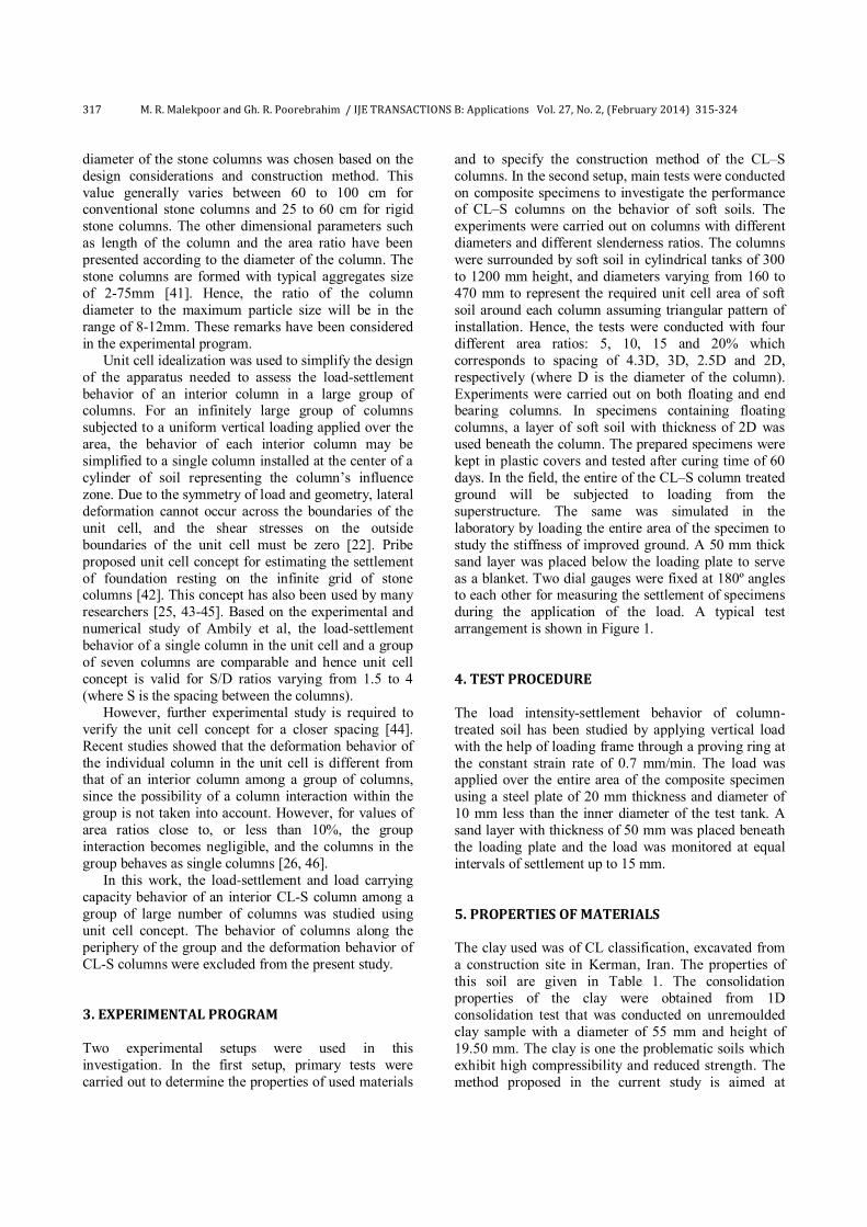
The experimental program was extended to evaluate the scale effect on the behavior of CL-S columns by varying the column diameter from 50 to 150 mm. Figure 6 indicates a relationship between load intensity and settlement for columns with area ratio equal to 10% and L/D=6. Figure 7 shows the variation of load carrying capacity (corresponding to 15 mm settlement) with variation of the column diameter.
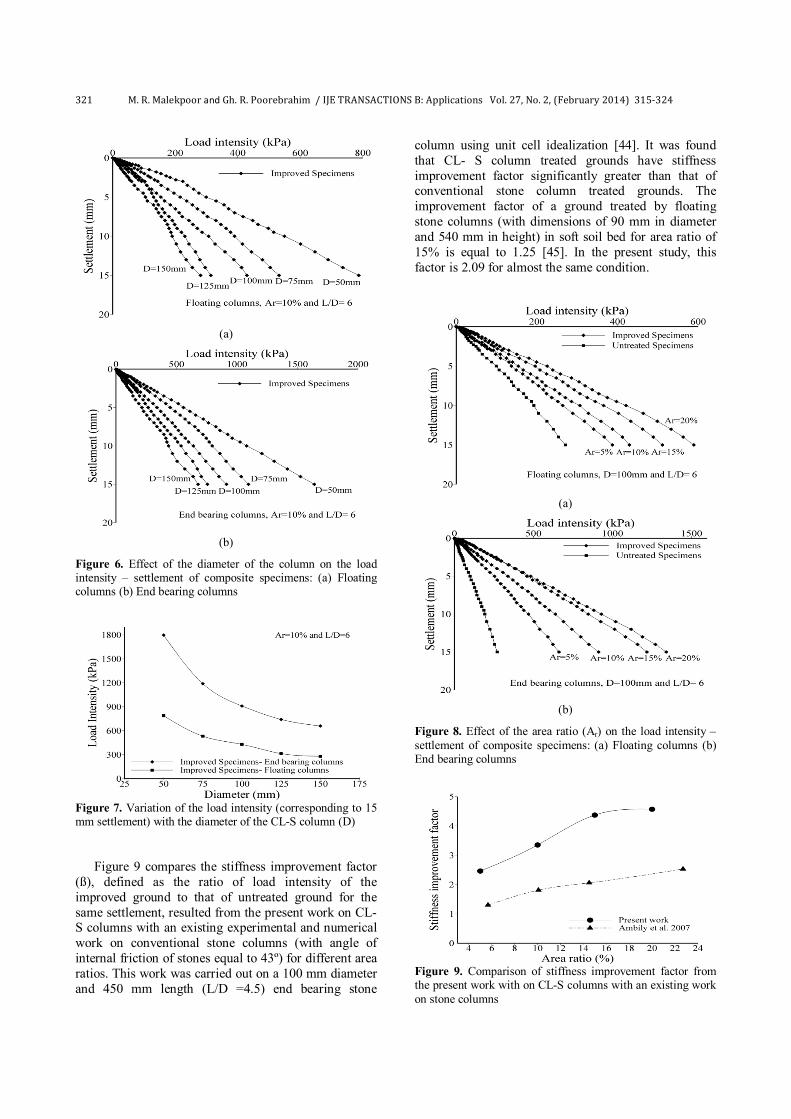
As predicted, the load carrying capacity decreases with increasing the diameter, and the variations of load carrying capacity of specimens reduces by increasing the size of the model. For instant, the change of the load intensity (corresponding to 15 mm settlement) for floating columns of 50 and 75 mm diameter is 32% and for columns with diameter of 125 mm and 150 mm is 11%. Since in practice, rigid stone columns are used with minimum diameter of 250 mm, the results of large scale tests can be applied to extrapolate and predict the full size behavior of these columns. Figure 8 illustrates the variation of load intensity versus settlement for different area ratios, L/D = 6 and D =100 mm. Comparing these results shows that CL-S columns increase the stiffness of soft soils, even for area ratio of 5% (which corresponds to spacing of 4.2D) and application of end bearing columns further improves the bearing capacity of soft soils. When the area ratio increases, load intensity of the specimens increases significantly. However, when the area ratio exceeds 15%, the increment rate of load intensity is decreased.
It should be noted that, for a significant improvement in bearing capacity using conventional stone columns, an area ratio of 25has been suggested [26]. For important projects, it is desired to carry out field trials to determine the most optimum spacing of columns with regard to the required bearing capacity of the soil, permissible settlement of the foundation, loading pattern, column dimensions, etc. Accordingly, rational decisions can be taken to tailor design of different types of stone columns installation to achieve maximum performance at optimum cost [3].
321 M. R. Malekpoor and Gh. R. Poorebrahim / IJE TRANSACTIONS B: Applications Vol. 27, No. 2, (February 2014) 315-324
(a)
(b)
Figure 6. Effect of the diameter of the column on the load intensity – settlement of composite specimens: (a) Floating columns (b) End bearing columns
Figure 7. Variation of the load intensity (corresponding to 15 mm settlement) with the diameter of the CL-S column (D)
Figure 9 compares the stiffness improvement factor (ß), defined as the ratio of load intensity of the improved ground to that of untreated ground for the same settlement, resulted from the present work on CL-S columns with an existing experimental and numerical work on conventional stone columns (with angle of internal friction of stones equal to 43º) for different area ratios. This work was carried out on a 100 mm diameter and 450 mm length (L/D =4.5) end bearing stone
column using unit cell idealization [44]. It was found that CL- S column treated grounds have stiffness improvement factor significantly greater than that of conventional stone column treated grounds. The improvement factor of a ground treated by floating stone columns (with dimensions of 90 mm in diameter and 540 mm in height) in soft soil bed for area ratio of 15% is equal to 1.25 [45]. In the present study, this factor is 2.09 for almost the same condition.
(a)
(b)
Figure 8. Effect of the area ratio (Ar) on the load intensity – settlement of composite specimens: (a) Floating columns (b) End bearing columns
Figure 9. Comparison of stiffness improvement factor from the present work with on CL-S columns with an existing work on stone columns

M. R. Malekpoor and Gh. R. Poorebrahim / IJE TRANSACTIONS B: Applications Vol. 27, No. 2, (February 2014) 315-324 322
8. CONCLUDING REMARKS Experimental investigation was carried out to study the load- settlement behavior of an interior CL–S column among a group of large number of columns in soft soils using unit cell concept. The model tests have been performed in the laboratory at single gravity and at corresponding low stress level. Based on the results and discussion presented, the following conclusion may be drawn: 1. The CL–S columns exhibit a stiffer and stronger
response compared to conventional stone columns installed in soft soils. These columns improve the load carrying capacity and reduce the settlement of such soils.
2. The results show that the load carrying capacity decreases by increasing the slenderness ratio and this ratio has significant influence on the behavior of end bearing columns.
3. Meaningful scale effect has been observed in the laboratory models, in such a way that the load carrying capacity decreases by increasing the size of models. However, for specimens containing columns with diameter greater than 100 mm and constant slenderness ratio, the variations of stiffness become negligible, i.e. the stiffness tends to converge to a fixed value and hence the results of large scale laboratory model tests can be used to predict the full size behavior of these columns with tolerable error. Nevertheless, for accurate conclusions, full scale tests can be recommended in future research efforts.
4. The performance of CL–S column is remarkably enhanced by increasing the area ratio. However, when the area ratio exceeds 15%, the rate of increment of the load carrying capacity is negligible.
5. Comparison of the results of present work with an existing experimental and numerical works on conventional stone columns show that CL-S column treated grounds have stiffness improvement factor significantly greater than that of conventional stone column treated grounds.
[1-48] 9. REFERENCES 1. Curtin, W., Shaw, G., Parkinson, G. and Golding, J., "Ground
improvement methods", Structural Foundation Designers' Manual, (2006) 124-139.
2. Malekpoor, M. R. and Toufigh, M. M., "Laboratory study of soft soil improvement using lime mortar-(well graded) soil columns", ASTM Geotechnical Testing Journal, Vol. 33, No. 3, (2010), 225-235.
3. Babu, M. D., Nayak, S. and Shivashankar, R., "A critical review of construction, analysis and behaviour of stone columns", Geotechnical and Geological Engineering, Vol. 31, No. 1, (2013), 1-22.
4. Han, J. and Ye, S., "Settlement analysis of buildings on the soft clays stabilized by stone columns", in Proc., Int. Conf. on Soil Improvement and Pile Found. Vol. 118, (1992), 446-451.
5. Mitchell, J. K. and Huber, T. R., "Performance of a stone column foundation", Journal of Geotechnical Engineering, Vol. 111, No. 2, (1985), 205-223.
6. Hamedi, A. and Marandi, S., "Laboratory studies on the effect of vertical gravel column drains on liquefaction potential", International Journal of Engineering, (2011).
7. Shivashankar, R., Babu, M. D., Nayak, S. and Manjunath, R., "Stone columns with vertical circumferential nails: Laboratory model study", Geotechnical and Geological Engineering, Vol. 28, No. 5, (2010), 695-706.
8. Engelhardt, K., Flynn, W. A. and Bayuk, A. A., "Vibro- replacement method to strengthen cohesive soils in situ", ASCE National Structural Engineering Meeting, Cincinnati, (1974).
9. DiMaggio, J. A., "Stone columns for highway construction", Technical Report No. FHWA-DP-46-1, U.S. Department of Transport, Federal Highway Administration, (1978).
10. Han, J. and Ye, S.-L., "Simplified method for consolidation rate of stone column reinforced foundations", Journal of Geotechnical and Geoenvironmental Engineering, Vol. 127, No. 7, (2001), 597-603.
11. McKelvey, D., Sivakumar, V., Bell, A. and Graham, J., "Modelling vibrated stone columns in soft clay", Proceedings of the ICE-Geotechnical Engineering, Vol. 157, No. 3, (2004), 137-149.
12. Castro, J. and Karstunen, M., "Numerical simulations of stone column installation", Canadian Geotechnical Journal, Vol. 47, No. 10, (2010), 1127-1138.
13. Murugesan, S. and Rajagopal, K., "Studies on the behavior of single and group of geosynthetic encased stone columns", Journal of Geotechnical and Geoenvironmental Engineering, Vol. 136, No. 1, (2009), 129-139.
14. Cimentada, A., Da Costa, A., Cañizal, J. and Sagaseta, C., "Laboratory study on radial consolidation and deformation in clay reinforced with stone columns", Canadian Geotechnical Journal, Vol. 48, No. 1, (2010), 36-52.
15. Deb, K., Samadhiya, N. K. and Namdeo, J. B., "Laboratory model studies on unreinforced and geogrid-reinforced sand bed over stone column-improved soft clay", Geotextiles and Geomembranes, Vol. 29, No. 2, (2011), 190-196.
16. Fattah, M. Y., Shlash, K. T. and Al-Waily, M. J. M., "Stress concentration ratio of model stone columns in soft clays", Geotechnical Testing Journal, Vol. 34, No. 1, (2011), 1.
17. Ayadat, T., Hanna, A. and Etezad, M., "Failure process of stone columns in collapsible soils", International Journal of Engineering-Transactions B: Applications, Vol. 21, No. 2, (2008), 135.
18. Sivakumar, V., McKelvey, D., Graham, J. and Hughes, D., "Triaxial tests on model sand columns in clay", Canadian Geotechnical Journal, Vol. 41, No. 2, (2004), 299-312.
19. Black, J., Sivakumar, V. and McKinley, J., "Performance of clay samples reinforced with vertical granular columns", Canadian Geotechnical Journal, Vol. 44, No. 1, (2007), 89-95.
20. Greenwood, D., "Mechanical improvement of soils below ground surface", in Inst Civil Engineers Proc, London/UK/. (1900).
21. Hughes, J. and Withers, N., "Reinforcing of soft cohesive soils with stone columns", Ground Engineering, Vol. 7, No. 3, (1974).
22. Barksdale, R. D. and Bachus, R. C., "Design and construction of stone columns" Vol. I. (1983).

323 M. R. Malekpoor and Gh. R. Poorebrahim / IJE TRANSACTIONS B: Applications Vol. 27, No. 2, (February 2014) 315-324 23. McKenna, J., Eyre, W. and Wolstenholme, D., "Performance of
an embankment supported by stone columns in soft ground", Géotechnique, Vol. 25, No. 1, (1975), 51-59.
24. Straßenwesen, F., "Merkblatt für untergrundverbesserung durch tiefenrüttler" (1979)
25. Gniel, J. and Bouazza, A., "Improvement of soft soils using geogrid encased stone columns", Geotextiles and Geomembranes, Vol. 27, No. 3, (2009), 167-175.
26. Wood, D. M., Hu, W. and Nash, D., "Group effects in stone column foundations: Model tests", Géotechnique, Vol. 50, No. 6, (2000), 689-698.
27. Mitra, S. and Chattopadhyay, B., "Stone columns and design limitations", in Proc. of Indian geotechnical conference, held at Culcutta, India. (1999), 201-205.
28. Samadhiya, N., Maheswari, P., Basu, P. and Kumar, M., "Load-settlement characteristics of granular piles with randomly mixed fibres", Indian Geotech Journal, Vol. 38, No. 3, (2008), 345-354.
29. Briançon, L., "Renforcement des sols par inclusions rigides—etat de l'art en france et à l'étranger", IREX, Paris, (2002).
30. SIMON, B., "General report–session 5–rigid inclusions and stone columns", in ISSMGE–TC 211 International Symposium on Ground Improvement. (2012).
31. Rathmayer, H., Piled embankment supported by single pile caps., Journal Article-Unidentified Source, (1975)
32. Combarieu, O., "Effet d'accrochage et methode d'evaluation du frottement negatif", Bull Liaison Lab Ponts Chauss, No. 71, (1974).
33. Combarieu, O., "Amelioration des sols par inclusions rigides verticales-application a l'edification de remblais sur sols mediocres", Rev Fr Geotech, No. 44, (1988).
34. Juran, I. and Riccobono, O., "Reinforcing soft soils with artificially cemented compacted-sand columns", Journal of Geotechnical Engineering, Vol. 117, No. 7, (1991), 1042-1060.
35. Broms, B. B. and Boman, P., "Lime columns-a new foundation method", Journal of Geotechnical and Geoenvironmental Engineering, Vol. 105, No. ASCE 14543, (1979).
36. Bell, F., "Stabilisation and treatment of clay soils with lime. Part 1-basic principles", Ground Engineering, Vol. 21, No. 1, (1988).
37. Locat, J., Trembaly, H. and Leroueil, S., "Mechanical and hydraulic behaviour of a soft inorganic clay treated with lime", Canadian Geotechnical Journal, Vol. 33, No. 4, (1996), 654-669.
38. Rao, S. N. and Rajasekaran, G., "Reaction products formed in lime-stabilized marine clays", Journal of Geotechnical Engineering, Vol. 122, No. 5, (1996), 329-336.
39. Zhou, C., Yin, J.-H. and Ming, J.-P., "Bearing capacity and settlement of weak fly ash ground improved using lime fly ash or stone columns", Canadian Geotechnical Journal, Vol. 39, No. 3, (2002), 585-596.
40. Rogers, C. D. F. and Bruce, C. J., "Slope stability engineering", Thomas Telford, London,, (1991).
41. 15284, I., "Indian standard code of practice for design and construction for ground improvement- guidelines", Part: 1, Stone Columns, India, (2003).
42. Priebe, H. J., "The design of vibro replacement", Ground Engineering, Vol. 28, No. 10, (1995), 31.
43. Alamgir, M., Miura, N., Poorooshasb, H. and Madhav, M., "Deformation analysis of soft ground reinforced by columnar inclusions", Computers and Geotechnics, Vol. 18, No. 4, (1996), 267-290.
44. Ambily, A. and Gandhi, S. R., "Behavior of stone columns based on experimental and fem analysis", Journal of Geotechnical and Geoenvironmental Engineering, Vol. 133, No. 4, (2007), 405-415.
45. Shivashankar, R., Babu, M. D., Nayak, S. and Rajathkumar, V., "Experimental studies on behaviour of stone columns in layered soils", Geotechnical and Geological Engineering, Vol. 29, No. 5, (2011), 749-757.
46. Hanna, A., Etezad, M. and Ayadat, T., "Mode of failure of a group of stone columns in soft soil", International Journal of Geomechanics, Vol. 13, No. 1, (2013), 87-96.
47. D2166, A., "Standard test method for unconfined compressive strength of cohesive soil", West Conshohocken, PA, (2000).
48. D1557, A., "Test method for laboratory compaction characteristics of soil using modified effort", West Conshohocken, PA, (2000).

M. R. Malekpoor and Gh. R. Poorebrahim / IJE TRANSACTIONS B: Applications Vol. 27, No. 2, (February 2014) 315-324 324
Behavior of Compacted Lime-soil Columns M. R. Malekpoor, Gh. R. Poorebrahim Department of Civil Engineering, University of Kerman, Kerman, Iran
P A P E R I N F O
Paper history: Received 11 June 2013 Received in revised form 10 September 2013 Accepted 14 September 2013
Keywords: Soft Clay Rigid Stone Column Lime Load Intensity Settlement
چکیده
هاي سنگی صلب از نوع شفته آهکی متراکم در اصالح ارزیابی رفتار ستونبراي آزمایشگاهی ي در این مقاله، نتایج یک مطالعهسلول صورت مرکب از ستون و خاك اطراف آن با استفاده از تئوري ها بهنمونه. هاي ریزدانه نرم ارائه شده استرفتار خاك
ها، نسبت طول به قطر آنها و نسبت قطر ستون: واحد در آزمایشگاه ساخته شده و با بررسی تاثیر پارامترهاي مختلف نظیر منظور تعیین ظرفیت به. اندتحت بارگذاري قرار گرفته) نسبت سطح مقطع ستون به سطح مقطع کل نمونه مرکب( مساحت
ها نشان نتایج آزمایش. ها، بارگذاري بر روي کل نمونه انجام شده استز این ستونهاي اصالح شده با استفاده اباربري زمینهاي ریزدانه میزان قابل توجهی موجب افزایش ظرفیت باربري و کاهش نشست خاكآهکی متراکم بههاي شفتهدهد که ستونمی
هاي حاوي ستون ر داشته و این تاثیر بر روي نمونههاي آزمایشگاهی نیز بر روي ظرفیت باربري آنها تاثیابعاد مدل. شوندنرم میها متر، تغییرات ظرفیت باربري ستونمیلی 100بیش از با افزایش قطر ستون به. باشدمتر قابل توجه میمیلی 100با قطر کمتر از
ها در کاربردهاي فتار این ستونبینی رتوان از نتایج آزمایشگاهی براي پیشپوشی بوده و بنابراین میبا تغییرات قطر، قابل چشمشده هاي سنگی متداول مقایسه در انتها نتایج مطالعات آزمایشگاهی با نتایج مطالعات قبلی در مورد ستون. کردعملی استفاده
. است
doi: 10.5829/idosi.ije.2014.27.02b.15
Copyright © 2022 FDOKUMEN