International Journal of Engineering Technology and ...
12
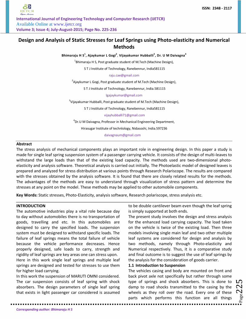
ISSN: 2348 - 2117 International Journal of Engineering Technology and Computer Research (IJETCR) Available Online at www.ijetcr.org Volume 3; Issue 4; July-August-2015; Page No. 225-236 Corresponding author: Bhimaraju H S Page225 Design and Analysis of Static Stresses for Leaf Springs using Photo-elasticity and Numerical Methods Bhimaraju H S 1 , Ajaykumar L Gogi 2 , Vijayakumar Hubballi 3 , Dr. U M Daivagna 4 1 Bhimaraju H S, Post graduate student of M.Tech (Machine Design), S T J Institute of Technology, Ranebennur, India581115 [email protected] 2 Ajaykumar L Gogi, Post graduate student of M.Tech (Machine Design), S T J Institute of Technology, Ranebennur, India.581115 [email protected] 3 Vijayakumar Hubballi, Post graduate student of M.Tech (Machine Design), S T J Institute of Technology, Ranebennur, India581115 [email protected] 4 Dr.U M Daivagna, Professor in Mechanical Engineering Department, Hirasugar Institute of technlology, Nidasoshi, India.597236 [email protected] Abstract The stress analysis of mechanical components plays an important role in engineering design. In this paper a study is made for single leaf spring suspension system of a passenger carrying vehicle. It consists of the design of multi-leaves to withstand the large loads than that of the existing load capacity. The methods used are two-dimensional photo- elasticity and analysis software. Theoretical analysis is carried out initially. The Photoelastic model of designed leaves is prepared and analyzed for stress distribution at various points through Research Polariscope. The results are compared with the stresses obtained by the analysis software. It is found that there are closely related results for the methods. The advantages of the methods are easy to understand through visualization of stress pattern and determine the stresses at any point on the model. These methods may be applied to other automobile components. Key Words: Static stresses, Photo-Elasticity, analysis software, Research polariscope, stress analysis etc. INTRODUCTION The automotive industries play a vital role because day to day without automobiles there is no transportation of goods, travelling and etc. In this automobiles are designed to carry the specified loads. The suspension system must be designed to withstand specific loads. The failure of leaf springs means the total failure of vehicle because the vehicle performance decreases. Hence properly designed, safe loads to carry, strength and rigidity of leaf springs are key areas one can stress upon. Here in this work single leaf springs and multiple leaf springs are designed and tested for stresses to use them for higher load carrying. In this work the suspension of MARUTI OMNI considered. The car suspension consists of leaf spring with shock absorbers. The design parameters of single leaf spring that exists in light passenger car considered is assumed to be double cantilever beam even though the leaf spring is simply supported at both ends. The present study involves the design and stress analysis for the enhanced load carrying capacity. The load taken on the vehicle is twice of the existing load. Then three models involving single main leaf and two other multiple leaf systems are considered for design and analysis by two methods, namely through Photo-elasticity and Numerical respectively. Thus, it is a comparative study and final outcome is to suggest the use of leaf springs by the analysis for the consideration of goods carrier. 1.1 Introduction to Suspension The vehicles casing and body are mounted on front and back pivot axle not specifically but rather through some type of springs and shock absorbers. This is done to damp to road shocks transmitted to the casing by the wheels as they roll over the road. Every one of these parts which performs this function are all things
-
Upload
khangminh22 -
Category
Documents
-
view
0 -
download
0
Transcript of International Journal of Engineering Technology and ...
ISSN: 2348 - 2117
International Journal of Engineering Technology and Computer Research (IJETCR) Available Online at www.ijetcr.org Volume 3; Issue 4; July-August-2015; Page No. 225-236
Corresponding author: Bhimaraju H S
Page
225
Design and Analysis of Static Stresses for Leaf Springs using Photo-elasticity and Numerical Methods
Bhimaraju H S1, Ajaykumar L Gogi2, Vijayakumar Hubballi3, Dr. U M Daivagna4 1Bhimaraju H S, Post graduate student of M.Tech (Machine Design),
S T J Institute of Technology, Ranebennur, India581115
[email protected] 2Ajaykumar L Gogi, Post graduate student of M.Tech (Machine Design),
S T J Institute of Technology, Ranebennur, India.581115
[email protected] 3Vijayakumar Hubballi, Post graduate student of M.Tech (Machine Design),
S T J Institute of Technology, Ranebennur, India581115
[email protected] 4Dr.U M Daivagna, Professor in Mechanical Engineering Department,
Hirasugar Institute of technlology, Nidasoshi, India.597236
Abstract The stress analysis of mechanical components plays an important role in engineering design. In this paper a study is made for single leaf spring suspension system of a passenger carrying vehicle. It consists of the design of multi-leaves to withstand the large loads than that of the existing load capacity. The methods used are two-dimensional photo-elasticity and analysis software. Theoretical analysis is carried out initially. The Photoelastic model of designed leaves is prepared and analyzed for stress distribution at various points through Research Polariscope. The results are compared with the stresses obtained by the analysis software. It is found that there are closely related results for the methods. The advantages of the methods are easy to understand through visualization of stress pattern and determine the stresses at any point on the model. These methods may be applied to other automobile components.
Key Words: Static stresses, Photo-Elasticity, analysis software, Research polariscope, stress analysis etc.
INTRODUCTION The automotive industries play a vital role because day to day without automobiles there is no transportation of goods, travelling and etc. In this automobiles are designed to carry the specified loads. The suspension system must be designed to withstand specific loads. The failure of leaf springs means the total failure of vehicle because the vehicle performance decreases. Hence properly designed, safe loads to carry, strength and rigidity of leaf springs are key areas one can stress upon. Here in this work single leaf springs and multiple leaf springs are designed and tested for stresses to use them for higher load carrying. In this work the suspension of MARUTI OMNI considered. The car suspension consists of leaf spring with shock absorbers. The design parameters of single leaf spring that exists in light passenger car considered is assumed
to be double cantilever beam even though the leaf spring is simply supported at both ends. The present study involves the design and stress analysis for the enhanced load carrying capacity. The load taken on the vehicle is twice of the existing load. Then three models involving single main leaf and two other multiple leaf systems are considered for design and analysis by two methods, namely through Photo-elasticity and Numerical respectively. Thus, it is a comparative study and final outcome is to suggest the use of leaf springs by the analysis for the consideration of goods carrier. 1.1 Introduction to Suspension The vehicles casing and body are mounted on front and back pivot axle not specifically but rather through some type of springs and shock absorbers. This is done to damp to road shocks transmitted to the casing by the wheels as they roll over the road. Every one of these parts which performs this function are all things

Bhimaraju H S et al. / International Journal of Engineering Technology and Computer Research (IJETCR)
© IJETCR. All Rights Reserved.
Page
226
Page
226
Page
226
Page
226
Page
226
Page
226
Page
226
Page
226
Page
226
Page
226
Page
226
Page
226
Page
226
Page
226
Page
226
Page
226
Page
226
Page
226
Page
226
Page
226
Page
226
considered called a suspension framework or suspension system. Consequently, the suspension system includes springs, shock absorbers and their mountings. The suspension system of a vehicle is separated into Rear end suspension and Front end suspension. [1] 1.2 Functions of Suspension System • To prevent the road shocks from being transmitted to the vehicle outline or frame. • To keep the soundness of the vehicle in pitching or moving, while in movement. • To safe monitor the occupation from road shocks. • To provide better road grip while driving, cornering and braking. • To provide proper controlling and steering geometry. 1.3 Introduction to Leaf Spring Leaf spring comprises of various leaves, made of steel plates, of expanding lengths from the middle. Every one of these leaves is clamped by a middle bolt at centre, and side clasps at sides so that the leaves are in position. Primary leaf is longest one having bowed finishes, called the spring eyes. The spring eye is associated with the edge by shackle. The middle segment of the spring is associated with the front hub by U-jolt. Leaf springs are of the fallowing sorts: 1. Semi curved spring. 2. Quarter curved leaf spring. 3. Three quarter curved spring. 4. Transverse spring. 5. Full curved spring. 6. Plat structure curved spring
1.4 Laminated Semi-Elliptic Spring
The Fig demonstrates an overlaid semi-elliptic spring. The top leaf is known as the main leaf. The eye is accommodated for attaching the spring with another machine part. The measure of twist that is given to the spring from the central line, going through the eyes, is known as camber. The camber is given so that even at the most extreme load the deflected spring should not touch the machine part to which it is connected. The
camber indicated in the figure is known as positive camber. The central clamp is required to hold the leaves of the spring. Be that as it may, the bolt holes needed to connect with the bolts to clamp the leaves weaken the spring to some degree. Bounce back clips help to share the load from the master leaf to the graduated leaf. 1.5 Objectives of the Project Work The main objective of the project is to design and analysis of stress of leaf springs to enhance the load carrying capacity. For this MARUTI OMNI vehicle is chosen. The load is enhanced to twice so as to enable to use it as a goods carrier vehicle. Hence the objectives of the project are, • To design and check the induced stresses for single, double and multiple leaf springs. • To fabricate the photo elastic models for stress analysis using research polariscope. • To model single, double and multiple leaf springs and analysis for stress using numerical method such as ANSYS 12. • To compare the obtained results. • To draw conclusions. • To suggest the applications of the project workits use for industrial application. 2 Reviews of Papers on Leaf Spring 2.1 Berger, B. Kaiser et al. [2] These authors have done a long haul fatigue tests on shot peened helical pressure springs were directed by method for an uncommon spring exhaustion testing machine at 40Hz. Test springs were made of three distinctive spring materials-oil solidified and tempered SiCr-and SiCrV-alloyed valve spring steel and stainless steel up to 500 spring with a wire measurement of d = 3.0 mm or 900 spring with d = 1.6 mm were tried at diverse anxiety levels. Technique to be utilized trial system the VHCF-test on distinctive wire breadth of spring. The paper incorporates a correlation of the consequence of the distinctive spring sizes, materials, number of cycles and shot peeling conditions and frameworks further examinations in the VHCF-locale. 2.2 Jadhav Mahesh V. et. al.[3] These authors have completed the correlation between ANSYS software results and results acquired by analytical solution. The goal is to analyze the load carrying capacity, stiffness and weight savings of composite leaf spring with that of steel leaf spring. From the relative study, it is seen that the composite leaf spring are higher and more practical than convectional leaf spring. After drawn out utilization of ordinary metal Coil Spring, its quality lessens and vehicle begins running posterior down furthermore hits on the knock plugs (i.e.
Bhimaraju H S et al. / International Journal of Engineering Technology and Computer Research (IJETCR)
© IJETCR. All Rights Reserved.
Page
227
Page
227
Page
227
Page
227
Page
227
Page
227
Page
227
Page
227
Page
227
Page
227
Page
227
Page
227
Page
227
Page
227
Page
227
Page
227
Page
227
Page
227
Page
227
Page
227
Page
227
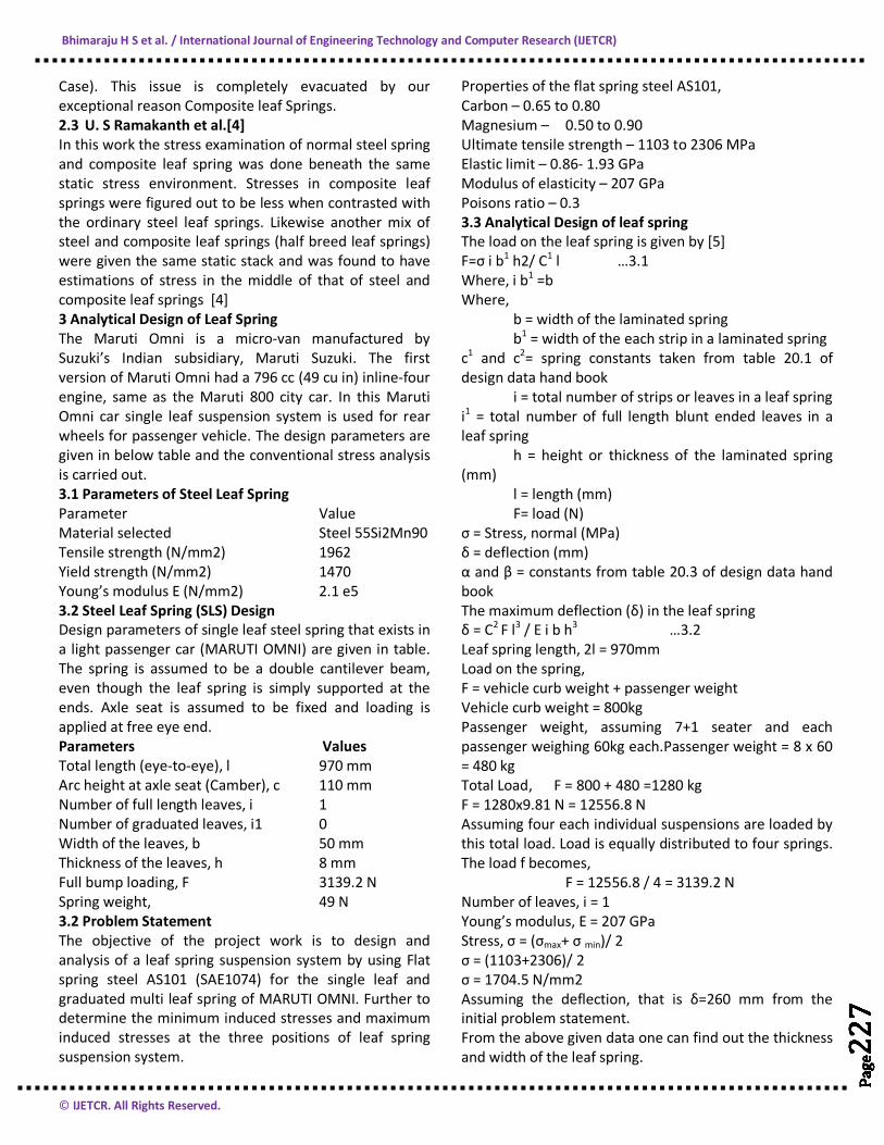
Case). This issue is completely evacuated by our exceptional reason Composite leaf Springs. 2.3 U. S Ramakanth et al.[4] In this work the stress examination of normal steel spring and composite leaf spring was done beneath the same static stress environment. Stresses in composite leaf springs were figured out to be less when contrasted with the ordinary steel leaf springs. Likewise another mix of steel and composite leaf springs (half breed leaf springs) were given the same static stack and was found to have estimations of stress in the middle of that of steel and composite leaf springs [4] 3 Analytical Design of Leaf Spring The Maruti Omni is a micro-van manufactured by Suzuki’s Indian subsidiary, Maruti Suzuki. The first version of Maruti Omni had a 796 cc (49 cu in) inline-four engine, same as the Maruti 800 city car. In this Maruti Omni car single leaf suspension system is used for rear wheels for passenger vehicle. The design parameters are given in below table and the conventional stress analysis is carried out. 3.1 Parameters of Steel Leaf Spring Parameter Value Material selected Steel 55Si2Mn90 Tensile strength (N/mm2) 1962 Yield strength (N/mm2) 1470 Young’s modulus E (N/mm2) 2.1 e5 3.2 Steel Leaf Spring (SLS) Design Design parameters of single leaf steel spring that exists in a light passenger car (MARUTI OMNI) are given in table. The spring is assumed to be a double cantilever beam, even though the leaf spring is simply supported at the ends. Axle seat is assumed to be fixed and loading is applied at free eye end. Parameters Values Total length (eye-to-eye), l 970 mm Arc height at axle seat (Camber), c 110 mm Number of full length leaves, i 1 Number of graduated leaves, i1 0 Width of the leaves, b 50 mm Thickness of the leaves, h 8 mm Full bump loading, F 3139.2 N Spring weight, 49 N 3.2 Problem Statement The objective of the project work is to design and analysis of a leaf spring suspension system by using Flat spring steel AS101 (SAE1074) for the single leaf and graduated multi leaf spring of MARUTI OMNI. Further to determine the minimum induced stresses and maximum induced stresses at the three positions of leaf spring suspension system.
Properties of the flat spring steel AS101, Carbon – 0.65 to 0.80 Magnesium – 0.50 to 0.90 Ultimate tensile strength – 1103 to 2306 MPa Elastic limit – 0.86- 1.93 GPa Modulus of elasticity – 207 GPa Poisons ratio – 0.3 3.3 Analytical Design of leaf spring The load on the leaf spring is given by [5] F=σ i b1 h2/ C1 l …3.1 Where, i b1 =b Where, b = width of the laminated spring b1 = width of the each strip in a laminated spring c1 and c2= spring constants taken from table 20.1 of design data hand book i = total number of strips or leaves in a leaf spring i1 = total number of full length blunt ended leaves in a leaf spring h = height or thickness of the laminated spring (mm) l = length (mm) F= load (N) σ = Stress, normal (MPa) δ = deflection (mm) α and β = constants from table 20.3 of design data hand book The maximum deflection (δ) in the leaf spring δ = C2 F l3 / E i b h3 …3.2 Leaf spring length, 2l = 970mm Load on the spring, F = vehicle curb weight + passenger weight Vehicle curb weight = 800kg Passenger weight, assuming 7+1 seater and each passenger weighing 60kg each.Passenger weight = 8 x 60 = 480 kg Total Load, F = 800 + 480 =1280 kg F = 1280x9.81 N = 12556.8 N Assuming four each individual suspensions are loaded by this total load. Load is equally distributed to four springs. The load f becomes, F = 12556.8 / 4 = 3139.2 N Number of leaves, i = 1 Young’s modulus, E = 207 GPa Stress, σ = (σmax+ σ min)/ 2 σ = (1103+2306)/ 2 σ = 1704.5 N/mm2 Assuming the deflection, that is δ=260 mm from the initial problem statement. From the above given data one can find out the thickness and width of the leaf spring.
Bhimaraju H S et al. / International Journal of Engineering Technology and Computer Research (IJETCR)
© IJETCR. All Rights Reserved.
Page
228
Page
228
Page
228
Page
228
Page
228
Page
228
Page
228
Page
228
Page
228
Page
228
Page
228
Page
228
Page
228
Page
228
Page
228
Page
228
Page
228
Page
228
Page
228
Page
228
Page
228
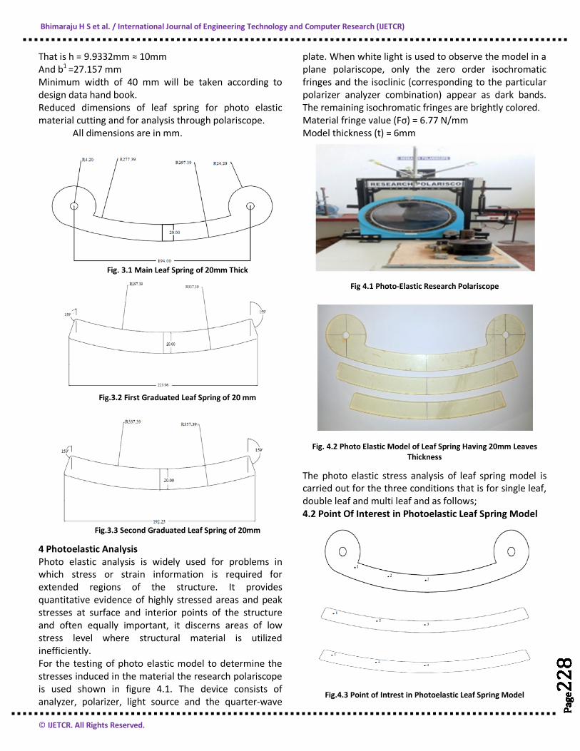
That is h = 9.9332mm ≈ 10mm And b1 =27.157 mm Minimum width of 40 mm will be taken according to design data hand book. Reduced dimensions of leaf spring for photo elastic material cutting and for analysis through polariscope. All dimensions are in mm.
Fig. 3.1 Main Leaf Spring of 20mm Thick
Fig.3.2 First Graduated Leaf Spring of 20 mm
Fig.3.3 Second Graduated Leaf Spring of 20mm
4 Photoelastic Analysis Photo elastic analysis is widely used for problems in which stress or strain information is required for extended regions of the structure. It provides quantitative evidence of highly stressed areas and peak stresses at surface and interior points of the structure and often equally important, it discerns areas of low stress level where structural material is utilized inefficiently. For the testing of photo elastic model to determine the stresses induced in the material the research polariscope is used shown in figure 4.1. The device consists of analyzer, polarizer, light source and the quarter-wave
plate. When white light is used to observe the model in a plane polariscope, only the zero order isochromatic fringes and the isoclinic (corresponding to the particular polarizer analyzer combination) appear as dark bands. The remaining isochromatic fringes are brightly colored. Material fringe value (Fσ) = 6.77 N/mm Model thickness (t) = 6mm
Fig 4.1 Photo-Elastic Research Polariscope
Fig. 4.2 Photo Elastic Model of Leaf Spring Having 20mm Leaves Thickness
The photo elastic stress analysis of leaf spring model is carried out for the three conditions that is for single leaf, double leaf and multi leaf and as follows; 4.2 Point Of Interest in Photoelastic Leaf Spring Model
Fig.4.3 Point of Intrest in Photoelastic Leaf Spring Model
Bhimaraju H S et al. / International Journal of Engineering Technology and Computer Research (IJETCR)
© IJETCR. All Rights Reserved.
Page
229
Page
229
Page
229
Page
229
Page
229
Page
229
Page
229
Page
229
Page
229
Page
229
Page
229
Page
229
Page
229
Page
229
Page
229
Page
229
Page
229
Page
229
Page
229
Page
229
Page
229
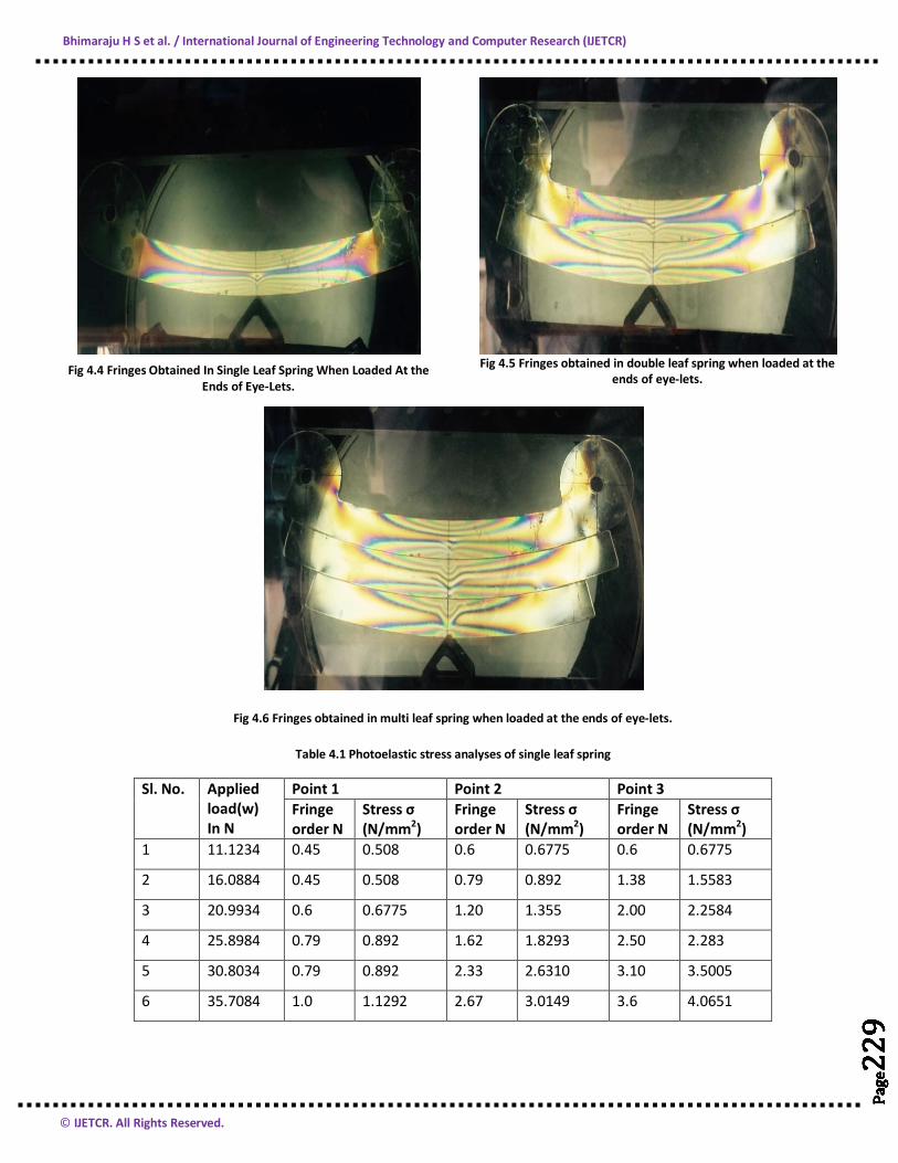
Fig 4.4 Fringes Obtained In Single Leaf Spring When Loaded At the Ends of Eye-Lets.
Fig 4.5 Fringes obtained in double leaf spring when loaded at the
ends of eye-lets.
Fig 4.6 Fringes obtained in multi leaf spring when loaded at the ends of eye-lets.
Table 4.1 Photoelastic stress analyses of single leaf spring
Sl. No.
Applied load(w) In N
Point 1 Point 2 Point 3 Fringe order N
Stress σ (N/mm2)
Fringe order N
Stress σ (N/mm2)
Fringe order N
Stress σ (N/mm2)
1 11.1234 0.45 0.508 0.6 0.6775 0.6 0.6775
2 16.0884 0.45 0.508 0.79 0.892 1.38 1.5583
3 20.9934 0.6 0.6775 1.20 1.355 2.00 2.2584
4 25.8984 0.79 0.892 1.62 1.8293 2.50 2.283
5 30.8034 0.79 0.892 2.33 2.6310 3.10 3.5005
6 35.7084 1.0 1.1292 2.67 3.0149 3.6 4.0651
Bhimaraju H S et al. / International Journal of Engineering Technology and Computer Research (IJETCR)
© IJETCR. All Rights Reserved.
Page
230
Page
230
Page
230
Page
230
Page
230
Page
230
Page
230
Page
230
Page
230
Page
230
Page
230
Page
230
Page
230
Page
230
Page
230
Page
230
Page
230
Page
230
Page
230
Page
230
Page
230
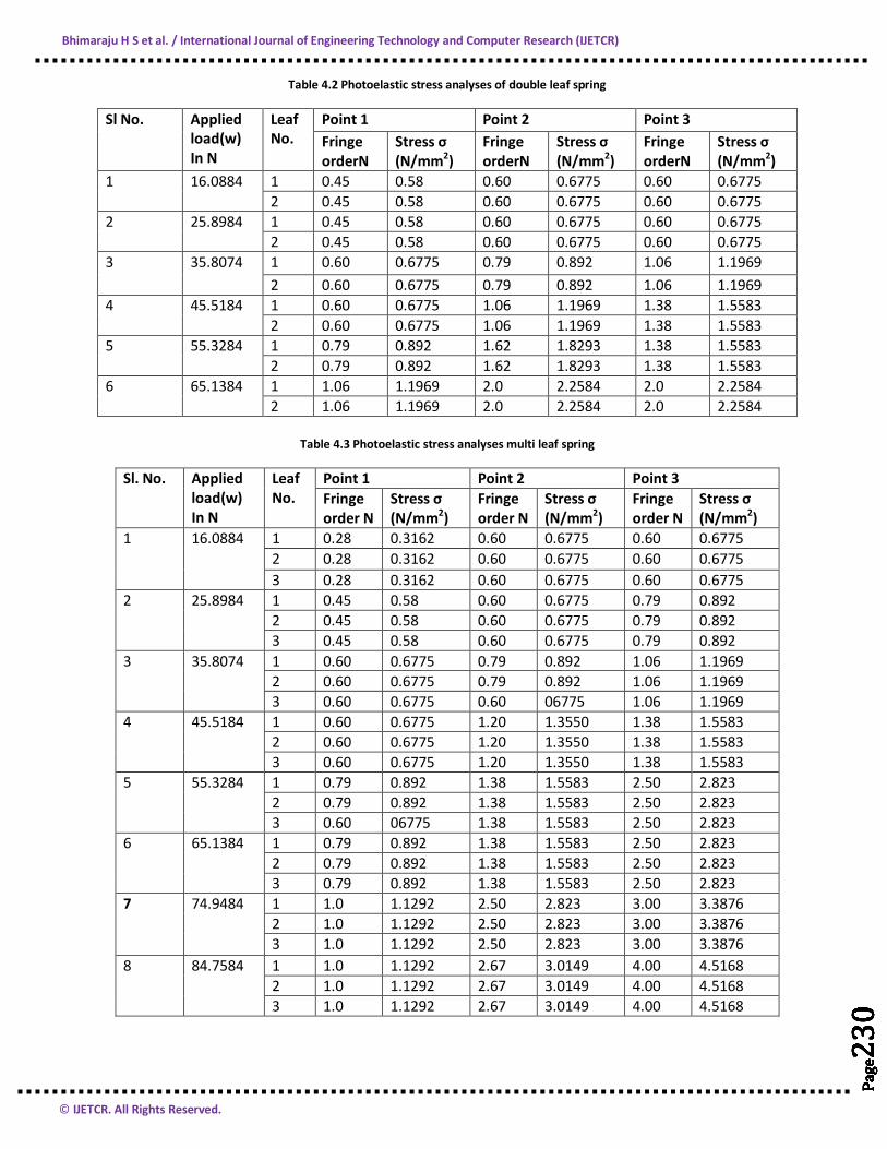
Table 4.2 Photoelastic stress analyses of double leaf spring
Sl No. Applied load(w) In N
Leaf No.
Point 1 Point 2 Point 3 Fringe orderN
Stress σ (N/mm2)
Fringe orderN
Stress σ (N/mm2)
Fringe orderN
Stress σ (N/mm2)
1 16.0884 1 0.45 0.58 0.60 0.6775 0.60 0.6775 2 0.45 0.58 0.60 0.6775 0.60 0.6775
2 25.8984 1 0.45 0.58 0.60 0.6775 0.60 0.6775 2 0.45 0.58 0.60 0.6775 0.60 0.6775
3 35.8074 1 0.60 0.6775 0.79 0.892 1.06 1.1969 2 0.60 0.6775 0.79 0.892 1.06 1.1969
4 45.5184 1 0.60 0.6775 1.06 1.1969 1.38 1.5583 2 0.60 0.6775 1.06 1.1969 1.38 1.5583
5 55.3284 1 0.79 0.892 1.62 1.8293 1.38 1.5583 2 0.79 0.892 1.62 1.8293 1.38 1.5583
6 65.1384 1 1.06 1.1969 2.0 2.2584 2.0 2.2584 2 1.06 1.1969 2.0 2.2584 2.0 2.2584
Table 4.3 Photoelastic stress analyses multi leaf spring
Sl. No. Applied
load(w) In N
Leaf No.
Point 1 Point 2 Point 3 Fringe order N
Stress σ (N/mm2)
Fringe order N
Stress σ (N/mm2)
Fringe order N
Stress σ (N/mm2)
1 16.0884 1 0.28 0.3162 0.60 0.6775 0.60 0.6775 2 0.28 0.3162 0.60 0.6775 0.60 0.6775 3 0.28 0.3162 0.60 0.6775 0.60 0.6775
2 25.8984 1 0.45 0.58 0.60 0.6775 0.79 0.892 2 0.45 0.58 0.60 0.6775 0.79 0.892 3 0.45 0.58 0.60 0.6775 0.79 0.892
3 35.8074 1 0.60 0.6775 0.79 0.892 1.06 1.1969 2 0.60 0.6775 0.79 0.892 1.06 1.1969 3 0.60 0.6775 0.60 06775 1.06 1.1969
4 45.5184 1 0.60 0.6775 1.20 1.3550 1.38 1.5583 2 0.60 0.6775 1.20 1.3550 1.38 1.5583 3 0.60 0.6775 1.20 1.3550 1.38 1.5583
5 55.3284 1 0.79 0.892 1.38 1.5583 2.50 2.823 2 0.79 0.892 1.38 1.5583 2.50 2.823 3 0.60 06775 1.38 1.5583 2.50 2.823
6 65.1384 1 0.79 0.892 1.38 1.5583 2.50 2.823 2 0.79 0.892 1.38 1.5583 2.50 2.823 3 0.79 0.892 1.38 1.5583 2.50 2.823
7 74.9484 1 1.0 1.1292 2.50 2.823 3.00 3.3876 2 1.0 1.1292 2.50 2.823 3.00 3.3876 3 1.0 1.1292 2.50 2.823 3.00 3.3876
8 84.7584 1 1.0 1.1292 2.67 3.0149 4.00 4.5168 2 1.0 1.1292 2.67 3.0149 4.00 4.5168 3 1.0 1.1292 2.67 3.0149 4.00 4.5168
Bhimaraju H S et al. / International Journal of Engineering Technology and Computer Research (IJETCR)
© IJETCR. All Rights Reserved.
Page
231
Page
231
Page
231
Page
231
Page
231
Page
231
Page
231
Page
231
Page
231
Page
231
Page
231
Page
231
Page
231
Page
231
Page
231
Page
231
Page
231
Page
231
Page
231
Page
231
Page
231
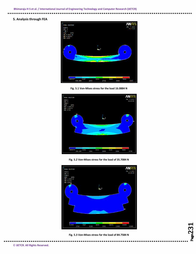
5. Analysis through FEA
Fig. 5.1 Von-Mises stress for the load 16.0884 N
Fig. 5.2 Von-Mises stress for the load of 35.7084 N
Fig. 5.3 Von-Mises stress for the load of 84.7584 N
Bhimaraju H S et al. / International Journal of Engineering Technology and Computer Research (IJETCR)
© IJETCR. All Rights Reserved.
Page
232
Page
232
Page
232
Page
232
Page
232
Page
232
Page
232
Page
232
Page
232
Page
232
Page
232
Page
232
Page
232
Page
232
Page
232
Page
232
Page
232
Page
232
Page
232
Page
232
Page
232
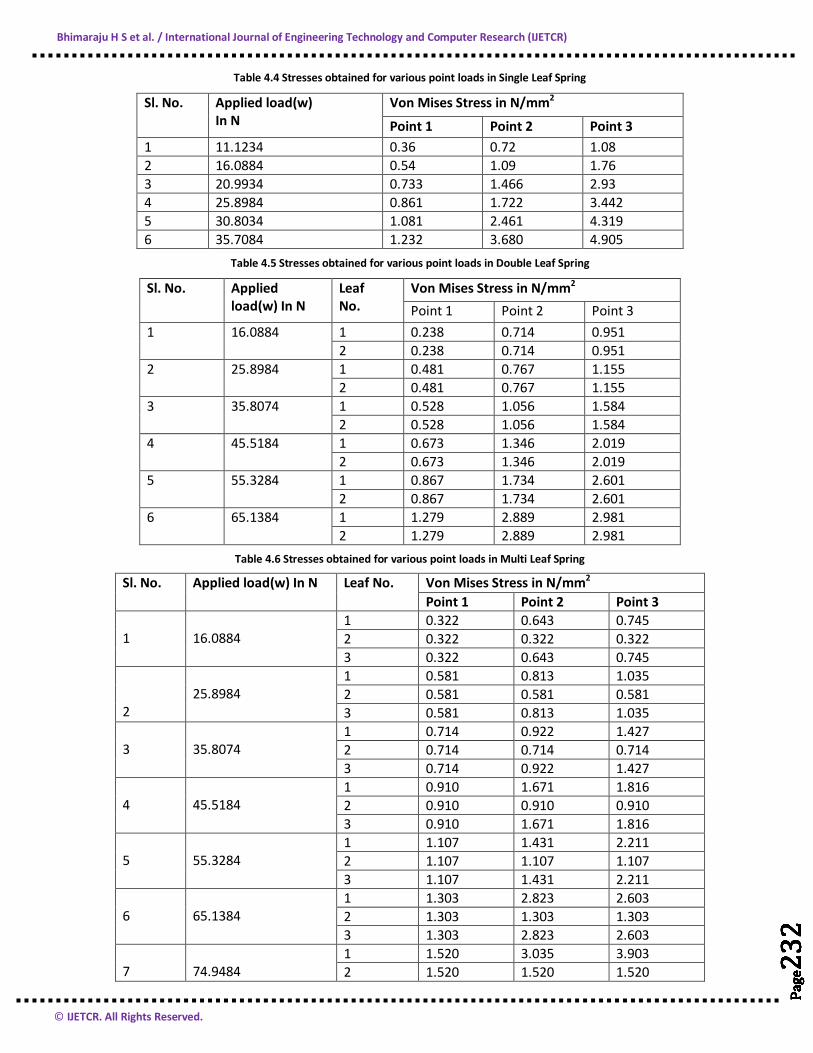
Table 4.4 Stresses obtained for various point loads in Single Leaf Spring
Sl. No. Applied load(w) In N
Von Mises Stress in N/mm2
Point 1 Point 2 Point 3 1 11.1234 0.36 0.72 1.08 2 16.0884 0.54 1.09 1.76 3 20.9934 0.733 1.466 2.93 4 25.8984 0.861 1.722 3.442 5 30.8034 1.081 2.461 4.319 6 35.7084 1.232 3.680 4.905
Table 4.5 Stresses obtained for various point loads in Double Leaf Spring
Sl. No. Applied load(w) In N
Leaf No.
Von Mises Stress in N/mm2 Point 1 Point 2 Point 3
1 16.0884 1 0.238 0.714 0.951 2 0.238 0.714 0.951
2 25.8984 1 0.481 0.767 1.155 2 0.481 0.767 1.155
3 35.8074 1 0.528 1.056 1.584 2 0.528 1.056 1.584
4 45.5184 1 0.673 1.346 2.019 2 0.673 1.346 2.019
5 55.3284 1 0.867 1.734 2.601 2 0.867 1.734 2.601
6 65.1384 1 1.279 2.889 2.981 2 1.279 2.889 2.981
Table 4.6 Stresses obtained for various point loads in Multi Leaf Spring
Sl. No. Applied load(w) In N Leaf No. Von Mises Stress in N/mm2 Point 1 Point 2 Point 3
1
16.0884
1 0.322 0.643 0.745 2 0.322 0.322 0.322 3 0.322 0.643 0.745
2
25.8984
1 0.581 0.813 1.035 2 0.581 0.581 0.581 3 0.581 0.813 1.035
3
35.8074
1 0.714 0.922 1.427 2 0.714 0.714 0.714 3 0.714 0.922 1.427
4
45.5184
1 0.910 1.671 1.816 2 0.910 0.910 0.910 3 0.910 1.671 1.816
5
55.3284
1 1.107 1.431 2.211 2 1.107 1.107 1.107 3 1.107 1.431 2.211
6
65.1384
1 1.303 2.823 2.603 2 1.303 1.303 1.303 3 1.303 2.823 2.603
7
74.9484
1 1.520 3.035 3.903 2 1.520 1.520 1.520
Bhimaraju H S et al. / International Journal of Engineering Technology and Computer Research (IJETCR)
© IJETCR. All Rights Reserved.
Page
233
Page
233
Page
233
Page
233
Page
233
Page
233
Page
233
Page
233
Page
233
Page
233
Page
233
Page
233
Page
233
Page
233
Page
233
Page
233
Page
233
Page
233
Page
233
Page
233
Page
233
3 1.520 3.035 3.903 8
84.7584
1 1.716 3.427 5.138 2 1.716 1.716 1.716 3 1.716 3.427 5.138
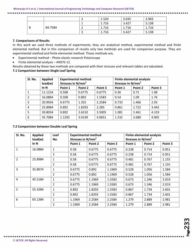
7. Comparisons of Results In this work we used three methods of experiments; they are analytical method, experimental method and finite elemental method. But in this comparison of results only two methods are used for comparison purpose. They are experimental method and finite elemental method. Those methods are, • Experimental method – Photo elastic research Polariscope • Finite elemental analysis – ANSYS-12. Results obtained by these two methods are compared with their stresses and relevant tables are tabulated. 7.1 Comparision between Single Leaf Spring
Sl. No. Applied load(w) In N
Experimental method Stresses in N/mm2
Finite elemental analysis Stresses in N/mm2
Point 1 Point 2 Point 3 Point 1 Point 2 Point 3 1 11.1234 0.508 0.6775 0.6775 0.36 0.72 1.08 2 16.0884 0.508 0.892 1.5583 0.54 1.09 1.76 3 20.9934 0.6775 1.355 2.2584 0.733 1.466 2.93 4 25.8984 0.892 1.8293 2.283 0.861 1.722 3.442 5 30.8034 0.892 2.6310 3.5005 1.081 2.461 4.319 6 35.7084 1.1292 3.0149 4.0651 1.232 3.680 4.905
7.2 Comparision between Double Leaf Spring
Sl. No. Applied load(w) In N
Leaf No.
Experimental method Stresses in N/mm2
Finite elemental analysis Stresses in N/mm2
Point 1 Point 2 Point 3 Point 1 Point 2 Point 3
1 16.0884 1 0.58 0.6775 0.6775 0.238 0.714 0.951 2 0.58 0.6775 0.6775 0.238 0.714 0.951
2 25.8984 1 0.58 0.6775 0.6775 0.481 0.767 1.155 2 0.58 0.6775 0.6775 0.481 0.767 1.155
3 35.8074 1 0.6775 0.892 1.1969 0.528 1.056 1.584 2 0.6775 0.892 1.1969 0.528 1.056 1.584
4 45.5184 1 0.6775 1.1969 1.5583 0.673 1.346 2.019 2 0.6775 1.1969 1.5583 0.673 1.346 2.019
5 55.3284 1 0.892 1.8293 1.5583 0.867 1.734 2.601 2 0.892 1.8293 1.5583 0.867 1.734 2.601
6 65.1384 1 1.1969 2.2584 2.2584 1.279 2.889 2.981 2 1.1969 2.2584 2.2584 1.279 2.889 2.981
Bhimaraju H S et al. / International Journal of Engineering Technology and Computer Research (IJETCR)
© IJETCR. All Rights Reserved.
Page
234
Page
234
Page
234
Page
234
Page
234
Page
234
Page
234
Page
234
Page
234
Page
234
Page
234
Page
234
Page
234
Page
234
Page
234
Page
234
Page
234
Page
234
Page
234
Page
234
Page
234
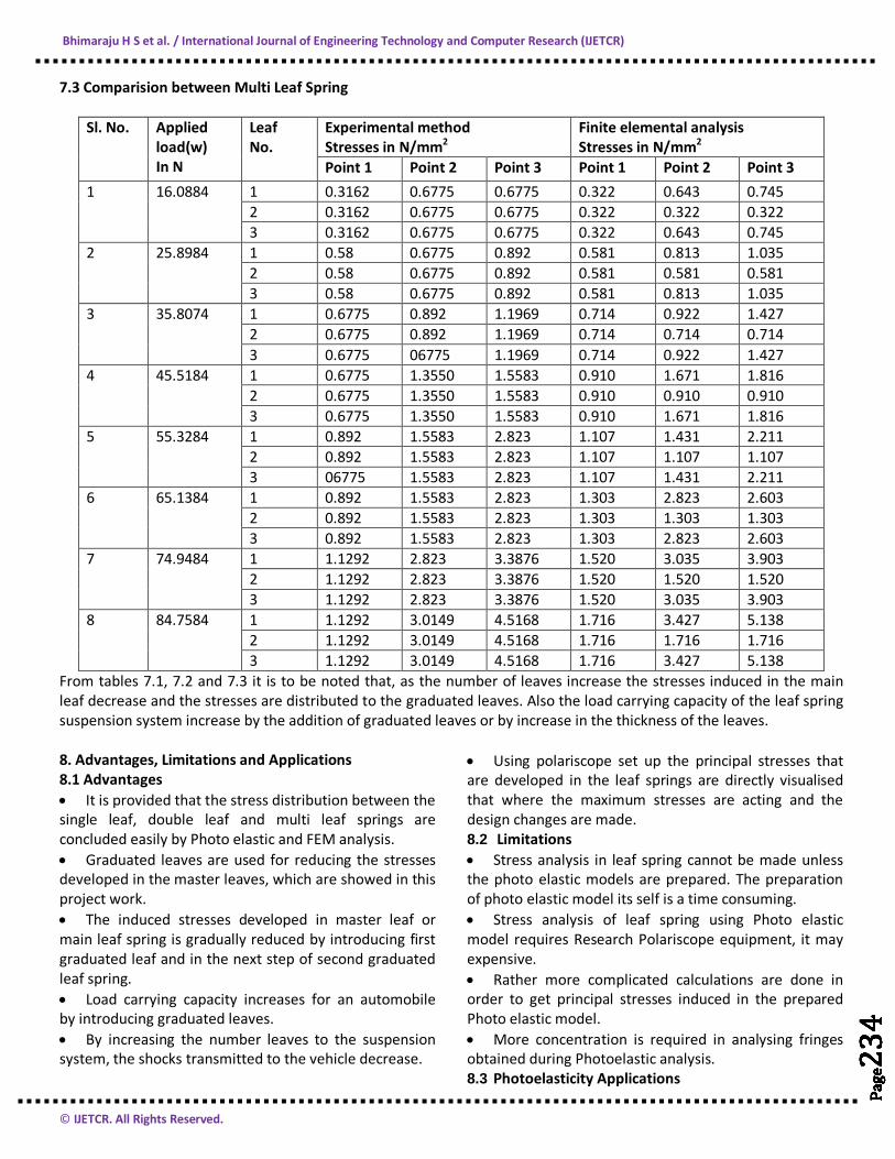
7.3 Comparision between Multi Leaf Spring
Sl. No. Applied load(w) In N
Leaf No.
Experimental method Stresses in N/mm2
Finite elemental analysis Stresses in N/mm2
Point 1 Point 2 Point 3 Point 1 Point 2 Point 3 1 16.0884 1 0.3162 0.6775 0.6775 0.322 0.643 0.745
2 0.3162 0.6775 0.6775 0.322 0.322 0.322 3 0.3162 0.6775 0.6775 0.322 0.643 0.745
2 25.8984 1 0.58 0.6775 0.892 0.581 0.813 1.035 2 0.58 0.6775 0.892 0.581 0.581 0.581 3 0.58 0.6775 0.892 0.581 0.813 1.035
3 35.8074 1 0.6775 0.892 1.1969 0.714 0.922 1.427 2 0.6775 0.892 1.1969 0.714 0.714 0.714 3 0.6775 06775 1.1969 0.714 0.922 1.427
4 45.5184 1 0.6775 1.3550 1.5583 0.910 1.671 1.816 2 0.6775 1.3550 1.5583 0.910 0.910 0.910 3 0.6775 1.3550 1.5583 0.910 1.671 1.816
5 55.3284 1 0.892 1.5583 2.823 1.107 1.431 2.211 2 0.892 1.5583 2.823 1.107 1.107 1.107 3 06775 1.5583 2.823 1.107 1.431 2.211
6 65.1384 1 0.892 1.5583 2.823 1.303 2.823 2.603 2 0.892 1.5583 2.823 1.303 1.303 1.303 3 0.892 1.5583 2.823 1.303 2.823 2.603
7 74.9484 1 1.1292 2.823 3.3876 1.520 3.035 3.903 2 1.1292 2.823 3.3876 1.520 1.520 1.520 3 1.1292 2.823 3.3876 1.520 3.035 3.903
8 84.7584 1 1.1292 3.0149 4.5168 1.716 3.427 5.138 2 1.1292 3.0149 4.5168 1.716 1.716 1.716 3 1.1292 3.0149 4.5168 1.716 3.427 5.138
From tables 7.1, 7.2 and 7.3 it is to be noted that, as the number of leaves increase the stresses induced in the main leaf decrease and the stresses are distributed to the graduated leaves. Also the load carrying capacity of the leaf spring suspension system increase by the addition of graduated leaves or by increase in the thickness of the leaves. 8. Advantages, Limitations and Applications 8.1 Advantages • It is provided that the stress distribution between the single leaf, double leaf and multi leaf springs are concluded easily by Photo elastic and FEM analysis. • Graduated leaves are used for reducing the stresses developed in the master leaves, which are showed in this project work. • The induced stresses developed in master leaf or main leaf spring is gradually reduced by introducing first graduated leaf and in the next step of second graduated leaf spring. • Load carrying capacity increases for an automobile by introducing graduated leaves. • By increasing the number leaves to the suspension system, the shocks transmitted to the vehicle decrease.
• Using polariscope set up the principal stresses that are developed in the leaf springs are directly visualised that where the maximum stresses are acting and the design changes are made. 8.2 Limitations • Stress analysis in leaf spring cannot be made unless the photo elastic models are prepared. The preparation of photo elastic model its self is a time consuming. • Stress analysis of leaf spring using Photo elastic model requires Research Polariscope equipment, it may expensive. • Rather more complicated calculations are done in order to get principal stresses induced in the prepared Photo elastic model. • More concentration is required in analysing fringes obtained during Photoelastic analysis. 8.3 Photoelasticity Applications
Bhimaraju H S et al. / International Journal of Engineering Technology and Computer Research (IJETCR)
© IJETCR. All Rights Reserved.
Page
235
Page
235
Page
235
Page
235
Page
235
Page
235
Page
235
Page
235
Page
235
Page
235
Page
235
Page
235
Page
235
Page
235
Page
235
Page
235
Page
235
Page
235
Page
235
Page
235
Page
235
• Stress analysis of any automobile components can be made using 2D and 3D photo elasticity. • Photo elasticity can be used in stress analysis of assembly components. 9. Conclusions and Future Scope 9.1 Conclusion • The development of Photo elastic leaf spring model having single leaf, double leaves and multi leaves are experimentally investigated for stress distribution in the leaves. • It may me concluded from the results obtained during experimental and finite elemental analysis that, stresses developed in the single leaf as a suspension system in automobile is having maximum value. • When another graduated leaves added to the same automobile vehicle decrease the stresses induced in the main leaf and the stresses are equally distributed in both the leaves. • By adding another graduated leaves to the suspension system enriches the load carrying capacity of the vehicle. • The results found by FEM method is nearly equal to results found by photo elastic experimental method. Also, • Load carrying capacity of vehicle increase by increase in the number of leaves and by increasing the thickness of the leaf spring suspension system. • From the present work one can decide where the maximum induced stresses are acting. Thus the chances of failure of the leaf spring suspension system are decided. • Centre of the leaf spring suspension system bearing maximum load of the vehicle and also it is having large deflection. 9.2 Future Scope The following are the future scopes of the leaf spring analysis by photo elasticity, • In this present work, reduced dimensions of leaf spring suspension system is used for the analysis purpose because of availability of instrument. Further the analysis can be made according to the exact dimensions of the parts using required experimental setups.
• The thickness of the leaf spring and the number of graduated leaf springs are increased for the analysis purpose using experimental and FEA tools. • 3D models with 3D Photo elastic research polariscope may be used for analysis purpose in future for getting exact results. References 1. J.E.Shigley and C.R.Mischke, Mechanical Engineering
Dsign, McGraw Hill Publication, 5th Edition, 1989. 2. U. S. Ramakanth, K. Sowjanya “Design and analysis of
atomotive multi-leaf springs using composite materials” International Journal of Mechanical Production Engineering Research and Development (IJMPERD) ISSN 2249-6890 ,Vol. 3, Issue 1, Mar 2013, 155-162 © TJPRC Pvt. Ltd.
3. C. Berger & B. Kaiser (2006), “Results of very high cycle fatigue tests on helical compression springs”, international journal of fatigue, vol. 28, pp. 1658-1663.
4. Jadhav Mahesh V, Zoman Digambar B, Y R Kharde, R R Kharde, “Performance Analysis of Two Mono Leaf Spring Used For Maruti 800 Vehicle”International Journal of Innovative Technology and Exploring Engineering (IJITEE) ISSN: 2278-3075, Volume-2, Issue-1, December 2012. [3]
5. Dr. K. Lingaiah, Machine design data handbook, Vol-1 fourth edition, Dr.K.Lingaiah, Machine design data handbook, Vol-2 sixth edition.
6. K. Mahadevan, Dr.K. Balaveerareddy Design data handbook, B.s Publishers and distributors.
7. Theory and Design of Automotive Engines by Krishnaraja G. Kodancha, Assistant Professor, Automobile Engineering Department, B.V.B.College of Engineering and technology, Hubli-31; Session 24 to 28, Oct 18 to 30 -2007
8. Finite Element Methods – A text book for B.E Mechanical Engineering students, by S.B. Halesh and published by Sapna book house (P) Ltd., ISBN: 978-81-280-2112-1
9. L.S Shrinath, A text book on “Experimental Stress Analysis”: 66-68
Bhimaraju H S et al. / International Journal of Engineering Technology and Computer Research (IJETCR)
© IJETCR. All Rights Reserved.
Page
236
Page
236
Page
236
Page
236
Page
236
Page
236
Page
236
Page
236
Page
236
Page
236
Page
236
Page
236
Page
236
Page
236
Page
236
Page
236
Page
236
Page
236
Page
236
Page
236
Page
236
AUTHORS
Sl. No. Author Particulars 1
Bhimaraju H S M.Tech (Machine Design)
Post graduate student in Machine Design and completed course at STJ Institute of Technology Ranebennur-581115 Email- [email protected] Mobile- +91-9611124247
2
AjayKumar L Gogi M.Tech (Machine Design)
Post graduate student in Machine Design and completed course at STJ Institute of Technology Ranebennur-581115 Email- [email protected] Mobile- +91-8050206171
3
Vijayakumar Hubballi M.tech (Machine Design)
Post graduate student in Machine Design and completed course at STJ Institute of Technology Ranebennur-581115 Email- [email protected] Mobile- +91-9986300902
4
Dr. U.M .Daivagna
Presently working as professor in mechanical Engineering at H S I T Nidasoshi 597 236 and having 25years of teaching experience. The Subjects of interest are Design, Kinematics, Dynamics and Experimental stress analysis. Email- [email protected] Mobile- +91-984526348